1
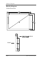
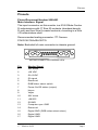
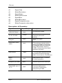
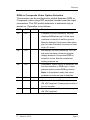
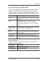
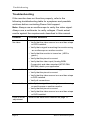
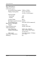
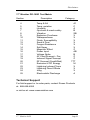
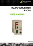
17
1700
1700
Table of Contents
Introduction and Monitor Overview .................. 3
Monitor Diagram ................................................. 4
Pinouts ................................................................ 5
Main Interface Signal ........................................................ 5
External Control Interface ................................................. 8
RGB or Composite Video Option Selection ...................... 9
Installation Instructions ................................... 10
Operation .......................................................... 12
Power Status LED ........................................................... 12
Front Switch Panel Features ........................................... 12
On Screen Display (OSD) Main Menu ............................ 13
Source Submenu ............................................................ 13
Display Submenu ............................................................ 14
Scaling/Position & Size Control Submenu ...................... 14
Picture in Picture Control Submenu ................................ 15
Troubleshooting ............................................... 16
Specifications ................................................... 18
17” Monitor DO-160D Test Matrix ................................... 19
Technical Support ............................................ 19
Disclaimer ......................................................... 20
17” Slimline LCD
Page 1
1020 Owen Loop South Eugene OR 97402
541-342-3802
www.rosenaviation.com
Doc # 9000677 Rev. C
*9000677*
Introduction and Monitor Overview
Introduction and Monitor Overview
Welcome to the 1700 Technical Manual for the 17" Slimline
LCD monitor. This manual provides an overview of monitor
details including:
•
•
•
•
•
Pinouts
Installation
Operation
Troubleshooting
Specifications
The 1700 base model includes the following features:
•
•
•
•
•
•
•
•
•
17" diagonal viewing area
NTSC/PAL/SECAM (Composite video)
Analog RGB (Computer video)
1280 x 1024 screen resolution (SXGA)
On Screen Display (OSD) functions
Status LED
Configurable Picture in Picture (PIP)
28 volt power supply
Front switch panel
The 1700 base model accommodates the following optional
controllers (sold separately):
•
•
IR remote control
External 7-button controller
17” Slimline LCD
Page 3
Monitor Diagram
Monitor Diagram
Outline Dimensions
FRONT
Page 4
Rosen Aviation Displays
Pinouts
Pinouts
Pinout Document Number 9000493
Main Interface Signal
The input connector on this monitor is a 21W4 Male Combo
D-subminiature with 17 Size 20 contacts (standard density
D-sub) and four Size 8 coaxial contacts, mounting in a Size
4 D-subminiature shell.
Recommended mating connector: ITT Cannon:
P/N DCA21WA4SA197FO.
Note: Backshell of main connector is chassis ground.
MATING CONNECTOR LOADING VIEW
Pin
Monitor Signal
1
28V return
2
+28 VDC
3
IR +5VDC
4
IR signal
5
Reserved
6
RGB/Video select switch
7
Power On/Off status (output)
8
Hsync
9
Vsync
10
28V return
11
+28VDC
12
IR GND
13
Computer sync GND
14
Reserved
15
Digital GND (RGB video select return)
16
Digital GND
17
Digital GND
17” Slimline LCD
Page 5
Pinouts
A1
Signal Red
A1
Shield Red return
A2
Signal Green
A2
Shield Green return
A3
Signal Blue
A3
Shield Blue return
A4
Signal Composite video
A4
Shield Composite video return
Description of Operation
Signal
Input/Output
Description
+28V, 28V Return
Input
Aircraft power supply
IR +5V, IR GND
Output
Power for optional IR
receiver
IR signal
Input
IR receiver signal
input
RGB/Video select
switch
Input
TTL level input. Used to select
which input (RGB or Composite)
is displayed. Method of selection
set by DIP switches. Refer to
“RGB or Composite Video Option
Selection” on page7” .
Status output
output
TTL level output indicates monitor
is powered on when logic High
(Max. current draw is 10 milliAmps)
Hsync,
Vsync
Input
RGB graphics input, TTL level
470 ohm termination
Computer sync GND
Input
Reference ground for RGB sync
Digital GND, pins 15,
16, 17
Input
Common digital ground
connection, connected to
Computer sync GND
Page 6
Rosen Aviation Displays
Pinouts
Signal
Input/Output
Description
A1 signal/shield
Input
Red graphics input, 1 Vpp,
75 ohm
A2 signal/shield
Input
Green graphics input, 1 Vpp,
75 ohm
A3 signal/shield
Input
Blue graphics input, 1 Vpp,
75 ohm
A4 signal/shield
Input
Composite video
input, 1 Vpp, 75 ohm
17” Slimline LCD
Page 7
Pinouts
External Control Interface (0300-402)
The external VIP control interface is a 9-pin standard density
D-subminiature male connector.
Pin
Control Signal
1
Power On/Off
2
Source Select
3
N/C
4
Up
5
Down
6
Menu/Select
7
Left
8
Right
9
Ground (Switch Common)
Page 8
Rosen Aviation Displays
Pinouts
RGB or Composite Video Option Selection
The monitor can be configured to switch between RGB or
Composite video using DIP switches located near the input
connectors. The DIP switch selection is detected only at
power on. Operation is as follows:
SW1
SW2
On
Off
SW3
-
Function
Constant Ground Switching. Monitor
displays RGB when pin 6 of the main
interface connector is held to ground.
Monitor displays Composite video when
pin 6 of main interface connector is held
High (5 V max.).
Off
On
-
Momentary Ground Switching. Pin 6 of
the main interface connector toggles
display between Composite/RGB on
transition to low. Monitor recalls last
setting at power up.
Off
Off
-
Autodetect. When Vsync is detected, the
monitor switches to RGB input. Vsync
present assumes that RGB is present.
Note: In Autodetect mode, the menu
selection of video source is disabled.
On
On
-
Autodetect.
-
-
Off
Monitor defaults to Off when power
(28 VDC) applied. Press power button to
turn on monitor.
-
-
On
Monitor defaults to On when power
(28 VDC) applied.
17” Slimline LCD
Page 9
Installation Instructions
Installation Instructions
The monitor can be mounted from any combination of two
sides.
FRONT
MONITOR TOP
MONITOR BOTTOM
FRONT
MONITOR SIDES
Page 10
Rosen Aviation Displays
Installation Instructions
MONITOR REAR
Warning!
Maximum screw penetration depth:
Top
.75 inches
Bottom .75 inches
Sides .75 inches
Rear
.50 inches
Natural Convection Installation
T here are three display venting configurations
recommended for a natural convection installation:
Option A = Top and Bottom, or
Option B = Top and Rear, or
Option C = Top, Bottom, and Rear
Design considerations:
• Display vents on selected surfaces should be
unobstructed.
• Airway before display vents should be clear of
obstructions for a minimum distance of 1".
• Airway before display vents should be clear of
bends for a minimum distance of 1".
• Airway inlet(s) or outlet(s) should have a
minimum open area of 4 sq in.
Note: Each mounting hole includes a 10-32 screw. To install the monitor,
remove only the screws that will be used to install the monitor. Do not
remove the 4-40 flathead screws.
Note: Application requires listed connector backshell (Positronics
D37000GVL-1023.0) due to space constraints and 21WA4 combo
connector.
17” Slimline LCD
Page 11
Operation
Operation
Power Status LED
The front switch panel includes a power status LED.
LED StatusDescription
Green
Monitor is on.
Red
Monitor is in Standby mode.
Front Switch Panel Features
To operate the 17" LCD monitor, use the front switch panel
buttons shown below. (External controllers or IR remote
control options available separately.)
Status LED
1
2
3
4
1
Menu/ Sel
Press to view the OSD Main menu and to
select the highlighted menu option.
2
Source
Press to toggle the video source between
Analog RGB and Composite video. Note: Only
functions when DIP switch is set to Momentary
Ground.
3
Press to select a menu option, or to increase
or decrease a value.
4
Power
Press to power the monitor on or off.
Page 12
Rosen Aviation Displays
Operation
On Screen Display (OSD) Main Menu
The On Screen Display (OSD) provides a set of menus that
enable you to adjust or view monitor features. Main menu
selections lead to submenus with additional choices. Press
the Menu button on the switch panel to see the Main menu.
Menu option
Description
Source
Select Analog RGB or Composite video signal
source.
Display
Image quality control. Adjust contrast,
brightness, saturation, hue in Composite
video. Adjust brightness, contrast, in Analog
RGB.
Video Scaling/
Image position and expansion control. Adjust
Position & Size
image position, and aspect ratio.
Control
Zoom
Press to zoom in and to zoom out to
original image.
Smart Setting
PIP Config.
Analog RGB only. Automatic adjustment.
Analog RGB only. PIP source, size and position
control.
Source Submenu
Choose “Source” from the Main menu to see the Source
submenu, described below.
Menu option
Description
Analog RGB
Computer applications.
Composite video
Video applications.
17” Slimline LCD
Page 13
Operation
Display Submenu
Choose “Display” from the Main menu to adjust monitor
features, described below.
Menu option
Description
Brightness
40-step brightness control.
Contrast
40-step contrast control.
Saturation
Composite video only. Adjust color tone.
Hue
Composite video only. Adjust color tint.
Scaling/Position & Size Control Submenu
Choose “Scaling” (Composite video) or “Position & Size Control”
(Analog RGB) from the Main menu to see the submenu,
described below.
Menu option
Description
Position
Analog RGB only. Press to move
the display image.
Fill Screen
Maximize the image size.
Fill to Aspect Ratio
Adjust image aspect ratio to 4:3.
Page 14
Rosen Aviation Displays
Operation
Picture in Picture Control Submenu
Choose “PIP Control” from the Main menu only when Analog
RGB video is selected to see the PIP submenu, described
below.
Menu option
Description
PIP Size
Select small, medium, or large to turn on
PIP and select a window size. Select PIP
off to turn off PIP.
PIP Horizontal Position Press to move the PIP window left or
right.
PIP Vertical Position
17” Slimline LCD
Press to move the PIP window up or
down.
Page 15
Troubleshooting
Troubleshooting
If the monitor does not function properly, refer to the
following troubleshooting table for symptoms and possible
solutions before contacting Rosen field support.
Note: Always use an oscilloscope to verity the video signal.
Always use a multimeter to verify voltages. Check actual
results against the requirements described in this manual.
Problem
Possible Solutions
No video
• Verify that the video source is on and has a tape
or DVD installed.
• Verify that a signal is reaching the monitor using
an oscilloscope or another monitor.
• Verify that the monitor is turned on. (LED is
green.)
• Verify that the pinout is correct.
• Verify that the video input (Analog RGB/
Composite) and video standard (NTSC/PAL/
SECAM) match your application.
Screen is black
• Verify that the monitor is receiving power.
• Verify that the pinout is correct.
• Verify that the video source is on and has a tape
or DVD installed.
• Verify all connections.
Screen is blue
• Verify that a signal is reaching the monitor using
an oscilloscope or another monitor.
• Verify that the pinout is correct.
• Verify that the video source is on and has a tape
or DVD installed.
Color is out of
Refer to the Main menu features on page 11.
adjustment
Page 16
Rosen Aviation Displays
Troubleshooting
Problem
Image flickers
Possible Solutions
• Verify that the signal cable is secure.
• Verify that the vertical frame frequency is 75 Hz
or less. If using the monitor with a PC in
Windows, change the Display Control Panel to
60 Hz to achieve the best performance.
Image is distorted • Verify pinouts.
• Verify that a signal is reaching the monitor using
an oscilloscope or another monitor.
• Examine the monitor for pinched or damaged
cables.
17” Slimline LCD
Page 17
Specifications
Specifications
LCD Performance
Screen Resolution (pixels) 1280 w x 1024 h
Display Viewing Area
337.9 x 270.3mm
(13.30 x 10.64 inches)
Viewing Angle
Horizontal
±80º
Vertical
±80º
Contrast Ratio
350:1
Backlight Lamp Life (hours) 50,000
Screen Brightness
200 cd/m2 (250 measured)
Mechanical Packaging
Weight
Power Requirements
Video Performance
Video Standards
Graphics Standards
Video input
Operating Temperature
Warranty
Page 18
8 lbs ± 5%
28VDC 40W max.
NTSC, PAL, SECAM
VGA, SVGA, XGA, SXGA
(75 Hz max)
1V peak-to-peak, 75 Ohms
0ºC - 50ºC
2yr
Rosen Aviation Displays
Disclaimer
17” Monitor DO-160D Test Matrix
Section
4
5
6
7
8
9
10
11
12
13
14
15
16
17
18
19
20
21
22
23
24
25
Description
Temp & Alt
Temp variation
Humidity
Op shock & crash safety
Vibration
Explosion Proofness
Waterproofness
Fluids Susceptibility
Sand & Dust
Fungus Resistance
Salt Spray
Magnetic Effect
Power Input
Voltage Spike
AF Cond Suscept – Pwr
Induced Signal Suscept
RF Suscept (Cond&Rad)
Emission of RF Energy
Lightning Induced Trans
Lightning Direct Effects
Icing
Electrostatic Discharge
Category
A1
C
A
B
SB
X
X
X
X
X
X
Z
AB
B
Z
Z
TTT
M
X
X
X
A
Technical Support
For field support or to order parts, contact Rosen Products
at: 888-668-4955
or visit us at: www.rosenaviation.com
17” Slimline LCD
Page 19
Disclaimer
All information, including illustrations, is believed to be reliable. Users and/
or installers, however, should independently evaluate the suitability of
each product for their application. Rosen makes no warranties as to the
accuracy of completeness of the information, and disclaims any liability
regarding its use or installation. Rosen’s only obligations are those in the
Rosen Standard Terms and Conditions of Sales for this product, and in no
case will Rosen be liable for any incidental, indirect or consequential
damages arising from the sale, resale, use or misuse of the product.
Specifications are subject to change without notice. Rosen reserves the
right to make changes - without notification to buyer - to materials or
processing that do not affect compliance with any applicable
specifications.
Page 20
Rosen Aviation Displays