1
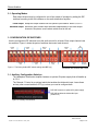
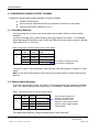
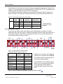
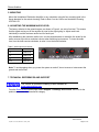
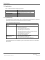
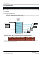
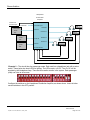
ELECTRONI C REVI SI ON CONTROLLED Document Number 100318 Rev A Rosen Aviation Technical Manual, Headphone Distribution Amplifier 0700-001 © 2008 by Rosen Aviation, LLC All Rights Reserved The information contained herein is proprietary to Rosen Aviation, LLC. No part of this publication may be reproduced, transmitted, transcribed, stored in a retrieval system, or translated into any language in any form by any means without the written authorization from Rosen Aviation, LLC, except as allowed under copyright laws. Disclaimer of Liability The information contained in this document is subject to change without notice. Because we are continuously improving and adding features to our products, Rosen Aviation, LLC reserves the right to change specifications without prior notice. Rosen Aviation, LLC shall not be liable for technical or editorial errors or omissions contained herein. Rosen Aviation, LLC 1020 Owen Loop South Eugene, OR 97402 541.342.3802 888.668.4955 Fax: 541.342.4912 www.rosenaviation.com Document Number: 100318 Template: 4.2.3-6-FM; Revision A; 16 May, 2005 Revision: Date: 03/11/08 A Page 2 of 13 Rosen Aviation Contents 1. INTRODUCTION ................................................................................................................ 4 1.1. Unpacking .................................................................................................................... 4 2. DEFINITIONS ..................................................................................................................... 4 2.1. Operating Modes.......................................................................................................... 5 3. CONFIGURATION DIP SWITCHES................................................................................... 5 3.1. Auxiliary Configuration Switches .................................................................................. 5 4. CONFIGURING A SINGLE OUTPUT CHANNEL .............................................................. 6 4.1. Fixed Mode Example ................................................................................................... 6 4.2. Switched Mode Examples ............................................................................................ 6 4.3. Installation Example ..................................................................................................... 7 5. MOUNTING ........................................................................................................................ 8 6. ADJUSTING THE MAXIMUM AUDIO LEVEL ................................................................... 8 7. TECHNICAL REFERENCES AND SUPPORT................................................................... 8 7.1. DO-160E Qualifications ................................................................................................ 8 7.2. Specifications ............................................................................................................. 10 7.3. Troubleshooting ......................................................................................................... 10 8. REVISION HISTORY........................................................................................................ 11 9. APPENDIX ....................................................................................................................... 11 9.1. Configuration Diagrams ............................................................................................. 11 Document Number: 100318 Template: 4.2.3-6-FM; Revision A; 16 May, 2005 Revision: Date: 03/11/08 A Page 3 of 13 Rosen Aviation 1. INTRODUCTION The Headphone Distribution Amplifier 0700-001 features three audio inputs, a pilot mic input, and eight controllable audio outputs. The pilot mic input will override the other inputs when active. The unit is designed to integrate into any entertainment system with analog audio capability and controllers that allow you to select different audio sources in the aircraft. This guide describes general configuration information for the Rosen Headphone Distribution Amplifier with any audio source equipment to supplement the Outline and Installation Drawing (P/N 0700-001-CD). Note: Only trained and qualified personnel should perform installation and service. 1.1. Unpacking The following parts are shipped with the Headphone Distribution Amplifier Outline and Installation Drawing (P/N 0700-001-CD) Headphone Distribution Amplifier (P/N 100312) Headphone Distribution Amplifier CD (P/N 101156) The Outline & Installation drawings are also available at www.rosenaviation.com. From the Rosen Aviation home page, select Support Drawings and Pinouts, and look for the product name under the Accessories category. 2. DEFINITIONS Independent All eight outputs, or channels, operate independently. channels Source select A switch that enables you to select between three different audio input sources independently. Output channel An audio output from the Headphone Distribution Amplifier (outputs 1-8). Input channel Refers to the line-level audio source (inputs channels A, B, and C. For example, a DVD player, iPod, and RosenView VX. Document Number: 100318 Template: 4.2.3-6-FM; Revision A; 16 May, 2005 Revision: Date: 03/11/08 A Page 4 of 13 Rosen Aviation 2.1. Operating Modes Each output channel may be configured to one of two modes of operation by setting the DIP switches according to the ON indicators on the audio distribution amplifier. Fixed output Keeps the output channel set to a specific input channel: either A, B, or C. Switched output Allows the user to select input channels independently of the other output channels. Requires a source select switch wired to the unit. 3. CONFIGURATION DIP SWITCHES Use the configuration DIP switches to set the audio control for all seats. Each output channel uses two switches. Figure 1 shows the pairs of switches that control each channel. Output Ch 1 Output Ch3 Output Ch2 Output Ch4 5V Power Output Ch7 Output Ch5 Output Ch6 Figure 1 The factory default DIP switch settings are OFF (up) Output Ch8 Ch C Control Small bank DIP switches SW1-SW6 3.1. Auxiliary Configuration Switches The Headphone Distribution Amplifier features an optional 5V power supply that will handle up to 0.5 A. The Channel C Control is an optional switch that enables the third audio input. Leave these and any other unused switches OFF (up) unless you need to configure them. DIP SW5 controls an optional 5V power supply DIP SW6 enables the third audio input (Channel C) Figure 2 Auxiliary DIP switches Document Number: 100318 Template: 4.2.3-6-FM; Revision A; 16 May, 2005 Revision: Date: 03/11/08 A Page 5 of 13 Rosen Aviation 4. CONFIGURING A SINGLE OUTPUT CHANNEL Configuring a single output channel depends on several variables. Number of audio inputs Use of a source select switch (such as a controller, IR remote, or at the seat) Choice of fixed inputs: channel A, B, or C 4.1. Fixed Mode Example If you are using only one input, you do not need a source select switch or need to enable channel C. If you do not need a source select switch for the output channel, see Table 1. This example shows that using DIP switches 1 and 2 (SW1 and SW2) will set the output to receive a desired input: either A, B, or C for seat 1. Table 1 Fixed mode: one audio source and no select switch DIP DIP SW1 SW2 Input Channel OFF OFF A 1 OFF ON B ON OFF C* ON ON N/A The audio is constantly on pilot mic with this configuration *Channel C control, SW6 (small bank), does not have to be ON to listen to Channel C in fixed mode. Note: Do not set all DIP switches to ON. Doing so will cause the PA to override the audio all the time. 4.2. Switched Mode Examples If you use a source select switch, see Table 2. This example shows that channels A and B for seat 1 are enabled using a source select switch. The Channel C enable switch (SW6) is OFF. Table 2 Two audio sources (A & B) and a select switch DIP DIP Input SW1 SW2 Channel A&B OFF OFF 1 N/A OFF ON ON OFF N/A ON ON N/A The DIP switch settings are identical to the fixed mode Channel A in Table 1; the difference is that a source select switch is used to toggle between inputs A and B. For independent switching, configure desired seats to input Channel A. Document Number: 100318 Template: 4.2.3-6-FM; Revision A; 16 May, 2005 Revision: Date: 03/11/08 A Page 6 of 13 Rosen Aviation To configure the remaining output channels (2-8), copy the appropriate switch settings from Tables 1-3. Fixed modes will use either an ON/OFF, OFF/ON, or OFF/OFF combination and switched modes will always use the OFF/OFF combination. If you use three audio sources and a source select switch, configure the DIP switches as shown in Table 3. The Channel C Enable switch must be ON to use the third audio input. Table 3 Three audio sources and a select switch DIP DIP DIP SW6 SW1 SW2 Channel C Channel ON OFF OFF 1 ON OFF ON ON ON Output Channel A, B, & C N/A OFF ON N/A ON ON N/A The N/A outputs do not switch the audio properly 4.3. Installation Example You can mix the audio control and configure each seat differently, as shown in Figure 3. Channels 5 and 6 are set to Input A, and these seats have a choice. Either they may have a source select switch to allow them to change their channel, or they can remain without a source select switch and stay on input A. Output Ch 1 Output Ch3 Output Ch4 Output Ch2 5V Power OFF Output Ch7 Output Ch5 Output Ch6 Output Ch8 Ch C ENABLED Figure 3 Configuration DIP switch settings Table 4 DIP switch settings for Figure 3 Output Channel # Input Setting Fixed Mode Input Setting Switched Mode Channel 1 C N/A Channel 2 C N/A Channel 3 B N/A Channel 4 B N/A Channel 5 A A, B, C Channel 6 A N/A Channel 7 C N/A Channel 8 B N/A Channels 1, 2, and 7 are set to Input C. Channels 3, 4, and 8 are set to Input B. The seats for these six channels do not have source select switches. Only channels 5 and 6, which are set to Input A, can use a source select switch. This is because the DIP switches controlling these channels are turned OFF. Tip: For more configuration examples, see the Appendix on page 11. Document Number: 100318 Template: 4.2.3-6-FM; Revision A; 16 May, 2005 Revision: Date: 03/11/08 A Page 7 of 13 Rosen Aviation 5. MOUNTING Mount the Headphone Distribution Amplifier in any orientation using the four mounting slots in the flange brackets on the exterior housing. Refer to Note 3 on the Outline and Installation Drawing 0700-001-CD. 6. ADJUSTING THE MAXIMUM AUDIO LEVEL The factory defaults for the potentiometers, as shown in Figure 4, are set to line level. This means that the signal coming out of the amplifier is equal to the signal going in. Adjust each knob individually to set the maximum audio level for each input. After establishing the maximum audio level, use the potentiometers to match the line levels for the audio sources to provide a consistent volume when switching input sources. To lower the audio level, turn the knob counter-clockwise; to raise it, turn the knob clockwise. Table 5 Audio input level controls Potentiometer Control A Channel A B Channel B C Channel C PA Pilot mic Figure 4 Line-level positions for potentiometers Note: To avoid popping when you power the system on and off, do not reverse or interconnect the ground and return lines. 7. TECHNICAL REFERENCES AND SUPPORT The Outline & Installation drawing is also available at www.rosenaviation.com. From the Rosen Aviation home page, select Support Drawings and Pinouts, and look for the product name under the Accessories category. Document Number: 100318 Template: 4.2.3-6-FM; Revision A; 16 May, 2005 Revision: Date: 03/11/08 A Page 8 of 13 Rosen Aviation 7.1. DO-160E Qualifications Table 6 DO 160E test criteria to which we test the Headphone Distribution Amplifier Description DO-160E Section DO-160E Category Temperature and Altitude 4.0 A1 Temperature Variation 5.0 C Humidity 6.0 A Operational Shocks & Crash Safety 7.0 B Vibration 8.0 S, Curve B Explosive Atmosphere 9.0 N/A Waterproofness 10.0 N/A Fluids Susceptibility 11.0 N/A Sand and Dust 12.0 N/A Fungus Resistance 13.0 N/A Salt Spray 14.0 N/A Magnetic Effect 15.0 A Power Input 16.0 Z,B Voltage Spike 17.0 A Audio Frequency Conducted Susceptibility – Power Inputs 18.0 Z Induced Signal Susceptibility 19.0 AC Radio Frequency Susceptibility (Radiated and Conducted) 20.0 T Emission of Radio Frequency Energy 21.0 B Lightning Induced Transient Susceptibility 22.0 N/A Lightning Direct Effects 23.0 N/A Icing 24.0 N/A Electrostatic Discharge (ESD) 25.0 A Fire, Flammability 26.0 N/A Document Number: 100318 Template: 4.2.3-6-FM; Revision A; 16 May, 2005 Revision: Date: 03/11/08 A Page 9 of 13 Rosen Aviation 7.2. Specifications Table 7 Headphone Distribution Amplifier specifications Weight .85 lbs [.3856 kg] Dimensions 7.7” (W) x 1.4” (H) x 5” (D) [19.56 cm (W) x 3.56 cm (H) x 12.7 cm (D)] Power Requirements 28V DC Operating Temperature 0ºC - 50ºC Warranty 2 year 7.3. Troubleshooting If the audio does not function properly, refer to the following troubleshooting tips for symptoms and possible solutions before contacting Rosen Aviation field support. Table 8 Troubleshooting tips and solutions Problem Possible Solutions Power LED does not illuminate (GREEN) Verify pinout to power input connection is correct. No sound Wait at least five seconds after turning on the Headphone Distribution Amplifier power. Verify the pinout for audio is correct. Verify audio signal on connector pins. Adjust the potentiometers clockwise to increase audio level. Verify that audio source is in play mode. Check for damaged connector pins. Check DIP switch configuration. Amplifier does not cycle through sources Check the DIP switch settings and adjust. Check for damaged connector pins. Verify source select switch operation and pinout. If you need assistance with an installation, please contact Rosen Aviation at 541.342.3802 or 888.668.4955. Document Number: 100318 Template: 4.2.3-6-FM; Revision A; 16 May, 2005 Revision: Date: 03/11/08 A Page 10 of 13 Rosen Aviation 8. REVISION HISTORY Revision Date A 03/11/08 Revision Description EC # New release 08079 9. APPENDIX 9.1. Configuration Diagrams The following diagrams illustrate different ways to configure the unit’s connections to integrate audio control into an in-flight entertainment system. Headphone Distribution Amplifier PA Override Discrete Input PA Override In Pilot Audio DVD Player Pilot Mic Input Channel 1 Seat 1 Channel A Audio Out Channel 2 N/C Channel B N/C Channel C Seat 2 Channel 3 Channel 4 Seat 3 Seat 4 Example 1 – The aircraft has four passenger seats. Each seat has a headphone jack without source select switch. There is only one audio source in the system (DVD player). Configure the switches on the Headphone Distribution Amplifier, as shown above. Leave all other unused switches in the OFF position. Document Number: 100318 Template: 4.2.3-6-FM; Revision A; 16 May, 2005 Revision: Date: 03/11/08 A Page 11 of 13 Rosen Aviation Headphone Distribution Amplifier PA Override Discrete Input PA Override In Pilot Audio DVD Player Pilot Mic Input Channel 1 Seat 1 Select Switch Channel A Audio Out Channel 2 Seat 2 Select Switch DVD Player Audio Out DVD Player Audio Out Channel B Channel 3 Channel 4 Channel C Seat 3 Select Switch Seat 4 Select Switch SS1 SS2 SS3 SS4 Example 2 – The aircraft has four passenger seats. Each seat has a headphone jack with a select switch. These jacks also have LEDs for lighting. The LEDs require +5v DC. The +5v DC will be supplied by the Headphone Amp. There are three audio sources in the system. Each passenger (seat) can listen to all sources. Configure the switches on the Headphone Distribution Amplifier, as shown above. Leave all other unused switches in the OFF position. Document Number: 100318 Template: 4.2.3-6-FM; Revision A; 16 May, 2005 Revision: Date: 03/11/08 A Page 12 of 13 Rosen Aviation Headphone Distribution Am plifier PA Override PA Override In Discrete Input Pilot Audio DVD Player Pilot Mic Input Channel 1 Seat 1 Channel A Audio Seat 2 Channel 2 O ut XM Radio Audio O ut N/C Channel B N/C Channel C Channel 3 Channel 4 Seat 3 Seat 4 Seat 5 Channel 5 Select Switch Seat 6 Channel 6 Select Switch Channel 7 Channel 8 SS5SS5 SS6SS6 SS7 SS7 SS8 SS8 Seat 7 Select Switch Seat 8 Select Switch Example 3 – The aircraft has eight passenger seats. Seats 1-4 have headphone jacks with no select switch. These seats have access to XM Radio audio only, which is assigned to Channel B. Seats 5-8 have headphone jacks with select switches. These jacks also have LEDs for lighting. The LEDs require +5v DC, which will be supplied by the Headphone Amplifier (SW5 on the small bank of switches). Seats 5-8 can listen to either audio source: XM Radio or DVD Player. Configure the switches on the Headphone Distribution Amplifier, as shown above. Leave all other unused switches in the OFF position. Document Number: 100318 Template: 4.2.3-6-FM; Revision A; 16 May, 2005 Revision: Date: 03/11/08 A Page 13 of 13