1
Owner's
Manual/Manual
IDei Propietario
1/2 HP
315MHz GARAGE DOOR OPENER
ABRIDOR DE PUERTA DE COCHERA
For Residential
Model/Modelo
Use Only/S61o
315MN_
para uso residenciai
139.53920D
m
Z
r==
!
m
¢,/}
ZI
r==
Read and follow all safety
and operating instructions
first use of this product.
rules
before
Leer y seguir todas las reglas
seguridad y las instrucciones
operaci6n antes de usar este
producto por primera vez.
Fasten the manual near the garage
door after installation.
Guardar
Periodic checks of the opener are
required to ensure safe operation.
Se deben
Sears, Roebuck and Co., Hoffman
www sears com!craflsman
Estates,
puerta
este manual
de
de
cerca de la
de la cochera.
realizar
revisiones
peribdicas del abridor de puertas
para asegurar
su operacibn
segura.
IL 60179
U.S.A
TABLE
OF CONTENTS
Introduction
2.7
Adjustment
27.29
Adjust the travel limits ...................................................................
27
Safety symbol and signal word review .....................................
2
Preparing
Adjust the force ........................................................................................
28
door ..............................................................
3
your garage
Tools needed ...................................................................................................
3
Test the safety reversal system ........................................................
29
Test The Protector System _ ..........................................................
29
..........................................................................................................
4-5
Planning
Carton inventory .........................................................................................
6
Operation
inventory
7
......................................................................................
Hardware
Assembly
Assemble
8-11
30.34
Operation safety instructions ..............................................
30
Using your garage door opener ....................................................
30
the rail and install the troIley .................................
8
Using the wall-mounted Door Control ................................
3I
Fasten the rail to the motor unit .....................................................
9
To open the door manually ....................................
31
Care of your garage door opener ............................................
32
Install the idler pulley ................................................................................
9
Install the chain/cable
10
.....................................................................................
Having a problem? .........................................................................................
33
Diagnostic chart .........................................................................................
34
]3ghten the chain ...............................................................................
11
Installation
11.26
Programming
35.36
Installation safety instructions ...................................................
11
Determine the header bracket location ............................
12
To add or reprogram a hand-held remote control ..........
35
To erase all codes ...........................................................................................
35
Install the header
3-Function Remotes ...................................................................................
35
bracket
13
.............................................................
Attach the rail to the header bracket ...........................................
14
To add, reprogram or change
Position
a Keyless Entry PIN ..................................................................................
36
...................................................................................
15
the opener
Hang the opener
..............................................................................................
16
Repair
Install the door control
17
........................................................................
Parts
37-38
Rail assembly parts ....................................................................................
37
Install the light ......................................................................................................
18
installation parts .......................................................................................
37
.....................................................................................
19
Accessories
Insta!l The Protector
System _
.........................................
release
Electrical
requirements
rope and handle ...........
18
Motor unit assembly parts ...............................................................
38
Attach the emergency
39
20-22
Fasten the door bracket .........................................................
23-24
Warranty
Connect
Repair
the door arm to the trolley ........................................
25-26
39
Parts
_ Service
Backcover
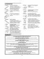
INTRODUCTION
Safety
Symbol
and Signal
Word
Review
This garage door opener has been designed and tested to offer safe service provided it is installed, operated,
maintained and tested in strict accordance with the instructions and warnings contained in this manual
Mechanical
When you see these Safety Symbols and Signal
Words on the following pages, they will alert you to
the possibility of serious injury or death if you do
not comply with the warnings that accompany them
The hazard may come from something mechanical
or from electric shock. Read the warnings carefully
Electrical
When you see this Signal Word on the following
pages, it will alert you to the possibility of damage to
your garage door and/or the garage door opener if
you do not comply with the cautionary statements
that accompany iL Read them carefully
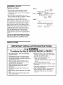
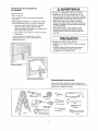
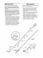
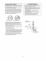
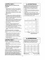
Preparing
your
garage
door
Before you begin:
• Disable locks
• Remove any ropes connected to garage door
. Complete the following test to make sure your
garage door is balanced and is nat sticking or
binding:
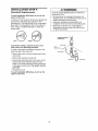
1 Lift the door about halfway as shown Release
the door If balanced, it should stay in place,
supported entirely by its springs
2 Raise and lower the door to see if there is any
binding or sticking
To preventpossible SERIOUSINJURYor DEATH:
. ALWAYScall a trained door systems technicianif
garagedoor binds, sticks, or is out of balance An
unbalancedgaragedoor may not reversewhen
required
• NEVERtry to loosen move or adjust garagedoor door
springs, cables,pulleys brackets or their hardware all
of which are under EXTREMEtension
• DisableALL locksand removeALL ropes connectedto
garagedoor BEFOREinstalling and operatinggarage
door openerto avoid entanglement
If your door binds, sticks, or is out of balance, calf a
trained door systems technician
To preventdamageto garage door and opener:
• ALWAYSdisablelocks BEFOREinstalling and operating
the opener
• ONLYoperategaragedoor openerat 120V,60 Hz to
avoid malfunction and damage
Sectional
Door
One-Piece
Door
Tools
needed
During assembly, installationand adjustment of the
opener, instructions will call for hand tools as
iE]ustrated below
PenciI
Hack
Sew
Wire Cullers
Screwdriver
Slepladder
Adjustable End Wrench
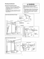
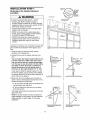
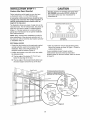
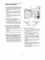
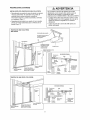
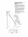
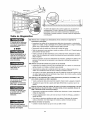
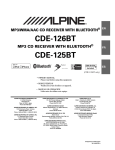
Planning
Identify the type and height of your garage door
Survey your garage area to see if any of the
conditions below apply to your installation, Additional
materials may be required,, You may find it helpful to
refer back to this page and the accompanying
illustrations as you proceed with the installation of
your opener
Do you have an access door in addition to the
garage door? If not, Model 53702 Emergency Key
Release is required See Accessories page.
Look at the garage door where it meets the floor,
Any gap between the floor and the botlom of the
door must net exceed 1/4" (6 mm) Otherwise, the
safety reversal system may not work properly, See
Adjustment Step 3 Floor or door should be
repaired_
Depending on your requirements, there are several
installation steps which may calf for materials or
hardware not included in the carton,
• Installation Step I - Look at the wall or ceiling
above the garage door, The header bracket must
be securely fastened to structural supports.
- Installation Step 5 - Do you have a finished ceiling
in your garage? If so, a support bracket and
additional fastening hardware may be required.,
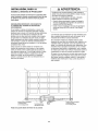
SECTIONAL DOOR INSTALLATIONS
• Do you have a steel, aluminum, fiberglass or glass
panel door? tf so, horizontal and vertical
reinforcement is required (Installation Step 11).
o The opener should be installed above the center of
the door If there is a torsion spring or center
bearing plate in the way of the header bracket, it
may be installed within 4 feet (1,22 m) to the left or
fight of the door center See Installation Steps 1
and 11,
- Installation Step 10 - Depending upon garage
construction, extension brackets or wood blocks
may be needed to install sensors.
. Installation Step 10-Alternate floor mounting of
the safety reversing sensor wilt require hardware
not provided.
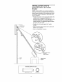
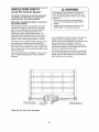
SECTIONAL
• If your door is more than 7 feet (2,13 m) high, see
rai] extension kits listed on Accessories page
DOOR INSTALLATION
FINISHED
Horizontal
and vedical
CEILING
Suppoll brackel &
fastening hardware
is required,
See page 16
reinforcement
is needed !of lightweight
garage doors
(_iberglass,
steel, aluminum,
door with
glass panets, elc ) See page 23 for details
Slack in chain tension
is nolTaal when
garage door is closed
OR
Rail
Motor unit
Spdng
Wall mounte_
Door
Header
Cenirol
CLOSED
POSIT_ON
Brackel
_
Trolley
Slop Boll
Centertine
Trolley
o!
I
Cha{n
Gap between
t=oor
and bottom of door
must not exceed 1/4",
Emergency
Release
Rope & Handle
Safety
Reversing
SetlBOt"
Arm
Dam
Bracket
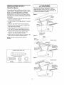
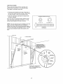
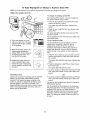
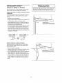
Planning
(Continued)
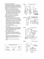
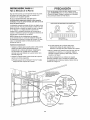
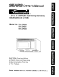
ONE-PIECE DOOR INSTALLATIONS
Without a propedyworking safety reversalsystem,
persons (particularlysmall children) could be
SERIOUSLY
iNJUREDor KILLEDby a closing garage
door
• Thegap betweenthe bottom of the garagedoor and
the floor MUSTNOTexceed1/4" (6 ram) OtherMse,
the safety reversalsystem may not work properly
• Thefloor or the garage door MUST be repairedto
eliminatethe gap
o Generally, a one-piece door does not require
reinforcement, If your door is lightweight, refer to
the information relating to sectional doors in
Installation Step 11,
o Depending on your door's construction, you may
need additional mounting hardware for the door
bracket (Step 11)_
ONE-PIECE
DOOR WITHOUT
TRACK
FINISHED
CEILING
Support bracket
& fastening
hardwaze is required
See page 16
Rail
_
Header Wall
Slack in chain tension
is aorta!! when
garage door is closed
\
Meier Unit
Access
Door
O
Safety
Gap between floor
Safety Reversing Sensor
ONE-PIECE
and bottom
Reveming
Sensor
of door must
not exceed
I14 _ {6 ram)
DOOR WITH TRACK
[
CLOSED
r.-'/._ Trottey
Stop
Access
Door
Of
Door
Gap between floor
and bottom
_afety
Reversing Sensor
Reversing
Seesor
Of deer
must not exceed I/4" (6 ram)
Boll
POSITION
Cable
Chain
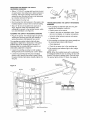
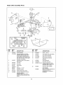
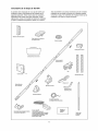
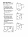
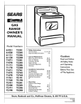
Carton
inventory
Your garage door opener is packaged in one carton
which contains the motor unit and all pads illustrated
below Accessories witf depend on the model
purchased If anything is missing, carefully check the
packing material, Parts may be stuck in the foam
Hardware for assembly and installation is shown on
the next page., Save the cation and packing material
until instaElationand adjustment is compIete,
Trol_ey
Door
y
Control B[Jtten
SIngle_Function
with
Visor
Remote
Control
Clip
Chain
Spreader
Rall
idler
CentedBack
Sections
Pulley
I1
Chain and Cable
Meier
Unit with
Light
Lena
Hanging
Brackets
Rail
Front (t;aader)
Section
Door 8racket
Header Bracket
2-Conductor BeI_ Wire
White & Whitened
Curved
Door
Arm Section
Safety Sensor
Bracket (2)
_qe Prolector
System
°
(2) Safety Reversing
Sensors
(1 Sending
Eye and 1 Receiving
wflh 2-Conductor
White &
Whlle/B_ack
Bell W_re altaehed
l
and
Literature
Safety Labels
Eye)
Stra{ght Door
Arm Section
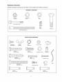
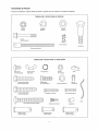
Hardware
Bnventory
Separate all hardware and group as shown below for the assembly and installation procedures
ASSEMBLY
©
Lock
©
Nut
1/4"-20
HARDWARE
(2)
Belt 1/4_-20xl-314"
Lock Washer
Nut
3/8'
3/8"(I}
(l)
(2)
Master
Unk (2)
T_'otley Threaded
Shaft
(1)
INSTALLATION
Cardege
Bolt
1t4"-20xl/2"
Wing
(2)
Nut
t/4"-20
HARDWARE
Ring
(2)
I(iler Bolt (I)
Nut
Faslener
5/16"-18
Handle
(8)
(3)
©
Lag Screw
5It 6*-9x t-5/8"
Hex
(2)
Bolt
Insolaled
5116"-18x7/8"
(4)
LockWasher
5/16"
(7)
Staples,
(30)
_]ilililiIililitililil
Screw
5116"-18x!-718"
(2)
6ABxtq/4"
(2)
Screw
6-32x1"
(2)
Rope
Carriage Boll
5116"-18x2-l/2"
(2)
Drywall
Anchors
(2)
Spacer
(2)
°1
Clevis
5/16"xl
Pin
-lY2'
Clevis
(1)
Pin
see'x1" (_)
Clevis
Pin
5116"XI_IN"
(l)
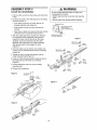
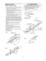
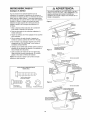
ASSEMBLY
Assemble
STEP
the
To avoid installation
garage door opener
Rail
t
& Instaff
the
Troffey
T0 prevent INJURYfrom pinching, keephandsand
fingers awayfrom the joints while assemblingthe rail
difficulties, do not run the
until instructed to do so.
The front rail has a cut out "window"at the door end
(see illustration), The hole above this window is
larger on the top of the rail than on the bottom A
smaller hole 3-1/2" (8,,9 cm) away is close to the raft
edge Rotate the back raft so it has a similar hole
close to the opposite edge, about 4-3/4" (12 cm)
from the far end,
3, Place the motor unit on packing material to protect
the cover, and rest the back end of the rail on top
For convenience, put a support under the front
end of the rail
1 Remove the straight door arm and hanging
bracket packaged inside the front rail and set
aside for Installation Step 5 and 12 NOTE: To
prevent INJURY while unpacking the rail carefully
remove the straight door arm stored within the rail
section,
5. Check to be sure there are 4 plastic wear pads
inside the inner trolley if they became loose
during shipping, check all packing material, Snap
them back into position as shown
4. As a temporary trolley stop, insert a screwdriver
intothe hole 10" (25 cm) away from the front of
the rail, as shown,,
6, Slide the trolley assembly along the rail from the
back end to the screwdriver,
2. Align the rail sections on a flat surface as shown
and slide the tapered ends into the Iarger ones=
Tabs along the side wilt lock into place
T_olIey
KEEP LARGER
HOLE ON TOP
FRONT RAIL
(TOP)
Back Rails
(TO MOTOR UNIT)
End
/
End
W_ndow
CubOul
Idler
Pufley-,_,Ylj
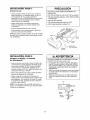
ASSEMBLY
Fasten
STEP
the
Rail
to
:
2
the
Motor
Unit
• Insert a 1/4"-20xl-3/4 bolt into the cover protection
bolt hole on the back end of the rail as shown,,
Tighten securety with a 1/4"-20 lock nuL Do NOT
overtighten,
CAUTION
]
"Toavoid
SEniOus
aamaOe
tog raOe
dooiOP n r,
use ONLYthose boitstfastenersmounted in the top of
the opener.
]
° Remove the two bolts from the top of the motor
unit.
° Place the "U" bracket, flat side down onto the
motor unit and align the bracket hole with the bolt
holes. Fasten with the previously removed bolts
• Align the rail assembly with the top of ihe motor
unit.. Slide the rail end onto the "U" bracket, all the
way to the stops that protrude on the top and sides
of the bracket,
Motor
Unit
"U" Bracket
BOll
Cover
• Atlach spreader to the motor unit with two screws
HARDWARE SHOWN ACTUAL BtZE
©
SLIDE
ASSEMBLY
Nnstall
lhe
STEP
Idler
AND
STOPS
""
SIDES
OF BRACKET
Lock
Lock Net
Bolt 1/4"_20xl-314"
RAIL TO
ON TOP
Nut
!/4"-20
Chain
Cable
3
and
Pulley
. Lay the chain/cable beside the rail, as shown,
Grasp the end of the cable and pass
approximately 12" (30 cm) of cable through the
window. Allow it to hang until Assembly Step 5,
- Remove the tape from the idler pulley The inside
center should be pro-greased If dry, regrease to
ensure proper operation.
- Place the idler pulley into the window as shown,,
° Insert the idler bolt from the top through the rail
and pulley, Tighten with a 3/8" lock washer and nut
underneath the rail until the lock washer is
compressed,
• Rotate the pulley to be sure it spins freely
• Insert a 1/4"-20xl-3/4 bolt into the trolley stop hole
in the front of the rail as shown Tighten securely
with a t/4"-20 lock nut.
HARDWARE SHOWN ACTUAL SIZE
Idler Belt
Bolt l/4"-20×t.3t4"
©
Lock Nut 1/4%20
Nut 3!8"
Lock Washer 3/8"
ASSEMBLY
Hnstall
the
STEP
4
Chain/Cable
To avoid possible SERIOUSiNJURYto fingers from
moving garagedoor opener:
o ALWAYSkeep hand dear of sprocket while operating
opener.
• Securelyattach chainspreaderBEFOREoperating,
1 Pull the cable around the idler pulley and toward the
trolley.
2 Connect the cable to the retaining slot on the trolley,
as shown (Figure 1):
• From below, push pins of master link bar up
through cable link and trolley slot
• Push master link cap over pins and past pin
notches.
Dispensing
Carton
Leave Chain and Cabte
Inside Dispensing
Carton to Prevent Kinking
o Slide clip-on spring over cap and onto pin notches
unfit both pins are securely tacked in place.
Keep Chain and Cable
Taut When Dispensing
3. With the troIley against the screwdriver, dispense
the remainder of the cable/chain along the rail
toward the motor unit into the slot on the chain
spreader, around the sprocket onto the chain
spreader and continuing to the trotley assembly.
The sprocket teeth must engage the chain
(Figure 2).
4. Check to make sure the chain is not twisted, then
connect it to the threaded shaft with the remaining
master link.
Figure 1
Master Link _._
Clip-On Sp r_n-g"
_--'_
Master
Un_ Ca
Master Unk
c,p_oosp, Mos,°,
[_,_/'Unk
Cap
//_._,_
5. Thread the inner nut and lock washer onto the
trolley threaded shaft (Figure 3)
6. Insert the trolley threaded shaft through the hole in
the trolley Be sure the chain is not twisted
(Figure 4)
7. Loosely thread the outer nut onto the trolley
threaded shaft..
8 Remove
^
..
__4;_J
/
/
Idler
/
_
_.__ur,.d
/,,_,Ii( _
_.._.)/][,'"_,
:
Pulley__..,,.,,_-i,.,,._
the screwdriver,
_L_
__
"
Shaft
U
"_'_"
C&ble
Figure
Th,.readed ', ;
L, ae_e_,,_
\
_
\Slotted
! i
Hale
i'' '_'
'
Master
_.,_
Hole
Link S_t
2
Figure
3
Bait
_,r
. _ ,"
•"
10
Shaft
Inner
Lock
Washer
5l_ 6"
5116"
Nut
I
_
""
;
Pin
.,.,.Nalch
U_ Bar
ASSEMBLY
Tighten
STEP
the
5
Chain
Figure 1
Tro!ley
Outer Lack
Nut
Washer
• Spin the inner nut and lock washer down the
trolley threaded shaft, away from the trolley..
To _ghlen Outer Nut _
- To tighten the chain, turn outer nut in the direction
shown (Figure 1).
,, When the chain is approximately 1/4" (6 mm)
above the base of the rail at its midpoint, reqighten
the inner nut to secure the adjustment.
,
U
_
Threaded
Shatl
/
TO Tlghlen
Figure 2
Sprocket noise can result if chain is too loose
When installation is complete, you may notice some
chain droop with the door dosed This is normal. If
the chain returns to the position shown in Figure 2
when the door is open, do not re-adjust the chain
Chain
NOTE: During future maintenance, ALWAYS puff the
emergency release handle to disconnect trolley
before adjusting chain. You may notice loosening of
chain after Adjustment Step 3 (Test the Safety
Reversal System) Check for proper tension and
readjust chain ff necessar]z Then repeat Adjustment
i
Base el Ra
Mid length ut Roll
Step 3.
You have now finished assembling your garage
door opener. Please read the following warnings
before proceeding to the installation section.
_._b1,_, ,,,u_,
L
,
i
i L J L_ i
, Jl
ULLL_ LL
±H LuJl
INSTALLATION
IMPORTANT INSTALLATION
INSTRUCTIONS
To reduce the risk of SEVERE INJURY or DEATH:
1 READANDFOLLOWALL INSTALLATION
WARNINGS
AND INSTRUCTIONS.
2 Install garagedoor opener only on properly balanced
and lubricated garagedoor An improperly balanced
door may net reversewhen required and could result in
SEVEREINJURYor DEATH
3 All repairsto cables,spring assembliesand other
hardwareMUSTbe madeby a traineddoor systems
technicianBEFOREinstalling opener,
4 Disableatt locks and remeveall ropesconnectedto
garagedoor BEFOREinstalling openerto avoid
entanglement..
5 Install garagedoor opener 7 feet (2 13 m) or more
abovefloor
6 Mount emergencyreleasehandle6 feet (183 m) above
floor
7 NEVERconnectgaragedoor openerto power source
until instructedto do so
8..NEVERwearwatches,rings or loose clothing while
instalgng or servicingopener They could be caught in
garagedoor or openermechanisms,
9 Install walt-mountedgaragedoor control:
• within sight of the garagedoor.
, out of reachof children at minimum height of 5 feet
(15 m).
• awayfrom all moving parts of the door
I0 Placeentrapmentwarninglabel on wal! next to garage
door control
11 Placemanua]release/safetyreversetest label in plain
view on insideof garagedoor
12 Uponcompletion of installation,test safety reversal
system Door MUSTreverseon contactwith a
I-1t2" (38 cm) high object (or a 2x4 laid flat) on
the floor
11
..............................................................
:
IINSTALLATIOH
Determine
Location
the
STEP
Header
._.: J_... ......
1
Bracket
To prevent possible SERIOUSINJURYor DEATH:
• Headerbracket MUSTbe RIGIDLYfastenedto
structural support on headerwall or ceiling, otherwise
garagedoor might net reversewhen required=DO NOT
install headerbracketover drywall,,
- Concreteanchors MUSTbe used if mounting header
bracketor 2x4 into masonry
- NEVERtry to loosen, move or adjust garagedoor,
springs, cables,pulleys,brackets,or their hardware,
all of which are underEXTREMEtension
- ALWAYScall a trained door systemstechnicianif
garagedoor binds, sticks, or is out of balance An
unbalancedgaragedoor might not reversewhen
required
Installation procedures vary according to garage door
types Follow the instructions which apply to your
door
1, Close the door and mark the inside vertical
centerline of the garage door
2,, Extend the line onto the header wail above the
door,
(5Cffl)
You can fasten the header bracket within 4 feet
Track
Header
Wa_
(1.22 m) of the left or right of the door center
only if a torsion spring or center bearing plate
is in the way; or you can attach it to the ceiling
(see page 13) when clearance is minimal. (It
may be mounted on the wall upside down if
necessary,
to gain approximately 1/2" (1 cm).)
of Travel
--
oZ
Door
_ gh:.lS_ P°in t
17
If you need to install the header bracket on a 2x4
(on wall or ceiling), use lag screws (not provided)
to securely fasten the 2x4 to structural supports as
shown here and on page 13.
Sectional door with curved track
One-piece
door with horlzont_l treck
3, Open your door to the highest point of travel as
shown, Draw an intersecting horizontal line on the
header wall above the high point:
• 2" (5 cm) above the high point for sectional
and one-piece door with track,
Track
Header Wat_
door
• 8" (20 cm) above the high point for one-piece
door without track,,
:-8" (20 cm)
or
This height will provide travel clearance for the top
edge of the door,
NOTE: ff the total number of inches exceeds the
height available in your garage, use the maximum
height possible, or refer to page 13 for ceiling
installation,
_deader
Watt
Do
One-piece door without
jamb hardware
12
Highest
traLck:
One-piece door without track:
pivot h_rdware
tiHSTALLAT!ION
install
the
STEP
Header
2
Waft
Mount
Bracket
You can attach the header bracket either
above the garage door, or to the ceiling.
instructions which will work best for your
requirements.
Do not install the header
over drywall. If installing into masonry,
concrete
anchors (not provided).
to the wall
Follow the
particular
bracket
use
Optior_al
Moueliog
WALL HEADER BRACKET INSTALLATION
• Center the bracket on the vertical cenledine with
the bottom edge of the bracket on the horizontal
line as shown (with the arrow pointing toward the
ceiling)
. Mark the vertical set of bracket holes Drill 3/16"
pilot holes and fasten the bracket securely to a
structural support with the hardware provided.
Holes
Vertical
Cantedine
Garage Door
Lag Screws
5116'xgxl
2x4
Structura!
Suppo_
"_Door
Spr_ng
I
HARDWARE SHOWN ACTUAL SIZE
Hodzontal
Line
_- _
T
Highest Pater of
Garage
Door
Travel
Cen|edlne
L_g Screw
of Garage
5/16"-9x1-5/8"
Door
CEILING HEADER BRACKET INSTALLATION
• Extend the vertical centerline onto the ceiling as
shown,
o Center the bracket on the vertical mark, no more
than 6" (t5 cm) from the wall. Make sure the arrow
is pointing away from the wall The bracket can be
mounted flush against the ceiling when clearance
is minimal,
• Mark the side holes., Drill 3/16" pilot holes and
fasten bracket securely to a structural support with
the hardware provided
Header _
Bracket
6" (15 cm) Maximum
Door
Spring
Cenleriine
of Garage Door
13
_5/8"
mNSTALLATmON
Attach
Bracket
the
Ra_!
STEP
to the
3
Header
NOTE: (Optional) With some existing installations,
you may re-use the old header bracket with the two
plastic spacers included in the hardware bag, Place
the spacers inside the bracket on each side of the
rail, as illustrated
. Position the opener on the garage floor below the
header bracket Use packing material as a
protective base NOTE: If the door spring is in the
way you'll need help.,Have someone hold the
opener securely on a temporary support to allow
the raft to clear the spring,
• Position the rail bracket against the header
bracket
. Align the bracket holes and join with a clevis pin
5/16"x1-1/2" as shown,
Idler Pulley
• Insert a ring fastener
to secure
O
Mounting
Hole
Mountinc
Hole
OPTION
WITH
EXISTING
INSTALLATIONS
Garage
Door
" "___
OTePme
;e rrCr;tton or
Suppmt
HARDWARE SHOWN ACTUAL SIZE
Clevis
Pin 5/16"
x 1_1/2"
14
Ring
lastener
SOME
nNSTALLATHON
Position
the
STEP
,
4
Opener
DOOR OR ONE-PIECE
A 2x4 laid flat is convenient
door-to-rail distance
i
To preventdamageto garagedoor, rest garagedoor
opener rail on 2x4 placed on top section of door
Follow instructions which apply to your door type as
glustrated
SECTIONAL
TRACK
iCAUTi0N
DOOR WITH
for setting an ideal
. Remove foam packaging.
. Raise the opener onto a stepladder You will need
help at this point if the ladder is not tall enough,
Ra_I
ii
- Open the door all the way and place a 2x4 laid flat
on the top section beneath the rail,
• If the top section or panel hits the trolley when you
raise the door, pult down on the trolley release arm
to disconnect inner and outer sections Slide the
outer trolley toward the motor unit, The trolley can
remain disconnected until Installation Step 12
is completed,,
lil
from ceiling
"
,oy
o,oo oA,m--Il
ENGAGED
ON E-PIECE
DOOR WITH OUT TRACK
A 2x4 on its side is convenient
door-to-rail distance
, Remove
RELEASED
for setling an ideal
foam packaging
Header
Brecket
/
• Raise the opener onto a stepladder., You will need
help at this point if the ladder is not tall enough,
fj
_i
Ei
Topof
Door Ivl'__
, Open the door all the way and place a 2x4 on its
side on the top section of the door beneath the rail
_
2x4 ts used to determine
• The top of the door should be levei with the top of
the motor unit,, Do not position tile opener more
than 4" (!0 cm) above this point.
.e,O.,
15
t
t
J
NSTALLATION
Hang
the
STEP
5
Opener
To avoid possible SERIOUSiNJURYfrom a falling
garagedoor opener,fastenit SECURELY
to structural
supports of the garage,Concreteanchors MUSTbe used
if installing any brackets into masonry
Three representative installations are shown.. Yours
may be different Hanging brackets should be angled
(Figure 1) to provide rigid support. On finished
ceilings (Figure 2 and Figure 3), attach a sturdy
metal bracket to structural supports before installing
the opener. This bracket and fastening hardware are
not provided
1..Measure the distance from each side of the motor
unit to the structural support
Structural
' Supports
4
2. Cut both pieces of the hanging bracket to required
lengths.
Lag Screws
5/16"-18x
1-7/8"
3 Drill 3/16" pilot holes in the structural supports
Measure'
4. Attach one end of each bracket to a support with
5/16"q 8xl -7/8" lag screws
5. Fasten the opener to the hanging brackets with
5/16"-18x7/8" hex bolts, lock washers and nuts..
6 Check to make sure the rail is centered over the
door (or in line with the header bracket if the
bracket is not centered above the door)
Boil 5/!6"_I
8x7/8"
Lock Washer
5/t 6"
Nut 5/16"-t 8
7 Remove the 2x4. Operate the door manually tf the
door hits the rail, raise the header bracket.
Figure
NOTE: DO NOT connect power to opener at
this time.
2
Bracket
(Not Provided)
. --
NN]SHED
CEtLING
Lag Screws
5/16"-t8×t-7/8"
_No! Provided)
- Boll 5/.1t_"-1 8×7/8"
Lock Washer 5116"
Nut 5/t 6'_18
Boll
Lock Washer 5t16"
Nut 5/.16"-18
HARDWARE SHOWN ACTUAL SIZE
@
Lag Screw
5/16"-t8×1-7/.8
_
Figure 3
_
RNtSHED CEILING
Hex Bolt
5tt 6"-t 8×7/8"
Nut 5/16"q8
Lock Washer
5/16"
Screws
(Not Provided)
Bolt 5It 6"-1 8x7/.8"
Lock Washer 5t _,6"
Nul S/.I6%18
16
• Lock Washer 5/16"
5/.16"-18
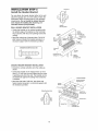
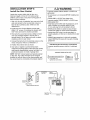
INSTALLATllON
Install
the
Door
STEP
WARNING
6
Control
Toprevent possible SERIOUSINJURYor DEATHfrom
electrocution:
• Be sure power is not connectedBEFOREinstalling door
control
• ConnectONLYto 24 VOLTlow vo]tagewires
Toprevent possibleSERIOUSINJURYor DEATHfrom a
closing garagedoor:
o InstaI_door control within sight 0f garagedoor, out of
reach of children at a minimum height of 5 feet
(15 m), and awayfrom all moving parts of door
• NEVERpermit ch[tdrento operateor play with door
control push buttons or remote control transmitters
. Actiwte door ONLYwhen it can be seenclearfy,is
properly adjusted,and there are no obstructions to door
travel.
• ALWAYSkeepgaragedoor in sight until completely
closed NEVERpermit anyoneto cross path of closing
garagedoor.
Locate door control within sight of door, at a
minimum height of 5 feet (1.5 m) where small
children cannot reach, away from moving parts of
door and door hardware.
1 Strip 1/4" (6 mm) of insulation from one end of bell
wire and connect to the two terminal screws on
back of door control by color: white to 2 and
white/red to 1
2. Fasten the Door Control Button securely with
6ABxlol!2" screws If installing into drywall, drill
5/32" holes and use the anchors provided
3. Run bell wire up wall and across ceiling to motor
unit. Use insulated staples to secure wire in
several places.. Do not pierce wire with a staple,
creating a short or open circuit
4. Connect the bell wire to the terminal screws on the
motor unit panel: white to 2; white/red to 1.
5_Position the antenna wire as shown..
Outside Keylock Accessory Connections
To opener terminal screws: white to 2; white/red
to I..
6. Use tacks or staples to permanently attach
entrapment warning label to wall near door control,
and manual release/safely reverse test labet in a
prominent location on inside of garage door.
HARDWARE SHOWN ACTUAL SIZE
NOTE: DO NOT connect power and operate opener
at this time. The trolley will travel to the furl open
position but will not return to the close position until
the sensor beam is connected and properly aligned..
I_il
2..Conductor
Bell Wire
Screws P',_4,..,_I
(BACK
V_EW)
DOOR
CONTROL
11tH I Ifi I'tili i'i'liTil-_,
Lighted Deer Control Bulton
BUTTON
Back Paeel
of Opener
17
Opener
Terminal
Screws
l,_s,_lal_d
Dqtwal_ Anchors
S|aples
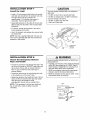
IHSTALLATION
Hnstall
the
STEP
7
Light
To prevent t0ssibleOVERHEATING
of the endpane[or
light socket:
- DO NOTuseshort neck or specialtylight bulbs.
• DO NOTuse halogenbulbs. Use ONLYincandescent
To prevent damageto the opener:
o DO NOTuse bulbs larger than 75W
• ONLYuseA19 size bulbs
o Install a 75 watt maximum light bulb in the sockeL
Light bulb size should be At 9, standard neck only.
The light will turn ON and remain lit for
approximately 4-1/2 minutes when power is
connected. Then the light wig turn OFF
• Apply slight pressure on the sides of the lens and
slide the tabs into the slots in the end panel (See
ittustration)
. To remove, reverse the procedure. Use care to
avoid snapping off lens tabs..
o Use A19, standard neck garage door opener bulbs
for replacement.
Ugh:
Lens
NOTE: Use only a standard light bulb The use of a
short neck or speciality light bulb may overheat the
endpanel or light socket.
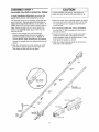
mNSTALLATilON
Attach
Rope
STEP
the Emergency
and Handle
Guide
8
Release
To preventpossible SERIOUSINJURYor DEATHfrom a
falling garagedoor:
, If possible,use emergencyreleasehandleto disengage
trolley ONLYwhen garagedoor is CLOSEDWeak or
broken springs or unbalanceddoor could result in an
open door falling rapidlyand/or unexpectedly
• NEVERuse emergencyreleasehandleunless garage
doorway is dear of persons and obstructions
* NEVERuse handleto pultdoor open or closed If rope
knot becomesuntied, you could fall,
• Thread one end of the rope through the hole in the
top of the red handle so "NOTICE" reads right side
up as shown. Secure with an overhand knot at
least 1" (2..5 cm) from the end of the rope to
prevent slipping.
• Thread the other end of the rope through the hole
in the release arm of the outer trolley,
• Adjust rope length so the handte is 6 feet (I..83 m)
above the floor. Ensure that the rope and handle
clear the tops of all vehicles to avoid
entanglement Secure with an overhand knot.,
Trolley
NOTE: If it is necessary to cut the rope, heat seal
the cut end with a match or lighter to prevent
unraveling.
Trolley
Overhand
Re_ease
18
Handle
Knot
NSTALLATmON
_ENectrical
STEP
9
Requirements
To prevent possible SERIOUSINJURYor DEATHfrom
electrocutionor fire:
To avoid installation difficulties, do not run the
opener at this time.
To reduce the risk of electric shock, your garage door
opener has a grounding type ptug with a third
grounding pin This plug will only fit into a grounding
type outlet If the plug doesn't fit into the outlet you
have, contact a qualified electrician to install the
proper outlet
- Besure power is not connectedto the opener,and
disconnect powerto circuit BEFOREremoving coverto
establishpermanentwiring connection
• Garagedoor installationand wiring MUSTbe in
compliancewith ail local electricaland buiiding codes
o NEVERusean extensioncord, 2-wire adapter,or
changeplug in any wayto makeit fit outlet Be sure
the openeris grounded:
PERMANENT
CONNECTION
WIRING
GroundTab
If permanent wiring is required by your local
code, refer to the following
procedure.
Green
Graun_
S_ew
To make a permanent connection through the 7/8"
hole in the top of the motor unit:
• Remove the motor unit cover screws and set the
cover aside,
- Remove
the attached
3-prong
cord
Whi_
- Connect the black (line) wire to the screw on the
brass terminal; the white (neutral) wire to the
screw on the silver terminal; and the ground wire
to the green ground screw The opener must be
grounded.
• Reinstall
the cover,
To avoid installation
opener at this time.
difficulties,
do not run the
19
Black
W_re
UNSTALLAT|OH
Install
The
Protector
STEP
10
System
_
Besure power is not connectedto the garage door
openerBEFOREinstalling the safetyreversing sensor
To preventSERIOUSINJURYor DEATHfrom a closing
garagedoor:
, Correctlyconnectand align the safety reversing
sensor This required safetydevice MUSTNOTbe
disabled
The safety reversing sensor must be connected
and aligned correctly before the garage door
opener wilt move in the down direction.
IMPORTANT INFORMATION ABOUTTHE SAFETY
REVERSING SENSOR
• Install the safety reversingsensor so beamis NO
HIGHERthan 6" (15 cm) abovegaragefloor
When properly connected and aligned, the sensor
will detect an obstacle in the path of its electronic
beam, The sending eye (with an amber indicator
tight) transmits an invisible light beam to the
receiving eye (with a green indicator light),, If an
obstruction breaks the light beam while the door is
closing, the door wilt stop and reverse to full open
position, and the opener tights will flash 10 times,
If it is necessary to mount the units on the walt, the
brackets must be securely fastened to a solid
surface such as the wall framing, Extension brackets
(see accessories) are available if needed If
installing in masonry construction, add a piece of
wood at each location to avoid drilling extra holes in
masonry if repositioning is necessary.
The units must be instafied inside the garage so that
the sending and receiving eyes face each other
across the door, no more than 6" (15 cm) above the
floor, Either can be installed on the left or right of the
door as long as the sun never shines directly into the
receiving eye Ions,
The invisible light beam path must be unobstructed
No part of the garage door (or door tracks, springs,
hinges, rollers or other hardware) may interrupt the
beam while the door is closing
"The mounting brackets are designed to clip onto the
track of sectional garage doors without additional
hardware
Safer,
Sensor
6" (15 cm) max above floor
levistble Ugbt Beam
Protection Area
Facing the door from inside the garage
20
INSTALLING
THE BRACKETS
Figure
Be sure power to the opener is disconnected.
Install and align the brackets so the sensors wilt face
each other across the garage door, with the beam no
higher than 6" (t5 cm) above the floor They may be
installed in one of three ways, as follows.
DOOR
3__
TRACK
MOUNT
(RIGHT
SIDE)
Door
Track
indicator
Garage
door track
installation
(preferred):
= Slip the curved arms over the rounded
each door track, with the curved arms
door Snap into place against the side
It should lie flush, with the lip hugging
edge of the track, as shown in Figure
Light
edge of
facing the
of the track
the back
1.
I
//
Senso, _
Bracket
If your door track will not support the bracket
securely, wall instalfation is recommended
Wall installation
(Figure
2 & 3):
_i_"
Figure 2 I
* Place the bracket against the wall wlh curved
arms facing the door Be sure there is enough
clearance for the sensor beam to be unobstructed
WALL
I
MOUNT
(RIGHT
S_DE)
Fasten Wood B!ock to Wall wth
Lag
Screws
(Not
Provided)
- If additional depth is needed, an extension bracket
(See Accessories) or wood blocks can be used
• Use bracket mounting holes as a template to
locate and ddl (2) 3116" diameter pilot holes on
the wall at each side of the door, no higher than
6" (15 cm) above the floo_,
- Attach brackets to wall with tag screws
(Not provided),,
- If using extension brackets or wood blocks, adjust
right and left assemblies to the same distance out
from the mounting surface, Make sure all door
hardware obstructions are cleared,
Floor installation
i-
°IProvided)
(Figure 4):
o Use wood blocks or extension brackets (See
Accessories) to elevate sensor brackets so the
lenses will be no higher than 6" (15 cm) above the
floor,
• Carefully measure and place right and left
assembles at the same distance out from the wall.,
Be sure all door hardware obstructions are
cleared,
- Fasten to the floor with concrete
shown,
anchors as
Figure 4
HARDWARE
FLOOR
MOUNT
(RIGHT
SIDE)
i
SHOWN ACTUAL SIZE
•
_.r_'
,311
Concrete
,
i
'
Anchors
(Not Pro',4ded)
Lens ',
_'_f"/_
Cania!_Sot
WingNut
I/4"-20xl/2"
114"-20
Stapfes
21
Indicator
MOUNTING AND WIRING
REVERSING SENSORS
THE SAFETY
Figure
5
Wing Nut
, Slide a t/4"-20xl/2"
carriage bolt head into the slot
on each senso_ Use wing nuts to fasten sensors to
brackets, with lenses pointing toward each other
across the door Be sure the fens is not obstructed
by a bracket extension (Figure 5)
,, Finger tighten the wing nuts.
= Run the wires from both sensors to the opener Use
insulated staples to secure wire to wall and ceiling.
TROUBLESHOOTING
SENSORS
, Strip 1/4" (6 ram) of insulation from each set of
wires.. Separate white and white/black wires
sufficiently to connect to the terminal screws: white
to 2 and whitetb]ack to 3 (Figure 6).
THE SAFETY
REVERSING
I. If the sending eye indicator light does not glow
steadily after installation, check for:
° Electric power to the opener
° A short in the white or white!black
ALIGNING THE SAFETY REVERSING SENSORS
can occur at staples,
° Plug in the opener: The indicator lights in both the
sending and receiving eyes will glow steadily if
wiring connections and alignment are correct
wires, These
or at opener connections.
• Incorrect wiring between
° A broken wire.
sensors and opener.
2 If the sending eye indicator light glows steadily but
the receiving eye indicator light doesn't:
The sending eye amber indicator light will glow
regardless of alignment or obstruction If the green
indicator light in the receiving eye is off, dim, or
flickering (and the invisible light beam path is not
obstructed), alignment is required,,
• Check alignment
- Check for an open wire to the receiving
3 If the receiving
either sensor.
• Loosen the sending eye wing nut and readjust,
aiming directly at the receiving eye,, Lock in place,
eye indicator
NOTE: When the invisible beam path is obstructed
or misaligned while the door is closing, the door will
reverse.. If the door is already open, it will not close
The opener lights will blink 10 times. See page 20..
, Loosen the receiving eye wing nut and adjust
sensor until it receives the sender's beam, When
the green indicator light glows steadily, tighten the
wing nut,
Connect Wire _o
Figure
Termtnat
6
..
Screws
/
Bell Wire
Boor
Control
Sensor
Connec_Jons_
(dolled
line)
Connections
_'_'_,*.
OPENER
invisible Lighl Beam
Protection Area
Safety
Reversing
eye.
light is dim, realign
Sensor
Safety Reversing Sensor
22
.
TERMINAL
"_
SCREWS
NSTALLATmON
Fasten
the
Door
STEP
i CAUTBON
t t
Bracket
Fiberglass,aluminum or lightweightsteel garagedoors
WILL REQUIREreinforcementBEFOREinstallationof
door brackeLContactyour door manufacturerfor
reinforcementkit
Follow instructions which apply to your door type
as illustrated below or on the following page..
A horizontal
reinforcement
brace should be long
enough to be secured to two vertical supports.
A
vertical reinforcement
brace should cover the
height of the top panel.
HARDWARE SHOWN ACTUAL SIZE
The illustration shows one piece of angle iron as the
horizontaf brace.. For the vertical brace, two pieces of
angle iron are used to create a U-shaped support
(Figure 1). The best solution is to check with your
garage door manufacturer for an opener installation
door reinforcement kit.
Nut 5115"q8
NOTE: Many vertical brace installations provide for
direct attachment of the clevis pin and door arm tn
this case you will not need the door bracket; proceed
to Installation Step 12.
LockWasher
51_6'
Carriage
Bo]!
5!16"-t 8x2-1/2"
SECTIONAL BOORS
- Center the door bracket on the previously marked
vertical centerfine used for the header bracket
installation. Note correct UP placement, as
stamped inside the bracket (Figure 2)
° Position the bracket on the face of the door within
the following limits:
. Mark and drill 5/16" left end right fastening holes..
Secure the bracket as shown in Figure 1 if there is
vertical reinforcement.
If your installation doesn't require verticai
reinforcement but does need top and bottom
fastening holes for the door bracket, fasten as shown
in Figure 2
A) The top edge of the bracket 2"-4" (5-10 cm)
below the top edge of the door
B) The top edge of the bracket directly below any
structural support across the top of the door.
Header
Bracket
Horizontal and vertical reinforcement
is needed for lightweight
garage doors
doors w_th
Figure 1
Figure
23
2
ONE-PIECE
DOORS
PTease read and comply with the warnings and
reinforcement
instructions on the previous page
They apply to one-piece doors also,,
. Center the door bracket on the top of the door, in
line with the header bracket as shown Mark either
the left and right, or the top and bottom holes
- Drii! 5/16" pilot holes and fasten the bracket with
hardware supplied.
If the door has no exposed framing, drill 3/16" pilot
holes and fasten the bracket with 5/I6"x1-1/2" tag
screws (not provided) to the top of the door
HARDWARE
Nut
SHOWN ACTUAL SiZE
5116_q8
Lock
Washer
5116"
NOTE: The door bracket may be installed on the top
edge of the door ff required for your installation
(Refer to the dolted line optional placement drawing)
Drill 3/16" pilot holes and substitute 5/16"xt-1/2" lag
screws (not provided) to fasten the bracket to the
door.
Horizontal and verticat
reinforcement is needed for
._doors
(fibergtass_ alumtnttm_ steel,
deer wffh grass panet, ere.)..
(Not Provided)
Door
Bracket
Oplional
Placement
of Door
Bracket
Vertical
of Garage
Door
Door
Top Edge
of Door
Optionaf
Placement
Carriage Bolt
For a doer with no exposed framing.
Or for the optional installation, use
5/16"x1-1/2" Iag screws (Not Provided)
to fasten door brackeL
24
5/t6'-18x2q/2"
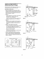
IHSTALLATllON
Connect
Door
STEP
Arm
to
12
Trolley
Follow instructions which apply to your door type as
illustrated below and on the following page
SECTIONAL DOORS ONLY
• Make sure garage door is fully closed Pull the
emergency release handle to disconnect the outer
trolley from the inner trolley Slide the outer trolley
back (away from the pulley) about 8" (20 cm) as
shown in Figures l, 2 and 3,
. Figure 1:
- Fasten straight door arm section to outer trolley
with the 5/16"x1" clevis pin., Secure the
connection with a ring fastener
- Fasten curved section to the door bracket in the
same way, using the 5/16"xl-1/4" clevis pin
Clevis
Pin
5J16"x1-1/4'
Figure
1
. Figure 2:
Pulley
- Bring arm sections together. Find two pairs of
holes that line up and join sections. Select holes
as far apart as possible to increase door arm
rigidity.,
o Figure 3, Hole alignment alternative:
- If holes in curved arm are above holes in straight
arm, disconnect straight arm= Cut about 6"
(15 cm) from the solid end_ Reconnect to trolley
with cut end down as shown.,
- Bring arm sections together.
- Find two pairs of holes that line up and join with
bolts, lock washers and nuts.,
>Bolts
5t_ 6_.,18x7/8"
• Pull the emergency release handle toward the
opener at a 45° angle so that the trolley release
arm is horizontal. Proceed to Adjustment Step 1,
page 27 Trolley will re-engage automatically when
opener is operated,
Door
Figure
Bracket
2
Pulley
! :_.
HARDWARE
SHOWN
ACTUAL
©
Lock Washer
Clevis Pin
5/! 6"xl" (Trolley}
51t6"
l/4'(DoorBracket}
Losk
., .
R_ng Fastener
Cievis Pin
5116'xt
8" (20 em_, rnfn _,)j:
SIZE
/_/
Washc#s/_/
Nuts
_1_:"
707
°1
Hex Bo_t
5!16"-18x7,"8"
o(_
Figure 3
25
_
CUt this
end
ALL ONE-PIECE
DOORS
Door
1.Assemble the door arm, Figure 4:
_'_
|_'__
• Fasten the straight and curved door arm sections
together to the longest possible length (with a 2
or 3 hole overlap)
• With the door closed, connect the straight door
arm section to the door bracket with the
5/16"x1-1/4" clevis pin.
• On one-piece doors, before connecting the door
arm to the troBey,the travel limits must be
adjusted. Limit adjustment screws are located on
the left side panel as shown on page 27. Follow
adjustment procedures below.
- Turn the UP limit adjustment screw
counter-clockwise 4 turns.
- Close the door and join the curved arm to the
connector hole in the trolley with the remaining
clevis pin.. It may be necessary to ]ift the door
slightfy to make the connection
- Manually raise the door to the open position
(parallel to the floor), and lift the door arm to the
trolley The arm should touch the trolley just in
back of the door arm connector hole. Refer to
the fully open trolley/door arm positions in the
illustration.If the arm does not extend far
enough, adjust the limit further.. One full turn
equals 2" (5 cm) of trolley travel
Figure
5
DoorArm
3. Connect the door arm to the trolley:
- Press the Door Control push button. The trolley
witt travet to the fully open position
o Secure with a ring fastener
o Run the opener through a complete travel cycle.
If the door has a slight "backward" slant in full
open position as shown in the illustration,
decrease the UP limit until the door is paralle] to
the floor
NOTE: When setting the up limit on the following
page, the door should not have a "backward" slant
when fully open as illustrated below A slight
backward slant will cause unnecessary bucking
and!or jerking operation as the door is being opened
or closed from the fully open position
decrease DOWN
- Turn the DOWN limit adjustment
clockwise 4 complete turns,
Nots
5/;6"-18
- Manually close the door and lift the door arm to
the trolley. The arm should touch the trolley just
ahead of the door arm connector hole Refer to
the fully closed trolley/door arm positions in the
illustration If the arm is behind the connector
hole, adjust the limit further= One full turn equals
2" (5 cm) of trolley travel
decrease UP travel
* Closed door adjustment:
travel limit
Lock
- Press the Door Control push button The trolley
wilf travel to the fully closed position
procedures, Figure 5:
• Open door adjustment:
limit
Fas'_'er_er
_%-_._
Figure 4
• Secure with a ring fastener.
2. Adjustment
"_'9.._--_
"
screw
_nner Trolley
,_--
Emergeflcy
Release
Handle
Ouler
Trotley
Correct Angle
B ack'war_
Open Door
(Incorrect)
26
Slant
ADJUSTMENT
Adjust
Limits
the
STEP
UP and
t
DOWN
Travel
Without a properlyinstalledsafety reversalsystem,
persons (particularlysmall children) could be
SERIOUSLY
INJUREDor KILLEDby a closing garage
door
Limit adjustment settings regulate the points at which
the door will stop when moving up or down.
- Incorrect adjustment of garagedoor travel limits wilt
interfere with proper operationof safety reversal
system,
- if one control (force or travel limits) is adjusted,the
other control may also need adjustment
• After ANYadjustmentsare made,the safety reversal
system MUSTbe tested Door MUSTreverseon
contact with 1-1f2"high (3,8 cm) object (or 2x4 laid
fiat) on floor
To operate the opener, press the Door Control push
bar. Run the opener through a complete travel cycle.
, Does the door open and close completely?
• Does the door stay closed and not reverse
unintentionally when fully closed?
If your door passes both of these tests, no limit
adjustments are necessary unless the reversing test
fails (Adjustment Step 3, page 29)
Adjustment procedures are outlined below. Read the
procedures carefully before proceeding to
Adjustment Step 2 Use a screwdriver to make limit
adjustments. Run the opener through a complete
travel cycle after each adjustment.
CAUTION
To preventdamageto vehicles,be sure fully open door
providesadequateclearance
NOTE: Repeated operation of the opener during
adjustment procedures may cause the motor to
overheat and shut off Simply wait 15 minutes and
try again ff anything interferes with the door's
upward travel, it will stop. If anything interferes with
the door's downward travel (including binding or
unbalanced doors), it will reverse
HOW AND WHEN TO ADJUST
°ff
]
Cover
Prolectlon
Bolt
THE LIMITS
the door does not open completely
at least five feet (1.5 m):
I
but opens
Lell
Side Panel
V
Umil Adfuetmenl
Screws
Increase up travel Turn the UP fimit adjustment
screw clockwise, One turn equals 2" (5 cm) of
travel,
NOTE: To prevent the trolley from hitting the cover
protection bolt, keep a minimum distance of
2-4" (5 cm - 10 cm) between the trolley and the
bolt,
ADJUSTMENT
IJ_BEL
• ff door does not open at least 5 feet (1.5 m):
Adjust the UP (open) force as explained
Adjustment Step 2
in
ff the door reverses when closing and there is
no visible interference to travel cycle:
• ff the door does not close completely:
Increase down travel Turn the down Fimit
adjustment screw counterclockwise,
equals 2" (5 cm) of travel,
if the opener lights are flashing, the Safety
Reversing Sensors are either not installed,
misafigned, or obstructed. See Troubleshooting,
page 22
One turn
If door still won't close completely and the trolley
bumps into the pulley bracket (page 4), try
lengthening the door arm (page 25) and
decreasing the down limit
• ff the opener
reverses
in fully
closed
Test the door for binding: Pull the emergency
release handle. Manually open and close the door.
If the door is binding or unbalanced, call for a
trained door systems technician tf the door is
balanced and not binding, adjust the DOWN
(close) force. See Adjustment Step 2.
position:
Decrease down travel, Turn the down limit
adjustment screw clockwise, One turn equals
2" (5 cm) of travel
27
]
|
J
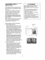
ADJUSTMENT
Adjust
the
STEP
2
Force
Without a properlyinstalled safety reversalsystem,
persons (particufariysmall children)could be
SERIOUSLY
INJUREDor KILLEDby a ctesing garage
door
• Too much force on garagedoor will interfere with
proper operationof safety reversatsystem
• NEVERincreaseforce beyondminimum amount
requiredto close garagedoor
• NEVERuseforce adjustmentsto compensatefor a
binding or sticking garagedoor
• if one control (force or travel limits) is adjusted,the
other control may also need adjustment
• After ANYadjustmentsare made,the safety reversal
system MUSTbe tested Door MUSTreverseon
contactwith 1-It2" high (38 cm) obiect (or 2x4 laid
fiat) on floor
Force adjustment controls are located on the back
panel of the motor unit. Force adjustment settings
regulate the amount of power required to open and
close the door
If the forces are set too light, door travel may be
interrupted by nuisance reversals in the down
direction and stops in the up direction. Weather
conditions can affect the doer movement, so
occasional adjustment may be needed
The maximum force adjustment range is about
3/4 of a complete turn° Do not force controls
beyond that point. Turn force adjustment controls
with a screwdriver
NOTE: If anything interferes with the door's upward
travel, it will stop.. If anything interferes with the
door's downward travel (including binding or
unbalanced doors), it will reverse.
HOW AND WHEN TO ADJUST THE FORCES
1. Test the DOWN (close) force
Fome Adjustment
Controls
- Grasp the door bottom when the door is about
halfway through DOWN (close) travel.. The door
should reverse. Reversal halfway through down
travel does not guarantee reversal on a 1-1/2"
(3.8 cm) obstruction. See Adjustment Step 3,
page 29. If the door is hard to hold or doesn't
reverse, DECREASE the DOWN (close) force by
turning the control counterclockwise.. Make small
adjustments untii the door reverses normally
After each adjustment, run the opener through a
complete cycle.
- If the door reverses during the down (close)
cycle and the opener lights aren't flashing,
INCREASE DOWN (close) force by turning the
control clockwise, Make small adjustments until
the door completes a close cycle_After each
adjustment, run the opener through a complete
travel cycle.. Do not increase the force beyond the
minimum amount required to close the door.
E:::::::3
ADJUSTMENT
LABEL
2. Test the UP (open) force
. Grasp the door bottom when the door is about
halfway through UP (open) travel The door
should stop.. If the door is hard to hold or
doesn't stop, DECREASE UP (open) force by
turning the control counterclockwise, Make smatl
adjustments until the door stops easily and opens
fully. After each adjustment, run the opener
through a complete travei cycle..
• If the door doesn't open at least 5 feet (1.5 m),
INCREASE UP (open) force by turning the
control clockwise.. Make sma!i adjustments untit
door opens completely Readjust the UP limit if
necessary. After each adjustment, run the opener
through a complete travef cycle.
Open Force
28
CIose Fo:ree
ADJUSTMENT
Test
the
STEP
Safety
3
Reversal
System
Without a properlyinstalled safety reversa]system
persons (particularlysmalt children) could be
SERIOUSLYINJUREDor KILLEDby a closing garage
door"
TEST
• With the door fully open, place a 1-1/2" (38 cm)
board (or a 2x4 laid fiat) on the floor centered
under the garage door
• Safetyreversalsystem MUSTbe tested every month
. If one control (force or travel limits) is adjusted the
other control may also need adjustment
. After ANYadjustmentsare made,the safety reversa]
system MUSTbe tested Door MUSTreverseon
contact with 1-I12" high (38 cm) object (or 2x4 laid
fiat) on the floor
• Operate the door in the down direction The door
must reverse on striking the obstruction
ADJUST
. If the door stops on the obstruction it is not
traveling far enough in the down direction
Increase the DOWN limit by turning the DOWN
limit adjustment screw counterclockwise 1/4 turn
NOTE: On a sectional door, make sure limit
adjustments do not force the door arm beyond a
straight up and down position See the illustration
on page 25
• Repeat the test
• When the door reverses on the 11/2" (38 cm)
board, remove the obstruction and run the opener
through 3 or 4 comp]ete travel cycles to test
adjustment
° If the unit continues to fail the Safety Reverse Test
call for a trained door systems technician
IMPORTANT
SAFETY
Test the Safety Reverse
o Each adjustment
force controls
CHECK:
System
after:
of door arm length, limits, or
*
"(
B cm) board
(or a 2x4 laid feat)
o Any repair to or adjustment of the garage door
(including springs and hardware)
• Any repair to or buckling
of the garage floor
o Any repair to or adjustment
of the opener
__
ADJUSTMENT
Test
The
Protector
STEP
:
___
z
4
System
s
Without a properly installed safety reversingsensor
persons (particularlysmall children) could be
SERIOUSLYINJUREDor KILLEDby a closing garage
door
- Press the remote control push button to open the
door
• Place the opener carton in the path of the door
, Press the remote control push button to close the
door The door will not move more than an inch
(25 cm), and the opener lights will flash
The garage door opener will not close from a remote
if the indicator light in either sensor is off (alerting
you to the fact that the sensor is misaligned or
obstructed)
If the opener closes the door when the safety
reversing sensor is obstructed (and the sensors
are no more than 6" (15 cm) above the floor), call
for a trained door systems technician
29
OPERATmON
i
i
i
llll
i
IMPORTANT
i
=
SAFETY ,NSTRUCTIONS
To reduce the risk of SEVERE
1. READAND FOLLOWALL WARNINGSAND
INSTRUCTIONS
2 ALWAYSkeepremote controls out of reach of children.
NEVERpermit children to operateor play with garage
door contro_push buttons or remotecontrols
3. ONLYactivategaragedoor when it can be seenctearly,it
is properly adiusted,and there are no obstructionsto
door travel.
4. ALWAYSkeepgaragedoor in sight unti! completely
closed. NOONESHOULDCROSSTHEPATHOF]HE
MOVINGDOOR
5. NOONESHOULDGOUNDERA STOPPED,PARTIALLY
OPENEDDOOR.
6 if possible, useemergencyreleasehandieto disengage
trolley ONLYwhen garagedoor is CLOSEDWeakor
brokensprings or unbalanceddoor could result in an
open door failing rapidly and/or unexpectedly
7. NEVERuseemergencyreleasehandleunless garage
doorway is clearof persons and obstructions
8. NEVERusehandle to pull garagedoor open or closed if
rope knot becomesuntied,you couidfall.
Using
Your
Garage
Door
=
iNJURY or DEATH:
g. if one control (force or travel limits) is adjusted,the
other control may also needadiustment
l& After ANYadjustmentsare made,the safety reversal
system MUSTbe tested
tl. Safetyreversaisystem MUSTbe tested every month.
Garagedoor must reverseon contact with 1-1/2" high
(3 8 cm) object (or a 2x4 laid flat) on the floor
12, ALWAYSKEEPGARAGEDOORPROPERLYBALANCED
(seepage3) An improperly balanceddoor may not
reversewhen required and could result in SEVERE
iNJURYor DEATH_
13. Ali repairsto canes, spring assembliesand other
hardware,all of which are under EXTREMEtension,
MUSTbe madeby a trained door systems technician
14. ALWAYSdisconnectelectricpowerto garagedoor
openerBEFOREmaking any repairsor removing
covers.
SAVETHESEINSTRUCTIONS.
6, If obstructed while opening, the door will stop.
7. If fully open, the door will not close when the beam
is broken. The sensor has no effect in the opening
cycle
If the sensor is not installed, or is misaligned, the
door won't close from a hand-held remote. However,
you can close the door with the Door Control, the
Outdoor Key Switch, or Keyless Entry, ffyou activate
them until down travel is complete If you release
them too soon, the door will reverse.
Opener
Your Security+ _ opener and hand-held remote
control have been factory-set to a matching code
which changes with each use, randomly accessing
over 100 billion new codes. Your opener will operate
with up to eight Security÷ _ remote controls and one
Security÷ _ Keyless Entry System. If you purchase a
new remote, or if you wish to deactivate any remote,
follow the instructions in the Programming section.
Activate your opener with any of the following:
. The hand-held Remote Control,:'Hold the large
push button down until the door starts to move
• The wall-mounted Door Control,: Hold the push
button or bar down until the door starts to move.
The opener lights will turn on under the following
conditions: when the opener is initially plugged in;
when power is restored after interruption; when the
opener is activated
They will turn off automatically after 4-1/2 minutes
Bulb size is A19. Bulb power is 75 watts maximum.
• The Keyless Entry (See Accessories): If provided
with your garage door opener, it must be
programmed before use_See Programming..
When the opener is activated (with the safety
reversing sensor correctly installed and aligned)
1..If open, the door wil! close. If closed, it will open.
2..If closing, the door wil! reverse.
3. If opening, the door will stop
4 If the door has been stopped in a partially open
position, it will close.
5. If obstructed while closing, the door will reverse., if
the obstruction interrupts the sensor beam, the
opener lights will blink for five seconds.
3O
Using
the Wall-Mounted
Door Control
To Open
Press the push button to open or close the
door, Press again to reverse the door
during the closing cycle or to stop the door
while it's opening
the
Door
Manually
To preventpossible SERIOUSINJURYor DEATHfrom a
falling garagedoor:
. If possible,use emergencyreleasehandleto
disengagetrolley ONLYwhen garagedoor is CLOSED
Weakor broken springs or unbalanceddoor could
result in an open door faliing rapidly and/or
unexpectedly,
. NEVERuse emergencyreleasehandleunless garage
doorwayis clear of persons and obstructions,
• NEVERuse handfeto putt door open or closed if rope
knot becomesuntied, you couid fall
DISCONNECT THE TROLLEY:
The door should be fuJly closed if possible, Pu]t down
on the emergency release
Trolley
handle (so that the trolley
f
'
release arm snaps into a
vertical position) and lift the
door manualiy The lockout
feature prevents the trolley
Release Arm
from reconnecting
(In Manual
Discoe nt.'_;t
automatically, and the door
Position)
can be raised and lowered
manually as often as
necessary,
Lockout position
(Manual disconnect)
TO RE-CONNECT
TROLLEY:
THE
Pull the emergency release
handle toward the opener
at an angle so that the
trolley release arm is
horizontal The trolley will
reconnect on the next UP
or DOWN operation, either
manualiy or by using the
door control or remote
T_olley
Release
Arm
(In Manual
Dlscoe
n_,_[
POsition)
To reconnect
31
THE REMOTE
CARE
DOOR
OF YOUR
OPENER
LIMIT AND FORCE
ADJUSTMENTS:
Weather conditions may
cause some minor changes
in door operation requiring
some re-adjustments,
particularly during the first
year of operation,
BATTERY
To prevent possible SERIOUSINJURYor DEATH:
• NEVERallow small children near batteries,
FORCECONTROLS
- If battery is swallowed,immediately notify doctor
The lithium battery should
produce power for up to
5 years, To replace battery,
use the visor clip or
screwdriver blade to pry open
the case as shown Insert
battery positive side up (+),,
LIMITCONTROLS
Pages 27 and 28 refer to the
@[ @3_@_
limit and force adjustments
Only a screwdriver is
required Follow the instructions carefully,
Repeat the safety reverse test (Adjustment
Step 3, page 29) after any adjustment
of limits
force.
MAINTENANCE
CONTROL
GARAGE
Dispose of old battery properly,
or
NOTICE: To cornp]y wiih FCC and or Induslry Cartad_ rules (It}, a,dj_;Iment or
modifi_[f_ns
of this receivor and/or tr;nomit[ei" _ro t}rDhib_ed, except for cha_gi_g the
code soilint] or _opladng tho b_tler/THERE
ARE NO OTHER USER S_RVICEABLE PARTS
Tasted to Compiy with FCC S'._ndards FOR ROME OR OFFICE USE. Oper_Jon is eubje c'_to
lho IotlovAng lw_ cor_dilions: {1} this dev_co may not caus_ t_fmleI ielorf_ronce, a_ld
_2) _his doviee m_J_ _coopt ar_y tntedor_oce received, tncludin_ int_Rer_nce that may
SCHEDULE
c_es_ e_dos red ope_t
Once a Month
• Manually operate door, If it is unbalanced or
binding, call a trained door systems technician,,
• Check to be sure door opens & closes fully, Adjust
limits and/or force if necessary, (See pages 27
and 28,)
• Repeat the safety reverse test Make any
necessary adjustments. (See Adjustment Step 3 )
Twice a Year
- Check chain tension=, Disconnect trolley first.
Adjust if necessary (See page tl),
Once a Year
• Oil door rollers, bearings and hinges, The opener
does not require additional lubrication,1 Do not
grease the door tracks
32
r,n
HAVIHG
A PROBLEM?
1.My door will not close
on my motor unit: The
must be connected and
tile garage door opener
direction
and the light bulbs blink
safety reversing sensor
aligned correctly before
will move in the down
Bell V_fire
\
- Verify the safety sensors are properly installed,
aligned and free of any obstructions. Refer to
InstallationStep 10:'Instafl The Protector
SysterrP.
• Check diagnostic LED for flashes on the motor
unit then refer to the Diagnostic Chart on the
following page.
2f My remotes will not activate the door:
Safety
Reversing
Sensor
• Reprogram remotes following the programming
instructions. Refer to Programming
• if remote will still not activate your door, check
diagnostic LED for flashes on motor unit then
refer to Diagnostic Chart on the following page
Seeding Eye S_fety Reversing
Sensor (Amber Indicator Light)
3. My door reverses for no apparent reason:
Repeat safety reverse test after adjustments to
force or travel limits The need for occasional
adjustment for the force and limit settings is
normal. Weather conditions in particular can affect
door travel
Receiving Eye Safety Reversing
Sensor (Green Indicator Ught)
J
5. My motor unit hums briefly:
- First verify that the trolley is against the stop bolt.
o Release the door from the opener by pulling the
Emergency Release Rope.
= Manually check door for baiance or any binding
problems
• Manually bring the door to a closed position
° Refer to Adjustment Step 2, Adjust the Force.
• Loosen the chain by adjusting the outer nut 4 to
5 turns= This relieves the tension
4. My door reverses for no apparent reason after
fully closing and touching the floor: Repeat
safety reverse test after adjustments to force or
travel limits..The need for occasional adjustment
for the force and limit settings is normal. Weather
conditions in particular can affect door travel
Run the motor unit from the remote control or
door control, The trolley should travel towards
the door and stop. If the trolley re-engages with
the door, pull the Emergency Release Rope to
disengage.
Decrease the UP travel by turning the UP Travel
adjustment screw 2 fult turns away from
the arrow.
, Refer to Adjustment Step 1, Adjust the UP and
DOWN Travel Limits. Decrease down travel by
turning down limit adjustment screw clockwise
Re-tighten the outer nut so the chain is a
t/2" (13 mm) above the base of the rail (When
the door is reconnected and closed, the chain
will sag. This is normaL)
If the trolley does not move away from the bolt,
repeat the steps above.
33
Bell W_e
Your garage door opener is programmed with
self-diagnostic capabilities. The "Learn" button!diagnostic
LED will flash a number of times then pause signifying it
has found a potential issue. Consult Diagnostic Chart below.
Diagnostic
Chart
®
Safety reversing sensors
wire open (broken or
disconnected).
Symptom: One or both
not glow steady.
of the Indicator
lights
on the safety
sensors
do
- Inspect sensor wires for a short (staple in wire), correct wiring polarity
(blackJwhite wires reversed), broken or disconnected wires, replace/attach
as needed.
OR
• Disconnect
all wires from back of motor unit
- Remove sensors from brackets and shoden sensor wires to 1-2 ft
(30-60 cm) from back each of sensor
- Reattach sending eye to motor unit using shortened wires
indicator light glows steadily, attach the receiving eye.
Safety reversing sensors
wire shorted or
black/white wire
reversed,
or
Symptom: LED is not lit on door control.
- inspect door control/wires for a short (staple in wire), replace as needed.
. Disconnect wires at door control, touch wires together If motor unit
activates, replace door control
= If motor unit does not activate, disconnect door control wires from motor
unit Momentarily short across red and white terminals with jumper wire.
If motor unit activates, replace door control wires.
Symptom: Sending indicator
light is dim or flashing.
Safety reversing sensors
slightly misaligned
(dim or flashing LED).
Motor overheated
or
possible
RPM sensor
failure. Unplug to reset.
eye
• Align sensors, if the indicator lights glow replace the wires for the sensors.
If the sensor indicator lights do not light, replace the safety sensors.
0
Door control
wire shorted.
If sending
• Realign receiving
light glows steadily, receiving
indicator
eye sensor, clean lens and secure brackets
• Verify door track is firmIy secured
to wall and does not move.
Symptom: Motor has overheated; the motor unit does not operate or
trolley is stuck on stop bolt = Motor unit hums briefly; RPM Sensor =
Short travel 6_8" (15_20 cm),
- Unplug unit to reset
- If it is still flashing
RPM sensor.
Try to operate motor unit, check diagnostic
code.
5 times and motor unit moves 6-8" (15-20 cm), replace
. If motor unit does not operate, motor unit is overheated.. Wait 30 minutes
and retry.. If motor unit still wil! not operate repIace logic board
Symptom:
Motor Circuit Failure,
Replace Receiver
Logic Board.
. Replace
Motor unit does not operate.
logic board because
34
motor rarely fails.
PROGRAMMING
NOTICE: If this Security_
garage door opener is operated with a non-rolling code transmitter, the technical
measure in the receiver of the garage door opener, which provides security against code-theft devices, will be
circumvented.
The owner of the copyright in the garage door opener does not authorize the purchaser or
supplier of the non-rolling cede transmitter to circumvent that technical measure.
Your garage door opener has already been programmed at the factory to operate with your hand-held remote
control, The door will open and close when you press the large push butlon.
Below are instructions for programming your opener to operate with additional Security+ _ remote controls=
To Add
USING THE "LEARN"
or Reprogram
a Hand.held
Remote
Control
BUTTON
To Erase
All
Codes
Unit
From
Motor
Memory
To deactivate any unwanted remote,
first erase all codes:
Press and hold the "learn" button on
motor unit until the leam indicator
light goes out (approximately 6 seconds). All previous
codes are now erased Reprogram each remote or
keyless entry you wish to use
*3.Function
If provided with your garage door opener, the large
button is factory programmed to operate it. Additional
buttons on any
Security+ = 3-Function
remote or compact
remote can be
programmed to operate
other Security+ e garage
door openers.
1 Press and release the "learn"
button on the motor unit The
learn indicator light wilf glow
steadily for 30 seconds,
2 Within 30 seconds, press and
hold the button on the handheld remote* that you wish to
operate your garage door,
3 Release the button when the
motor unit lights blink. It has
learned the code, If light bulbs
are not installed, two clicks will
be heard,
Remotes
...]
/
35
To
Add,
Reprogram
or
NOTE: Your new Keyless Entry must be programmed
USING THE "LEARN"
Change
a Keyless
Entry
to operate your garage
PiN
door opener.
BUTTON
To change
an existing,
known
PIN
If the existing PIN is known, it may be changed
one person without using a [adder
by
1. Press the four buttons for the present PIN, then
press and hold the # button
The opener
button..
light will blink twice
Release the #
2, Press the new 4-digit PIN you have chosen, then
press Enter,
The motor unit Iights will blink once when the PIN
has been ]earned,,
Test by pressing the new PIN, then press Enter: The
door should move,,
1. Press and release the "learn"
button on motor unit The learn
indicator light will glow steadily
for 30 seconds.
To set a temporary PiN
You may authorize access by visitors or service
people with a temporary 4-digit PIN. After a
programmed number of hours or number of
accesses, this temporary PIN expires and wilt no
longer open the door. It can be used to close the
door even after it has expired. To set a temporary
PIN:
2 Within 30 seconds, enter a four
digit personal identification
number (PIN) of your choice on
the keypad Then press and
hold the ENTER button.
1, Press the four buttons for your personal entry PIN
(not the last temporary PIN), then press and hold
the "[" button,
3, Release the button when the
motor unit lights blink It has
learned the code. If light bulbs
are not installed, two ct[cks will
be heard.
The opener light will blink three times, Release the
button,
2 Press the temporary 4-digit PIN you have chosen,
then press Ente_
One Button Close
The opener light wili blink four times°
3, To set the number of hours this temporary PIN will
work, press the number of hours (up to 255), then
press ;_.,
OR
Opener can be closed by pressing only the ENTER
button if the one button close feature has been
activated This feature has been activated at the
3. To set the number of times this temporary PIN will
work, press the number of times (up to 255), then
press #.
factory.. To activate or deactivate this feature press
and hold buttons 1 and 9 for 10 seconds The
keypad will blink twice when the one button close is
active The keypad will blink four times when one
button close is deactivated..
The opener light will blink once when the temporary
PIN has been learned..
Test by pressing the four buttons for the temporary
PIN, then press Enter. The door should move. If the
temporary PIN was set to a certain number of
openings, remember that the test has used up one
opening.To clear the temporary password, repeat
steps 1-3, setting the number of hours or times to 0
in step 3
36
REPAIR
PARTS
3
Installation
KEY
NO.
PART
NO.
DESCRIPTION
1
4A1008
Master link kit
2
41 C5141-1 Complete trolley assembly
3
4
41A5665-2 Complete rail
5
144C56
41A5807
idler pulley
Chain and cable
6
12D598-1
"U" bracket
NOT SHOWN
183A163
Wear pads
_l
Parts
KEY PART
NO. NO.
41A4166
Door control button
2
3
10A20
4
5
29B137
41A2828
6
7
8
9
10
41A5047
41B4494-1
41A5047-2
178B35
41A5034
3V2032 Lithium battery
Single-Function remote control housing
(no circuit board)
Visor clip
Emergency release rope & handle
assembly
Header bracket w/clevis pin & fastener
2-conductor bell wire: white & white/red
11
12
13
4tA5266-1
\
1
41A6140-2
7
\
DESCRIPTION
178B34
12B776
41A5258-10
114A3421
37
Door bracket w/cIevis pin & fastener
Curved door arm section
Safety sensor kit: receiving and sending
eyes with 3' (0 9m) 2--conductor bell
wire attached
Safety sensor bracket
Straight door arm section
Hanging bracket
NOT SHOWN
Assembly & installation hardware bag
(see page 7),
Owner's manual
Motor
Unit
Assembly
Parts
l
16
(Cowl1)
Brown
Wire
LIMIT
Contact
',-_.
14
12
\./'_
_
Gear
=_"_4_J"_
_r_
_'_it
Contact
KEY
NO.
PART
NO.
1
2
41A5615
4t C4220A
41A2817
SWITCH
ASSEMBLY
Drlva
Cenler
13
15
Wire
........ _
_
Ye_ow
Conlact
Wire
KEY
NO.
PART
NO.
DESCRIPTION
12
13
14
41D328-4
Cover - 1/2 HP
41A2818
Limit switch
drive and retainer
41D3452
Limit switch
assembly
15
16
4IC439BA
RPM sensor assembly
4IC4246
Wire harness
with plug
assembly
Drive/worm gear kit with grease
Roti pins (2)
17
41A2826
Shaft bearing
kit
18
Interrupter
t9
41A2822A
41A5021-3H-315
2O
41A3691
DESCRIPTION
Chain Spreader
Gear and sprocket assembly
Complete
with: Spring washer,
Thrust washert Retaining ring,
Bearing plate, Roll pins (2), Drive
gear and worm gear; Helical gear
w!retainer and grease
4
4IB4245
Line cord
5
41A4352
End panel
6
4A1344
Light socket
7
108D58-2
Lens
8
30B532
Capacitor-
9
12A373
Capacitor
I0
41A3150
Terminal
11
41D3058
Universal replacement motor &
bracket assembly
Complete with: Motor, worm,
bracket, beadng assembly, RPM
sensor
1/2 HP
41A2825
bracket
block with screws
38
cup assy,
Receiver logic board assy,,
Complete with: Logic board,
End panel with al labels
End panel with all labels
NOT SHOWN
Opener assembly hardware
(includes screws not
designated by a number in
ilustration)
kit
ACCSSSORUES
139.53753
Emergency Key Release:
139,53702
j,
Required for a garage with NO
access door Enables homeowner to
open garage door manually from
outside by disengaging trolley.
139.53726
139.53752
To allow an 8 (2.4 m) foot door to
open fully.
139.53687
Premium Control Console:
Provides a lock feature to prevent
operation of garage door from portable
remotes, A light feature controls the
opener lights, Can be used to program
the opener to accept additional remotes
13&53749
Plug4n Light Control:
Enables homeowner to turn on a
lamp, television or other appliance
from car, bedside, or anywhere in the
home with a remote,
For finished ceilings or where
additional support is required, based
on garage construction includes
brackets and fastening hardware
Extension Brackets:
(Available only through Sears
Parts & Service)
(Optional) For safety sensor
installation onto the wall or floor,
t 39.53709
Door Clearance Brackets:
(For Sectional Doors Only)
key ring
Security÷ _ Keyless Entry:
Enables homeowner to operate garage
door opener from outside by entering a 4
digit code on specialty designed keypad.
Support Brackets:
41A5281
3-Function
139.53754
To allow a I0 (3 m) foot door to
open fully,
f _,
Security.PCompact
Remote Control:
With loop for attaching
10 Foot (3 m) Rail Extension:
139.53589
Remote
Includes visor clip
8 Foot (2.4 m)Rail Extension
139.53727
Security+_3-Function
Control:
Replaces top brackets and rollers on
door to reduce height of door travel
For use when installing opener in
garage with low headroom clearance.
WARRANTY
CRAFTSMAN
GARAGE DOOR OPENER LIMITED WARRANTY
90-DAY IN*HOME FULL WARRAr_rY ON PRODUCT
For 90 days from the date of purchase, this product will be repaired, free of charge, if detective in material or workmanship
ADDITIONAL
UMITED WARRANTY
ON PARTS
From the 91st day up to 1 year from the date ot purchase, replacement parts for any defective parts on this product will be furnished,
flee of charge, You pay for labo_
ADDITIONAL
LIMITED WARRANTY
ON MOTOR
From the 91st day and through 4 years, if the motor on this product is detective, a replacement motor will be furnished free of charge
You pay for labor
WARRANTY
RESTRICTION
This Craftsman Garage Door Opener Limited Warranty does not cover iighI bulbs or repair pads necessary because of operator abuse
or negligence, incfudlng the failure to install, adjust and operate this garage door opener according to instructions contained in the
owner's manual,, This Hmited warranty also does not cover any problems caused by intederence,
LIMITATION ON LIABILITY
Set_er will not be liable for loss or damage to properth.,'or any incidental or consequential lass or expense from propedy damage due
directly or indirectly to the use of this product. Some states do not allow the exclusion or limitation of incidental or consequential
damages, so the above limitation or exclusion may not apply to you
DISCLAIMER
OF IMPLIED WARRANTIES
Except for the motor, all implied warranties for this product, including but not limited to any implied warranties of merchantabifity and
fitness for a particular purpose, are limited in duration to the 91st day through 1-year limited warranty period set forth above Al! implied
warranties with respect to the meier are limited in duration to the 91st day through 4-year fimited warranty period set forth above. No
implied warranties will exist or apply after such periods, Some States do not altow limitations on how tong an implied warranty tests, so
the above limitations may not apply to you
WARRANTY
SERVICE IS AVAILABLE
BY CALLING
I-SO0-.4_MY-HOME e.
This warranty app]ies only while this product is ir_use in the Uniled States
This warranty gives you specific tegal dghts, and you may also have other rights which vary from state to state
Sears, Roebuck and Co,, Dept, 817WA, Hoffman Estates, IL 60179
39
CONTKNIDO
Introducci6n
2. 7
Ajustes
RevisiOn de los sfmbelos y t_rminos de seguridad ..........2
27.29
Ajuste el limite del recorrido ......................................................
27
Preparaci6n de la puerta de su cochera ..........................................
3
Ajuste la fuerza .................................................................................................
28
Herramientas necesarias ............................................................................
3
Pruebe el slstema de retroceso de seguridad ...........................
29
PfanificaciOn ...............................................................................................................
4-5
Pruebe La Sistema de Protecci6n e ...............................................
29
Inventario de ta caja de carton ......................................................................
6
Operaci#n
Inventario de piezas ...........................................................................................
7
Instrucci6nes
Montaje
8.11
Monte el tie! y instale el trole
30-34
de seguridad para la operacic_n ................ 30
C6mo usar su abridor de puerta de cochera ............................
30
8
............................................................................
C6mo usar la unidad de control de pared ...........................
31
Fije el riel a la unidad del motor .............................................................
9
COmo abrir la puerta manualmente ...........................................................
31
Instale la polea Ioca .....................................................................................
9
Mantenimiento de su abridor de puerta de cechera ..........
32
lnstale la cadena y cable ......................................................................
10
Si tiene algun problema ............................................................................
33
Apriete la cadena ........................................................................................
tl
Tabla de diagnc3stico ....................................................................................................
34
Instalaci_n
11-26
C#mo
Programar
el Abridor
35.36
Instrucci6nes de seguridad para la instalaci6n .........................
tt
C0mo agregar o reprogramar un
Determine d6nde va a instalar
control remote manual ...............................................................................................
35
la m_nsula del cabezal
t2
Cc_mo borrar todos los c6digos .......................................................................
35
Instale la m_nsula del cabezat .................................................................
13
Controles remotos de 3 funciones ..................................................
35
Coloque el del en la m_nsuta def cabezal ......................................
14
C6mo agregar, reprogramar o cambiar un
.............................................................................
Coloque ei abrldor en posiciOn ............................................................
15
c6digo de entrada sin Ilave ...........................................................................
36
Cuelgue el abridor ......................................................................................
16
Accesorios
Instale [a unidad de control de la puerta .................................
17
Garantia
Instale la luz ..........................................................................................................
18
Nbmeros
Instale la manija y la cuerda de emergencia ............................
18
37
37
de Servicio
Contratapa
Requisites para la instalaci6n el_ctrica .......................................
19
Instale La Sistema de Protecci6n e .............................................
20-22
Fije la m_ansula de la puerta ...............................................................
23-24
Conecte el braze de la puerta al trole ........................................
25-26
tNTRODUCCION
Revisi6n
de
de Seguridad
Este abridor
los
Srmbolos
y T_rminos
de puerta
de cochera
ha side diseffado
y probado
para un funcionamlento
se pruebe, se opere y se le d_ mantenimiento
come se indica en este manuai,
advertencias
e instrucciones
generales aqui contenidas,
ADVERTENCIA
El_ctrica
siempre
y cuando
se instale,
at pie de la letra con todas las
Estas advertencias
ylo sfmbolos de seguddad que
aparecen en este manual le atedar;_n de que existe el
riesgo de una lesidn seria o de muerte si no se siguen
las instrucciones
correspondientes
El peligro puede ser
el_ctrieo (electrocuci6n)
o mecAnico, Lea las instrucciones
con touche cuidado,
Mec_nica
[
seguro,
cumptiendo
:; ]
Cuando vea esta pa!abra y/o sfmboto de seguridad en este
manual, le aferlar_ de que existe et riesgo de daffar la
puerta de la cochera yto el abridor si no se siguen las
instrucciones
correspondientes
Lea las instrucciones
con
mucho cuidado,
PreparaciGn
su cochera
Antes
de la puerta
de
Pareevitar unaLESIONGRAVEo tNCLUSOLA MUERTE:
de comenzar:
- Quite ros seguros
- Retire cualquier
aia pue_a.,
cuerda
o cable que est_ conectado
" Haga la siguiente
prueba con su puerta para verificar
que est_ ba]anceada y que no se atore ni se pandee:
1. Levante la puerta hasta la mired de su recorrido
come se muestra
Suelte ]a puerta Si est_
balanceada,
deberA mantenerse
en esa posiciSn
sS_o el soporte
con
de tos resortes
2, Suba y baje ta puerto;
sise pandea
observe
sise
atora con algo o
• SIEMPREtlamea un t_cuico profesional pare quele d_
servicio a su pueda de coche_asi _sta se atora, se pandeao
est_ desbalanceadaUna puertade cocheraque no est6 bien
balanceedapuedeque no retrocedecoma se requiere
• NUNCAintenteaflojar; mover ni ajustar la puerta de su
eochera,losresortes de la poerta, los canes, los pofeas,las
m_nsulasni ]a tornilleria,puesredesest0s etementosest_n
baio teosiGnEXTREMA
• Quite TODOSlos segurosy retire TODASlos cuerdas
coneetadasaia puerto de cocheraANTESde instalar y
operar e[ abridor de ta puertode cochera par_evitarque
se enreden
Si su puerto se atora o se pandea, o no est_
bafanceada llame a un t_cnico especializado
en
sistemas de puertas
Paraevitar que sedarienel puertay el abridor:
• SIEMPREquite los segurosANTESde instalar ylo de operar
el abridor
• SOLAMENTEopereef abridor de puerto de coeheracon
corriente de 120V,60Hz con 0bjeto de evitar su real
funcienamientoy quael abridor se dose
iuerta
secc'ona
_
Puerta de una sola pieza
Herramientas
necesarias
Durante el montaje, instalaciSn y ajuste del abridor, las
instrucciones
ie indicarfi, n cSmo user las herramientas
que
aparecen en la siguiente ilustraciSn
L_#z
Cef_adoradeatambre
Pianificaci6n
Identifique ]a a[tura y el tipo de su pueda de cochera,
Revise et ,irea de su cochera y obserVe si alguna de
;,Hay otra puerla que d6 acceso ala cochera? Si no es
asf, ser_ necesario contar con el sistema de llave de
emergencia Modelo 53702 Yea ta pAgina de
Accesodos
ias siguientes instataciones
corresponden
ala suya
A races se requieren maleriales adicionafes,
asf que taf
vez sea conveniente
toner asia hoja y ]as ilustraciones
correspondientes
a mano cuando inicie la instalaci6n de su
abridor.,
Observe el punto donde [a puerta hace contacto con el
piso El espacio entre la base de _a puerta y el pJso no
debe exceder 6 mm (t/4 de pulgada)
Si no es as[, se
corre el riesgo de que el sistema de retroceso de
emergencia no funcione correctamente
Vea A]ustes,
Paso 3 Ser& necesario reparar ya sea el piso o la
pueda
Dependiendo
de sus necesfdades individuales,
es posibfe
que en afgunos casos vaya a necesitar materiales o
herramientas
que no se induyen con este producto.
• lnstalaci6n
Paso
I - Observe
la pared o el cieto raso
justo por encima de la puerta de la cochera
La m6nsula
de1 cabeza[ debe estar firmemente sujeta a los seportes
de ta estructura
• fnstataci6n Paso 5 - Si el plafSn o cielo raso de su
cochera tiene acabado, es posible qua necesite una
m_nsuta de soporte
instataci6n
y/o m_s pemos y tomiHeria
fnstataci6n Paso t0 - Dependiendo
del tipo de
construcci6n
de su cochera, es posible que necesite
m_nsulas de extensi6n o bloques de madera para
instalar los sensores,
•
Instalaci6n Paso t0 - El montaje en ef piso del sensor
que active el sistema de retroceso de seguridad podrla
requerir piezas que no se incluyen
CON UNA PUERTA
CON UNA PUERTA
SECCIONAL
•
Si tiene una puerta de acero, aluminio, fibra de vidrio
con panetes de vidrio, necesitar_ refuerzos verticates
horizontales en la puerta (InstaFaciSn, Paso 11,)
•
E[ abridor se debe instalar por encima del centre de ta
puerla, pero si existe alg0n resorte de tensi6n o p[aca
de apoyo en el paso de la m6nsula dot cabezal, se
puede instafar hasta a 1 22 m (4 pies) a ta derecha o a
la izquierda de_ centro de la puerta_ Vea lnstalaciSn,
Pasos del 1 al t1,,
•
Si su puerta
Extensiones
pare ta
•
INSTALACION
INSTALACION
o
y
es de re,is de 2,13 m (7 pies) de altura, yea
de riel en ta secci6n de Accesorios
SECCIONAL
Unid_d deI mDlor
EN POSICI6N CERRADA
Tmle
Planificaci6n
INSTALACION
(continUa)
CON PUERTAS
DE UNA SOLA PIEZA
-
Generatmente
una puerta de una so{a pieza no requiem
refuerzos adicionales
S[ usted tiene una puerta de
material liviano y quiere reforzarla_ consulte la
informaci6n
respecto a puertas seccionales,
contenida
en tnstalaci6n,
Paso 11
-
Dependiendo
det diseSo de su puerla, tat vez necesite
piezas de montaje adicionates
para fa m6nsula de la
puerta
Sin un sistema de retrocesode seguridad quafuncione
debidamente,al cerrar la puertade Wcocheraso correet
riesgo de qua Ins personas(y en particuWrlosni#,os
pequeSos)snfran LESIONESGRAVESo 1NCLUSOLA MUERTE
• El espaeioentre [a basede ia puertade ]a cocheray el pise
NO DEBEoxceder6 mm (1/4 de pulgada) Dono ser as{,e]
sistemade retrocesode seguridad no va a funeion_r
debidamente
• E[ piso o ta puedade ta cecheraSE DEBEreparar para
eliminar este espaoio
(Paso 11 ),
PUERTA DE UNA SOLA PIEZA
SIN CARRIL
CIELO RASOCON ACABADO
Riel
©
Coerday masiia
delsistemade
"' libemd_n
de
ernergenda
Sensor de eeguridad
Elespado enlre la base
Sensorde eeguddad
de rewrsa
PUERTA
de r_ver_
lapuertay elpisono debe de
exceder S mm (I/4 de puig)
DE UNA PtEZA
CON CARRIL
....
ilI
EN POSlCION CERRADA
k'//._
Pemo de pare
Cab e
Cadena
o
Pared
_
J_"_l_
"_"
Sensor de segut_dad
de rewrsa
B aspado enlre la base de
la pumle y el pisono debe
ox_der 6 mm (!14 de pWg )
de J'eve_a
_
/_
_apuerla
_razo !ec4o c_e
_
Cuerda y mania
de1 sis_ema de
nnventario
de la Caja
de CartOn
Su abridor viene empacado en una caja de cart6n que
contiene el motor y las piezas que se muestran en ia
siguiente ilustraci6n,
Tome nota de que los accesofios
dependeMn
det modeIo que haya comprado
Si falta
aFguna pieza, revise con cuidado el material de empaque
ya queen ocasiones las piezas se atoran en et mismo,
Toda la tomilleria y las piezas necesarias para et montaje e
instalaci6n
de su puerta se ilustran en la siguiente p&gina,
Conserve la caja y los maleriates de empaque basra que {a
instataci6n y el ajuste se hayan terminado
Dos_bl_ _ndudores
d_c4_npana.
Blar,co y blanr.olroio
DOS m_nsu_as p_r'a el senso[ del sislema
deret;oceso
deseguHdad
{2)
Pfr_teclorS_em"
Das sensoms
del sislemade
_e_rDceso
deseg_d(Jad(unojo Iransrn[sor
y un ojo rerepleOmnectados a an r..ab_e
d_ e._mpar_
dedosmnduclo_s.
B1ancoyblanco
y n_ro
I
seguddady
literalura
Etiqu8L_de.
Secci6nrecla
Gelbrazode
la pu_da
Hnventario
de Piezas
Antes de Ia instalaci6n, organice redes [as piezas en grupos come se muestra en [a siguiente ilustraci6n
TORNILLERt'A
Y PIEZAS
PARA EL MONTAJE
Tue_ca de
Atande_a de
]_etca de
114-20(2}
318 pelg {_}
3iB pelg (1}
Pemoda
114-20×I-314 pu_g (2)
En]ace maestio {2}
Pemeloco
(I}
Recha re,cede
del1role($)
TORNILLERiA
Peme de coche
de 114,20xl/2 pu!g {2)
Teema
d_mariposa
V,I-2O
pulg
{2)
Y PIEZAS
PARA
LA
INSTALACION
©
©
Aeilb su}etador {3}
Tee_ca de
M_niia
5/16.18putg
(8)
Pemo h_x_gon_l
de 5tlGqB_tT!8 puIg (4)
k_ndela _e 5/16 pulg (7)
Grape won
aislamt_nle
1301
Cue[de
iu,t,un,U,,,UUItUU,Ul
UI,.JI.JI,,,
MONTAJE,
Monte
PASO
el Riel
1
e instale
PRECAUC,!6N,
el Trole
No encienda ni use el abridor hasta que Ilegue at
paso de ta instalaci6n
correspondiente,
de otra
manera corre el riesgo de compticar
el proceso de
instalaci6n.
El riot dotantero
tiene una "ventana"
cortada
en el
extreme de la puerta (yea la ilustraciSn)
El orificio
que
so encuentra
per encima de osta ventana os m#s
grande en la parte superior
de/riot queen
la parte
inferior. Hay un orificio m#s pequefio que se encuentra a
89 cm (3-1/2 pulg ) y estb cerca de ta orilta def rieL Gire
el riel posterior de manera que tonga un orificio similar
cerca de ta orilfa opuesta, m#s o menos a 12 cm
(4_3/4 pulg ) del extreme.
1 Quite el braze recto de la puerta, las m6nsutas para
cofgar y el pasador de chaveta que viene empacado
dentro del riel delantero y p6nga/os a un lade pare
usarlos on e; Paso 5 y 12 de la lnstalaciSn. NOTA:
Pare no sufrir una LESION al desempacar
el riel,
mueva con cuidado el braze recto de la puerta
est_ afmacenado dentro de fa secciSn de rieL
que
2, Alinee lax secciones del riel sobre una superficie
plana exactamente
come se indica y iuego desiice los
extremes mAs pequeSos dentro do los m,_s grandes
Lax pestaSas que se eneuentran
a 1o largo de los
lades de! del se van a ajustar en su luga[
MANTENGA EL
GRANDE
HACIA ARIBA
R]EL _ELANTERO
Od_c]ode
, I
Para evitar QUE SE PELLIZQUE, conserve 10s manes y dodos
lejos de 1as juntas cuando monte el reil
I
1
J
3 Cotoque
proteger
posterior
c6modo,
delantero
el motor sobre el material de empaque para
la cubierta del mismo y apoye e! extremo
del fief encima Pare que le resuite m_s
ponga afgOn tipo de apoyo bajo et extremo
del riel
4 Ponga en el riel un destornillador
como tope temporal
del trole a 20 cm (8 pulg) del centre def erificio de la
polea foca, come se indica en la ilustraci6n
5 Revise y cerci6rese
de que haya 4 cojinetes de
desgaste dentro del trole interne, estos cojieetes son de
pl6stico Si los cojinetes se hen soltado durante el
transporte, revise todo el material de empaque
Ponga
los cojinetex de desgaste en su tugar come so indica
6 Deslice el trole a lo largo del rief desde
el extreme posterior haeia el destornillador
MONTAJE,
PASO
2
Fije el Riel a la Unidad
-
-PRECAUCION
del Motor
Coloque un perno de 1/4-20xl-3/4
de pulg dentro del
odficio de ta cubierla de protecci6n que se encuentra en
el extremo posterior del riel, como se indica en la
ilustraciOn, Apriete bien el pemo con tuerca de
1/4-20 de pulg NO ajuste demasiado la tuerce
,
Quite dos pernos
,
Ponga Ia m_nsula en 'U' sobre el motor con el lado
plano hacia abajo y alinee los orificios de la m6nsula
con los otificios de los pemos Sujete con los pemos
de la parte superior
]
Use SOLO et pern0 y la tu_rca que vi0nen m0ntad0s en la parte I
superior dol abridor pare ovitar qve el abridor de la puerta de
I
c0chera se da_e SERIAMENTE
I
J
del motor
que quit6 antes
• Alinee el fief con la parte superior del motor,, Destice el
extremo det rie_ en ta m_nsu_a en 'U', haste los topes
que sobresaten en ta parte superior y a los lades de fa
m6nsula,
•
Fije e_ desp_egador
del motor.
ESTAS
PIEZAS
de cadena
SE MUESTRAN
EN
con 2 tornit]os
SUTAMAI_O
a la unidad
REAL
LOS TOPES OUE EST_N EN
LA PAI_
SUPERIORY A LOS
LADOS DE LA MENSULA
Peru0 de 114_20xI,,3_4d_ pWg
MONTAJE,
Instale
-
PASO
la Polea
I/4-20 de pWg
3
Loca
Ponga la cadena y cable a un lado det fief come se
muestra en la itustraci6n.. Tome et e_remo de] cable y
pase pot ta ventana aproximadamente
30 cm (t2 pulg )
D_jelo que cuetgue hasta que lleque al Paso 5 de
Montaje
• Retire la cinta de ta polea loca Et intedor det centre
debe estar engrasado
Si se ha secado, vuelva a
engrasado para asegurar que la operaci6n sea
adecuada.
• Coloque
muestra
la polea toca dentro
en la ilustraciSn
de la ventana
como se
•
Inserte
del riel
de 3/8
quede
el pemo !oco desde ta par_e superior y a tray,s
y la potea Apriete con una arandela y una tuerca
de pulg pot debajo del rie[ hasta que la arandeta
comprimida
•
Haga girar ta polea para cerciorarse
libremente
•
Pase un perno de 1/4-20x1-.3/4 de pulg por el orificio de
paro del trole que se encuentra en la parle delantera det
riel, come se muestra en ta ilustraciOn. Apriete bien con
una tuerca de 1/4_20 de pulg
de que da vuefta
ESTASPIEZAS SE MUESTRANEN SUTAMA_IO REAL
.....
Pemo Io_o
Pemo de 1/4-20xt _3/4 de pulg
Tue_
de
"U4.20
depulg
Tue_ de
3rB_epWg
Ara_delade
318d_pWg
........
PASO 4
#nstale
ia Cadena
1 Jale el cable atrededor
2 Conecte
y Cable
de la polea loca y hacia el trole,
la came a ta ranura
se muestra
Paraevitar posiblesLEStONESGRAVESen los dedos causadas
per las partesmOvilesdel abridor de pueda de cochera:
* SIEMPREmantengafas man0s lej0s de la rueda dentada
mientras est_ funci0nand0el abrido_
en la Hustraci6n
de retenci6n
(Figura
def tro_e, come
I):
- Fije bien el desplegadorde cadenaANTESde operar
el abridor
,, Empuje los pernos de la barra de enlace maestro
desde abajo hacia aniba y p_seles a trav6s del entace
del cable y Ia ranura del trole
, Empuje la tapa deJ enlace
tas ranuras de los pemos
maestro
Carl6n para allmenlat
sabre los pemos y
• Deslice et resode de cEip sabre la tapa y sabre las
ranuras de los pemos hasta que los dos pernos estSn
bien cofocados y seguros en su lugar,
3, Con el trofe contra et destornillador,
introduzca el resto
del cabte/cadena
a targo del riel hacia ta unidad del
motor, dentro de la ranura en el desplegador de cadena,
atrededor de Ja rueda dentada sabre el desplegador
de
cadena y continuande
hacia el coniunto del trole. Los
dientes de la rueda dentada deben enganchar la cadena
(Figura 2).
M,_nt_nga
len_o_elcable
yla_denami_ntras
losa_imenle
Figura 1
, (
Resod_ de c_ip
delenlacemaestro
, ,
Tapadel
t_ ,3_ maP,silo
4 CerciOrese de que ]a cadena no est6 torcida, luego
con6cteta al eje roscado con e! enface maestro
restante
5 Enrasque la tuerca interna y fa arandeta
roscado del trote (Figura 3).
Resode de c_ip--_
d_ enla_maes
_"_
re ",,
en el eje
Tapadel
/._
6 Pase el eje roscedo de! irole a trav6s del orificio
que tiene el trole Cercidrese de que ta cadena no
est# torcida (Figura 4),
7 Enrosque
dej,_ndola
la tuerca externa
floja
8 Quite el destomillador
en el eje roscado
' I
del trole,
_CiO
POleS _
Figura 2
Cable
Figura
10
3
z_dondo
r_oo
del_mo
i
i
MONTAJE,
Apriete
ii
PASO
5
ia Cadena
Figure 1
,' Gire la luerca intema y ajuste la arandela; baje ambas
per el eje roscado del trole, alei_,ndolas dei trole
•
Pare apretar la cadena, gire la tuerca extema
direcciSn que se indica (Figura 1)
•
Una vez que ia cadena est6 aproximadamente
a 6 mm
(114 de pulg ) per encima de ta base det de[ en su punto
medio, vueiva a apretar la tuerca interna para asegurar
el ajuste,,
Tuem,
a
Papaap_tar
Eieroscado
extem_ Ara;qd_la deltro_e
en la
la luerca exiema
Si fa cadena queda demasiado
puede hacer n_ido,
ca _
Figura 2
ftoja la rueda dentada
..............
Una vez terminada la instataci6n, es posible que observe
que fa cadena cuelga un poco cuando la puerta est&
cerrada, pare esto es normaL, Si la cadena regresa a Ia
posici6n que se iIustra en ta Figure 2 cuando la puerta
est,, abierta, no vueiva a ajustar fa cadena
r
i
l
ease
NOTA: En el future, cuando fe d6 mantenimiento
SIEMPRE tire de la manija de emergencia pare
desconectar
el trole antes de ajustar la cadena Es posible
qua la cadena se afloje despu#s def Paso 3 de Ajustes
(Pruebe el Sistema de retroceso de seguridad)
Verifique
qua la tensidn sea ta debida y reajuste la cadena si es
necesario
Luego repita el Paso 3 de Ajustes
Ya terrain6 de armar eu abridor
Lea lee siguientes advertencias
la secciSn de instalaei6n.
rr*a
del riel
Milad
I
del _iel
de puerta de cochera,
antes de continuer a
INISTALACII6N
[NSTRUCCIONES
IMPORTANTES
PARA
LA [NSTALACi6N
Para reducir el riesgo de una LESION GRAVE o
la MUERTE:
1 LEAY SiGA AL PiEDE LA LETRATODASLAS
tNSTRUCCIONES
PARALA 1NSTALACION
2 tnstafe el abridor de puertade cocheras6[o si ta puertade la
cocheraest_ debidamentebalanceaday tubrieada Si ia puerta
no est;_debidamentebalanceadaes posible qua no retrocede
cuandose requiera,]o quapodria ocasionaruna LESION
GRAVEo INCLUSOLA MUERTE
3 Todaslas reparaeionesde los cables,resortes y otras plazas
tas DEBEtlevara cabo un t_cnico espacializadoen sistemas
de puertas, ANTESde instalar el abridor
4 Quite redes los seguros y retire todas las cuerdasconectedas
a la puerta de la cocheraANTESde instalare[ abridor Datade
evitar quase enreden
5 Instaleel abridor de ia puertade cocheraa onedistancia de
2 13 m (7 pies)del piso
6 Monteta manija de liberaci6nde emergenciaa unadistancia
de 183 rn (6 pies)del piso
7 NUNCAconecteelabridor de [a puertade cocheraa unafuente
de energiael6ctdcahastaqua asise indiq_e
8 NUNCAlleve puestosrelojes, anillos ni ropa muy floia
mientras est_ instafandoo dandoservicio at abridor, pues
podrian atorarseen la puerta de ia cocherao en los
mecanismosdei abridor
9 tnstaleel control de paredde ta puertade cochera:
- de maneraqua quedea la vista desdela puerta de
la cochera
• fueradel alcancede los niffos y a unaaltura minima de
5 pies (1 5 m)
• ]eios de todas ias partesm6viles de la puarla
10 Coloquelacaicomaniaquaadvierlesobreel riesgode atraparse
cercadelcontrolde lapuedade lacochera,en lapared
11 Cotoqu_la calcomaniaqua contiene la pruebade retroceso
de seguridady liberaci6nde emergenciaa pfenavista en la
parte interior de la puerta de ta cochera
t2 AI concluir la instalaci'3n,pruebe e[ sistema de retrocesode
seguridad,La puertaDEBEretrocederal entrar en contacto
con un objeto de 3,8 cm (1-It2 de pulg ) o bien con un
pedazode maderade 5xi0 cm (2x4 puig ) puesto plane
sobre elpiso
11
INSTALACI6N,
Determine
ia M_nsula
PASO
t
d6nde va a instalar
del Cabezal
ADVERTENCIA
Par° evitar una posible LESION GRAVE 0 INCLUSO t_ MUERTE:
• La mdnsula del cabezat DEBE quedar RiGIDAMENTE sujeta
at soporte °structural en ta pared delantera o en el cielo
raso, de no set asi as p0sible que fa puerta do la coehe_a no
retroceda cuando se requiera NO instate Ia m_nsula del
cabezat an meres raises,
• Se DEBEN usar suietadores par° concrete si et montaje de la
m_nsu]a de{ cabezal o de{ pedazo de madera de 5xi0 cm
(2x4 pulp ) se hace en mamposter[a
• NUNCA trate de aflojar, mover ni ajustar ta puerta de la
cochera, tos resort°s, los cables, ias pole°s, las m_nsulas ni
[a tornilieria, pues todas estas piezas est2,n baio una tensiSn
EXTREMA
• SIEMPRE Ilame a un t_cnico especiafizade en sistemas de
puertas si ta puerta de eoehera se pandea, se atora o si estd
desbatanceada Una puerta de cochera que no _st_
batanceada puede no retroceder cuando se requiera
E1 proceso de instataci6n vada dependiendo
de los
diferentes tipos de puerta de cochera
Siga tas
instrucciones
que correspondan
a su puerta
1, Cierre ta puerta y marque
interior de la puerta
la line°
central vedical
2,, Continfie marc°halO esta linea hacia arriba hast°
a ta pared delantera, per encima de la puerta.
del
Pared
delant_ra
llegar
I
Es posible instalar la m6nsula
del cabezal hast° una
distancia
mdxima
de 1,22 m (4 pies) a cad° lade de]
centre de la puerta, per(} finicamente
si un resorte
de torsi6n
o un placa central de apoyo se encuentra
en el recorrido.Tambi6n
cuando el espacio es
reducido, se puede instalar la m6nsula en el cielo
raso o plaf6n de la cochera (vea la p_gina 13).
(Asimismo,
se puede instalar invertida
sobre la
pared si es necesario, esto le dark aproximadamente
1 cm (1/2 de pulg.) de espacio),)
Si necesita
instalar
la m_nsula
de1 cabezal
; .....
(2PUlgI iCard!
Pared de]anl_ra
_ (2pu)g
)
Punl0m_saRo
delrecorfid0
del _ecorrido
,--Pu_da
Puertasecct0na]concarril curvo
en un
Puettadeunasol_pizzacon
carTilhorizonbl
pedazo de madera de 5x10 cm (2x4 pulg,) (ya sea en ta
pared o en el techo), use tornillos de cab°z° cuadrada o
pijas (no se inc]Uyen) par° sujetar el pedazo de mad°r°
a los soportes estructurates,
come se indic° aqui yen ia
p_gina 13,
3 Abra ta puerta hast° el punto m_s alto de su recorfido
come se muestra
Marque una finea horizontal que
intersect° en la pared delantera y a del punto m_s alto
del recorfido:
_--20
crn(Bpulg
)
Pa_ed dei_nleTa
I
1
• 5 cm (2 pulg ) per encima del punto m_s alto en el
case de puertas seccionales y puertas de una sofa
pieza con riel
,;j'
°]1o
11
- 20 cm (8 putg.) per encima del punto mrs afro en el
case de puertas de una se]a pieza sin riel
A esta aitura, el extreme
suficiente
espacio
sup°dot
NOTA: Si el nDmero total de centfmetros
after°
disponible
Peoria -, hl_!_
de ta puerta tendr_
para su recorrido
en su cochera,
posible o consutte ta p_gina
cieto raso o plaf6n.
excede la
use ta alter°
13 par°
Puert_deunaplezasin
catri]:
tomillm'fa
de] pivole
m&xima
la Instalaci6n
en el
12
I'HUH
INSTALACIOIHI,
Instale
PASO
la M_nsula
Montaie en la pa_ed
2
del Cabezal
La m#,nsula de! cabezal se puede fijar a la pared ]usto per
encima de la puerta de la cochera o en el cielo raso Siga
fas instruccienes que sean m_s adecuadas pare su
cochera. No instale la m_nsula del cabezal en un mute
false. Si va a fijar la m_nsula del cabezal a ladrillo o
mamposteHa, asegurese de utiBzar sujetadores de
cemento (no se incluyen).
INSTALAC|ON
DE LA MleNSULA
PARED DELANTERA
•
DEL CABEZAL
Od_dos
opclonales
parefa_s[alaci6n
EN LA
Coloque la m6nsuia sobre la lfnea central vedicat con ef
borde inferior sobre ta linea horizontal, come se muestra
en ta ilustraciSn (con ]a flecha de Ia m6nsula apuntando
hacia ef techo)
•
Marque
vertical
tos orificios de la m_nsula que van en Ifnea
Taladre los orificios con una broca de 3/16 de
pulgada y sujete la m6nsula ai soporte
con la torniilefia que se incluye
ESTAS P|EZAs SE MUESTRAN
TAMAt(IO REAL
TomWos
de la estructura
EN 5U
de cab_za cdadrada
de 5116 per 9xl-5/8 do pulgadas
INSTALACION
CIELO RASO
•
DE LA M_NSULA
DEL CABEZAL
EN EL
Extienda ta ffnea central vertical sobre ef cielo raso
come se muestra en ia ilustraci6n
,, Ceioque ta m6nsufa en el centre de la linea a no m_s
de 15 cm (6 pufg,) de la pared Cerci6rese de que la
flecha de la m_nsula apunte hacia el lade opuesto de la
pared La m6nsufa puede ser instalada pegada al cielo
raso cuando el espacio es muy reducido.
*
Marque d6nde va a taladrar los orificios lateraies,.
Taladre Ios onficios con una broca de 3/16 de pulgada y
fije la m#nsu]a firmemente
at soporte de la estructura
con ta tornillerfa que se incluye,
Orif_cies
parela,_ls_alad_
enet_;_e_o
ra_
@
13
IINSTALACi6N,
Coloque
el Riel
dei Cabezal
PASO
3
en la M_nsula
NOTA: (Opcional) Con atgunas instalaciones
anteriores
puede reutitizar la antigua mgnsula def cabezal con los
dos espaciadores
de pfgstico que se incluyen en la botsa
de componentes,
Coloque los espaciadores
en el interior
de la m#nsula, a cada /ado del riel, tal y como se muestra
en la ilustracidn,
•
Coloque el abridor sobre ei piso de la cochera debaio
de ia m6nsula del cabezal
Use el matedaF de empaque
como base para protegedo,
NOTA: Si el resorte de la
puerta est# obstruyendo,
va a necesitar ayuda Otra
persona tendr,_ que sostener et abridor firmemente
sobre un soporte temporal para permitir que et riet
pueda librar et resorte
•
Coloque
m_nsula
pasador
muestra
•
Suj6_elos
el extremo del tie1 delantero dentro de ta
de1 cabezat y una ambos efementos con un
de chaveta de 5/16 por I-1/2 de pulg, come se
en la ilustraciSn.
con un anillo sujetader.
0
ESTAS PIEZAS SE MLIESTRANEN SUTAMANOREAL
O
Pasador
de_ha_tade
5/16pot1q,"2depulg
Ar41]o
sujela_or
14
INSYALACI6N,
Coloque
PASO'
el Abridor
en Posici6n
Siga tas instrucciones
correspondientes
al tipo de puerta
de su cochera, como se muestra en la itustraci6n
PUERTA SECCIONAL
CON CARRIL
O PUERTA
PRECAUCJ6N
l
Para evitar qu_ la puerta de cochera sulfa da_os, apoye el tie1
I
del abridor de la misma sobte un pedazo de madera d_ 5x10
[
em (2x4 pulg ) co]ocado 0n la secci6rl superior de ta pueda
I
4
DE UNA SOLA PIEZA
Un pedazo de madera de 5x10 cm (2x4 pulg,) le ser_ de
ayuda al determinar
la distancia ideat entre [a puerta
y el fiat
•
Retire la espuma
de embalaie.
*
Ponga el abridor
sobre la escalera;
Io suficientemente
si [a escalera
alta, va a necesitar
no es
ayuda
*
Abra completamente
la puerta y cotoque el pedazo de
madera de 5x10 cm (2x4 pufg ) en ]a secci6n superior,
de manera qua quede debajo del det
•
Si et panel superior golpea el trole al levantar la puerta,
tire hacia abajo el brazo de liberaci6n def trole para
desconectar
[as secciones intema y extema del mismo
DeslJce el trole externo hacia el motor, Et trole puede
permanecer
desconectado
hasta ei final de{ Paso 12 de
la secci6n de lnstalaciSn
Ujdl
]
o de
CONECTADO
PUERTA
DE UNA SOLA PIEZA
SIN CARRIL
Coloque un pedazo de madera de 5xt0 cm (2x4 putg)
sobre su fado de ayuda al determinar la distancia ideal
entre ta puerta y el rie]
•
Retire la espuma
de embalaje,
•
Ponga e_ abridor
to suficientemente
sobre fa escalera; si la escalera
alta, va a necesitar ayuda
de0abezal
_i
_4
no es
:Elpo_azo de ma_era de
5x 'I0cm(2x4 pulg)seuliI_za
parad_terminar
• Abra completamente
la puerta y coloque un pedazo de
madera de 5x10 cm (2x4 pulg,) sobre su fado en la
secciSn superior, de manera qua quede dabajo del rieL
•
i
La parte superior de la puerta debe estar alineada con
la parle superior de la unidad del motor, No instate el
abddor
punto
a m_s de t0 cm (4 pu]g,) por encima
de este
15
lad_sta;q
dacoue_ade_nslalad6n
desdoelled_
=
=
H=
m,,
=,u=,,,,u,
mNSTALACaON,
Cueigue
,,,,,,,
PASO
5
el Abridor
Pars evitar [a p0sibilidadde una LEStONGRAVEsi se cae el
abridor de la puertade cochera, suj_te!0F1RMEMENTE
a los
s0portes estructuralesde la cochera SeDEBENusar
sujetad0resparsconcrete si alguna de Iasm_nsulasse va a
instalar en mamposter[a
Aquf se muestran tres ejemplos distintos pare la
instalaci6n;
sin embargo, es posible que su cochera no
concuerde con ninguno de elles Las m6nsu[as de soporte
deben estar en _ngulo (Figure 1), para que proporcionen
un soporte figido, En case de tener un cielo raso acabado
(Figure 2 y Figure 3), instale una m6nsula de metal
resistente en alg0n sopode de Eaestrucura antes de
instatar el abridor No se incfuye esta m6nsula ni la
tomilterta
I
Mida la distancia
desde cada lade de la unidad del
motor haste el soperte
2, Corte tas dos partes
medida adecuada
3 Tatadre los orifieios
de fa estructura
de la estructura
de las m6nsufas
de 3/I6
colgantes
de pulgada
a la
en los soportes
4 Fije un extreme de cads rn_nsu]a al soporte con
tomillos de cabeza cuadrada de 5/16-18xl-'7/8
pu]g
5 Fije el abridor a tas m6nsulas colgantes con pernos
hexagonales
de 5/16-18x7/8
pulg,., y sus tuercas y
arandelas correspondientes
6 Vefifique
alineado
que el abridor est_ centrado sobre la puer{a (o
con la m6nsu]a de] cabeza!, si la m6nsula no
est_ centrada
sobre ta puerta)
Figure
2
Figure
3
7 Quite el pedazo de madera de 5x10 cm (2x4 pu_g)
Haga funcionar fa puerta manualmente
Si la puerta
gelpea e! fiel, suba la m_nsula del cabeza!
NOTA: NO conecte el abridor
ef_ctrica en este memento.
a la fuente de energia
ESTAS PIEZAS SE MUESTRAN
TAMAt_O REAL
EN SU
de 5,'!6,18x1-7,t8 de p_!g
Pemo 5exagenal
Tue_
de5116,fSxT!8
depu}g
5/16-18
deputg
de
16
Perss_ds 5I16-18x7tBdepulg
,_delas ds 5f16de pulg.
T_e{cas
de 5/16-18depefg
ii,lllu
mNSTALACaON,
lnstale
la Unidad
ADVERTENCJA
,,,,,i
PASO
6
de Control
de la Puerta
Para evitar ia posibilidad de una LESION GRAVE o tNCLUSO LA
MUERTE por electrocuci6n:
Ubique el control de la puerta de manera que quede a la
vista desde la puerta y a una attura mfnima de I 5 m
(5 pies) donde los niSos pequefios no in puedan alcanzar y
]ejos de fas partes mSviles de ta puerta y de Ia tornilleria
ANTES do instalar ef control de fa puerta, eerci6rese de que la
energia el6ctrica no est_ conectada
Conecto el control SOLO a cables de bai0 voltaje de 24
VOLTIOS
1, Pe]e 6 mm (t/4 de pulg ) del extremo del cable de
eampana y con6ctelo a tas terminales de tornillo
correspon-dientes
al color def cable en la parte posterior
de la puerta de la unidad de control; blanco a 2 y
blanco y rojo a 1,
_ara evitar ia posibilidad de una LESION GRAVE e INCLUSO
LA MUERTE cuando I_ puerta do ta c0chera se est_ cerrando:
tnstale el control de la puerta de manera que quede a la vista
desde la puerta de la cochera, fuera del alcance de f0s ni_os a
una altura minima de 1 5 m (5 pies), y alejado de tas partes
mOviles de la puerta
2 Sujete firmemente el botSn de contro] de la puerla con
tomiflos de 6ABx1-1/2 de pulg Si se va a instalar en un
muro falso, taladre dos orificios de 5/32 de pulg, y use
los sujetadores
NUNCA permita que ]os ni_ns hagan funcionar o jueguen con
Ins betones de control de la pueda ni con los transmisores de
control remoto
que se incluyen,
Haga funcionar la pueda SOLO si la puede vet claramente, si
ta pueda est_ debidamente ajostada, y si no no hay ninguna
obstrucci6n en su _ecorrido
3 Corra el cable de campana ai motor a ]o largo de ]a
pared y e! techo, use grapas con aislamiento
en varios
puntos a in largo dot cable para sujetado
Tenga cuidado
de no perforar el cable al engrapado,
creando as[ un
corto circuito o un circuito abierto
SIEMPRE tenga a la vista la puerta de la cochera basra que
est_ completamente cerrada NUNCA permita que alguien se
atraviese en el recorrido de ta pueda de la cochera cuando se
est_ cerrande
4,, Conecte e] cable de campana a los torniflos terminates
de! panel de la unidad del motor: blanco a 2; blanco y
rojo a t
5. Coloque
el cable
de la antena
como se indica
6. Use tachue_as o grapas para sujetar permanentemente
calcomania
de advertencia
sobre el desgo de quedar
atrapado; esta calcomania
debe estar en [a pared y
cerca det control de la puerta La calcoman/a
de
advertencia
de la prueba de retroceso de seguddad y
liberaci6n manual debe colocarse en un punto
prominente de1 interior de Ia puefla de la cochera.
Conexiones
para la Unidad
de Control
Exterior
[a
Conecte
a as term na es: el blanco a t ; b ancofrojo
ESTAS
P_EZAS
SE MUESTRAN
EN SU TAMAI_O
REAL
NOTA: NO conecte et abridor a fa energ[a el#ctrica ni to haga
funcionar en este momento. El trofe hat# el recorrido hasta
lililil,t,t,liI,l,l,l,!,l,I'l,I>
8otSnder_n#oidelapueda
Suie_doles
para
ttegar a ta posici6n comptetamente
abierta, pero no regresar#
a fa posicidn cerrada hasta que el rayo del sensor est#
conectado y alineado debidamente
f sensor est# conectado y
atineado debidamente.
6AB_ 1-I/2ptl_g
V .Pr.-_/H
ra
, mpar_a
Tomitlos
lerm]na_es
(VISTA POSTERIOR)
80TQN
DECONTROL
DELAPUERTA
17
muIo
laf_o
al 2
Gr_-pas
con
aislamiento
i
_NSTALACaON,
Hnstale
•
PASO
7
ia Luz
Insta_e bombillo
Paraevitar un posible SOBRECALENTAMIENTO
del
portabombillas:
• NOutilice bombillasde cuello corto ni de tipo especia!
• NOutilice bombillashal6genas Utilice SOLObombillas
incandescentes
Paraevitar dafio al abridor:
de hasta 75 vatios come m_.ximo en
cada poda]_.rnpara. Los bombillos deben set de A19
cuetlo estandar s61o. En cuanto se conecte [a
electricidad,
encendidas
medio;
la luce se ENCENDER,_N
y permanecer_n
per aproximadamente
cuatro minutes y
luego la luz se APAGAN
•
Ap]ique cierta presi6n a los lades de cada lente y
deslice las lengf.ietas en los paneles laterales (Vea
la ilustraci6n)
•
Invierta
,
Para reemp]azo use los bombilios para et abridor
puerta de cochera de A19, estandar
NOTA:
el procedimiento
para cerrar ta lente
$61o utitice bombillos
de cuelfo corto o especiales
e la porta!#mpara
est&ndar.
puede
PASO
Coloque
la Manija
de EEmergencia
-
o
i
i
iii
et panel
iiii
ul
uuul
8
y la Cuerda
Para evitar la posibilidad de una LESION GRAVE o INCLUSO
[.A MUERTE ei ta puerta de ta cochera se cae:
- De set p0sibie, use ia manija de emergeneia para s01tar el
trole SOLO cuando la pueda de ta cochera est_ CERRADA.
Si los resortes estd d_biles o rotes, D bien si la puerta est,.
desbalanceada, [a puerta abierta podr[a caerse r_pida y/o
inesperadamente
Pase un extreme de ta cuerda a tray,s del oriffcie que
se encuentra en ta parte superior de ta manija roja de
manera que la palabra "NOTICE" (aviso) sea Iegible,
come se indica en ]a itustraci6n, Aseg_rela con un
nude per ]o menos a 2 5 crn (1 pulg.) de[ extreme de la
cuerda para evitar que se resbale,
Pase el otro extreme
del braze de liberaci6n
°
de
El use de bombiflos
sobrecatentar
i
NNSTALACIION,
• NOutilice bombillas rodsgrande que 75W
• SOLOutilice bombillas de tamafio A19,
de la cuerda
• NUNCA use la manija do emergencia a menos que ta entrada
a la cochera est_ iibre de obstrucei0nes y no haya ninguna
persona presente
a trav6s del orif_cio
del trole extedo[
• NUNCA use la maniia para tirar de ia puerLa para abrirta o
cerrarla Si el nude de la cuerda se suetta, usted podria
caarse
Ajuste el largo de ]a cuerda de tal manera que la
manija quede a t ..83 m (6 pies) det piso.. Haga un nude
para aseguradao Para evitar que la cuerda o la manija
se enganche en algo, aseg_irese de que no toquen el
techo de ning_n vehtculo..
NOTA: Si es necesario cortar la cuerda, queme con un
cerifto e un encendedor
el extreme que cort5 para sellarla
y evitar que se desenrede
t8
w
gNSTALACgON,
Bequisitos
PASO
para
9
la Instalaci6n
Para evitar dificultades
con ta instalaci6n,
ni use ei abridor en este memento,,
El_cErica
Paraevitar ia posibiIidadde unaLESI(]N GRAVEo LNCUJSO
LA MUERTEper electr0cuci6no incendio:
• CerciSresede que et abridor no est#,conectadea la energla
el_ctrica,y desconectela alimentaci6ne!_}ctricaal ckcuito
ANTESde quitar la cubierta para establecer?aconexi6ndef
cableadopermanente
• Tanto la instalaci6ncorn0 el caNeadode la puertade
cocheraDEBENcumpfir con redes los cSdigeslocalesde
construcci_n y el_ctricos
• NUNCAuse una exter_si6nni un adaptad0rde dos Hies,
tampoco modifique Ia c[avijapara poderenchufarIa
Aseg_[esede qua el abridor est# puesto a tierra
no encienda
Para reducir el riesgo de cheque el_ctrico, su abddor para
puerta de cochera viene con una davija de conexi6n a
tierra de tres paras, Esta ctavija s61o se puede conectar a
una toma de corfiente puesta a tierra y con tres entradas
Sf la clavija no antra en la toma de corriente que usted
tiene, dirfjase a un electricisla profesionat para que Se
instate fa toma de corriente correcta
CONEX|6N(;ON
CABLEADOPERMANENTE
Si la reglamentaci6n
cableado
permanente,
Para conectar
local exige que su abridor tenga
siga los siguientes
pasos,.
el abridor
a la corfiente
permanente
a trav_s del ofificio
en la parte superior de1 motor:
etdctrica
de 7/8 de pulg
de forma
tocalizado
-
Quite los tomillos de [a cubierta
deje la cubierta a un fade,
•
Quite at cable
-
Conecte e[ cable negro (linea) ar tornif[o de la termina] de
cobre, e] cabte bfanco (neutral) al torniHo de la terminal
color plata, y ef cable verde (tierra) aI tomiHo verde de ta
puesta a tierra El abridor
debe estar puesto a tierra.
• Vuelva a poner
de la unidad del motor
y
de tres entradas,
la cubierta
Cable b_anco
en su fugar y atorni]_efa
Para evitar dificultades
con la instalaci6n,
ni use el abridor en este memento..
no encienda
19
CaNe
I,JIL
i ,L_LU_,L,
INSTALACmON,
Nnstale
La Sistema
PASO
t0
de Protecci6n
_
Cerci6resede qua ta energiael_ctrica no est_ conectadaal
abridor de [a puerta de la c0cheraANTESde instalar el sensor
del sistema de retrocesode segufidad
Paraevitar une LESIONGRAVEo INCLUSOLA MUERTE
cuandota puerta de la cocherase estd cerrands:
• Conectey aiineecorrectamenteelsensor del sistemade
retrocesode seguridad Estedispositivo de seguridades
necesarioy NO SEDEBEdes_ctivar
• trLstateel sensor del sistema de retrocesode seguridad de
maneraquael rays NOESTt_a m_s de "i5 cm (6 pu]g)
del piss
El sensor del sistema
de retroceso de seguridad
debe
ester instalado
y alineado
eorrectamente,
antes de qua
el abridor
de la puerta de cochera mueva ta puerta
hacia abajo,
INFORMACI(_N
1MPORTANTE
CON RESPECTS
AL SENSOR DEL SlSTEMA
DE RETROCESO
DE SEGURIDAD
Si se instate y se alinea correctamente,
el sensor del
sistema de retroceso de seguridad detectara cua_quier
obst_culo que se cruce en el recorrido del rays electrSnico
EI sis emisor (el qua tiene la fuz indicadora de color
_mbar) envL*a un rays e_ectrSnico invisible al sis receptor
(el qua tiene _a luz indicadora de color verde) Si alg_n
objeto obstruyera este rays invisible mientras la puerta se
est_ cerrando, ta puerta se detendr_ autom_ticamente,
retrocedera" haste abdrse por compfeto, y la luz del abridor
parpadear_, diez veces
Estos sansores
se deben instalar
en el interior
Las m6nsulas
desde el interior
pare
sin [a
pared Las m6nsulas de extensi6n est6n disponibles,
si se
necesitan (yea [a secci6n de accesorios)
Si va a instalar
los sensores sobre laddl[o o mamposterfa,
use un pedazo
de madera para evitar haeer orificios innecesarios sobre la
cochera de manera qua el sis emisor y e_ ojo receptor
est6n uno frente al otro a ambos lados de la puerta y a
una distancia m6xima de 15 cm (6 pulg) del piss Ambos
sensores se pueden instalar en cualquiera de los dos
lados de la puerta, ya sea el derecho o el izquierdo,
Vista de ta puerta
hen sido diseffadas
Si es necesado instalar las unidades sobre ia pared,
asegurese de que todas las m6nsulas est6n sujetas a una
supetficie sStida, per ejemplo, uno de Jos soportes de la
de la
siempre y cuando nunca te d6 el so! directamente
tente deJ ojo receptor
para ia instalaciSn
qua se sujeten directamente
at carrit de la puerta,
necesidad de tornillerfa ni plazas adicionales,
mamposteria
en caso qua necesite
cambiartos
de lugar
Ei trayecto de[ rays elecr6nico invisible debe estar libra de
cuafquier obstrucci6n
Ninguna de 1as pares de la puerta
(tos carriles, resortes, bisagras, rodiitos, u otras piezas o
tomiller_a) debe interrumpir et rays cuando la puerta se
est6 cerrando
aia
de la cochera
20
INSTALACION
DE LAS MENSULAS
AsegL_rese de que et abridor
corriente el_ctrica.
Figure 1
no est_ conectado
CarriIde
la pueda
lnstale y alinee las m_nsulas de manera que los sensores
est#n uno frente al otto en los tados opuestos de la
puerto, a una distancia maxima de 15 cm (6 pulg,) de[
piss Instale las m_nsulas de una de las tres maneras
siguientes:
InstalaciSn en el carril
(recomendada):
.
Deslice
de la puerto
los brazes curves
sobre
Laz
ind_m_do_
de la cochera
la orilia redondeada
M_nsu!a
dalsensor
de
coda uno de los carriles de la puerta, con los brazes
curves apuntando hacia la puerta Co[6quelos en su
posici6n contra el costado dei carnl Debe quedar ras,
con el reborde pegado a la oritla posterior det carril,
come se iiustra en la Figure 1 ,,
_r_d
Figure 2
Si e] carril de su puerta no soporta ia m6nsu_a firmemente,
se recomienda qua ia instate sobre la pared
Instalaci6n
en la pared
(Figure
Coloque la m_nsula contra la pared con tos brazes
curves apunlando hacia Ia puerto, Cerci6rese de qua
haya suficiente espacio pare que et rays deI sensor no
est6 obstruido
•
Sies necesario tenor mAs profundidad,
puede usar
m6nsulas de extensi6n (Vea Accesofios)
o bisques de
madera
-
Use los orificios de montaie de la m_nsuta para marcar
y taladrar los (2) orificios de 3/16 de pulgada de
di_metro a cada tado de la pueda a una distancia
m#=xima de 15 cm (6 pulg) dot piss
-
Fije la m_nsula a Fa pared
cuadrada (no se incluyen)
•
Si est_ usando m_nsulas de extensi6n o btoques de
madera per la faita de espacio, asegtJrese de que las
dos unidades queden ala misma distancia de Ia
con tornillos
superncie de montaje Asimismo,
haya ninguna obstrucd6n
•
en el piss
(Figura
INSTALACION
ENLAPARED
(LADeDERECHO)
Fiieelb_oq0e
dome#eraalaparedcon
//temi_Ins
decobaza
cuadrada
(Noseincluyen}
LUZ
2 y 3):
•
InstalaciSn
If{STALACIONEN EL CARRILBE LA PUERTA(LADO DERECHO)
a la
_.,,_,__
Figure 3
tNSTALACION
indicadoraM_nsuia
EN LA PARED (I_ADO OERECHO)
de cabeza
asegorese
de que no
4):
Use bisques de madera o m_nsutas de extensi6n (Vea
Accesorios) pare elevar los m_nsutas de los sensores
de manera que los lentes queden a una distancia
maxima
de 15 cm (6 pulg ) del piss
-
Cuidadosamente
mida e instale las unidades derecha y
izquierda a ta misma distancia con respects ala pared
AsegOrese de que no haya ninguna obstrucciOn
-
Fije al piss [as m_nsutas pare los sensores con los
sujetadores para cements, come se muestra en
la ilustraciOn,
ESTAS PIEZAS SE MUESTRAN
Figure 4
INSTALACI6N
I
EN SU TAMANO REAL
d_I 'or _
i_to _
___ UsesujeIadorea
"
]
_l__d _
EN EL PISO (LADO DEBECHO)
',
tl
o pemospara
_'
conorel0
', (Noaeincision)
Leela ,
Pemode_d_e
deI14-20xi/2
depalg
Tung'ca de nlatiposa
l/4-20 do puIg
Grapescon
aislamiento
I It
_
21
I71 .... ----_
del sensor
MONTAJE Y CABLEADO
DE LOS SENSORES
SISTEMA DE RETROCESO
DE SEGURIDAD
DEL
. Deslice la cabeza de un pemo de coche de I/4_20xl/2
de pulgada dentro de la ranura de Ion sensores
Use
tuercas de mariposa para sujetar los sensores a las
m6nsulas, con las lenten de cada sensor frente a frente
aambos tados de la puerta CerciSrese de que la
extensiSn de la m6nsula no obstruya las lenten
(Figura 5)
• Apdete
Ins tuercas
de mariposa
a mane
,, Ueve los cables de los dos sensores
grapas con aislamiento
at ciefo raso
al abridor,, Utiiice
para sujetar el cable ala
pared y
ALINEAR
LOS SENSORES
5
"[be_ca
dema_iposa
DtAGNOSTICO
DE FALLAS CON RESPECTO
A LOS SENSORES
DEL SISTEMA DE RETROCESO
DE SEGURIDAD
1, Si fa tuz verde der sensor que emile el rayo no
permanece
encendida despu_s de la instalaci6n,
verifique lo siguiente:
• Et suministro
• Pele 6ram (I/4 de pulg ) del aistamiento en cada juego
de cabIes Separe los cables blaneo y blanco y negro lo
suficiente pare poder conectartos a Ion torniilos
terminates del abddor: el blanco al 2 y el blanco y negro
al 3 (Figura 6)
COMe
Figura
DE RETROOESO
DE SEGURIDAD
• Conecte el abridor; tan luces det sensor emisory del
sensor receptor se deben de encender y permanecer
encendidas si lodas las conexiones
dei cableado y la
alineaciSn se han hecho correctamente
La luz _mbar det sensor que emile el rayo se encender#
aunque este obstruido o fuera de alineaci6n,
pete si ta Iuz
verde del sensor receptor del rayo est,, apagada,
parpadea o se ve baja, (y no hay ninguna ebstrucci6n en
el recorrido del rayo de luz invisible), serA necesarie
alineados
,, Afloje ]a tuerca de mariposa del sensor emisory
reajuste
el sensor Apunte directamente
al otro sensory apriete la
tuerca de madposa
• Afloje la tuerca de mariposa del sensor receptor de1 rayo,
y reaiuste basra que reciba et rayo del sensor emisor
Una vez que la fuz verde brille continuamente,
apriete la
tuerca de madposa
de corriente
ei_ctrica
a_ abridor,
• Que haya un corto circuito en alguno de los cables, ya
sea el blanco, o el blanco/negro.
Esto ocurre
frecuenlemente
dende hay alguna grape
• Aigun error en la conexi6n
sensores al abridor
de los cables
de los
• Alg_in cable rote
2 Si la luz indicadora del sensor que emile el rayo
enciende ypermanece
encendida,
pete ta iuz deI otro
sensor no enciende:
• Verifique
que est_n correctamente
- Verifique que no haya un alambre
sensor receptor
3 Si la iuz indicadora
baja, verifique
del sensor
la alineaci6n
aiineados
rote en el cable dei
receptor
esta d6bil o
de los sensores
NOTA: Si ta trayectoria del rayo invisible seve obstruida o
est& fuera de atineaci6n, al tratar de cerrar la puerta #sta
se abrir_ autom#ticamente
Si la puerta est,_ abierta,
simplemente
no se podr# cerrar, y/as luces de abridor
parpadear#n
diez veces Yea la p#gina 20
nNSTALACm6N,
Fije la M_nsula
PASO
PBECAUCa6N
1!
de la Puerta
En el case de puertas de libra de vidriD, aluminio o acers
ligere, ES NECESARIO coIocar un refuerze ANTES do instatar
el marco de la puerta P6ngase en contacts con el fabricante
de su pu0rta para obt0rter un kit de refu0rzo
Siga las instrucciones
que correspondan
al tips de puerta
de cochera que usted |enga, come se muestra en la
ilustraciSn o en la p,_gina siguiente
Si usa un puntal horizontal, _ste debe set to
suficientemente
largo para sujetarlo a dos soportes
verticales+ Si usa un puntat vertical, 6ste debe ser de la
altura del panel superior,.
ESTAS PIEZAS SE MUESTRAN
EN SU TAMANO REAL
La iiustraci6n muestra una pieza de hierro en ,_ngulo come
puntal horizontal. Pare el puntal vertical se deben usar dos
piezas de hierro en _ngulo con objeto de crear un soporte
en "U" (Figura 1). La meier soluci6n es ponerse en
contacts con la compaffia fabdcante de la puerta de su
cochera e informarse acerca de los juegos de refuerzos de
puertas pare ta instalaci6n de un abridor.
NOTA: Muchas de tea instalaciones
con soporte o
puntat vertical leman en cuenta la instalaciOn directa de
los pasadores de chaveta y el braze de la puerta. En este
case, no necesitar_ instalar la m#nsufa pare ta puerta;
precede
af Paso
PUERTAS
12
SECCIONALES
B) La orilla superior
de la m_nsula
debe estar
,, Coloque la m_nsula pare Ia puerta sobre la lfnea central
vertical que hab{a marcado previamente
pare ta
inslalaci6n de la m_nsula del cabezal. Asegt_rese de
que Ia {eyenda "UP" (arriba) est_ en ta posiciSn
correcta, corns est,. indicado en ta parts interior de la
m_nsuta (Figura 2).
• Marque
o Coloque la m_nsula sobre la parle frontal
dentro de los ffmites siguientes:
Si el tips de instalaciOn de su cochera no requiere
refuerzos verticales, pero sf necesila toe oriffcios pare
directamente
debajo de algOn soporte de ta
estructura a Io largo de la parle superior de la puerta
y taladre
dos orificios
de 5/16 de pulg
pare los
suietadores
a ta derecha y a ia izquierda. Sujete la
m6nsula ai refuerzo vedical (si _ste exists), come se
muestra
de ta puerta,
A) El borde superior de ta m_nsu[a 5-10 cm (2-4 putg.)
debajo del horde superior de ta puerta
en la Figura
1
toe sujetadores
de Ia m6nsula,
muestra en la Figura 2
latadre
y ffjelos come se
veriicaI
dela
peerta
degaraie
:/
HACIA ARRIB
Unea cenlml
puerta de gara}e
Figura 1
23
PUERTAS
DE UNA SOLA
Lea y respete
respecto a los
Instalaci6e de
refuerzos para
los mismos
,' Cotoque
PIEZA
todas tas advertencias
e instrucciones
refuerzos, contenidas en ta pAgina anterior,
puertas seccionales,
ya que lodes los
su puerta de una sola pieza son
ta m_nsula
de la pueda
en el centre
de la parte
superior de la misma, atineada con la m6nsula del
cabezaL segdn se indica en la ilustraci6n
Marque ya
sea los orifidos derecho e izquierde o superior y inferior
,, Taladre los orificios piloto de 5116 de pulg, y sujele
m6nsula con la tomitteda que se incluye
Si la pueda
dos orificios
no tiene un marco exterior expuesto,
de 3/16 de pulg, y sujete Ia m6nsula
ESTAS PIEZAS SE MUESTRAN _N SUTAMAI_O
la
taladre
a la
parte superior de ia puerta con tomiltos de cabeza
euadrada de 5/16x1-1/2 de pulg (no se inctuyen),
NOTA: La m6nsula para ta puena puede ser instatada
sobre ta oritla superior de la puerta si es necesario para
su instalaciSn en particular. (Vea la ilustraciSn de
eofocaciSn opcional, seSafada con la Ifnea punteada),
Taladre dos orificios de 3/16 de pulg, y sujete ta m#nsufa
fa parte superior de fa puerta con tomittos de cabeza
euadrada de 5/16xl-1/2
putgaclas (no se incluyen)
a
Pamd de_anle{a
,J
24
RF._L
t
"NSTALACION,
PASO
Conecte
de la Puerta
el Brazo
12
al Trole
Siga las instrucciones
que correspondan
al tipo de puerta
de cochera que usted tenga, come se muestra
a continuaci6n
yen la p_gina siguiente
SOLO
PARA PUERTAS
SECCIONALES
• Cerci6rese de que la puerta de Ia cechera est_
compfetamente
cerrada Tire de ta manija de emergencia
para desconectar
et trole exterior del trole interior,
Desfice el trole exterior hacia atr&s (en direcd6n opuesta
ata polea) per Io menos 20 cm (8 pulg ) come se indica
en fas Figuras 1, 2 y 3
•Figura
1:
-
Fije la secci6n recta def braze de la puerta al trole
exterior usando un pasador de chaveta de 5/16xl putg
Asegure la conexiSn con el anitlo sujetador
-
Fije la secciSn curva del braze ala m6nsula de
la pueda de ta misma manera, con un pasador de
chaveta de 5/16 per 1-1/4 de pulg
• Figure
Figura
1
Potea
',
LOm_eas
20¢m _,
,(_
(Spulg}.--i)'
2:
- Junte ]as dos secciones dei braze, toca{izando dos
pares de orificios que se puedan alinear. Seleccione
dos odficios que est6n tan separados come sea
posible
puerta
"
Figura
-
para aumentar
3, Opciones
la rigidez
para alinear
Pem_de_epe
/
cleltrole
/
Arandelas/el
desz_6
/o/
del braze de la
fos orificios:
Tuercas de
de _3ulg
5.f16-18 de pulg,
En case de que los orificios de] braze curve no se
puedan alinear con los orificios de] braze recto,
desconecte
el braze recto y corte aproximadamente
/O/
I
/o/
15 cm (6 pulg.) del extreme que no tiene orificios
Vuelva a conectarlo
al trole, con el extreme cortado
hacia abajo, come se muestra
- Junte tas des secciones
-
•
_
Pem0s de
5t_G*;Sx7_8
d_ puI#
de los brazes.
Figura 2
Localice dos pares de orificios de ambas secciones
que se puedan alinear y enates con tomitlos,
arandelas y tuercas.
_re de la manija de emergencia
hacia el abfidor en
un a'ngulo de 45 grades, de manera que el braze de
liberaci6n det trole est6 en posici6n horizontal.
Proceda
ala secciOn de Ajustes, Paso 1, en la p_gina 27 El trole
votver_, a ester listo autom&ticamente,
cuando se opere
et abddor
Pa{ea
:
Lern_e0s
20cm :
:.e,--- (_pulg.)._..__
o
r_,_:_d_
/oY
_ep.C_LOl
_61-18depulg. _
ESTAS PIEZAS SE MUESTRAN EN SLI TAMAI_IO REAL
_T
If
II
II
I_I
N_
Tuerca de
Ar_t_dela de
5fl 6-1B de pWgada
5t16 de pufga_a
A_ill0 sutelad0r
I
_"c__.~----
/,/
-
_'_
Corte esle ezltereo
Figura 3
Pasador
ded_vetade
5116x1 de pWg (_ara el h'ole)
Pasader
ded_aveta
_e
5116XI-1/4
de pWg _ara
lam6nsWa
delapueda)
h_xagen_l
de
5J16-18xTt8
depulgada
25
5z_o-_8,na
TODAS
LAS PUERTAS
1. Arme
el braze
DE UNA SOLA
PIEZA
M_r_s_lade lapuotta
Anillo
sujelador
de la puerta,
Figura
4:
- Sujete las dos secciones de los brazes de ta puerta
(recto y curve) a la mayor distancia posible, de
manera que dos o tres de {es orificios se sobrepongan
uno a[ otro
,, Cierre la puerta y fije ]a secci6n recta del braze a la
m_nsula de la puerta con el pasador de chaveta de
5/!6xi-I/4
de pulgada
. Asegurelos
2. Procedimiento
con un anillo sujetador.
de ajuste,
Figura
- Oprima el bot6n de control de la puerta, el trole
deber_ ir hasta la posici6n completamente
cerrada
5:
- Cierre fa puerta
• Si tiene una puerta de una so]a pieza, deber_ ajustar
los t[mites del recorrido antes de conectar el braze de
ta puerta Los tomif!os de ajuste del E(rnite de recorrido
se encuentran
en el panel del lade izquierdo, come se
muestra en la ilustraci6n que aparece en la pAgina 27
Siga el procedimiento
de ajuste que aparece a
continuaci6n
• Ajuste de la puerta al abrir|a:
det recorrido
HAClA ARRIBA
Disminuya
el lfmite
3. Conecte
- Ajuste et tomilto para ajustar el ffmite de1 recorrido
HACtA ARRIBA, d&ndo]e 4 vueltas hacia la izquierda.
el braze
manualmente
- Abra la puerta manualmente
de manera que est_
paralela con el piso y suba el braze de la pueda al
trole El braze de la puerta deber_ tocar el trofe justo
en ta parte posterior del orificio conector Consufte ta
ilustraciSn correspondiente
al braze de la puerta y af
trofe en su posiciSn completamente
abierta Si el
- Asegure
de la puerta
al trole:
para poder hacer esta conexiOn.
con un anillo sujetador
- Opere el abddor durante un ciclo complete del
recorrida. Si la pueila parece estar en cierto ,_ngulo
(hacia atr,%) cuando est,, completamente
abierta,
come se muestra en fa siguiente itustraci6n, disminuya
braze no se e_iende fo suficiente, ajuste el limite del
recorddo de la puerta; cada vueita completa det
tomillo equivafe a 2 putg (5 cm) del recorrido det
trote
Disminuya
y suba el braze de [a
• Cierre la puerta y sujete el braze cu_,o af orificio
conector def trole con e! Ottimo pasador de chaveta..
Es posible que necesite levantar un poco ta puerta
- Oprima et bot6n de control de la puerta. El tro[e
deber_ ir hasta [a posiciSn completamente
abierta
, Ajuste de |a puerta al cerrarla:
de| recorrido
HACIA ABAJO
manuatmente
puerta a[ trole El braze de la pueda deber_ tocar el
trole justo delante del orificio conector det braze de ta
puerta Consulte la ilustraci6n correspondiente
at
braze de fa puerta y at trole en su posici6n
compJetamente
cerrada Si el braze queda detr_s del
orificio conector, ajuste el lfmite del recorfido de la
puerta; cada vuelta completa del tornillo equivale a
2 pulg (5 cm) de recorrido del trofe
el ffmite del recorrido haeia arfiba hasta que ta puerta
quede paralela al piso
NOTA:
At establecer
el tfmite haeia arriba come se indica
en la p#gina siguiente, ta puerta no debe tener una
incfinaci6n "hacia atr#s" euando est# totatmente abierta,
el limite
come se ilustra abajo. Una figera incfinacidn hacia atr,@
ocasionar#
que ta puerta se pandee innecesariamente
y/o
que ta operaeidn no sea uniforme af abrir o eerrar la puerta
- Ajuste e! tomillo para ajustar el limite del recorndo
HACtA ABAJO, d_ndole 4 vueltas completes hacia la
derecha
desde la posiciSn
totalmente
abierta
T,'o_e
Interne
Figura
5
{
_,_
Tmbextemo
Puerta
'rmte inlemo
_gulo delapu_rta
P_er_a abieda
_,qco_ecto)
26
AJUSTES,
Ajuste
HACIA
PASO
1
el L_mite del Recorrido
ARRIBA
y HACIA ABAJO
Si el sistema de retrocesode seguridad no se ha instalado
debidamente,fas personas (y los niSos pequeSssen
particWar)podrian sufrir LESIONESGRAVESo INCLUSOLA
MUERTEcuandose sierra la puerfa de la cochera
• El ajusteincarrecto de los limites del recorrido de la puerta
de la cocherair_terferir_
con la oporaci6n adecuadadel
sistemade retrocesode seguridad
• Si se ajustaone de los centre]as (timites de ta fuerzao del
recorrids), es pssible qua sea necesarioajustar tambi_n el
otr0 control
• Despots de llevara cabo CUALQUfERajuste,SE DEgE
probar el sistema de retrocesode seguddad,La puerta DEBE
retrocederal entrar en contacts con on 0bjeto de 3 8 cm
(I-1t2 de pulg ) de attura (o bien un pedazode madera de
5x10 cm (2x4 pulg ) acostado) en el pisn
Af ajustar el Iimite det recorrido de la puerta,se reguta
basra qu_ punts _sta se detendr,_ al abrir y al cerrar
Para porter en marcha el abridor, oprima et botSn de
controf de ta puerta Haga funcionar ei abridor durante
cicfo complete del recorrido,
•
&La puerta se abre y se cierra completamente?
•
L.La pueda se mantiene cerrada y no retrocede
indebidamente
cuando est& comptetamente
cerrada?
un
Si su puerta pasa estas dos pruebas, no necesitar_
hacer
m_s ajustes aE fimite del recorddo
Pero si no pasa la
prueba de la retroceso, tendr_ que ajustar et limite del
recorddo. (Vea Ajustes, Paso 3, en ia p6gina 29 )
EI procedimiento
de ajuste se explica a continuaci6n:
Lea
el procedimien|o
con cuidado antes de continuar con el
Paso 2 de la secci6n de Aiustes Use un destomillador
para hacar los aiustes al Ifmite de1 recorrido
Despu_s
de
Ilevar a cabs un ajuste, haga funcionar
el abridor
durante un ciclo complete del recorrido,
PRECAUCION
Para evitar qua los vehiculos sultan dafios, cerci6rese de qua
cuando la puerta ost#,,completamente abierta haya espacie
]
|
suficiente
]
NOTA: Et abrir y cerrarta puerta varias veces durante el
procedimiento
de ajuste puede causar qua el abridor se
sobrecatiente
y al sobrecalentarse
se apagar,_, SSto
espere quince minutes y continOe con los ajustes
necesarios
Si alga interfiere con el recorrido de ta puerta
en su trayectoria hacia arriba, 6sta se detendr_2,. Pars si
alga/a obstruye en su trayectoria hacia abajo (inctuyendo
un posible desnivel o desbafanceo),
fa puerta retroceder_
COMa
•
Y CU.,_NDO AJUSTAR
LOS LiMITES
Si la puerta no se abre completamente,
par Io menos 1.5 m (5 pies):
Aumente
el tfmite del recorrido
pero abre
HACIA ARRIBA
D6 vuelta at tornillo de ajuste del limits hacia arriba,
gir&ndolo hacia la derecha
Cada vueffa del tomifto
equivate a 2 pulg (5 cm) dot recorrido.
NOTA: Para evitar que el trole golpee el perno de ta
cubierta de protecciSn, mantenga una distancia minima
de 5 a 10 cm (2 a 4 pulg ) entre el trois y el perno
•
Si la puerta
no se abre par 1o menos
CALCOMANIA DE AJUSTES
Si la puerta retrocede cuando
completamente
cerrada:
1.5 m (5 pies):
Disminuya el limits del recorrido hacia abajo, D6 vuelta
al tornillo de ajuste del lfmite del recorddo hacia la
derecha (direcci6n de Ins manecitlas dei re]oj); cada
vueita det tornillo equivafe a 2 pulg (5 crn) det recordde.
Ajuste la fuerza del movimiento hacia ardba de Eapuerta
(abierta), coma se indica en el Paso 2 de la secci6n
de Ajustes
.
Si la puerta
no cierra completamente:
Si la puerta
interferencia
Aumente el limite dot recorrido hacia abajo,, D6 vuetta al
tomillo de ajuste dei limite del recorddo hacia la
izquierda, (direcci6n opuesta alas manecillas
del reloj);
cada vuelta del tomil]o equivale a 2 pulg (5 cm) def
recorddo,
retrocede al cerrary no hay ninguna
visible en el ciclo def recorrido:
Si la iuces del abridor
parpadean,
esto significa
qua los
sensores det sistema de retroceso de seguridad no
est,_n instalados,
no est_n atineados correctamente
o hay alguna obstrucci6n
Vea la secciSn de
Si at]n despu#s de este ajuste y del trole contra
m_nsuLa de fa pofea def cable (p,_gina 4), la puerta
contin0a sin cerrar completamente,
alargue el braze de
la puerta (pa'gina 25) y disminuya
hacia abajo
est# en la posiciSn
Diagn6stico
Pruebe
de fatias en la p_gina 22
la puerta
para vedficar
qua no se doble ni se
pandas Tire de ta manija de liberaci6n de emergencia,
y abra y cierre _a puerta manualmente
Si la puerta se
pandea, liame a un t_cnico especializado
er_ sistemas
el ffmite del recorrido
de puertas, Si la puerta no parece estar
ni se pandea, contin0e con el ajuste de
movimiento
HACIA ABAJO de la puerta
se indica en et Paso 2 de de ta secci6n
27
desbalanceada
la fuerza del
(cerrada), cams
de Ajustes,
AJUSTES,
Ajuste
PASO
2
la Fuerza
Si et sistemade retreees0de seguridadno se ha instalado
debidamente,Ias personas(y 10sniSos pequefiosen
particular) podrian stJfrir LESIONESGRAVESo tNCLUS0LA
MUERTEcuandose cierra ta puertade la cechera
- Si ei fimite de fa fuerzade Ia puerta de tacoche{a asexcesivo
interferir_ con laaperaci6n adecuadadel sistemade
retroceso de seguridad
- NUNCAaumenteia fuerza m_s al]d de la cantidadminima
que se requierapara cerrar ta puertade ]ac0chera
• NUNCAuse los ajustes de la fuerza paracompensarsi [a
puerta de lacocherase pandeae se atera
- Si se ajusta une de los contrWes(limites de [afuerzao del
recorfid0), es p0sibteque sea necesarioajustar tambi6n el
otr0 control
Los controles para el ajuste de la fuerza del abfidor se
encuentran en el panel de posterior de la unidad del
motor Estos ajustes controIarAn la fuerza que ser&
necesada para abfir y cerrar la puerta,
Si la fuerza es muy d#bi], es posible que Ia pueda haga
esos molestos retrocesos at cerrada (movimiento
haeia
abate) y que se detenga al abfida (movimiento
hacia
ardba) Et cfima puede afectar el movimiento
de la puerta,
asf que es posibte que tonga que hacer atgunos ajustes
ocasionaimente
E! m_ximo margen de ajuste de la fuerza es 3/4 de una
vuelta, no trate de forzar el control m_s alld de este
puntOo Use un destomiliador
para hater
los ajustes
• Despu#sde llevar a cab0CUALQUERajuste, SEDEBE
pr0bar el sistema de retraces0de seguridad La puerta DEBE
retrocederal entrar en c0ntacto con un objet0 de 38 cm
(1-1/2 de putg) de aitura (0 bien un pedazode maderade
5xi0 cm (2x4 putg) acostado)en el piso
NOTA: Si alga interfiere con el recorrido de ta puerta en
su trayectoria hacia arriba, #sta se detendr#. Pore si alga
fa obstruye en su trayectoria hacia abate (incfuyendo un
posible desnivef o desbatanceo),
esto aclivar# ta retroceso
y la puerta retroceder_
COMO Y CU,_NDO AJUSTAR LA FUERZA
DEL ABRIDOR
1, Pruebe
la fuerza
dot recorrido
HACIA ABAJO
(eerrar)
• Sujete ia puerta manualmente
agarr_ndota par ia
parle inferior y det6ngaia m_.s o menos a fa mitad del
recorrido HACIA ABAJO (cerrar); la puerta deber&
retroceder
Si la puerta retrocede a fa re|tad dot
recorrido, esto no garantiza que la puerta retroceder#
a! toparse con una obstrucciSn de 3.8 cm (1-1/2 de
pulg). Dirfjase at Paso 3 de fa secciSn de Ajustes, en
la p&gina 29 Si es diflcil sostener
la puerta o bien
si la puerta no retrocede,
DISMINUYA la fuerza del
movimiento
HACIA ABAJO (cerrar), con el control de
ajuste d_ndole vuelta hacia la izquierda. Haga
pequeSos ajustes hasta que la puerta retroceda
correctamente.
Despu6s de Ilevar a cabo un ajuste,
haga funcionar et abfidor durante un ciclo complete
del recorddo
CALCOMANiADE AJUSTES
• Si la puerta retrocede
autom=Sticamente
en la
trayectoria
hacia abate (cerrar), y la luces de|
abridor no est_n parpadeando,
AUMENTE la fuerza
de la trayeetoda HACtA ABAJO (cerrar) con eI centre!
de ajuste dAndole vuelta hacia la derecha. Haga
pequefios ajustes hasta quera pueda complete un
Laluerz,'_de a#tir
1.aIuerzade _rrar
ciclo de cerrado Despu_s de I]evar a cabo e) ajuste,
haga funcionar el abridor durante un cicio complete
def recorddo
No aumente la fuerza m#s del mfnimo
necesario
2. Pruebe
para cerrar la puerta
la fuerza
del recorrido
HACIA ARRIBA
,, Si la puerta no se abre per Io menos 1.5 m
(5 pies), AUMENTE
la fuerza del RECORRIDO
HACIA ARRIBA (abdr} con el control de ajuste,
d6ndole vuelta hacia la derecha
Haga pequeSos
(abrir)
• Sujete la puerta manualmente
agarr_ndola
par la
parte inferior y det6ngala m_s o menos a la mitad de{
recorndo HACIA ARRfBA (abdr); la puerta deber#_
detenerse
Si Ia puerta no se dot|erie o es dificil
sostenerla,
DISMINUYA ta fuerza de la puerta HACIA
ajustes hasta que la puerta abra complelamente
Reajuste el if mite del recorrido HACIA ARRIBA si es
necesado. Despu6s de llevar a cabo cada ajuste,
haga funcionar el abddor durante un cicfo complete
del recorddo
ARRIBA con el control de aiuste, d_ndole vuetta hacia
ta izquierda
Haga pequeSos ajustes hasta que la
puerta pare f&ctlmente y abra completamente
Despu_s de Ilevar a cabo cada ajuste, haga funcionar
eI abfidor durante un ciclo compfeto del recorddo
28
AJUSTES,
PASO
Pruebe el Sisterna
Seguridad
ADVERTENCIA
3
de Retroceso
de
Si el sistema de retr0ces0 de seguridad no se ha ir_stalado
debidamente, los personas (y 10s niSos peque_0s en
particular) p0drian sufrir LES]ONES GRAVES e INCLUSO
LA MUERTE cuando se cierra la pueda de la cochera
PRUEBA
•
Abra completamente
ta puerta, coloque un pedazo de
madera de 3.8 cm (1-1/2 de pulg ) (o un pedazo de
• El sistema de retroceso de seguridad SE DEBE prober
cada rues
madera de 5x10 cm (2x4 pulg) acostado
en el centre de ta puerta de ta cochera.
• Si se aiusta uno de los contro]es (limites de la fuerza o del
recorrido), es posible que sea necesario ajustar tambi6n el
ot[o control
sobre el piso)
• Opere fa pueda en la direcci6n hacia abajo La puerta
deber_i retroceder autom6ticamente
al hacer contacto
con ta obstrucci6n.
• Despues de llevar a cab0 CUALQUIER ajuste, SE DEBE
prober et sistema de retroceso de seguridad La puerta DEBE
retroceder al entrar en contacto con un ebjete de 3 8 cm
(1-1/2 de putg) de altura (o bien un pedazo de madera de
5xt0 cm (2x4 pulg) acostade) en el piso
AJUSTE
• Si la puerta se detiene al toparse con ta obstrucci6n,
esto significa que el recorddo HACtA ABAJO (cerrar)
es suficiente
Aumente el ffmite dot recort{do HACfA
ABAJO, con et tomillo correspondiente,
t/4 de vuelta hacia la izquierda
NOTA: Si su puerta
ajustes at Ifmite no
mueva m_s all# de
hacia abajo. Vea la
es seccionat,
hagen que el
una posiciSn
ifustraci6n en
haci6ndo!o
no
girar
[
asegOrese de que los
braze de la puerta se
recta hacia arriba y
la p#gina 2'3
-
Repita
-
Sita puerta retrocede autom6ticamente
al hacer
contacto con el pedazo de madera de 3.8 cm
I
L__?
ta prueba
(1-1/2 de pulg ), quite la obstrucci6n
y abra y cierre la
puerta compietamente
per lo menos tres o cuatro veces
pare verificar
•
que el ajuste
sea adecuado.
Si ]a unJdad sigue faflando la prueba dot sistema de
reverse de segutidad,
llame a un t#cnico en sistemas
puertas
VERIFICACION
Compruebe
de qua:
IMPORTANTE
el sistema
DE SEGURtDAD:
de reverse de seguridad
despuds
•
Se hagan aiustes al largo del braze de ta puerta,
Ifmites def recorrido, o los controles de fa fuerza
•
Se hagan reparaciones
o ajustes ala puerta de Ia
cochera (incfuyendo los rosettes y la tomitleffa)
•
Se hagan reparaciones
est6 desnivetado,
etc.
a! plso de la cechera
-
Se hagen reparaciones
o ajustes a! abfidor
AJUSTES,
Pruebe
PASO
La Sistema
de
los
" (ounpedazo
demadetade5xI(]_
(2x4pl_lg) acoslade
sobleelpiso)
porque
4
de Protecci6n
• Oprima el boron de la unidad de control
abrir ]a pueda
° Cotoque la caja de cad6n del abridor
de la puerta
remote
Si et sensor de retrocesode seguddad no se ha instalado
debidamente,las personas(y losniSos peque_osen
particular) podrian sLlfrirLESIONESGRAVESo tNCLUSO
LA MUERTEcuandose cierra la puertade la cochera
e
para
en la trayecteda
r_.
• Optima de nuevo el botSn de la unidad de control
remote pare cerrar la puerta; 6sta no se deber,_ mover
m_s de 2,5 cm (1 pulg) y las luces del abridor
empezar_n
a parpadea[
La pueda no se podr_ cerrar con ninguno de los controles
remotos si las tuces indicadoras de cualquiera de los
sensores est_n apagadas (indic,'_ndole que los sensores
est_n fuera de alineaci6n,
o que existe alguna ebstrucci6n)
g
Si el abridor cierra la puerta cuando el sensor del
sistema de retroceso
de seguridad est_ obstruido
(y los
sensores no est_n a m_s de 15 ¢m (6 pulg.) del piso),
Ilame a un t_cnico especializado en sistemas
die puertas.
l
-J
_nso¢d_segu_dad
dereverse
29
Sensordesegu ridac_ dereverse
OPERACRON
INSTRUCC,ONES
Para reducir
1
,MPORTANTES
el riesg0 de LESIONEs
o la MUERTE:
LEA Y SIGA TODAS LAS ADVERTENCIAS Y LAS
fNSTRUCCIONES DE OPERACI(_N
3 SOLOactive la pueda de la cocherasiempre y cuandola
puedaver con claridad,est6 debidamenteajustaday no haya
ningunaobstrucci6n en el recorfido de ia puertaal cerrarse
4 S[EMPREtengata puertade la cocheraa ta vistahastaqua
est6 cornpletamenteeerradaNADtEDESEATRAVESAREL
RECORRIDO
DE LA PUERTACUANDOESTAENMOVlMIENTO
5, NADIEDESEPASARPORDEBAJODE LA PUERTASI EST,_
D£TENIDAY PARCIALMENTE
ABIERTA
de Puerta
su abridor
de alguna
de las siguientes
-
El Control de pared de la puerla: Mantenga opdmido
bot6n hasta que la puerta se empieee a mover,.
•
La Entrada sin Ilave (Vea Accesofios):
Si su abridor de
puerta de cochera viene con este accesodo, debar#,
estar programado antes de usarfo Vea C6mo programar
el abrido_
Una vez activado
el abrldor (con el sensor de
seguridad
de retroceso correctamente
instalado
alineado)
1 Si fa puerta est_ abierta
cerrada se va a abrir
se va a cerrar
2_ Si fa puerta
se est#_ cerrando
3 Si fa puerta
se estA abriendo
4 Si ta puerta se ha detenido
abierla, se va a cerrar
Et sistema de retroceso de seguridad SE DEBE probar cada
rues La puerta DEBE retroceder al entrar en contacto con
un objeto de 3,8 cm (1-I/2 de pulp,) de a[tura (o bien un
pedazo de madEra de 5x10 cm (2x4 pulg ) acostado) en el
piso
!2
SIEMPRE MANTENGA LA PUERTA DE LA COCHERA
DEBtDAMENTE BALANCEADA (yea la p,_gina 3) Si fa p_erta
ts CONSERVEESTASINSTRUCCIONES.
5 Si al cerrarse la puerta se top6 con aiguna obstrucci6n,
va a retroceder. Si la obstrucciOn interrumpe et rayo del
sensor, tas luces del abridor van a parpadear durante
cinco segundos
6 Sial abrirse la puerto se top6 con alguna obstrucci6n,
se va a detener
7 Si la puerla estA completamente
abierla, no va a cerrar
si el rayo est_ interrumpido
El sensor no tiene ningQn
efecto en el ciclo de apertura
Si et sensor no se ha instalado o est_ desalineado,
la
puerla no se cerrar_, con el control remote manual. Sin
embargo, [a puerta se pueda cerrar con el Control de ;a
pueda, el Interrupter de llave extemo, ota Entrada sin
tlave, siempre y cuando los active hasta que e] recorrido
hacia abajo haya terminado
Si los suelta demasiado
pronto, la puerta va a retroceder#,
maneras:
Et Control remote manual: Mantenga oprimido et botOn
grande hasta clue la puarta se empiece a move_
t!
14 SIEMPRE desconecte el suministro de energia el6ctrica al
abridor de la puerta de la cochera ANTES de Ilevar a cabo
cualquier reparaei6n 0 de quitar las cubiertas
de
•
Oespu6s de llevar a cab0 CUALQUrER a}uste, SE DEBE
probar ei sistema de retroceso de seguddad
13 Todas las reparaeiones necesarias en los cables, reeorles y
otras plazas las DEBE tlevar a cabo un t_cnico especiatizado
en sistemas dE puertas, pUEStodas estas piezas est_n baio
una tensi6n EXTREMA
Su abridor Security'{ -_ y el control remote manual hart side
programados
en ]a f_brica con un cOdigo coincidente
qua
cambia cada vez que se usa, accesando at azar mAs de
100,000 miIIones de c6digos nuevos Su abridor
funcionar& hasta con 8 controles remotos Security,! _ y un
sistema de entrada sin Ilave Security,! ,_ Si compra un
control remote nuevo, osi desea desactivar aEg_n control
remote, siga tas instrucciones
que aparecen en la secci6n
sobre C6mo programar el abridor
Active
t0
no est_ debidamente balanceada podria no retroceder
cuando SErequiera, Io qua podria ocasionar una LESION
GRAVE o INCLUS0 LA MUERTE
6 Deset posible, use la liberaei6nde emergenciapara soltar el
troie SOLOcuandoIa puerlade lacocheraest6 CERRADASi
los res0rtes estdn ddbileso r0tos, 0 bien si tapuerta est_
desbalanceada,puedequela puerta se caiga r;ipida ylo
inesperadamentecuandoest6 abier_a
7 NUNCAuse la manijadE fiberaci6nde emergenciaa manes
qua ta entradaa lac0cheraest6 libre de 0bst[ucciooesy no
hayaningunapersona presente
8 NUNCAuse ia manijaparatirar de la puedaparaabrir]a o
cerrafla Si el nude de la cuerdase suelta,ustedpodriacaerse
su Abridor
GRAVES
9 Si ajusta uno de los controles (limites de la fuerza o gel
recorrido), es posible q_e sea necesario aj_star tambi6n el
otto control
2 SIEMPREconservelos centrolesremotos fuera dot alcance
de ios niBos NUNCApermita qua !os nifios operen o jueguen
con ios botonEsdel control de ta puerta de la cochErani con
los c0ntroles rem0t0s
C6mo Usar
Cochera
DE SEGURIIDAD
el
Las luces del abridor se encender_,n en Ios siguientes
cases: Siempre qua conecte el abridor inicialmente;
cuando se restaura el suministro de energfa despu6s dR
una interrupci6n;
cuando el abridor se activa
Las luces se apagan autom_ticamente
despu6s de 4
minutes y I/2. Los bombiUos deben set de A19. El poder
de la bombillas es 75 maximo de varies
y
Si la puerta est,_
va a retroceder.
se va a detener
en un punto parcialmente
3O
C6rno Usar
de Pared
la Unidad
de Control
C6mo
Oprima el bot6n iluminado para abrir o cerrar la
puerta, Optima de nuevo para que ta puer_a
retroceda en el cicto de cierre o para detener ]a
puerta
cuando
Abrir
ia Puerta
Manualmente
Para evitar [a posibilidad de una LESION GRAVE o INCLUSO
LA MUERTE si la pueda de ]a cochera se eae:
se estA abfiendo
- De ser posibie, use la manija de liberaci6n do emergencia
para soltar el trole SOLO cuando la puerta de ta cochera est_
CERRADA, Si los resortes esl_n d_biles o rotos, o bien si la
puerta esl# desbalanceada, la puerta abierta podria eaerse
rgpida y/o inesperadamente
• NUNCA use ]a manija de tiberaci6n de emergeneia a menos
que la entrada a la eoehera est,, libre de obstruceiones y no
haya ninguna persona presente
• NUNCA use ]a manija para tirar de la puerta para abrirla
eerrarla Si el nudo do la cuerda so sudta, usted podria
caerse
COMO
DESCONECTAR
EL TROLE:
La puerta debe estar
completamente
cerrada si es
posible, Tire de la manija de
liberaciSn de emergencia
(de
manera que el brazo de
liberaciSn def trole quede en
una posiciSn vertical) y Ievante
la puerta manualmente
La funciSn de seguro evita que
el trote se vuelva a conectar
autom,4=ticamente, y la puerta
pueda subirse y bajarse
manualmente
con la
frecuencia
COMO
que sea necesaria
RECONECTAR
horizontal.
e_o de
liberaci6n
__
'- J
(eri la posiciSn
de des_onexi6n
manual}
Postci6n con el seguro
(desconexi6n manual)
EL TROLE:
Tire de la manija de liberaciSn
de emergencia
hacia el
abridor en un _nguto qua at
brazo de tiberaciSn del trole
quede
Tt0Ie
Tmle
El trole se
reconecta en la siguiente
operaciSn HACIA ARRIBA o
HACIA ABAJO, ya sea
manual o mediante el uso del
control de la puerta
control remoto
o del
M_.nij_ de
tiberaci6n de
, ._.
"_
(pot debajc, y pot d_lr_s) _[ ._.
Pare feconectar
31
d_Itrole
_
LA BATER[A
_IANTSNIMgEHTO
DE SU
ABRIIDOR
DE PUERTA
DE
COCHERA
AJUSTES
DE LIMITE
Las condiciones
en ta operaciOn de ta puerta,
los cuates van a requerir
algunos reajustes,
en particular durante e! primer
aOo de operaci6n.
, NUNCApermitaque10snifios pequeOosest_n cerca de
las bateri_s
CON'mOLES DE FUERZA
- Si alguien setraga una bateria,Itameal m_dico de
inmediato
La bater[a de litio debe producir
energ[a durante cinco a_,os. Para
cambiar ta bateria use et clip def
CONTROLESDE LIMITE
En las p_ginas 27 y 28 se
encuentra ,a informaciOn
sobre los ajustes de i_mite y
de fuerza Lo unico que
necesita es un destomillador
Siga las ins_rucciones
_
(_
L(_)
visor o un destomillador
para abrir
la caja, como se indica en la
ifustraciOn. Inserte la bateria con
_T!j
con cuidado
Repita la prueba de retroceso de seguridad
(Ajustes,
Paso 3, Pdgina 29) despu_s
de hacer ajustes a los
timites o la fuerzao
CALENDARIO
Ul'la
vez
DE MANTENIM|ENTO
Dos veces
viejas
las baterias
de la manera
Ind_yend__ai_Ioff_daque pl_do_usa_ una _emd6n
• Revise para cerciorarse de que la puerta se abra y se
cierre completamente,
Ajuste los lfmites y/o la fuerza de
(Vea tas p_ginas
(+)
Deseche
adecuada
So ha plob3do _ra cumplit con los norm,'_, d,_la FCC:para USO DEL }'lOBAR 0 DE LA ORCINA.
1.1 operation e_ _uje!a alas d_s co_oid_'_es siguionies:{t)eole disposi_ivo
r_opuede _u_a[
Inloffei_nda per_d]_aJ, y (2) _to di_pos_ivo dobe _coplar cua_iot
n_ffer_nd;_
_eobida_
• Haga funcionar la puerta manualmente
Si estb,
desbalanceada
o se pandea, flame a un t_cnico
especiatizado
en sistemas de puedas.
27 y 28.)
• Repita la prueba do la retroceso de seguridad
ajustes necesados. (Vea Ajustes, Paso 3.)
el lado posffivo arriba
.</(_--_
t_ViSO: Para c_mplir _ la_ regl,_sde la FCC yto de C_ad_i (It), ajusl_ _,m_iOrad,_nes do _e-_
_ecepI_r y/o emisor est_ prc,h_'ddos,eX_plo poi el carabao de la graduation, dd _igo
o c4!
_l_mp_aTode la _mta.NO HAYOTRAS PLEAS SEPARABleS DEL USUARIO.
a] rues
ser necesario.
REMOTO
Paraevitar la posibilidad de LESIONESGRAVES0 INCLtJSO
LA MUERTE:
Y FUERZA:
climatoi6gicas
pueden
ocasionar cambios menores
DEL CONTROL
Haga los
al aifo
• Verifique la tension de la cadena.. Pdmero descoeecte
trofe y ajOstelo si es necesario
(Vea la p_gina 1t.)
el
Una vez al afio
• Ponga aceite en los roditlos, los cejinetes y tas bisagras
de ]a puerta El abridor no necesita tubricaciOn adicional
No lubrique los carriles de fa puerla
32
n_ do_"-J_o,
j
Sl
TI]ENE
ALGgN
PROBLEMA
1_ La puerta no cierra y las luces de la unidad del motor
parpadean:
El sensor del sistema de retroceso de
segundad debe estar instatado y alineado correctamente
para que el sistema de apedura de la puerta de la
cochera se mueva en sentido descendents
• Aseg0rese
de que los sensores de segundad est6n
instalados y alineados correctamente,
y que est6n
tibres de obstrucciones
Consulte la secciSn fnstalaci6n,
Paso 10 Instate La Sistema de ProteccidrP,
. Compruebe Los LED de diagn6stico
de la unidad del
motor para ver si parpadean
Luego consults la Tabla
de Diagndstico en la siguiente pAgin&
2,, E1 control
remote
no activa
la puerta:
• Vuelva a programar
e! control remote seg0n Ias
instrucciones
Consulte la secci6n sobre su
Programacidn
• Si e[ control remote sigue sin activar la puerta,
compruebe
el LED de diagn6stico
de ta unidad del
motor para vet si parpadea; luege consulte fa Tabfa de
DiagnSstico en la siguiente p_gina
Sensor de seguirdad de re_rsa
3. La puerta invierte el movimiento
sin ninguna raz_n
aparente: ajuste la fuerza o los lfmites del recorrido y
repita la prueba de retroceso de seguridad
Es normal
tenor que ajustar la fuerza y fos lfmites dee recorrido
peri6dicamente_
Las condiciones atmosfeficas
pueden
afectar at recorrido de la puerta,
5, La unidad
el apartado
Ajustes,
del motor
. En primer
,, Compruebe manualmente
si la puerta tiene probtemas
de equifibrado osi queda atascada.,
• Consults
_neo_
,.qene0f de segel_ad
cruiser(L_zindi_d0ra_rtb,t0
en ef pemo
emite
un breve zumbido:
tugar, compruebe
si el trote est_ atascado
de tope.
° Libere la puerta
Paso 2: Ajuste la fuerza
d_ teversa sensor
_s_pto(Luzindicadc,
ravelds)
del abfidor
tirando
de ta cuerda
de
emergencia.
* Cierre la puerta manualmente.
4. La puerta se cierra completamente,
toca el sue!o y se
vuetve a abrir, sin ningiJn motive aparente:
ajuste ta
fuerza o Losttmites del recorddo y repita la prueba de
retroceso de seguridad, Es normal tenor que ajustar la
fuerza y los limites del recorrido periSdicamente.,
Las
condiciones
atmosf_,dcas pueden afectar al recorrido de
la puerta
,, Afloje la cadena haciendo girar ta tuerca exterior4
vueltas
Se aliviar_, ta tension
6 5
. Haga funcionar ta unidad del motor con el control
remote o con el conmutador de pared El trofe debe
desplazarse
hacia fa puerta, y detenerse
Si se
engrana con la puerta, tire de ta cuerda de liberaci6n
de emergencia para desengranaflo,
•Consufte
el apartado Ajustes, Paso 1: Ajuste los ti?nites
de! recorrido hacia ARRIBA y hacia ABAJO
Reduzca
el recorddo hacia abajo, girando el torniflo de ajuste en
sentMo horario.,
, Reduzca el recorrido hacia arriba, girando el tornitto
del recorfido hacia ARRIBA dos vueltas eompletas, en
direcci6n opuesta a la flecha<
• Vuelva a apretar ]a tuerca exterior hasta que la
cadena est6 a 6 mm (t/4 de putg,) per encima de la
base del del (cuando vuelva a conectar la puerta y la
cierre, 3a cadena aparecer_ un poco floja; es normaL)
• Repita estos pasos si el trots no se libera del perno
de tope
33
[
El sistema de apertura de la puerta cuenta con una funciSn de
autodiagn5stico
El betSn "AprendeY'/LED
de diagn6stieo
parpadear_
varias races antes de detenerse, indicando qua ha
encontrado un posibte probtema
Consulte la tabla de diagn6stico
a continuaciSn
Tabla
Et circuito
de Diagn6stico
S[ntoma: Una o ambas luces indicadoras
permanecen
encendidas,
de los sensores
• Desconecte
0 BIEN
todos los cables en el dorso
• Quite los sensores de sus soportes
parle posterior de cada sensor
no
de la unidad det moto_
y acorte
sus cables a 30-60 cm (1-2 pies) desde la
. Vue_va a conectar la c_lula transmisora con la unidad de_ motor, utilizando
cortes S[ [a tuz indieadora de la c_lufa transmisora permanece
encendida,
c_luta receptora.
Hay un cortocircuito
en el
cable de los sensores
de
retroceso
de seguridad,
o
los cables blanco y negro
est_n invertidos.
los cables
conecte la
• Alinee los sensores
Si las luces indicadoras se encienden,
sustituya los cables de los
sensores
Si ias tuces de los sensores no se encienden, sustituya los sensores de
seguridad
"0
El control de la puerta o el
cable tienen un
cortocircuitOo
Sintoma:
Et LED del control
de la puerta
no se enciende.
.
Inspeccione
la unidad de control de la puertaJcable para versi
(grapa davada en et cable) y sustituya fo que proceda
.
Desconecte
fos cables de ta unidad de control de la puerta y haga puente con los
cabfes Si la unidad del motor se activa, sustituya la unidad de control
•
Si el motor no se activa, desconecte del motor los cables de control de ta puerta Con
un cable, haga puente entre los terminales
rojo y blanco Si el motor se activa, cambie
los cabtes de control de ta puerta
Sfntoma: La luz indicadora de la c6lula tranemisora
de la c_lula receptora
es d_bfl o parpadea.
.....
de retroceso
• Vuelva
de seguridad
est_n
ligeramente
mal alineados
(LED d_bi! o parpadeante),
.
a alinear
Aseg_rese
mueva
S[ntoma:
._
E! motor se calienta o hay
un posible fallo de RPM.
Desconelctelo
para
reiniciartOo
de seguridad
• lnspeccione los cables de los sensores para determinar
si presentan un codocircuito
(grapa en el cable), corrija la polaridad de los cables (cables blanco y negro invertidos),
cables rotes o desconectados,
sustituir/conectar
seg0n proceda.
de retroceso de seguridad
estd abierto (cable rote o
desconectado)._
Los sensores
de los sensores
la c_Iula del sensor del receptor,
de que e] riel de la puerta
El motor
est_ muy
caliente;
permanece
[impie la lente y asegure
la luz
et soporte
a ta pared y que no se
E1 motor
correctamente
no funeiona
emile
• Desconecte
hacer funcienar
la unidad para reiniciar]&
encendida;
est_ fijado firmemente
est_ atascado
en el perno de tope = El motor
RPM = Recorrido
corto 15-20 cm (6-8 pulgo).
c6digo
tienen un cortocircuito
tntente
un breve
zumbido;
el motor,
o el trole
Sensor
compruebe
5 veces y el motor
se mueve
15-20 cm (6-8 pu]g ), cambie
• Si el motor no funciona, significa que est_ muy cafiente Deje pasar 30 minutes
vuelva a intentaflo Si el motor s[gue sin funcionar, cambie el circuito impreso
Falla el cimuito impreso
del motor. Cambie el cimuito
impmso del receptor,
• Cambie
el
de diagn6stico
• Si sigue parpadeando
sensor de RPM
Sihtoma:
de
El motor
el circuito
no funciona,
impreso
34
ya que es rare que falte el meier
y
et
C6MO
PROGRAMAR
EL ABRIIDOR
AVISO: Si utitiza este abre puertas de garaje Security,_
con un transmisor no dorado de un sisterna de cSdigos de salto
(cSdigo aleatorio), se vergn circunvenidas
las medidas t#cnicas incorporadas
en el receptor del abridor para proteger contra
los aparatos de captura de cddigos El propietario
de los derechos propiedad intelectual del abridor no autoriza ni at
comprador ni af proveedor de un transmisor no dorado de un sistema de cSdigos de salto (cSdigo aleatorio) a circunvenir
dichas medidas t#cnicas.
Su abridor de puerta de cochera ya viene programado
abrir_ y se cerrar,_ cuando oprima ef botSn grande
A continuaciSn
se proveen
Security._
adicionales
las instrucciones
C6mo
COMa
USAR
EL BATON
Agregar
LEARN
de f,_brica para operar con su control remote
para programar
su abridor
o Reprogramar
un
manual
La puerta
se
para qua opera con controSes remotos
Control
Remoto
Manual
(APRENDER)
Para Borrar Todos los C6digos
de la
Memoria
de la Unidad del Motor
Para desactivar cuaiquier control
remote qua no desee usar, antes que
nada borre todos los cSdigos:
Optima y mantenga oprimido el botSn
"Aprender" de la unidad del motor,
hasta qua la luz del indicador de Aprender se apague
(aproximadamente
6 segundos)
Ya estar_n barrados
todos Ios cSdigos anteriores
Vueiva a programar cada
uno de _os controfes rematos o la entrada sin tlave qua
desee usa_
_Controles
1. Oprima y suette el botOn "Aprender °'
de la unidad det motor La fuz
indicadora de este bot6n estar_
encendida
par 30 segundos.
el bot6n cuando
la unidad del motor
pueden programarse
para
operar arras abridores de
puerta de cochera
Security,! -_,
las luces de
empiecen
a
parpadear. Ya aprendi6 el cOdigo..
Si no se han puesto bombillos, se
escuchar_n
de 3 Funciones
Si es provisto con su abrider de puerla de la cochera,
botOn grande ha side programado
en fa f_brica para
operaciOn de su abridor Los botones adicionales de
cualquier control remote
de funciones mOttip]es
Secudty,{ _ o de un
minicontro[
remote
2 En los 30 segundos,
optima y
mantenga oprimido el botSn del
control remote manual* que desee
usar para su puerla de cochera.
3 Suelte
Rernotos
dos chasquidos
35
el
C6rno
Agregar,
Reprograrnar
NOTA:
Su nueva Entrada
sin lfave debe programarse
come
USAR EL BOT6N
LEARN
o Cambiar
un C6digo
pare que opere
el abridor
de Entrada
de ta puerta
sin Llave
de su cochera
(APRENDER)
Pare cambiar
un PIN existente
Si el PIN existente ya es conocido,
cambiar sin usar una escalera
una persona
le puede
1. Optima los cuatro betenes que correspondan
al PIN
actual, !uego oprima y mantenga oprimido el bot6n #
La luz del abtidor
bot6n #
parpadear_,
dos veces
2 Oprima et nuevo PIN de cuatro
ENTER.
digitos
Suelte
y luego optima
Las luces de fa unidad del motor parpadear_n
cuando et PiN se haya aprendido
una vez
Prdebe opdmiendo el nuevo PIN, luego optima
La puerta debe moverse.
Pare poner
1 Optima y suette el bot6n "Aprender"
de ta unidad del moto_ La tuz
indicadora de este bot6n estar_
encendida
Cierre
La fuz del abridor
bot6n.
las luces de
2 Optima
Si
elegido,
los cuatro
va a parpadear
digitos
[uego optima
Haga
La luz del abridor
tres veces.
del PIN temporal
Suelte
el
que haya
ENTER.
va a parpadear_
3 Pare fijar el n_Jmero de horas
cuatro veces..
que el PIN temporal
debe
funcionar, optima el n0mero de horas (hasta 255), ]uego
optima =I:
O
v]ene aetivada
de f_brica.
Para activarla
3. Pare fijar el hE,mere de veces que el PIN temporal
funcionar, oprima el n0mero de veces (basra 255),
luege optima #
o
desactivada,
presione y mantenga presionados
los
botones 1 y 9 durante 10 segundos
El teclado parpadearb.
dos veces euando se active la funciSn de cierre con un
y parpadear_
o a personal
1. Optima fos cuatro botones correspondientes
a su PIN
de entrada personal (no el _ltimo PIN temporal); luego
opdma y mantenga oprimido el bot6n :I:
El abtidor se puede cerrar presionando s61o el bot6n
ENTER st est,. activada la funci6n de cierre con un bot6n
bot6n
a sos visitas
cerrar ]a puerta a_n despu6s de que haya expirado.
Io siguiente pare porter un PIN temporal:
con un bot6n
Esta funci6n
el acceso
de servicio con un PIN temporal de cuatro dfgitos.
Despu6s de un determinade
n_mero de horas
programadas,
o nr3mero de accesos, este PIN temporal
expire y no vuelve a abrir la puerta. Se puede user para
2 En los 30 segundos,
introduzca un
n0mero de identificaci6n
personal
(PIN) que haya elegido, usando et
tec]ado Luego optima y mantenga
oprimido el bot6n ENTER
la unidad del motor empiecen a
parpadear
Ya aprendi6 et cSdigo
no ha instalado bombillos, se
escuchar_n
dos chasquidos
ENTER.
un PIN temporal
Usted puede autorizar
per 30 segundos
3 Suelte el botSn cuando
el
euatro veces cuando
La luz del abridor parpadear_
temporal haya side aprendido
una vez cuando
debe
el PIN
Pruebe optimiendo
los cuatro botenes correspondientes
al
PIN temporal, luego optima ENTER. La puerta debe
moverse
Si el PIN temporal se ha fijado para abdr la
puerta un determinate
nOmero de veces, recuerde que la
prueba constituye una vez Para borrar la contrasefia
temporal, repita los pesos del 1 al 3; fijando el ndmero de
horas o de veces en 0, en el paso 3.
se la desactive
36
i
,i
,
ACCESORmOS
139+53702
Liberador
de la Ilave de emergencia:
SECURITY÷"
3 funciones:
139+53753
Se requiere en las cocheras que NO
tienen puerta de acceso Permite al
dueff, o de ]a casa abfir la puerta de la
cochera manua_mente desde el exterior,
desconectando
el trote
139+53726
Extensi6n
del riel de 2+4 m (8 pies):
Permite que una puerta de 24
(B pies) se abra comptetamente
139453727
Extensi6n
Meinsulas
41A5281
139.53709
Con lazada
SECURITY÷
13&53754
de soporte:
13953687
Consota
o en los
disponibles
y Servicio
a trav#s
Sears)
(Opcionales)
de seguridad
Pare ia instalaci6n der sensor
en la pared o en e] piso,,
remote
compacto
pare ponerse
e Entrada
en et Ilavero,
sin Ilave;
de control
premium:
Cuenta con una funci6n de seguro pare
evitar que la puerta de ia cochera funcione
desde controles remotos perle'tiles
Cuenta
tambi_n con una funci6n de luz que
controla las tuces dei abridor Se puede
usar pare programar el abridor para
aceptar controfes remotos adicionales_
de extensi6n:
($6to es_n
Refacciones
de
Permite a[ dueP, o de fa casa operar la
puerta de la cochera desde ei exterior,
ingresando una contraseSa
Tambi6n
puede agregarse una contrasefa
temporai
para visitas o persona[ de servicio,
cases en que se necesite sopor_e
adicionat, basado en la construcci6n
de
la cochera fncluye las m6nsulas y los
sujetadores,
M_nsulas
remote
el clip dei visor
SECURITY+"
Control
de 3 funciones:
de 3 m (10 pies)
Para cie]os rases sin acabados
_,,_-,
139.53752
m
del reel de 3 m (10 pies):
Permite que una pueda
se abra compfetamente
139.53589
Incluye
Control
de
139o53749
Control
de tuz enchufable:
Permite
al dueRo de la case encender
una
t&mpara, ia televisi6n,
u otro aparato
domSslico con e] control remote desde el
M_nsulas pare la altura de la puerta:
(S61o pare puertas seccionales)
coche, tacama, o dondequiera
encuentre en la casa
que se
Sustituyen alas m6nsu]as supefiores y
los roditlos de la puerta pare reducir ta
eltura det recorrido de la puerta+, Para
usarse cuando se instata el abridor en
una cochera
con poca to]erancia
(a]tura)
GARANTiA
EL ABRIDOR
DE PUERTA
Durat'_te 90 dies a partir do ta fecha de compra.
DE COCHERATIENE
UNA
GARANT
[ A COMPLETA
_as reparaciones de su abfidor de puer_a de cochera
liana defectos on materia_es o mane de ob_'a
GARANT[A
DE 90 OIAS
ser_n sin coslo pare usted si el abridor
LIMITAOA
Desde el die 91 basra 1 aiio+ a partir de la fecha de compra, partes de repuostos ser_n prove_das siei
costo Usted page ia mane de obra.
GARANTIA
LIMITADA DEL MOTOR
Desde el die 91 haste 4 aSos+ si el motor de_ abr+dor do pueda de coG'_era esl_ defectuoso,
alguno Usted page ]a mane de obra
RESTRICCION
DE LA GARANTIA
abridor
se Io proporcionar_
tieno defectos
en maleriales,
un motor de repuesto,
sin
sin costo
Esta garantia no cuba [ocos n+ piezae de ropuosto necesa_ias cuando oste producto so ha tratado [ndobidamoolo
o con negl+goncia, inclayendo
no tlevar a cabo +a instalaci6n, ajuste y operaci6n do este abridor de puorta de cochera de acuerdo a _as instrucciones conten+das on el
+nstructivo del propietado
Esta garant[a no cubre p_oblemas de intefferencia
alguna
LfMITE DE LA RESPONSABtLIDAD
EL VENDEDOR NO SEF_ RESPONSABLE
PeR LAS PE_RDIDAS O DANES QUE SUFRA LA PROPIEDAD+ NI PeR PERD]DAS O GASTOS
INCtDENTALES
O CONSECUENTES
DER_VADOS DE DANES A LA PROPIEDAD QUE PUDIERAN DIRECTA O INDIRECTAMENTE
SER EL
RESULTADO DEL USAR ESTE PRODUCTO
En algunes estados no est_ permitido la exclusi6n o limite de los dares incidentales o
consecuontoa+ do manera quo el l_'mite o exclusi6n ar_ba cilado puodo no apiicat on su case
DENEGACION
DE GARANT[AS
tMPLiCAITOS
Excepto ei motor, lodes +as garant+as imp+icadas pare aste producto, incluyendo pore no limitando a lea garantias impiicadas do mercadeo y
propiedad para |odes los efectos, sot, limitados a una duraci6n de el d_a 91 haste 1 a_o de garaet_'a limitada mer=cionada err+ha Todas las
garantias imp]icadas pare el motor son lira[lades a una duraei6n de et d_*a91 basle 4 aSos de garantie llmitada mencionada
arriba Nirtguna
garant{a implicada ser_ vaf+da despu_s de dichos periodes A+gunos estados no pormiten _a limitaci6n de doraciSn de garantiae do manora qua
el limite o exclusi6n arfiba eitado puede no ap]icar on st+ case
SERV|C|O DE[ GARANTIA ES D_SPON|BLE LLAMANDO 1-800.4_M¥-HOME _
Esta ga_antia aplica sotamente miontras eate producto so eat6 usando on ios Estadcs Ueidos,
Esta garantia te otorga dorechos legatos especlficos, y oared podria tenor otros derechos quo pueden set difereetes on cada ostade
Seam,
Roebuck and Co+, DepL 8t7WA,
,37
Hoffman
Estates,
IL 60179
Get it fixed, at your home or ours!
Your Home
For repair-in
your home-of
all major brand appliances,
lawn and garden equipment, or heating and cooling systems,
no matter who made it, no matter who sold it!
For the replacement parts, accessories and
owner's manuals that you need to do-it-yourself.
For Sears professional
installation of home appliances
and items like garage door openers and water heaters
1-800-4-NIY-HOiVIE
Call anytime,
®
(1-800-469-4663)
day or night (U SeA, and Canada)
www.sears.com
Our
www.sears.ca
Home
For repair of carry-in items like vacuums, lawn equipment,
and electronics, call or go on-line for the location of your nearest
Sears
Parts
& Repair
Center.
1-800-488-1222
Call anytime,
day or night (USoA.
only)
www.sears.com
To purchase a protection
or maintenance
agreement (Canada)
1-800-827-6655
(US,Ao)
Para pedir servicio de reparaciSn
a domicilio, y para ordenar piezas:
1-888-SU-HOGAR
(t-888-784-6427)
114A3421
sM
agreement (U.S.A.)
on a product serviced
1-800-361-6665
Au Canada
pour service
1-800-LE-FOYER
by Sears:
(Canada)
en fran£ais:
M°
(1-800-533-6937)
wwwsearsca
® Regislered Trademark / TM Trademark I r_ Service Mark of Sears. Roebuck and Co
® Marea Reglstrada I Tr_Marca de F;_brlca l r.,_MarCa de Servicto de Sears. Roebuck and Co
Marque de commerce ] ==Marque d_pesde de Sears. Roebuck and Co
@ 2007 Sea._s, Roebuck and Co