1
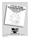
KIT # 1201810
Owner’s Installation Guide for the
Paxton Automotive
Novi 2000 Supercharger
for the
2003-2005 Dodge Viper
Paxton Automotive . 1300 Beacon Place . Oxnard CA 93033
805 604-1336 . FAX • 805 604-1337
DP/N: 4809644 - v2.0
12/13/04
FOREWORD
P
roper installation of this supercharger kit requires general
automotive mechanic knowledge and experience. Please
browse through each step of this instruction manual prior to
beginning the installation to determine if you should refer the job
to a professional installer/technician. Please call Paxton
Automotive for installers in your area.
© 2005 PAXTON AUTOMOTIVE
All rights reserved. No part of this publication may be reproduced, transmitted, transcribed,
or translated into another language in any form, by any means without written permission
of Paxton Automotive.
P/N: 4809644
©2005 Paxton Automotive
All Rights Reserved, Intl. Copr. Secured
13DEC04 v2.0 03-05Viper(4809644v2.0)
ii
TABLE OF CONTENTS
FOREWORD . . . . . . . . . . . . . . . . . . . . . . . . . . . . . . . . . . . . . . . . . . . . . . . . . . . . . . . . . . . . . . . . . ii
TABLE OF CONTENTS . . . . . . . . . . . . . . . . . . . . . . . . . . . . . . . . . . . . . . . . . . . . . . . . . . . . . . . . iii
IMPORTANT NOTES . . . . . . . . . . . . . . . . . . . . . . . . . . . . . . . . . . . . . . . . . . . . . . . . . . . . . . . . . . iv
RECOMMENDED TOOLS . . . . . . . . . . . . . . . . . . . . . . . . . . . . . . . . . . . . . . . . . . . . . . . . . . . . . . v
1.
PREPARATION/REMOVAL . . . . . . . . . . . . . . . . . . . . . . . . . . . . . . . . . . . . . . . . . . . . . . . 1-1
2.
OIL FEED. . . . . . . . . . . . . . . . . . . . . . . . . . . . . . . . . . . . . . . . . . . . . . . . . . . . . . . . . . . . . . 2-1
3.
OIL DRAIN . . . . . . . . . . . . . . . . . . . . . . . . . . . . . . . . . . . . . . . . . . . . . . . . . . . . . . . . . . . . 3-1
4.
CRANK PULLEY INSTALLATION . . . . . . . . . . . . . . . . . . . . . . . . . . . . . . . . . . . . . . . . . 4-1
5.
SUPERCHARGER MOUNTING BRACKET INSTALLATION. . . . . . . . . . . . . . . . . . . . . 5-1
6.
SUPERCHARGER INSTALLATION . . . . . . . . . . . . . . . . . . . . . . . . . . . . . . . . . . . . . . . . . 6-1
7.
TIMING CONTROLLER INSTALLATION . . . . . . . . . . . . . . . . . . . . . . . . . . . . . . . . . . . . 7-1
8.
CHARGE AIR COOLER INSTALLATION . . . . . . . . . . . . . . . . . . . . . . . . . . . . . . . . . . . . 8-1
9.
AUXILIARY FUEL PUMP ASSEMBLY INSTALLATION . . . . . . . . . . . . . . . . . . . . . . . . 9-1
10.
AIR INLET DUCT INSTALLATION . . . . . . . . . . . . . . . . . . . . . . . . . . . . . . . . . . . . . . . . 10-1
11.
FINAL CHECK . . . . . . . . . . . . . . . . . . . . . . . . . . . . . . . . . . . . . . . . . . . . . . . . . . . . . . . . . 11-1
iii
P/N: 4809644
©2005 Paxton Automotive
All Rights Reserved, Intl. Copr. Secured
13DEC04 v2.0 03-05Viper(4809644v2.0)
Dodge Viper
IMPORTANT NOTES
T
his product is protected by state common law, copyright and/or patent. All
legal rights therein are reserved. The design, layout, dimensions, geometry and engineering features shown in this product are the exclusive property of Paxton Automotive. This product may not be copied or duplicated in
whole or part, abstractly or fundamentally, intentionally or fortuitously, nor
shall any design, dimension, or other information be incorporated into any
product or apparatus without prior written consent of Paxton Automotive.
When driving the vehicle on non-public roads (off-road applications such as
racing/high rpm) it it recommended that the spark plugs be gapped down to
.032".
This supercharger kit is designed to work on stock vehicles. Vehicles with modifications may not be compatible with this kit as delivered and should be tested
with a wide band oxygen sensor and fuel pressure gauge to determine if the
air/fuel ratio is safe. Detonation will quickly damage an engine.
P/N: 4809644
©2005 Paxton Automotive
All Rights Reserved, Intl. Copr. Secured
13DEC04 v2.0 03-05Viper(4809644v2.0)
iv
Dodge Viper
B
efore beginning this installation, please
read through this entire instruction booklet and the Street Supercharger System
Owner's Manual which includes the Automotive
Limited Warranties Program and the Warranty
Registration form.
Paxton supercharger systems are performance
improving devices. In most cases, increases in
torque of 30-35% and horsepower of 35-45% can
be expected with the boost levels specified by
Paxton Automotive. This product is intended for
use on healthy, well maintained engines.
Installation on a worn-out or damaged engine is
not recommended and may result in failure of the
engine as well as the supercharger. Paxton
Automotive is not responsible for engine damage.
Installation on new vehicles will not harm or
adversely affect the break-in period so long as factory break-in procedures are followed.
For best performance and continued durability,
please take note of the following key points:
1. Use only premium grade fuel 91 octane or
higher (R+M/2).
2. The engine must have stock compression
ratio.
3. If the engine has been modified in any way,
check with Paxton prior to using this product.
4. Always listen for any sign of detonation
(pinging) and discontinue hard use (no boost)
until problem is resolved.
5. Perform an oil and filter change upon completion of this installation and prior to test
driving your vehicle. Thereafter, always use a
high grade SF rated engine oil or a high quality synthetic, and change the oil and filter
every 3,000 miles or less. Never attempt to
extend the oil change interval beyond
3,000 miles, regardless of oil manufacturer's claims as potential damage to the
supercharger may result.
6. Before beginning installation, replace all
spark plugs (follow the procedures indicated
within the factory repair manual and/or as
indicated on the factory underhood emissions
tag). Do not use platinum spark plugs
unless they are original equipment. Change
spark plugs at least every 15,000 miles and
spark plug wires at least every 50,000 miles.
RECOMMENDED TOOLS
FOR INSTALLATION:
1.
2.
3.
4.
5.
6.
7.
8.
9.
10.
11.
12.
13.
14.
15.
16.
17.
18.
19.
20.
21.
22.
Factory Repair Manual
3/8" Socket and Drive Set: SAE & Metric
1/2" Socket and Drive Set: SAE & Metric
3/8" NPT Tap and Handle
Adjustable Wrench
Combination Wrench: SAE and Metric
Center Punch
Springlock 3/8" and 5/16" Fuel Fitting
Disconnect Tool
10 Quarts SH/CF Rated Quality Engine Oil
Oil Filter and Wrench
Flat #2 Screwdriver
Phillips #2 Screwdriver
Heavy Grease
Silicone Sealer
Drill Motor / Pneumatic Right Angle
1/4" Drill Bits
Stepless Clamp Pliers
3/16" Allen Wrench
Wire Strippers and Crimpers
Utility Knife
Ø1-1/8" Hole Saw
Pliers
23. Threadlocker (Blue)
24. Thread Sealant
25. Fuel Pressure Gauge
If your vehicle has in excess of 10,000 miles
since its last spark plug change, then you will
also need:
26. Spark Plug Socket
27. NEW Spark Plugs
v
P/N: 4809644
©2005 Paxton Automotive
All Rights Reserved, Intl. Copr. Secured
13DEC04 v2.0 03-05Viper(4809644v2.0)
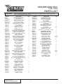
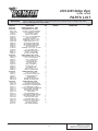
2003-2005 Dodge Viper
Part No. 1201840
PARTS LIST
IMPORTANT:
Before beginning installation, verify that all parts are included in the kit. Report any shortages or damaged parts immediately.
PART NO.
DESCRIPTION
QTY
1011840
2A038-495
4PCW038-375
VIPER SUPERCHARGER ASSY
BELT K080495
S/C PLY, 8-GRV 3.75" MOD
1
1
1
4PCW118-011
4PCCW016-011
4PCW018-011
4PCV110-010
7A312-100
7K312-001
7T100-120
7T110-125
7U250-023
CRANK PULLEY ASSY, VIPER
PULLEY, ACC, '03 VIPER
PULLEY, S/C CRANK, '03 VIPER
FIXTURE w/GUIDE, DWL PIN INST. V
5/16-18 x 1" HDCS GR5 P
5/16"AN WASHER
DRILL BIT, #31, Ø.120" HSS
REAMER, Ø.1247" HSS
DOWEL PIN, 1/8" x 1.25"
1
1
1
1
12
12
1
1
2
4PCW111-033
2A017-497
2A017-103-110
2A017-462
2A017-875-05
4PCW010-033
4PCW010-044
4PCW016-021
4PCW016-031
4PCW017-011
4PCW017-168
7A312-875
7A375-126
7A375-224
7A375-276
7A375-300
7A375-425
7A375-562
7A375-950
7F312-018
7F375-016
7J312-000
7J375-044
MTG PLATE ASSY, VIPER
SPACER, 4.975"L, '03 VIPER, MTG BRKT
SPACER, COG TENSIONER IDLER 35
SPACER, IDLER, SMOOTH 6-RIB
SPACER, .875"ID, .404"ID x 3.489" LONG
PLATE, MTG PRIMARY
PLATE, S/C MOUNTING
PULLEY, ALTERNATOR, '03 VIPER
IDLER PULLEY, 8-RIB GROOVED, MO
SPACER, BLOCK UPPER SRT10
SPACER, FACTORY IDLER SRT10
5/16-18 x 8.75" STUD GR8 ZNC
3/8-16 x 1.25" HXHD GR8 PLT
3/8-16 x 2.25" GR5 HX
3/8-16 x 2-3/4" HXHD ZINC
3/8-16 x 3" HXCS G5P
3/8-16 x 4-1/4"
3/8-16 x 5-5/8" ALL THREAD
3/8-16 x 9.5" ALL THREAD
5/16-18 NUT USS PLTD
3/8-16 HX NUT
5/16" FLAT WASHER, SAE
3/8" SAE WASHER, PLTD
1
1
4
1
1
1
1
1
1
1
1
1
7
1
1
1
1
1
1
1
4
1
19
4PCW111-052
4PCW010-100
4PCW010-110
4PCW011-052
4PCW016-171
7A375-275
7A375-602
7C008-050
7C010-067
7F375-016
7J010-002
SPRING TENS, ASSY, '03 VIPER 8-RIB
BLOCK, TENS. RECEIVER
BLOCK, TENS. THRUST
SPRING TENSIONER, WITH IDLER BO
IDLER PULLEY, 8-RIB SMOOTH, MOD
3/8-16 x 2-3/4" HXCS G8P
3/8-16 x 6 HHCS FLY THRD w/GROOVE
#8-32 x 1/2" SOC HD BOLT
M10-1.5 x 65 HXCS G8P FULLY THREADED
3/8-16 HEX NUT
10mm WASHER, PLATED
1
1
1
1
1
2
1
1
17
1
1
4PCW130-026
7P125-004
7P125-005
7P125-034
7U100-055
7U250-220
OIL FEED LINE ASSY. VIPER
1/8"NPT 90° x -4 JIC FTG
1/8"NPT x -4 JIC FTG
1/8"NPT x 1/8"NPT STRT T
TIE-WRAP, 6" NYLON
OIL FEED HOSE, 22" -4 STRT
1
2
1
1
2
1
4PCW130-036
7P375-055
7R001-008
7T560-001
7T560-002
7U030-036
7U100-066
OIL DRAIN LINE ASSY. VIPER
3/8"NPT 90° x 1/2" HOSE BARB
#8 STNLS HOSE CLAMP
CUTTER, 9/16" ROTABROACH
ARBOR, ROTABROACH
1/2" OIL DRAIN HOSE
TIE-WRAP, 11" NYLON
1
1
2
1
1
1.5'
2
P/N: 4809644
©2005 Paxton Automotive
All Rights Reserved, Intl. Copr. Secured
13DEC04 v2.0 03-05Viper(4809644v2.0)
PART NO.
4PCW112-010
4PCW012-010
4PCW012-020
7A250-104
7F250-040
7P375-113
7P500-001
7P500-003
7PS400-225
7R002-064
7U030-056
7U037-030
7U100-065
8H040-210
4809644
vi
DESCRIPTION
QTY
AIR INTAKE ASSY. '03 VIPER
INLET DUCT, '03 VIPER, SC
BRKT, AIR FILTER RETAINER
1/4-20 x 1" BHCS SS
1/4-20 NUT PLATE
PCV VALVE, VIPER, 3/8-1/2" HOSE 90
1/2" HOSE UNION
1/2"-3/8" REDUCER BARB UNION
BUMP SLEEVE, BLACK, 4D x 2.25"
#64 GOLDSEAL HOSE CLAMP
3/8" PCV HOSE
-8 USCG FUEL HOSE, PUSH-ON
GROMMET, .5"ID, .187" GRV
AIR FILTER, 7.5" x 23.75" PANEL, '03 VIPER
1
1
1
4
2
1
2
1
1
2
0.167'
2'
1
1
VIPER MANUAL, 2003-2004
1
5A001-076
5A001-070
5W001-017
7P156-119
7U375-001
7U375-002
TIMING CONTROL BOX, VIPER
TIMING CONTROL BOX, VIPER
3/8" RING TERMINAL, 12GA
5/32" UNION (Ø.156"OD)
VELCRO-HOOK, 1" BLACK
VELCRO-LATCH, 1" BLACK
1
1
1
1
0.22YD
0.22YD
4PCW101-003
SW001-005
5W001-011
5W014-030
7E010-075
7P375-072
7P375-006
7P312-017
7P312-082
7R004-001
7U031-018
7U100-044
7U100-055
8F001-068
7U375-001
7U375-002
FUEL PUMP ASSY. VIPER
3/8" PLASTIC WIRE LOOM
16-14GA RING TERM. .26" HOLE
14GA STRD WIRE, BLACK
#12 x 3/4" SHT METAL SCRW, HEX
3/8" FEMALE FUEL FTG. STEEL
3/8" GM FUEL TO 5/16" BARB FTG.
5/16" HOSE BARB TO PBURG OUT
5/16" TEE HOSE BARB
STEPLESS CLAMP, 15.7-70
5/16" FUEL HOSE, HI-PSR
TIE-WRAP, 4" NYLON
TIE-WRAP, 6" NYLON
INLINE FUEL PUMP
VELCRO-HOOK, 1" BLACK
VELCRO-LATCH, 1" BLACK
1
6'
2
1.5'
4
1
1
2
4
22
8
10
5
2
0.25YD
0.25YD
4PCV238-068
7P156-082
7U030-046
6Z050-191
6Z070-030
FMU ASSY, VIPER w/SPRING
5/32" TEE
5/32" VACUUM LINE
FMU WASHER, 8:1 PLATED
FMU, 8:1 RING SPACER
1
2
8'
1
1
2003-2005 Dodge Viper
Part No. 1201840
PARTS LIST
IMPORTANT:
PART NO.
8PN301-040
8PN201-040
8PN101-040
4PCW012-030
7J006-093
7P125-025
7P375-250
7P500-034
7PS300-200
7PS375-200
7PS450-200
7R002-048
7R002-060
7R002-072
7U030-046
7U100-065
7U133-060
8D204-010
8H040-175
8N055-050
8PN105-040
8PN010-170
7A250-051
7A250-075
7F250-021
7J250-001
7P375-075
7P500-026
7R007-001
7U038-000
7U038-012
8N055-030
8PN106-040
7A250-074
7F250-021
7J250-001
8N006-010
8PN010-150
8PN010-160
8PN107-020
5W001-005
5W001-009
5W001-010
5W001-011
5W001-013
5W001-014
5W001-015
5W001-016
5W001-017
5W001-040
5W014-010
5W014-030
5W014-030
5W016-010
7GL10-150
7U100-044
8F001-402
Before beginning installation, verify that all parts are included in the kit. Report any shortages or damaged parts immediately.
DESCRIPTION
POWER COOLER ASSY. ' VIPER
DISCHARGE ASSY. '03 VIPER
CAC ASSY, '03 VIPER, AIR/WATER
DUCT, DISCHARGE, '03 VIPER
6mm WASHER, PLATED
1/8"NPT x 5/32" HOSE 90
3/8" x 3/8" x 1/4" MALE BARB TEE
1/2"NPT 3/4" BARB 90°
SLEEVE, BLACK, Ø3.00" x 2.00"L
SLEEVE, BLACK, Ø3.75" x 2.00"L
SLEEVE, BLACK, Ø4.5" x 2.0"L
#48 GOLDSEAL HOSE CLAMP
#60 GOLDSEAL HOSE CLAMP
#72 GOLDSEAL HOSE CLAMP
5/32" VACUUM LINE
GROMMET, 5"ID, .812"OD, .187" GRV
3/4" x 90° HOSE, LONG
RACE BYPASS VALVE, BLACK
FILTER, 1-3/4"ID, MFRB
PLASTIC CAP, SURGE TANK
WATER TANK MTG ASSY, VIPER
SUPPORT,WATER TANK, '03 VIPER
1/4-20 x .50" HXHD ZN PLT
1/4-20 x .75" SHCD PLTD
1/4-20 NYLOCK NUT
1/4" SAE WASHER, PLTD
3/4" HOSE UNION
1/2"NPT, 3/4" BARB, 90°
NYLON CLAMP, 1-1/8"
3/4" HEATER HOSE
HOSE, Ø3/4" 90°, 4 x 12"
TANK, LT1 AFTERCOOLER
WATERCOOLER ASSY, VIPER
1/4-20 x 3/4" HXHD PLT
1/4-20 NYLOCK NUT ZINC PLTD
1/4" SAE WASHER, PLTD
WATERCOOLER
SUPPORT, DS VIPER, SRT10
SUPPORT, PS VIPER, SRT10
WATER PUMP ASSY, VIPER
3/8" PLASTIC WIRE LOOM
16-14GA MALE SLIDE INSULATED
16-14GA FEMALE SLIDE INSULATED
16-14GA EYELET .25" HOLE
14-16AWG, SOLDERLESS CONNECTOR
FUSE HOLDER, 10GA WIRE
FUSE, BLADE TYPE 20AMP
RELAY, BOSCH
3/8" RING TERMINAL 12GA
12-10GA FEMALE SLIDE INSULATED
14GA STRD WIRE RED, UL1015
14GA STRD WIRE, BLACK
14GA STRD WIRE, BLACK
WIRE, STRND, 16AWG, YELLOW
10mm x 1.5" NYLOCK NUT
TIE-WRAP, 4" NYLON
PUMP, WATER PIERBURG
QTY
PART NO.
DESCRIPTION
QTY
1
1
1
1
4
1
1
2
1
1
1
2
2
2
8'
1
1
1
1
1
1
1
2
1
1
4
2
6
12
6'
3
1
1
6
6
12
1
1
1
1
7'
1
3
2
2
1
1
1
1
1
7'
2'
7'
2'
1
8
1
vii
P/N: 4809644
©2005 Paxton Automotive
All Rights Reserved, Intl. Copr. Secured
13DEC04 v2.0 03-05Viper(4809644v2.0)
This Page Left Intentionally Blank.
P/N: 4809644
©2005 Paxton Automotive
All Rights Reserved, Intl. Copr. Secured
13DEC04 v2.0 03-05Viper(4809644v2.0)
viii
Section 1
COMPONENT REMOVAL
1.
PREPARATION/REMOVAL
A. Disconnect the Idle Air Control (IAC) motor
hose and the valve cover breather hose from
the air box (air filter housing).
B. Remove the air box and all of the inlet ducting up to but not including the throttle body.
C. Remove the air temperature sensor from the
air box and set aside.
D. Jack the front of the vehicle up and support
with a jack stand under each frame rail.
E. Remove the front lower splash pan from
underneath the vehicle (composite pan
underneath the steering rack).
F. Remove the nut securing the alternator pulley. Remove the accessory drive belt.
Remove the alternator pulley.
G. Remove the six 5/16" screws securing the
crank pulley to the harmonic damper and
remove the crank pulley (the harmonic
damper need not be removed).
1-1
P/N: 4809644
©2005 Paxton Automotive
All Rights Reserved, Intl. Copr. Secured
13DEC04 v2.0 03-05Viper(4809644v2.0)
This Page Left Intentionally Blank.
P/N: 4809644
©2005 Paxton Automotive
All Rights Reserved, Intl. Copr. Secured
13DEC04 v2.0 03-05Viper(4809644v2.0)
1-2
Section 2
OIL FEED
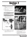
2. OIL FEED
A. Remove the oil dipstick by removing the
retaining screw from the passenger side
valve cover.
B. Drain the engine oil and remove the oil
filter.
C. Remove the oil pan.
D. Remove the oil pressure sender (1 1/8")
from the passenger side of the engine in
front of the engine mount.
*** IMPORTANT ***
Use clean engine oil on the pipe threads. Teflon tape
and sealant is NOT recommended as it might loosen
and cause blockage of the small oil feed orifice resulting in supercharger failure.
E.
F.
Fig. 2-b1 (2003 Viper)
Install the 1/8" NPT TEE in the oil sender
hole. Leave the TEE pointed down.
Install the appropriate 1/8" NPT x –4 fitting
into the TEE as shown in Fig. 2-a.
2003 VIPER OIL FEED
FITTING AND LOCATION
1/8"NPT TEE
2004-2005 VIPER OIL
FEED FITTING AND
LOCATION
Fig. 2-b2 (2004-2005 Viper )
Fig. 2-a
H. Temporarily cover one end of the oil feed
line and protect it from debris until connecting it to the supercharger.
I. Connect the open end of the oil feed line to
the -4 fitting. Use tie wraps to secure the line
and protect it from kinking, abrasion, and
high heat areas.
G. Install the oil pressure sender in the remaining hole in the TEE and re-attach electrical
plug (see Fig. 2-b1 or 2-b2).
2-1
P/N: 4809644
©2005 Paxton Automotive
All Rights Reserved, Intl. Copr. Secured
13DEC04 v2.0 03-05Viper(4809644v2.0)
This Page Left Intentionally Blank.
P/N: 4809644
©2005 Paxton Automotive
All Rights Reserved, Intl. Copr. Secured
13DEC04 v2.0 03-05Viper(4809644v2.0)
2-2
Section 3
OIL DRAIN
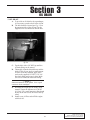
3. OIL DRAIN
A. To provide an oil drain for the supercharger,
it is necessary to make a hole in the oil pan.
B. The hole should be located per Fig. 3-a on
the passenger side of the oil pan. Use the
supplied 9/16" rota-broach to drill the hole.
Fig. 3-a
C. Tap the hole with a 3/8" NPT tap until the
oil drain fitting can be started.
D. Thoroughly clean the threaded area and the
inside of the oil pan. Apply a small amount
of sealer to the new threads. Apply more
sealer to the supplied 3/8" NPT x 1/2" 90º
hose barb fitting and secure in hole. Make
sure seal is formed all around the fitting.
*** NOTE ***
Clean and inspect the oil pan gasket. If it is in good
condition it can be used again.
E.
F.
Re-install the oil pan per the factory shop
manual. Torque the fasteners to 95 in-lbs
(11 N-m). Use a small amount ot blue thread
locker on the four screws in front of the flywheel.
Install a new oil filter and refill the engine
with fresh oil.
3-1
P/N: 4809644
©2005 Paxton Automotive
All Rights Reserved, Intl. Copr. Secured
13DEC04 v2.0 03-05Viper(4809644v2.0)
This Page Left Intentionally Blank.
P/N: 4809644
©2005 Paxton Automotive
All Rights Reserved, Intl. Copr. Secured
13DEC04 v2.0 03-05Viper(4809644v2.0)
3-2
Section 4
CRANK PULLEY INSTALLATION
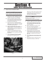
4.
CRANK PULLEY INSTALLATION
Make sure to make small cuts and cool with
cutting fluid to prevent the drill from overheating and breaking. Remove drill from
hole often to clean out chips.
*** NOTE ***
Dowel pins must be installed throught the damper and
into the crankshaft to assure that the damper does not
rotate in the crankshaft snout during engine operation.
A. Remove the two bolts securing the power
steering rack (15/16"). Make sure to note the
location of any shims for reinstallation.
B. Remove the harmonic damper retaining
screw. Placing the vehicle in first gear with
the emergency brake applied should keep
the engine from turning over.
C. Dowel pins must be installed through the
damper and into the crankshaft to assure that
the damper does not rotate on the crankshaft
snout during engine operation.
D. Install the supplied drill guide onto the
damper using two of the screws that held the
crankshaft pulley on. Orient the damper so
that the hardened drill insert is rotated to be
as high as possible.
E. Move the steering rack forward as far as
possible to provide drill clearance. Pushing
the rack to the driver side may provide additional room.
F. Using a right angle drill and the supplied
#31 (.120") drill bit, drill into the damper
face at least 1-1/4". (See Fig. 4-a)
*** NOTE ***
Remember to add 5/16" for the drill guide thickness.
The drill bit must go in at least
1-9/16" from the front surface of the drill guide.
G. Using the supplied 1/8" reamer, plunge once
to the end of the drilled hole and remove.
The chucking portion of the reamer shaft
may be shortened with side cutters to provide drill clearance.
H. Remove drill guide from damper. Clean
chips from in and around the hole.
I. Line up one of the supplied Ø1/8" x 1-1/4"
dowel pins and lightly tap the tapered end
into the reamed hole until flush.
J. Rotate drill guide 180° from previously
installed position so that it pilots on the
exposed dowel pin. Rotate engine until the
drill insert is at highest point and repeat
steps F-I.
K. Tap both dowel pins into the damper until
they are flush with or below the face of the
damper.
L. Re-install the damper retaining bolt using
threadlocker and torque to 250 ft-lbs.
Fig. 4-a
4-1
P/N: 4809644
©2005 Paxton Automotive
All Rights Reserved, Intl. Copr. Secured
13DEC04 v2.0 03-05Viper(4809644v2.0)
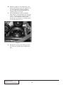
M. Install the supplied 7-rib crank pulley onto
the harmonic damper using the supplied 5/16
x 1" hex head bolts, washers and thread
locker. Torque the six mounting bolts in a
rotating pattern to 20 Ft-lbs.
N. From underneath the vehicle, install the
supercharger 8 rib crank pulley onto the pilot
on the 7 rib crank pulley. Install the supplied
5/16" x 1" hex head bolts, washers and
thread locker and torque in a rotating pattern
to 20 Ft-lbs. (See Fig 4-b.)
Fig. 4-b
O. Reinstall the steering rack making sure that
any shims are located in their original location.
P/N: 4809644
©2005 Paxton Automotive
All Rights Reserved, Intl. Copr. Secured
13DEC04 v2.0 03-05Viper(4809644v2.0)
4-2
Section 5
SUPERCHARGER MOUNTING BRACKET INSTALLATION
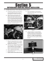
5..
SUPERCHARGER MOUNTING BRACKET INSTALLATION
A. Disconnect the emissions line from the bottom of the throttle body and re-route it on
top of the shock tower brace to provide
supercharger belt clearance. (See Fig. 5-b.)
B. Remove the factory metal idler from its
location underneath the throttle body.
Remove the retainer from the idler and flip
the idler front to back. Install the supplied
3/8 x 5-5/8" all thread into the idler mounting boss. Install the factory idler (inverted)
and factory retainer onto the stud and secure
with the supplied aluminum hex nut spacer
(See Fig. 5-a.) Leave the all-thread protruding about 2-5/8" past the spacer.
G. Route the supplied 8-rib belt around the
crank pulley and the upper alternator spacer
block (See Fig. 5-b.)
EMISSIONS LINE
UPPER ALTERNATOR SPACER
A/C STUD AND SPACER
/8
2-5
Fig. 5-b
H. Using the supplied 4-1/4" bolt installed
through two washers, install the supplied
8-rib idler with the fence (raised lip on one
edge) nearest the primary mounting plate.
(See Fig. 5-c.) Make sure that the pulley is
piloted on one side of the supplied spacer
and the other side of the spacer rests flat on
the plate.
Fig. 5-a
C. Remove the upper alternator bolt. Loosely
install the upper alternator spacer using the
supplied 3/8 x 3" bolt and washer through
the upper alternator mount.
D. Remove the A/C compressor bolt nearest the
water pump pulley. With the supplied 3-1/2"
spacer installed on it, insert the supplied
5/16 x 8-3/4" stud into the vacant hole.
Thread in as far as possible by hand or until
about 1" protrudes past the spacer.
E. Loosely install the supplied alternator pulley
using the factory nut.
F. Route the factory accessory drive belt in the
original manner but do not tension or install.
Fig. 5-c
5-1
P/N: 4809644
©2005 Paxton Automotive
All Rights Reserved, Intl. Copr. Secured
13DEC04 v2.0 03-05Viper(4809644v2.0)
Install the primary mounting plate onto the
previously installed studs making sure that
the 8 rib belt is routed around the 8 rib idler.
J. Install the supplied 5/16" nut and washer
onto the A/C stud.
K. Insert 3/8 x 1-1/4" bolts through the mounting plate and into the threaded holes in the
upper spacer block and tighten.
L. Tighten the alternator bolt securing the
upper alternator spacer block.
M. Remove the lower alternator bolt. Install the
supplied 3/8 x 10-1/4" all thread through the
lower alternator mounting location. Install a
supplied nut and a washer on the end of the
all thread behind the alternator. Slide the
lower alternator spacer onto the all thread.
N. Install the accessory drive belt in its original
configuration by retracting the factory
spring tensioner. (See Fig. 5-d.)
I.
Fig. 5-d
O. Tighten the alternator pulley nut.
P/N: 4809644
©2005 Paxton Automotive
All Rights Reserved, Intl. Copr. Secured
13DEC04 v2.0 03-05Viper(4809644v2.0)
5-2
Section 6
SUPERCHARGER INSTALLATION
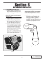
6.
SUPERCHARGER INSTALLATION
A. Install the supplied 1/2" oil drain hose on
the barb fitting on the bottom of the supercharger and secure with the supplied #8 hose
clamp.
*** NOTE ***
Do not use teflon tape or paste on the fittings as a
piece may break loose and clog an orifice resulting in
supercharger failure.
E.
Install the supplied 90º fitting into the supercharger oil feed so that it will point downward when the supercharger is installed.
C. Attach the supercharger mounting plate to
the supercharger. Use the supplied 3/8" x 11/4" bolts and washers. Leave one of the
mounting holes empty. (See Fig. 6-a.)
D. Install the spring tensioner onto the supercharger mounting plate using the supplied
3/8 x 2-3/4" screw and washer. The tensioner locating pin should be in the counterclockwise-most hole in the mounting plate
as viewed in Fig. 6-a. Use the supplied
spring tensioner release tool to fully retract
the spring tensioner. (See Fig. 6-a.)
B.
(Use a 3/8" x 1" bolt through the mounting
plate to hold the thrust block. The receiver
block seats on the protruding threads of the
spring tensioner idler retaining bolt.)
SPRING TENSIONER RETRACT TOOL
*** NOTE ***
Bending the factory hard line that runs to the radiator
fan will provide supercharger clearance. Test fit and
then bend as necessary in the middle of the line (avoid
stressing the ends
With 1.1" spacers at all connection points
between the two plates, attach the supercharger plate assembly to the primary
mounting plate using the supplied 3/8" hardware. Route the oil drain hose over the
steering rack. Make sure that the back of the
supercharger drive belt encircles the spring
tensioner idler. (See Fig. 6-b.)
SUPERCHARGER
PULLEY
RIBBED
IDLER
SMOOTH
SPRING
TENSIONER
IDLER
NO BOLT IN HOLE
CRANK SHAFT
PULLEY
THRUST BLOCK
Fig. 6-b
Fig. 6-a
6-1
P/N: 4809644
©2005 Paxton Automotive
All Rights Reserved, Intl. Copr. Secured
13DEC04 v2.0 03-05Viper(4809644v2.0)
F.
Install the 3/8 x 2-3/4" bolt through the
mounting plate assembly and into the open
hole in the supercharger gear case. Install
the 3/8 x 2-1/4" bolt in the open hole at the
bottom of the supercharger plate and thread
into the primary plate. (See Fig. 6-c.)
K. Route the free end of the oil feed hose to the
supercharger oil feed fitting
*** NOTE ***
Make sure there are no bends, kinks or dips in the oil
drain line. The hose must maintain a constant "downhill" routing. Restriction in the drain path may cause
seal leakage and/or supercharger failure
2-3/4" BOLT
Attach the free end of the oil drain hose to
the previously installed oil drain fitting in
the oil pan and secure with a #8 hose clamp
(cut hose for best fit).
M. Use zip-ties as necessary to secure the oil
drain and oil feed lines away from moving
parts.
L.
2-1/4" BOLT
Fig. 6-c
G. Install the 5/16" nut and washer on the A/C
stud and a 3/8" nut and washer on the lower
alternator stud.
*** NOTE ***
The front of the lower alternator stud is difficult to
reach. Try to start and thread on front nut by hand.
Final wrench tightening can be done on the rear nut
which is accessable.
H. Install the supercharger belt onto the supercharger pulley. Make sure that the 8-rib
grooved idler is seated square on the spacer
pilot and install a nut and washer on its
retaining bolt.
*** NOTE ***
In order to provide belt clearance to the shock tower
brace, the supercharger pulley may interfere with the
alternator pulley. Carefully check the following:
I.
J.
Check the supercharger pulley nose to alternator belt clearance. If necessary, lift the
supercharger assembly while tightening the
mounting plate fasteners. Tighten all of the
mounting plate assembly fasteners. Verify
that the nose of the supercharger pulley
is not touching the accessory drive belt.
Loosen and then remove the previously
installed spring tensioner retract tool from
the supercharger mounting plate.
P/N: 4809644
©2005 Paxton Automotive
All Rights Reserved, Intl. Copr. Secured
13DEC04 v2.0 03-05Viper(4809644v2.0)
6-2
Section 7
TIMING CONTROLLER INSTALLATION
7. TIMING CONTROLLER INSTALLATION
E.
*** NOTE ***
The VIOLET (and green and yellow if equipped) wire is
not used. Tape up to avoid confusion.
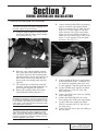
A. Using the supplied adhesive backed Velcro,
position the ignition timing control computer as shown. (See Fig. 7-a.)
Connect the thin 20GA RED wire to battery
positive switched by the ignition (Black
PCM C1 connector, Pin # 2, Pink with gray
stripe wire). Use the supplied T-Tap and
spade connector. The yellow water pump
trigger wire (to be installed in Section 8-c)
should also be connected to the same power
source. Use the supplied T-Tap and spade
connector. (See Fig. 7-b.)
Fig. 7-a
Route the wires and the supplied vacuum
hose (using hose union) back from the timing control, under the dash and through the
grommet located in the forward-upper driver
side footwell. Secure away from moving
objects such as the throttle pedal and steering shaft.
C. The vacuum hose on the timing controller
should be connected to intake manifold vacuum using the supplied TEE and hose.
D. Remove the rearmost (black) Powertrain
Control Module (PCM) connector C1.
B.
*** NOTE ***
Soldered wire connections are more sound than crimp
on connectors because they can be inspected. It is up
to the installer to guarantee good connections. If there
is any doubt, or the vehicle performs erratically, solder
and insulate each connection.
*** NOTE ***
The following steps have some information in parenthesis. This information applies to 2003 Vipers only.
Other vehicles are similar, but a factory service manual
should be consulted for verification. Always verify pin
location regardless of wire color!
7-1
Fig. 7-b
Connect the BLACK wire to signal ground
at the PCM (Black PCM C1 connector, Pin
# 4, Dark blue with dark green stripe wire).
Use the supplied T-Tap and spade connector.
G. Cut the CRANK sensor signal wire (Black
PCM connector C1, Pin # 8, Gray with
black stripe wire).
H. Connect the GRAY wire to the wire leading
to the crank sensor.
I. Connect the GRAY/BLACK wire to the
wire leading to the PCM crank sensor input.
J. Cut the CAM sensor signal wire (Black
PCM C1 connector, Pin # 18, Tan with yellow stripe wire).
K. Connect the TAN wire to the wire leading to
the cam sensor.
F.
P/N: 4809644
©2005 Paxton Automotive
All Rights Reserved, Intl. Copr. Secured
13DEC04 v2.0 03-05Viper(4809644v2.0)
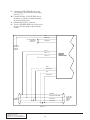
Connect the TAN/YELLOW wire to the
wire leading to the PCM cam sensor input.
(See Fig. 7-c.)
M. Connect the large 12 GAGE RED wire to
the battery (+) positive terminal located at
the front of the fuse box.
N. Reinstall the PCM C1 connector.
O. The two STRIPED RED wires will be used
to power the fuel pumps in the following
section.
L.
RED
RED/BLACK
WILL BE CONNECTED
IN SECTION 9
(SEE FIG. 9-C.)
RED/GREEN
TO POWER
TERMINAL AT
FRONT OF
FUSE BOX
RED - 20
BLACK - 20
VIOLET - 20
SUPPLIED
IGNITION
CONTROL BOX
GRAY
GRAY/BLACK
TAN
TAN/YELLOW
PINK/GRAY
DARK BLUE/DARK GREEN
TO
ENGINE/
SENSORS
GRAY/BLACK
TAN/YELLOW
Fig. 7-c
P/N: 4809644
©2005 Paxton Automotive
All Rights Reserved, Intl. Copr. Secured
13DEC04 v2.0 03-05Viper(4809644v2.0)
7-2
TO FACTORY
POWERTRAIN
CONTROL
MODULE
(PCM)
Section 8
CHARGE AIR COOLER INSTALLATION
8.
CHARGE AIR COOLER INSTALLATION
A. CHARGE AIR COOLER (CAC) CORE
INSTALLATION
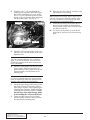
1. Using sealant, install 1/2" NPT to 3/4"
barb 90° fittings into the cooler end
tank so that they point towards the front
of the vehicle.
2. Install the supplied bypass valve onto
the cooler so that it points to the passenger side. If the bolts are too long
and no not tighten on the bypass valve
body, use the supplied additional washers under the bolt heads. Connect the
supplied 5/32" hose to the fitting on the
bypass valve.
3. Install the supplied air filter onto the
bypass valve and tighten the clamp.
4. Install a 3" sleeve on the cooler inlet
and a 3-3/4" sleeve on the outlet.
5. Install the CAC core assembly onto the
supercharger discharge and the throttle
body.
6. Install the supplied 4-1/2" sleeve onto
the throttle body. Secure with a hose
clamp.
7. Install the factory air temperature sensor into the hole in the driver’s side of
the discharge duct using one of the supplied grommets.
8. Install the discharge duct onto the CAC
outlet by rotating the assembly forward
and then connecting to the throttle
body. (See Fig. 8-a)
10. Install the supplied 90º hose (trimmed
as necessary) onto the 3/4" barb on the
passenger side of the discharge duct.
Secure with the factory clamps.
11. Plug in the air temperature sensor.
12. Route the vacuum line connected to the
bypass valve to the brake booster. Cut
the brake booster and install the supplied TEE. Connect the vacuum line to
the TEE.
B. RESERVOIR INSTALL
1. Remove the passenger’s side front
wheel from the vehicle.
2. Remove the inspection panel and the
horn brackets (located behind the passenger’s side fog light).
3. Install the supplied water tank bracket
into the original horn bracket mounting
location using the factory fasteners.
(See Fig. 8-b.)
Fig. 8-b
4.
5.
6.
Fig. 8-a
9.
7.
Verify that the charge air cooler and
bypass valve have sufficient clearance
and tighten the supplied clamps on all
of the sleeve connections.
8-1
The water tank should have 90° fittings
installed in the top and bottom.
Route an uncut piece of straight hose
from the engine compartment and connect it to the top of the water tank.
Install the water tank onto the bracket
using the lowest, most widely spaced
holes and two of the supplied 1/4"
screws and washers.
Connect the short leg of one of the supplied 90° hoses to the lower fitting on
the CAC core.
P/N: 4809644
©2005 Paxton Automotive
All Rights Reserved, Intl. Copr. Secured
13DEC04 v2.0 03-05Viper(4809644v2.0)
8.
9.
Using one of the supplied hose
menders, connect the long leg to the
hose attached to the top of the water
tank (trim as necessary).
Horn “A”
a. Using the factory 90° horn bracket
with the 2.75" short leg as a template, mark and drill a 5/32" pilot
hole approximately 5.5" forward of
the front sway-bar bracket bolt into
the frame rail. (See Fig. 8-c.)
Fig. 8-d
e. Verify that neither of the horn bodies are touching other components.
f. Reattach the electrical plugs to the
horns and verify undistorted horn
tone.
g. Reinstall the plastic inspection
panel and the front wheel.
C. CAC WATER PUMP WIRING AND
INSTALLATION
1. Cut a piece of the supplied hose to connect the bottom of the reservoir to the
inlet of the water pump.
2. The pump outlet should point up and
toward the front of the vehicle. (See
Fig. 8-e.)
Fig. 8-c
b. Mount the factory horn and bracket
to the frame using the supplied
sheet metal screw.
10. Horn “B”
a. Use the remaining factory horn
bracket (With 1" short leg) as a
template.
b. Mark and drill two 1/4" holes
approximately .5" from each other
on the inner fender. (See Fig. 8-d.)
c. Remove the horn from the bracket
and reattach it to the inside of the
factory 90° bracket.
d. Secure the horn and bracket to the
inner fender using the supplied 1/420 x 3/4" hex head bolt, washers
and nylock nut. (See Fig. 8-d.)
WATER PUMP
Fig. 8-e
P/N: 4809644
©2005 Paxton Automotive
All Rights Reserved, Intl. Copr. Secured
13DEC04 v2.0 03-05Viper(4809644v2.0)
8-2
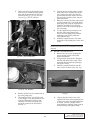
3.
6.
Drill a hole and use the supplied sheet
metal screw to mount the water pump
relay and the ground wire in the location shown in Fig. 8-f1 ('03-'04 vehicles) or Fig. 8-f2 ('05 vehicles).
7.
8.
9.
Connect the fuse holder using a yellow
slide connector to terminal #30 on the
CAC pump relay and to the fuse box
power terminal on the front of the fuse
box using the supplied yellow ring terminal connector.
Route the red wire from the water pump
to relay terminal #87. Cut off the water
pump plug and, using the supplied butt
connector, attach the red wire to the
positive wire on the water pump (green
wire on pump).
Use the supplied ring terminal to connect the water pump ground wire
(brown wire on pump) to the radiator
mounting screw directly under the
lower radiator hose.
Install the supplied plastic wire loom
around the water pump power wires and
secure
*** NOTE ***
Double check that all wires are connected to the proper
relay lugs
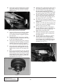
D. WATER COOLER INSTALL
1. Remove the two screws securing the
power steering cooler to the hood
release mechanism.
2. Using sealant, insert the 90° fittings in
the inlet and outlet of the water cooler
and point them towards the passenger
side of the vehicle.
3. Install the supplied brackets onto the
water cooler as shown. (See Fig. 8-g.)
Fig. 8-f1 ('03-'04 vehicles)
Fig. 8-f2 ('05 vehicles)
4.
5.
Run the ground wire to terminal #86 on
the water pump relay.
The supplied yellow wire will be used
as the “trigger” wire and should be connected to terminal #85 using a slide
connector. The other end of the wire
should be connected as described in
Section 7-e.
8-3
Fig. 8-g
4.
Connect the short end of one of the
supplied 90º hoses to the passenger side
of the water cooler and install and tighten clamp. Connect a length of hose
long enough to reach the water pump to
the other fitting and tighten clamp.
P/N: 4809644
©2005 Paxton Automotive
All Rights Reserved, Intl. Copr. Secured
13DEC04 v2.0 03-05Viper(4809644v2.0)
5.
6.
7.
8.
Drill the radiator air inlet duct using a 1
1/8" hole saw so that the hose can be
routed smoothly from the water cooler
to the water pump outlet.
Install the water cooler assembly
between the power steering cooler and
the hood latch mechanism.
Bolt the power steering cooler to the
brackets at the lowest location using the
supplied hardware.
Bolt the brackets to the hood latch
mechanism using the factory hardware.
(See Fig. 8-h.)
10. Route 90º 3/4" hose between the radiator and the passenger side frame rail.
Install a 90º hose on the top fitting on
the CAC core with the short leg
trimmed as short as possible. Connect
the two hoses using a supplied hose
mender. (See Fig. 8-i.)
Fig. 8-i
11. Verify that clamps have been installed
and tightened on each hose connection
and that all hoses are routed as smoothly as possible.
12. Remove the cap and fill the system
with 25%/75% coolant/water mix. Fill
system slowly and completely.
Fig. 8-h
9.
Connect the outlet of the water pump to
the far side of the water cooler with the
installed 3/4" hose trimmed to fit.
FLOW
FLOW
Fig. 8-j
P/N: 4809644
©2005 Paxton Automotive
All Rights Reserved, Intl. Copr. Secured
13DEC04 v2.0 03-05Viper(4809644v2.0)
8-4
Section 9
AUXILIARY FUEL PUMP ASSEMBLY INSTALLATION
9.
AUXILIARY FUEL PUMP ASSEMBLY INSTALLATION
A. Plumb the supplied fuel pumps in parallel by
connecting the pump inlets to a TEE fitting.
Do the same with the outlets. The pumps are
INSTALL AND TIGHTEN
CLAMP USING STEPLESS
CLAMP PLIERS (20 PLACES)
ROUTE TO GROUND LOCATION
UNDERNEATH THE WINDSHIELD
SUPPLIED FUEL PUMP FITTINGS
(4-PLACES) (VERIFY THAT THE
COPPER WASHER IS INSTALLED
AND FITTING IS TIGHT)
SUPPLIED FEMALE
SPRING LOCK
CONNECTOR
VEHICLE
SUPPLY
LINE FROM
FUEL TANK
VEHICLE
FUEL
RAIL
now configured so that one TEE feeds both
pump inlets and another TEE draws from
both pump outlets. (See Fig. 9-a.)
SUPPLIED
FUEL PUMPS
5/32" HOSE BARB TEE
(4 PLACES)
ROUTE TO TEE
IN BYPASS
VALVE VACUUM
LINE
5/32" HOSE (CONNECTED
TO MANIFOLD PRESSURE)
CUT SUPPLIED EFI FUEL HOSE
TO LENGTH (10 PLACES)
SUPPLIED
FEMALE
SPRING LOCK
CONNECTOR
MARK AND DRILL TWO HOLES - INSTALL
THE SUPPLIED SHEET METAL SCREWS
TO HOLD THE FUEL CONTROL UNIT
FCU COVER
SPRING
SPRING RETAINERS
LARGE DIAPHRAM
8:1 WASHER
(Ø2.22")
8:1 RING SPACER
FCU (SUGGESTED
INITIAL CALIBRATION
FOR MODIFIED VEHICLES
AND 2005 VEHICLES)
FCU COVER
SPRING
SPRING RETAINERS
LARGE DIAPHRAM
6:1 WASHER (Ø1.855")
6:1 RING SPACER
FCU (AS SUPPLIED IN KIT
2003-2004 VEHICLES)
Fig. 9-a
9-1
P/N: 4809644
©2005 Paxton Automotive
All Rights Reserved, Intl. Copr. Secured
13DEC04 v2.0 03-05Viper(4809644v2.0)
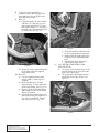
B.
H. Install the FCU in the location shown in Fig.
9-d using the supplied sheet metal screws.
I. Cut the auxiliary fuel pump supply (inlet)
line and install a supplied TEE inline.
Connect the fuel line coming out of the bottom center (outlet) of the FCU to this TEE.
J. Cut the auxiliary fuel pump discharge (outlet) line and install another supplied TEE
inline. Connect the fuel line coming out of
side (inlet) of the FCU to this TEE.
K. All of the hose connections should have
clamps installed and tightened using stepless
clamp pliers.
L. Install a 3/16" TEE into the air bypass valve
vacuum line. Attach the supplied 5/32" line
from the FCU cover to the TEE.
M. Use the supplied Velcro on each pump to
insulate it from the vehicle. Install the supplied plastic wire loom around the fuel
pump power wires and secure.
N. Make sure that all fuel lines are routed as
smoothly as possible while avoiding heat
and sharp objects.
O. On 2005 model year vehicles, or vehicles
with any engine related modifications,
remove the six screws securing the FCU
cover. Replace the 6:1 calibration ring and
washer with the supplied 8:1 parts and reassemble. (See Fig. 9-a.)
Connect the ground terminals to the grounding location under the windshield using the
supplied wire and ring terminal connectors.
(See Fig. 9-b.)
Fig. 9-b / (As seen from the front of the
vehicle looking under the windshield)
C. Connect a striped red wire from the ignition
control box to each of the fuel pump positive terminals using the supplied ring terminal connectors.
D. Compress the plastic ring (or use a spring
lock disconnect tool) to disconnect the factory fuel line behind the engine.
E. Connect the supplied spring lock connector
to the factory fuel line running to the intake
manifold. Attach and route the supplied
5/16" fuel line to the fuel pump outlet TEE.
F. Connect the other supplied spring lock fitting to the factory fuel supply line with the
supplied hose routed to the fuel pump inlet
TEE.
G. Remove the metal bracket from the supplied
Fuel Control Unit (FCU) and re-install it so
that the fitting on the side of the FCU points
toward the back of the vehicle. Tighten the
bottom fitting until it points away from the
metal bracket. (See Fig. 9-c.)
Fig. 9-d
Fig. 9-c
P/N: 4809644
©2005 Paxton Automotive
All Rights Reserved, Intl. Copr. Secured
13DEC04 v2.0 03-05Viper(4809644v2.0)
9-2
Section 10
AIR INLET DUCT INSTALLATION
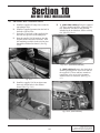
10.
AIR INLET DUCT INSTALLATION
A. Install the supplied 4" bump sleeve onto the
supercharger inlet.
B. Install the supplied grommet into the hole in
the back of the air inlet.
C. Insert the 4" hose barb of the supplied inlet
duct into the open end of the bump hose.
D. Start the supplied 1/4-20 hardware into the
original air box hold down locations. Drill
the remaining two holes in the air inlet duct
through the radiator fan shroud. (See Fig.
10-a.)
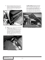
F.
1. (2003-2004 vehicles) Using the supplied
5/8" hose menders and hose, connect the factory crankcase vent hose to the grommet
installed in the air inlet duct. Secure with zip
ties. (See Fig. 10-c1.)
Fig. 10-c1 (2003-2004 vehicles)
2. (2005 vehicles) Remove the plastic hose
from the passenger side valve cover and use
the supplied 1/2" hose and hose mender to
connect the valve cover to the grommet
installed in the air inlet duct. (See Fig. 10c2.)
Fig. 10-a
E.
Install the supplied 1/4-20 nut plates onto
the newly drilled holes in the radiator
shroud. (See Fig. 10-b.)
Fig. 10-c2 (2005 vehicles)
Fig. 10-b
10-1
P/N: 4809644
©2005 Paxton Automotive
All Rights Reserved, Intl. Copr. Secured
13DEC04 v2.0 03-05Viper(4809644v2.0)
2. (2005 vehicles) Disconnect the rubber
elbow from the front of the driver’s side
valve cover. Install a short length of 3/8"
hose onto the inlet of the supplied PCV
valve. Install the rubber elbow over the 3/8"
hose and attach the other end of the PCV
valve to the valve cover using a short piece
of the supplied 1/2" hose. (See Fig. 10-e2.)
G. Slide the supplied air filter into the air box
and use the supplied retainer to hold it in.
Install the four fasteners through the retainer
and air inlet and into the radiator shroud.
(See Fig. 10-d.)
Fig. 10-d
H. Tighten the hose clamps on the supercharger
inlet.
I. 1. (2003-2004 vehicles) Remove the 1/2"
hose from the plastic TEE that connects the
intake manifold plenum to the rear of the
passenger side valve cover. Install the supplied PCV valve as shown in Fig. 10-e1
using the supplied 3/8" and 1/2" hose and
1/2" - 3/8" barb reducer.
Fig. 10-e2 (2005 Models)
Fig. 10-e1 (2003-2004 Models)
P/N: 4809644
©2005 Paxton Automotive
All Rights Reserved, Intl. Copr. Secured
13DEC04 v2.0 03-05Viper(4809644v2.0)
10-2
Section 11
FINAL CHECK
11.
FINAL CHECK
A. Reconnect battery.
B. Make sure that all oil feed and oil drain fittings are connected and tight and that the
engine is filled with factory specified oil.
C. Temporarily install a fuel pressure gauge
onto the –6 fitting on the fuel rail.
D. Cycle the fuel pump several times by turning
ignition on and then off. Check all fuel system hose connections for leakage.
E. With key on, make sure cooler water pump
is operating and that water is flowing
through the CAC. Fill as required. Toggle
the water pump several times to get as much
air out of the system as possible. Do not run
the water pump for extended periods (30
seconds or more) without water flow. Fill
frequently until the level stabilizes.
F. Engine detonation manifests itself as a
metallic rattling sound emanating from the
engine, usually at full throttle. It can quickly
destroy an engine. If detonation is detected,
discontinue hard use until the problem is
fixed.
G. Monitor the fuel pressure at full throttle. The
fuel pressure should reach about 100 psi at
5500 rpm. If this fuel pressure is not
achieved, increase the FCU calibration (e.g.
replace 6:1 ring and spacer with 8:1.) (See
Fig. 9-a.)
H. Read the “Street supercharger system
owner’s manual and return the warranty registration form” within thirty (30) days of
purchasing your supercharger system.
*** WARNING ***
If vehicle is to be driven in heavy rain, install a deflector
behind the hood scoop to prevent excessive water flow
from being introduced into the air box.
Fig. 11-a
11-1
P/N: 4809644
©2005 Paxton Automotive
All Rights Reserved, Intl. Copr. Secured
13DEC04 v2.0 03-05Viper(4809644v2.0)
1300 Beacon Place • Oxnard, CA 93033-9901 • (805) 604-1336
FAX (805) 604-1337 • paxtonautomotive.com • M-F 8:00 AM - 4:30 PM PST
P/N: 4809644
©2005 Paxton Automotive
All Rights Reserved, Intl. Copr. Secured
13DEC04 v2.0 03-05Viper(4809644v2.0)
11-2