1
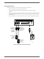
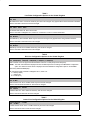
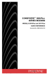
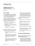
You have accessed an older version of a
Paradyne product document.
Paradyne is no longer a subsidiary of
AT&T. Any reference to AT&T Paradyne is
amended to read Paradyne Corporation.
Paradyne
COMSPHERE 3800Plus Modems
U.K. Supplement
Document Number 3980-A2-GK40-10
June 1995
Overview
This document highlights government requirements, safety warnings, installation procedures, features, and
functions that are unique to COMSPHEREr 3800Plus modems installed within the United Kingdom. This
document is intended to be used in conjunction with the COMSPHERE 3800Plus Modems User’s Guide,
Document No. 3980-A2-GB30. Please consult the User’s Guide for overall operation of the 3800Plus modem.
Regulatory Information
Ringer Equivalence Number
The Ringer Equivalence Number (REN) is a customer guide indicating approximately the maximum number of
items of apparatus that should be connected simultaneously to the telephone line. The sum of the RENs should
not exceed four. This value includes any BT-provided instrument which may be assumed to have a REN of 1
unless marked otherwise. The REN of this modem is 1.
Connection to Leased Lines
If any other apparatus, including cable or wiring, is connected between the apparatus and the point of connection
to any speechband circuit, then all that other apparatus shall comply with the following:
1. The overall transmission characteristics of all that other apparatus shall be such as to introduce no material
effect upon the electrical conditions presented to one another by the apparatus and the speechband circuit;
and
2. All that other apparatus shall comprise only:
(i) apparatus approved for the purpose of connection between the apparatus and a speechband circuit; and
(ii) cable or wiring complying with a code of practice for the installation of equipment covered by this
part of BS 6328 or such other requirements as may be applicable.
This modem is suitable for connection to BT circuits with signalling at a nominal frequency of 2280 Hz and may
be connected to multipoint or point to point circuits. The apparatus does not require signalling or otherwise use
the frequency range 0 –200 Hz.
No d.c. interaction is intended between the modem and the telephone network.
This apparatus may be directly connected to a speechband circuit or connected to a relevant branch system for
speechband circuits.
1
Connection to Supply Mains
IMPORTANT: The wires in the mains lead supplied with this equipment are coloured in accordance with the
following code:
Blue — Neutral
Brown — Live
As the colours of the cores in the mains lead of this equipment may not correspond with the coloured markings
identifying the terminals in your plug, proceed as follows:
• The core which is coloured blue must be connected to the terminal which is marked with the colour N or
coloured black.
• The core which is coloured brown must be connected to the terminal which is marked with the letter L or
coloured red.
Safety Notice
For pluggable equipment, the mains socket outlet shall be installed near the equipment and be easily accessible.
Interconnection circuits between this modem and any other equipment should be such that the equipment
continues to comply with the requirements of EN41003 for TNV (Telephone Network Voltage) circuits and
EN60950 for SELV (Safety Extra Low Voltage) circuits after making connection between circuits.
The power supply must be properly connected and switched on before the modem will work correctly.
Technical Specifications
Table 1 shows technical specifications that are unique to 3800Plus modems installed in the United Kingdom.
Table 1
Technical Specifications for the United Kingdom
Description
Specifications
TRANSMIT LEVEL
Leased Line
–13 dBm (factory default setting)
Dial Line
–9 dBm (factory default setting)
These settings can only be changed by qualified AT&T Paradyne
service personnel.
TELEPHONE INTERFACE
Leased-Line Connectivity
8-position modular jack (3810Plus requires VF cord with BT631A-type
modular plug)
50-pin mass termination (3811Plus)
Dial-Line Connectivity
8-position modular jack (3810Plus requires VF cord with BT431A-type
modular plug)
50-pin mass termination (3811Plus)
2
Equipment List
Table 2 shows a list of modems and telephone cords available for use in the United Kingdom.
Table 2
Equipment List for the United Kingdom
Equipment
Model/Part Number
3810Plus 4-wire/2-wire standalone
3811Plus 4-wire/2-wire carrier card
8-position, 4-wire to BT631A modular cord (leased line)
8-position, 2-wire to BT431A modular cord (dial line)
6-position, 4-wire modular cord, 7-foot length
8-position, 8-wire modular cord, 14-foot length
8-position to 6-position crossover modular cord
3980-A2-303
3981-B1-004
035-0170-0031
035-0169-0031
125-0067-0031
125-0053-1431
125-0054-1531
3810Plus Input Voltage Requirements
The power supply used with the 3810Plus modem (Figure 1) is designed for an input voltage of 240 Vac
(± 10 percent), and an input frequency of 50 Hz.
3810Plus Modem Installation
The following procedures describe how to connect the standalone modem to the leased line, dial line, and power
supply.
Before installing your modem, make sure your installation site is clean and well-ventilated. Allow space around
the modem for installing cables and telephone cords, and make sure the modem is located within reach of the
ac power outlet. The distance between your modem and DTE should be minimized if DTE data rates exceed
19,200 bps. Also, low capacitance cables may be necessary for speeds greater than 19,200 bps or distances greater
than 50 feet.
Figure 1 shows how 3810Plus modems are connected to certain TELCO jack types using the supplied cables.
3810Plus 4-wire/2-wire Leased-Line Connection
Use the following procedure to connect a 3810Plus to the leased-line network interface (use the VF cord labeled
LEASED LINE):
1. Insert the 8-position, 4-conductor modular plug into the jack labeled LEASED (3810Plus), Figure 1.
2. Insert the BT631A-type modular plug into the leased-line network interface.
3810Plus Dial-Line Connection
Use the following procedure to connect the modem to the dial network interface (use the VF cord labeled
DIAL LINE):
1. Insert the 8-position, 2-conductor modular plug into the jack labeled DIAL, Figure 1.
2. Insert the BT431A-type modular plug into the dial network interface.
3
Power Supply Connection
Use the following procedure to connect the standalone modem to an ac power outlet:
1. Make sure the modem’s power switch is in the OFF position.
2. Insert the power supply’s cylindrical connector into the modem’s rear panel power receptacle
(Figure 1).
3. Insert the transformer into the appropriate grounded ac outlet in accordance with requirements as stated in
EN60950: ‘‘For pluggable equipment, the socket outlet shall be installed near the equipment and shall be
easily accessible.”
4. Refer to the Modem Power-Up section in Document No. 3980-A2-GB30 for modem start-up procedures.
DIAL
LEASED LEASED
(3810Plus) (3820Plus)
8-POSITION,
4-CONDUCTOR
KEYED PLUG
FOR
LEASED-LINE
NETWORK
OPERATION
DTE
NMS
PWR
ON
OFF
8-POSITION,
2-CONDUCTOR
KEYED PLUG FOR
DIAL NETWORK
OPERATION
BT631A-TYPE
PLUG FOR
LEASED
NETWORK
INTERFACE
BT431A-TYPE
PLUG FOR DIAL
NETWORK
INTERFACE
POWER
SUPPLY
Figure 1. 3810Plus Rear Panel and Power Supply
4
495-14711
3811Plus Modem Installation
To install the 3811Plus modem (carrier card) into the COMSPHERE 3000 Series Carrier, follow the same
installation procedures described in the 3811Plus Modem Installation section of Document No. 3980-A2-GB30.
For correct power, DTE, dial, and leased-line cabling procedures, refer to the COMSPHERE 3000 Series Carrier,
Installation Manual, Document No. 3000-A2-GA31.
Note that the 3811Plus modem supports the following features:
• Carrier assembly
— 3000-B1-301 – COMSPHERE 3000 Series Carrier with 230 volt power transformer unit
— 3000-B1-701 – COMSPHERE 3000 Series Carrier with 200 volt power transformer unit (Hong Kong)
• Network Interface Modules (NIMs)
— 3000-F1-003 – RJ21X NIM without the Make Busy and Service Line feature
Configuration Options
This section lists functions and configuration options that are unique to the operation of 3800Plus modems
installed in the United Kingdom. The information described in this section differs from what is listed in
Document No. 3980-A2-GB30.
Please note that if a function or configuration option is not listed in this supplement, then your modem’s
functionality and operation follow what is described in Document No. 3980-A2-GB30.
Control Branch — Make Busy/Remove Make Busy Function
The Make Busy function, described in Document No. 3980-A2-GB30, is not offered in the 3810Plus or 3811Plus
modems (3980-A2-404 and 3981-B1-004) for the United Kingdom. If this function is selected from the diagnostic
control panel (DCP), the message Invalid Command appears.
Control Branch — Service Line/Disconnect Service Line Function
The Service Line function, described in Document No. 3980-A2-GB30, is not offered in the 3811Plus modem
(3981-B1-004) for the United Kingdom. If this function is selected from the DCP, the message Invalid
Command appears.
Configuration Tables
Tables 3, 4 and 5 describe configuration options that are different for 3800Plus modems installed in the
United Kingdom.
5
Table 3
Line Dialer Configuration Options for the United Kingdom
Blind Dial Paus: 2sec
Nxt 2sec
Blind Dial Pause. Set to 2 seconds. Read-only and cannot be changed. Only appears when Dial Tone Detect is disabled.
The AT command is S6=2 and cannot be changed.
NoAnswer Timout: 45sec
Nxt 45sec 30sec 60sec
No Answer Abort Time-out. Set to 45 seconds.
The AT command is S-Register S7=n, where n is a value from 1 to 60 in 1-second increments.
Auto Make Busy: Disable
Nxt Disable
Auto Make Busy. Set to Disable. Read-only and cannot be changed. Only appears when using 3811Plus modems.
The AT command is S40=0 and cannot be changed.
MakeBusyVia DTR: Disable
Nxt Disable
Make Busy Via DTR. Set to Disable. Read-only and cannot be changed.
The AT command is S69=0 and cannot be changed.
Table 4
Dial Line Configuration Options for the United Kingdom
Dial Line Rate: 2400(V22bis)
Nxt 2400(V22bis) 1200(V22) 1200(212A) 0–300(V21) 0–300(103J)
Dial Line Rate. Does not support the Bell modulation schemes of 1200 (212A) and 0–300 (103J).
NOTE: The rates and modulations displayed for Dial Line Rate depend on the setting of the Modulation configuration
option. The selection shown above is displayed when the Modulation configuration option is V21/V22/Bell.
The factory default is 28800(V34).
AT command for Dial Line Rate is S-Register S41=n, where n is:
6 = 2400 (V.22bis)
7 = 1200 (V.22)
10 = 0–300 (V.21)
Dial TX Level: –9 dBm
Nxt –9 dBm
Dial Transmit Level. Set to –9 dBm. Read-only and cannot be changed.
The AT commands are &I9 and &J11 and cannot be changed.
V22b Guard Tone: 1800 Hz
Nxt 1800 Hz
V.22bis Guard Tone. Set to 1800 Hz. Read-only and cannot be changed.
The AT command is &G2 and cannot be changed.
Table 5
Leased Line Configuration Options for the United Kingdom
Leased TX Level: –13 dBm
Nxt –13 dBm
Leased Transmit Level. Set to –13 dBm. Read-only and cannot be changed.
The AT command is S45=13 and cannot be changed.
6