1
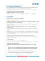
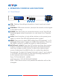
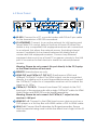
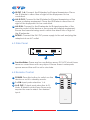
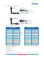
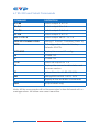
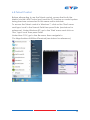
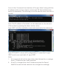
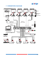
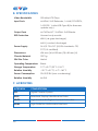
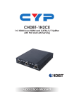
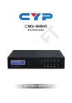
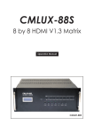
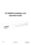
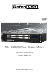
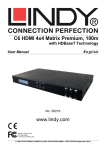
CMSI-424E HDBaseT™ 4×4 HDMI Matrix over 4 CAT5e/6/7 with 2 HDMI Outputs 5-Play™ Operation Manual DISCLAIMERS The information in this manual has been carefully checked and is believed to be accurate. Cypress Technology assumes no responsibility for any infringements of patents or other rights of third parties which may result from its use. Cypress Technology assumes no responsibility for any inaccuracies that may be contained in this document. Cypress also makes no commitment to update or to keep current the information contained in this document. Cypress Technology reserves the right to make improvements to this document and/or product at any time and without notice. COPYRIGHT NOTICE No part of this document may be reproduced, transmitted, transcribed, stored in a retrieval system, or any of its part translated into any language or computer file, in any form or by any means— electronic, mechanical, magnetic, optical, chemical, manual, or otherwise—without express written permission and consent from Cypress Technology. © Copyright 2011 by Cypress Technology. All Rights Reserved. Version 1.1 August 2011 TRADEMARK ACKNOWLEDGMENTS All products or service names mentioned in this document may be trademarks of the companies with which they are associated. SAFETY PRECAUTIONS Please read all instructions before attempting to unpack, install or operate this equipment and before connecting the power supply. Please keep the following in mind as you unpack and install this equipment: • Always follow basic safety precautions to reduce the risk of fire, electrical shock and injury to persons. • To prevent fire or shock hazard, do not expose the unit to rain, moisture or install this product near water. • Never spill liquid of any kind on or into this product. • Never push an object of any kind into this product through any openings or empty slots in the unit, as you may damage parts inside the unit. • Do not attach the power supply cabling to building surfaces. • Use only the supplied power supply unit (PSU). Do not use the PSU if it is damaged. • Do not allow anything to rest on the power cabling or allow any weight to be placed upon it or any person walk on it. • To protect the unit from overheating, do not block any vents or openings in the unit housing that provide ventilation and allow for sufficient space for air to circulate around the unit. REVISION HISTORY VERSION NO. DATE DD/MM/YY SUMMARY OF CHANGE RDV1 13/09/12 Preliminary Release VS1 11/07/12 Updated format/diagrams CONTENTS 1. Introduction�������������������������������������������� 1 2. Applications������������������������������������������� 1 3. Package Contents�������������������������������� 1 4. System Requirements���������������������������� 2 5. Features�������������������������������������������������� 2 6. Operation Controls and Functions������� 3 6.1 Front Panel�����������������������������������������3 6.2 Rear Panel�����������������������������������������4 6.3 Side Panel������������������������������������������5 6.4 Remote Control���������������������������������5 6.5 IR Pin Assignment������������������������������6 6.6 RS-232 Protocols��������������������������������6 6.7 RS-232 and Telnet Commands��������7 6.8 Telnet Control������������������������������������8 6.9 Web GUI Control�����������������������������10 7. Connection Diagram�������������������������� 12 8. Specifications�������������������������������������� 13 9. Acronyms��������������������������������������������� 13 1. INTRODUCTION The HDBaseT™ 4 by 4 HDMI Matrix over CAT5e/6/7 with two additional simultaneous HDMI outputs supports the transmission of video (resolutions up to 1080p Full HD and 1920x1200@60Hz), multi-channel digital audio and control via IR, RS-232 or Web GUI/Telnet IP from four high definition sources to four HDBaseT outputs over a single CAT5e/6/7 cable (up to 100m) for each output. Output A and C have additional mirrored HDMI outputs. It supports high resolution digital audio formats such as LPCM 7.1 CH, Dolby TrueHD, Dolby Digital Plus and DTS-HD Master Audio as well as 3D content that can be displayed when connecting a 3DTV and 3D source. Power over Ethernet (PoE) support means that compatible receivers do not need their own seperate power supplies, allowing for greater flexibility in installations and the LAN serving function allows devices such as Smart TVs to be connected to the network/internet. 2. APPLICATIONS • Domestic HDMI Matrix system • Video/TV wall display and control • Security surveillance and control • Commercial advertising, display and control • University Lecture hall display and control • Retail Sales and demonstration 3. PACKAGE CONTENTS • 4x4 HDMI Matrix over 4 CAT5e/6/7 with 2 HDMI outputs • 1×IR Extender Cable* • 1×IR Blaster Cable* • 1×24V/3.75A DC adaptor • 1×Remote control • Operation manual *Additional IR Blasters and extenders can be purchased seperately 1 4. SYSTEM REQUIREMENTS • HDMI equipped source devices, connect with HDMI cables or DVI equipped source, connect with DVI to HDMI cables • HDMI equipped displays (TVs or monitors) or HDMI equipped AV receivers, connect with HDMI cables • Industry standard CAT5e/6/7 cables • HDBaseT™ Receivers (i.e. CH-506RX, CH-507RX or CH-1109RX) 5. FEATURES • HDMI, HDCP 1.1 and DVI compliant • Supports HDMI 3D features • Supports resolutions VGA~WUXGA and 480i~1080p dependent upon the output display’s EDID settings • Supports distances up to 100 meters through CAT6/7 cables and 80m for CAT5e • Supports 3D signal display dependent upon the output display's EDID settings • Supports simultaneous HDMI and CAT 5e/6/7 display on outputs A and C • Supports PoE* (Power over Ethernet) on compatible receivers only • Supports HDMI input up to 15 meters at 8-bit resolution or 10 meters at 12-bit resolution • Supports bi-directional IR from input and output locations • Supports RS-232, remote control, on-panel control and IP Control (Telnet or Web GUI) • 1U size design • Supports external and internal EDID settings • Supports LPCM 7.1CH, Dolby TrueHD, Dolby Digital Plus and DTS-HD Master Audio transmission • Supports LAN serving function through the LAN/CONTROL port Note: 1. The PoE function is designed for powering compatible receiver units only—non-PoE receivers will need their own power supply. Receivers of another brand may not be compatible. 2. Do not connect the LAN port to CAT outputs of this device or to CAT inputs or receiver. Doing so may demage the unit. 2 6. OPERATION CONTROLS AND FUNCTIONS 6.1 Front Panel POWER LOCK MENU CMSI-424E 4X4 HDMI MATRIX 1 2 3 4 5 A 1 B 2 OUT C 3 D 4 IN 6 1 LCM : Displays the setting information of each input and output setting. 2 IR Window: IR Receiver window (accepts the remote control signal of this device only). 3 POWER: Press this button to power the device on/off. The LED will illuminate green when the power is on, red when it is in 'Standby' mode. 4 LOCK: Press this button to lock all the buttons on the panel; press again to unlock. The LED will illuminate when locked. 5 MENU: Press once to select EDID setting from STD (internal) 1 or TV (external) 2 then press it again to confirm the selection. Press the the 'MENU' button to confirm the input or output selection 6 IN/OUT and 1~4/A~D: Press the OUT button and then the number buttons to select the required output ports, and press IN button and then a single number button to select the required input source, finally press the MENU button to confirm the selection. For example, if outputs A~B need to be set to input 1 and outputs C~D need to be set to input 2, then the following sequence of button presses need to be performed: Press: OUTABIN1→MENU, and then press: OUTCDIN2MENU. Note: If the menu button is not pressed the selection will not be changed. 3 6.2 Rear Panel 4 A 7 B 1 9 2 C 4 3 D RS232 HDMI OUT CAT5e/6 OUT CAT5e/6 OUT IR IN IR OUT IR OUT IR IN IR OUT IR IN IR OUT HDMI OUT HDMI IN 1 2 3 CAT5e/6 OUT ALL IR OUT GND GND V+ CAT5e/6 OUT 2 1 4 3 +V GND IR IN SERVICE IP & ETHERNET 1 IR IN HDMI IN 2 HDMI IN 3 6 5 HDMI IN 4 DC 24V 8 10 11 1 RS-232: Connect to a PC or control system with D-Sub 9-pin cable for the transmission of RS-232 commands. 2 IP & ETHERNET: Connect to an active network for LAN serving and Telnet/Web GUI control (refer to Sections 6.8 and 6.9).When the Matrix or any compatible LAN equipped receivers are connected to a network, this allows the network access (including internet access if available) to be shared between the Matrix and all connected LAN equipped receivers. Connect any Ethernet equipped device such as a Smart TV or games console to the LAN port of a receiver for that device to share the network/internet access. Warning: Please do not connect this port directly to the PC/Laptop as the Telnet function will not work. 3 SERVICE: Manufacturer use only. 4 HDMI OUT and CAT5e/6/7 OUT A/C: Simultaneous HDMI and HDBaseT CAT5e/6/7 output. The HDMI output can be connected directly to a display or to a point transmitter/receiver set. Connect the CAT5e/6/7 output to a compatible receiver unit to extend the signal up to 100 m. 5 CAT5e/6/7 OUT B/D: Connect from these CAT outputs to the CAT input port of the receiver units with a single CAT5e/6/7 cable for HDMI Audio/Video and IR/RS-232 control signal transmission. Warning: Please do not connect the CAT5e/6/7 output into the receiver's LAN port. 6 HDMI IN 1~4: Connect to the HDMI input source devices such as a DVD player or a Set-top Box with HDMI cable or DVI to HDMI cable. 7 IR IN 1~4: Connect the IR extenders for IR signal reception. Ensure that the remote being used is within the direct line-of-sight of the IR extender. 4 8 IR OUT 1~4: Connect the IR blasters for IR signal transmission. Place the IR blaster in direct line-of-sight of the equipment to be controlled. 9 ALL IR OUT: Connect to the IR blaster for IR signal transmission of the source or display equipment. Place the IR blaster in direct line-ofsight of the equipment to be controlled. 10 ALL IR IN: Connect to the IR extender for IR signal reception of the remote control of this device or the source and display equipment. Ensure that remote being used is within the direct line-of-sight of the IR extender. 11 DC24V: Connect the 24 V DC power supply to the unit and plug the adaptor into an AC outlet. 6.3 Side Panel 1 1 Fan Ventilator: These are fan ventilation areas, DO NOT block these areas or cover them with any object. Ensure there is adequate space around the unit for air to circulate. 6.4 Remote Control 1 POWER: Press this button to switch on the device or set it to standby mode. 2 1~4 IN: Input ports selection 1~4. 3 A~D OUT: Output ports selection A~D. Note: IR Matrix control from Zones only require the user to select the desired input. 1 2 1 A 2 B 3 C 4 D IN OUT CR-121 5 3 6.5 IR Pin Assignment IR Blaster 1 Power 5 V 2 IR Blaster Signal 3 NC IR Extender 1 IR Signal 2 Power 5 V 3 Grounding 6.6 RS-232 Protocols 4 HDMI MATRIX REMOTE CONTROL PIN Assignment PIN Assignment 1 NC 1 NC 2 Tx 2 Rx 3 Rx 3 Tx 4 NC 4 NC 5 GND 5 GND 6 NC 6 NC 7 NC 7 NC 8 NC 8 NC 9 NC 9 NC Baud Rate: 19200bps Data bit: 8 bits Parity: None Flow Control: None Stop Bit: 1 6 6.7 RS-232 and Telnet Commands COMMAND DESCRIPTION A1~A4 Switch output A to 1~4 B1~B4 Switch output B to 1~4 C1~C4 Switch output C to 1~4 D1~D4 Switch output D to 1~4 AB...1~CD...4 Switch output ABCD... to 1~4 SETIP<IP><SubNet><GW> Setting IP. SubNet. GateWay (Static IP) RSTIP IP Configuration: Reset to Factory Defaults <DHCP> IPCONFIG Display the current IP config P0 POWER OFF P1 POWER ON I1~I4 Switch all outputs to 1~4 ST Displays the current matrix status and firmware version RS System Reset to A1, B2, C3 & D4 EM Setting EDID MODE. 1=STD, 2=TV ? Display all the available commands Quit Exit (for telnet only) Note: All the commands will not be executed unless followed with a carriage return. All letters are case-insensitive. 7 6.8 Telnet Control Before attempting to use the Telnet control, ensure that both the Matrix (via the LAN/Control port) and the PC/Laptop or control system being used are connected to the same active network. To access the Telnet control in Windows 7, click on the 'Start' menu and type 'cmd' in the Search Field then press Enter (see below for reference). Under Windows XP, go to the 'Start' menu and click on 'Run', type 'cmd' then press Enter. Under Mac OS X, go to the file menu then navigate to GoApplicationsUtilitiesTerminal (see below for reference.) 8 Once in the Command Line Interface (CLI) type 'telnet' along with the IP address of the unit you wish to control and '23' then hit Enter (see below for reference). This will bring us into the device which we wish to control. Note: The IP address of the Matrix can be displayed on the device's LCM monitor by pressing the Menu button twice. Type 'HELP' to list the available commands (see below for reference). Type 'IPCONFIG' To show all IP configurations. To reset the IP, type 'RSTIP' and to use a set static IP, type 'SETIP'. Note: 1. All commands will not be executed unless followed by a carriage return. Commands are case-insensitive. 2. If the IP is changed then the IP Address required for Telnet/ WebGUI access will also needs to be changed accordingly. 6.9 Web GUI Control On a PC/Laptop or control system that is connected to the same active network as the Matrix, open a web browser and type device's IP address on the web address entry bar. The browser will display the device's status, and the control and user settings pages. Click on the 'Control' tab to control power, input/output ports, EDID and reset mode. Click on the 'User Setting' tab allows you to reset the IP configuration. The system will ask for a reboot of the device every time any of the settings are changed. The IP address needed to access the Web GUI control will also need to be changed accordingly on the web address entry bar. 11 7. CONNECTION DIAGRAM ZONE A ZONE B ZONE C ZONE D Projector Displays HDMI Outputs IR Out/In RX Power Link IR 2 IR 1 Extender Blaster RS232 Out CAT5e/6 In RX Power RX Link IR 2 IR 1 Extender Blaster RS232 Out CAT5e/6 In Power RX Link IR 2 IR 1 Extender Blaster RS232 Out CAT5e/6 In Power RX Link IR 2 IR 1 Extender Blaster RS232 Out CAT5e/6 In Power Link IR 2 IR 1 Extender Blaster RS232 Out CAT5e/6 In Receiver Units CAT5e/6/7 Cable TX RS-232 In HDMI In LAN Transmitter HDMI to CAT5e/6 with LAN/IR/RS232 Simultaneous HDMI Output CAT5e/6/7 Cables (100m) RS-232 Power Supply A B 1 2 C 4 3 D RS232 HDMI OUT LAN CAT5e/6 OUT CAT5e/6 OUT IR IN IR OUT LAN IR OUT IR IN IR OUT IR IN IR OUT HDMI OUT CAT5e/6 OUT ALL IR OUT GND GND V+ CAT5e/6 OUT 2 1 4 3 +V GND IR IN HDMI IN 1 RS-232 Equipped PC or Control System IR IN SERVICE HDMI IN 2 HDMI IN 3 HDMI IN 4 DC 24V IR IN (ALL) 1 2 3 4 HDMI Inputs IR In/Out IR OUT (ALL) Simultaneous HDMI Output Router (with Internet Connection) AV Receiver 1.5m 60° IR BLASTER 60° 3m 7m m 3m IR EXTENDER Blu-ray Player Media Server Satellite Receiver Set-top Box 12 8. SPECIFICATIONS Video Bandwidth 225 MHz/6.75 Gbps Input Ports 4×HDMI, 5×IR Extender, 1×LAN/CONTROL, 1×RS-232, 1×Mini-USB Type B(for firmware update only) Output Ports 4×CAT5e/6/7, 2×HDMI, 5×IR Blaster ESD Protection Human body model: ±8 kV (air-gap discharge) ±4 kV (contact discharge) Power Supply 24 V/3.75 A DC (US/EU standards, CE/ FCC/UL certified) Dimensions 436 mm (W)×255 mm (D)×48 mm (H) Chassis Material 3372 g Silk Skin Color Metal Operating Temperature Black Storage Temperature 0 ˚C~40 ˚C/32 ˚F~104 ˚F Relative Humidity −20 ˚C~60 ˚C/−4 ˚F~140 ˚F Power Consumption 20~90 % RH (non-condensing) Relative Humidity 64.2 W 9. ACRONYMS ACRONYM COMPLETE TERM DTS Digital Theater System EDID Extedned Display Identification Data HDCP High-bandwidth Digital Content Protection HDMI High-Definition Multimedia Interface 13 CYPRESS TECHNOLOGY CO., LTD Home page: http://www.cypress.com.tw