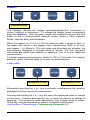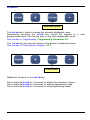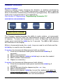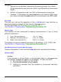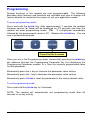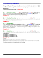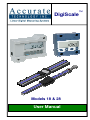
1
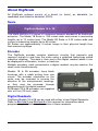
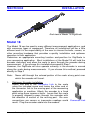
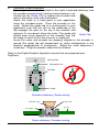
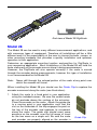
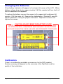
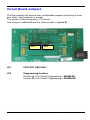
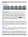
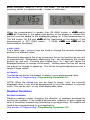
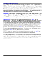
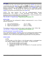
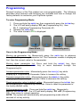
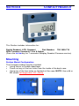
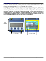
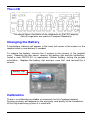
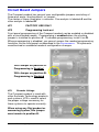
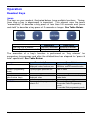
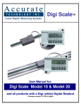
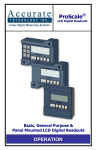
DigiScale
Models 18 & 28
User Manual
™
DigiScale Manual Part # 800-1404-001
Page 2 of 36
WARRANTY
Accurate Technology, Inc. warrants the DigiScale Models 18 & 28 against
defective parts and workmanship for 1 year commencing from the date of
original purchase. Upon notification of a defect, Accurate Technology, Inc.,
shall have the option to repair or replace any defective part. Such services
shall be the customer's sole and exclusive remedy. Expenses incidental to
repair, maintenance, or replacement under warranty, including those for labor
and material, shall be borne by Accurate Technology, Inc. (Including freight
or transportation charges during the first 30 days).
Except as expressly provided in this warranty, Accurate Technology, Inc.
does not make any warranties with respect to the product, either expressed
or implied, including implied warranties of merchantability or fitness for a
particular purpose, except as expressly provided in this agreement.
Accurate Technology, Inc. shall not be liable for any special, incidental, or
consequential damages or for loss, damage or expense directly or indirectly
arising from the customer's use of or inability to use the equipment either
separately or in combination with other equipment, or for personal injury or
loss or destruction of other property, or from any other cause.
To request repair work, (either warranty qualified parts or not) contact
Accurate Technology, Inc. directly by phone, fax, or e-mail. A Returned
Merchandise Authorization (RMA) number is required before returning a
product for repair.
Accurate Technology, Inc.
+1 828.654.7920
www.proscale.com
800.233.0580 828.654.8824 (F)
[email protected]
SAFETY WARNING
Before installing DigiScale on any machinery:
Turn off machine and disconnect power.
SAFETY WARNING
P/N 800-1404-001, Copyright © 2008, Accurate Technology, Inc. All rights reserved.
Accurate Technology DigiScale Models 18 & 28 User Manual
Page 3 of 36
Table of Contents
SECTION 1
GENERAL INFORMATION................................................. 6
INTRODUCTION........................................................................................... 6
ABOUT THIS MANUAL .................................................................................. 6
SPECIFICATIONS......................................................................................... 6
SPECIFICATIONS......................................................................................... 7
ABOUT DIGISCALE...................................................................................... 8
Scale .................................................................................................... 8
Encoder................................................................................................ 8
Digital Readouts ................................................................................... 8
SECTION 2
INSTALLATION.................................................................. 9
MODEL 18 ................................................................................................. 9
MODEL 28 ................................................................................................11
FREQUENTLY ASKED QUESTIONS ................................................................13
SECTION 3
DIGI READOUT ................................................................14
MOUNTING ...............................................................................................14
THE LCD .................................................................................................15
CHANGING THE BATTERIES .........................................................................16
CALIBRATION ............................................................................................16
CIRCUIT BOARD JUMPERS ..........................................................................17
OPERATION ..............................................................................................18
Readout Keys......................................................................................18
TIMING ..............................................................................................18
ON/OFF..............................................................................................18
UNITS KEY..........................................................................................18
+ AND - KEYS .....................................................................................19
DATUM KEY ........................................................................................19
Readout Functions...............................................................................19
REVERSE READINGS ............................................................................19
INCREMENTAL MEASUREMENTS ............................................................20
KEY LOCK ..........................................................................................21
RESOLUTION ......................................................................................21
RESTORE READOUT TO FACTORY SETTINGS ...........................................21
ERROR CODES....................................................................................21
PROGRAMMING .........................................................................................22
Programming Parameters....................................................................23
Pr 1 – Datum Key Value...................................................................23
Pr 2 – Reading Direction ..................................................................23
Pr 3 – Key Lockout...........................................................................23
Pr 4 – Resolution..............................................................................23
DigiScale Manual Part # 800-1404-001
Page 4 of 36
SECTION 4
COMPACT READOUT .............................................24
MOUNTING ...............................................................................................24
Surface Mount Configuration................................................................24
Panel Mount Configuration...................................................................25
THE LCD .................................................................................................26
CHANGING THE BATTERY ...........................................................................26
CALIBRATION ............................................................................................26
CIRCUIT BOARD JUMPERS ..........................................................................27
OPERATION ..............................................................................................28
Readout Keys......................................................................................28
TIMING ..............................................................................................28
IN/MM KEY..........................................................................................29
+ AND - KEYS .....................................................................................29
DATUM KEY ........................................................................................30
Readout Functions...............................................................................31
REVERSE READINGS ............................................................................31
INCREMENTAL MEASUREMENTS ............................................................31
KEY LOCK ..........................................................................................32
RESOLUTION ......................................................................................32
RESTORE READOUT TO FACTORY SETTINGS ...........................................32
ERROR CODES....................................................................................32
PROGRAMMING .........................................................................................33
Programming Parameters....................................................................34
Pr 1 – Datum Key Value...................................................................34
Pr 2 – Reading Direction ..................................................................34
Pr 3 – Key Lockout...........................................................................34
Pr 4 – Resolution..............................................................................34
Accurate Technology DigiScale Models 18 & 28 User Manual
Page 5 of 36
SECTION 1
GENERAL INFORMATION
Introduction
DigiScale is a general purpose linear measuring system It consists of three
major parts: a SCALE, an ENCODER and a DIGITAL READOUT.
DigiScale is an ideal choice for most measuring requirements up to 60 inches
where affordable digital precision (better than a tape measure) is desired.
Because DigiScale shows the exact measurement on its readout, it
eliminates the ambiguity and mistakes involved when reading and
interpreting tape measures, scales & pointer, or shaft encoders.
Because DigiScale is a solid-state electronic device there's very little to wear
out. The encoder and scale are designed to withstand shop dirt, dust, and
other airborne contaminants. With normal care, DigiScale will last for years.
About This Manual
• This manual includes theory and INSTALLATION information for DigiScale
Models 18 & 28 Scales and Encoders.
• This manual includes OPERATION information for the Digi and the
Compact Readouts used with DigiScale systems.
Digi Readout Part # 700-1600-D55
With Firmware Version d 2.xxx & higher
(Firmware version is displayed on power-up)
2AA alkaline batteries
Side input
Compact Readout Part # 700-1600-710
With Firmware Version b 1.xxx & higher
(Press and hold the DATUM key for 7 seconds to
display the firmware version.)
1 CR123 Lithium battery
Rear input
Surface or panel mount
DigiScale Manual Part # 800-1404-001
Page 6 of 36
Specifications
Measuring Range: *
Model 18
Model 28
up to 10 inches
up to 60 inches
Accuracy:
Model 18
Model 28
± .010 inches
± .012 Inches
Readout Resolution
.1inch
.1mm
or
.01inch .01mm
or
.001inch .01mm
or
1/16, 1/32 or 1/64 inch
Repeatability:
.001inch or .01mm
Readout Range:
+ 999.999 in; + 399 63/64 in; + 9999.99 mm
Operating Power:
Digi Readout
2 AA Alkaline Batteries
Compact Readout 1 CR123 Lithium Battery
Operating Temp:
40 to 110°F
Slew Rate:
60 inches/second
Encoder cable:
72 inch
* MEASUREMENT range is approximately 4 inches shorter than the PHYSICAL
length of the aluminum scale extrusion.
Accurate Technology DigiScale Models 18 & 28 User Manual
Page 7 of 36
About DigiScale
All DigiScale systems consist of a SCALE (or track), an
readhead) and a DIGITAL READOUT (DRO).
ENCODER,
(or
Scale
DigiScale Models 18 & 28
The scale consists of a series of conductive patterns bonded to an aluminum
extrusion. The Model 18 Scale is .765 inches wide and comes in measuring
lengths up to 10 inches long. The Model 28 Scale is 2.02 inches wide and
comes in measuring lengths up to 60 inches.
All Scales are approximately 4 inches longer in their physical length than
their measuring range.
Encoder
The DigiScale encoder contains electronic circuitry that transmits and
receives signals to and from the scale using a patented technology called
inductive coupling. This data is then sent to the digital readout where it can
be displayed in millimeters, inches, or fractions.
Multiple encoders, each connected to a digital readout, may be used on the
same scale simultaneously.
Models 18 & 28 encoders have black
housings with a cable exiting from one
corner. The encoder orientation on the
scale may be reversed to reverse the
direction of the measurement readings,
or they may be reversed through
programming in the digital readout.
All Models 18 & 28 encoders are supplied
with a 6 foot (72 inch) cable.
Digital Readouts
DigiScale Models 18 & 28 can be used with either of two Digital Readouts.
Refer to SECTION 3 and SECTION 4 of this manual for information about
programming, installation and operation of these readouts.
DigiScale Manual Part # 800-1404-001
Page 8 of 36
SECTION 2
INSTALLATION
End view of Model 18 DigiScale
Model 18
The Model 18 can be used in many different measurement applications, and
with numerous types of equipment. Therefore all installations will be a little
different and it is the responsibility of the user to choose the bolts, screws, or
other mounting hardware that provides a quality installation and optimum
operation in their application.
Determine an appropriate mounting location and position for DigiScale in
your measuring application. Most installations of the Model 18 will hold the
encoder stationary and allow the scale to pass through the encoder during
measurement. If you choose this installation proceed to Step 1.
However, the DigiScale will also operate correctly is the encoder is moved
along the scale during measurements. If you choose this method, proceed
directly to Step 2
Note:
1.
Never drill through the colored portion of the scale at any point over
which the encoder will travel.
Stationary Encoder installation
Attach one end of the Connector Link to the scale
using the included screw and fasten the other end of
the connector link to the moving part of the measuring
application or machine. Attach the encoder to a fixed
point using three screws or bolts. Insure that the scale
is properly aligned to pass through the encoder with
the direction of motion of the moving part. Be sure
connections are secure or inaccurate readings could Connector Link
result. Plug the encoder cable into the readout.
Accurate Technology DigiScale Models 18 & 28 User Manual
Page 9 of 36
2.
Stationary Scale installation
If your application is better suited for the scale to be held stationary and
the encoder moved along it during a measurement, you
should use the Guide Clip to capture the encoder and
move it along the scale (see illustration).
Attach the scale to a fixed point in your application
using the included screw. Place the encoder on the
scale. Attach the guide clip to a moving point in your
application such that the slot on the underside of the
clip engages the post on the top of the encoder and
captures it’s movement along the scale. The guide clip
Guide Clip
should exert some pressure on the encoder over the
full range of travel as the two move as a single unit.
Insure the scale and encoder are properly aligned as the encoder is
moved (the guide clip will compensate for slight misalignment in the
direction perpendicular to movement). Adjust the scale alignment if
necessary. Plug the encoder cable into the readout.
Refer to the Digital Readout Operation manual that accompanied your
DigiScale.
Moving Part
Connector Link
Encoder
Scale
Encoder stationary, Scale moving
M ov ing pa rt
E nco de r
G uide C lip
S cal e
Scale stationary, Encoder moving
DigiScale Manual Part # 800-1404-001
Page 10 of 36
End view of Model 28 DigiScale
Model 28
The Model 28 can be used in many different measurement applications, and
with numerous types of equipment. Therefore all installations will be a little
different and it is the responsibility of the user to choose the bolts, screws, or
other mounting hardware that provides a quality installation and optimum
operation in their application.
Determine an appropriate mounting location and position for DigiScale in
your measuring application. Most installations of the Model 28 will hold the
scale stationary as the encoder moves along it during measurement.
However, the DigiScale will also operate correctly if the scale is moved
through the encoder during measurements; however this type of installation
is not recommended for the Model 28.
Note:
Never drill through the colored portion of the scale at any point over
which the encoder will travel.
When installing the Model 28 you should use the Guide Clip to capture the
encoder movement along the scale (see illustrations).
1. Attach the scale to a fixed point in your application
using the included screws. Be sure the screw heads
do not protrude above the surface of the extrusion.
Place the encoder on the scale. Attach the guide clip
to a moving point in your application such that the
slot on the underside of the clip engages the post on
the top of the encoder and captures its movement
along the scale. The guide clip should exert some
pressure on the encoder over the full range of travel
as the two move as a single unit. Be sure the scale
and encoder are properly aligned as the encoder is
Accurate Technology DigiScale Models 18 & 28 User Manual
Guide Clip
Page 11 of 36
moved (the guide clip will compensate for slight misalignment in the
direction perpendicular to movement). Adjust the scale alignment if
necessary. Plug the encoder cable into the readout.
Refer to the Digital Readout OPERATION manual that accompanied your
DigiScale.
M o v in g P a r t
G u i d e C l ip
E n co de r
M o d e l 2 8 S ca le
G u id e C li p
E ncod er
( .8 3 " )
M od el 28
S c a le
( 1 .3 " )
Typical Model 28 Installation
DigiScale Manual Part # 800-1404-001
Page 12 of 36
Frequently Asked Questions
Can I mount the Scale/Encoder without the connector link/guide clip?
Yes. However, the connector link and guide clip serve to provide an
accurate method of transferring the movement of the encoder or
scale, while also absorbing any stresses that may occur. If they are
not used, your system could be damaged and the warranty could
be voided.
What does no Enc mean?
If the encoder is off the scale, or unplugged from the readout,
a no Enc will appear on the readout. To clear the error:
1. Be sure the encoder is on the scale.
2. Plug the encoder into the readout.
3. Unplug the encoder from the readout for one second then
reconnect it.
How do I calibrate my DigiScale?
There is no calibration available or necessary for the DigiScale.
System accuracy will depend on the accuracy of the DigiScale Scale
itself and the quality of the installation.
Accurate Technology DigiScale Models 18 & 28 User Manual
Page 13 of 36
SECTION 3
DIGI READOUT
This Section includes information for:
Digital Readout, LCD, DIGI
Part Number:
With Firmware Version d 2.xxx & higher
(Firmware version is displayed on power-up)
700-1600-D55
Mounting
The Readout may be mounted:
• Using Velcro or Double sided tape
• Drilling out the 3 holes from the inside of the case
• Using any of the six holes on the back of the case which may tapped for
M2 or 4-40 screws.
DigiScale Manual Part # 800-1404-001
Page 14 of 36
The LCD
The above figure illustrates all the segments available on the Dig Readout.
(Not all segments are used)
CAUTION
Pressing and holding the ON/OFF and UNITS key for 10 seconds
with power off will perform a full segment LCD test, display the
current firmware version, and RESET ALL PROGRAMMING
PARAMETERS TO FACTORY DEFAULTS.
Accurate Technology DigiScale Models 18 & 28 User Manual
Page 15 of 36
Changing the Batteries
A low battery indicator will appear in the lower left corner of the LCD. When
battery voltage drops below approximately 2.6V the readout will turn itself off
until the batteries are replaced.
To replace the battery remove the screws in the upper right and lower left
corners. Pull the cover off. Remove the old batteries. Reinstall 2 new AA
Alkaline batteries, noting the proper orientation. Replace the cover and
tighten the screws.
CAUTION: DO NOT BEND THE BATTERY CLIPS!
THESE CLIPS ARE DESIGNED TO BE LOOSE WHEN THE CASE
IS OPEN AND WILL COMPRESS AND SECURE THE BATTERIES
IN PLACE WHEN THE CASE HALVES ARE SCREWED TOGETHER.
Calibration
There is no calibration available or necessary for the DIGI readout.
System accuracy will depend on the accuracy of the DigiScale and the
quality of the installation.
DigiScale Manual Part # 800-1404-001
Page 16 of 36
Circuit Board Jumpers
The Digi readout has several user configurable jumpers consisting of three
pins and a ‘shorting block or jumper’.
The center of these three pins is ‘Common’.
One end pin is labeled A and the other end pin is labeled B.
JP1
JP2
JP1
FACTORY USE ONLY
JP2
Programming Lockout
Position A, Front Panel Programming is ENABLED
Position B, Front Panel Programming is DISABLED
Accurate Technology DigiScale Models 18 & 28 User Manual
Page 17 of 36
Operation
Readout Keys
TIMING
The keys pictured above, are found on all Digi readouts, and some of them
have multiple functions.
Timing, which is how long a key is depressed, and the combination of the
keys pressed is important. This manual uses the term ‘”momentarily” to
describe a key press of shorter than 1 second. Whereas the term “press and
hold” is used to describe a key press of longer than 1.5 seconds. As an
example; when using a PC keyboard to type a capital letter you would “press
and hold” the SHIFT key and “momentarily depress the LETTER key. In
addition most of the key “functions” are executed on RELEASE, not press.
This is important since some of the same keys execute different functions
based on how long they are pressed and when they are released. These key
operations, once tried will quickly become intuitive.
ON/OFF
Momentarily pressing the ON/ OFF key will cause the readout to turn on or off.
The Firmware Version of the readout is displayed on power-up when ON/ OFF
key is used. While the readout is on, if the encoder is not moved for 15
minutes, the readout will automatically turn itself off to conserve battery life.
While it is off if the encoder is moved as little as .002in (.05mm), or the
ON/OFF key is pressed, the readout will automatically turn itself back on with
no loss of position.
UNITS KEY
The readout can display position information in decimal inches, fractions, or
millimeters. To change the current display mode, momentarily press the
UNITS key. With each key press the readout will cycle through decimal
inches, fractional inches and millimeters.
When the readout is in 1/16 or 1/32 inch fraction mode, a series of “bars” in
the upper right corner of the display, each representing 1/64th of an inch,
may appear. (ie. When in 1/16 inch mode and three bars are showing, the
measurement displayed is rounded down to the closest 1/16 inch and each
illuminated bar indicates an additional 1/64 of an inch of measurement.) For
DigiScale Manual Part # 800-1404-001
Page 18 of 36
better resolution, switch to 1/32 or 1/64 mode. For the best resolution and
accuracy switch to a decimal mode – inches or millimeters.
When the measurement is greater than 99 63/64 inches, a +100 and/or
+200 will illuminate in the upper right portion of the display to indicate this
amount must be added to the displayed reading. ie: If the measurement is
154 5/8 inches, 54 5/8 and +100 will be illuminated on the display. If the
measurement is -307 23/64 inches, - 7 23/64, +100 and +200 will be
illuminated on the display.
+ AND - KEYS
The + (plus) and – (minus) keys are used to change the currently displayed
position to a different value.
Momentarily depressing the + key increments the current position by one unit
of measurement. Momentarily depressing the – key decrements the current
position by one unit. Pressing and holding the + or – keys will cause the
displayed position to change continuously. Holding down the key will cause
the amount of change to speed up. This allows for quick adjustments over a
range of large values.
DATUM KEY
The DATUM
key forces the readout to display a user programmed value.
See Section 3: Programming, Programming Parameter Pr1.
NOTE: While the DATUM key can be used to simply “zero” the currently
displayed value, it can also be programmed to force the readout to a preset
value. This can be zero, or any other displayable value.
Readout Functions
REVERSE READINGS
Reverse readings means changing the direction of readings produced by
moving the encoder. If the readout decrements (reduces or goes negative)
when it should be incrementing (increasing or going positive), the readout will
need to be re-programmed for your application.
See Section 3: Programming, Programming Parameter Pr2.
Accurate Technology DigiScale Models 18 & 28 User Manual
Page 19 of 36
INCREMENTAL MEASUREMENTS
The readout has two measurement modes, or indexes. One is referred to as
ABS or Absolute, and the other as INC, or Incremental. The absolute
measurement mode allows the operator to read the current position of the
encoder referenced from a fixed or known position-usually zero.
The incremental mode allows the operator to make relative distance
measurements from one arbitrary point to another. The absolute position of
the DigiScale is not lost when using the incremental mode.
Absolute: The readout automatically enters ABS mode when power is first
applied. This is indicated by the ABS symbol in the upper left corner of the
display. While in the ABS mode, all encoder positions are related to the
current ABS, or absolute system reference point.
Incremental: To enter the INC mode, press and hold the UNITS key for
approximately 3 seconds. The INC symbol will appear in the upper left corner
of the display. When the INC mode is entered the readout will display zero
(0) or the last offset if one was entered, and may be changed by using the +
or - keys to provide a different offset. Moving the encoder in either direction
will display the distance moved from the initial INC starting point (plus any
offset). To complete another incremental measurement from the new
position, momentarily press the UNITS key. The readout will again change to
0 (or the previously programmed offset). To return to the ABS mode, press
and hold the UNITS key for approximately 3 seconds.
NOTES: when the readout is in incremental measuring mode the UNITS key
no longer functions to change the measurement units displayed.
The absolute position of the DigiScale is not lost when using the incremental
mode. When the readout is switched back to the absolute mode the readout
reflects the current encoder position relative to your original calibrated
absolute setting.
DigiScale Manual Part # 800-1404-001
Page 20 of 36
KEY LOCK
To activate the Key Lock function press and hold the ON/OFF key and then
momentarily press the UNITS key. The word LOCK will appear in the upper left
corner of the readout. When LOCK is displayed, the +, DATUM and – keys
become inactive to prevent accidental changes of the (calibrated) current
displayed position. To de-activate the Lock function, press and hold the
ON/OFF key and then momentarily press the UNITS key.
NOTE: The Lock function can also be enabled/disabled through
programming. This allows a more permanent Lock function since
programming can be disabled with a hardware jumper inside the readout thus
preventing any front panel programming changes.
See Section 3: Programming, Programming Parameter Pr3.
RESOLUTION
The readout can be configured to display measurements in any of three
different resolutions.
1. Low– the resolution is:
2. Normal– the resolution is:
3. High– the resolution is:
.1in or .1mm.
.01in or .01mm.
.001in or .01mm
The display of fractions remains the same for all settings: 1/16, 1/32 & 1/64
See Section 3: Programming, Programming Parameter Pr4.
RESTORE READOUT TO FACTORY SETTINGS
Press and hold the ON/OFF and UNITS keys
for 10 seconds with readout power
turned off. This will perform a full segment LCD test, display the current
firmware version, and reset all programming parameters to factory defaults.
ERROR CODES
no Enc
If the Encoder is off the Scale, or the Encoder cable is unplugged from
the readout, no Enc will appear on the display. To clear the error:
1. Be sure the encoder is on the scale.
2. Connect the encoder to the readout.
3. Unplug the encoder from the readout for 5 seconds and then
reconnect.
Accurate Technology DigiScale Models 18 & 28 User Manual
Page 21 of 36
Programming
Several functions of the Digi readout are user programmable. The following
describes what features and functions are available and how to change the
factory defaults to customize your DigiScale system.
To enter Programming Mode:
1. Press and hold the UNITS key then momentarily press the DATUM key.
2. The LCD will briefly display: PG on (Programming On), then
Pr 1, (indicating Programming Parameter #1)
3. Release the UNITS key
4. The value stored in Pr1 is displayed.
Press & Hold
Momentarily press
Once in the Programming Mode:
Moving up parameter list: Momentarily press the UNITS key to advance
through the Programming Parameter list. The Parameter number is displayed
first, then the current value for the parameter.
Moving down parameter list: Press and hold the ON/ OFF key, then
momentarily press the UNITS key to move backward through the
Programming list.
Increase parameter value - Momentarily press the PLUS (+) key while
displaying a Programming Parameter Value to increase the setting.
Decrease parameter value - Momentarily press the MINUS (-) key while
displaying a Programming Parameter Value to decrease the setting.
Reset parameter value to default setting - Momentarily press the DATUM key
while displaying a Programming Parameter Value to reset the parameter to
the factory default value.
Exit programming mode - Press and hold the UNITS key. Momentarily
depress the DATUM key. The LCD will briefly display: PG oFF (Programming
Off), then return to normal operation.
NOTE: The system will automatically exit programming mode after 60
seconds of no key activity.
DigiScale Manual Part # 800-1404-001
Page 22 of 36
Programming Parameters
The Digi readout programming parameters are listed below.
Values in [ ] are the available range of values that can be entered for that
parameter. Factory defaults are shown in Bold Red.
Pr 1 – Datum Key Value
[0 to + 999.999in] or [0 to +9999.99mm]
The programmed value that will be recalled whenever the DATUM key is
pressed during normal operation.
Default = 0.00
Pr 2 – Reading Direction
[0 or 1]
This parameter controls the direction of travel (positive vs. negative) when
the encoder is moved.
Default = 0
Pr 3 – Key Lockout
[0 or 1]
This parameter controls the operation of the +, - and DATUM keys.
If enabled, (set to 1), these keys will not function and the LOCK symbol will
appear on the display. This prevents accidental changes when pressing
these keys during normal operation.
Default = 0
Pr 4 – Resolution
[1, 2, 3 or 4]
This parameter sets the number of places to the right of the decimal point on
the readout.
A value of 1 – Low - will display x.x.
A value of 2 – Normal - will display x.xx
A value of 3 – High - will display x.xxx
Default = 3
NOTES:
Millimeters have a maximum of 2 places (even if parameter is set to 3.)
This setting has no effect when displaying fractions.
Accurate Technology DigiScale Models 18 & 28 User Manual
Page 23 of 36
SECTION 4
COMPACT READOUT
This Section includes information for:
Digital Readout, LCD, Compact
Part Number: 700-1600-710
With Firmware Version b 1.xxx & higher
(Press the DATUM key for 7 seconds to display Readout Firmware version)
Mounting
Surface Mount Configuration
The Compact readout may be mounted:
• Using Velcro or Double sided tape
• Punch out any of the four holes from the inside of the back case.
• Using any of the four holes on the back of the case. NOTE: Use a #4 or
M3 screw not longer than 3/8 “ (9mm).
DigiScale Manual Part # 800-1404-001
Page 24 of 36
Panel Mount Configuration
A cutout should be made in the panel of at least 2.2 x 1.7 inches, (56 x
43mm) but no larger than 2.6 x 2.0 inches (66 x 50 mm).
Install the readout by screwing the four screws in the each corner of the front
case directly into the panel. The rear half of the readout case is not
necessary when it is used in a panel mounted configuration with a panel of
sufficient thickness to hold the 4 mounting screws. If your panel is too thin to
hold screws, you may ‘sandwich’ the panel between the front and rear halves
of the readout case and install 4 screws long enough to extend through the
entire assembly and into the rear half case of the readout.
2.5
Inches
2.0 Inches
Cut out size
Accurate Technology DigiScale Models 18 & 28 User Manual
Page 25 of 36
The LCD
The above figure illustrates all the segments on the LCD display.
(Not all segments are used on Compact Readouts)
Changing the Battery
A low battery indicator will appear in the lower left corner of the screen on the
readout when a new battery is needed.
To replace the battery, remove the 4 screws in the corners of the readout
case. Separate the two cases, remove the battery clip and the old battery.
Install a new CR123 3V, or equivalent, Lithium battery, noting the proper
orientation. Replace the battery clip and rear case half, and reinstall the 4
screws.
Battery Clip
-
+
Calibration
There is no calibration available or necessary for the Compact readout.
System accuracy will depend on the accuracy, and quality of the installation,
of the Digi measuring system it is used with.
DigiScale Manual Part # 800-1404-001
Page 26 of 36
Circuit Board Jumpers
The Compact readout has several user configurable jumpers consisting of
three pins and a ‘shorting block’ or ‘jumper’.
The center of these three pins is common. One end pin is labeled A and the
other end pin is labeled B.
JP1
FACTORY USE ONLY
JP2
Programming Lock-out
Front panel programming of the Compact readout can be enabled or disabled
with a circuit board jumper. Programming is enabled when the shorting
jumper is installed on position A. To disable programming, install it on B.
When programming is disabled, you cannot access the readout programming
functions via the front panel as described in the PROGRAMMING. This prevents
unauthorized or accidental readout configuration changes.
With Jumper on position A:
Programming is Enabled
With Jumper on position B:
Programming is Disabled
JP3
Encoder Voltage
The Compact readout is used with
other Accurate Technology products
and systems. JP3 is used to select
the proper voltage necessary for
these systems to operate correctly.
When using any Digi product or
measuring system, this jumper
must remain in position B.
Accurate Technology DigiScale Models 18 & 28 User Manual
Page 27 of 36
Operation
Readout Keys
TIMING
The keys on your readout, illustrated below, have multiple functions. Timing,
(how long a key is depressed) is important. This manual uses the terms
“momentarily” to describe a key press of less than 0.8 seconds and “press
and hold” to describe a key press of 2 seconds or longer. See Table Below.
How long a key is pressed?
When is key function is executed?
Momentarily
Less than 0.8 seconds
On key release
Press & Hold
More than 2 seconds
While holding
The execution of a key’s function is performed on “key release” for
momentary key presses and after the allotted time has elapsed for “press &
hold” operations. See Table Below.
Momentarily Press
Cycles measurement units
displayed: inches, fractions, mm
Cycles program parameter list
Press & Hold
3 seconds: Toggles between
ABSolute and INCremental modes
Has no effect
+
(plus & minus keys)
Increments or Decrements
displayed value
Increments or Decrements displayed
value faster
DATUM
Forces readout to programmed
value in Pr 1
7 seconds: Displays FW version
9 seconds: Enters Programming
mode
3 seconds: Exits programming mode
IN/MM
(When in programming
mode)
DigiScale Manual Part # 800-1404-001
Page 28 of 36
IN/MM KEY
Momentarily press
The compact readout can display measurement/position information in
inches, fractions or millimeters. To change the display mode, momentarily
press the IN/MM key. Each key press causes the readout to cycle to the next
mode, or unit of measurement: decimal inches, fractions 16ths, fractions
32nds, fractions 64ths and millimeters.
When the readout is in 1/16 or 1/32 inch fraction mode, a series of “bars” in
the upper right corner of the display, each representing 1/64th of an inch,
may appear. (i.e. When in 1/16 inch mode and three bars are showing, the
measurement displayed is rounded down to closest 1/16 inch and each
illuminated bar would then indicate an additional 1/64 of an inch additional
measurement.)
For better measurement precision, switch to 1/32 or 1/64 mode. For the best
precision select a decimal mode (in or mm) for measurements.
+ AND - KEYS
Momentarily or Hold
Momentarily or Hold
Momentarily pressing the + or - key increments or decrements the currently
displayed value by one unit of measurement.
Pressing and holding the + or - key will cause the displayed value to change
continuously. Continue pressing the key to cause the amount of change to
speed up. This allows for quick adjustments over a large range of values.
These keys may be locked out to prevent accidental offset entries.
See Section 4: Programming, Programming Parameter Pr3
Accurate Technology DigiScale Models 18 & 28 User Manual
Page 29 of 36
DATUM KEY
Momentarily press
The DATUM key is used to change the currently displayed value.
Momentarily pressing the DATUM key forces the readout to a user
programmed value. This can be zero or any other displayable value.
See Section 4: Programming, Programming Parameter Pr1
The DATUM key can also be locked out to prevent accidental entries.
See Section 4: Circuit Board Jumpers, JP 2
Press & Hold
Additional functions of the DATUM key:
Press and hold DATUM for 7 seconds to display the firmware version.
Press and hold DATUM for 9 seconds to enter programming mode.
Press and hold DATUM for 3 seconds to exit programming mode.
DigiScale Manual Part # 800-1404-001
Page 30 of 36
Readout Functions
REVERSE READINGS
Reverse readings means changing the direction of readings produced by
moving the encoder. If the readout decrements (reduces or goes negative)
when it should be incrementing (increasing or going positive), the readout will
need to be re-programmed for your application.
See Section 4: Programming, Programming Parameter Pr2
INCREMENTAL MEASUREMENTS
Press & Hold for 3 seconds
The Compact readout provides the ability to make relative, or incremental,
measurements and still retain the measurements system’s absolute position
in memory. To enter the Incremental (or return to Absolute) measurement
mode, press and hold the IN/MM key for 3 seconds. The ABS or INC indicator
will illuminate on the display.
While in Incremental mode, the + and – keys are used to set offsets and the
DATUM key is used to zero the readout.
Example of an Incremental Measurement (with no offsets):
1) Enter the incremental mode (press and hold the IN/MM key 3
seconds.)
2) Make a measurement.
3) Momentarily depress IN/MM or DATUM key to re-zero the readout
4) Make another measurement
5) Repeat as necessary.
Example of an Incremental Measurement (with offsets):
1) Enter the incremental mode (press and hold the IN/MM key 3
seconds.)
2) Set the desired offset by depressing the + or – key.
3) Make a measurement.
4) Momentarily depress IN/MM key to reset the readout and apply the
offset entered previously, or momentarily depress the DATUM key to
re-zero the display before the next measurement.
Accurate Technology DigiScale Models 18 & 28 User Manual
Page 31 of 36
NOTES:
1. Offsets are stored when leaving the Incremental mode. Any offsets
will be recalled the next time you switch from Absolute to Incremental
mode.
2. While in Incremental mode, the Units of Measurement cannot be
changed. If the display is reading mm when you enter the INC mode
you cannot change to inches without first returning to the ABS mode.
KEY LOCK
The user can lock-out the operation of the +, DATUM and – key functions to
prevent accidental changes of the currently displayed value.
To lock these keys set Programming Parameter Pr3 =1
See Section 4: Programming, Programming Parameter Pr3
RESOLUTION
The readout can be configured to display measurements in any of three
different resolutions.
1. Low– the resolution is:
2. Normal– the resolution is:
3. High– the resolution is:
.1in or .1mm.
.01in or .01mm.
.001in or .01mm
The display of fractions remains the same for all settings: 1/16, 1/32 & 1/64
See Section 4: Programming, Programming Parameter Pr4
RESTORE READOUT TO FACTORY SETTINGS
Remove the battery. Press and hold IN/MM
key while reinstalling the battery.
ERROR CODES
no Enc
If the Encoder is off the Scale, or the Encoder cable is unplugged from
the readout, no Enc will appear on the display. To clear the error:
4. Be sure the encoder is on the scale.
5. Connect the encoder to the readout.
6. Unplug the encoder from the readout for 5 seconds and then
reconnect.
DigiScale Manual Part # 800-1404-001
Page 32 of 36
Programming
Several functions of this readout are user programmable. The following
describes what features and functions are available and how to change the
factory defaults to customize the system to suit your application needs.
To enter programming mode:
Press and hold the DATUM key. After approximately 7 seconds the readout
firmware version (b 1.xxx) will be displayed for 2-3 seconds and then the
readout will enter programming mode. PR
1 is displayed, immediately
followed by the programmed value for Pr1. Release the DATUM key. You are
now in programming mode.
Press & Hold for 9 seconds
Once you are in the Programming mode, momentarily pressing the IN/MM key
will advance through the Programming Parameter list, first displaying the
Programming Parameter number, Pr x, then the currently programmed value
for that parameter.
Momentarily press the + key to increase the parameter value setting.
Momentarily press the - key to decrease the parameter value setting.
Momentarily press DATUM to reset the parameter to the factory default value.
To exit programming mode:
Press and hold the DATUM key for 3 seconds.
NOTE: The readout will automatically exit programming mode after 60
seconds of no key activity.
Accurate Technology DigiScale Models 18 & 28 User Manual
Page 33 of 36
Programming Parameters
Compact Readout Programming Parameters are listed below. Values in [ ]
are the available range of values that may be programmed for that
parameter.
Factory defaults are shown in Bold Red.
Pr 1 – Datum Key Value
[0 to + 999.999in] or [0 to +9999.99mm]
This value will be recalled and displayed when the DATUM key is pressed
during normal operation (not during programming).
Default = 0
Pr 2 – Reading Direction
[0 or 1]
This parameter controls the direction of measurement (positive vs negative)
when the measuring system is moved.
Default = 0
Pr 3 – Key Lockout
[0 or 1]
This parameter controls the operation of the +, - and DATUM keys. If enabled,
(set to 1), these keys will not function and the LOCK symbol will appear on
the readout. This prevents accidental changes when depressing these keys
during normal operation.
Default = 0
Pr 4 – Resolution
[1, 2 or 3]
This parameter sets the number of places to the right of the decimal point on
the readout.
A value of 1 will display x.x.
A value of 2 will display x.xx
A value of 3 will display x.xxx
Default = 2
NOTE:
Decimal inch mode has a maximum of 3 places.
Millimeter mode has a maximum of 2 places (even if parameter is set to 3.)
Fractions mode is not affected by this setting.
DigiScale Manual Part # 800-1404-001
Page 34 of 36
Accurate Technology DigiScale Models 18 & 28 User Manual
Page 35 of 36
Thank you for choosing an
AMERICAN MADE PRODUCT
Accurate Technology, Inc.
270 Rutledge Rd. Unit E
Fletcher, NC 28732 USA
828.654.7920
Please register your product at:
http://www.digi-kit.com/registration.htm
This manual is available online at:
www.digi-kit.com
Part # 800-1404-001
Copyright © 2008, Accurate Technology, Inc. All rights reserved.
DigiScale Manual Part # 800-1404-001
Page 36 of 36