1
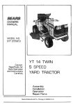
MODEL NO.
917.2546
Caution:
Read and Foflow
AH $Mety Rules
And instructions
Before Operating
This Equipment
TART
L T 12 PiP ELECTRIC
- 38"
LAWN TRACTOR
o
o
®
o
e
Assembly
Operation
Maintenance
Repair and Adjustment
Repair Parts
,,==,,j .........................
,,r
Sears,
Roebuck
and Co.,
Chicago,
IL
60684
U.S.A.
'
....
"' '"1 ........... I .........
I.
2.
3.
4.
5.
6.
7.
8.
9.
10.
11.
12.
Know the controls and how to stop quickly. READ THIS
OPERATOR'S MANUAL and instructionsFurnished with
attachments.
Do not allow children to operate the machine. Do not
allow adults to operate it Without proper instruction.
De not carP/passengers. Do not mow _,hee children and
others are around.
Alwaxs wear substantial footwear. Do not wear loose {it.
ring Elothing that could get caught in moving parts.
Keep your eyes and mind on xour tractor, mower and
the area bein_ cut. Do not let other interestsdistract ygu.
Do not attempt to operate your tractor or mower _,hee
not in the drivers seat.
Always get on or off your tractor from the operator's left
hand side.
Clear the work area of objects (wire, rocks, etc.) which
might be picked up and thrown.
Disengage all attachment dutches before attemp#ng to
start the engine.
Disengage power to attachments and stop the engine
before leaving the operator's position.
Disengage power to mower, stop the engine, and disconnect spa-rk plug wire(s) from spark plug(s) before clean:
ing, makin.g an adjustment, or repair, be careful to avoid
touching hot muttler or engine components.
Disengagepowertoa#achmentswhentransportingornot
Limit loads to those you can safety control.
Do not turn sharply. Use care when backing.
Use counterwgight or wheel weights when suggested
in the owneKs manual.
24. Watch out for traffic when crossing or near.roadways.
25. When using any. attachments, never direct discharge of
material towar_l bystanders nor allow anyone near the
vehicle while in operation.
26. Handle gasoline with care - it is highly Flammable.
a. Use approved g.asoline contaitiers.
b. Never remove Fhefuel cap of the fuel tank or add
gasoline to a running, or hot engine or an engine that
has not been allowe_l to cool for several minutes after
runnlna. Never fill tank indoors. Always clean up
sDilled'aasoline.
c. .Open doors if the engine is run in the garage - exhaust Fumesare dangerous. Do not run the engine
indoors.
27. Keep the vehicle and attachments in good operating con.
dition, and keep safety, devices in place and wo_ing.
28. Keep all nuts,,b'olts ancI screws tight to be sure the equTp.
ment is in safe working condition.
29. Never store the equipmeet with gasoline in the tank in.
side a building where fumes may reach an open flame
or spark. Alllow the engine to cool before storing in any
In
30.
b.
c.
d.
enclosure.
use.
13. Take all possible precautions when leaving the vehide
unatteeded. Di._ngage thepower.take-off,'7ower, the attachments, shift into neutral, set the parking bratce, stop
the engine and remove the key.
14. Do not stop or start suddenly when going uphill or
downhill, fAow up and down the face of slopes (nat
3 I.
32.
_rleater than 15°j; never across the face. Refer to page
15. Reduce speed on slopes and make turnsgradually to prevent tipping or loss of controL.Exercise extreme caution
when chen_glngdirection on slopes.
16. While going up or down slopes, place Gear Shift Control Lever m 7st gear positlon to negotiate the slope
without stopping.
17. Never mow m wet or slippery grass, when tr.action is unsure or at a speed whichcouFd cause a skid.
18. Stay alert for holes in the terrain and other hidden
hazards. Keep away from drop-arts.
19. Do not drive too dose to creeks, ditches and public
highways,
20. Exercise special care when mowing around fixed oblects
in order to prevent the blades from striking them. hfever
deliberately run tractor or mower into or over any foreign
objects,
21. Never shift gears until tractor comes to a stop.
22. Never place hands or feet under the mower, in discharge
chute or near any moving parts while tractor or mower
is running. Always keep clear of discharge chute,
23. Use care when pulling loads or using heavy equipment,
a. Use only approt;ed drawbar h#_chpolnts.
.....................................
To reduce fire hazard, keep the engine free of grass,
leaves or excessive grease. Do not c'/ean product while
engine _srunning.
Except for adjustments; DO NOT operate engine if air
cleaner or cover directly ever carburetor air intake is
removed. Removal of suchpart could create a fire hazard.
Donotoperatewithoutamufflerortamperwithexhaust
system. Damaged mufflers or spark arresters could create
a fire hazaid. Inspect periodically and replace if
necessary.
33.
34.
35.
36.
37.
38.
The vehfde and attachments should be stopped and in.
spected for damage after striking a foreign ob_ect and
the damage, should be repairedbefore
restar#ng and
operating the egulpment.
Do not change the engine governor settings or overspeed
.the..engine; sgvere 9ra.mage.or injury may result_ .
When using the vehicle with mower, proceea as tallows;
a. Mow only in daylight or in good artificial light.
b. Shut the engine off when unclogging chute.
c. Check the bTade mounting bolts-f_r proper tightness
at frequent intervals.
Do not operate the mower wlthout the deflector shield in
place.
Disengage power to mower before backing up. Do not
mow m reverse unless absolutely necessary and then onIv after careful observation of the entire area behind the
(newer.
Under normal usage the gross catcher bag material issub.
ject to deterioration andwear. It should-be checked freq.uently for bag replacement. Replacement bags should
De checked to ensure compliance with the original
manufacturer's recommendallons or specifications_
LOOK FOR THIS SYMBOL TO POINT OUT IMPORTANT SAFETY PRECAUTIONS.
IT MEANS--ATTENTION! BECOME ALERT! YOUR SAFETY IS iNVOLVED.
CAUTIONL .LOOK FOR THIS WORD TO POINT OUT IMPORTANT EQUIPMENT PRECAUT!ONS.
I
THIS
/_
]{
_
_
UNIT
IS EQUIPPED
WITH
AN INTERNAL
COMBUSTION
ENGINE
AND SHOULD
.........
NOT
BE USED
ON OR NEAR ANY UNIMPROVED
FOREST COVERED,
BRUSH COVERED, OR GRASS COVERED
LAND UNLESS THE ENGINE S EXHAUST
SYSTEM IS EQUIPPED WITH A SPARK ARRESTER MEETING APPLICABLE
LOCAL OR STATE LAWS (IF ANY). IF A SPARK ARRESTER IS USED, IT SHOULD
BE MAINTAINED
IN EFFECTIVE
WORKING
ORDER
BY THE OPERATOR.
In the State of California the above is required by law (Section 4442 of the California Public Resources Code). Other
states may have similar laws. Federal laws apply on federal lands. Refer to the Repair Parts Section, page 32.
H
CONGRATULATBONS
on your purchase
of a Sears
Lawn Tractor. It has been designed,
engineered
and
manufactured
to give you the best possible dependability and performance.
Should you experience
any problem you cannot easily; remedy, please contact your
nearest Sears Service Department.
We have competent, well-trained technicians
and the proper tools to
service or repair this unit.
DATE OF PURCHASE
THE SERIAL NUMBER WiLL BE FOUND ON
THE MODEL PLATE UNDER THE SEAT.
MAINTENANCE
AGREEMENT
A Sears Maintenance
Agreement
is available on this
product. See the nearest Sears store or service center
for details.
CUSTOMER
YOU SHOULD RECORD THESE NUMBERS
AND KEEP FOR FUTURE REFERENCE.
L.....
,,
RESPONSIBILITIES
Read and retain this manual. Study and observe the safety rules. Always use care when using your tractor.
Always keep your tractor and mower clean. Follow a regular schedule in maintaining, caring for, and using
your tractor. A well cared for tractor will run better and last longer.
ATTACHMENTS
This unit can use many attachments now available at your Sears store, it cannot use attachments that engage
the ground like a plow, harrow, cultivator, or tiller. See page 49 for a list of available attachments.
............................................................
u_ .........
LJ
.....................................................................................................................
LIMITED TWO YEAR WARRANTY
ON ELECTRIC START RiDiNG EQUIPMENT
For two years from date of purchase, when this riding equipment is maintained, lubricated, and tuned up according to the operating and maintenance instruction in the owner's manual, Sears will repair free of charge any
defect in material or workmanship in this electric start riding equipment.
This warranty excludes blade(s), blade adapter(s), spark plug(s) air cleaner and belt(s), which are expendable
and become worn during normal use.
This warranty does not cover:
Tire replacement
or repair caused by punctures from outside objects (such as nails, thorns, stumps,
or glass); and
repairs necessary because of operator abuse or negligence, including the failure to maintain the equipment according to instructions contained in the owner's manual; and
riding equipment
used for commercial
or rental purposes.
FULL 90-DAY
WARRANTY
ON BATTERY
For 90 days from the date of purchase, if any battery included with this riding equipment proves defective in
material or workmanship and our testing determines the battery will not hold a charge, Sears will replace the
battery at no charge,
WARRANTY SERVICE IS AVAILABLE BY CONTACTING THE NEAREST SEARS SERVICE CENTER/DEPARTMENT
IN THE UNITED STATES. This warranty applies only while this product is in use in the United States.
This warranty gives you specific legal rights, and you may also have other rights which may vary from state
to state.
SEARS,
ROEBUCK and CO.,
D/698-731A,
3
Sears Tower,
Chicago,
II 60684
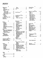
INDEX
A
Adjustments:
Brake ...................
Carburetor ...............
Mower Drive Belt .........
Mower
Front-to-Rear ...........
Side-to-Side ..........
Throttle Control Cable .....
Engine Valves ...........
Air Filter
Cleaning ................
Element ...............
Air Intake Screen, Eng ......
Assembly ................
Attachments ..............
14
18
22
22
22
18
18
16
16
16
5-8
50
B
Battery:
Charging .................
7
Cleaning ................
15
Installation
...............
8
Levels ..................
75
Preparation ...............
7
Starting with Weak Battery . 17
Storage .................
23
Terminals ...............
15
Belt:
Motion Drive Replacement .. 19
Mower Drive Adjustment ... 22
Mower Drive,
Remove/Replace ........
21
Blade:
Sharpening ..............
74
Replacement .............
14
Brake Adjustment ...........
14
C
Carburetor Adjustment .......
Controls, Tractor ............
Cutting Level, Mower ........
E
Engine:
Air Screen ...............
Oil Change ..............
Oil Level ................
Oil Type ................
Starting .................
Storage .................
Valve Adjustments ........
18
9
72
16
16
16
16
10
23
18
F
Filter:
Air ............................................ 16
Fuel .......................................... 18
Fuel;
Type ...................
10
Storage .................
23
Type ...................
Storage .................
Fuse .....................
H
Hood Removal .............
L
Levelling Mower Deck .......
Lubrication:
Chart ...................
Tractor Pivot Points .......
10
23
20
20
22
24
17
M
Maintenance ...............
13
Air Filter ................
16
Air Filter Element .........
16
Air Screen ...............
16
Battery .................
15
Blade Sharpening .........
14
Brake Adjustment .........
14
Engine Oil ...............
16
Fuel Filter ...............
18
Lubrication Chart .........
24
Spark Plug ..............
18
Tire Care ................
14
Mower:
Adjustment, Front-to-Rear
. . 23
Adjustment, Side-to-Side . , . 22
Blade Sharpening .........
14
Blade Replacement ........
14
Cutting Level ...........
12
Installation
..............
21
Operation ...............
11
Removal ................
20
Muffler ...................
17
Spark Arrester .............
2
0
Oil:
Cold Weather Conditions . . . 16
Engine ..................
16
Storage .................
23
Operation ...............
9-12
Operating Your Mower .....
11
Operating Your Tractor .....
11
Starting the Engine ........
!1
Stopping Your Tractor .....
!0
Tractor Operation on Hills... 12
Options:
Attachments .............
50
Spark Arrester .............
2
P
Parking Brake ................
Parts Bag ..................
9
5-6
R
Repair and Adjustments ....
Blade .....................
Carburetor ................
Fuse .....................
Hood Removal ............
Motion Drive Belt
Replacement ..............
Mower Drive Belt
Replacement .............
Mower Adjustment
Side-to-Side ..............
Mower Removal ...........
14-24
15
18
.20
20
70
20
Z2
20
S
Safety Rules ................
Seat .......................
Service Record ..............
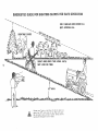
Slope Guide Sheet ...........
Spark Plug .................
Speed Control Chart ..........
Starting the Engine ...........
Steering Wheel ...............
Stopping the Tractor .........
Storage ....................
2
7
13
51
18
12
11
5
10
23
T
Throttle Control Cable
Adjustment ................
Tires ......................
Trouble Shooting Chart
!8
14
25
.......
V
Valves Adjustments ..........
18
W
Warranty ....................
Wiring (Schematic) ...........
3
27
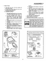
ASSEMBLY
7.
Unpack
Tractor
a.
Take items out of box. The box contains the
items shown below.
b. Cut down four corners of the carton with a utility knife and fold down sides.
c. Disengage Parking Brake.
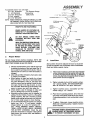
d. Instafl Steering Wheel
7.
2.
3.
4.
5.
6.
7.
Slide upper steering shaft over lower steering shaft until bolt holes fine up with slots
in lower
steering
shaft
(Fig.
7).
Use two hex bolts 3/8 - 76 x I- 7/4 and two
Iocknuts 3/8 - 76 to reta'in upper steering
shaft to lower steering shaft. Tighten
securely. Bolts and nuts found in bag of
parts.
Position Steering Sleeve over steering shaft
assembly.
For easier assembly, tilt tube towards front
of tractor.
Place bottom of Steering Sleeve over two
front prongs on steering bushing.
Squeeze the two steering sleeve retainers inward to allow Steering Sleeve to pass over
retainers.
Push Steering Sleeve down aligning notch on
Steering Sleeve with tab on steering
iii
bushing.
8, Place steering wheel adapter on upper steering shaft.
9. With front wheels pointed straight ahead,
place steering wheel on steering wheel
adapter. Bars of steering wheel should point
straight across tractor.
10. Place 2 _ t/4"" diameter washer on upper
steering shaft and instafl a 7/2" Iocknut
{washer and tocknut found in bag of parts).
Tighten securely.
t 1. Snap insert into steering wheel.
e. Remove plastic on tractor hood.
f. Raise attachment lift handle.
g. Roll Tractor off skid. Be careful of staples in skid.
The operation of any tractor can result in
foreign objects thrown into the eyes,
which can result in severe eye damage.
Always
wear safety
glasses or eye
shields before starting your tractor and;
while moving.
We recommend
Wide
Vision Safety Mask for over the spectacles or standard safety glasses, available at Sears Retail or Catalog Stores.
......
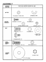
Parts Bag Contents
Not Shown
Full Size:
iiiii
_I
0
,i
IIIIlIIIIIII[IIIIIIIIIIIIIIIIIIIIFIIIIIIIIIIIIIIIII
(2) Battery Carriage Bolts - 114-20 x 7-I/2
Terminal Guard
A
G
15 ° Slope Instruction
H
(2) Keys
@
F
a.
b.
c.
d.
seat
Steering wheel
battery
battery acid
e. owner's manual
f. parts bag
steering sleeve
_i upper steering shaft
ring Wheel
Battery
Caps
And Instructions
Adapter
Steering
Wheel
Insert
ASSEMBL
(
ASSEMBL Y
LOCATION
PANTS BAG CONTENTS
SHOWN
FULL SiZE
BATTERY
(2) Lockwasher,
1/4 Int/Ext
(2) Wing Nut, 1/4-20
Tooth
©
BA TTERY
TERMINALS
12) Hex Bolt,
1/4 - 20
x 3/4
(2) Lockwasher
©_)
(21 Washer
i1=
9/32
x 5/8
x 16 Ga.
1.1.1.1.1.11.
i
i _111 i
©
1/4
(2/Hex
Nut,
1/4 - 20
i
SEA T
,j
(11 Hex Bolt,
I/2
- 13 - x 1
(1) Loci(washer
1/2
{1)
(1) Shoulder
bolt
5/16
Washer 17/32 x 1 3/16 x 12 Ga.
- 18
ii
i.=.
m.,.,.,H
= HH'--I
_11I '1_
C_I
UPPER
STEERING
SHAFT
12) Hex
Bolt 3/8
_ 16 x I
1/4
(2) Hox Locknut
3/8
- 16
STEERING
WHEEL
(1) Locknut,
114"
6
Dia.
Washer
1/2-20
Y
To assemble tractor you will need:
(2) 7/t6"
Wrenches
Tire Pressure Gauge
(t) 1/2" Wrenches
Screwdriver
(2) 9/16" Wrenches
Utility Knife
(1) 3/4" Wrench
(2) 11/16" Wrenches
NOTE: RIGHT HAND (R.H.) AND LEFT HAND (LH.) ARE
DETERMINED FROM OPERA TOR'S POSITION
WHILE SEA TED ON THE TRACTOR.
......i
,
i]
STEERING
STEERING
,111,,111,,i,1,1,
i
UPPER ADAPTER
STEERING
SHAFT
WEAR EYE AND FACE SHIELD.
WASH HANDS OR CLOTHING IMMEDIA TELY IF ACCIDENTALL Y IN
CONTACT WITH BATTERY ACID.
WHEEL
WHEEL_
----_..._
TUBE
BOLTS
DO NOT SMOKE: FUMES FROM
CHARGED
BATTERY ACID ARE
EXPLOSIVE.
FIGURE
2.
Prepare
1
JUTS
READ THE INSTRUCTIONS INCLUDED WITH THE BATTERY VENT CAPS
IN THE BAG OF PARTS. ALWAYS
WEAR GLOVES, CLOTHING AND
GOGGLES TO PROTECT
YOUR
HANDS, SKIN AND EYES.
fl,,,,,, ,i
-- .",,
ER_NG
SHAFT
STEERING
SLEEVE
RETAINER
SPRING
",
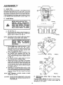
Battery
Fill and charge battery (before installing), NOTE: SEE
DETAILED INSTRUCTIONS PACKAGED WITH BATTERY
VENT CAPS FOUND IN BAG OF PARTS.
a. Fill each cell with battery acid. Add the acid until
it reaches the bottom of the vent tubes (Fig. 3).
Do not add the acid beyond this level or the additional acid can come out when the battery is
charged.
b. After cells are filled, tilt battery from side to side
to release air bubbles.
c. Allow battery to stand and settle for at least
thirty minutes. If the level of acid falls below
the point described in step (a), add more acid
until the correct level is reached. Install the battery caps, found in the bag of parts, to cover
the vent tubes. Wash the top of the battery with
water to remove any acid, then wipe dry.
d. Check battery case for leakage to make sure
that no damage has occured in handling.
e. Neutralize excess battery acid for disposal by
adding it to four inches of water in a five gallon
plastic container. Stir with a wooden or plastic
paddle while adding baking soda until the addition of more soda causes no more foaming.
f. It is recommended that the battery be charged
before use. Use a 12 volt battery charger.
Charge battery at a rate of 6 amperes for 1
hour. NOTE: OBSERVE SAFETY PRECAUTIONS, LISTED IN BOX ABOVE, REQUIRED
FOR BATTERY CHARGING. Check the acid
level after the battery is charged, ff the acid has
fallen below the correct level, add distilled or
iron free water."
SLEEVE
RETAINER
SPRtNG
3.
Install Seat.
Seat position should be adjusted forward or backward
so that the operator can comfortably reach Clutch/Brake
Pedal and safely operate tractor.
a.
Place seat on seat pan. Screw hex head machine
screw, lockwasher and flat washer into seat (Fig.
2). Screw shouider bolt into seat (Fig. 2). Machine
screw, shoulder bolt and washers found in bag of
parts (shown full size on page 6).
b. Tighten shoulder bolt and flat washer using a
1/2"" wrench, NOTE: THE SHOULDER BOLT
WILL BE LOOSE IN THE SEAT PAN SLOT.
c. Tighten machine screw, Iockwasher and flat
washer using a I/2" wrench.
d*
Place seat in operating position. Sit on the seat
and press clutch/brake pedal all the way down.
If operating position is not comfortable, adjust
seat.
e.
To adjust: Raise seat. Loosen machine screw.
Slide seat to desired position. Tighten machine
screw securely.
WASHER MUST BE TUGHTENED SECURE-
A$SEMBL Y
_fAT
4. Check Tires
Check the air pressure in the tires. Tires with too much
air pressure will cause the unit to ride rough. The wrong
air pressure will also keep the mower from cutting level.
The correct air pressure is shown on the side of the tires.
If the air pressure is not shown, set to pressures shown
in the REPAIR AND ADJUSTMENT section (page 14).
J
PA_
__
BOLT _
SlAT
_.o_
#_Dln
Instal} Battery
.
Wltt
, i1,,,
OATfI_Y
BEFORE INSTALLING BATTERY,
REMOVE
METAL
BRACELETS,
(*_£T
AWAY
VH:W
FIGURE 2
I_ATTERY
CAP
FROM
YOUR PERSON.
TOUCHING
WRISTWATCH
BANDS, RINGS,
ETC.
THESE ITEMS TO BATTERY TERMINALS COULD RESULT IN BURNS.
L,-.--.-J
TUDE
a. Lift seat (Fig. 2).
b. Lower battery into fender weft with battery terminals toward front of tractor (Fig. 4). Make sure
battery rests in battery tray (Fig. 4).
.BATTERY
CELL FIGURE 3
NOTE: BE SURE BATTERY DRAIN TUBE IS SECURELY
ATTACHED TO BATTERY TRAY DRAIN.
i ,11,1
iiii Ull,lrl,ii,_1,1
u,1111
ilU,
POSITIVE TERMINAL MUST BE CONNECTED
FIRST
TO PREVENT
SPARKS
FROM
ACCIDENTAL
GROUNDING.
WASHER
POSiTiVE
TERMINA
/
POS_T;VE
CABLE
tRED_
\
i
c. Connect RED battery cable to positive (+) battery terminal with hex bolt, flat washer,
Iockwasher and hex nut (shown full size on pg.
6) found in bag of parts. Tighten securely with
two 7/16" wrenches. (Fig. 4)
d. Connect BLACK ground cable to negative (-) battery terminal with remaining hex bolt, flat
washer, Iockwasher and hex nut (shown full size
on pg. 61 found in bag of parts. Tighten securely. (Fig. 4)
e. To prevent corrosion, apply grease to the battery terminals after installing cables.
f. Using the key hole on one side of the battery
support (Fig. 5) slide battery bott into frame key
hole (head of bolt down). Fasten the battery bolt
to the terminal guard using internal/external
Iockwasher, wing nut, (shown full size on pg. 6)
as shown in Fig. 5.
g. Assemble the remaining battery bolt to other
side of battery support and fasten terminal guard
to it with remaining internal/external Iockwasher,
wing nut, (shown full size on pg. 6) as shown
in Fig. 5.
NOTE: KEEP TERMINAL ACCESS DOORS CLOSED
WHEN NOT IN USE.
CAUTION:
DO NOT START ENGINE UNTIL YOU HAVE
REVIEWED THE OPERATION SECTION OF
THIS MANUAL.
BATTERYTRAY
FIGURE 4
BATTERY
BOLT
\
KEY
HOLE
6.
FIGURE 5
Maintenance
After
First 2 Hours
(Two
Mowings)
Changing oil after thBJ_rsttwo hours (or two mowings)
wilt help eliminate break-in residue which might be
oFamagingto your engine.
OPERA ON
KNOW YOUR TRACTOR
RF_AD THiS OWNER'8 MANUAL OEFORE OFERA TING YOUR LAWN TRACTOR. ff you understand
the unit and its operation, you will achieve efficient and peak performance.
While reading the manual, compare the illustrations with your
Lawn Tractor to familiarize yourself with the location of various controls and adjustments. Study the operating instructions and safety precautions thoroughly to insure proper functioning of your Lawn Tractor and to prevent injury to yourself
and others. Be sure to pay strict attention to aft warnings and cautions: they are included for your safety. Save this
manual for future reference.
Light Switch
Attachment
Lift Lever
Clutch/Brake
Pedal
Clutch
Lever
Height
Adjustment
Knob
_,_
Parking Brake
Gear Shift Lever
GEARSHIFT'. Press the clutch/brake pedal down firmly
and move gear shift lever to desired speed.
ATTACHMENT CLUTCH LEVER: Push lever up to engage
attachment. There wil! be an engine hesitation as the
clutch engages.
IGNITION: Place key in ignition and turn to the right to
start. The switch spring returns from the start positon.
ATTAC_NT
L_cT LEVER: Use the attachment lift lever
to raise and lower the attachment mounted to your tractor. Pull lever back slightly and push button, then move
the lift lever forward to lower attachment.
L_HT
SWITCH:
Turns the headlights on and off.
PARKING BRAKE: To set the parking brake, push the
clutch/brake pedal completely down. Hold the parking
brake lever in "'Engage" position and release pressure
from pedal. Clutch/brake pedal will remain in brake
position.
CLUTCH/BRAKE _DAL:
The pedal has 2 functions; a
clutch and a brake. To engage the brake push the pedal
completely down.
A TTACHMENT HEIGHT ADJUSTMENT KNOB: Use the
height adjustment knob to adjust the mower height. With
the attachment lift lever in the "up'" position, turn knob
clockwise
(f'_J
to raise cutting
height and
counterclockwise (/'_,) to lower cutting height.
_TTLE/CHOKE
COtJTROL: Use the throttle control
to increase or decrease the speed of the engine, and to
choke the engine for starting. Push lever to the right and
forward to choke.
g
OPERA TION
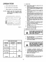
7.
Stopping
NOTE: REMOVE KEY WHEN LEAVING
TO PREVENT UNAUTHORIZED
USE.
AIR
SCREEN
a.
b.
c.
\
d
FUEL
CAP
FILLER
e.
TANK
f.
/
FIGURE
2.
/
6
Your Tractor
TRACTOR
Push clutch-brake
pedal into full "'BRAKE'"
position. Keep your foot on pedal. (Fig.7)
Place
attachment
clutch
lever
in
"'DISENGAGED"
position. (Fig;7)
,,
Move gear shift lever to
NEUTRAL
postion. ('Fig7)
Place pePklng brake in "'ENGAGED"
position and release pressure from clutch/brake.
Pedal should remain in "'BRAKE" position.
(Fig.7)
Move
throttle
control
to "'S" (slow)
position. (Fig.7)
,,
Turn i nition key to OFF" position.
use cr_nke to stop engine. (Fig.7)
Never
Preparing
The Engine
........
I
LEARN TO START, STOP AND REVERSE YOUR TRACTOR IN A LARGE,
OPEN AREA.
,,i
a.
b.
..........
This engine has been shipped filled with summer weight oil (For cold weather operation see
chart page 16). Check engine oil level. Refer to
REPAIR AND ADJUSTMENT section (page 16).
Fill fuel tank (Fig. 6). Use fresh, clean, regular
unleaded gasoline. Capacity is 5 quarts.
i,i1,1,1111,,11
,111
FILL TO BOTTOM OF GAS TANK
FILLER NECK. DO NOT OVERFILL.
WiPE OFF ANY SPILLED OiL OR
FUEL. DO NOT STORE, SPILL OR USE
GASOLINE NEAR AN OPEN FLAME.
I
CAUTION:
MOWER
BLADE
CLUTCH
POSITION
"ENGAGED".
"OISENGAGEO"
POSITION
HEADLIGHT
EXPERIENCE INDICATES THAT ALCOHOL
BLENDED FUELS (CALLED GASOHOL OR
USING ETHANOL OR METHANOL) CAN ATTRACT MOISTURE WHICH LEADS TO
SEPARATION AND FORMATION OF ACIDS
DURING STORAGE. ACIDIC GAS CAN
DAMAGE THE FUEL SYSTEM OF AN
ENGINE WHILE IN STORAGE .....
TO AVOID ENGINE PROBLEMS, THE FUEL
SYSTEM SHOULD BE EMPTIED BEFORE
STORAGE FOR 30 DAYS OR LONGER.
DRAIN THE GAS TANK, START THE
ENGINE AND LET IT RUN UNTIL THE FUEL
LINES AND CARBURETOR ARE EMPTY.
USE FRESH FUEL NEXT SEASON. SEE
STORAGE INSTRUCTIONS
FOR ADDITIONAL INFORMATION.
"DISENGAGED"
POSITION
"CLUTCH'*
POSITION
/
GEARSHIFT
LEVER
NEVER USE ENGINE OR CARBURETOR
CLEANER PRODUCTS IN THE FUEL TANK
OR PERMANENT DAMAGE MAY OCCUR.
FIGURE
7
10
Starting
3_
a.
b,
Move throttle control lever (Fig, 7)past "'FAST"
to the "CHOKE" position.
Turn ignition key to "'START" and release key
as soon as engine starts,
CAUTION:
c.
d.
e.
OPERA TION
The Engine
ATTACHMENT
CLUTCH
LEVER "DISENGAGED"
POSITION
ATTACHMENT
CLUTCH
LEVER "'ENGAGED"
POSITION
HEIGHT
ADJUSTMENT
KNOB
LiFT LEVER
PLUNGER
DO NOT RUN STARTER CONTINUOUSLY
FOR MORE THAN FIFTEEN SECONDS PER
MINUTE.
LIFT LEVER
• "HIGHEST"
OStTION
LIFT LEVER
If engine does not start after four or five tries,
move throttle control lever to "FAST"
position,
wait a few minutes and try again. If the engine
does not start after four or five more tries, see
the TROUBLESHOOTING
Chart (page 25).
After
the engine starts move throttle
control
lever slowly
to the "SLOW"
position.
To start a hot engine move the throttle control
lever to a position
between
"'FAST"
and
"SLOW".
POSITION
RUNNER
READ
THE,,
OPERATION
"RULES
FOR SAFE
CAREFULLY
BEFORE
RGE
GUARD
TiNG YOUR MOWER.
CAUTION:
i
DO NOT ADD ADDITIONAL WEIGHT TO
THE TRACTOR OTHER THAN THE OPTIONAL WHEEL WEIGHTS. EXCESSIVE
WEIGHT MAY OVERLOAD AND DAMAGE
THE TRANSAXLE.
FIGURE 8
4.
, ii
Operating
Your Lawn Tractor & Mower
ALWAYS WEAR SUBSTANTIAL FOOT-
DO NOT OPERATE THE MOWER WITH-
WEAR ANDTHAT
AVOID
LOOSE
FITTING
CLOTHING
COULD
GET CAUGHT
iN MOVING PARTS.
OUT
EITHER
THE ENTIRE
GRASS
CATCHER,
ON MOWERS
SO EQUIPPED,
OR THE DEFLECTOR SHIELD IN PLACE
t,t, t,tt tt,,
NOTE: THIS TRACTOR IS EQUIPPED WITH AN
OPERATOR PRESENCE SENSING SWITCH. ANY
ATTEMPT BY THE OPERATOR TO LEAVE THE
SEAT WITH THE ENGINE RUNNING AND THE
ATTACHMENT
CLUTCH LEVER ENGAGED
WILL SHUT OFF THE ENGINE,
CAUTION
TO AVOID INJURY
I. Read owner's manual,
2. Know location and function of all controls.
3. Keep guards, safety shield and switches in place
and working.
4, Remove objects that can be thrown by blades,
5. Do not mow when children and others are around.
6. Never carry children or passengers.
7. Always took behind machine before backing.
8. Do not mow where machine can tip or slip.
9, If machine stops going uphill, stop blades and back
slowly down.
10, Be sure blades and engine have stopped before placing hands or feet near the blades.
t 1, Remove key when leaving machine.
a . Move the attachment lift lever to the high position and adjust height of cut to mid range. See
Fig. 8.
b. Start the engine.
(See Starting
the Engine)
c. Move the throttle lever to mid range position.
Select a tow (1st or 2nd) gear until you become
more familiar with the operation of the unit.
d, Slowly release clutch brake pedal and proceed
to the mowing area.
MAKE SURE PARKH_G BRAKE WeLL HOLD
TRACTOR SECURe.
e. Stop the unit, then select a mowing speed. (See
Speed Selection Guide, page 12).
NEVER PLACE YOUR HANDS OR FEET iN
f. Move throttle lever to half throttle and slowly
move attachment clutch lever to engaged position, Fig. 8.
_NT UND_ER
OR
OR _.AR
ANY ANY
POWERED
_V6_ ATTACHPART
WH_LE TRACTOR OR ANY POWERED
ATTACHMENT iS RUNN_G.
11
OPERA TION
g.
Slowly
release
h,
Move
i.
Observe
throttle
height
5.
clutch brake
NOTE:
pedal.
a.
lever to fast position.
of cut and readjust
Mowing Tips
as desired,
b.
CAUTION:
BEFORE YOU MOVE
THE GEAR SHIFT
LEVER, COME TO A COMPLETE
STOP.
FAILURE TO DO SO CAN RESULT IN GEAR
BOX DAMAGE.
c.
f
d.
T
e.
f .
FIGURE
g.
h.
9
6.
TIRE CHAINS CANNOT'BE
USED WITH THE
MOWER ATTACHED.
Mower should be adjusted properly front to back
and side to side for good mowing performance.
Refer to REPAIR AND ADJUSTMENT
section
(page 22).
Use the runner on the R.H. side as a guide; the
blade cuts approximately
an inch outside
the
runner (Fig. 8).
Drive so that clippings are discharged
onto the
area that has been cut. Have the cut area to the
right of the machine.
This will result in a more
even distribution
of clippings and more uniform
cutting.
When mowing large areas (Fig. 9), start by turning to the right
so that the clippings
will
discharge away from shrubs, fences, driveways,
etc. After two or three rounds, mow in the opposite direction
making left hand turns until
finished.
If grass is extremely
taft, it should be mowed
twice. The first time cut relatively
high; the second time to the desired height.
The left hand side of mower should be used for
trimming.
See Speed Selection
Chart.
Do not mow tall, dry (brown) grass over 6 inches tall. It is a fire hazard.
Operating
The Tractor
On Hills
DO NOT DRIVE UP OR DOWN HILLS
WITH SLOPES GREATER THAN 15 °
AND DO NOT DRIVE ACROSS ANY
SLOPE. REFER TO PAGE 51.
a .
b.
c.
SPEED SELECTION
i
GUIDE
,,i,
FUNCTION
I,IIM,II,
GEARSHIFT
i,11,, ,111,,111,1,,
i
THROTTLE
.... iii1,1,1
....
ii
._
2or3
Normal
Mowing
Move gear shift lever to "" I st'" gear before starting up or down hills.
AVOID STOPPING OR SHIFTING
ON HILLS.
If slowing is necessary, move throttle
control
lever to slower position.
LEAVE ENOUGH ROOM WHEN STOPPiNG AND STARTING
TO ALLOW
SLIGHT TRACTOR
ROLL DOWNHILL
AS CLUTCH-BRAKE
PEDAL MOVES
THROUGH
CLUTCH POSITION.
iii
Heavy
Mowing
U
!
q
I or2
d.
Snow
1
Blowing
If stopping is absolutely necessary, push
clutch/brake pedal quickly to brake position.
e . To restart tractor movement, make sure tractor
is in the lowest speed range ("1st'" Gear) and
release clutch-brake pedal SLOWLY.
f. Make all turns gradually.
FAST
i
Snow
2
Blade
' i ,"'m','m';
Transport
4-6
7.
SLOWFAST
Transporting
Your Tractor
For pushing or towing your tractor, place Gear Shift Lever in
"N" position. Do not tow or push at more than 6 MPH.
12
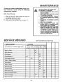
MAINTENANCE
To keep your tractor running better, longer, perform necessary
service
using the following
maintenance
schedule:
With
I.
Every
BEFORE MAKING ANY iNSPECTiON,
ADJUSTMENT, OR REPAIR:
1. PUSH CLUTCH/BRAKE PEDAL COMPLETELY DOWN.
2. MOVE GEAR SHIFT CONTROL LEVER
TO NEUTRAL POSITION.
3. PLACE PARKING BRAKE IN "ENGAGED" POSITION. REMOVE FOOT FROM
PEDAL.
4. DISENGAGE ATTACHMENT CLUTCH
LEVER.
5. SHUT OFF THE ENGINE.
6. MAKE ABSOLUTELY
SURE THE
BLADES AND ALL MOVING PARTS
HAVE COMPLETELY STOPPED.
7. DISCONNECT THE SPARK PLUG WIRE
FROM THE SPARK PLUG AND KEEP
WIRE AWAY FROM THE SPARK PLUG
TO PREVENT INJURY FROM ACCIDENTAL STARTING. BE CAREFUL TO
AVOID TOUCHING HOT ENGINE OR
MUFFLER COMPONENTS.
Mewing
Make sure all nuts on bolts are tight and cotter pins
and retainer springs are secure,
Observe all safety precautions,
Keep tractor
well lubricated
(refer to page 17).
2.
3.
SERVICE
RECORD
(Enter Date Maintenance Performed)
SERVICE RECORD
Fill in dates
as you complete
SCHEDULE
regular
service
FIRST
EVERY
EVERY
EVERY
EVERY
2
HOURS
5
HOURS
25
HOURS
50
HOURS
!00
HOUR_
Blades- sharpen
Brake Adjustment
Check Battery
i
Change Engine Oil
_r
t,j
i
i
Check EngineOil Level
_'
,,i
Clean
Air C{eaner
,,
Element
_,_
,11i1,, i
Check Muffler
i.........
'
Clean Air Screen
Clear_Front Grill
,i,i,,,
LubricateTractor
_'_
i
ReplaceSpark Plug
_'
'
Replace
Check
Air Cleaner
Tire
,i
...........
Element
Pressure
_==
,LL
Replace Fue! Filter
.......,,,,,_,,,,,,,,,,,,,
,,
............
13
.........
,,
i
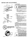
AND ADJUSTMENT
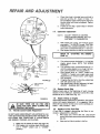
1. Brake Adjustment
This tractor is equipped with an adjustable brake system
mounted on the right side of the transaxle (Fig. I0).
BRAKE
.r.r,,.
ROD
IFTRACTOR
j_
|WITH PARKING
BRAKE ENGAGED)
BRAKE
FIGURE
10
BL
WASHIER
L_KWASHER
FIGURE
BOLT
SIX
FEET GEAR,
STOPPING
HIGHEST
THEN DISTANCE
BRAKE MUSTIN
BE ADJUSTED.
Road test tractor
for proper stopping
stated above. Readjust if necessary.
w
HEX
_:_
MORE THAN
a . Depress clutch/brake pedal and engage parking
brake.
b. Measure distance between brake operating arm
and nut "'A'" on brake rod.
c, If distance is other than I- 1/2"', loosen jam "'A ""
nut (Fig. t0) and turn nut until distance becomes
1-I/2", Retightenjam nut against nut "'A".
1 • I/2"'
DISC
.............
REQUIRES
GR, 5_
11
)
A GRADE 5 HEAT TREATED BOLT
CAN BE IDENTIFIED
BY THREE
LINES ON THE BOLT HEAD AS
SHOWN AT LEFT.
distance
as
Tire Care
a, Maintain tire pressure in front at 14 PSi and rear
tires at 12 PSI.
b . Keep tires free of gasoline, oil, or insect control
chemicals which can harm rubber.
c, Avoid stumps,
stones, deep ruts and other
hazards that may cause tire damage.
d. Removing wheel for tire repair (Fig, 12).
1 - Block up axle securely.
2 - Remove hub cap, klip ring and washer to
allow wheel removal.
3 - Repair tire and reassemble. Replace washers
and snap klip ring securely in axle groove.
Replace hub cap.
3.
Blade Care
For best results mower blades must be kept sharp. The
blades can be sharpened with a few strokes of a file, or
on a grinding wheel We suggest they be sharpened after
every 25 hours of mowing. Do not attempt to sharpen
while on mower. If you mow in sandy soil check the
blades after each two mowings.
The sand wears the
blade away rapidly.
a. Blade Replacement
Raise mower to highest position to permit access
to blades.
1. Remove the hex head bolt, Iockwasher
and
flat washer
(Fig. t 1) (turn counterclockwise) (f'_).
2.
Remove and discard old blade.
3.
Clean top and bottom of mower housing,
4.
Install new blade with SHARP EDGE DOWN
and secure with flat washer,
tockwasher
and hex head bolt, TIGHTEN SECURELY,
WASHERS
HUB
ALWAYS USE GRADE 5 HEAT TREAT- i
ED BOLTS TO ATTACH BLADES. DO
NOT USE PLATED BOLTS. CHECK _
BOLTS IN BLADES OCCASIONALLY
TO MAKE SURE BOLTS ARE TIGHT.
TORQUE BOLTS TO 30-35 FT.-LBS, J
CAP
KLIP
FIGURE
12
RING
14
REPAIR AND ADJUSTMENT
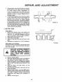
b.
C.
When grinding, care should be taken to maintain
blade balance and the blade should be checked
for proper
balance
before
reinstallation
on
mower. An unbalanced or bent blade will cause
excessive
vibration when running, and eventual
damage
to mower
or engine. Replace bent or
damaged blades.
To check blade balance, drive a nail into a beam
or walt. Leave about one inch of the straight nail
exposed. Place center hole of clean blade over
the head of the nail (Fig. 13), NOTE: CENTER
HOLE OF BLADE ON NAIL, IF BLADE IS PROPERLY BALANCED,
BLADE SHOULD REMAIN
IN
POSITION SHOWN IN FIG. 13. IF EITHER END
OF THE BLADE MOVES DOWNWARD,
BLADE
IS NOT BALANCED.
SHARPEN THE HEAVY END
UNTIL BLADE IS BALANCED.
4. BATTERY
HOLE
0 -
lll , j !l!
FIGURE
13
CARE
CIJ!
VI(W
DATTI[RY
IATTERY
""
_
•
I
VENT
TU_E
FtGURE14
Clean Battery and Terminals
Corrosion and dirt on the battery and terminals cause
the battery to "leak'" power and hinders the operation of the charger.
LEAD-ACID
EXPLOSIVE
AWAY
CAP
Check Battery
a.
Battery acid solution
level in each battery
cell
should be even with bottoms of vent tubes in
cells (Fig, 14), Add ONLY distilled or iron free
water if necessary.
NOTE: DO NOT OVERFILL.
b.
Keep battery and terminals
clean.
c. Keep battery bolts tight.
d. Keep vent caps tight and small vent holes in caps
open,
e.
Recharge at 6 amperes for 1 hour if necessary.
BATTERIES GENERATE
GASES. KEEP SPARKS,
FLAME FROM
AND SMOKING
MATERIALS
AWAY
BATTERIES.
ALWAYS
SHIELD
YOUR
EYES
AROUND
BATTERIES.
, ,,,, ,,,,,,,,,
a.
b.
Remove terminal guard.
Disconnect BLACK battery cable, then RED battery cable, and remove battery from tractor.
c. Wash battery with four tablespoons of baking
soda to one gallon of water. NOTE: BE CAREFUL
NOT TO GET THE SODA SOLUTION INTO THE
CELLS.
d. Rinse the battery with plain water, dry and
reinstafl on tractor.
e . Clean terminals and battery cable ends with wire
brush until bright.
f . Replace battery cables, connecting RED battery
cable to positive terminal first, then BLACK battery cable to negative terminal. Coat terminal
connections with grease after installation of
cables.
g. Replace terminal guard.
15
REPAIR AND ADJUSTMENT
.20
°
0 o
60 °
32 c
80 °
100 °
,! n l i !3Ho-!
30or 70W-
5W-30
UIil
6.
FUEL _\_\
CAP
Check Engine Off Level
NOTE:
Several minutes after stopping engine, check engine off
level with tractor on level ground. Wipe dipstick (Fig. 15)
clean, screw it down tight for a few seconds, remove
and read oil level. If necessary,
add oil until "'FULL'" mark
is reached.
(See chart
above).
NOTE:
DO NOT
OVERFILL.
FUEL
TANK
FIGURE15
ENGINE 01L
FILLER CAP
AND DIPSTICK
AIR CLEANER I
COVER
DO NOT CHECK ENGINE OIL LEVEL WITH
ENGINE RUNNING.
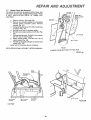
7.
-
Clean Air Cleaner Element
a.
Remove
two
cover
knobs
{Fig. 16)
and
remove
air cleaner
cover.
\,
b. Remove foam pre-c/eaner.
- - Wash pre-cleaner
in liquid
to remove
dirt.
-- Wrap pre-cleaner
in cloth
\
-=
AIR
SCREEN
FOAM
ELEMENT
detergent
and warm
and squeeze
water
dry.
e.
Wipe foam with a light coat of engine oil. Do not
saturate,
squeeze in rag or towel to remove excess oil.
Remove
two nuts from top of cartridge.
Remove cartridge
and clean air cleaner body carefully
to prevent
dirt from entering
carburetor.
Clean cartridge
by gently tapping
on flat surface.
If
f,
very dirty,
Reassemble
c,
d.
replace cartridge.
air cleaner,
NOTE:
Nuts holding air cleaner cartridge must be installed with
fiber washers
down on cartridge
plate to prevent dirt from
entering
carburetor,
Tighten
nuts by hand. Over tightening
could collapse cartridge,
NOTE:
NEVER RUN ENGINE
AIR
CLEANER
BODY
FIGURE
8.
AIR CLEANER
REMOVED,
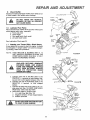
Clean Air Screen and Engine Cooling Fins.
i
i,i,
i
18
i,,
J_'
ALWAYS WEAR EYE AND FACE
PROTECTION WHEN USING COMJ
PRESSED AIR.
J
5.
Change
Engine Oil
The best time to change engine oil is at the end of a day's
operation when all dirt and foreign materials are suspended in the hot off.
Capacity is 1-1/2 quarts. NOTE: DO NOT OVERFILL.
Dipstick assembly must be securely tightened into tube
at all times when engine is operating.
IMPORTANT:
WlTH
i, i,ii ii, ,11,1,11
ii,
I
Air screen and cooling fins (Figs. 16 and 17) must be
kept
free of dirt and chaff
overheating.
to remove
Clean
dirt
and
with
dried
to prevent
engine
a wire brush
gum
damage
or compressed
from
air
fibers.
a. Remove hood (page 20).
b . Remove aircieanercover
(Fig. t6),
c, Remove 3 screws securing air cleaner body (Figs. 16
and 1 7) and remove,
(Cover carburetor
to prevent
entry of dirt.)
d. Remove off dipstick
and cover opening to prevent
entry of dirt.
e. Remove 3 screws from blower housing and lift housing off engine (Fig. 1 7).
f , Use compressed
air or stiff bristle brush to thoroughly
clean engine cooling fins (Fig, 1 7) and air screen (Fig.
16),
g. To reassemble,
reverse
above procedure.
h, Be certain carburetor
tube, breather tube, and gaskets
are in place (Fig. 1 7),
TO AVOID DAMAGE TO THE STARTING SYSTEM, USE SAE 5W30 OIL
WHEN THE TEMPERATURE FALLS
BELOW 32 ° .
Recommended SAE Viscosity Grades
Determine temperature range expected before next oil
change, All oil must meet A.P.I. service classification SD,
SE or SF.
16
FtEPAIFt
ADJUSTMENT
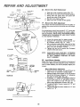
9. Check Muffler
Inspect and replace damaged muffler and/or deflector as
it could create a fire hazard and/or damage,
AIR
COVER
DO NOT TOUCH HOT MUFFLER,
CYLINDER OR FINS AS CONTACT
I.....
........................
!
MAY CAUSE BURNS.
=
i,,i,
,i
..
See Lubrication
Chart
SCREWS
,
10.
Lubricate
Pivot Points
Place several drops of SAE 30 off at points where parts
move against each other, expecially:
a. Front axle pivot
b. Hood hinges
c. Foot pedal shaft {both ends)
d. Lift shaft {both ends)
\
HEX
HID
SCREW
COOLtNG
FtNS
\
page 24.
T 1. Starting
your Tractor
With a Weak Battery
If your battery is too weak to start the engine, it should
be recharged, if "'jumper cables" are used for emergency starting, follow this procedure:
NOTE:
CLEANER
PLUG
YOUR TRACTOR IS EQUIPPED WITH A 12
VOLT NEGATIVE GROUNDED SYSTEM, THE
OTHER VEHICLE MUST ALSO BE A ! 2 VOLT
NEGATIVE GROUNDED SYSTEM.
..........
iiiii1,1,11
:FLER
i,
LEAD-ACID BATT=RIES GENERATE
EXPLOSIVE GASES. KEEP SPARKS,
FLAME AND SMOKING MATERIALS
AWAY FROM BATTERIES. ALWAYS
WEAR
EYE PROTECTION
WHEN
AROUND BATTERIES.
,i,i
a. Connect each end of the RED cable to the
POSITIVE (+) terminals of each battery {taking care not to short against chassis). (Fig. t8)
b. Connect one end of the BLACK cable to the
NEGATIVE (-) terminal
of fully charged
battery,
c, Connect the other end of the cable to the L.H.
side panel bolt (Fig. 19) NOTE: KEEP AWAY
FROM GAS TANK AND BATTERY.
d. Disconnect cables in reverse order:
1, L.H. side Panel Bolt (Fig. 19)
2. Negative terminal of fully charged battery
3. Positive terminals
DONOT
USE
YOUR
T CTOR
BAKERY
R
TO START OTHER VEHICLES
17
FtGURE17
FtEPAIFtAND ADJUSTMENT
c.
d.
THROTTLE
LEVER
1 3.
Check that hole in throttle lever and hole in
plate line up (Fig, 20 - Insert). If holes "A"
are not aligned, loosen clamp screw and move
throttle cable until holes are aligned. Tighten
clamp screw.
tf holes do not align, repeat steps in throttle
cable adjustment.
Carburetor
adjustment
I
•HOLES
"A"
NOTE : ADJUST THROTTLE CONTROL
CABLE BEFORE MAKING ANY ADJUSTMENT TO CARBURETOR.
/
a.
b.
I
With engine not running, turn mixture screw
clockwise (F',_J LIGHTLY to seat. CAUTION:
FORCING WILL CAUSE DAMAGE. Turn mixture screw counterclockwise
(/F_ ) one turn.
Start engine and allow to idle for five minutes.
REFER" TO
PAGE 10.
J ............
•,-...- FUEL
LINE
CLAMP
20
FIGURE
21
sE SUrETHERE
ARENOFUELUNEU
LEAKS AND THAT HOSE CLAMPS ARE J
PROPERLY INSTALLED
12.
Turn mixture screw counterclockwise
(F'_)
until the engine begins to run rough. Set mixture screw between
the two positions.
Push throttle
lever to "'FAST"
detent
(not
"CHOKE").
If engine runs rough make small
adjustments
on mixture
screw until engine
runs smoothly.
tf engine idles too fast or too slow, adjust idle
with idle speed stop screw.
High speed stop is factory adjusted. DO NOT
ADJUSTDAMAGE MAY RESULT.
Throttle
Control
f .
Cable Adjustment
DO NOT MAKE UNNECESSARY ADJUSTMENTS. FACTORY SETTINGS ARE SATISFACTORY FOR MOST APPLICATIONS AND CONDITIONS. IF ADJUSTMENTS
ARE NEEDED, PROCEED AS FOLLOWS.
1 5.
Adjust
Valves on Engine
After approximately
200 hours of operation, the engine
valves will require adjustment,
It is suggested that a
Sears Service Center do this work. Correct settings are:
Intake -. 002, Exhaust
-. 004.
16.
Replace
In-Line Fuel Filter
ff fuel filter is clogged, obstructing
fuel flow to carburetor, replacement
is required.
a,
With engine cool, remove filter and plug fuel line
sections which were removed from both ends of fuel filter
(Fig. 20).
b.
a.
b.
Make sure air cleaner is clean (see page 16).
With engine not running, place throttle control in "'FAST" detent (not in "CHOKE"
position).
until the
SCREW
1 4. Replace Spark Plug
Replace spark plug at the beginning of each mowing
season or every 100 hours, whichever comes first. Gap
should be set a 0.030 inch (Fig. 21).
SPARK
I ^
......
d.
g.
.030"FEELER
GAUGE
ENGINE'" j
Turn mixture screw clockwise (F_)
engine
speed drops.
NOTE THE
POSITION.
FUEL
FILTER
FIGURE
THE
c.
e.
MIXTURE
SCREW
"STARTING
18
Place new fuel filter in position in fuel line.
REPAIR AND ADJUSTMENT
I 7.
Motion
Drive Belt Removal
The tractor drive belt may be replaced without tools. Park
the tractor on level area. Engage parking brake. NOTE:
A BELT INSTALLATION
DECAL
IS UNDER
LEFT
FOOTREST.
ENGINE
PULLEY
/
DRIVE BELT
INSTALLATION
DECAL
CLUTCH
a.
b.
Remove mower,
(See page 20).
Remove two retainer springs from belt guide
bracket
below
transaxle
pulley.
Remove
bracket
(#ig, 22).
c . Swing belt guides away from belt, toward rear
of tractor (Fig, 22).
d, Roll belt over top of transaxle
pulley.
e. Roll bett over engine pulley and off idler (Fig.
23),
f . Release parking brake. Pull belt as far as possible over top of clutch pulley,
g.
Reset parking
brake. Pull belt over top of
clutch pulley (Fig. 23).
h , Pull belt out through shift gate to remove from
tractor
(Fig, 24).
Install belt by reversing
above procedure.
PULLEY
L,H. SIDE
BELT
GUIDE
REAR
NOTE: REPLACE ONLY WITH BELT LISTED tN MANUAL.
VIEWED
FROM BOTTOM
OF TRACTOR
FIGURE 23
BELT
BELT
TRANSAXLE
PULLEY
RETAINER
SPRING
f l
BELT GUIDE
BRACKET
SHIFT
RETAINER
SPR_NG
GATE
FIGURE
FIGURF2 2
19
24
REPAIR AND ADJUSTMENT
78, Fuse Replacement
Replace with 30 amp automotive - type plug-in fuse. The
fuse holder is located
under the dash.
1 9. Hood Removal
a.
To raise hood,
lift
b.
To remove hood, grill and side panels, raise
hood and loosen one screw on each side panel.
(This screw remains in the side panel) (Fig. 25).
c.
Unsnap
d.
Stand in front of tractor. Grasp hood and tilt
forward and lift off (Fig, 26).
e.
To reinstall,
headlight
at rear of hood.
connection
(Fig. 26).
reverse above procedure,
SCRFW
20.
FIGURE
25
/
HEADLIGHT
CONNECTION
Mower
Removal
a.
Remove mower belt per instructions under
"Mower Drive Belt Removal" through step{c),
b.
Remove retainer spring from clutch rod; pull
clutch rod out of clutch bracket. (Fig. 27)
c .
Pull retainer springs out of rear suspension trunnions. Remove rear suspension trunnions
from
lift brackets (Fig. 27).
d,
Pull retainer spring out of rear hinge pin.
Remove rear hinge pin, (Fig, 27)
e.
Pull retainer spring out of front hinge pin.
Remove front hinge pin (Fig, 27).
f.
Use lift lever to raise suspension arms. Slide
mower out from under tractor.
NOTE:
IF AN ATTACHMENT
OTHER THAN THE
MOWER DECK aS TO BE MOUNTED ON THE
TRACTOR, THE L.H. AND R.H. SUSPENSION
ARMS ( FaG. 27) SHOULD BE REMOVED FROM
TRACTOR.
FIGURE26
RAN.
RETAINER
SPRING
SUSPENSION
ARM
\
•
REAR
s
]
y
RETAINER
SPRINGS
€'
PINS
l
LIFT
BRACKET
FIGURE27
2O
FtEPAIFt AND ADJUSTMENT
21. Mower Mstalletion
Your Mower installs without the use of tools. Raise Attachment Lift Lever (Fig. 28) to its highest position. Turn
height adjustment knob to lowest position (Fig. 29).
LtFT
LEVER
NGER
LIFT LEVER
"HIGHEST"
POSITION
a . Slide Mower under tractor, discharge guard to
R.H. Side.
b.
Install front hinge pin through axle and parallel
link (Fig. 30), Secure with retainer spring.
c.
Install
rear hinge
pin through
mower
lift
brackets and parallel link {Fig. 30). Secure with
retainer spring,
d.
Install
e.
22.
clutch
rod in clutch
lever
(Fig. 30).
Move Attachment
lift lever (Fig. 28) forward
to lower suspension
arms. Slide trunnions
through lift bracket holes and secure with retainer springs (Fig. 27).
f.
Roll belt over engine pulley. Make sure belt is
inside belt guides
(Fig. 29). See belt drive
schematic decal on mower
housing.
g.
Use Attachment
mower.
h.
Turn height adjustment
knob clockwise (F-_)
to the middle of its travel, or to desired cut
height (Fig. 29).
Mower
NOTE:
I LIFT LEVER
""LOWEST"
POStTION
lift
lever
(Fig,
28)
ENGINE_
PULLEY
'\
\
to raise
DHve Belt Removal
MOWER
BELT INSTALLATION
LOCATED ON MOWER HOUSING.
DECAL
REPLACE ONLY WITH THE BELTS SPECIFIED IN THIS
MANUAL.
FIGURE29
a . Ptace attachment ctutch lever in "Disengaged"
position (Fig. 29).
b.
CLUTCH
ROD
Turn height adjustment knob to lowest position. Move Attachment
lift lever (Fig. 28) forward to lower mower to its lowest position.
c.
Roll belt off engine pulley (Fig. 29).
d.
Pull belt off both mower deck pulleys..
PARALLEL
RETAINER
SPR_NG
RETAINER
FRONT
LINK
SPRINGS
AXLE
e . Spring belt guide away from idler pulley and pull
belt off idler pulley.
f,
Slide
belt
from under extension
spring,
FRONT
HINGE
PiN
AR
HINGE
PIN
FIGURE30
21
REPAgR AND ADJUSTMENT
23,
Mower
Drive Belt Replacement
a. Slide belt under extension
spring (Fig. 31).
b . Place belt on rear side of both mandrel pulleys.
c. Spring idler belt guide down and place belt
around rear side of idler pulley.
d. Roll belt over engine pulley.
e. Make sure belt is inside all belt guides.
COTTER
PIN
24 Mower Drive Belt Adjustment
Your tractor has been manufactured with the ability to
readjust the mower belt drive to provide you with longer
belt life.
If the attachment clutch lever travels 3-1/2'" up the slot
in the dash before spring resistance is evident, adjustment is necessary. NOTE: CHECK FOR PROPER SPRING
TENSION WITH THE ENGINE OFF AND THE LIFT LEVER
IN THE HIGHEST POSITION.
a. Lower the mower
deck for easier access.
b. Using (2) 7/16" wrenches, remove the bolt, nut
& D-shaped
washers
(Fig. 31 - Inset).
c. Move extension
spring from lower end of slot
to upper end in rock shaft assembly
and install
bolt, nut & the D-shaped
washers.
d. Tighten bolt and nut to secure the D-shaped
washers (flat side down).
NOTE:
LIFT
LEVER
Bo"n'oM
OF CURL
GROUND
LINE
WHEN INSTALLING A NEW BELT, EXTENSION
SPRING MUST BE RETURNED TO LOWER END
OF SLOT (ORGINAL POSITION) ON ROCK
SHAFT ASSEMBLY.
25.
Level Mower
Housing
Adjust the mower while tractor is parked on level ground
or driveway. Make sure tire pressures correct. If tires are
over or under inflated, you will not properly adjust your
mower.
BOTTOM
OF CURL
GROUND
LINE
FIGURE 32
SIDE.TO.SIDE
ADJUSTMENT
TRUNNION
FIGURE33
22
Side-to-Side Mower Adjustment
a. Depress rift lever plunger and use lift lever to
raise mower to maximum cutting height.
b. Measure height from bottom of curl to ground
fine at front of mower. Distance "'A " should be
the same on both sides (Fig. 32),
c. If distance "A "' needs to be changed, snap out
access hole cover on LH. side above footrest.
Use 11/16" wrench on nuts "'B" and "'C'" at
side-to-side adjustment trunnion (Fig. 33).
d. To raise left side of mower, loosen nut "B'" and
tighten nut "'C".
e. To lower left side of mower, loosen nut "'C'" and
tighten nut "'B",
FtEPAIR AND ADJUSTMENT
NOTE: ONE ROTATION OF ADJUSTMENT NUTS IS
EQUIVALENT
TO APPROXIMATELY
3/16"
HEIGHT CHANGE.
f.
g.
Be sure all nuts are securely
Replace cover.
REAR
SUSPENSION
ARM
\
tightened.
Front-To-Rear
Mower Adjustment
a. To obtain the best cutting results, your mower
housing should be adjusted so the front and rear
flange distance
"'D" (Fig. 34) is 1/2" lower in
front when the mower
is positioned
in the
highest cutting
position.
NOTE:
MEASURE
DISTANCE
"D"
FROM
GROUND
LINE TO BOTTOM
OF CURL ON
RIGHT
REAR FLANGE AND
COMPARE
TO
DISTANCE
"D '° AT BOTTOM
OF CURL ON
RIGHT FRONT FLANGE.
b. To raise rear of mower, loosen nut "E" on both
rear suspension
arms. Screw both nuts "'F'" up
EQUAL NUMBER OF TURNS (Fig. 35).
c. When distance
"'D'" is 1/2" lower at front than
rear tighten nuts "'E".
d. To lower rear of mower, loosen nut "F'" on both
rear suspension arms an EQUAL NUMBER OF
TURNS (Fig. 35).
e.
When distance
"D'" is 1/2" lower at front than
rear, retighten
nuts "'E".
BOTTTOM
OF CU
o
D
GROUND
LINE
GROUND
LINE
REAR
SUSPENSION
FIGURE34
TRUNN1ON
REAR
SUSPENSION
ARM
REAR
SUSPENSION
TRUNNION
NOTE: WHEN ADJUSTING REAR SUSPENSION TRUNNIONSo ALWAYS ADJUST BOTH EQUALLY SO
MOWER WILL STAY LEVEL.
LIFT
BRACKET
NL
26. Storage
Remove mower from tractor for winter storage. When
mower is to be stored for a period of time, clean it
thoroughly, remove all dirt, grease, leaves, etc, give
blades and underside of housing a good coat of grease
or rust preventative, Store in a clean dry area.
A.
Fuel System
It is important
to prevent gum deposits from forming in essential fuel system parts such as the carburetor, fuel filter, fuel hose, or tank during storage.
Also, experience indicates that alcohol blended fuels
(called gasohol or using ethanol or methanol) can attract moisture which leads to separation and formation of acids during storage. Acidic gas can damage
the fuel system of an engine while in storage. To
avoid engine problems, the fuel system should be
emptied before storage of 30 days or longer.
B.
Engine Oil
Drain (with engine warm) and replace
engine oil, (See chart page t6).
C,
with
RGURE35
D=
Battery
1. Prior to storage, clean terminals
and top of
battery.
2. Disconnect
cable from positive side of battery.
E°
General Cleaning
Clean engine, battery,
matter.
clean
Cylinder
I, Remove spark plug.
2. Pour one ounce of oil through spark plug hole into cylinder.
3. Turn ignition key to "'START"
position for a few
seconds to distribute oil.
4. Replace with new spark plug.
seat,
F_. Store in a clean, dry area.
23
finish, etc. of all foreign
REPAIR AND ADJUSTMENT
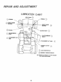
LUBRICATIONCHART
AXLE
PIVOT
SPINDLE
_
_
SPINDLE
FRONT WHEEL
BEARING
WHEEL
BEARING
_
_
ENGINE-
CLUTCH
PIVOT
1_
CLUTCH/BRAKE
PIVOT
CLUTCH/BRAKE
PIVOT
_
A
TTACHMENT
ARM
ATTACHMENT
MOWER
PIVOT
LIFT ARM
CLUTCH
SAE 30 MOTOR OIL
_GENERAL
_
24
PURPOSE GREASE
REFER TO PAGE 16 FOR ENGINE
OIL SPECIFICATIONS.
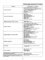
TROUBLESHOOTING
PROBLEM
CAUSE/REMEDY
Push Clutch/Brake
Pedal into Brake Position.
Move Attachment
Clutch Laver to "Disengaged
Position
Fil! Fuel Tank with Gasoline, Check Fuel Line and Carburetor
{clean tf necessary) Replace Fuel Filter
Check fuse for fault and replace
Recharge or replace Battery
Check Wiring
Replace Spark Plug and adjust gap
Adjust valves.
WILL NOT START
WILL NOT TURN
Charge Battery
Replace Ignition Switch
Depress Clutch/Brake
Pedal
Disengage
Attachment
Clutch
Replace Interlock Switch
Replace Solenoid
Replace Fuse
Check All Wire Connections
OVER
Replace
ENGINE CLICKS
BUT WON'T
START
Lever
Starter
Charge or ReplaceBattery
Place Throttle Control in "FAST"
position
and run starter several times to clear out gas
Remove and clean Fuel Tank and lines. Replace Fuel FiPtsr
Remove Air Filter and clean
Replace Spark Plug and adjust gap
Replace Battery
Check the wiring and Spark Plug
Drain Fuel Tank and Carburetor,
use fresh fuel and
replace Spark Plug
Make necesSary adjustments
to Carburetor
Adjust valves
Major Engine Overhaul
HARD TO START
ENGINE MISSES
(SEE iNDEX)
OR LACKS
Shift to a lower gear or reduce load
Remove and clean Fuel Tank; replace Fuel Filter
Remove and clean Air Cleaner
Make necesSary carburetor adjustments
Clean Air Screen
Add or change oil
Replace Spark Plug
Check Spark Plug and check for loose wires
Major Engine overhaul
Drain Fue! Tank and Carburetor end refill
Adjust valves
POWER
ENGINE OVERHEATS
Clean Air Screen
Add or chang_ oil
Clean Engine Cooling Fins
Remove and clean Muffler or replace
Remove and clean A/r Filter
Use fresh fuel and adjust Carburetor
NO LIGHTS
Check Fuse, Switch
Headlight
Bulbs
WON'T
and wire connections,
Replace
Check Fuse and replace
Replace Battery
Replace
Regulator
Reolace Alternator
CHARGE
OPERA TOR PRESENCE
SYSTEM
WILL NOT SHUT DOWN
WHEN
OPERA TOR LEA VES SEA T.
Note: This tractor te equipped
with an operator p_asance sans*
ing system. Any attempt by the operator to leave the seat with
the engine running and the attchment
clutch engaged
will shut
down the engine.
Engage attachment
clutch
Check aft wire connections
Check seat switch Check operator
Check PTO Switch.
25
presence
relay.
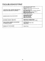
TROUBLESHOOTING
Place
Check
Check
throttle control in "FAST" position,
air pressure in tires
front to rest and,aide
to side mower
men
Use a slower ground speed
Check engines RPM's (refer to Carburetor
Replace mower blades
Reinstall mower
blades with top of blade
Replace w/th proper mower
blades
Re-adjust mower drive belt
UNSATISFACTORY
MOWER PERFORMANCE
UNEVEN DISTRIBUTION
OF CLIPPINGS
MOWER
BLADES
EXCESSIVE
WIND
ROWING
Replace
Replace
VIBRATION
STRIPPING
Adjustment)
up
Install new Mower Drive Belt
Reinstall Mower
Drive Belt
Adjust Mower Drive Belt
Replace Frozen Mandrel
Replace Frozen Idler Pulley
WILL NOT ROTATE
MOWER
adjust-
t
OR DROPPING
Bent or Unbalanced
Mandrel, Straighten
OF GRASS CLIPPINGS
Let grass dry out
Clean underside of Mower
Readjust Mower
UNEVEN
Readjust Mower
CUT OR SCALPING
26
Blades
Deck or replace
Deck
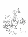
12 H.P, 38"
RmDmNGLAWN
TRACTOR--MODEL
NUMBER
$17.25_
SCHEMATIC
BLACK
RED
Tll
I
1
RED
INTERLOCK
cLUTCH/BRAKE
(PEDAL UP)
WHITE
!
SWITCHES
ATT'mENt
I
cLUTcH
(CLUTCH
OFFI
I
i
_'"__
SOLENOID
S
BLACK
M O IGNI.,,
_=
,_
IGNITION
SWITCH
FUSE
]
j l_
TION
BLACKV !
L
UNIT
i
_
BLACK
SEAT
SWITCH
(NOT OCCUPIED)
F
30 AMP
GG
l
,
BLACK
BLACK
' "O
SPARK
@
PLUG
(_,,,
IGNITION
POSITION
SWITCH
CIRCUIT
OFF
M-G
ON
B-L
DIODE
CHARGING
COIL
0
START
B-S
AT 3600
RPM, BATTERY
VOLTS AC (MIN)
IN LINE
BROWN
ORANGE
BLACK
LIGHT
SWITCH
WIRING INSULATED CLIPS
NOTE: IF WIRING INSULATED CLIPS
OR Ties WERE REMOVED FOR SERVICING OF UNIT. THEY SHOULD BE
REPLACED TO PROPERLY SECURE
YOUR WIRING.
27
CHASSIS
GROUND
I
3
3O
\
2
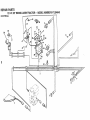
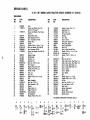
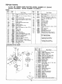
REPAmR PARTS
ELECTROCAL
(O
KEY
NO.
PART
NO.
1
2
3
4
5
6
7
8
9
10
11
12
13
14
15
16
17
18
19
20
21
7662J
110859X
121347X
109310X
1107t2X
104445X
7603J
109596X
STD365402
108824X
STD551125
STD541225
STD522505
73510400
108423X
11050400
719J
51t4J
I09553X
4207J
STD522507
A
DESCRIPTION
Bulb, Light
Harness, Light Socket
Harness, ignition
Key, Molded
Switch, Light
Switch, Interlock
Tray, Battery
Clamp, Hose
Switch, Ignition
Fuse, 30 Amp
Washer, Lock, 1/4
Nut, Hex Jam 1/4 - 20
*Bolt, He×, 1/4 - 20 x 1/2 Gr. 5
Nut, Keps 1/4 - 20
Cable Assembly
Washer Lock, Ext. Tooth, 1/4
Cover, Terminal
Cable, Battery
Switch,Interlock
Cable, Battery
*Bolt, Hex, 1/4 - 20 × 3/4
B
_11_
(_12
C
13
@is
_)
36
KEY
PART
22
23
24
25
26
27
28
STD551025
STD541025
121265×
102476X
STD541625
11030400
72240460
29
30
31
32
33
34
35
36
109081X
109787X
109788X
7192J
105687X
121305X
19221616
74641008
37
38
39
40
41
73951000
4171R
121264)(
121651X
11150400
42
-----
53203
101539X
121350X
"STANDARD
IDESCRIPT_
Washer 9/32 x 5/8 x 16 Ga.
u Nut, Hex 1/4-20
Battery, 12V.,
Terminal Guard
Wing Nut 1/4-20
Int./Exto Tooth Lockwasher 1/4
Bolt - Rd. Hd. Sq. Nk. 1/4 - 20 x
7-1/12
Solenoid
Bezel - Ignition
Nut, Ignition
Cable Tie
Tube, Ptastic
Switch, Runger
Washer 11116 x 1 x 16 Ga.
Screw - Slotted Pan Hd. No. 10_32 x
1/2
Nut - Keps No. 10-32 x 112
Clip - Insulated
Battery Caps Set
Decal, Sears
Lockwasher 1/4 Internal Tooth
Clip, Insulated
Sheet - Instruction, Tractor 15 °
Owners Manual
HARDWARDE--PURCHASE
LOCALLY
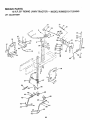
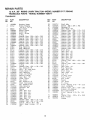
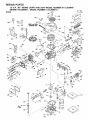
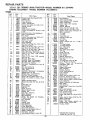
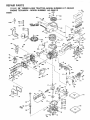
REPAUR$
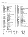
12 H.P. 38" RIDING LAWN TRACTOR - oMODEL HUMBER 917.254640
ENCLOSURE
C
53,
57
%
A
I
39
j
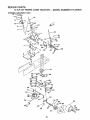
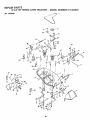
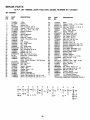
REPAIR PARTS
12 H,P. 38"" RaD G
LAWN
TRACTOR--MODEL
NUMBER
917o25 )
E_LOSU_
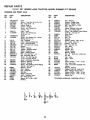
KEY
NO.
€0
.=b
PART
NO.
DESCRIPTION
1
2
120039X
17490612
3
17490616
4
5
6
7
8
9
10
11
12
1055 t 3X
105529X
73680500
121067X
109872×
19131312
STD523707
73680600
17490608
13
14
15
16
17
18
19
20
21
22
23
24
25
26
27
28
29
30
31
32
33
34
109873X
121144X
105465X
105464X
STD533707
105466X
108504X
108505X
108067X
108361X
108360X
19131210
106911X
110897X
74780816
109745X
106910X
105797X
105792X
105682X013
105678X
110853X
Seat
Screw, Hex Washer Thd. Roll
3/8-16 x 3/4 Type TT
Screw, Hex Washer Thd. Rolling
3/8-16-1
Bracket-Pivot, Seat
Bolt, Shoulder, 5/16-18
Nut - Crownlock 5/16-18
Spring, Seat
Fender
Washer 13/32 x 13/16 x 12 Ga_
_ Bolto Hex Washer Thd. Roll 3/8
Nut, Crownlock 3/8-16
Screw, Hex Washer Thd. Roll 3t816 x t/2
Bracket, Fender
Bolt-Shoulder
Footrest, L.H.
Footrest, R.H.
_Bolt, Carr. 3/8-16 x 3/4
Pad, Footrest
Bracket, Pivot, Grill, R.H.
Bracket, Pivot, Grill, L.H.
Pal Nut 1/4-20
Lens, L.H.
Lens, R.H,
Washer 13132 x 3/4 x 10 Ga.
Clip
Bezel, Headlight
Bolt, Hex 1/2-13 x 1
Strap Assembly - Grill
Washer
Hinge, Hood, L.H.
Hinge, Hood, R.H.
Hood Assembly
Grill Assembly
Bracket, Frame, Pivot, R.H.
KEY
NO.
PART
NO.
_$CRIPTI_
35
36
37
38
39
40
41
42
43
44.
45
46
47
48
49
110852X
106927X
106926X
121277X
121306X
121247X
105801X
105806X
105807X
4900J
108428X
109199)(
19132012
STD551150
19171912
50
51
52
53
54
55
56
57
58
59
60
61
62
63
64
65
66
67
68
STD523710
121440X
121441X
10681 t X
106812X
106974)(
106909X
121093X
2751R
19131614
19091216
120579)(
72170410
73900400
121251 ×
12125OX
121249)(
121246X
121248X
_STANDARD
A
B
O6
C
_
D
24
1
E
F
_
9
e
12
®l!
G
H
K
L
_6
u
27
29
@48
M
50
_
Bracket, Frame, Pivot, L.H.
Side Panel, R.H.
Side Panel, LH.
Chassis Assembly
Drawbar
Pan - Seat
Decal - Fender
Decal, Grill, Craftsman
Decal, Grill, Stripe
Decal, Clutch/Brake
Decal, 36"
Decal, V-Belt Ground Drive
Washer 13/32 x 1-1/4 x 12 Ga.
Lockwasher 112
Washer 17/32 x %3116 × 12
Ga.
_ BOlt, Hex 3/8-16 × 1
Guide - Belt, Lower, Eng. Pulley, L.H.
Guide - Belt, Lower, Eng. Pulley. R.H.
Decal - Stripe, Side Panel, LH.
Decal - Stripe, Side Panel, R.H.
Decal - Caution
Screw - Special
Cap - Spring
Clip
Washer 13/32 x 1 × 14 Ga.
Washer 9f32 × 314 × 16 Ge.
Pal Nut
Bolt, Carr 114-20 × 1 114
Nut, Hex Flange 1/4-20
Strip, Foam
Spring, Compression
Spacer, Split
Bracket, Switch Mount
Bushing, snap
HARDWARE--PURCHASE
N
P
3
12
_
I1
S
T
U
°'
0
_.47
R
LOCALLY
(_21
REPAmRS
12 H.P, 38" RIDING LAWN TRACTOR == I'_ODEL HUMBER 917.254640
DRIVE
HH
K
/3
63
I
66
18
59
58
72
88
/
OPTIONAL EQUIPMENT
Spark Arrester
34
32
EPAt
PA{ TS
12 H.P.
38"" RIDmNG _WN
TRACTOR--MODEL
NUMBER
917,254640
_nVE
KEY
NO.
!
PART
NO.
121342X
DESCRIP3"8ON
2
3
4
5
6
7
8
9
10
11
12
13
14
t05731X
120374X
STD551143
74770720
120302×
108635X
2949R
101326L
71070510
STD551131
101200K
2751R
17490628
15
16
STD551125
120898X
17
18
19
20
21
22
23
24
STD523727
73680600
STD580025
105703×
12000028
109167X
STD523710
17490512
25
26
27
28
29
30
31
32
33
34
35
36
37
38
39
40
41
42
108171X
109368X
4921H
106190X
STD523107
73680500
109370X
109369X
STD523707
121748X
106933X
110458X
71040412
105701X
STD561210
19151216
104777X
17490612
43
44
19131312
105730X
Engine, 12 HP. Tecumseh
Model No. 143.396012
Pulley, Engine
Valve, Drain Oil
_ Washer, Lock 7/16
Belt, Hex 7/16-20 × t-1/4
V-Belt, Drive
Muffler
Gasket
Deflector, Muffler
Hex Hd. Cap Screw 5/16-18 x 5/8
"Washer, Lock 5/16
Spacer
Clip
Screw, Ha× Washer Thd. Rolling
3/8-16 x 1-3/4
Bolt, Hex 3/8-16 × 2-3/4
Transa×le Foots, 6 Speed, Model No.
4360-7 (sea pages 40 and 41 far
parts breakdown)
"Bolt, Hax 3/8-16 x 2-3/4
Nut, Crownlock 3/8-16
° Key, Woodruff No. 9 3116 × 3/4
Pulley, Transaxle
Ring, Retainer
Bracket Transaxle
_ BOlt, Hex 3/8-16 x t
Screw, Hex Washer Thread Rolling
5/16-18 x 3/4
Support, Battery
Keeper, Belt, LH.
Retainer, Spring
Clamp
_ Bolt, Hex 5/16-18 x 3/4
Nut, Crewnleck 5/16-18 × 314
Strap, Locator
Keeper, Belt, R.H.
_ Bolt, Hex 3/8-16 x 3/4
Washer 25/32 x 1-5/8 x t6 Ga.
Knob, Shift
Rod, Shift
Bolt - Hex I/4-28 x 3/4
Washer - Shift Plate
_ Cotter Pin, 1/8 x 1
Washer 15/32 x 314 × 16 Ga.
Retainer, Belt
Screw, Hex Washer Thd. Rolling 3/8
t6 x 314
Washer 13132 x 13/16 x 12 Ga.
Keeper, Belt, Engine
A
O
C
D
F..
F
KEY
NO,
PART
NO.
45
46
47
48
49
50
51
52
53
54
55
56
57
58
59
60
61
62
63
64
65
66
67
68
69
70
71
72
73
74
75
76
77
78
79
80
81
82
109070X
4470J
4859J
106298X
105705X
STD523715
1_05709X
110812X
12000039
105710X
76020412
t05724X
109127X
t06888X
73350600
19131316
105758X
71673
109037X
8883R
121749X
STD571810
106918X
STD580105
104757X
59192
65139
106268X
106108X
109502X
6404J
12000001
121520X
STD533707
110422X
t05706X
106499X
17030_]08
83
84
85
86
87
88
105700X
t06919X
19091210
t 1050600
7152J
121851X
"STANDARD
G
I
J
DESCRPTJON
Retainer Bett
Spacer
Idler, Flat
Pulley, Idler
Bellcrank Assembly (Inc. Key No. 86)
*Bolt, Hex 3/8-16 x %112
Spring, Return, Clutch
Washer, Hardened
Ring, Klip
Link, Clutch
Pin, Cotter 1/8 x 3/4
Bracket, Clutch
Rod, Brake
Spring, Rod, Brake
Nut - Jam 318-16
Washer 13132 x 13116 x 16 Ga_
Rod, Brake, Parking
Cap _ Plunger
Shaft, Foot Pedal
Cover - Pedal
Washer 25/32 x 1-1/4 x 16 Ga.
_Pin, Roll, 3/16 x 1
Arm, Brake
"Key, Square 3/16 x 2
Cap, Hub
Cap, Valve
Stem, Valve
Tire, Rear - 18 x 9_50 × 8
Rim Assembly, Rear
Spacer
Spacer Engine Pulley
E-Ring
Strap, Torque, Transaxle
"Bolt, Carriage 318-16 x 3t4
Spring - Brake
Bearing
Retainer - Belt
Screw - Spider Lock No. 8-18 x
I/2 ABTPS
Spring
Rate, Shift
Washer 9t32 x 3t4 x 10 Ga.
Washer, Lock, Ext, Tooth 3/8
Tube, Tire (not furnished with tractor)
Spark Arraster
HARDWARE-PURCHASE
K
L
LOCALLY
M
030
012
_18
33
REPAmR PARTS
12 H.P.38" RIDING LAWN TRACTOR ==_,JIODELNUMBER 917.254640
51
5655
59
58 63
51
49
34
60
REPAnR PARTS
12 H.P. 38"
STEERING
KEY
NO.
1
2
3
4
5
6
AND FRONT
PART
NO,
109283X014
74180512
73510500
109816×
121299X
17080408
tO5621X
17190508
9
10
120088X012
17490608
11
12
13
14
15
16
17
18
19
20
21
22
2751R
105810×
10071OL
73940800
t00712K
100713N
100711L
tO9285X
105643X
STD523712
73680600
17041008
23
24
25
26
108456X
IO9284X
IO9432X
17490612
27
28
29
30
31
32
33
34
35
6266H
108684X
106126X
12000029
101930X
109068X
2882J
74580
71208
RaDJNG LAWN TRACTOR--MODEL
NUM R
9t7.25
AXLE
_$CRIPTION
Dash
Screw - Truss Hd. 5/16-18 x 314
Nut - Keps 5116 - 18
Nyliner, Snap In
Control - Throttle
Screw - Hex Thread Cut.
1/4-20 × 1/2
Dash - Lower
Screw - Hex Thread Cut.
5/16-18 x 1/2
Saddle
Screw - Hex Washer Hd., Thread
Rolling 3/8-16 x 1/2
Clip - Insulated
Decal - Steering Wheel Cap
Insert - Steering Wheel
Nut - Hex Jam Lock 1/2-20
Washer
Wheel - Steering
Adapter - Steering Wheel
Sleeve - Steering
Shaft - Steering Upper
"Bolt - Hex 3/8-16 x 1-1/4
Nut, Crownlock 3/8-16
Screw - Hex Self Tap. No.
10-16x 1/2Type ABTPS
Decal - Instruction, Operating
Bushing - Steering
BrackErt- Steering
Screw - Hex Washer Thread Rolling
3/8-16 x 3/4 Type TT
Bearing - Thrust
Gear - Sector
Key - Woodruff
Klip Ring
Washer, Hardened
Shaft - Steering, Lower
Pin - Drive 3/16 x 1
Spacer .627 x .88 x .695
Bushing
A
B
c
D
KEY
NO.
PART
NO.
_SCRJPT|_I_
36
37
38
39
40
4t
42
43
108683X
105663X
105664X
74761060
105669X
110438X
73901000
17490508
44
45
46
47
48
49
50
5t
52
53
54
55
56
57
108685X
3366R
105715X
120754×
19131416
760204t2
STD551137
STD541137
105727X
105656X
105654X
278H
9040H
106732X
58
59
60
61
62
63
59192
65139
106222X
121749X
104767X
59904
64
65
66
67
68
69
110130X
11150500
110307X
121748X
19272016
121232X
Rod - Steering
Support - Saddle, Rear
Support - Saddle, Front
Bolt - Hex 5/8-11 x 3-3/4
Axle - Front
Spacer, Bearing, Front Axle
Nut - Lock, Flange 5/8-11
Screw - Hex Washer Thread Rolling
5/16-18 x 1/2 Type TT
Gear, Pinion
Bearing
Rod - Tie
Bushing
Washer 13/32 x 7/8 x 16 Ga.
Pin - Cotter 1/8 x 314
Washer - Lock 3/8
Nut - Hex 3/8 - 24
Link - Drag
Spindle - L.H.
Spindle - R.H.
Fitting - Grease
Bearing - Flange
Rim - 6" - Front (Inc. 2 Each Key
No. 56)
Cap = Valve
Stem - Valve
Tire
Washer 25/32 x 1-114 x 16 Ga.
Cap - Hub, Front
Tube - Front (Not furnished with
tractor)
Retainer, Steering
Washer, Lock, Int, Tooth 5/I 6
Stop - Mower, Clutch Lever
Washer 25/32 x 1-5/8 x 16 Ga.
Washer 27132 x 1-1/4 x 16 Ga.
Spindle Cap
_STANDARD
E
8
35
F
G
HARDWARE--PURCHASE
LOCALLY
REPAQR PARTS
12 H.P, 38" RIDING LAWN TRACTOR - - MODEL NUMBER 917.254640
LIFT ADJUSTMENT
21
20
\\
15
9
16
I=
°_B
%
E
¥
12
- :35 F" ,
36
t9
20
REPASR PARTS
12 H.P. 3S'" RUDDNGLAWN TRACTOR--MODEL
NUMBER 917.2546,
LiFT ADJUSTMENT
KEY
NO.
PART
NO,
DFSCRIPTION
KEY
NO.
PART
NO.
1
2
3
4
5
6
7
106448X
106932X
106451X
73680600
106452X
19171713
17021008
8
9
10
1!
12
13
14
106447X
121221X
109202X
101335K
9151R
6999R
17490612
15
16
17
18
19
20
21
22
23
24
25
26
27
28
29
3O
31
106901X
106920X
121794X
106921X
19292016
12000022
100734K
Lever, Clutch, Mower
Knob
Bolt, Shoulder
Nut, Crownlock 3/8-16
Bracket, Switch, Interlock
Washer 17/32 x 1-1/t6 x 13 Ga.
Screw, Hex, Tapping, No. 10-24 x
1/2
Support, Lever, Clutch
Cap, Fuel
Tank, Fuef
Line, Fuel
Grommet
Clamp - Hose
Screw, Hex Washer Thd. Rolling
3/8-t6 x 3/4
Clamp - Tank, Fuel
Panel, Dash, L.H.
Cover, Access
Panel, Dash, R.H.
Washer 29/32 x 1-1/4 x 16 Ga,
E Ring
Knob
32
33
34
35
36
37
38
39
40
4t
42
43
44
45
46
47
48
49
50
51
52
53
105723X
109413X
4939M
110029X
110447X
110448X
121598X
105848X
121599X
106308×
STD541250
9135R
19171516
4921H
105864X
106444X
STD523707
109728X
76020412
106446X
19131410
105764X
54
55
56
57
58
59
60
61
62
105767X
1068 IOX
72140606
108236X
110807X
! 10739X
73980600
73360700
73710700
STD54t237
110809X
76020308
2876H
19131016
110810X
19151216
12000037
120420X
105768X
_Nut, Hex Jam 3/8-16
Rod, Adjust, Lift
Pin, Cotter 3/32 x t/2
Spring
Washer 13132 x 5/8 x 16 Ga,
Trunnion - Depth Stop
Washer 15/32 x 3/4 x 16 Ga.
Klip Ring
Shaft, Lift
Lever, Assembly
DESCRIPTION
Plunger
Grip, Handle
Retainer, Spring
Link, Lift
Trunnion, Lift
Link, Lift, Adjustable
Arm, Suspension, R.H.
Bolt, Shoulder, 3/8-16
Arm, Suspension, L.H.
Trunnion, Lift, Lower
_Nut - Hex 1/2-13
Retainer, Spring
Washer 17t32 x 15/16 x 16 Gao
Retainer, Spring
Bracket, Suspension
Bracket, Betfcrank
* Bolt, Hex 3t8-16 x 3/4
Bellcrank Assembly
Pin, Cotter, I18 x 314
Rod, Clutch, Primary
Washer 13/32 x 7/8 x 10 Ga.
Rod Assembly - Lever, Lift
(Includes Key 32)
Pin - Groove
Spring - Extension
Screw 3/8-t6 x 3/4
Bracket - Switch
Nut - Special
Washer _ Spring
Nut - Flangelock 3/8-16
Nut, Hex Jam 7/16-20
Nut, Crownlock 7/16-20
*STANDARD
A
B
C
O
,_
37
HARDWARE--PURCHASE
E
60
LOCALLY
REPAIR PARTS
12 H.P. 38" RBDnNG LAWN TRACTOR
38"
.-- MODEL NUMBER
917.254840
MOWER
44
44
43
15
A
54
/
55
_/4
I8
48
45
58
/
59
I
54
38
REPAIR PARTS
•
12 H.P. 3S'" RtDDNG LAWN TRACTOR--MODEL
38"
NUMBER 917.254640
MOWER
KEY
N 0.
PART
NO.
DESCRIPTION
KEY
NO.
PART
NO.
DESCRIPTION
1
2
3
4
5
6
7
8
9
10
11
12
13
14
15
16
17
18
19
20
21
22
23
24
25
26
27
28
29
30
31
32
33
34
35
36
37
106085X
121259X
8417J
73680600
19111216
72140505
!05896X
110452X
106734X
106735X
106736X
105814X
105304X
105662X
105744X
105872X
109835X
STD523707
73680500
109598X
109597X
STD533107
3713J
109503X
109504X
V-Belt
Housing
Runner, R.H.
Nut, Crownlock 3/8-16
Washer 11/32 x 3/4 x 16 Ga.
Bolt, Carr., 5/16 - 18 x 5/8
Bracket, Deflector
Pushnut
Spring, Deflector
Rod - Hinge
Deflector - Shield
Decal, V-Belt Mower Drive
Cap
Link, Parallel
Pin - Hinge, Front
Stop, Link
Pin - Hinge, Rear
Bdlt 3/8-16 x 3/4
Nut, Crownlock 5/16-18
Bracket, Lift, R.H.
Bracket, Lift, L.H.
Bdlt, Cart. 5/16-18 x 3/4
Instruction - Caution Decal
Support, Arm
Stop, Deck, Front
Decal - Safety Standard - Not Serviced
Guide Belt
Bdtt 3/8-16 x 2
Arm, Idler
Spacer - Retainer
Pulley - Idler
Washer, Wear, 1/16
Keeper, Belt
Mandrel Assembly
Plate, Support Mandrel
Screw, Hex Washer Hd. 3/8-! 6 x 3/4
Screw, Hex Washer Hd. 3/8-16 x 1-1/4
38
39
40
41
42
43
44
45
46
47
48
49
50
51
52
53
54
55
56
57
58
59
60
61
62
63
64
65
66
67
68
69
70
71
72
--
12t 263X
19132012
STD551137
STD623715
108250X
108235X
4921H
STD560907
I09892X
76020616
108247X
72140606
108243X
108241X
105857X
108673X
106578X
106463X
108249X
106456X
!00672K
100673L
19131614
74760688
7631J
19111016
72140610
121343X
122314X
76020308
72110506
STD522507
I09893X
73680400
110445X
122215X
_STANDARD
Blade
Washer 13t32 x 1-1/4 x 12 Ga.
V_asher, Lock 3/8
Bdlt, Hex, 3/8-24 x 1-1/2 Gr. 5
Spring, Extension
Rod - Clutch, Mower
Spring - Retainer
Pih, Cotter 3/32 x 3/4
Rock Shaft Assembty
Pin, Cotter, 3/16 x 1
Rod, Brake, Primary
BSIt, Carr. 3/8-16 x 3t4
Bracket, Pivot, R.H.
Bracket, Pivot, L.H.
Bracket, Suspension, Rear, R.H.
Bracket, Suspension, Rear, L.H.
Brake Assembly
Rod, Brake, Secondary, L.H.
Rod, Brake, Secondary, R.H.
Bracket, Brake, Pivot
Spacer, Brake
Bracket, Support
Washer 13/32 x 1 x 14 Ga.
Bolt, 3/8-16 x 5-1/2
Runner, L.H.
Washer 11/32 x 5/8 x 16 Ga.
Bolt, 3/8-16 x 1-1/4
Decal - Warning
121317X
STD523720
108832X
106902X
12t316X
106513X
102669X
121687X
100668L
17490612
17490620
A
B
22
C
22
_5
_19
® 19
O
49
E
6
F
G
H
Spacer
Pin, Cotter, 3/32 x 1/2
Bolt, Carriage 5/16-18 x 3/4
Bdlt Hex 1/4-20 x 3t4
Washer, Special
Nut, Crownlock 1/4-20
L.H. Mandrel Support
Mower Assembly,Complete
HARDWARE--PURCHASE
LOCALLY
K
L
M
37
68
o
_19
_
4 @ 19
@ 4
_)
39
71
25
28
./
/
29
f
3O
J
26
/
31
27
•
32
36
1
33
"
34
_519
19
f
53
/
40
/
42
/
43 _"
/
54
44
/
/
45
55
46
,/
56
47
57
48
59
49
/
56
50
51
55
19
/"
60
/
59
4O
/
REPAIR PARTS
12 H.P. 38"
TRANSAXLE
RIDING
FOOTE
LAWN TRACTOR--MODEL
- MODEL NUMBER
4360-7
NUMBER
917.254640
PART
NO.
D_=SCRIPTION
39
40
41
42
43
43
43
43
43
43
43
43
43
43
43
43
43
44
45
46
47
48
49
50
51
52
53
54
55
56
57
58
59
60
61
62
63
64
65
66
67
68
69
70
71
72
12047tX
120472X
105928X
110084X
108983X
105930X
105931X
! 05932X
3417J
106097X
2264J
106098X
2265J
106586X
t06587X
t 06588X
2263J
120473X
105933X
106151X
120407X
106589X
120408X
105937X
2226J
2272J
2263J
120474X
110081X
10594;X
110071X
t20952X
! 10082X
120475X
120476X
120961. X
64260
108989X
120953X
1 20954X
120955X
108992X
108996X
120956x
73810500
t06596X
73
74
75
120993X
120951X
120816X
Shaft. ldter
Spacer..635
x .875 x .755
Sprocket.
9T
Gear. Bevef. 42T.
Washer.
Plain..758
x 1.12
Washer.
Plain..758
x 1.12
Washer.
Plain..758
x 1.12
Washer.
Plain..758
x 1.!2
Washer.
Plain..758
x 1.25
Washer.
Plain..758
x 1.25
Washer.
Plain..758
x 1.25
Washer.
Plain..758
x 1.25
Washer.
Plain..758
x 1.25
Washer.
Plain..758
x 1.25
Washer.
Plain..758
x 1.25
Washer.
Plain..758
x 1.25
Washer.
Plain..758
x 1.25
Shaft. Drive
Gear. Spur. I2T.
Gear. Spur. 15T.
Gear. Spur. 20T.
Gear. Spur. 25T.
Gear. Spur. 28T.
Gear. Spur 31T
Washer.
Plan..632
x 1.00
Seal _e!t
Washer.
Pta_n..758
x 1.25
Axte. LH.
Gear. Miter. 15T.
R_n9, Retaining
Gea'. Spur. 32T.
Shaft. Cross
Gea'. Miter
15T.
Axle R.H.
Ho._Sing Lower
Puck. Fr_ction
D_SC Brake
Spacer
Ja_', B_ake
Pro. Dowe!
Screw. Tapping.
5/16 - 18
Le._er. Actuating
Washer.
Plain..321
x 1.00
Bracket.
Anb-Rotat_on
Nut. Lock 5/16-24
Screw. Tapping.
5,16-18
x
Lg.
Washer.
Plain.
.343 x .81
Puck. Friction
Grease
TRANSAXLE
KEY
NO.
PART
NO,
120458X
2274J
3
4
5
6
7
8
8
8
8
8
8
8
9
10
11
11
11
11
11
11
11
1t
11
1t
12
13
t4
15
16
17
18
19
20
2!
22
23
24
25
26
27
28
29
30
31
32
33
34
35
36
37
38
68003
105904X
105905X
120460X
120461X
120462X
120463X
120464X
120465X
120466X
83818
120467X
2286J
2267J
3413J
2233J
2232J
2231J
2230J
2229J
2228J
2227J
2226J
!05906X
6725J
t20415X
2257J
110077X
110078X
105909X
!05910X
105911X
I08976X
105913X
120468X
2242J
!20469X
2244J
105916X
t20470X
110070X
108977X
109254X
120405X
108980X
120406X
108455X
105925X
2232J
108978X
1t0079X
DESORIPTION
Housing.
Upper
Screw. Tapping.
1/4-20
x.734
Lg.
Ball. Detent
Spring,
Detent
Screw.
Set
Ass'y,,
Shifter
O-Ring
Washer.
Plain..505
x .942 x
Washer,
Plain..505
x .942 x
Washer,
Plain..505
x .942 x
Washer.
Plain..505
x .942 x
Washer.
Plain..505
x .942 x
Washer.
Plain..505
x .942 x
Washer.
Plain..505
x .942 x
Ring. Retaining
Ring. Retaining
• Washer.
Plain..632
x 1.00 x
Washer.
Plain..632
x 1.00 x
Washer.
Plain..632
x 1.00 x
Washer.
Plain..632
x 1.00 x
Washer.
Plain..632
x 1.00 x
Washer.
Plain..632
x 1.00 x
Washer.
Plain..632
x 1.00 x
Washer.
Plain..632
x 1.00 x
-Washer.
Plain..632
x 1.00 x
• Washer.
Plain..632
x 1.00 x
O-Ring
Washer.
Plain..632
x 1.38 x
Key. Woodruff.
#9
Ass'y..
Kit. input Shaft
Pinion. Bevel. 14T.
Ring. Retaining
Chain. 24 Pitches
Bearing.
Flange
Gear, Spur. 14T.
Collar, Clutch
Key. Clutch
Key. Woodruff.
fl3
Shaft. Intermediate
Key. Woodruff
_.61
Ring. Retaining
Sprocket.
18T.
Spacer
Gear. Spur. 37T.
Gear. Spur. 351.
Gear. Spur. 30T.
Gear. Spur. 25T.
Gear. Spur. 22T.
Gear. Spur. 19T
Washer.
Plain..640
x 1.37 x
Washer.
Plain..632
x 1.00 x
Spacer..630
x 1.00 x .169
Ass'y.:
Gear. Combo..
12T.
35T.
KEY
NO,
.006
.010
.0!5
.020
.026
.030
.040
.010
.020
.026
.031
.036
.041
.046
.050
.060
.082
046
.081
.026
&
41
x
x
x
x
x
x
x
x
x
x
x
x
x
.010
.015
.020
.025
.020
.025
.031
.035
.040
.045
.050
.055
.062
x .060
x .062
x 2.25
x .055
1.44
x .059
REPAIR PARTS
ENGINE
_39
_"'_"
58
127
//_
/
i j /
_34
1
40 i
42
33
37
REPAIR PARTS
12 H.P.
38"
RSDING
ENGRNE TECUMSEH
LAWN
TRACTOR--MODEL
- MODEL NUMBER
NUMBER
917.254640
143.396012
ENGINE
Ref.
No.
1
2
3
4
5
6
7
8
9
10
!1
12
13
14
15
16
17
18
19
19
19
19A
19A
19A
20
20
20
21
22
23
23A
24
25
26
27
28
28A
29
30
31
32
33
34
35
36
37
38
39
4O
41
42
43
44
45
45A
46
47
49
50
51
Part
No.
35323A
28277
35324
35520
29916
650548
35521
35319
35326
650561
Ref.
No.
Part Name
Cylinder
Assy.
'i"i'ncL
Nos.
8
_3_
13i
52
53
53
54
54
55
56
57
58
59
Washer, Fiat
Rod, Governor
Lever, Governor
Clamp, Throttle lever
Screw, Hex washer hd., 8432 x 5/16
Spring, Control
Seal, Oil
Baffle, Blower housing
Screw, Hex washer hd. Durlok, 1/4-20
x 5/8
35336A Crankshaft Assy. (Counterbalance)
35327
Gear, Counterbalance
27652
Pin, Dowe_
29826
Screw, Hex washer hd., 10-32 x 3/4
30322
Nut 8- Lockwasher, 8-32
29918
Washer, E.T. Lock
29216
Nut, Lock, 10-32
29642
Ring, Retaining
35339
Piston, Pin 8. Ring Assy. (Std.} (Incl.
Nos. 19A, 20 8.21)
35340
Piston, Pin 8- Ring Assy. (.010 oversize) (Incl. Nos. 19A, 20 8. 21)
35341
Piston, Pin 8- Ring Assy, (.020 oversize) (IncL Nos, 19A, 20 8- 21)
35329
Piston 8. Pin Assy. (Std.) (incl. No. 21)
35430
Piston 8- Pin Assy, {.010 oversize)
{lncl. No. 21)
35431
Piston 8. Pin Assy. (.020 oversize)
(Incl, No. 21)
34866
Ring Set, Piston (Std.)
34867
Ring Set, Piston (.010 oversize)
34868
Ring Set, Piston (.020 oversize)
31919
Pin, Piston pin retaining
35330A
Rod Assy., Connecting (incl. Nos. 23
8. 23A)
650908
Bolt, Connecting rod
650882
Bolt, Connecting rod
35313
Lifter, Valve
35314A
Camshaft (Mechanical Compression
Release) (incl. No. 24)
35315
Weight Assy., Counterbalance
35316
Extension, Blower heusing
650128
Screw, Hex hd. Seres, 10-24 x 1/2
30063
Screw, Hex washer hd. Sems, 1/4-20
x 1/2
*35317
Gasket, Mounting flange
3571l
Flange, Mounting (Incl, Nos. 32, 33 8.
34)
31356
Pump Assy., Oil
31927
Plug, Oil drain
35319
Seal, Oit
35712
Shaft, Governor
31707A
Spacer, Governor gear
35479
Washer, Flat
35321
Gear Assy,, Governor
35322
Spool, Governor
29193
Ring, Retaining
65O833
Screw, Hex washer hd, Powerlok,
1/4-20 x !-3/16
32589
Key, Flywheel
611093
Flywheel
65O88O
Washer, Lock
650881
Nut, Flywheel
35135
Solid State Assy.
610118
Cover, Spark plug
650872
Stud, Solid state assy.
650814
Screw, Hex hd. Sems, 10-24 x 1
*35306
Gasket, Cylinder head
353O7
Head Assyo, Cylinder
730218
Vaive Guide Kit (lncl, 2 of No. 52)
6O
60A
61
62
63
64
65
Part
No.
792035
35308
35433
35309
35432
650691
650690
650746
650692
34046
t'33481
1-3348t
35475
35310
t.33484
650168
32610A
66
67
68
69
70
71
72
73
74
75
76
77
78
79
80
t'33509
t'34410
33510
33507
335O8
"r'35295
35296
65O878
35297
35298
t'28264
35466
t*35299B
35300
t'65o879
8!
82
83
84
85
86
86A
87
88
89
90
9OC
91
92
93
94A
t'650903
*27896
28423
28424
28425
3535O
34148
650128
35301
650128
650517
35O43
*33263
35304
35522
35524
94B
94C
94E
95
96A
97
98
99
100
101
33802
650777
35516
35523
650902
792028
"33515
35288
650738
35338A
Part Name
Ring Retaining
Valve, Exhaust (Std.}
Valve, Exhaust (1/32" oversize)
Valve, Intake (Std.)
Valve, Intake (1/32" oversize)
Washer, Flat
Washer, Belleville
Screw, Hex hd., 5/16-18 x 3/8
Screw, Hex hd,, 5/16-!8 x t-3/4
Resistor Spark plug (Champion
RL86C or equivalent)
"O" Ring
"'0" Ring
Tube, Push rod
Housing, Rocker arm
"O" Ring
Washer, Flat
Screw,
Flanged hex hd., 1/4-20
x
29/32
"0" Ring (intake)
"0" Ring (Exhaust)
Cap, Valve spring
Spring, Valve
Cap, Valve spring keeper
"0'" Ring
Guide, Push rod
Stud, Rocker arm
Arm, Rocker
Bearing, Rocker arm
Nut, Lock (incl. No. 81)
Rod, Push
"0'" Ring Assy. (Incl. No. 80}
Cover, Rocker arm housing
Screw,
Truss
hal.
w/sealing
Iockwasher,
8-32 x 1/2
Nut, Hex Jam
Gasket, Valve cover
Body, Breather
Element, Breather
Cover, Valve spring box
Tube, Breather
Spring, Coil
Screw, Hex hd. Sems, t0-24 x 1/2
Extension,
Blower housing
Screw, Hex hal° Sems, 10-24 x 1/2
Screw, Hex hd. Sems, 1/4-20 x 27/32
Tube, Carburetor
Gasket, Carburetor to intake pipe
Pipe, Intake
Link, Governor
Bracket Assy., Control (Incl. Nos. 94B
8 94C)
Spring, Compression
Screw, Fil. hd., 6-32 x 21/32
Link, Control bracket
Link, Governor spring
Screw, Hexwasher
hd., Seres, 10-32x
7/16
Screw, Hex hd. Sems, 5/16-18 x 7/8
Gasket, intake pipe
Brace, Intake pipe
Screw,
Hex
washer
spinlock
hd.
thread forming,
1/4-20 x 5/8
Housing, Blower
_lndicates Part Included in
Gasket Set, Ref. No. 174.
43
REPAIR PARTS
12 H.P. 38" RnDING LAWN TRACTOR--MODEL
NUMBER
ENGDNE TECUMSEH - MODEL NUMBER 143.3S60!2
917.254640
:,°_F'-139
ENGINE
j8
105 _
159
9
t20
%
96A
169
94E
51
62
REPAgR PARTS
12 H.P.
38"
RIDING
ENGmNE TECUMSEH
LAWN
TRACTOR--MODEL
- MODEL NUMBER
NUMBER
917.254640
143.396012
ENGINE
Ref.
No.
Part
No.
t02
30063
103
29747B
104
105
106
35290
650273
30063
115
115A
118
119
119A
120
121
35411
29774
26460
34279A
27793
28942
Ref.
No.
Part Name
Screw, Hex washer hd. Sems, i/4-20
x 1/2
Screw, Phil. Hex hd. Sems, 5/16-24 x
21/32
Cover, Cylinder head
Screw, Hex hd. Sems, 5/16-18 x 5/8
Screw, Hex washer hd. Sems, 1/4-20
x 1/2
Screen, Starter
Rivet (Can be purchased locally)
Line, Fuel
Clamp, Fuel line
Filter Fuel {IncL No. 119)
Clip, Conduit
Screw, Hex washer hd. Sems, 10-32 x
3/8
125
126
127
128
129
130
131
132
133
134
136
137
138
138
140
141
35574
35576
35499
35402A
35404
35403
650875
*33629
35286
*35408
35405
650885
650825
650886
35406
35407
CARBURETOR
Tube, Oil fill
Dipstick, Oit
"0" Ring
Body, Air cleaner
Filter, Poly pre-cleaner
Element, Air cleaner (Incl. No. 138)
Screw, Fit. hd. Seres, 10-32 x 5-1/4
Gasket, Air cleaner elbow
Adpater, Air cleaner
Gasket, Air cleaner-to-housing
Cover, Air cleaner
Screw, Truss hd., 1/4-20 x 3-1/2
Nut 8- Lockwasher,
1/4-20 x (Sealing}
Nut, Wing !/4-20
Fitting, Breather tube
"O" Ring
Part
No.
i42
3 17
t43
650887
150
151A
650873
611113
152
153
154
157
158
159
160
169
610935
610921
610922
33997
35437
27275
34113
30063
170
170A
171
173
t74
175
34346
34686
632518
33605
35331B
35332
Part Name
Plate, Support
Screw, Hex washer hd. self-drill, selftap, 1/4-20 x 1
Screw, Hex hd. Some, 1/4-20 x 3/4
Coil Assy., Alternator
(3 Amp D.C.)
(incl. Nos. 152, 153 8 154)
Diode
Connector,
Body
Termfnal, Female
Clip, Oi filt tube
Clip, Oil fill tube
Clip, Wire
Plug, Starter
Screw, Hex washer hd. Sems, 1/4-20
x 1/2
Decal, Instruction
Decal, Name
Carburetor
(Incl. No. 91)
Starter Motor (12 Volt)
Gasket Set (Incl. items marked t)
"'O"4_ing
Kit (Incl. items marked t)
RPM Speed Settings:
Low, 1700; High, 3500.
*indicates
Parts Included in
Gasket Set, Ref. No. 174.
¢lndicates Parts Included in
"O" Ring Kit, Ref. No. 175.
NO, 632518
Ref.
No.
5A
24
32
J
45
Part
No.
!
2
3
4
5
6
7
8
9
10
11
12
632518
632471
632244
632517
650506
530766
650417
632472
632473
632429A
*630748
*631027
*631021
13
14
15
16
21
22
23
24
25
27
29
29A
30
31
32
631022
632019
*631024
*631867
27110
,632470
530740
*632281
*631028
531184
63197l
631183
630739
63177.5
632347
Part
Name
Carburetor
Shaft 8 Lever Asay., Throttle
Spring, Throttle return
Shutter, Throttle
Screw, Rd. hd., 4-40 x 3/16
Spring, Idle regulating screw
Screw, Idle regulating
Shaft E_ Lever Assy., Choke
Spring, Return
Shutter, Choke
Plug, Welch
Plug, Welch
Inlet Needle,
Seat 8- Clip Assy.
(Incl. No. 13)
Cllp, Inlet needle
Float, Carburetor
Shaft, Float
Bowl, Float
Gasket, Bowl-to-body
Nut, Float bowl
"O" Ring
Screw, Idle adjustment
Gasket, Bowl-to-body
Washer
Seal, Dust
Sea!, Dust
Washer, Flat
Fitting, Fuel
Repair Kit (Incl. items marked *)
REPAaR PARTS
12 H.P.
38"
RIDnNG LAWN
ENGINE TECUMSEH
TRACTOR--MODEL
- MODEL
NUMBER
NUMBER
9!7,254640
143.396012
ENGINE
STARTER
MOTOR
NO.
33605
14
11
18
13
17
19
No.
12
46
No.
1
2
3
4
5
6
7
8
9
10
11
12
_5
33451
33842
33430
33431
33432
33_3
33450
33434
33703
33759
33712
33705
13
14
15
16
17
18
19
33440
590500
33449
33706
650168
650723
34685
Part
Name
Starting Motor, Complete
Cover, Dust
Ring, Retainer
Retainer, Spring
Spring, Anti-drift
Gear
Nut. Engaging
Nut, Lock
Cap Assy., Drive end
Armature
Housing Assy.
Card Assy., Brush (Incl. No. 12)
Brush _ Spring Kit (Incl. 4 pcs. of
No. 13)
Spring, Brush
Washer, Thrust
Bolt, 10-32 x 4-1/4
Cap Assy,, Commutator end
Washer, Fiat
Nut, Hex
Terminal Insulators
47
48
49
AttachmentsThatAddto the UsefulnessofYourCraftsmanLawnTractor
Searsoffersa widevarietyof attachmentsthatfit your tractor.Manyof theseare listedbelowwith briefexpfanationsofhowtheycan helpyou. Thislist
wascurrentatthetimeof publication:however,itmaychangeinfutureyears-- moreattachmentsmaybe added,changes(includingchangesin thestock
number)may be madein theseattachments,or somemay no longerbe available.
Mostof theseattachmentsdo not requireadditionalhitchesor conversionkits (thosethat do are indicated)and are designedfor easyattachingand
detaching.You may orderthese attachmentsatmost Searsretailstores,catalogsalesoffices,and throughthe catalog.
PERMANEX BAGGERlets youcollectgrassclippingsand leavesfor a healthierneater-lookinglawn,Two Permanexcontainershold 30-gallonplastic
bags.Stocknumber71-24940
LAWNSWEEPERSlet you collectgrassclippingsand loaves.
71-24030
71-24032
30-in.
32-in.
9.0 cu. It.
10.0cu.ft.
71-24033 High-Performance
71-24038
32 in.
38-in.
11.5cu. ft.
12.5cu. ft:
LAWNVACSfor powerfulcollectionsof heavygrassclippingsand leaves.Wandattachmentto pick up debrisin hard-to-reachplaces.
71-2452
3HP
12 bu.
71-2647] chute
Dumpcart
CARTSmake haulingeasy.
71-24353
4 cu. ft.
400 fb.
71-24354
71-24355
10cu. ft.
10cu. ft.
1,000lb.
1,000lb.
Haulingcart
Dumpcart
71-24356
14cu. ft.
1,250lb.
Dumpcart
ROLLERfor smootherlawnsurface.36-inchwide,18 inchdiameterwater-tightdrumholdsup to390 lb.of weight.Roundededgespreventharmto turf.
Adjustablescraperautomaticallycleans drum.Stocknumber71-24084.
SPREADER/SEEDERS
makeseeding,fertilizing,andweedkillingeasy.Broadcastspreadersare alsouseful forgranularde-icersand sand.
7t-24194
Droptype,36 inch. 12 in. semi-pneumatic
wheets.100 lb.capoill steel hopper.
71-24394
Broadcastsovera5to8footswath.701b.capacitys_elhopper.Noncor_sivespreadingspinner,
nylongearbox,sta[nlesss_el
shaft.
71-24395
Broadcasts8 to 10 foot swath.160 lb. capacity.No-rust
po]ypropylenehopl_r and impeller.Vinyl hoppercover.
CORINGAERATORtakessmaUplugsoutofsoiltoallowmoistureand nutrientstoreachgrassroots.36-inchswath.24 hardenedsteelcoringtips.150
lb.capacityweighttray. Stocknumber71-25351
AERATORpromotesdeeproot growthfor a healthylawn. Tapered2.5"steel spikesmountedon 10-in.diameterdiscspunctureholesin soilat close
intervaIsto letmoisturesoakit. Steelweighttray forincreasedpenetration.Stocknumber71-2435.
DETHATCHERloosensand flipsthatchand mattedleavesto lawnsurfacefor easy pickup. Twentyspringtineteeth.Usefulto preparebareareasfor
reseeding.40 inchrear mount:Stocknumber71-24313.38inchfront mount:Stocknumber71-24301.
SPRAYERS use12-voltDCelectricmotor thatconnectstothetractorbatteryor other12-voltsource.Includesboomsforautomatiosprayingwhenpulling,
andhand heldwandfor spot spraying.Wandhasadjustablespraypattern.For applyingherbicides,insecticides,fungicides,and liquid fertilizers.
71-2458
50 psi maximumpressurewith 12 foot wandlength.Spraysup to25 feet with wand.
71-24398
25 psi maximumpressure
with 10 foot wandlength.Spraysup to 18feet with wand.
SNOWBLADEfor snowremovaionly. 14 inchhigh,42 inchwideblade clears38 inchpathwhenangtedleft or right.Raises,lowerswithsidelever.
Adjustableskids:replaceable,reversiblescraperbar.(Usewith tirechains,wheelweights,or rear drawbarweight).Stocknumber71-24407.
SNO_HROWER has40-inchswath.Drum-typeauger handlespowderyandwet/heavysnow.Mountseasilywith simplepin arangement.Discharge
chuteadjuststo 210degreearcfrom tractorseat.6-inchdiameterspoutdischargessnow 10to 50 ft. Lift controlledat tractorseat.(Usewith tirechains,
wheelweights,or rear drawberweight).StockNo. 71-24072.
TIRECHAINSare heavyduty; closelyspacedextra-largecrosslinksgive smoothride,outstandingtraction.StockNo. 71-24952.
WHEELWEIGHTSforrear wheelsprovideneededtractionforsnow removalor dozingheavymaterials.Inpairs.StockNo. 71-24434(30 lb. each)
TRACTORCABhas heavydul! vinylfabricovertubularstee_frame,ABSplastictop; clearplasticwindshield
offers360 degreevisabilill.Hingedmetal
framedoorswith catch.Keepsoperatorwarm anddry. Removevinyl andwindshieldIoruse as sunprotectorin summer.StockNo. 71-24171.
Optionalacoessoriesfor tractorcab:tinted/temperedsolidsafetyglassw[ndsh[edwith handoperatedwiper(StockNo.71-26168);12woltambercaution
lightfor mountingon cab top (StockNo. 71-26169).
TRACTORCOVERprotectstractorfromweather.Madeof Evolution3 fabdc (water-repellent,extremelybreathable,light weight,soft, non-abrasive,
pliablein all temperatures,durable,stain-tear-puncture
resistant,will notshrink or stretch).StockNo. 71-2460f.
5O
SIGHT
A_D
HOLD
THIS
SKY
L|_E
OR TREE
Operate
greater
,/our
_han
airy
to
CautiOn
prevent
t_ppmg
Or |OSS of control,
when
changing
dlrecHon
on slopes.
LEVEL
WITH
Tractor
up and (Jown
tile face o{ slopes
(_o[
15°1; _lever across
ti_e (acu_ Make
turns
gfa_.Iu.
Exercise
extT_me
LT 12 HP ELECTRIC START
6 SPEED = 38" MOWER
LAWN TRACTOR
MODE,- NO.
917o25_)
The model number
will be found on the Model
Plate located under
the seat. Always provide the Model Number when requesting
vice or repair parts for your Lawn Tractor.
Aft parts listed herein may be ordered from
Center/Departments
and most Sears Stores,
any
Sears
ser-
Service
WHEN ORDERING REPAIR PARTS, AL WAYS GIVE THE FOLLOWING INFORMATION:
HOW TO ORDER
REPAIR PARTS
=
•
•
o
THE
THE
THE
THE
PART NUMBER
PART DESCRIPTION
MODEL NUMBER
NAME OF MERCHANDISE
Your Sears merchandise has added value when you consider that
Sears has service units nationwide staffed with Sears trained
technicians...professional technicians specifically trained on Sears
products, having the parts, tools and the equipment to insure that
we meet our pledge to you, We Service What We Sell.
SEARS,
ROEBUCK
AND
CO.,
Chicago,
IL.
60684
U.S.A.
121350X2E
12.1.88
Printed IN U.S.A.