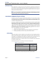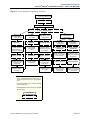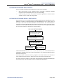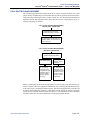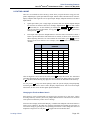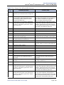
1
MITEL
Inter-Tel Axxess
®
®
Converged Communications Platform
Administrator Guide
Voice Mail Administrator Features
Quick Reference Guide for System,
Voice Mail, and Diagnostics
Administrator Features
You can use the voice mail administrator mailbox to program the following voice
mail features.
Accessing the Voice Mail Administrator Mailbox
1.
Dial the voice mail access number.
2.
Press * or say “Login” to identify yourself as a subscriber.
3.
Enter or say the administrator mailbox number.
4.
Enter the password, and then press #.
5.
Press 9 or say “Nine” to access the administrator menu.
The following are basic instructions for frequently used admin station and voice
mail administrator features.
System Administrator Features
You can use the admin station to program the following system features.
Setting the System in Day or Night Mode
Recording Broadcast Messages
1.
Access the administrator mailbox as described above.
2.
Press 1 or say “Broadcast Message” to select broadcast message.
3.
Record the message, and then press # to stop recording.
4.
Press # or say “Accept” to accept the message.
Performing Subscriber Mailbox Maintenance
Dial 9860. NIGHT MODE IS ON (or OFF) appears followed by THE
SYSTEM IS IN NIGHT MODE, if the system is in Night Mode. If the
system is in Day Mode, the display returns to the idle state.
Setting the System or Network Date and Time
1.
Dial 9800 (single node) or 9810 (multi-node). The programmed date
appears.
2.
Use the dialpad buttons to enter the month, day, and year. For example,
enter 020308 for February 3, 2008.
1.
Access the administrator mailbox as described above.
2.
Press 2 or say “Mailbox Maintenance.”
3.
3.
Enter or say the mailbox, extension ID, or group list number, and then
follow the prompts.
Use the dialpad buttons to enter the time in hours and minutes. For
example, enter 0900 for 9:00.
4.
If the system is set for 12-hour display format, SELECT AM OR PM (AM =
1 PM = 2) appears. Press 1 (or the AM menu button) for A.M. or press 2
(or the PM menu button) for P.M. SYSTEM DATE AND TIME UPDATED
appears.
Importing Fax Documents
1.
Using a fax machine, obtain dial tone, and then access the voice mail
administrator mailbox as described above.
2.
Press 4 or say “Import Fax.”
3.
Enter the fax document number, and then do one of the following:
•
•
4.
If the document number does not currently exist, press # or say
“Yes” if the number is correct, or press 3 or say “Re-enter” and reenter the number.
If the document currently exists, press # or say “Yes” to replace the
document, or press 3 or say “Re-enter” to enter another number.
When prompted, press Start on the fax machine.
Synchronizing Network Time
Dial 9811. NETWORK TIME SYNCHRONIZED appears.
Responding to Alarm Messages
1.
When a minor alarm indication appears, write down the alarm information.
2.
While on-hook, dial 9850 (Clear System Alarm) or dial 9851 (Clear
Network Alarm).
3.
Look up the alarm in the Administrator Guide and take the appropriate
action.
© Inter-Tel (Delaware), Inc. April 2008
Part No. 835.2461-6
Programming System Speed-Dial Numbers
Default Administrator Feature Codes
1.
Dial 9801. PROGRAM SYS SPD # <number range> appears.
2.
Enter the System Speed Dial location code (000–999 or 0000–4999).
ENTER NAME <current name> appears.
3.
Enter the name or leave the existing name. See the table below for
dialpad character descriptions.
Code
(U.S./Eur.)
9823
4.
Press # or the ACCEPT menu button. ENTER NUMBER appears.
5.
Enter the number, up to 48 digits, using one of the following methods:
•
•
6.
Press the REDIAL menu button to enter the last external number
dialed or saved.
Press # or the ACCEPT menu button to save the number. SYS SPD BIN
# <number> UPDATED appears.
Number of Times Button is Pressed in Alpha Mode
1
2
3
4
5
6
7
8
9
10
Automatic Diagnostics Delivery
On/Off
Code
(U.S./Eur.)
9866
Feature Name
Modem Enable
9851
Clear Network Alarm
9869
Modem Reset
9850
Clear System Alarm
9860
Night Ring On/Off
9982/9182
Compression On/Off
9981/9181
Compression Statistics
9900/9100
Use the dialpad to manually enter the number. In Numeric Mode,
you can press # to enter a hyphen (-) or press * to enter a colon (:).
If you make a mistake, press the backspace button to delete the last
characters entered.
Feature Name
9825
9932/9132
Periodic Diagnostics On/Off
Program Database
Diagnostics On/Off
9801
Program System Speed Dial
9862
Enable Network Day
9810
Set Network Date/Time
9861
Enable Network Night
9800
Set Time/Date
9867
Modem Disable
9811
Synchronize Network Time
Enabling or Disabling System Diagnostics Mode
While on-hook, enter the Diagnostics Mode feature code (9900 or 9100) to
enable/disable diagnostics mode. DIAGNOSTICS ON/OFF appears. Then enter
one of the following diagnostics feature codes shown below.
11
English/Spanish Characters
Japanese (Katakana) Characters1
Code
(U.S./Eur.)
Feature Name
Code
(U.S./Eur.)
1
-
&
(
)
1
A
I
U
E
O
a
9926/9126
Diagnostic - ASAI Snoop Off
9989/9189
2
A
B
C
’
2
KA
KI
KU
KE
KO
i
Diagnostic - Network
Unfreeze Zone – Sys. Hist.
9927/9127
Diagnostic - ASAI Snoop On
9972/9172
Diagnostic - Print Auxdata
3
D
E
F
!
3
SA
SHI
SU
SE
SO
u
9933/9133
9975/9175
Diagnostic - Print Mess. Log
4
G
H
I
*
4
TA
CHI
TSU
TE
TO
e
Diagnostic - Dump Extension
5
J
K
L
#
5
NA
NI
NU
NE
NO
o
9936/9136
Diagnostic - Dump Node Info
9976/9176
Diagnostic - Print Net. Log
9943/9143
Diagnostic - Heap Dump
9978/9178
Diagnostic - Query Node
Traffic
Button
Feature Name
6
M
N
O
ñ
6
HA
HI
FU
HE
HO
tsu
7
P
Q
R
S
7
MA
MI
MU
ME
MO
ya
9947/9147
Diagnostic - Heap Statistics
9928/9128
Diagnostic - Show Version
9948/9148
Diagnostic - ISDN View
9987/9187
Diagnostic - SIP View
9962/9162
Diagnostic - Major Reset
9910-9912/
9110-9112
Diagnostic - Spare 1–3
9945/9145
Diagnostic - Mark as Leaks
9974/9174
Diagnostic - System History
9946/9146
Diagnostic - Mark as Quies.
9983/9183
Diagnostic - View Displays
9964/9164
Diagnostic - Minor Reset
9973/9173
Seize Device
9939/9139
Diagnostic: Network Freeze
Zone - System Histories
9993/9193
System History Freeze
9963/9163
Diagnostic - Network Groups
9998/9198
System History Unfreeze
8
T
U
V
?
8
YA
YU
YO
.
,
yu
9
W
X
Y
Z
9
RA
RI
RU
RE
RO
yo
0
@
:
.
,
0
WA
WO
N
pa
ba
long
1. Japanese characters are supported on Inter-Tel Protocol (ITP) Mode display
endpoints only, and only if the Multilingual feature is enabled and Japanese is
installed as the secondary language.
Part Number
550.8001
®
®
INTER-TEL AXXESS CONVERGED
COMMUNICATIONS PLATFORM
ADMINISTRATOR GUIDE
Issue 11.0, May 2008
NOTICE
This Inter-Tel® Axxess® Administrator Guide is released by Inter-Tel (Delaware), Inc. as a guide for system
and voice mail administrators. It provides information necessary to properly administer the system.
The contents of this document reflect current Inter-Tel standards and are subject to revision or change without
notice. Some features or applications mentioned may require a future release and are not available in this
release. Future product features and applications are subject to availability and cost. Some features or
applications may require additional hardware and/or specific software.
The contents of this guide may include technical or other inaccuracies. Inter-Tel reserves the right to make
revisions or changes without prior notice. Software packages released after the publication of this guide will
be documented in addenda to the guide or succeeding issues of the guide.
For sales, service, or technical support,
contact your local authorized Inter-Tel provider.
If you have any questions or comments regarding this guide or other technical documentation, contact the
Technical Publications Department (USA) at:
[email protected]
Inter-Tel® is a registered trademark of Inter-Tel (Delaware), Incorporated.
Mitel® is a registered trademark of Mitel Networks Corporation.
All other trademarks mentioned in this document are the property of their respective owners, including Mitel Networks Corporation and Inter-Tel (Delaware), Incorporated. All rights reserved.
© 1993-2008 Inter-Tel (Delaware), Incorporated
Personal use of this material is permitted. However, permission to reprint/republish this material for advertising or promotional
purposes or for creating new collective works for resale or redistribution to servers or lists, or to reuse any copy righted component
of this work in other works must be obtained from Inter-Tel (Delaware), Inc.
Product Disposal Instructions
This symbol indicates that the product is classified as electrical or electronic equipment and
should not be disposed of with other commercial or household waste at the end of its working life. For appropriate disposal and recycling instructions, contact your local recycling
authority or Inter-Tel provider.
The Waste of Electrical and Electronic Equipment (WEEE) Directive (2002/96/EC) was established by the European Union to minimize negative impact on the environment, control hazardous substances, and curtail landfill expansion by using
the best available recovery and recycling techniques.
Table of Contents
Inter-Tel® Axxess® Administrator Guide — Issue 11.0, May 2008
Table of Contents
CONTENTS
PAGE
Safety Instructions
ix
Regulatory Notices
ix
Network Security Statement
ix
V11.0 New Features
xi
Overview
1
Introduction . . . . . . . . . . . . . . . . . . . . . . . . . . . . . . . . . . . . . . . . . . . . . . . . . . . . . . . . . . . . . . 2
Converged Communications Platform . . . . . . . . . . . . . . . . . . . . . . . . . . . . . . . . . . . . . . . . 2
Voice Processing Systems . . . . . . . . . . . . . . . . . . . . . . . . . . . . . . . . . . . . . . . . . . . . . . . . . . . 5
Administrator Procedures
11
Introduction . . . . . . . . . . . . . . . . . . . . . . . . . . . . . . . . . . . . . . . . . . . . . . . . . . . . . . . . . . . . . 12
System Administrator Procedures . . . . . . . . . . . . . . . . . . . . . . . . . . . . . . . . . . . . . . . . . . . 13
Voice Mail Administrator Procedures . . . . . . . . . . . . . . . . . . . . . . . . . . . . . . . . . . . . . . . . 52
Administrator Programming Planning Sheets . . . . . . . . . . . . . . . . . . . . . . . . . . . . . . . . . 67
System Hardware
73
Introduction . . . . . . . . . . . . . . . . . . . . . . . . . . . . . . . . . . . . . . . . . . . . . . . . . . . . . . . . . . . . . 75
Station Instruments . . . . . . . . . . . . . . . . . . . . . . . . . . . . . . . . . . . . . . . . . . . . . . . . . . . . . . . 76
Optional System Equipment. . . . . . . . . . . . . . . . . . . . . . . . . . . . . . . . . . . . . . . . . . . . . . . 109
System Features
111
Access to the Features . . . . . . . . . . . . . . . . . . . . . . . . . . . . . . . . . . . . . . . . . . . . . . . . . . . . 116
Attendant Stations . . . . . . . . . . . . . . . . . . . . . . . . . . . . . . . . . . . . . . . . . . . . . . . . . . . . . . . 129
Hunt Groups. . . . . . . . . . . . . . . . . . . . . . . . . . . . . . . . . . . . . . . . . . . . . . . . . . . . . . . . . . . . 132
Trunk Features. . . . . . . . . . . . . . . . . . . . . . . . . . . . . . . . . . . . . . . . . . . . . . . . . . . . . . . . . . 153
Inter-Tel Endpoint Features . . . . . . . . . . . . . . . . . . . . . . . . . . . . . . . . . . . . . . . . . . . . . . . 172
Multilingual Capability . . . . . . . . . . . . . . . . . . . . . . . . . . . . . . . . . . . . . . . . . . . . . . . . . . . 180
Page v
Table of Contents
Inter-Tel® Axxess® Administrator Guide — Issue 11.0, May 2008
CONTENTS
PAGE
Intercom Calls . . . . . . . . . . . . . . . . . . . . . . . . . . . . . . . . . . . . . . . . . . . . . . . . . . . . . . . . . . 184
Call Logging . . . . . . . . . . . . . . . . . . . . . . . . . . . . . . . . . . . . . . . . . . . . . . . . . . . . . . . . . . . . 190
Inter-Station Messages . . . . . . . . . . . . . . . . . . . . . . . . . . . . . . . . . . . . . . . . . . . . . . . . . . . 194
Off-Hook Voice Announce (OHVA) . . . . . . . . . . . . . . . . . . . . . . . . . . . . . . . . . . . . . . . . . 199
Outside Calls . . . . . . . . . . . . . . . . . . . . . . . . . . . . . . . . . . . . . . . . . . . . . . . . . . . . . . . . . . . 201
Placing Calls On Hold . . . . . . . . . . . . . . . . . . . . . . . . . . . . . . . . . . . . . . . . . . . . . . . . . . . . 211
Call Waiting . . . . . . . . . . . . . . . . . . . . . . . . . . . . . . . . . . . . . . . . . . . . . . . . . . . . . . . . . . . . 214
Call Transfer . . . . . . . . . . . . . . . . . . . . . . . . . . . . . . . . . . . . . . . . . . . . . . . . . . . . . . . . . . . 216
Call Screening . . . . . . . . . . . . . . . . . . . . . . . . . . . . . . . . . . . . . . . . . . . . . . . . . . . . . . . . . . 219
Reverse Transfer . . . . . . . . . . . . . . . . . . . . . . . . . . . . . . . . . . . . . . . . . . . . . . . . . . . . . . . . 221
Conference Calls . . . . . . . . . . . . . . . . . . . . . . . . . . . . . . . . . . . . . . . . . . . . . . . . . . . . . . . . 222
Record-A-Call . . . . . . . . . . . . . . . . . . . . . . . . . . . . . . . . . . . . . . . . . . . . . . . . . . . . . . . . . . 227
Agent Help . . . . . . . . . . . . . . . . . . . . . . . . . . . . . . . . . . . . . . . . . . . . . . . . . . . . . . . . . . . . . 229
System Forwarding . . . . . . . . . . . . . . . . . . . . . . . . . . . . . . . . . . . . . . . . . . . . . . . . . . . . . . 232
Call Forwarding. . . . . . . . . . . . . . . . . . . . . . . . . . . . . . . . . . . . . . . . . . . . . . . . . . . . . . . . . 239
Speed Dialing . . . . . . . . . . . . . . . . . . . . . . . . . . . . . . . . . . . . . . . . . . . . . . . . . . . . . . . . . . . 243
Intercom, Speed Dial, and Feature Code Directory . . . . . . . . . . . . . . . . . . . . . . . . . . . . 251
Intelligent Directory Search (IDS) . . . . . . . . . . . . . . . . . . . . . . . . . . . . . . . . . . . . . . . . . . 253
House Phone . . . . . . . . . . . . . . . . . . . . . . . . . . . . . . . . . . . . . . . . . . . . . . . . . . . . . . . . . . . . 259
Redialing. . . . . . . . . . . . . . . . . . . . . . . . . . . . . . . . . . . . . . . . . . . . . . . . . . . . . . . . . . . . . . . 260
Redirect Call. . . . . . . . . . . . . . . . . . . . . . . . . . . . . . . . . . . . . . . . . . . . . . . . . . . . . . . . . . . . 263
Paging . . . . . . . . . . . . . . . . . . . . . . . . . . . . . . . . . . . . . . . . . . . . . . . . . . . . . . . . . . . . . . . . . 264
Remove from Paging . . . . . . . . . . . . . . . . . . . . . . . . . . . . . . . . . . . . . . . . . . . . . . . . . . . . . 265
Do-Not-Disturb . . . . . . . . . . . . . . . . . . . . . . . . . . . . . . . . . . . . . . . . . . . . . . . . . . . . . . . . . 265
Do-Not-Disturb Override . . . . . . . . . . . . . . . . . . . . . . . . . . . . . . . . . . . . . . . . . . . . . . . . . 269
Remote Feature Programming . . . . . . . . . . . . . . . . . . . . . . . . . . . . . . . . . . . . . . . . . . . . . 269
Default Station . . . . . . . . . . . . . . . . . . . . . . . . . . . . . . . . . . . . . . . . . . . . . . . . . . . . . . . . . . 273
Hookflash/Recall . . . . . . . . . . . . . . . . . . . . . . . . . . . . . . . . . . . . . . . . . . . . . . . . . . . . . . . . 274
Reminder Messages . . . . . . . . . . . . . . . . . . . . . . . . . . . . . . . . . . . . . . . . . . . . . . . . . . . . . . 274
Record Keeping and Maintenance Features . . . . . . . . . . . . . . . . . . . . . . . . . . . . . . . . . . 277
Audio Diagnostics Feature . . . . . . . . . . . . . . . . . . . . . . . . . . . . . . . . . . . . . . . . . . . . . . . . 284
Phantom Devices . . . . . . . . . . . . . . . . . . . . . . . . . . . . . . . . . . . . . . . . . . . . . . . . . . . . . . . . 287
Page vi
Inter-Tel® Axxess® Administrator
CONTENTS
Voice Processing Features
Table of Contents
Guide — Issue 11.0, May 2008
PAGE
289
Introduction . . . . . . . . . . . . . . . . . . . . . . . . . . . . . . . . . . . . . . . . . . . . . . . . . . . . . . . . . . . . 291
Automated Attendant . . . . . . . . . . . . . . . . . . . . . . . . . . . . . . . . . . . . . . . . . . . . . . . . . . . . 291
Automatic Fax Detection. . . . . . . . . . . . . . . . . . . . . . . . . . . . . . . . . . . . . . . . . . . . . . . . . . 295
Automatic Speech Recognition . . . . . . . . . . . . . . . . . . . . . . . . . . . . . . . . . . . . . . . . . . . . . 296
Call Routing Announcement . . . . . . . . . . . . . . . . . . . . . . . . . . . . . . . . . . . . . . . . . . . . . . 297
Directories. . . . . . . . . . . . . . . . . . . . . . . . . . . . . . . . . . . . . . . . . . . . . . . . . . . . . . . . . . . . . . 300
EM Directories . . . . . . . . . . . . . . . . . . . . . . . . . . . . . . . . . . . . . . . . . . . . . . . . . . . . . . . . . . 304
E-Mail Reader . . . . . . . . . . . . . . . . . . . . . . . . . . . . . . . . . . . . . . . . . . . . . . . . . . . . . . . . . . 307
Fax-On-Demand . . . . . . . . . . . . . . . . . . . . . . . . . . . . . . . . . . . . . . . . . . . . . . . . . . . . . . . . 308
Record-A-Call . . . . . . . . . . . . . . . . . . . . . . . . . . . . . . . . . . . . . . . . . . . . . . . . . . . . . . . . . . 310
Scheduled Time-Based Application Routing (STAR). . . . . . . . . . . . . . . . . . . . . . . . . . . 311
SMDR Information Storage and Retrieval . . . . . . . . . . . . . . . . . . . . . . . . . . . . . . . . . . . 313
Voice Mail . . . . . . . . . . . . . . . . . . . . . . . . . . . . . . . . . . . . . . . . . . . . . . . . . . . . . . . . . . . . . . 314
Subscriber Features. . . . . . . . . . . . . . . . . . . . . . . . . . . . . . . . . . . . . . . . . . . . . . . . . . . . . . 320
Unified Messaging . . . . . . . . . . . . . . . . . . . . . . . . . . . . . . . . . . . . . . . . . . . . . . . . . . . . . . . 322
Unified Messaging Open Standards Edition . . . . . . . . . . . . . . . . . . . . . . . . . . . . . . . . . . 322
Voice Processing Prompts
323
Voice Processing Systems . . . . . . . . . . . . . . . . . . . . . . . . . . . . . . . . . . . . . . . . . . . . . . . . . 324
Automatic Speech Recognition (ASR) . . . . . . . . . . . . . . . . . . . . . . . . . . . . . . . . . . . . . . . 324
Default ASR and Non-ASR Voice Prompts . . . . . . . . . . . . . . . . . . . . . . . . . . . . . . . . . . . 324
Default Feature Codes
353
Index
355
Page vii
Inter-Tel® Axxess® Administrator
Safety Instructions
Guide — Issue 11.0, May 2008
Safety Instructions
For basic installation guidelines necessary for the proper and safe functioning of this equipment, refer to the Important Safety Instructions (part number 835.3209) packaged with the system, included on the product software CD, and posted on the Inter-Tel® edGe Online Manuals
and Guides (www.inter-tel.com/techpublications) Web site.
Read and follow all information contained in the Important Safety Instructions docuNOTE ment before attempting to install or use this product. Only trained, qualified service
personnel shall install or maintain this product.
Regulatory Notices
For regulatory information for U.S., Canada, and Europe, refer to the Regulatory Notices section in the Important Safety Instructions (part number 835.3209) packaged with the system,
included on the product software CD, and posted on the Inter-Tel edGe Online Manuals and
Guides (www.inter-tel.com/techpublications) Web site.
Network Security Statement
Although no telecommunications system or data network is entirely secure, as long as the
appropriate security measures are put in place and properly maintained by both the customer
and the installing company, the Axxess® system architecture and its associated server-based
applications are substantially secure against unauthorized access to the customer's data network via the telecommunications system. Appropriate security measures include, but are not
limited to, the proper implementation of user/administrative accounts, passwords, firewalls,
Network Address Translation (NAT), access control lists, virus protection, security updates,
etc. and the proper maintenance of access points/programs and their respective accounts/passwords.
Page ix
V11.0 New Features
Inter-Tel® Axxess® Administrator Guide — Issue 11.0, May 2008
V11.0 New Features
For those individuals who are already familiar with the Issue 10.0 Inter-Tel Axxess Administrator Guide (part number 550.8001), the following new items are introduced in the version 11.0
release. Throughout the guide, “change bars” like the one next to the left of this paragraph
have been placed in the margins to indicate any new or revised information since the Issue 10.0
Guide.
FEATURES AND ENHANCEMENTS IN V11.0
The following new features and enhancements are provided with v11.0:
•
Caller ID Forwarding: A new station flag for Caller ID, Propagate Original Caller ID
on Transfer, is added which affects Inter-Tel endpoint displays when calls are forwarded. For details, see “Inter-Tel Endpoint Displays” on page 154.
•
Phantom Device Enhancements: Phantom devices are now fully functional virtual
devices on the system. For details, see “Phantom Devices” on page 287.
ADDITIONAL SYSTEM CHANGES
The following changes are not related to the v11.0 new features and enhancements:
•
New Enhanced IP Resource Cards: The Inter-Tel Axxess Internet Protocol Resource
Card (IPRC) “enhanced” daughter card offers new technology for echo cancellation on
all calls routed through the IPRC. See page 77.
•
New SIP Gateways: Inter-Tel now supports the following SIP gateways:
—
Quintum® AFT 400 SIP gateway
—
AudioCodes™ MP-114 SIP gateway
See “SIP Gateway” on page 103 and “IP Devices and Local Loop Support” on
page 168.
Page xi
V11.0 New Features
Inter-Tel® Axxess® Administrator Guide — Issue 11.0, May 2008
•
•
Page xii
Enterprise® Messaging (EM) Enhancements: The following new EM features are to
be introduced in EM v2.1.
—
Option Swap — 7 and 9 Keys: EM provides a swap feature whereby the 7 and 9
digit operations can be reversed. Currently, the 7 digit is used for save and the 9
digit is used for delete. The swap feature allows the 7 digit to be used for delete
and the 9 digit to be used for save just like the functionality operated by the cell
phone voice mail systems. You can change this option for users through the Voice
Mail Flowchart in the back of this guide under Personal Options. Refer to the
Enterprise Messaging Installation and Maintenance Manual (part no. 780.8006)
for details about this feature. Also, see the end of Table 37 for the new new voice
prompts that have been added for this feature (see prompt numbers 947 through
953 beginning on page 351).
—
Voice Profile for Internet Mail (VPIM) Networking: VPIM allows EM to communicate with other voice processing systems. VPIM networking requires the
Inter-Tel Messaging IP Networking premium feature. See “Voice Processing Systems” on page 5.
Unified Messaging (UM) versions 2.2 (VPU) and 2.3 (EM): Have reached their end
of sale are no longer supported after April 30, 2008. Inter-Tel recommends that current
UM v2.2 and v2.3 installations upgrade to UM Open Standards Edition (OSE). See
“Unified Messaging Open Standards Edition” on page 322 for more information.
Inter-Tel® Axxess® Administrator
Overview
Guide — Issue 11.0, May 2008
Overview
CONTENTS
PAGE
Introduction . . . . . . . . . . . . . . . . . . . . . . . . . . . . . . . . . . . . . . . . . . . . . . . . . . . . . . . . . . . . . . 2
Converged Communications Platform . . . . . . . . . . . . . . . . . . . . . . . . . . . . . . . . . . . . . . . . 2
Networking . . . . . . . . . . . . . . . . . . . . . . . . . . . . . . . . . . . . . . . . . . . . . . . . . . . . . . . . . . . . 2
Inter-Tel Software Licensing . . . . . . . . . . . . . . . . . . . . . . . . . . . . . . . . . . . . . . . . . . . . . . 3
“Endpoints” and “Phones” . . . . . . . . . . . . . . . . . . . . . . . . . . . . . . . . . . . . . . . . . . . . . . . . 4
System Administrator Duties . . . . . . . . . . . . . . . . . . . . . . . . . . . . . . . . . . . . . . . . . . . . . . 5
Voice Processing Systems . . . . . . . . . . . . . . . . . . . . . . . . . . . . . . . . . . . . . . . . . . . . . . . . . . . 5
Voice Processing System Applications. . . . . . . . . . . . . . . . . . . . . . . . . . . . . . . . . . . . . . . 6
Voice Mail Networking . . . . . . . . . . . . . . . . . . . . . . . . . . . . . . . . . . . . . . . . . . . . . . . . . . 8
Voice Mail Administrator Duties . . . . . . . . . . . . . . . . . . . . . . . . . . . . . . . . . . . . . . . . . . . 9
Page 1
Overview
Inter-Tel® Axxess® Administrator Guide — Issue 11.0, May 2008
INTRODUCTION
This Administrator’s Guide provides all of the information an administrator should need to
know about the system hardware and features, and it gives detailed instructions on their use.
Refer to the user guide provided with each endpoint for simplified instructions on using endpoint and voice mail system features.
NOTE: Inter-Tel recommends provisioning each system with an endpoint that has a 6-line display to allow an Administrator to program selected system data, act as the Attendant for unsupervised CO recalls, receive system alarm messages, etc.
CONVERGED COMMUNICATIONS PLATFORM
The Inter-Tel Axxess ® Converged Communications Platform is a state-of-the-art, digital,
voice/data, hybrid communications system. As a hybrid system, it incorporates many of the
user-friendly features of key systems with many of the expanded features and flexibility of private branch exchange (PBX) systems.
The system is designed to meet the needs of growing businesses. In fact, the system’s unique
digital signal processor (DSP) structure allows it to be easily adapted and expanded as business
communication needs change, especially with the Caller ID, Automatic Number Identification
(ANI), Dialed Number Identification Service (DNIS), and Integrated Services Digital Network
(ISDN) features. The modular design makes the system easy to install and service. And, the
programmable features provide an abundance of user-friendly applications to meet each customer’s needs. Highlights of the system’s design include:
•
Advanced microprocessor technology
•
Modular, easily replaceable hardware with add-on capabilities for optional features
•
Flexible programming to customize many system and station features
NETWORKING
With system software versions 5.0 and later, you can connect two or more telephone systems to
form a network that provides a seamless interface between the systems. To the user, the network appears as one integrated system. With few exceptions, the user can perform all of the
functions across the network that can be performed within a single telephone system.
In this guide, all references to a “network” mean two or more connected systems. Each system
in a network is called a “node.”
The maximum capacities for networking are listed in the following table:
Table 1. Network Capacities
FEATURE/DEVICES
System Nodes per network
CAPACITY
99
Local devices per node
1792*
Off-node devices per node
25,000
Devices per network
40,000
* The maximum number of stations and trunks that can be installed is limited by
the number of voice channels and/or system memory resources available.
Page 2
Introduction
Inter-Tel® Axxess® Administrator
Overview
Guide — Issue 11.0, May 2008
INTER-TEL SOFTWARE LICENSING
The Software License folder displays the licenses currently uploaded to the system. The features common to all licenses are displayed in this folder along with the value for each feature
according to the current software license. This folder is read-only. If there is no license loaded
or the current license on the system is invalid, and if connected to Database Programming in
remote mode, then the fields will display with a red “X” over them. The available software
license features are listed in Table 2 below.
Table 2. Available Software License Features
FIELD
DESCRIPTION
ACD Hunt Group
Indicates whether or not the ACD Hunt Groups software
license is uploaded to the system.
Advanced CO Interfaces
Indicates whether or not the Advanced CO Interfaces
software license is uploaded to the system.
Agent Help
Indicates whether or not the Agent Help software
license is uploaded to the system.
Analog Voice Mail Hunt Group
Indicates whether or not the Analog Voice Mail Hunt
Group software license is uploaded to the system.
Automatic Route Selection
Indicates whether or not the Automatic Route Selection
software license is uploaded to the system.
Category A Endpoints
Indicates how many Category A endpoint licenses are
uploaded to the system.
Category B Endpoints
Indicates how many Category B endpoint licenses are
uploaded to the system.
CPS Redundancy
Indicates whether or not the CPS Redundancy software
license is uploaded to the system.
Desktop Interface
Indicates whether or not the Desktop Interface software
license is uploaded to the system.
Directories
Indicates whether or not the Directories software license
is uploaded to the system.
Inter-Tel Messaging IP Networking
Indicates whether or not the Inter-Tel Messaging IP Networking software license is uploaded to the system.
IP Networking
Indicates how many IP networking licenses are
uploaded to the system.
Multilingual Support
Indicates whether or not the Multilingual Support software license is uploaded to the system.
Remote Automatic Call Distribution Hunt Groups
Indicates whether or not the Remote Automatic Call Distribution Hunt Groups software license is uploaded to
the system.
SIP Trunks
Indicates how many SIP trunk licenses are uploaded to
the system.
System Forwarding
Indicates whether or not the System Forwarding software license is uploaded to the system.
System OAI Events
Indicates whether or not the System OAI Events software license is uploaded to the system.
System OAI Third Party Call Control
Indicates whether or not the System OAI Third Party
Call Control software license is uploaded to the system.
Inter-Tel Software Licensing
Page 3
Overview
Inter-Tel® Axxess® Administrator Guide — Issue 11.0, May 2008
Table 2. Available Software License Features (Continued)
FIELD
DESCRIPTION
Uniform Call Distribution Hunt
Groups
Indicates whether or not the Uniform Call Distribution
Hunt Groups software license is uploaded to the system.
Voice Processor AMIS Networking
Indicates whether or not the Voice Processor AMIS Networking software license is uploaded to the system.
“ENDPOINTS” AND “PHONES”
As digital, wireless, and computerized communication methods have evolved, the language of
telecommunications has had to change to keep pace. Not long ago, voice and modem-encoded
text were communicated from one telephone instrument to another across a global network of
copper wire, optical fiber, microwave antennas, and satellites. More recently, however, the
development of the Internet and of World Wide Web (www) sites have introduced a multimedia dimension to information and made it all more readily accessible through computer networking. As this evolution has occurred, new words and meanings have been introduced to
describe the new methods and equipment used for communicating.
Telephone systems that once provided only audio phone service to consumers have become
“communication platforms” that support many devices that people can use for personal and
business communication. Phones now share communciation space with personal digital assistants (PDA), with wireless phones capable of text messaging, taking photos, and recording
video, with fax machines that transmit and receive messages across Internet Protocol (IP), and
with “soft” phones that are displayed and used from computer screens.
Computer Science Roots
When referring to communication protocols in computer science, the term “endpoint”
describes an entity on one end of a Transport Layer connection. The Transport Layer is the
Transmission Control Protocol/Internet Protocol (TCP/IP) layer in the Open Systems Interconnect (OSI) network model. Utilizing the TCP/IP layer standard, Internet servers send and
receive packets of data across the World Wide Web.
Usage in This Manual
This manual uses the term “endpoint” to describe the entire category of devices that the InterTel Axxess family of products supports. In this context, digital and IP phones are endpoints, as
are data modules, fax machines, computer telephony (CT) gateways, Single-Line Adapters
(SLA), IP Single-Line Adapters (IP-SLA), and answering machines.
And, to promote clear communication and understanding, commonly accepted names of endpoints are used as appropriate. In particular, desktop IP endpoints are also referred to as IP
phones. Digital endpoints are also referred to as digital phones. Wireless endpoints are also
referred to as wireless phones. And, analog single line endpoints are also referred to as single
line phones or single line sets.
NOTE: In the manual and in Database Programming, a phone may also be called a “station”
when reference to the phone and its environment are intended. Or, it may be called “device” in
the most general sense.
Page 4
“Endpoints” and “Phones”
Inter-Tel® Axxess® Administrator
Overview
Guide — Issue 11.0, May 2008
SYSTEM ADMINISTRATOR DUTIES
As a System Administrator, you can provide the following services:
•
Place the local telephone system or other systems in the network in night or day mode.
•
Set the date and time of the local system.
•
Set the network date and time and re-synchronize clocks in the network.
•
Make database changes (see page 16 for a list of programming areas).
•
Program System Speed Dial numbers on the local system.
•
Receive and clear displayed system and network alarms.
•
Use diagnostic mode features to:
—
Freeze and unfreeze database history on the local system or other systems in the
network.
—
Print error logs.
—
Seize specific devices for troubleshooting purposes.
—
Report audio problems to your installer/technician.
Any Inter-Tel endpoint can be designated as a system administrator station through Database
Programming. It is strongly recommended that you program display endpoints as administrator
stations to facilitate programming and manage alarms. Administrator features are described in
detail, beginning on page 13.
NOTE: Single line sets cannot be programmed as administrator stations.
VOICE PROCESSING SYSTEMS
The Axxess platform supports the following voice processing systems:
•
Voice Processing Unit: The Voice Processing Unit (VPU) runs on either the Windows
NT or Windows 2000 operating systems. The VPU system is installed on an IBM-compatible PC that is connected to the Inter-Tel system to provide integrated voice processing features such as Voice Mail, Directories, Record-A-Call, etc.
•
Embedded Voice Mail Card: The Embedded Voice Mail Card (EVMC) runs on the
OS/2 or the Linux operating system. The EVMC provides voice processing for small to
medium-sized systems. It can support 32, 64, or 200 mailboxes, depending on the configuration. The EVMC’s 2.0 Gigabyte hard drive will support up to 180 hours of voice
messages. The EVMC supports AMIS networking and database saves to a zip or floppy
drive. It does not support Fax-On-Demand and Unified Messaging.
•
Enterprise® Messaging: Enterprise Messaging (EM) runs on the Windows 2000 operating system. EM is an external voice processing system. EM unifies communication
and messaging by providing access to voice mail, fax, and e-mail messages in the user’s
mailbox. In addition, EM provides automatic speech recognition capabilities and builtin Unified Messaging features. EM supports Voice Profile for Internet Mail (VPIM)
networking. For detailed information about EM, see the Enterprise Messaging Installation and Maintenance Manual (part no. 780.8006).
System Administrator Duties
Page 5
Overview
Inter-Tel® Axxess® Administrator Guide — Issue 11.0, May 2008
VOICE PROCESSING SYSTEM APPLICATIONS
Axxess platform voice processing systems support several voice processing system applications. Depending on your site’s voice processing system, equipment, and licensing, you may
have access to one or more of the following voice processing system features:
•
Automated Attendant: Automated Attendant is a programmable feature that provides
automated call answering services. Calls can transfer, forward, or directly ring in to
Automated Attendant. When Automated Attendant answers a call, it plays a recording
that gives dialing instructions. After hearing the recording, or at any time while it is
playing, the caller may dial an extension or mailbox number. For more information
about the Automated Attendant feature, see page 291.
•
Automated Attendant Recall Destination: If a call that is transferred by Automated
Attendant is not answered before the Transfer Voice Processor timer expires, the call
recalls the Automated Attendant Recall Destination. The Recall Destination announces
that the station is unavailable and allows the caller to leave a message if the station has
an associated mailbox, or to dial another extension. For more information about the
Automated Attendant Recall Destination, see page 293.
•
Automatic Fax Detection: With Automatic Fax Detection, Call Routing Announcement applications and mailboxes can be programmed to automatically route incoming
fax calls to a specified extension or to an e-mail address. For more information about
the Automatic Fax Detection, see page 295.
•
Automatic Speech Recognition (ASR): The EM system supports Automatic Speech
Recognition (ASR), which is a licensed feature. ASR can be enabled on many levels
within the voice processing system. Using EM, subscribers can issue spoken commands
to navigate the voice mail menus. Subscribers and non-subscribers can also use spoken
commands to search the voice mail directory, and to navigate automated attendant
menus and call routing applications. When ASR resources are not available, subscribers
and non-subscribers can also perform these tasks by pressing the appropriate dialpad
digits when prompted by the system. For more information about ASR, see page 296.
•
Call Routing Announcement: Call Routing Announcements can be used two ways. A
Call Routing Announcement application can be used in place of a playback device. The
playback device function is especially useful for programming hunt group announcement and overflow stations. When called, the Call Routing Announcement application
will play a recording and then hang up.
The Call Routing Announcement application can also use Digit Translation, which
allows the caller to press a single digit for access to a mailbox, a fax-on-demand function, or a station or hunt group that has an associated mailbox or extension ID. Digit
Translation can be programmed for each digit 0-9, #, and *, plus a Timeout that is used
when the caller does not enter a digit. Each digit can lead to a “digit translation node”
that has its own digit translation values. This layered Call Routing Announcement digit
translation creates a “tree” of programmable digit translation nodes. For more information about Call Routing Announcements, see page 297.
•
Page 6
Directory Services: Directory Services provide callers with a list of mailboxes and
extension IDs that can be accessed through voice mail or the automated attendant. The
Directory feature is available in each of the voice processing systems, but varies
slightly in the Enterprise Messaging (EM) system. For information about using directories, see page 300. For information about using directories in EM, see page 304.
Voice Processing System Applications
Inter-Tel® Axxess® Administrator
Overview
Guide — Issue 11.0, May 2008
•
E-Mail Reader: E-Mail Reader is a licensable feature available with the EM voice processing system that provides users with advanced mailbox capabilities through Text-ToSpeech (TTS) technology. When E-Mail Reader is enabled for a mailbox, the user can
access voice mail, e-mail, and fax messages by logging in to his or her mailbox. E-Mail
Reader announces the message envelope, and can also “read” the text in the body of email messages. E-Mail Reader users also have access to additional message options,
which vary based on the media type. For more information about E-Mail Reader, see
page 307.
•
Fax-On-Demand: The Fax-On-Demand feature is a specially programmed Call Routing Announcement application that uses digit translation to allow callers to select the
documents they want to have faxed to them. With Fax-On-Demand, callers can use a
DTMF endpoint to request one or more documents from the company’s fax library, the
library that is also used in the Unified Messaging faxing feature. When the request is
completed, the voice processing system places a call to the caller’s fax machine to
deliver the requested documents. For more information about the Fax-On-Demand feature, see page 308.
•
Record-A-Call: This feature allows a station user to record a call-in-progress in a voice
mailbox message. When a station user enters the Record-A-Call feature code, the system places a call to the station’s assigned Record-A-Call application. When the application answers, the system sets up a conference call with the station’s Record-A-Call
mailbox. If programmed, the mailbox plays a greeting to indicate that the recording is
in progress. For more information about the Record-A-Call feature, see page 310.
•
Scheduled Time-based Application Routing (STAR): STAR enhances the programmability of the voice mail application greetings. With STAR, applications can be programmed to play alternative greetings for holidays and weekends. A STAR application
is a table of up to 20 entries, that serve as a “routing table.” The routing table tells the
voice processing system which application will be used based on day and time information in the table. The identified applications are programmed to play the greetings. The
STAR feature only routes the call to the right application. For more information about
STAR, see page 311.
•
Station Message Detail Recording (SMDR) Information Storage: SMDR information can be stored on the voice processing system’s hard disk and then processed using
call record sorting software. For more information about STAR, see page 313.
•
Voice Mail and Message Notification Retrieval: Voice Mail handles all calls that are
directed to voice mail (other than through the Message Notification/Retrieval application) by subscribers and non-subscribers. If your system is using EM and E-Mail
Reader is enabled for the mailbox, the user has access to advanced messaging features
using his or her advanced mailbox. With Voice Mail, callers hear the main company
greeting, followed by a menu of available options. Message Notification/Retrieval provides voice mail message notification and quick mailbox access. For more information
about Voice Mail and Message Notification Retrieval, see (page 314).
•
Unified Messaging: The Unified Messaging (UM) feature links the voice processing
system with e-mail and/or provides outgoing fax capabilities. Depending on which
voice processing system that you are using, you may have UM version 2.2 or 2.3. For
more information about UM, see page 322.
Voice Processing System Applications
Page 7
Overview
Inter-Tel® Axxess® Administrator Guide — Issue 11.0, May 2008
VOICE MAIL NETWORKING
A Voice Processing Unit (VPU) or Enterprise Messagin (EM) unit can be installed on any or
all nodes in the phone network. These Voice Processing systems can also be networked
together to allow a caller to leave a message on the local Voice Processing system for a mailbox located on another Voice Processing system in the network.
The maximum capacities of the network are listed in Table 3:
Table 3. Networked Voice Processing Systems Capacities
FEATURE/DEVICES
Voice Processing Units per network
Mailboxes and/or Extension IDs per Voice Processing
node
Local:
Off-Node:
VP UNIT
CAPACITY
EM UNIT
CAPACITY
100a
200a
10000b
10000b
CPC: 10000
512 CPS: 10000
1024/ATMCPS: 25000
CPC: 1000
512 CPS: 10000
1024/ATMCPS: 25000
40
24 (for Base I)
32 (for Base II)b
Applicationsc per node
1000
1000
Group Lists per node
Members per group list
1000
1500
500
1000
Remote Message Notification Numbers per mailbox
18
18
Audiotex Recordings per node
500
500d
Message Notification/Retrieval Applications per node
1
1
System Passwords per node
4
10
Time Slot Groups per node
10
10
System Audio Interface Ports per node
a This
is the maximum number of nodes supported by the software. System traffic may limit the actual number of nodes that can be supported without affecting system performance.
Page 8
b
This is the maximum number of mailboxes supported by the NT-based software.
c
Applications include Call Routing Announcements, STAR applications, Record-A-Call, etc. .
d
The number of programmed custom recordings is only limited by the size of the local hard disk.
Voice Mail Networking
Inter-Tel® Axxess® Administrator
Overview
Guide — Issue 11.0, May 2008
VOICE MAIL ADMINISTRATOR DUTIES
As the voice mail administrator, you can use special features that are not provided to other
voice mail users (subscribers). The mailbox designated as the administrator mailbox has all of
the standard subscriber features (which can be found in the appropriate endpoint user guide),
plus the ability to do the following:
•
Record a broadcast message
•
Perform mailbox and group list maintenance
•
Create and select custom Audiotex recordings (voice mail company greetings, auto
attendant recordings, call routing announcements, and hunt group overflow and
announcement station recordings)
•
Import fax documents
•
Customize voice mail prompts
Voice mail administrator features are described in detail on page 52.
Voice Mail Administrator Duties
Page 9
Administrator Procedures
Inter-Tel Axxess Administrator Guide — Issue 11.0, May 2008
®
®
Administrator Procedures
CONTENTS
PAGE
Introduction. . . . . . . . . . . . . . . . . . . . . . . . . . . . . . . . . . . . . . . . . . . . . . . . . . . . . . . . . . . . . . . . . 12
System Administrator Procedures . . . . . . . . . . . . . . . . . . . . . . . . . . . . . . . . . . . . . . . . . . . . . . 13
Placing the System in Night Mode . . . . . . . . . . . . . . . . . . . . . . . . . . . . . . . . . . . . . . . . . . . . 13
Placing Nodes in Day or Night Mode . . . . . . . . . . . . . . . . . . . . . . . . . . . . . . . . . . . . . . . . . . 13
Setting System Date and Time. . . . . . . . . . . . . . . . . . . . . . . . . . . . . . . . . . . . . . . . . . . . . . . . 14
Setting Network Date and Time . . . . . . . . . . . . . . . . . . . . . . . . . . . . . . . . . . . . . . . . . . . . . . 15
Synchronizing Network Time . . . . . . . . . . . . . . . . . . . . . . . . . . . . . . . . . . . . . . . . . . . . . . . . 16
Programming the Database Using an Administrator’s Station . . . . . . . . . . . . . . . . . . . . . . . 16
Station Programming . . . . . . . . . . . . . . . . . . . . . . . . . . . . . . . . . . . . . . . . . . . . . . . . . . . 18
System Programming . . . . . . . . . . . . . . . . . . . . . . . . . . . . . . . . . . . . . . . . . . . . . . . . . . . 24
Trunk Programming . . . . . . . . . . . . . . . . . . . . . . . . . . . . . . . . . . . . . . . . . . . . . . . . . . . . 30
Programming System Speed Dial Numbers . . . . . . . . . . . . . . . . . . . . . . . . . . . . . . . . . . . . . 38
Programming and Using DSS/BLF Buttons . . . . . . . . . . . . . . . . . . . . . . . . . . . . . . . . . . . . . 40
Managing System and Network Alarms . . . . . . . . . . . . . . . . . . . . . . . . . . . . . . . . . . . . . . . . 42
System Alarms . . . . . . . . . . . . . . . . . . . . . . . . . . . . . . . . . . . . . . . . . . . . . . . . . . . . . . . . 42
Network Alarms . . . . . . . . . . . . . . . . . . . . . . . . . . . . . . . . . . . . . . . . . . . . . . . . . . . . . . . 42
Clearing Alarms . . . . . . . . . . . . . . . . . . . . . . . . . . . . . . . . . . . . . . . . . . . . . . . . . . . . . . . 45
Alarm Queue . . . . . . . . . . . . . . . . . . . . . . . . . . . . . . . . . . . . . . . . . . . . . . . . . . . . . . . . . 46
Enabling/Disabling the Call Processing Card Modem . . . . . . . . . . . . . . . . . . . . . . . . . . . . . 48
Assigning the CPC Modem to a DSS/BLF Button . . . . . . . . . . . . . . . . . . . . . . . . . . . . . . . . 48
Resetting the Call Processing Card Modem . . . . . . . . . . . . . . . . . . . . . . . . . . . . . . . . . . . . . 49
Using the Network Group Diagnostics Feature. . . . . . . . . . . . . . . . . . . . . . . . . . . . . . . . . . . 49
Seizing a Device . . . . . . . . . . . . . . . . . . . . . . . . . . . . . . . . . . . . . . . . . . . . . . . . . . . . . . . . . . 50
Freezing/Unfreezing the System History. . . . . . . . . . . . . . . . . . . . . . . . . . . . . . . . . . . . . . . . 51
Freezing/Unfreezing the Network History . . . . . . . . . . . . . . . . . . . . . . . . . . . . . . . . . . . . . . 51
Voice Mail Administrator Procedures . . . . . . . . . . . . . . . . . . . . . . . . . . . . . . . . . . . . . . . . . . . 52
Broadcasting Messages . . . . . . . . . . . . . . . . . . . . . . . . . . . . . . . . . . . . . . . . . . . . . . . . . . . . . 53
Maintaining Mailboxes and Group Lists . . . . . . . . . . . . . . . . . . . . . . . . . . . . . . . . . . . . . . . . 54
Mailbox and Extension ID Personal Options . . . . . . . . . . . . . . . . . . . . . . . . . . . . . . . . . 54
Group Lists . . . . . . . . . . . . . . . . . . . . . . . . . . . . . . . . . . . . . . . . . . . . . . . . . . . . . . . . . . . 61
Importing Fax Documents . . . . . . . . . . . . . . . . . . . . . . . . . . . . . . . . . . . . . . . . . . . . . . . . . . . 62
Creating Audiotex Recordings . . . . . . . . . . . . . . . . . . . . . . . . . . . . . . . . . . . . . . . . . . . . . . . 63
Recording Custom Voice Mail Prompts . . . . . . . . . . . . . . . . . . . . . . . . . . . . . . . . . . . . . . . . 65
Administrator Programming Planning Sheets. . . . . . . . . . . . . . . . . . . . . . . . . . . . . . . . . . . . . 67
Page 11
Administrator Procedures
Inter-Tel® Axxess® Administrator Guide — Issue 11.0, May 2008
INTRODUCTION
When your technician or installer is programming your site’s database, he or she can program
an endpoint’s extension as a system administrator and a voice mail administrator. Often the
system administrator and voice mail administrator are one in the same. You can use an endpoint that has been designated as an administrator endpoint to perform certain programming
tasks for the call processing system and/or the voice mail system. In addition, the administrator’s endpoint shows system and network alarm messages.
Any display Inter-Tel endpoint (Attendant or non-Attendant) can be assigned as a system or
voice mail administrator. If a non-Administrator station user attempts to use the administrator
features, the user will hear reorder tones, and the display will show CANNOT ACCESS
RESERVED FEATURE. It is strongly recommended that you use a six-line display endpoint as
the system and voice mail administrator endpoint so that you will have easy access to programming features and access to alarm messages.
NOTE: A Single-Line endpoint cannot be used as an Administrator station.
This section provides you with the instructions for performing system and voice mail administrator tasks. The information is presented as follows:
•
System Administrator Procedures begin on page 13.
•
Voice Mail Administrator Procedures begin on page 52.
A Quick Reference Guide containing instructions for the most frequently-performed procedures is located in the front of this book for your convenience.
Scheduled Delayed Major Resets: Prior to v9.0, when certain programming changes were
made to the database, the system required a major reset. If the programming changes were
done via an administrator’s endpoint, the message ENTER SYS RESET OPTION was shown
on the administrator endpoint’s display. The administrator could choose to complete an immediate major reset or schedule a delayed major reset. The delayed major reset option allowed the
administrator to schedule a reset to occur when the system was not in use.
In v9.0 and later system software, you no longer need to perform a major reset for the following programming changes:
•
Changing extensions
•
Swapping extensions
•
Creating off-node devices
•
Changing ACD Agent IDs
•
Adding and removing extensions from Extension Lists
•
Equipping and unequipping devices
Because it is no longer necessary to complete a reset for the programming changes listed
above, your administrator’s endpoint no longer displays the ENTER SYS RESET OPTION
after you complete the changes.
Page 12
Introduction
Inter-Tel® Axxess® Administrator
Administrator Procedures
Guide — Issue 11.0, May 2008
SYSTEM ADMINISTRATOR PROCEDURES
If your endpoint is designated as a system administrator endpoint, you can perform the following procedures:
•
Place the local node or other nodes in the network in night or day mode
•
Set the date and time of the local node
•
Set the network date and time and re-synchronize clocks in the network
•
Make database changes (see page 16 for a list of programming areas)
•
Enable, disable, and reset local and off-node Call Processing Card modems
•
Program system speed-dial numbers on the local node
•
Receive and clear displayed system and network alarms
•
Use diagnostic mode features:
—
Freeze and unfreeze the database history for the local node or any node in the network using programmed freeze zones
—
Print error logs
—
Seize specific devices for troubleshooting purposes
PLACING THE SYSTEM IN NIGHT MODE
An Administrator station can place the local node in day or night mode. The day/night mode
determines which lists the system will use for trunk access, toll restriction, etc.
To turn night mode on or off:
While on-hook, enter the Night Ring On/Off feature code (9860). You hear a single
confirmation tone. The display shows NIGHT MODE IS ON (or OFF). Then, if night
mode was turned on, the display shows THE SYSTEM IS IN NIGHT MODE until day
mode is turned on.
PLACING NODES IN DAY OR NIGHT MODE
An Administrator station can place one or more nodes in day or night mode. The day/night
mode determines which lists the system will use for trunk access, toll restriction, etc.
The network determines the day/night mode status of a call based on the day/night mode status
of the node where the trunk resides.
To turn night mode on:
1. While on-hook, enter the Enable Network Night feature code (9861).
2.
You are prompted to enter a node number. Enter 01-99 for the desired node number. To
select all nodes, enter 00.
3.
You hear a single confirmation tone. The display shows NIGHT MODE IS ON. Then
the display shows NODE X IS IN NIGHT MODE until day mode is turned on.
To turn day mode on:
1. While on-hook, enter the Enable Network Day feature code (9862).
2.
You are prompted to enter a node number. Enter the desired node number.
3.
You hear a single confirmation tone. The display shows DAY MODE IS ON.
System Administrator Procedures
Page 13
Administrator Procedures
Inter-Tel® Axxess® Administrator Guide — Issue 11.0, May 2008
SETTING SYSTEM DATE AND TIME
NOTE: Software versions 8.2 and later support the Automatic Daylight Saving Time feature.
To enable the Automatic Daylight Saving Time feature, the Enable Daylight Saving Time flag in
Database Programming must be set to Yes. In systems running software versions 8.1 and earlier, you must reset the system time whenever daylight-saving time begins and ends.
A System Administrator can manually reset the system time or date when it is necessary. For
example, when the system is defaulted or for daylight-saving time. Any Administrator can
change the date and time that appears on all display endpoints and in the SMDR reports. The
day of the week is automatically calculated and set by the system when the date is entered.
To set the system date and time:
NOTE: If you make a mistake, press
MUTE
to backspace or press
or CANCEL to start
over.
1.
While on-hook, enter the Set Date/Time feature code (9800). Your display shows DATE
(current date).
2.
If you do not need to change the date, press
XX:XX prompt.
3.
Use the dialpad buttons to enter the month, day, and year. For example, press 020301
for February 3, 2001. When finished, the display shows TIME (current time). If you
entered the date incorrectly, the display shows INVALID DATE, and you are prompted
to enter a new date.
#
or ACCEPT to skip to the TIME
NOTE: If using a station programmed for Japanese, enter the date as year, month,
date. For example, 010203 for February 3, 2001.
If you do not need to change the time, press # or ACCEPT twice to exit. The display
shows SYSTEM DATE AND TIME UPDATED.
4.
Use the dialpad buttons to enter the time in hours and minutes. For example, enter 0900
for 9:00. If you entered the time incorrectly, the display shows INVALID TIME and
you are prompted to enter a new time.
5.
If the system is set for 12-hour display format, the display shows SELECT AM OR PM
(AM=1 PM=2). Press 1 (or the AM menu button) for AM or press 2 (or the PM
menu button) for PM. The display shows SYSTEM DATE AND TIME UPDATED. If
you press any button other than 1 or 2, the display shows INVALID TIME and you are
prompted to enter a new time.
NOTE: If using a station programmed for Japanese, the prompts will be reversed and
you will set the AM/PM before the hour and minutes.
Page 14
Setting System Date and Time
Inter-Tel® Axxess® Administrator
Administrator Procedures
Guide — Issue 11.0, May 2008
SETTING NETWORK DATE AND TIME
Occasionally, the network time or date needs to be reset, such as when the system is defaulted
or for daylight-saving time. Any Administrator can change the date and time that appears on
all display endpoints and in the SMDR reports in the network. The day of the week is automatically calculated and set by the system when the date is entered.
To set the network date and time:
NOTE: If you make a mistake, press
MUTE
to backspace or press
or CANCEL to leave it
unchanged and start over.
1.
While on-hook, enter the Set Network Date and Time feature code (9810). Your display
shows DATE (current date).
2.
If you do not need to change the date, press
XX:XX prompt.
3.
Use the dialpad buttons to enter the month, day, and year. For example, press 020301
for February 3, 2001. When finished, the display shows TIME (current time).
#
or ACCEPT to skip to the TIME
NOTE: If using a station programmed for Japanese, enter the date as year, month,
date. For example, 010203 for February 3, 2001.
If you entered the date incorrectly, the display shows INVALID DATE, and you are
prompted to enter a new date.
If you do not need to change the time, press # or ACCEPT twice to exit. The display
shows SYSTEM DATE AND TIME UPDATED.
4.
Use the dialpad buttons to enter the time in hours and minutes. (For example, enter
0900 for 9:00.)
NOTE: If using a station programmed for Japanese, the prompts will be reversed and
you will set the AM/PM before the hour and minutes.
If you entered the time incorrectly, the display shows INVALID TIME, and you are
prompted to enter a new time.
5.
If the node is set for 12-hour display format, the display shows SELECT AM OR PM
(AM=1 PM=2). Press 1 (or the AM menu button) for AM or press 2 (or the PM
menu button) for PM. The display shows SYSTEM DATE AND TIME UPDATED. If
you press any button other than 1 or 2, the display shows INVALID TIME, and you are
prompted to enter a new time.
Setting Network Date and Time
Page 15
Administrator Procedures
Inter-Tel® Axxess® Administrator Guide — Issue 11.0, May 2008
SYNCHRONIZING NETWORK TIME
Administrators can synchronize the minutes past the hour across the network without changing
the hour. This is useful when the nodes are in different time zones.
NOTE: If a node's time is off by more than 30 minutes, synchronizing the minutes may cause
the hour to change. Also, network time is automatically synchronized every day at 12:30 AM
(00:30), using the time setting on the node with the lowest number.
An Administrator can synchronize the clocks in all nodes in the network using the following
procedure.
To synchronize network time:
While on-hook, enter the Synchronize Network Time feature code (9811). You hear a confirmation tone, and the display shows NETWORK TIME SYNCHRONIZED.
PROGRAMMING THE DATABASE USING AN ADMINISTRATOR’S STATION
Any Administrator station can perform database programming using an Inter-Tel endpoint.
However, it requires a display endpoint, and an Executive Display, Professional Display,
Model 8560, or Model 8662 endpoint is recommended.
NOTE: If using an analog endpoint, you will need to use the PREVIOUS/NEXT or UP/DOWN
buttons in place of the volume button in the instructions in this section.
The database areas that can be programmed by an Administrator station include the following:
Station Programming:
•
Create or delete Administrator stations
•
Create or delete Attendant stations
•
Create or delete House Phones
•
Assign stations to Attendants
•
Program usernames
•
Program station toll restriction
System Option Programming:
•
Program Do-Not-Disturb (DND) messages
•
Program up to 10 passwords for the Database Programming feature
•
Program station extensions
•
Swap extensions
Trunk Programming:
•
Individual trunk answer supervision type, caller information, hybrid balance, signaling
type (DTMF or pulse), and trunk group assignment
•
Page 16
Trunk group answer access, ring-in, toll restrictions, and trunk lists
Synchronizing Network Time
Inter-Tel® Axxess® Administrator
Administrator Procedures
Guide — Issue 11.0, May 2008
Entry to the Database Programming feature at the Administrator station can be protected using
a password. A password prevents unauthorized users from altering the system database.
NOTE: Passwords are very important to system security. Without sufficient password protection, the telephone system database is vulnerable to unauthorized access.
Depending on the database changes you make, the system may require a reset after programming. If so, the system will prompt you for a reset and ask if it should be done immediately or
delayed. Delaying the reset may prevent interruption in service. However, if a reset is required
it should be done as soon as possible to permit proper system operation.
NOTE: A system reset will drop all calls in progress.
Entering Alphanumeric Information:
When entering alphanumeric information, such as a username, reminder message, or Do-NotDisturb message, press MSG or USE ALPHA MODE/USE NUMERIC MODE menu button to switch back and forth between alphanumeric and numeric mode.
•
In numeric mode, the dialpad buttons are used to enter numbers 0-9, the pound ( # )
button is used for entering a hyphen (-), and the asterisk ( ) button is used for entering
a colon (:). For example, 1 00 would enter “1:00” in numeric mode.
•
In alphanumeric mode, dialpad buttons are used to enter the desired letters, numbers,
and punctuation. The number of times a button is pressed determines which character is
entered. For example, 533266 would enter “JEAN” in English. When adjoining characters are located under the same button, press FWD to advance to the next character.
For example, 66 FWD 6667776 would enter “NORM.”
•
Refer to the table on the following page to program information in alphanumeric mode.
(Note that letters correspond to the letters printed on dialpad buttons.) Japanese characters will be available only if the Multilingual premium feature is included in your software license. Japanese is programmed as a Primary or Secondary Language, and the
Administrator’s station is set for Japanese.
Programming the Database Using an Administrator’s Station
Page 17
Administrator Procedures
Inter-Tel® Axxess® Administrator Guide — Issue 11.0, May 2008
Use the following table to guide you as you program alphanumeric information.
Table 4. Digit Map Table
NUMBER OF TIMES BUTTON IS PRESSED
BUTTON
1
2
3
4
5
6
7
8
9
10
11
KATAKANA CHARACTERS*
ENGLISH/SPANISH CHARACTERS
1
-
&
(
)
1
A
I
U
E
O
a
2
A
B
C
’
2
KA
KI
KU
KE
KO
i
3
D
E
F
!
3
SA
SHI
SU
SE
SO
u
4
G
H
I
*
4
TA
CHI
TSU
TE
TO
e
5
J
K
L
# or /**
5
NA
NI
NU
NE
NO
o
6
M
N
O
Ñ or #**
6
HA
HI
FU
HE
HO
tsu
7
P
Q
R
S
7
MA
MI
MU
ME
MO
ya
8
T
U
V
?
8
YA
YU
YO
.
,
yu
9
W
X
Y
Z
9
RA
RI
RU
RE
RO
yo
0
@
:
.
,
0
WA
WO
N
pa
ba
long
*The Japanese characters are only available if the Multilingual feature is enabled and Japanese
is installed as the secondary language.
**The character available depends on the software version.
Station Programming
You can use your Administrator station to program the following station information:
Page 18
•
Create or delete Administrator stations: You can program any other Inter-Tel endpoint to be an additional Administrator station, or you can delete Administrators. (You
cannot program this for your own station or a single-line station.)
•
Create or delete Attendant stations: You can program any station to be an Attendant
station, or you can delete Attendants.
•
Create or delete House Phones: You can program any station to be a House Phone, or
you can delete House Phones.
•
Assign stations to Attendants: You can change the assigned Attendant for each station.
•
Program usernames: You can program or change the username for any station.
•
Program station toll restrictions: You can program toll restriction classes of service
for the stations. Station toll restrictions are described in detail on page 161.
Station Programming
Inter-Tel® Axxess® Administrator
Administrator Procedures
Guide — Issue 11.0, May 2008
The Station Database Programming process is summarized in the flowchart shown on page 23.
See page 67 for a Program Planning Sheet.
NOTE: If necessary, at any time during the following procedure you can press the asterisk
(
) or Speaker button to cancel programming and discard any unsaved changes.
To program stations:
1. While on-hook, enter the Program Database feature code (9932 or 9931).
2.
If a password is required, the display shows ENTER PASSWORD. Use the dialpad to
enter your 1-8 digit password and press # . (If you enter an incorrect password or do
not press # , the display shows INVALID PASSWORD.)
If a password is not required, skip this step.
3.
The display shows ENTER DATABASE OPTION. (Display endpoints also show the
options: STATION, SYSTEM, and TRUNK.) Press 1 or the STATION menu button.
4.
The display shows ENTER STATION EXTENSION. Enter the extension number of the
station to be programmed using one of the following methods. (If you enter an invalid
extension number, you hear reorder tones and must try again.)
Enter a complete number: Enter the extension number using your dialpad. When the
circuit information is displayed, press # again to continue.
Enter a partial number: Enter a partial extension number, then press # , the high end
of the volume button, or the ACCEPT menu button. The display shows the extension
number, username and circuit number of the station that most closely matches the partial extension number. Press # or ACCEPT to program the displayed station, or scroll
to another station as described below.
Scroll through the numbers: To scroll through the extension number list, press the
high end of the volume button or NEXT to scroll forward, or press the low end of the
volume button or PREVIOUS to scroll backward. When the desired extension number
is displayed, press # or ACCEPT to continue.
Station Programming
Page 19
Administrator Procedures
Inter-Tel® Axxess® Administrator Guide — Issue 11.0, May 2008
5.
The display shows ENTER STATION OPTION. Select one of the following:
•
•
Page 20
Station Flags: This option allows you to set the Administrator Station, Attendant,
and House Phone flags. To select it, press 1 or the STATION FLAGS menu button. There are three flags that can be programmed: Administrator, Attendant, and
House Phone. (However, you cannot program the Administrator flag for your own
station or for a single-line station.) To program the flags, do the following:
–
To scroll to the desired flag: Press the high end of the volume button or
NEXT to scroll forward, or press the low end of the volume button or PREVIOUS to scroll backward.
–
To enable or disable a displayed flag: Press 1 or the ON menu button to
enable the flag. Or, press 2 or the OFF menu button to disable the flag.
–
To save your programming when all flags are set correctly: Press # or
ACCEPT to save the new flag settings. The display shows DATABASE
UPDATED and then returns to the ENTER STATION OPTION prompt.
–
To exit without saving your changes: Press
or CANCEL to exit. The display shows NO UPDATE PERFORMED and then returns to the ENTER
STATION OPTION prompt.
Station Information: This option allows you to select an Attendant for the station
or program the station’s username. To select it, press 2 or the STATION INFO
menu button. The display shows ENTER STATION INFO OPTION. Select one of
the following:
–
Attendant: To assign an Attendant to serve this station, press 1 or the
ATTENDANT menu button. The display shows ENTER ATTENDANT
EXTENSION. Enter the desired extension number. When the circuit information is displayed, press # to return to the ENTER STATION INFO
OPTION prompt. The display shows DATABASE UPDATED. (Or, to cancel
your entry, press
or CANCEL. The display shows NO UPDATE PERFORMED.)
–
Username: To change the username of the station, press 2 or the USERNAME menu button. The display shows ENTER USERNAME. Enter the
new name as described on page 17. (Or, to cancel your entry, press
or
CANCEL. The display shows NO UPDATE PERFORMED.)
Station Programming
Inter-Tel® Axxess® Administrator
•
Administrator Procedures
Guide — Issue 11.0, May 2008
Toll Restriction: This option allows you to set the station class of service for day
and/or night modes. To select it, press 3 or the TOLL RESTRICTION menu
button. Then do the following:
–
The display shows TOLL RESTRICTION OPTION. Press 1 or the COS
DAY menu button to program day mode toll restriction. Or, press 2 or the
COS NIGHT menu button to program night mode toll restriction.
–
The display shows SET DAY (or NIGHT) COS XX. If this is not the COS
you want to program, scroll to the correct COS by pressing the high end of
the volume button or NEXT to scroll forward, or press the low end of the
volume button or PREVIOUS to scroll backward. The default COS numbers
are as follows. See page 161.
For U.S. Systems:
COS 01 – ARS Only
COS 02 – Deny Area/Office
COS 03 – Deny Operator
COS 04 – Deny Toll Access
COS 05 – Deny International
COS 06 – Deny Equal Access
COS 07 – Deny Local Calls
COS 08 – Denied Numbers
COS 09 – Allowed Numbers
For European Systems:
COS 01 – ARS Only
COS 02 – Deny Operator
COS 03 – Deny Toll Access
COS 04 – Deny International
COS 05 – Deny Local Calls
COS 06 – Denied Numbers
COS 07 – Allowed Numbers
6.
Station Programming
–
When the correct COS is displayed, press 1 or the ON menu button to
enable the toll restriction. Or, press 2 or the OFF menu button to disable it.
–
If desired, repeat steps c2 and c3 to program additional COS toll restrictions.
–
Press # or ACCEPT to save the COS programming. The display shows
DATABASE UPDATED and then returns to the TOLL RESTRICTION
OPTION prompt.
–
Press
#
again to exit to the ENTER STATION OPTION prompt.
When the display shows ENTER STATION OPTION, press # again to exit to the
ENTER STATION EXTENSION prompt. You can then program another station by
repeating these steps or press # or ACCEPT once more to exit to the ENTER DATABASE OPTION prompt.
Page 21
Administrator Procedures
Inter-Tel® Axxess® Administrator Guide — Issue 11.0, May 2008
7.
When finished with all programming, press # while the ENTER DATABASE
OPTION prompt is displayed. This ends the programming session.
8.
If a system reset is required, the display shows ENTER SYS RESET OPTION. Do one
of the following:
•
Delayed Reset: Press 1 or the DELAYED menu button to delay the reset. The
display shows DELAYED RESET SCHEDULED. The system will be reset at the
pre-programmed time.
•
Immediate Reset: Press
now.
2
or the IMMEDIATE menu button to reset the system
NOTE: A system reset will drop all calls in progress.
Page 22
Station Programming
Inter-Tel® Axxess® Administrator
Administrator Procedures
Guide — Issue 11.0, May 2008
Figure 1. Station Database Programming Flowchart
Enter Program Database
feature code 9932/9132
ENTER DATABASE OPTION
Press 1 or STATION
menu button
ENTER STATION EXTENSION
Enter desired station extension number, then #
ENTER STATION OPTION
Press 1 or STATION FLAGS
menu button
Press 2 or STATION INFO
menu button
Press 3 or TOLL RESTRICTION
menu button
STATION INFO OPTION
TOLL RESTRICTION OPTION
Select flag to program
Press 1 or
ON menu button
to enable
Press 2 or
OFF menu button
to disable
Press 1 or
ATTENDANT
menu button
Press 2 or
USERNAME
menu button
Enter
Attendant’s
extension
Enter
new
username
AT ANY LEVEL:
Press * or the Speaker button to cancel any unsaved changes and back up to exit programming.
Press 1 or COS
Press 2 or COS
DAY menu button NIGHT menu button
for day mode
for night mode
SET DAY/NIGHT COS XX
If necessary, select COS number
to program by scrolling
Press 1 or
ON menu button
to enable COS
Press 2 or
OFF menu button
to disable COS
If desired, select another COS number
to program by scrolling
Press # or ACCEPT to save changes and back
up one display level.
INFORMATION IN THIS CHART IS SHOWN
AS FOLLOWS:
YOUR INPUT
ENDPOINT DISPLAYS
Station Database Programming Flowchart
Page 23
Administrator Procedures
Inter-Tel® Axxess® Administrator Guide — Issue 11.0, May 2008
System Programming
You can use your Administrator station to program the following system-wide information:
Define Do-Not-Disturb messages: The messages for the Do-Not-Disturb feature can be reprogrammed through an Administrator’s station. (See page 265 for information concerning their
use.) Administrators can delete or change messages 01-20 to any value (up to 16 characters).
When the system has a programmed Primary and Secondary Language, the system has default
Do-Not-Disturb messages in both languages. (Available languages are American English, British English, Spanish, and Japanese.) The current language of the programming endpoint determines which list is programmed. (See page 180 for a description of the Change Language
feature.) The Secondary Language translation has the same meaning as the Primary Language
message. The default messages are listed in the following table.
Table 5. Default Do-Not-Disturb Messages
DEFAULT MESSAGE
NEW MESSAGE
DEFAULT MESSAGE
01
DO-NOT-DISTURB
11
OUT OF TOWN ’TIL
02
LEAVE A MESSAGE
12
OUT OF OFFICE
03
IN MEETING UNTIL
13
OUT UNTIL
04
IN MEETING
14
WITH A CLIENT
05
ON VACATION/
HOLIDAY ’TIL
15
WITH A GUEST
06
ON VACATION/
HOLIDAY
16
UNAVAILABLE
07
CALL ME AT
17
IN CONFERENCE
08
AT THE DOCTOR
18
AWAY FROM DESK
09
ON A TRIP
19
GONE HOME
10
ON BREAK
20
OUT TO LUNCH
NEW MESSAGE
When two languages are enabled and DND messages are changed, the programmer should
attempt to keep the meanings for the messages in both lists the same. That is, if the Primary
Language message 02 is changed to “PAGE ME,” a similar message should be programmed
for the Secondary Language message 02.
Select an Administrator Database Programming password: Entry to the Database Programming feature at the Administrator stations can be protected using a password. A password
would prevent unauthorized users from altering the system database.
Define Default Reminder messages: System reminder messages can be changed using an
Administrator’s station. (See page 274 for information about using reminder messages.) The
messages can have up to 16 characters each. When Primary and Secondary Languages are
enabled, the system has default reminder messages in both languages. The current language of
the programming endpoint determines which list is programmed. (See page 180 for a description of the Change Language feature.) Each Secondary Language translation has the same
meaning as the Primary Language message. Use Table 5 to select a default reminder message.
Program new extension numbers for stations: The extension number for any station can be
changed by an Administrator. The new extension number cannot conflict with an existing number.
Page 24
System Programming
Inter-Tel® Axxess® Administrator
Administrator Procedures
Guide — Issue 11.0, May 2008
Swap extensions: An extension number can be relocated (swapped) to another station. To
swap extensions, the two affected stations must meet the following criteria:
•
Both devices must reside on the same node as the Administrator who performing the
swap.
•
Both devices must be the same type (i.e., both digital endpoints or both single-line endpoints).
•
Neither device can be the Administrator endpoint performing the swap.
The System-Wide Database Programming process is summarized in the flowchart shown on
page 29. See page 67 for a Program Planning Sheet.
If necessary, you can press
or the Speaker button to cancel programming and discard any
unsaved changes, at any time during the following procedure.
To program the system database:
NOTE: If you want to change the Japanese DND or reminder message sets, make sure your
station is set in Japanese mode. See page 180 for an explanation of the Change Language feature.
1.
While on-hook, enter the Program Database feature code (9932/9132).
2.
If a password is required, the display shows ENTER PASSWORD. Use the dialpad to
enter your 1-8 digit password and press # . (If you enter an incorrect password, the display shows INVALID PASSWORD.)
If a password is not required, skip this step.
3.
The display shows ENTER DATABASE OPTION. (Display endpoints show the
options: STATION, SYSTEM, and TRUNK.) Press 2 or the SYSTEM menu button.
4.
The display shows ENTER SYSTEM OPTION. Select one of the following:
•
System Programming
Do-Not-Disturb Messages: This option allows you to program the DND messages
used by the stations. To select it, press 1 or the DND MESSAGES menu button. Then do the following:
–
The display shows SELECT DND MESSAGE #. Enter a message number or
scroll to the desired message. (To scroll to the correct message, press the volume button or the SCROLL plus NEXT and PREVIOUS menu buttons.)
–
When the display shows the desired DND message, enter the new message
as described on page 17.
–
Press # or ACCEPT to save the new message. The display shows DATABASE UPDATED and then returns to the SELECT DND MESSAGE
prompt. (Or, to cancel your entry, press
or CANCEL. The display shows
NO UPDATE PERFORMED.)
–
To program another message, scroll to the desired message and repeat these
steps.
–
Press
#
again to exit to the ENTER SYSTEM OPTION prompt.
Page 25
Administrator Procedures
Inter-Tel® Axxess® Administrator Guide — Issue 11.0, May 2008
•
•
Page 26
Password: This option allows you to set a password that limits access to the
Administrator programming feature. To select it, press 2 or the PASSWORD
menu button. Then do the following:
–
The display shows CHANGE PASSWORD TO. Enter a password of up to
eight digits, then press # . (Or, to erase the password and leave it blank, just
press # .)
–
The display shows VERIFY PASSWORD. Enter the password exactly as
you did in the step above, followed by # . The display returns to the
ENTER SYSTEM OPTION prompt. (If you hear reorder tones and see an
error message, the passwords did not match and you must start over at the
CHANGE PASSWORD prompt.)
Reminder Messages: This option allows you to program the reminder messages
used by the stations. To select it, press 3 or the REMINDER MSGS menu button. Then do the following:
–
The display shows SELECT REMINDER MSG #. Enter a message number
or scroll to the desired message. (To scroll to the correct message, press the
volume button or the SCROLL plus NEXT and PREVIOUS menu buttons.)
–
When the display shows the desired message, enter the new message as
described on page 17.
–
Press # or ACCEPT to save the new message. The display shows DATABASE UPDATED and then returns to the SELECT REMINDER MSG
prompt. (Or, to cancel your entry, press
or CANCEL. The display shows
NO UPDATE PERFORMED.)
–
To program another message, scroll to the desired message and repeat these
steps.
–
Press
#
again to exit to the ENTER SYSTEM OPTION prompt.
System Programming
Inter-Tel® Axxess® Administrator
•
Administrator Procedures
Guide — Issue 11.0, May 2008
Station Extensions: This option allows you to assign new extension numbers to
stations. To select it, press 4 or the STN EXTENSION menu button.
If programming a station:
–
Press 1 or CHANGE EXT. The display shows ENTER STATION
EXTENSION. Enter the extension number of the station to be programmed
using one of the following methods. (If you enter an invalid extension number, you hear reorder tones and must try again.)
Enter a complete number: Enter the extension number using your dialpad.
When a valid number is entered, the circuit information is displayed. Press
# again to continue.
Enter a partial number: Enter a partial extension number, then press # ,
the high end of the volume button, or the ACCEPT menu button. The display shows the extension number, username and circuit number of the station
that most closely matches the partial extension number. Press # or
ACCEPT to program the displayed station, or scroll to another station as
described on the following page.
Scroll through the numbers: To scroll through the extension number list,
press the high end of the volume button or the NEXT menu button to scroll
forward, or press the low end of the volume button or the PREVIOUS menu
button to scroll backward. When the desired extension number is displayed,
press # or ACCEPT to continue.
–
The display shows CHANGE X (number) TO EXTENSION. Enter the new
extension number for the station. If you enter an invalid number, you hear
reorder tones and must try again. If you entered an extension number that is
already assigned, the display shows CONFLICTING EXTENSION and you
hear reorder tones. When the display returns to ENTER STATION EXTENSION, you must start over and select a new extension number.
–
Press # or ACCEPT to exit to the ENTER STATION EXTENSION
prompt. The display shows UPDATING DATABASE for four seconds and
then DATABASE UPDATED. (Or, to cancel your entry, press
or CANCEL. The display shows NO UPDATE PERFORMED.)
NOTE: Although the system begins to update the database when you press
# or
ACCEPT, it may take longer than the four-second display to change the extension
in the system – especially in a large or busy system.
–
System Programming
Press # or ACCEPT again to exit to the ENTER SYSTEM OPTION
prompt. (If an extension number is displayed, press
to exit, instead of #
or ACCEPT.)
Page 27
Administrator Procedures
Inter-Tel® Axxess® Administrator Guide — Issue 11.0, May 2008
If swapping stations:
–
Press 2 or SWAP EXTS. The display shows ENTER STATION EXTENSION. Enter the first extension number to be swapped using one of the following methods. (If you enter an invalid extension number, you hear reorder
tones and must try again.)
Enter a complete number: Enter the extension number using your dialpad.
When a valid number is entered, the circuit information is displayed. Press
# or ACCEPT to continue.
Enter a partial number: Enter a partial extension number, then press the
# button, the high end of the volume button, or the ACCEPT menu button.
The display shows the extension number, user name and circuit number of
the station that most closely matches the partial extension number. Press #
or ACCEPT to continue, or scroll to another station as described below.
Scroll through the numbers: To scroll through the extension number list,
press the high end of the volume button or the NEXT menu button to scroll
forward, or press the low end of the volume button or the PREVIOUS menu
button to scroll backward. When the desired extension number is displayed,
press # or ACCEPT to continue.
NOTE: If the feature times out while entering an extension number, the displays
shows INCOMPLETE EXTENSION.
–
The display shows SWAP (extension) WITH EXTENSION. Enter the second
extension number to be swapped using the same methods previously
described. The display shows DATABASE UPDATED.
NOTE: If you cancel or terminate the feature without entering the second extension number, the system discards any changes that have not yet been saved, and
the display shows NO UPDATE PERFORMED. If the entered extension is the
Administrator station performing the swap, the same extension number as the target station, or the wrong device type, the display shows CONFLICTING EXTENSION.
5.
When the display shows ENTER SYSTEM OPTION, press
ENTER DATABASE OPTION prompt.
6.
When finished with all programming, press # while the ENTER DATABASE
OPTION prompt is displayed. This ends the programming session.
7.
If a system reset is required, the display shows ENTER SYS RESET OPTION. Do one
of the following:
#
again to exit to the
•
Delayed Reset: Press 1 or the DELAYED menu button to delay the reset. The
display shows DELAYED RESET SCHEDULED. The system will be reset at the
pre-programmed time.
•
Immediate Reset: Press
now.
2
or the IMMEDIATE menu button to reset the system
NOTE: A system reset will drop all calls in progress.
Page 28
System Programming
Inter-Tel® Axxess® Administrator
Administrator Procedures
Guide — Issue 11.0, May 2008
Figure 2. System Database Programming Flowchart
Enter Program Database
feature code 9932/9132
ENTER DATABASE OPTION
Press 2 or SYSTEM menu button
ENTER SYSTEM OPTION
Press 1 or
DND MESSAGES
menu button
SELECT DND
MESSAGE
Press 2 or
PASSWORD
menu button
CHANGE
PASSWORD
Press 3 or
REMINDER MSGS
menu button
Press 4 or
STN EXTENSIONS
menu button
SELECT
REMINDER MSG
Press 1 or
CHANGE EXT
menu button
Press 2 or
SWAP EXTS
menu button
ENTER STATION
EXTENSION
ENTER STATION
EXTENSION
Enter the extension
number of the station
to be changed
Enter the extension
number of the first
station to be swapped
and press #
Enter message
number or select
DND message to
program by scrolling
Enter 0-8 digit
password and
press #
Enter message
number or select
message to program
by scrolling
(DND message)
SCROLL OR EDIT
VERIFY
PASSWORD
(Reminder message)
SCROLL OR EDIT
Enter the new
message using alpha
or numeric mode
and press #
Enter the new
password again
and press #
Enter the new
message using alpha
or numeric mode
and press #
CHANGE (number)
SCROLL OR EDIT
SWAP (extension)
WITH EXTENSION
If desired, select
another message
to program
Enter the new
extension number
for the station
and press #
Enter the extension
number of the second
station to be swapped
and press #
If desired, select
another message
to program
AT ANY LEVEL:
Press * or the Speaker button to cancel any unsaved changes and back up to exit programming.
Press # or ACCEPT to save changes and back
up one display level.
INFORMATION IN THIS CHART IS SHOWN
AS FOLLOWS:
YOUR INPUT
ENDPOINT DISPLAYS
System Database Programming Flowchart
Page 29
Administrator Procedures
Inter-Tel® Axxess® Administrator Guide — Issue 11.0, May 2008
Trunk Programming
The trunk information that can be programmed by an Administrator station includes the following:
Individual trunks:
•
Answer Supervision type: Answer Supervision determines whether the system should
consider a call valid when it receives polarity reversal from the central office or wait for
the Valid Call timer to expire. Any outside call put on hold becomes valid immediately,
regardless of Answer Supervision or Valid Call timer status. There are three options
available under Answer Supervision type:
—
Polarity Reversal: A loop reversal must be received to consider the call valid.
When the first loop reversal is received, the call is made valid immediately, and
the Inter-Tel endpoint display will begin call cost. When a second loop reversal is
received, the system will terminate the call.
NOTE: If a second loop reversal is not received, the system will not terminate the
call unless the inside party hangs up or loss-of-loop is received from the telephone
company.
—
Valid Call Timer: After the Valid Call Timer expires, the call is validated. All
polarity reversals received before and after the Valid Call Timer are ignored.
—
Valid Call Timer with Polarity Reversal: If a loop reversal is received before
the Valid Call Timer expires, the call will be made valid immediately, and the
Inter-Tel endpoint display will begin call cost. When a second loop reversal is
received, the system will terminate the call. If a loop reversal is not received
before the Valid Call Timer expires, the call will be made valid by the timer. If a
loop reversal is received after the timer expires, the loop reversal is ignored, but
the call cost is reset. If a second loop reversal is then received, the system will terminate the call.
NOTE: If a second loop reversal is not received, the system will not terminate the
call unless the inside party hangs up or loss-of-loop is received from the telephone
company.
Page 30
•
Caller ID: When selected, the Caller ID option indicates that the associated trunk will
provide caller identification signals. This cannot be programmed unless the Advanced
CO Interfaces premium feature is included in your software license.
•
Hybrid balance: Hybrid balance can be set to Normal or Short to allow the installer to
adjust the hybrid impedance of the trunk based on local central office conditions.
—
Short: The short balance is used when trunks are supplied by other equipment
located within the same building, using private, copper wire termination (e.g., an
OPX supplied by another PBX that does not use the public network) or when the
site is located close to the central office.
—
Normal: The normal balance can be used by most trunks.
•
DTMF or dial-pulse signaling: Trunks can be set for DTMF or dial pulse signals.
•
Trunk group assignment: Trunks can be assigned to trunk groups on an individual
basis.
Trunk Programming
Inter-Tel® Axxess® Administrator
•
Administrator Procedures
Guide — Issue 11.0, May 2008
Busy trunk: This feature allows you to temporarily remove a trunk from service. While
the trunk is out of service, it cannot be used for placing outgoing calls. However,
incoming calls on analog trunks will ring in and can be answered. Incoming calls on
ISDN trunks cannot be answered. The trunk will remain out of service until the Trunk
Busy Out timer expires or you place the trunk back in service.
Trunk groups:
•
Day/Night Answer Access: You can program separate lists for stations with allowedanswer access in day and night modes.
•
Day/Night Ring-In: You can program separate lists of stations with ring-in for day and
night modes.
•
Change Toll Restrictions: You can program toll restriction classes of service for the
trunk groups. Classes of service are described in detail on page 161.
•
Trunk List: Each trunk group has a programmed list of individual trunks.
The Trunk Database Programming process is summarized in the flowchart shown on page 36.
See page 67 for a Program Planning Sheet.
NOTE: If necessary, at any time during the following procedure you can press the asterisk
(
) or Speaker button to cancel programming and discard any unsaved changes.
Entering extension numbers:
When the procedure asks you to enter a station, trunk, or trunk group extension number, you
can use any of the following methods. (If you enter an invalid extension number, you hear
reorder tones and must try again.)
•
Enter a complete number: Enter the extension number using your dialpad. When the
circuit information is displayed, press # again to continue.
•
Enter a partial number: Enter a partial extension number then press # , the high end
of the volume button, or the # menu button. The display shows the extension number,
username and circuit number of the station, trunk, or trunk group that most closely
matches the partial extension number. Press # or ACCEPT to accept the displayed
extension, or scroll to another station as described below.
•
Scroll through the numbers: To scroll through the extension number list, press the
high end of the volume button or the NEXT menu button to scroll forward, or press the
low end of the volume button or the PREVIOUS menu button to scroll backward.
When the desired extension number is displayed, press # or ACCEPT to continue.
To program trunk information:
1. While on-hook, enter the Program Database feature code (9932/9132).
Trunk Programming
2.
If a password is required, the display shows ENTER PASSWORD. Use the dialpad to
enter your 1-8 digit password and press # . (If you enter an incorrect password, the display shows INVALID PASSWORD.)
3.
If a password is not required, skip this step.
4.
The display shows ENTER DATABASE OPTION. (Executive Display, Professional
Display, and Model 8560 endpoints also show the options: STATION, SYSTEM, and
TRUNK.) Press 3 or the TRUNK menu button. The display shows ENTER TRUNK
OPTION.
Page 31
Administrator Procedures
Inter-Tel® Axxess® Administrator Guide — Issue 11.0, May 2008
5.
To Program an Individual Trunk: Press 1 or the INDIVIDUAL TRUNK menu button. Then program trunk options as follows:
•
The display shows ENTER TRUNK EXTENSION. Enter the extension number of
the trunk to be programmed using one of the methods described on page 31.
•
The display shows INDIVIDUAL TRUNK OPTION. Enter one of the following
options. To view the last two options on a display endpoint, press the arrow (<< or
>>) menu button at the bottom of the display.
•
Page 32
–
Answer Supervision: To program the answer supervision for the trunk, press
1 or the ANS SUPERVISION menu button. When the display shows
ANS SUPERVISION OPTION, press 1 or the POLARITY REVERSE
menu button for the polarity-reversal supervision type. Or, press 2 or the
VALID CALL menu button for Valid Call timer supervision. Or, press 3 or
the VALID + POLARITY menu button for Valid Call timer with Polarity
Reversal supervision. Press # or ACCEPT to continue.
–
Caller ID: To enable or disable Caller ID, press 2 or the CALLER ID
menu button. When the display shows SET CALLER ID, press 1 or ON to
enable the feature, or press 2 or OFF to disable it. Then press # or
ACCEPT to continue.
–
Hybrid Balance: To set the hybrid balance of the trunk to normal or short,
press 3 or the HYBRID BALANCE menu button. When the display shows
HYBRID BALANCE OPTION, press 1 or the NORMAL menu button, or
press 2 or the SHORT menu button. Then press # or ACCEPT to continue.
–
DTMF/Dial-Pulse Signaling: To set the trunk for DTMF or dial-pulse signaling, press 4 or the SIGNALING menu button. When the display shows
ENTER SIGNALING OPTION, press 1 or the DTMF menu button, or
press 2 or the PULSE menu button. Then press # or ACCEPT to continue.
–
Trunk Group Number: To assign the trunk to a trunk group, press 5 or the
TRUNK GROUP menu button. When the display shows ENTER TRUNK
GRP EXTENSION, enter the desired trunk group number using one of the
methods described on page 31.
–
Busy Trunk: To temporarily remove the trunk from service, press 6 or the
BUSY TRUNK menu button. When the display shows MARK TRUNK
BUSY, press 1 or the ON menu button, or press 2 or the OFF menu button. Then press # or ACCEPT to continue.
To exit, press # or ACCEPT to move backward through the prompts until you
reach the ENTER DATABASE OPTION prompt.
Trunk Programming
Inter-Tel® Axxess® Administrator
6.
To Program A Trunk Group: Press
program the trunk group, as follows:
or the TRUNK GROUP menu button. Then
•
The display shows ENTER TRUNK GRP EXTENSION. Enter the extension
number of the trunk group to be programmed using one of the methods described
on page 31.
•
The display shows ENTER TRUNK GROUP OPTION. Select one of the following options. To view the last three options on a display endpoint, press the arrow
(<< or >>) menu button at the bottom of the display.
–
–
–
–
Trunk Programming
2
Administrator Procedures
Guide — Issue 11.0, May 2008
Answer Access For Day Or Night Mode: To program the station(s) that will
have answer access for this trunk group for day mode, press 1 or the ANSACCESS DAY menu button. To program for night mode, press 2 or the
ANS-ACCESS NIGHT menu button. When the display shows ENTER
STATION EXTENSION, perform the procedure described on the following
page.
Enter a station extension using one of the methods described on page 31. The
display shows the extension number and a Yes/No prompt. Press 1 or the
YES menu button, followed by # , to include the station in the list. Or, press
2 or the NO menu button, followed by # , to exclude the station. When the
display returns to ENTER STATION EXTENSION, select another extension
number. Or, if finished programming the station list, press # or ACCEPT
to continue.
Ring-In For Day Or Night Mode: To program the station that will have ring
in for this trunk group for day mode, press 3 or the RING-IN DAY menu
button. To program for night mode, press 4 or the RING-IN NIGHT menu
button. When the display shows ENTER STATION EXTENSION, enter stations into the list one at a time as described above for Answer Access.
Toll Restriction: To program the toll restrictions for the trunk group, press
5 or the TOLL RESTRICTION menu button. When the display shows
TOLL RESTRICTION OPTION, press the numbers that correspond to the
toll restrictions you want to program, as follows:
COS for day or night mode: To program the toll restriction class of service
for day mode, press 1 or the COS DAY menu button. To program class of
service for night mode, press 2 or the COS NIGHT menu button. The display shows SET DAY (or NIGHT) COS XX. If this is not the COS you want
to program, scroll to the correct COS by pressing the high end of the volume
button or the NEXT menu button to scroll forward, or press the low end of
the volume button or the PREVIOUS menu button to scroll backward. The
default COS numbers are listed below. (See page 161 for definitions. COS 01
is not used for trunks.) When the correct COS is displayed, press 1 or the
ON menu button to enable the toll restriction. Or, press 2 or the OFF menu
button to disable it. If desired, repeat this step to program additional COS toll
restrictions. Then press # or ACCEPT to continue.
Page 33
Administrator Procedures
Inter-Tel® Axxess® Administrator Guide — Issue 11.0, May 2008
For U.S. Systems:
COS 01 – ARS Only
COS 02 – Deny Area/Office
COS 03 – Deny Operator
COS 04 – Deny Toll Access
COS 05 – Deny International
COS 06 – Deny Equal Access
COS 07 – Deny Local Calls
COS 08 – Denied Numbers
COS 09 – Allowed Numbers
For European Systems:
COS 01 – ARS Only
COS 02 – Deny Operator
COS 03 – Deny Toll Access
COS 04 – Deny International
COS 05 – Deny Local Calls
COS 06 – Denied Numbers
COS 07 – Allowed Numbers
–
Exempt from ARS: To program the Exempt from ARS option, press 3 or the
EXEMPT FROM ARS button. When the display shows EXEMPT FROM
ARS, press 1 or the YES menu button to enable the option. Or, press 2 or
the NO menu button to disable it. Then press # or ACCEPT to continue.
–
Subject to toll restriction: To program the trunk group Subject to Toll
Restriction option, press 4 or the SUBJECT TO TOLL menu button.
When the display shows SUBJECT TO TOLL, press 1 or the YES menu
button to enable the option. Or, press 2 or the NO menu button to disable
it. Then press # or ACCEPT to continue.
–
Trunk List: To program the list of trunks for the trunk group, press 6 or the
TRUNK LIST menu button. When the display shows ENTER TRUNK
EXTENSION, enter trunks into the list as follows:
Enter a trunk extension using one of the methods described on page 31. The
display shows the extension number and a Yes/No prompt. Press 1 or the
YES menu button, followed by # , to include the trunk in the list. Or, press
2 or the NO menu button, followed by # , to exclude the trunk from the
list. When the display returns to ENTER TRUNK EXTENSION, select
another extension number. Or, if finished programming the trunk list, press
# or ACCEPT to continue. To exit, press # or ACCEPT to move backward through the prompts until you reach the ENTER DATABASE OPTION
prompt.
7.
Page 34
When finished with all programming, press # while the ENTER DATABASE
OPTION prompt is displayed. This ends the programming session.
Trunk Programming
Inter-Tel® Axxess® Administrator
8.
Administrator Procedures
Guide — Issue 11.0, May 2008
If a system reset is required, the display shows ENTER SYS RESET OPTION. Do one
of the following:
•
Delayed Reset: Press 1 or the DELAYED menu button to delay the reset. The
display shows DELAYED RESET SCHEDULED. The system will be reset at the
pre-programmed time.
•
Immediate Reset: Press
now.
2
or the IMMEDIATE menu button to reset the system
NOTE: A system reset will drop all calls in progress.
Trunk Programming
Page 35
Administrator Procedures
Inter-Tel® Axxess® Administrator Guide — Issue 11.0, May 2008
Figure 3. Trunk Database Programming Flowchart
Enter Program Database
feature code 9932/9132
ENTER DATABASE OPTION
Press 3 or TRUNK menu button
ENTER TRUNK OPTION
Press 2 or TRUNK GROUP
menu button
Press 1 or INDIVIDUAL TRUNK
menu button
ENTER TRUNK EXTENSION
ENTER TRUNK GRP EXTENSION
Enter desired trunk
extension number
SEE NEXT PAGE
INDIVIDUAL TRUNK OPTION
Press 1 or
ANSWER SUPERVISION
menu button
ANS SUPERVISION OPTION
Press 1 or POLARITY
REVERSE menu button
Press 2 or
CALLER ID
menu button
Press 2 or SHORT
menu button
ENTER SIGNALING OPTION
Press 1 or DTMF
menu button
Press 5 or
TRUNK GROUP
menu button
Press 2 or OFF
menu button
HYBRID BALANCE OPTION
Press 1 or NORMAL
menu button
Press 4 or
SIGNALING
menu button
Press 2 or PULSE
menu button
ENTER TRUNK GRP EXTENSION
Enter the trunk group number
Press 6 or
TRUNK BUSY
menu button
AT ANY LEVEL:
Press * or the Speaker button to cancel any unsaved
changes and back up to
exit programming.
Press # or ACCEPT to
save changes and back up
one display level.
INFORMATION IN THIS
CHART IS SHOWN AS
FOLLOWS:
YOUR INPUT
MARK TRUNK BUSY
Press 1 or ON
menu button
Page 36
Press 3 or VALID +
POLARITY menu button
SET CALLER ID
Press 1 or ON
menu button
Press 3 or
HYBRID BALANCE
menu button
Press 2 or VALID
CALL menu button
Press 2 or OFF
menu button
ENDPOINT DISPLAYS
Trunk Database Programming Flowchart
Inter-Tel® Axxess® Administrator
Administrator Procedures
Guide — Issue 11.0, May 2008
Figure 3. Trunk Database Programming Flowchart (Continued)
CONTINUED FROM PREVIOUS PAGE
Enter the number of the trunk group
to be programmed
TRUNK GROUP OPTION
Press 1 or
ANS ACCESS DAY
menu button
ENTER STATION EXTENSION
Press 2 or
ANS ACCESS NIGHT
menu button
Enter the desired extension number
Press 3 or
RING-IN DAY
menu button
(Extension number) YES/NO
Press 1 or YES
menu button
Press 4 or
RING-IN NIGHT
menu button
Press 5 or
TOLL RESTRICTION
menu button
TOLL RESTRICTION OPTION
Press 1 or COS
Press 2 or COS
DAY menu button NIGHT menu button
SET DAY/NIGHT COS XX
If necessary, select COS number
to program by scrolling
Press 1 or ON
menu button
Press 2 or NO
menu button
Press 3 or EXEMPT
FROM ARS menu button
Press 4 or SUBJECT
TO TOLL menu button
EXEMPT FROM ARS
SUBJECT TO TOLL
Press 1 or YES
menu button
Press 2 or NO
menu button
Press 1 or YES
menu button
Press 2 or NO
menu button
Press 2 or OFF
menu button
Press 6 or
TRUNK LIST
menu button
ENTER TRUNK EXTENSION
Enter the desired trunk number
(Extension number) YES/NO
Press 1 or YES
menu button
Trunk Database Programming Flowchart
Press 2 or NO
menu button
Page 37
Administrator Procedures
Inter-Tel® Axxess® Administrator Guide — Issue 11.0, May 2008
PROGRAMMING SYSTEM SPEED DIAL NUMBERS
System speed-dial numbers and names can be programmed by the installer or at any Administrator station. The system speed-dial numbers can contain up to 48 digits each and can include
hookflashes/recalls and/or pauses for dialing a series of numbers. For example, the speed-dial
number can contain an SCC local number, a pause, an access code, and the telephone number.
For using PBX trunks, the other system’s trunk access codes, followed by a pause, may be
included in speed-dial numbers. The lengths of the hookflash/recall and the pause are determined by the programmable CO Hookflash and Pause Digit timers.
NOTE: Depending on the size of your system, you can program up to 1000 or up to 5000 system speed dial locations.
To program system speed-dial numbers, use one of the following methods:
•
Use the dialpad to manually dial the number. If you make a mistake, press
backspace.
MUTE
to
•
Press
•
Press one of the speed-dial buttons on the Inter-Tel endpoint to enter the outside telephone number (up to 16 digits) programmed under that button.
REDIAL
to enter the last number dialed or saved at the station (up to 48 digits).
Speed-dial names can contain up to 16 characters. To program speed-dial names, dialpad buttons are used to enter the desired letters, numbers, and punctuation in English/Spanish, or Japanese (Katakana). When programming speed-dial names, you can press MSG or USE
ALPHA MODE/USE NUMERIC MODE menu button to switch back and forth between
alphanumeric and numeric mode.
Use Table 4 on page page 18 to program alphanumeric information.
To program or change system speed-dial numbers and names:
NOTE: If you make a mistake, use the
MUTE button to backspace. Or, press
or CANCEL
at any time to cancel the operation (the name and number in memory remains unchanged and
the display shows FEATURE CANCELED); then start over.
1.
While on-hook, enter the Program System Speed Dial feature code (9801). Display endpoints show PROGRAM SYS SPD # (000-999 or 0000-4999).
2.
Enter the speed-dial location code (000-999 or 0000-4999). The display shows ENTER
NAME: (current name). If you do not continue to the next step, the display times out
after the Long Interdigit timer expires and you must start over.
3.
To change or program the name: Enter the desired name for the speed-dial number
using your dialpad as described on page 18, then press # or ACCEPT. If you make a
mistake, use the MUTE button to back up and erase existing characters or the CLEAR
button to erase the whole entry.
To erase the current name and leave it blank: Press CLEAR or press
edly until the name is erased. Then press # or ACCEPT.
To leave the name the same: Press
Page 38
#
MUTE
repeat-
or ACCEPT.
Programming System Speed Dial Numbers
Inter-Tel® Axxess® Administrator
Administrator Procedures
Guide — Issue 11.0, May 2008
4.
When the display shows ENTER NUMBER, enter the number (up to 48 digits) to be
stored using the dialpad, one of the speed-dial buttons, or the REDIAL button. If necessary, use the MUTE button to back up and erase existing numbers. (Display endpoints
show the number as it is entered.) To include *, #, pause, or hookflash/recall in the
number, press the Special button once for an asterisk (*), twice for a pound (#), three
times for a hookflash/recall (F), or four times for a pause (P). Executive Display, Professional Display or Model 8560 endpoint users can press the
, # , FLASH, or
PAUSE menu buttons to enter special characters. You cannot exceed 48 digits.
5.
Press # or ACCEPT to save the number. You hear a single progress tone when the
number is accepted. Your display shows SYS SPD BIN #XXX UPDATED.
To erase system speed-dial names or numbers:
1. While on-hook, enter the Program System Speed Dial feature code (9801). Display endpoints show PROGRAM SYS SPD # (000-999 or 0000-4999).
2.
Enter the speed-dial location code (000-999 or 0000-4999). The display shows ENTER
NAME: (current name).
3.
You may erase the name and/or number:
To erase the name: Press
MUTE
repeatedly until the name is erased or press CLEAR.
To erase the number: Press # or ACCEPT to display the ENTER NUMBER
prompt, then press MUTE repeatedly until the number is erased or press CLEAR.
4.
Press # or ACCEPT to exit. You hear a single progress tone when accepted. Your display shows SYS SPD BIN #XXX UPDATED.
Programming System Speed Dial Numbers
Page 39
Administrator Procedures
Inter-Tel® Axxess® Administrator Guide — Issue 11.0, May 2008
PROGRAMMING AND USING DSS/BLF BUTTONS
Direct Station Selection/Busy Lamp Field (DSS/BLF) buttons (located on a DSS/BLF unit,
Mini-DSS unit, or an Inter-Tel endpoint) provide one-button access to extension numbers. If
the button is equipped with a lamp, you can visually monitor the status of the associated extension. DSS/BLF buttons are not available on single-line sets.
NOTE: You can program a DSS button for an off-node device, but not for “wildcard” off-node
extensions.
Together, the lamps in the buttons create a busy lamp field that indicates the status of the
resource (e.g., station, trunk, hunt group, or feature) assigned to the buttons. The table shown
below explains what DSS lamps indicate about the associated resource.
Table 6. DSS/BLF Button Indications
IF THE LAMP
IS...
THEN...
Solidly Lit
The associated resource is busy or all stations in the associated hunt
group are unavailable (in Do-Not-Disturb, busy, or with hunt group
remove enabled). Or, the associated feature is enabled.
Slow Flash
The associated resource is in Do-Not-Disturb.
Fast Flash
The associated resource has a call ringing in or a call is camped on to
the hunt group. (This option is programmable. If DSS ring flash is disabled, a call ringing in to a station will show a solidly lit lamp.)
Continuous Flutter
The associated resource is causing a STATION OFF-HOOK system
alarm.
In Database Programming, DSS/BLF buttons may also be programmed for direct access to
other resources (such as paging zones) or they can be assigned feature codes (see page 175).
Busy lamp indication is provided to show the idle/busy status of the resource or feature.
NOTE: Programming a DSS button as a resource does not always provide a transfer capability. For example, a DSS button programmed for paging will not transfer a party to the paging
system.
To program DSS/BLF buttons:
1. With the handset in the cradle, dial
2.
3
9
7
.
Press the DSS button(s) and dial the desired extension number.
Once programmed, you can use your DSS button as follows:
Page 40
•
You can place an intercom call to the extension that the DSS button is programmed for
by pressing the button once.
•
You can transfer a call to the extension that the DSS button is programmed for by pressing the button once and hanging up. (For transferred calls that are forwarded to Voice
Mail you will hear repeating double tones, and the display will show DEST FORWARDED TO VOICE MAIL.)
•
If the DSS button has a lamp, you can visually monitor the status of the extension.
Programming and Using DSS/BLF Buttons
Inter-Tel® Axxess® Administrator
Administrator Procedures
Guide — Issue 11.0, May 2008
To place an intercom call using a DSS/BLF button:
1. To use the handset: Lift the handset. The display shows ENTER EXTENSION NUMBER.
To use the speakerphone: While on-hook, press the Speaker button or
Speaker button lights. The display shows ENTER EXTENSION NUMBER.
IC
. The
2.
If you want to place a private (non-handsfree) call to an Inter-Tel endpoint, press the
pound ( # ) button. The display shows RING EXTENSION NUMBER.
3.
Press the desired DSS/BLF button.
If calling an Inter-Tel endpoint with handsfree answering enabled, you are immediately
connected.
If placing a private call, calling a hunt group, calling a single-line set, or calling an
Inter-Tel endpoint with the Handsfree feature disabled, you hear repeating double tones
until the call is answered.
If the called OHVA-enabled station is busy and your station is enabled for immediate
OHVA transmit, do not hang up when calling a busy endpoint. Press the DSS/BLF button again. If the endpoint’s secondary voice path is available, you are immediately connected for an off-hook voice announce call and may speak.
To transfer calls to stations using a DSS/BLF button:
1. While on a call, press the desired DSS/BLF button. The call is placed on transfer hold.
Do one of the following:
2.
•
Transfer to a station that is forwarded to Voice Mail: You hear repeating double tones and the display shows DEST FORWARDED TO VOICE MAIL.
•
Transfer to Voice Mail: The system waits for you to enter the mailbox number.
The display shows ENTER MAILBOX. Enter the desired mailbox number. If you
do not enter a mailbox number before you hang up, the caller will be connected to
the Voice Mail unit and must enter the mailbox number after listening to the introductory prompts.
If desired, wait for an answer and announce the call. If you are calling a device that
does not accept handsfree calls (such as Automated Attendant), the display shows
HANG UP TO FINISH TRANSFER. You have the following options:
•
To complete the transfer: Hang up or press another Call button. The display
shows CALL TRANSFERRED TO (username).
•
To transfer the call to hold: Press the Hold button or press ∞ and enter the
Individual Hold feature code (336). The call will not ring or send call waiting signals until the Hold timer expires.
•
To try another station: Press another DSS/BLF button.
•
To return to the caller: Press the lit Call button, trunk button, or
IC
button.
To use the Reverse Transfer feature with a DSS/BLF button:
•
EITHER, enter the Reverse Transfer feature code (4) and then press the DSS/BLF button of the station where the call is ringing.
•
OR, press the desired DSS/BLF button, and then press
Transfer feature code (4).
Programming and Using DSS/BLF Buttons
∞
and enter the Reverse
Page 41
Administrator Procedures
Inter-Tel® Axxess® Administrator Guide — Issue 11.0, May 2008
MANAGING SYSTEM AND NETWORK ALARMS
To allow one Administrator to monitor multiple nodes, the system provides both system alarms
and network-wide alarms.
System Alarms
The system’s Alarm Reporting feature detects equipment failures. If there is a system failure
that affects service, a major alarm is displayed at all affected endpoints. If all Inter-Tel endpoints in the system are inoperative, any alarm messages are sent to the system’s primary serial
port (on the CPU).
When a minor equipment failure occurs, a minor alarm is generated and appears on the primary Attendant’s display and, if enabled, at Administrators’ stations. If enabled in the Message
Print programming, the alarm also appears in the error/message report.
Alarms 1-99 indicate problems that can be corrected without calling service personnel. Alarms
100-199 (telephone system) and 200-299 (voice processing system) require attention from service personnel. Note that when a Voice Mail alarm is in effect, the telephone system may be
functioning properly, but the voice processing system may be inoperative.
Network Alarms
Each node has two flags which determine whether the node broadcasts or receives networkwide alarms.
•
The Send Network Alarms flag determines whether a node will broadcast alarms that
occur on that node to the rest of the network.
•
The Receive Network Alarms flag determines whether the node will receive and display alarms sent by other nodes in the network.
To differentiate between network-wide and local alarms, network-wide alarms appear on
Administrator endpoints preceded by “NET ALARM,” and local system alarms are preceded
with “SYS ALARM.” Network-wide alarms will override system alarms on an Administrator’s
endpoint display.
On remote nodes, network-wide alarms will indicate the name of the node on which the alarm
occurred. The node name is obtained from the username.
To respond to a minor alarm from any alarm display station:
1. When a minor alarm indication appears, write down the alarm information.
Page 42
2.
While on-hook, clear the alarm by entering the Clear System Alarm feature code (9850)
or the Clear Network Alarm feature code (9851). The display shows SYSTEM (or
NETWORK) ALARM CLEARED.
3.
Take the appropriate action as indicated in Table 7 on page 43.
Managing System and Network Alarms
Inter-Tel® Axxess® Administrator
Administrator Procedures
Guide — Issue 11.0, May 2008
Table 7. Alarms and Suggested Responses
ALARM DISPLAY
SYS ALARM #10
xXXXX OFF HOOK
DESCRIPTION AND ACTION REQUIRED
A station has remained off-hook and inactive past the expiration of the Inactivity
Alarm timer. The display and the SMDR indicate which station is off-hook. The
lamps in the button for that station on DSS/BLF units and on the speed-dial buttons of other stations flutter continuously.
Locate the station and replace the handset in the cradle. (Calls being transmitted
over the secondary voice path are not affected or interrupted by an off-hook
alarm condition.)
SYS ALARM #11
xXXXX EMERGENCY
A user has dialed the Emergency Call feature code (911/999) and the system
has selected a trunk and dialed the programmed emergency number.
No action required, clear the alarm. To facilitate emergency services reaching the
party in need, determine who made the emergency call.
SYS ALARM #12
CHECK PRINTER
The printer is not functioning properly.
Check the cable and the power cord connections and that the printer is supplied
with paper and ribbon.
SYS ALARM #13
CHECK PRINTER
The printer is not functioning properly.
Check the cable and the power cord connections and that the printer is supplied
with paper and ribbon.
SYS ALARM #14
SET DATE/TIME
The system real-time clock has not been initialized or has been corrupted.
Set the system time and date as described on page 15.
SYS ALARM #15
CALL TECHNICIAN
The real-time clock chip is not operating.
Contact service personnel.
SYS ALARM #16
NO DELAYED
MAJOR
The system was unable to perform a scheduled delayed major reset because the
system was not idle.
If this alarm recurs, contact service personnel.
SYS MGR LINK
ERR
<error string>
The certificate is not yet valid or the system is not connected to the appropriate
System Manager server.
Contact service personnel.
SYS ALARM #18
SYS MGR INV
CERT
A corrupt certificate was uploaded or there was an error in writing the file.
SYS ALARM #20
CHECK PRINTER
The printer is not functioning properly.
Contact service personnel.
Check that the cable and the power cord are connected, and that it has paper
and toner.
Network Alarms
Page 43
Administrator Procedures
Inter-Tel® Axxess® Administrator Guide — Issue 11.0, May 2008
Table 7. Alarms and Suggested Responses (Continued)
ALARM DISPLAY
SYS ALARM #21
V-MAIL 80% FULL
DESCRIPTION AND ACTION REQUIRED
The Voice Mail disk space is 80% of full. If it reaches 100%, Voice Mail cannot
accept any messages until disk space is made available.
Contact service personnel.
SYS ALARM #22
V-MAIL 100% FULL
100% of the Voice Mail disk space is in use. Voice mail cannot accept any messages until disk space is made available.
Contact service personnel.
SYS ALARM #23
SMDR 80% FULL
The SMDR disk space is 80% of full. If it reaches 100% before the SMDR information is cleared, no further SMDR recording will be possible.
Contact service personnel.
SYS ALARM #24
SMDR 100% FULL
100% of the (Station Message Detail Recording) SMDR disk space is in use. No
further SMDR recording is possible.
Contact service personnel.
SYS ALARM #32
INSUF BAND
The IP Network does not have enough bandwidth to support the IP call that is
currently connected to the extension. If this alarm is generated frequently, it could
indicate a network problem that requires the attention of your network administrator.
Notify your network administrator. Make sure the affected device is not behind a
firewall or NAT.
To respond to a major alarm from any alarm display station, take the appropriate action as indicated in the following table.
Table 8. Alarm Types and Suggested Responses
ALARM TEXT
DESCRIPTION AND ACTION REQUIRED
#100-199
#200-224
These alarms indicate that an equipment failure has occurred that
requires the attention of service personnel.
SYS ALARM #XXX
Contact service personnel. (Be prepared to provide them with all
alarm information, as well as what was taking place when the alarm
occurred.)
CALL TECHNICIAN
A major alarm message, MAJOR ALARM, appears on all display endpoints in the event of a
system-wide failure. If the major alarm appears on a group of endpoints, the associated Keyset
Card may have failed. The warning might also appear on a single endpoint if the endpoint or
its cabling may be defective. Because they indicate that all or part of the system is inoperative,
major alarms require immediate attention from service personnel.
Page 44
Network Alarms
Inter-Tel® Axxess® Administrator
Administrator Procedures
Guide — Issue 11.0, May 2008
Clearing Alarms
An Administrator can clear a network-wide alarm on the local node only or on every node in
the network. To clear an alarm, you can use either the Administrator feature codes or the menu
buttons on your endpoint.
To use the feature codes to clear alarms:
Enter the appropriate feature code to clear the alarm. The clear alarms feature codes are as follows:
•
Clear Network Alarm (9851): This feature code clears network-wide alarms on every
node in the network, but will not affect system alarms. The Clear Network Alarm feature code may be entered on any node in the network, but the Send Network Alarms
flag must be set for you to clear alarms on other nodes in the network.
•
Clear System Alarm (9850): This feature code clears all local and network-wide system alarm displays on your node.
After you enter the feature code, the display shows SYSTEM (or NETWORK) ALARM
CLEARED, and the highest priority alarm is cleared. If another alarm is active, the display
shows that alarm. Enter the feature code again to clear the next alarm in the queue (only one
alarm is cleared at a time). When all alarms are cleared next highest priority alarm is displayed.
To use menu buttons to clear alarms:
•
EITHER, Press CLEAR ALARM to clear the currently displayed alarm. The display
shows SYSTEM (or NETWORK) ALARM CLEARED, and the next highest priority
alarm is displayed. If there are no more alarms, the display shows the idle menu.
•
OR, Press CLEAR ALL ALARMS to clear all alarms. The display shows ALL
ALARMS CLEARED, and the idle menu is shown.
NOTE: You can press IDLE MENU at any time to view the idle menu instead of the clear alarm
menu.
Clearing Alarms
Page 45
Administrator Procedures
Inter-Tel® Axxess® Administrator Guide — Issue 11.0, May 2008
Alarm Queue
Software versions 8.2 and later support the Alarm Queue feature. This feature prioritizes system and network alarms based on severity and allows System Administrators to view and handle critical alarms before addressing minor alarms. You can then clear the individual alarm, or
clear all the alarms in the queue (up to 30). When clearing alarms individually, the alarms are
displayed in order of severity. The Emergency Alarm (when an extension has dialed emergency services) is the only priority 1 alarm. Other prioritized alarms have a 2, 3, or 4 priority,
based on the severity of the alarm.
Not all alarms have a number 1,2, 3, or 4 priority. The numbered priority scheme is limited to
alarms that can cause a major or minor system reset. Those alarms in the Alarm Queue that
have a numbered priority (1-4) are displayed before the alarms that do not receive a numbered
priority. Alarms that do not have a numbered priority are prioritized in the queue by date and
time.
When alarms are generated:
Page 46
•
The highest priority alarm is placed in the front of the queue, regardless of when lower
priority alarms are generated. For example, if A114 (priority 3) and A116 (priority 4)
are currently in the queue, but A119 (priority 2) is generated, A119 is placed first in the
queue.
•
Alarms with the same priority level are placed in the queue based on the time the alarm
was generated. For example, if A010 (priority 3) is generated at 10:30 AM, and A012
(priority 3) is generated at 10:32 AM, A012 is placed in the queue after A010.
•
If the queue contains 30 alarms, the oldest, lowest priority alarm is overwritten with the
new alarm. For example, if the queue currently holds 30 alarms, 20 of which are priority 4, and a priority 3 alarm is generated, the oldest priority 4 alarm is overwritten.
•
Repetitive alarms such as A125, are placed in the queue only once. If the alarm is
regenerated, the alarm that is currently in the queue is overwritten with the new alarm
data (if applicable) and time. For example, A125 is overwritten each time it is regenerated, which is every five minutes. This prevents the queue from being filled with duplicate alarms.
Alarm Queue
Inter-Tel® Axxess® Administrator
Administrator Procedures
Guide — Issue 11.0, May 2008
Currently, the queue holds up to 30 alarms, with priority, 1 (high) to 4 (low), given to those
listed in the table below.
Table 9. Alarm Priorities
ALARM #
Alarm Queue
PRIORITY
ALARM #
PRIORITY
A010
Low
A108
Low
A011
Critical
A109
Med
A012
Low
A110
Med
A013
Low
A111
Med
A014
Low
A112
Med
A015
Low
A114
Med
A016
Low
A115
Med
A017
Low
A116
Low
A018
Low
A117
Low
A020
Low
A118
Low
A021
Low
A119
High
A022
Low
A120
Med
A023
Low
A121
High
A024
Low
A122
High
A025
Low
A123
High
A026
Low
A124
Med
A031
Low
A125
High
A032
Low
A126
Med
A100
Low
A127
Med
A101
Low
A128
Low
A102
Low
A200
Low
A103
Low
A201
Low
A104
Med
A202
Low
A105
Low
A203
High
A106
Low
A204
High
A107
Low
Page 47
Administrator Procedures
Inter-Tel® Axxess® Administrator Guide — Issue 11.0, May 2008
Networked systems containing nodes that are running version 8.1 or earlier require special
attention because not all nodes will have an alarm queue. In networks such as this, a broadcast
message is sent only when the most recent network alarm is cleared. When the message is sent,
that network alarm is cleared on all nodes in the system. Once the alarm is cleared, any pre-8.2
nodes will not show any other alarms because these nodes do not have a queue to store alarms.
Nodes that are running 8.2 or later, however, may still have additional alarms in the queue.
When this happens, each 8.2 node must manually clear the other network alarms.
For example, suppose you have a three-node network: node 1 running 8.0; node 2 running 8.2;
and node 3 running 8.2. Node 1 then generates two network alarms, one immediately after the
other. At this point, node 1 shows one network alarm (the latest) and nodes 2 and 3 show two
network alarms. Node 1 then clears the alarm, and a broadcast message is sent. Node 1 now
shows no alarms, but nodes 2 and 3 still show the first alarm. Node 2 then clears the first
alarm, but a broadcast message is NOT sent. Now nodes 1 and 2 show no alarms, but node 3
still has one in the queue. This alarm will stay in the queue until node 3 clears it or until the
alarm is overwritten as previously described.
ENABLING/DISABLING THE CALL PROCESSING CARD MODEM
The Call Processing Card (CPC), available in versions 8.0 and later, has a built-in modem that
can be used for a number of functions. Once the modem has been enabled, it can be used for
Database Programming, Message Print, SMDR, and for uploading the system software license.
If disabled, the modem and extension is placed into DND. In DND, the modem rejects all calls
and does not allow camp ons. Any outside calls that attempt to ring a disabled modem are
automatically transferred to the Primary Attendant.
To enable/disable a modem:
NOTE: Programming off-node modems across an IPRC connection is not supported.
1.
While on-hook, enter the Modem Enable (9866) or Modem Disable (9867) feature
code. The display shows ENABLE (DISABLE) MODEM EXT #.
2.
Enter the extension of the modem (local or off-node) to enable/disable. The display
shows MODEM ENABLED (DISABLED).
NOTE: If an invalid modem extension is entered, the display shows INVALID MODEM
EXTENSION.
ASSIGNING THE CPC MODEM TO A DSS/BLF BUTTON
To easily monitor the CPC modem, program a Direct Station Selection/Busy Lamp Field (DSS/
BLF) button to reflect the modem’s status (see page 40). When programmed for a local or offnode CPC modem, the DSS/BLF button indicates the following states:
Page 48
•
Unlit: Modem is not active.
•
Fast Flash: Modem is ringing.
•
Slow Flash: Modem is disabled.
•
Solid: Modem is connected to a call.
Enabling/Disabling the Call Processing Card Modem
Inter-Tel® Axxess® Administrator
Administrator Procedures
Guide — Issue 11.0, May 2008
RESETTING THE CALL PROCESSING CARD MODEM
CAUTION
Do not reset the modem if it is connected to a Database Programming session. If you do,
the programming session is dropped, potentially corrupting the database. For this reason,
Inter-Tel recommends that you assign the modem extension to a DSS/BLF button.
Occasionally the CPC modem will need to be reset if it is unable to answer an incoming call or
is out of sync with the external modem.
To reset the modem:
NOTE: A modem reset drops any call that is currently connected to the modem.
1.
Enter the Modem Reset (9869) feature code. The display shows RESET MODEM
EXT#.
2.
Enter the extension of the modem (local or off-node) to reset. The display shows
MODEM RESET. If an invalid modem extension is entered, the display shows
INVALID MODEM EXTENSION.
USING THE NETWORK GROUP DIAGNOSTICS FEATURE
NOTE: The Network Group diagnostics feature works on Inter-Tel proprietary IP devices for
the local node only. It does not work across nodes.
Version 8.1 and later software supports a Network Group Diagnostics feature that allows an
Administrator to verify that the Network Groups are programmed properly. When the Network
Group Diagnostics feature code is entered, the telephone system initiates pings from each
Inter-Tel IP device and determines if the other devices respond to the ping. If a device does not
respond to the ping or if a firewall is detected, the system issues a Message Print message (see
page 281). It is recommended that you enable a port for Message Print before you run this
diagnostics feature.
NOTE: Because this feature affects system performance, Inter-Tel recommends that you run
the diagnostics program when the system is idle (i.e., after normal business hours).
To run the Network Group Diagnostics:
1. While on-hook, enter the Diagnostics Mode feature code (9900 or 9100) to turn on
diagnostics mode. The display shows DIAGNOSTICS ON.
2.
Enter the Network Group Diagnostics feature code (9963 or 9163). The display shows
NET GRP CHECK (YES = 1 NO = 2).
3.
When prompted, press 1 or ACCEPT to start the diagnostics feature. The display
shows NET GROUP DIAG IN PROGRESS.
When the diagnostics is complete, the endpoint displays one of the following messages:
•
NET GROUP CHECK COMPLETED: Indicates that all IP devices within the Network
Groups are capable of communicating via P2P audio.
•
NET GROUP CHECK ERRORS FOUND: Indicates that either some of the IP devices
are offline or there are NATs/firewalls located between the devices. Check Message
Print to determine which errors occurred.
Resetting the Call Processing Card Modem
Page 49
Administrator Procedures
Inter-Tel® Axxess® Administrator Guide — Issue 11.0, May 2008
SEIZING A DEVICE
For troubleshooting purposes, the Seize Device feature code allows an Administrator to enable
diagnostics mode and then seize a specific trunk or extension by entering the board, circuit,
and device number.
The Seize Device is affected by trunk restriction. The Administrator’s station must have outgoing access permission for the trunk to seize it. Toll restriction is applied to any calls placed
after the seizure of the trunk.
To seize a device:
1. While on-hook, enter the Diagnostics Mode feature code (9900 or 9100) to turn on
diagnostics mode. The display shows DIAGNOSTICS ON.
2.
Press the Special button and enter the Seize Device feature code (9973 or 9173). The
display shows ENTER BOARD.
3.
Enter the board number on which the device to be seized is located (if you enter a single
digit, press # after the digit to continue). (If you enter an invalid board number, the
display shows INVALID BOARD NUMBER.) Do not enter the CPU board number (0).
The display shows ENTER PORT.
4.
Enter the port (circuit) number of the device to be seized (if you enter a single digit,
press # after the digit to continue). Valid numbers depend on the type of board. (If you
enter an invalid board number, the display shows INVALID BOARD NUMBER.)
If there is only one device on the selected port, the selected device is seized as if the
user had directly entered the extension or trunk number.
If there is more than one device on the selected port, the display shows ENTER
DEVICE. Enter the number of the device to be seized. Valid numbers depend on the
type of devices installed. (If you enter an invalid board number, the display shows
INVALID BOARD NUMBER.) When the device has been selected, it is seized as if the
user had directly entered the extension or trunk access number.
5.
Enter the Diagnostics Mode feature code (9900 or 9100) to turn off diagnostics mode.
The display shows DIAGNOSTICS OFF.
For example, if you wanted to seize the T1 trunk on the tenth circuit of the T1C in card slot 3
(circuit 3.10.0), the entries would be as follows:
ENTER BOARD: 3
ENTER PORT: 10
(Device number not required.)
However, to select the first single-line device connected to the second circuit of the KSC in
card slot 5 (circuit 5.2.1), the entries would be as follows:
ENTER BOARD: 5
ENTER PORT: 2
ENTER DEVICE: 1
Page 50
Seizing a Device
Inter-Tel® Axxess® Administrator
Administrator Procedures
Guide — Issue 11.0, May 2008
FREEZING/UNFREEZING THE SYSTEM HISTORY
When certain system failures occur, service personnel might request a “system history freeze.”
This allows them access to the system database so that they can analyze system activity for the
time period preceding the alarm.
To freeze or unfreeze system history:
NOTE: Do not perform this procedure unless directed to do so by service personnel.
1.
While on-hook, enter the Diagnostics Mode feature code (9900 or 9100) to turn on
diagnostics mode. The display shows DIAGNOSTICS ON.
2.
Enter the Freeze System History feature code (9993 or 9193) or Unfreeze System History feature code (9998 or 9198). The display shows HISTORY FROZEN (or UNFROZEN). If you attempt changing the state of the system history to its current status, the
display shows HISTORY ALREADY FROZEN (or UNFROZEN).
3.
Enter the Diagnostics Mode feature code (9900 or 9100) to turn off diagnostics mode.
The display shows DIAGNOSTICS OFF.
FREEZING/UNFREEZING THE NETWORK HISTORY
Administrators can freeze or unfreeze the fault history for any node in the network. Service
personnel can then pull the information from each node for troubleshooting purposes. Nodes
are assigned to freeze zones by the database programmer to allow selective freezes. You must
know which zone to freeze/unfreeze and then enter the freeze feature code followed by the
zone number.
A node can be in more than one freeze zone. If you freeze a zone that contains a node that is
already frozen, the display will show “SOME NODES ALREADY FROZEN” and the node
will remain frozen. If you unfreeze a zone with unfrozen nodes in it, the display shows “SOME
NODES ALREADY UNFROZEN.” To determine the individual freeze status of the nodes,
check the message print output.
NOTE: Do not perform this procedure unless directed to do so by service personnel.
To freeze or unfreeze network history:
1. While on-hook, enter the Diagnostics Mode feature code (9900 or 9100) to turn on
diagnostics mode. The display shows DIAGNOSTICS ON.
2.
Enter the Network Freeze Zone System Histories feature code (9939 or 9139) or Network Unfreeze Zone System Histories feature code (9989 or 9189). Display shows
SELECT FRZ ZONE (0-9) #.
3.
Enter the number of the zone you want to freeze or unfreeze. The display shows
FREEZE ZONE XX IS FROZEN (or UNFROZEN). If you attempt change the state of
the system history to its current status, the display shows FREEZE ZONE XX
ALREADY FROZEN (or UNFROZEN).
4.
Enter the Diagnostics Mode feature code (9900 or 9100) to turn off diagnostics mode.
The display shows DIAGNOSTICS OFF.
Freezing/Unfreezing the System History
Page 51
Administrator Procedures
Inter-Tel® Axxess® Administrator Guide — Issue 11.0, May 2008
VOICE MAIL ADMINISTRATOR PROCEDURES
If your endpoint has been programmed as the voice mail administrator, you can use special features that are not provided to other voice mailbox owners. The administrator mailbox has all
the end-user mailbox features, plus the ability to do the following:
•
Record a broadcast message
•
Perform mailbox and group list maintenance
•
Create and select custom audiotex recordings (voice mail company greetings, auto
attendant recordings, call routing announcements, and hunt group overflow and
announcement station recordings)
•
Import fax documents
•
Customize or reinstate voice mail prompt
NOTE: If your site uses Enterprise Messaging (EM) and the Automatic Speech Recognition
(ASR) feature has been enabled for the administrator’s mailbox, you can complete voice mail
tasks by issuing spoken commands or by pressing dialpad digits. All of the instructions in this
section include both types of instructions. See page 296 for ASR guidelines.
To begin using the voice mail administrator’s mailbox you will need to first initialize the mailbox.
To initialize the voice mail administrator’s mailbox:
1. Dial the voice mail access number.
2.
Say “Login” or press
to identify yourself as a subscriber.
3.
Say or enter the voice mail administrator’s mailbox number.
4.
Enter your default password (mailbox number) and then press
5.
If you want a password, enter a new password using digits 0-9 (up to 12 digits), and
then press # when you are done. The messaging system plays back your password.
If you do not want to use a password, just say “Skip” or press
#
#
.
.
NOTE: To provide system security, all mailboxes and extension IDs should have a
password. To make the passwords difficult to guess, they should not match the mailbox
number or consist of one digit repeated several times. This is especially important for
the voice mail administrator's mailbox, which allows programming access to other mailboxes.
Page 52
6.
Say “Accept” or press to accept the entry or say “Erase” or press to erase and re-enter
your password. The system prompts you to record your directory name.
7.
After the tone, record your first and last names.
8.
When prompted, do one of the following:
•
Say “Accept” or press
#
again to accept the name.
•
Say “Replay” or press
1
to replay the name you just recorded.
•
Say “Append” or press
•
Say “Re-record” or press
2
to add to your name.
3
to erase and re-record your name.
Voice Mail Administrator Procedures
Inter-Tel® Axxess® Administrator
Administrator Procedures
Guide — Issue 11.0, May 2008
Once you have initialized your mailbox, you can access it and the administrator’s menu as
indicted below.
To access the voice mail administrator’s mailbox and menu:
1. Dial the voice mail access number.
2.
Say “Login” or press
to identify yourself as a subscriber.
3.
Say or enter the voice mail administrator’s mailbox number.
4.
Enter the password and then press
5.
Say “Nine” or press 9 to reach the voice mail administrator menu. (There is no
prompt for entering the 9 .)
#
.
BROADCASTING MESSAGES
You have the ability to make a single recorded message and send it to all Standard and
Receive-Only mailboxes. (Extension IDs do not receive Broadcast Messages.)
To record a broadcast message:
1. Access the voice mail administrator’s mailbox and menu (see the instructions above).
2.
Say “Broadcast Message” or press
3.
Record the message.
1
to send a broadcast message.
If you exceed the maximum allotted time for message length, a prompt will notify you
and allow you to re-record the message or send it.
If voice mail is full, a message will notify you that it cannot accept the message. Hang
up and try again later.
4.
When you have completed the message, press
#
for the following options:
•
Say “Replay” or press
•
Say “Append” or press
2
•
Say “Erase” or press
to erase and re-record the message.
•
Say “Accept” or press
to replay the message.
1
3
#
to add to the message.
to accept the message.
NOTE: You must use the Accept option for the message to be sent. If you simply
hang up, the message will be canceled.
Broadcasting Messages
Page 53
Administrator Procedures
Inter-Tel® Axxess® Administrator Guide — Issue 11.0, May 2008
MAINTAINING MAILBOXES AND GROUP LISTS
Using the voice mail administrator’s mailbox, you may provide basic voice mailbox and group
list maintenance. You do not need to know the password of a particular mailbox to perform
maintenance on it.
Mailbox and group list maintenance includes the ability to:
•
Record the name of a standard mailbox user, extension ID user, or group list
•
Record a primary and alternate mailbox greeting
•
Set additional personal options for a mailbox
NOTE: To provide system security, all mailboxes and extension IDs should have a password.
To make the passwords difficult to guess, they should not match the mailbox number or consist
of one digit repeated several times. This is especially important for the voice mail administrator's
mailbox, which allows programming access to other mailboxes.
Mailbox and Extension ID Personal Options
Voice mailboxes contain personal options to allow the user to customize messaging functions.
However, before you can change personal mailbox options, the mailbox must be initialized
(see the instructions in the appropriate user guide). Each subscriber’s mailbox has the following personal options:
•
Greetings: A primary or alternate greeting is played when callers reach a user’s mailbox. You can change a primary greeting at any time to reflect a change in status and/or
record and enable an alternate greeting. If you and the user elect not to record a personal greeting, the default system greeting is used.
NOTE: The system has a database option called “Play Recording Instructions” that
affects mailbox greetings. If this option is enabled, the “leave a message after the beep”
system prompt plays following the primary or alternate greeting. If disabled, no prompt
is played and the beep preceding recording occurs immediately after the primary or
alternate greeting ends. The Play Recording Instructions flag is enabled by default.
•
Directory Name: A recorded name is used to identify each mailbox in the directory
and to verify the mailbox number when messages are addressed by non-subscribers and
other subscribers. Although the name is recorded when a user first sets up the mailbox,
you can change it at any time.
•
Password: Passwords prevent unauthorized access to a mailbox. Although the mailbox
user creates a personal password when they first set up the mailbox, you can change it
at any time.
NOTE: To provide system security, all mailboxes and extension IDs should have a
password. To make the passwords difficult to guess, they should not match the mailbox
number or consist of one digit repeated several times. You should recommend to all
users that they set a password.
•
Page 54
Message Envelope Options: Each message is preceded by an “envelope” that can
include the time and date the message was left, the source of the message, and additional information that is associated with the media type. Voice mail messages have a
length envelope option, e-mail messages have a subject option, and faxes have a pages
option. By default, all envelope options are enabled for each type of message.
Maintaining Mailboxes and Group Lists
Inter-Tel® Axxess® Administrator
Administrator Procedures
Guide — Issue 11.0, May 2008
•
Remote Messaging: Remote Messaging is available for voice mail messages only and
is enabled in database programming on a per-mailbox basis. Using remote messaging,
you can program voice mail to call the mailbox owner when he or she receives new
messages. Using a “cascade” (a series of up to nine telephone numbers), voice mail
calls each number until it successfully connects to a device (e.g., pager, answering
machine, etc.). If for some reason voice mail is not able to use remote notification, the
mailbox will receive a message stating that notification could not be completed. For
more information about Remote Messaging options, see the appropriate user guide.
•
Fax Destination Number: If a station is programmed to receive incoming faxes, you
can program the fax destination number that will receive the faxes that are sent to the
mailbox.
•
Message Search Order: This option allows the user to determine how to retrieve saved
or new messages based on the date and time they were received. The message search
order can be the earliest-received messages first (First In/First Out), or the latestreceived messages first (Last In/First Out).
•
Transfer Method: The transfer method determines how an incoming call that is transferred to a mailbox or Extension ID is handled. The transfer method allows users to
accept and/or refuse specific calls.
Transfer methods include unannounced, announce-only, and screened. When a voice
mailbox is programmed for screened calls, the user can:
—
Say “Accept” or press
#
to accept the call.
—
Say “Replay” or press
1
to replay the announcement.
—
Say “Voice Mail” or press
—
Say “Forward” or press
call to another extension.
3
—
Say “Refuse” or press
to refuse the call.
2
to send the call to voice mail.
and then enter the extension number to forward the
To record/change a personal greeting:
1. Access the voice mail administrator’s mailbox and menu (see page 53).
2.
Say “Mailbox Maintenance” or press
option.
3.
Say or enter the mailbox or extension ID to be accessed. You hear the Personal Options
Menu.
4.
Say “Greeting” or press
lowing options:
1
to access the Mailbox/Group List Maintenance
to record/change the personal greeting. You have the fol-
•
Say “Primary” or press
•
Say “Alternate” or press
•
Say “System” or press
Mailbox and Extension ID Personal Options
2
to record and/or enable the primary greeting.
1
3
2
to record and/or enable the alternate greeting.
to enable the system default mailbox greeting.
Page 55
Administrator Procedures
Inter-Tel® Axxess® Administrator Guide — Issue 11.0, May 2008
5.
If you selected the system greeting option, continue to the next step.
If you selected the primary or alternate greeting option, record the greeting when
prompted, then press # .
If the mailbox already has a primary or alternate greeting, it is played when you select
primary or alternate.
You can then do one of the following:
6.
•
Say “Accept” or press
#
to accept the greeting.
•
Say “Replay” or press
1
to replay the greeting.
•
Say “Append” or press
2
•
Say “Erase” or press
to erase and re-record the greeting.
•
Say “Cancel” or press
Hang up or press
3
to add to the greeting. Press
#
when you are done.
to exit without changing the greeting.
to return to the previous menu.
To change the recorded directory name for a mailbox:
1. Access the voice mail administrator’s mailbox and menu (see page 53).
2.
Say “Mailbox Maintenance” or press
option.
3.
Say or enter the mailbox or extension ID to be accessed. You hear the Personal Options
menu.
4.
Say “Name” or press
5.
2
2
to access the Mailbox/Group List Maintenance
. The recorded name is played. You have the following options:
•
Say “Accept” or press
#
to accept the recorded name.
•
Say “Replay” or press
1
to replay the recorded name.
•
Say “Append” or press
2
•
Say “Erase” or press
to erase and re-record the name.
Hang up or press
3
to add to the name.
to return to the previous menu.
To change a password:
1. Access the voice mail administrator’s mailbox and menu (see page 53).
2.
Say “Mailbox Maintenance” or press
option.
3.
Say or enter the mailbox or extension ID to be accessed. You hear the Personal Options
Menu.
4.
Say “Password” or press
5.
If you want a password, enter a new password using digits 0-9 (up to 12 digits) and
press # when you are done.Voice mail plays back the password.
3
2
to access the Mailbox/Group List Maintenance
.
If you do not want to use a password, say “Skip” or press
that you have chosen not to have a password.
Page 56
#
. Voice mail announces
6.
Say “Accept” or press # to accept the password as entered, or say “Re-enter” or press
3 to erase and re-enter the password.
7.
Hang up or press
to return to the previous menu.
Mailbox and Extension ID Personal Options
Inter-Tel® Axxess® Administrator
Administrator Procedures
Guide — Issue 11.0, May 2008
To change and save a message envelope:
1. Access the voice mail administrator’s mailbox and menu (see page 53).
2.
Say “Mailbox Maintenance” or press
option.
3.
Say or enter the mailbox or extension ID to be accessed. You hear the Personal Options
menu.
4.
Say “Envelope” or press
5.
Select the media type you would like to change:
6.
7.
4
2
to access the Mailbox/Group List Maintenance
to select the Message Envelope Options Menu.
•
Say “Voice Mail” or press.
•
Say “E-Mail or press
•
Say “Facsimile” or press
1
.
.
2
3
.
You can then do any of the following:
•
Say “Time/Date” or press
•
Say “Source” or press
•
For voice mail, say “Length” or press
option.
•
For e-mail, say “Subject” or press
3
•
For faxes, say “Pages” or press
3
to enable or disable the pages option.
•
Say “All Options” or press
Options Menu.
to enable all options and return to the Personal
•
Say “None” or press 5 to disable the entire envelope and return to the Personal
Options Menu. (This option is not available for fax messages.)
Hang up or press
Mailbox and Extension ID Personal Options
2
1
to enable or disable the time/date option.
to enable or disable the message source option.
4
3
to enable or disable the message length
to enable or disable the subject option.
to return to the previous menu.
Page 57
Administrator Procedures
Inter-Tel® Axxess® Administrator Guide — Issue 11.0, May 2008
To set up remote messaging (if enabled in database programming):
1. Access the voice mail administrator’s mailbox and menu (see page 53).
2.
Say “Mailbox Maintenance” or press
option.
3.
Say or enter the mailbox or extension ID to be accessed. You hear the Personal Options
menu.
4.
Say “Remote” or press
5.
5
to access the Mailbox/Group List Maintenance
. You have the following options:
•
Say “Primary” or press
•
Say “Alternate” or press
to set up a primary cascade.
1
to set up an alternate cascade.
2
Say “Level” or press 1 and say or enter the number (1-9) of the level you want to program. You then have the following options:
•
•
To set up or change an extension, outside, or pager number:
–
Say “Number” or press
–
EITHER, say “Internal” or press 1 for an extension number.
OR, say “Outside” or press 2 for an outside number.
–
Say or enter the number.
2
.
To set up or change pager notification:
–
Say “Pager” or press
–
Say “Personal” or press
Say “Change” or press
6.
2
1
.
2
.
to enable or disable the number.
1
Say “Time” or press 2 . Then say or enter the time you want the message notification
to start and stop. Enter or say the times with two digits for the hour and two digits for
the minutes (e.g., 0900 = 9:00). If entering the time in 12-hour format:
•
Say “AM” or press
1
for a.m.
•
Say “PM” or press
2
for p.m.
NOTE: For 24-hour notification, set the starting and ending times to be the same.
7.
8.
9.
Page 58
Say “Days” or press
3
. Then select one of the following:
•
Say “Weekdays” or press
•
Say “Days” or press
•
Say “Day” or press 3 to select individual days. You are prompted to say or press
digits 1-7 which correspond to the days Sunday through Saturday.
Say “Category” or press
2
4
1
for all days.
. You have the following options:
•
Say “All Messages” or press
•
Say “Priority” or press
Hang up or press
#
for Monday-Friday.
2
1
for all messages.
for priority messages only.
to save the settings and exit.
Mailbox and Extension ID Personal Options
Inter-Tel® Axxess® Administrator
Administrator Procedures
Guide — Issue 11.0, May 2008
To change the transfer method (if enabled in database programming):
1. Access the voice mail administrator’s mailbox and menu (see page 53).
2.
Say “Mailbox Maintenance” or press
option.
3.
Say or enter the mailbox or extension ID to be accessed. You hear the Personal Options
menu.
4.
Say “More” or press
5.
Say “Transfer” or press 5 . The system tells you what the current transfer method is.
You can then select the desired transfer method, as follows:
6.
9
2
to access the Mailbox/Group List Maintenance
for More Options.
•
Say “Unannounced” or press
•
Say “Screened” or press
•
Say “Announce” or press
3
•
Say “Cancel” or press
changes.
to return to the Personal Options Menu without making
Hang up or press
1
to select unannounced transfers.
to select screened transfers.
2
to select announce only transfers.
to return to the previous menu.
To change a fax destination number:
1. Access the voice mail administrator’s mailbox and menu (see page 53).
2.
Say “Mailbox Maintenance” or press
option.
3.
Say or enter the mailbox or extension ID to be accessed. You hear the Personal Options
menu.
4.
Say “More” or press
5.
Say “Number” or press
6.
Say or enter the number of the fax destination.
7.
EITHER, say “Accept” or press
#
OR, say “Re-enter” and press
to erase and re-enter the number.
8.
Hang up or press
Mailbox and Extension ID Personal Options
9
2
to access the Mailbox/Group List Maintenance
for More Options.
1
.
3
when you are done.
to return to the previous menu.
Page 59
Administrator Procedures
Inter-Tel® Axxess® Administrator Guide — Issue 11.0, May 2008
To change the message search order:
1. Access the voice mail administrator’s mailbox and menu (see page 53).
2.
Say “Mailbox Maintenance” or press
option.
3.
Say or enter the mailbox or extension ID to be accessed. You hear the Personal Options
menu.
4.
Say “More” or press
9
for More Options.
5.
Say “Order” or press
2
for the Message Search Order.
6.
Select one of the following options:
7.
8.
•
Say “New” or press
•
Say “Saved” or press
2
to access the Mailbox/Group List Maintenance
to change the search order for new messages.
1
to change the search order for saved messages.
2
Your current message search order is played. Select one of the following options:
•
Say “First In” or press
First Out).
•
Say “Last In” or press
First Out).
•
Say “Cancel” or press
changes.
Hang up or press
1
2
to retrieve the earliest-received messages first (First In/
to retrieve the latest-received messages first (Last In/
to return to the Personal Options Menu without making
to return to the previous menu.
To change the e-mail reader count:
1. Access the voice mail administrator’s mailbox and menu (see page 53).
Page 60
2.
Say “Mailbox Maintenance” or press
option.
3.
Say or enter the mailbox or extension ID to be accessed. You hear the Personal Options
menu.
4.
Say “More” or press
5.
Say “E-Mail Reader Count” or press
6.
Select one of the following options:
9
2
to access the Mailbox/Group List Maintenance
for More Options.
•
Say “Disable” or press
•
Say “Enable” or press
1
1
4
for the E-Mail Reader Count.
to disable e-mail reader count.
to enable e-mail reader count.
Mailbox and Extension ID Personal Options
Inter-Tel® Axxess® Administrator
Administrator Procedures
Guide — Issue 11.0, May 2008
Group Lists
A group list is a collection of mailboxes that is programmed in database programming. Subscribers can use group lists to send messages to several mailboxes simultaneously. With the
voice mail administrator mailbox, you can record a name for the group lists in the system. You
will need to obtain the number assigned to each group list before you can record a group list
name. The group list name is used for verification purposes only.
To record a group list name:
1. Access the voice mail administrator’s mailbox and menu (see page 53).
2.
Say “Mailbox Maintenance” or press
option.
3.
Say or enter the group list number to be accessed. The current name is played.
4.
After the tone, record the name for the selected list, and then press
following options:
5.
Group Lists
2
to access the Mailbox/Group List Maintenance
•
Say “Accept” or press
#
to accept the name.
•
Say “Replay” or press
1
to replay the name you just recorded.
•
Say “Erase” or press
Hang up or press
3
#
. You have the
to erase and re-record the name.
to return to the previous menu.
Page 61
Administrator Procedures
Inter-Tel® Axxess® Administrator Guide — Issue 11.0, May 2008
IMPORTING FAX DOCUMENTS
If your voice mail system has fax enabled, you can use the voice mail administrator’s mailbox
to import fax documents. Imported documents can then be requested by callers who use a Call
Routing Announcement application programmed to provide the Fax-On-Demand service.
NOTE: Enterprise Messaging has been designed to process outbound fax messages and will
support up to 200 pages in queue at the same time. If more volume is necessary, then a standalone fax server is recommended.
ALSO: It is recommended that you re-record system prompt number 672 (see page 323) to let
callers requesting faxes know what the valid time window is for fax requests, and when they
should expect the fax to be delivered if their request falls outside of the valid time window
To import a fax document:
1. Using a fax machine, after you obtain dial tone, dial the voice mail access number.
2.
Access the voice mail administrator’s mailbox and menu (see page 53).
NOTE: With the exception of setting a password (which must be done on the dialpad),
using the dialpad instead of speaking to perform mailbox-related tasks disables Automatic Speech Recognition (ASR).
3.
Say “Import Fax” or press 4 to select the Import Fax option. (If the system does not
have a fax license, this option is not accepted.) The system may prompt you with one of
the following messages. If not, continue to the next step.
All system fax ports are busy: Hang up and try again later.
The system already contains the maximum number of fax documents allowed: Until
one or more fax documents are deleted from the system, there is no room for additional
documents.
The system does not have enough disk space to import any more documents: Until
one or more fax documents are deleted from the system, there is no room for additional
documents.
The system currently is at or above the Maximum Fax Library Size: Until one or more
fax documents are deleted from the system, there is no room for additional documents.
By default, the Maximum Fax Library Size field is set to 0 in database programming.
4.
When prompted, say or enter the fax document number. One of the following occurs
when you enter the number:
If the document number does not already exist, the system asks you to verify the number. Say “Yes” or press # if the number is correct and go to the next step. Or, say “Reenter” or press 3 if you want to re-renter the number.
If the document number already exists, the system asks if you want to replace it. Say
“Yes” or press # if you want to replace the document and go to the next step. Or, say
“Re-enter” or press 3 if you want to re-renter the number.
If you did not enter a valid number, you are prompted to enter a new number.
Page 62
Importing Fax Documents
Inter-Tel® Axxess® Administrator
5.
Administrator Procedures
Guide — Issue 11.0, May 2008
When prompted, press the Start button on the fax machine. One of the following may
occur:
If the system cannot communicate with your fax machine, check that it is working properly and say “Continue” or press # to try again. Return to step 4.
If the system runs out of disk space while importing the document or if the document
will cause the system to exceed the Maximum Fax Library Size, you cannot import this
document until one or more fax documents have been deleted from the system to create
disk space. Say “Cancel” or press # to return to step 4.
6.
When the fax transmission is complete, the system tells you that the document was
received. Say “Continue” or press # to continue importing documents, or hang up.
CREATING AUDIOTEX RECORDINGS
Using voice mail, you can create and select up to 500 custom audiotex recordings including
voice mail company greetings, auto attendant greetings, call routing announcements, and hunt
group announcement/overflow recordings. Depending on how your system is programmed and
how the recordings will be used, you may need to record an ASR and a non-ASR version when
you customize a recording.
Each recording has a designated number. Numbers are then assigned to specific applications
using the voice mail administrator’s mailbox or through database programming. Any recording
number (001-500) can be assigned to any voice processing system application. By default,
recording #001 is the default system voice mail main greeting, and recording #002 is the Automated Attendant main greeting. A single recording may be used for multiple applications. The
default audiotex recordings can be changed, but if the voice processing system database is
defaulted, the system recordings will be restored.
After making the required recordings, you must determine which recordings will play during
the telephone system’s day and night modes of operation. Programming day and night modes
for audiotex recordings can be done from either the voice mail administrator’s mailbox or
through database programming.
When customizing audiotex recordings, you must enter a valid three-digit recording number
(or a single digit followed by # for recordings 1-9). If a valid number has been entered and a
previous recording exists, the voice processing system will play it. (This includes the two standard default greetings.) When no recording is associated with a recording number, you will be
prompted to create a recording.
Once the recording has been made, the new recording replaces any previous recording. The
only recordings that can be retrieved are system default recordings #001 and #002. They can
be retrieved by defaulting the voice processing system database. The maximum recording time
for each custom audiotex recording is determined in database programming.
In database programming, link several greetings together for one application and/or use the
special UCD/ACD hunt group characters that tell the caller how many calls are ahead and how
long the wait will be. If you use the voice mail administrator’s mailbox to record or assign a
recording to an application with a list of several recordings, your input will change only the
first entry in the list. You cannot change the other entries using the voice mail administrator’s
mailbox.
NOTE: The custom audiotex program planning sheet (see page 67) is designed to help you
plan and record custom recordings.
Creating Audiotex Recordings
Page 63
Administrator Procedures
Inter-Tel® Axxess® Administrator Guide — Issue 11.0, May 2008
To make or change a custom audiotex recording:
1. Access the voice mail administrator’s mailbox and menu (see page 53).
2.
Say “Options” or press
3
for recording options.
3.
Say “Custom” or press
1
to make a recording.
4.
When prompted, say or enter the desired recording number.
5.
If no recording exists, go to the next step.
If a standard (non-ASR) recording already exists, it is played. You have the following
options:
6.
•
Say “Standard” or press
•
Say “Copy” or press
•
Say “Speech Recognition” or press
1
to record a standard (non-ASR) greeting.
to copy the standard (non-ASR) greeting.
2
3
to record an ASR greeting.
When prompted, record the greeting or message, and then press
recording, you can:
•
Press
2
to pause while recording. (Say “Continue” or press
•
Press
3
to erase and re-record your message.
#
#
. While you are
to continue.)
If you exceed the maximum allotted time for recording length, a prompt will notify you
and allow you to re-record or save the recording.
If the voice processing system PC disk is full, a prompt will notify you that it cannot
accept the recording. Hang up and try again later.
7.
8.
9.
Page 64
When finished recording, select one of the following options:
•
Say “Replay” or press
•
Say “Append” or press
2
•
Say “Erase” or press
to erase and re-record the message.
•
Say “Accept” or press
to replay the message.
1
3
to add to the message.
to accept.
#
To create an ASR recording, choose one of the following options:
•
Say “Copy” or press
•
Say “Speech Recognition” or press
to copy the standard (non-ASR) greeting.
2
3
to record an ASR greeting.
When finished, select one of the following options:
•
Say “Replay” or press
•
Say “Append” or press
2
•
Say “Erase” or press
to erase and re-record the message.
•
Say “Accept” or press
to replay the message.
1
3
#
to add to the message.
to accept.
Creating Audiotex Recordings
Inter-Tel® Axxess® Administrator
Administrator Procedures
Guide — Issue 11.0, May 2008
To assign custom audiotex recordings to specific application extension numbers:
1. Access the voice mail administrator’s mailbox and menu (see page 53).
2.
Say “Options” or press
3.
Say “Select” or press
4.
When prompted, say or enter the extension number of the application to be programmed. (For example, if users dial 2000 to reach voice mail, enter 2000 to assign the
voice mail greeting.)
5.
Select the mode for the recording:
6.
for recording options.
3
2
to select a recording.
•
Say “Day” or press
•
Say “Night” or press
•
Say “Cancel” or press
for day mode.
1
2
for night mode.
to return to the previous step.
Say or enter the desired recording number (001-500). If a recording already exists, it is
played. You have the following options:
•
Say “Yes” or press
•
Say “No” or press
#
to accept the recording.
to go back to step 4.
NOTE: If no recording exists, the system informs you, but assigns the recording number to the application. See page 64 for instructions on how to make a custom recording.
7.
Hang up or press
to return to the previous menu.
RECORDING CUSTOM VOICE MAIL PROMPTS
The voice mail prompts consist of two sets of pre-recorded options and instructions. One set of
prompts is for applications and mailboxes that have Automatic Speech Recognition (ASR)
enabled. The other set is for applications and mailboxes that do not use ASR. The prompts that
use ASR give the caller the option to issue a spoken command or press a dialpad digit to complete a task. The prompts that do not use ASR prompt the caller to press a dialpad digit only.
Most of the pre-recorded voice mail prompts can be customized, using the voice mail administrator’s mailbox. For prompts that cannot be replaced, you will hear a message informing you
of the status. To keep the system prompts consistent, when you customize the non-ASR version of a prompt, you should customize the ASR version also, if one exists.
If the Multilingual feature is enabled, then you can change either the Primary or Secondary
Language prompts. To change primary language prompts, the endpoint must be in the primary
language mode. To change secondary language prompts, the endpoint must be in secondary
language mode.
A list of all U.S. English pre-recorded prompts is provided, beginning on page 323.
NOTE: If you change the text of the prompts, keep the content similar to the default text. Otherwise, the prompts will not make sense to the listeners when played by voice mail.
ALSO: For EM v1.0, you must record custom recordings using the administrator endpoint’s
handset. You cannot import .wav files to use as custom recordings.
Recording Custom Voice Mail Prompts
Page 65
Administrator Procedures
Inter-Tel® Axxess® Administrator Guide — Issue 11.0, May 2008
To record custom system prompts (or restore system prompts):
1. Access the voice mail administrator’s mailbox and menu (see page 53).
2.
Say “Replacement” or press
to select the System Prompt Replacement option.
3.
Say or enter the desired prompt number (see the Voice Processing Prompts section,
starting on page 323, for the appropriate voice prompts for your system).
6
If the number is not valid, you hear an error message and must choose another prompt
number.
4.
If the prompt is available in standard format only, go to the next step.
If the prompt is available in two formats, select one of the following:
5.
•
Say “Standard” or press
•
Say “Speech Recognition” or press
1
to record a standard (non-ASR) prompt.
3
to record an ASR prompt.
The current prompt is played. You have the following options:
•
Say “Replay” or press
•
Say “Custom” or press 3 to replace the system prompt with a custom prompt.
Record the prompt and then press # .
•
Say “System” or press
•
Say “Cancel” or press
to replay the prompt.
1
to reinstate the system prompt.
9
to leave the prompt unchanged.
If the voice processing system PC disk is full, a prompt will notify you that it cannot
accept the recording. Hang up and try again later.
If the newly created prompt is to be available in two formats, repeat step 5 to record the
other format.
6.
Page 66
When finished recording, you have the following options:
•
Say “Replay” or press
•
Say “Append” or press
2
•
Say “Erase” or press
to erase and re-record the message.
•
Say “Accept” or press
to replay the recording.
1
3
#
to add to the message.
to accept.
Recording Custom Voice Mail Prompts
Inter-Tel® Axxess® Administrator
Administrator Procedures
Guide — Issue 11.0, May 2008
ADMINISTRATOR PROGRAMMING PLANNING SHEETS
The following program planning sheets are designed to help you plan your site’s system and
voice mail programming.
CUSTOM AUDIOTEX RECORDINGS
If you customize Audiotex recordings (see page 63 for instructions), use the table below to make note of the text.
Depending on which voice processing system your site uses, how your system is programmed, and how the recordings are used, an ASR version, as well as a non-ASR version, may be needed.
RECORDING #
Example
TEXT
Thank you for calling XYZ Company. All of our representatives
are busy right now. Please hold.
Administrator Programming Planning Sheets
WHERE USED (EXT #)
Ext.2011 (Hunt Group
Overflow Station)
Page 67
Administrator Procedures
Inter-Tel® Axxess® Administrator Guide — Issue 11.0, May 2008
STATION PROGRAMMING
Administrator Database Programming Password: ___________________________
Station Information
For each station to be programmed, record the following information.
Station Extension #:
Administrator station?
Yes or No
Attendant station?
Yes or No
House Phone?
Yes or No
This station's attendant:
Username:
Toll restriction classes of service:
Do-Not-Disturb Messages
DEFAULT DND MESSAGE
PRIMARY LANGUAGE
DND MESSAGE
SECONDARY LANGUAGE
DND MESSAGE
MESSAGE 01 (DO-NOT-DISTURB)
MESSAGE 02 (LEAVE A MESSAGE)
MESSAGE 03 (IN MEETING UNTIL)
MESSAGE 04 (IN MEETING)
MESSAGE 05 (ON VACATION/
HOLIDAY 'TIL)
MESSAGE 06 (ON VACATION
HOLIDAY)
MESSAGE 07 (CALL ME AT)
MESSAGE 08 (AT THE DOCTOR)
MESSAGE 09 (ON A TRIP)
MESSAGE 10 (ON BREAK)
MESSAGE 11 (OUT OF TOWN 'TIL)
MESSAGE 12 (OUT OF OFFICE)
MESSAGE 13 (OUT UNTIL)
MESSAGE 14 (WITH A CLIENT)
MESSAGE 15 (WITH A GUEST)
MESSAGE 16 (UNAVAILABLE)
MESSAGE 17 (IN CONFERENCE)
MESSAGE 18 (AWAY FROM DESK)
MESSAGE 19 (GONE HOME)
MESSAGE 20 (OUT TO LUNCH)
Page 68
Administrator Programming Planning Sheets
Inter-Tel® Axxess® Administrator
Administrator Procedures
Guide — Issue 11.0, May 2008
PRIMARY LANGUAGE
REMINDER MESSAGE
SECONDARY LANGUAGE
REMINDER MESSAGE
Reminder Messages
DEFAULT REMINDER MESSAGE
MESSAGE 01 (MEETING):
MESSAGE 02 (STAFF MEETING):
MESSAGE 03 (SALES MEETING):
MESSAGE 04 (CANCEL MEETING):
MESSAGE 05 (APPOINTMENT):
MESSAGE 06 (PLACE CALL):
MESSAGE 07 (CALL CLIENT):
MESSAGE 08 (CALL CUSTOMER):
MESSAGE 09 (CALL HOME):
MESSAGE 10 (CALL CORPORATE):
MESSAGE 11 (CALL ENGINEERING):
MESSAGE 12 (CALL MARKETING):
MESSAGE 13 (CALL ACCOUNTING):
MESSAGE 14 (CANCEL DND):
MESSAGE 15 (CANCEL CALL FWD):
MESSAGE 16 (TAKE MEDICATION):
MESSAGE 17 (MAKE RESERVATION):
MESSAGE 18 (REVIEW SCHEDULE):
MESSAGE 19 (LUNCH):
MESSAGE 20 (REMINDER):
Administrator Programming Planning Sheets
Page 69
Administrator Procedures
Inter-Tel® Axxess® Administrator Guide — Issue 11.0, May 2008
Changing Station Extension Numbers
OLD EXTENSION NUMBER
NEW EXTENSION NUMBER
EXTENSION NUMBER
SWAPPED WITH EXTENSION
Swapping Stations
Page 70
Administrator Programming Planning Sheets
Inter-Tel® Axxess® Administrator
Administrator Procedures
Guide — Issue 11.0, May 2008
Individual Trunk Programming
Record the following information for each trunk to be programmed.
Answer Supervision Type:
Polarity Reversal or Valid Call or Valid Call with Polarity
Reversal
Caller ID?
Yes or No
Hybrid Balance:
Normal or Short
Signaling:
DTMF or Dial Pulse
Trunk Group Number:
Busy Trunk:
On or Off
Trunk Group Programming
Record the following information for each trunk group to be programmed.
Stations with Day Answer Access:
Stations with Night Answer Access:
Stations with Day Ring In:
Stations with Night Ring In:
Toll Restriction Classes of Service:
Trunks in Trunk Groups:
Administrator Programming Planning Sheets
Page 71
Inter-Tel® Axxess® Administrator
System Hardware
Guide — Issue 11.0, May 2008
System Hardware
CONTENTS
PAGE
Introduction. . . . . . . . . . . . . . . . . . . . . . . . . . . . . . . . . . . . . . . . . . . . . . . . . . . . . . . . . . . . . . . . . 75
Station Instruments. . . . . . . . . . . . . . . . . . . . . . . . . . . . . . . . . . . . . . . . . . . . . . . . . . . . . . . . . . . 76
Inter-Tel Endpoints . . . . . . . . . . . . . . . . . . . . . . . . . . . . . . . . . . . . . . . . . . . . . . . . . . . . . . . . 77
Display and Non-display Digital Endpoints. . . . . . . . . . . . . . . . . . . . . . . . . . . . . . . . . . 78
Executive and Professional Display Endpoint Speakerphones . . . . . . . . . . . . . . . . . . . 78
Enhanced Speakerphones for Digital Endpoints . . . . . . . . . . . . . . . . . . . . . . . . . . . . . . 79
Analog, IDS, and Wave Endpoint Speakerphones . . . . . . . . . . . . . . . . . . . . . . . . . . . . . 79
Six-Line Liquid Crystal Display (LCD). . . . . . . . . . . . . . . . . . . . . . . . . . . . . . . . . . . . . 80
Two-Line LCD . . . . . . . . . . . . . . . . . . . . . . . . . . . . . . . . . . . . . . . . . . . . . . . . . . . . . . . . 82
LCD Contrast Adjustment . . . . . . . . . . . . . . . . . . . . . . . . . . . . . . . . . . . . . . . . . . . . . . . 82
Node and Circuit Number on Power-Up . . . . . . . . . . . . . . . . . . . . . . . . . . . . . . . . . . . . 82
Keymaps . . . . . . . . . . . . . . . . . . . . . . . . . . . . . . . . . . . . . . . . . . . . . . . . . . . . . . . . . . . . . 83
Default Inter-Tel Endpoint Feature Buttons . . . . . . . . . . . . . . . . . . . . . . . . . . . . . . . . . . 86
Secondary Extension Appearances. . . . . . . . . . . . . . . . . . . . . . . . . . . . . . . . . . . . . . . . . 87
Light-Emitting Diode (LED) Indications . . . . . . . . . . . . . . . . . . . . . . . . . . . . . . . . . . . . 88
Red and Green LEDs . . . . . . . . . . . . . . . . . . . . . . . . . . . . . . . . . . . . . . . . . . . . . . . . . . . 90
Connecting a Headset . . . . . . . . . . . . . . . . . . . . . . . . . . . . . . . . . . . . . . . . . . . . . . . . . . . 90
“Send Alert Burst To Headset” Station Flag . . . . . . . . . . . . . . . . . . . . . . . . . . . . . . . . . 91
Digital Endpoint Data Port Modules . . . . . . . . . . . . . . . . . . . . . . . . . . . . . . . . . . . . . . . 91
Data Port Module for 12-Line and 24-Line Analog Endpoints . . . . . . . . . . . . . . . . . . . 92
Optional Data Devices . . . . . . . . . . . . . . . . . . . . . . . . . . . . . . . . . . . . . . . . . . . . . . . . . . 92
8-Line IMX AIM Analog Endpoints on Dual Circuits . . . . . . . . . . . . . . . . . . . . . . . . . 95
Digital Endpoint Desktop Interface . . . . . . . . . . . . . . . . . . . . . . . . . . . . . . . . . . . . . . . . 95
AgentSet . . . . . . . . . . . . . . . . . . . . . . . . . . . . . . . . . . . . . . . . . . . . . . . . . . . . . . . . . . . . . . . . 96
Single-Line Sets. . . . . . . . . . . . . . . . . . . . . . . . . . . . . . . . . . . . . . . . . . . . . . . . . . . . . . . . . . . 97
Single-Line DTMF Sets . . . . . . . . . . . . . . . . . . . . . . . . . . . . . . . . . . . . . . . . . . . . . . . . . 97
Single-Line Caller ID . . . . . . . . . . . . . . . . . . . . . . . . . . . . . . . . . . . . . . . . . . . . . . . . . . . 97
Single-Line Set Message Lamps . . . . . . . . . . . . . . . . . . . . . . . . . . . . . . . . . . . . . . . . . . 97
Single-Line Ring Zones and Extended Ring Cadences . . . . . . . . . . . . . . . . . . . . . . . . . 98
Off-Premises Extensions (OPX). . . . . . . . . . . . . . . . . . . . . . . . . . . . . . . . . . . . . . . . . . . 99
Digital Direct Station Selection/Busy Lamp Field (DSS/BLF) Units . . . . . . . . . . . . . . . . . . 99
Mini-DSS Units . . . . . . . . . . . . . . . . . . . . . . . . . . . . . . . . . . . . . . . . . . . . . . . . . . . . . . . . . . 100
Page 73
System Hardware
Inter-Tel® Axxess® Administrator Guide — Issue 11.0, May 2008
CONTENTS
PAGE
IP and SIP Devices . . . . . . . . . . . . . . . . . . . . . . . . . . . . . . . . . . . . . . . . . . . . . . . . . . . . . . . 100
IP and SIP Endpoint Identification. . . . . . . . . . . . . . . . . . . . . . . . . . . . . . . . . . . . . . . . 101
Installation and Configuration . . . . . . . . . . . . . . . . . . . . . . . . . . . . . . . . . . . . . . . . . . . 101
Automated Boot Code Update . . . . . . . . . . . . . . . . . . . . . . . . . . . . . . . . . . . . . . . . . . . 101
IP Limitations . . . . . . . . . . . . . . . . . . . . . . . . . . . . . . . . . . . . . . . . . . . . . . . . . . . . . . . . 101
Installation and Configuration . . . . . . . . . . . . . . . . . . . . . . . . . . . . . . . . . . . . . . . . . . . 102
Axxess and Eclipse IP SoftPhone. . . . . . . . . . . . . . . . . . . . . . . . . . . . . . . . . . . . . . . . . 102
Model 8602 IP Softphone. . . . . . . . . . . . . . . . . . . . . . . . . . . . . . . . . . . . . . . . . . . . . . . 102
Model 8690. . . . . . . . . . . . . . . . . . . . . . . . . . . . . . . . . . . . . . . . . . . . . . . . . . . . . . . . . . 102
MGCP Gateway and Endpoints . . . . . . . . . . . . . . . . . . . . . . . . . . . . . . . . . . . . . . . . . . 103
SIP Gateway . . . . . . . . . . . . . . . . . . . . . . . . . . . . . . . . . . . . . . . . . . . . . . . . . . . . . . . . . 103
Peer-to-Peer Audio for IP and SIP Devices . . . . . . . . . . . . . . . . . . . . . . . . . . . . . . . . . 104
Inter-Tel Protocol (ITP) and SIP Operating Modes . . . . . . . . . . . . . . . . . . . . . . . . . . . 104
ITP and SIP Supported Features. . . . . . . . . . . . . . . . . . . . . . . . . . . . . . . . . . . . . . . . . . 105
IP and SIP Feature Exceptions . . . . . . . . . . . . . . . . . . . . . . . . . . . . . . . . . . . . . . . . . . . 107
Power Supplies . . . . . . . . . . . . . . . . . . . . . . . . . . . . . . . . . . . . . . . . . . . . . . . . . . . . . . . 108
Additional Information and Troubleshooting. . . . . . . . . . . . . . . . . . . . . . . . . . . . . . . . 108
Optional System Equipment . . . . . . . . . . . . . . . . . . . . . . . . . . . . . . . . . . . . . . . . . . . . . . . . . . 109
Page 74
Inter-Tel® Axxess® Administrator
System Hardware
Guide — Issue 11.0, May 2008
INTRODUCTION
Each Inter-Tel Axxess hardware cabinet houses a power supply unit and up to seven circuit
cards. Together, the circuit cards perform the switching activities for the system, detect incoming calls, process data-controlled features, and control the interaction of station instruments,
trunks, intercom calls, and voice processing system applications.
For increased port capacity, two, three, or four cabinets may be connected together to form one
expanded cabinet. For maximum capacity, up to four dual-cabinet systems can be connected
with an Asynchronous Transfer Mode (ATM) Switch, creating an eight-cabinet system.
The actual number of endpoints and lines available depends on the number and type of cards
and stations installed on the system. For example, there could be as many as 512 outside lines,
448 Inter-Tel endpoints, or 512 single-line sets, depending on the circuit card configuration.
The circuitry and software in the each cabinet combine to produce an “integrated switching
matrix” of 128 time slots (voice channels). A four-cabinet system has 512 time slots.
With system software version 5.0 and later, you can connect two or more systems to form a
network that provides a seamless interface between the systems. To the user, the network
appears as though it is one integrated system. With few exceptions, the user can perform all of
the functions across the network that can be performed on a single system.
Standard system hardware features include:
Introduction
•
A Central Processing Unit (CPU) Card for storing the system software programs, the
customer’s database, and call processing history files.
•
Light-emitting diode (LED) indicators for showing main processor operation, database
error occurrences, minor system alarms, and database back-up battery connection.
•
External ports for connecting a personal computer (PC) or modem to program the system database and/or for connecting output devices for the Station Message Detail
Recording (SMDR) and programming reports. Ports are also provided for the voice processing system interface.
•
Database back-up battery for preserving the system database in the event of a power
failure.
•
Reset switch to manually reset the system during troubleshooting.
•
Easily accessible voltage test points for checking the system operating voltages.
•
Relays for connecting power failure transfer equipment.
•
Circuitry for connecting an external music source (radio, tape player, etc.).
Page 75
System Hardware
Inter-Tel® Axxess® Administrator Guide — Issue 11.0, May 2008
STATION INSTRUMENTS
To allow system flexibility and cost efficiency, a variety of Inter-Tel and industry-standard
third-party station instruments can be used on the Inter-Tel telephone system, including the following endpoints:
•
Model 8500, 8520, and 8560 Digital Endpoints
•
Six-line digital display endpoints (Executive, Professional)
•
Two-line digital display endpoint (Standard, Associate)
•
Digital non-display endpoints (Axxess Basic, and Eclipse2™ Basic)
•
AIM Analog Endpoints (8-, 12-, and 24-Line)
•
Inter-Tel/DVK Analog Endpoints (8-, 12-, and 24-Line)
•
GMX Analog Endpoints (12-, and 24-Line)
•
IMX Analog Endpoints (8-, 12-, and 24-Line)
•
IDS Endpoints (Model Numbers 160, 64, 32, 18, and 12, and Agent Terminals)
•
Wave Endpoints (29- and 17-Button)
•
Single-Line Sets
•
DSS/BLF Units – single or tandem (60-,50-, and 48-Button)
•
Mini-DSS Unit (Available for Models 8660, 8560, and 8520 Endpoints Only)
•
Media Gateway Control Protocol (MGCP) gateways and endpoints
•
SIP gateways
•
Hard IP Endpoints
•
—
Models 8664/8665/8668 (wireless)
—
Model 8660
—
Axxess IP PhonePlus
—
Eclipse IP PhonePlus
—
IP Single-Line Adapter (IP SLA)
Hard Multi-Protocol Endpoints (Operate in ITP or SIP mode)
— Model 8600
— Model 8620
— Model 8622
— Model 8662
— Model 8690
•
•
Page 76
Soft IP Endpoints
—
Axxess IP SoftPhone
—
Eclipse IP SoftPhone
—
Model 8602 IP Softphone
Soft SIP Endpoints: Model 8601 SoftPhone for Pocket PC (operates in SIP mode only)
Station Instruments
Inter-Tel® Axxess® Administrator
System Hardware
Guide — Issue 11.0, May 2008
System software will support any configuration of station instruments with the limitation that
there must be a minimum of one Keyset Card. The actual configuration is defined by the type
of cards and the number of circuits in use on the system. The following list explains the function of the various Keyset Cards.
•
Digital Keyset Card (DKSC, DKSC-16, DKSC-16+): Provides eight or 16 circuits for
connecting digital display and non-display endpoints. Digital Keyset Card circuits can
be equipped with a Single Line Adapter (SLA) and programmed to support two singleline sets (instead of an Inter-Tel endpoint).
•
Analog Keyset Card (AKSC)/Executone Keyset Card (EKSC): Provides up to 12
circuits for connecting GMX and IMX Analog endpoints, Executone IDS endpoints,
and Executone Wave endpoints and devices to the system.
•
Single Line Card (SLC, SLC-16, or SLC-16+): Provides eight or 16 circuits for connecting on-premises AC ringing single-line DTMF sets and playback devices. The
SLC-16+ is available for software versions 8.2 and later.
•
Internet Protocol Card (IPC): Supports up to eight IP SoftPhone devices. The IPC
provides the functionality that is required to make telephone calls through the IP network using the telephone system.
•
Internet Protocol Resource Card (IPRC): Supports up to 32 (v8.1 and later) IP/SIP
devices. The IPRC provides the functionality that is required to make telephone calls
through the IP network using the telephone system and IP endpoints. Version 9.0 system software and later supports both private networking and IP devices on one IPRC.
Using this functionality, one IPRC provides sufficient resources for both the IP endpoints and IP networking. The IPRC cannot be installed behind a firewall or Network
Address Translation (NAT).
•
Enhanced IPRCs: The IPRC “enhanced” daughter card offers new technology for echo
cancellation on all calls routed through the IPRC. When the enhanced daughter card is
installed and programmed, the new technology on the daughter card replaces the echo
cancellers on the IPRC, resulting in improved echo cancellation. There are two types of
enhanced daughter cards available:
—
IPRC-DE (Daughter Enhanced): Provides new echo cancellation technology.
—
IPRC16-DE: Provides new echo cancellation technology with the Digital Signal
Processor (DSP) circuitry for up to 16 additional Voice Over Internet Protocol
(VoIP) channels.
INTER-TEL ENDPOINTS
The features supported by Inter-Tel digital and analog endpoints are described in the following
paragraphs.
NOTE: Throughout this guide, the term “Inter-Tel endpoint” refers to full-feature endpoints
manufactured and sold by Inter-Tel. The term does not apply to industry-standard single-line
DTMF sets.
Inter-Tel Endpoints
Page 77
System Hardware
Inter-Tel® Axxess® Administrator Guide — Issue 11.0, May 2008
Display and Non-display Digital Endpoints
The following display and non-display digital endpoints have a built-in speaker and microphone that allow the user to answer intercom calls handsfree, dial while on-hook, monitor
calls, and listen to background music.
•
Model 8500, 8520, and 8560 digital endpoints
•
Standard Display Endpoint
•
Associate Display Endpoint
•
Axxess Basic Digital Endpoint
•
Eclipse Basic Digital Endpoint
These endpoints can be programmed in individual station programming to be allowed to use
system resources for standard and enhanced speakerphones. Enhanced mode allows for fullduplex operation over a limited volume range (the range depends on trunk characteristics, typically the range is 1-3). Enhanced speakerphones are explained below.
If a user presses the Speaker button while on-hook, the standard switched speakerphone function is activated and the speakerphone resource is assigned to that endpoint for the length of
the call. If a user requests the speakerphone function when speakerphone resources are not
available, the user will hear reorder tones, and the display will show NO SPKRPHN AVAIL
STAY OFF HOOK.
If the user attempts to change to the speakerphone and hangs up during a call when speakerphones are unavailable, the user will be forced into a monitor-only mode. The user will be able
to hear the other party but will not be allowed to transmit to them. In this mode, the user’s
MUTE button will be lit, and the display shows NO SPKRPHN AVAIL COME OFF HOOK.
Pressing the lit MUTE button will result in a burst of reorder tone; lift the handset to speak.
NOTE: On certain handsfree-to-handsfree intercom calls, voice volume levels may cause
feedback to occur. If this happens; one station user should pick up the handset. Two Display
endpoints cannot be in enhanced mode while on a call together; one endpoint must be off-hook
to allow the other endpoint to enter enhanced speakerphone mode. If both endpoints are onhook, there is no benefit to having one endpoint in enhanced mode.
Executive and Professional Display Endpoint Speakerphones
Each Executive and Professional Display Endpoint has a built-in, integrated speakerphone that
allows on-hook dialing and handsfree operation on outside calls and inside (intercom) calls.
The speakerphone can be used in standard mode or in enhanced mode which allows for fullduplex operation over a limited volume range (the range depends on trunk characteristics, typically the range is 1-3). Enhanced speakerphones are explained on the following page.
The Executive and Professional Display Endpoint’s speakers can also provide background
music if an external music source is installed and the speaker is used to receive pages.
A programming option can be used to disable the endpoint’s speakerphone capabilities. Or, the
user can disable the speakerphone for intercom calls using the Handsfree On/Off and/or Ring
Intercom Always On/Off feature code.
NOTE: On certain handsfree-to-handsfree intercom calls, voice volume levels may cause
feedback to occur. If this happens, one station user should pick up the handset. Two Display
endpoints cannot be in enhanced mode while on a call together; one endpoint must be off-hook
to allow the other endpoint to enter enhanced speakerphone mode. If both endpoints are onhook, there is no benefit to having one endpoint in enhanced mode.
Page 78
Display and Non-display Digital Endpoints
Inter-Tel® Axxess® Administrator
System Hardware
Guide — Issue 11.0, May 2008
Enhanced Speakerphones for Digital Endpoints
The following display and non-display digital endpoints have enhanced speakerphone capabilities:
•
Models 8500, 8520, and 8560 digital endpoints
•
Executive, Professional, Standard, and Associate Display Endpoints
•
Axxess and Eclipse Basic Digital Endpoints
To use an enhanced speakerphone on a digital endpoint, the user establishes a call and presses
∞ (the Special button) and then the Speaker button (or presses ∞ and enters the
Enhanced Speakerphone feature code, 310). There will be about one second of white noise at
this point. Both parties should avoid speaking during this white noise, which is used to calibrate echo-canceling circuitry. After the white noise, there will be a confirmation tone that both
parties will hear (except for Executive Display and Professional Display endpoint users who
will hear the tone, but the other party will not). Then the user will be connected in an enhanced
handsfree call. If the speakerphone cannot be calibrated correctly due to trunk conditions, the
enhanced speakerphone will not be enabled and the display will show CANNOT ENABLE
ENHANCED MODE.
NOTE: It is normal for an outside party to hear a minimal amount of his or her own echo when
speaking to a digital endpoint in enhanced speakerphone mode. This is usually acceptable to
most callers on local calls and on most long-distance calls. However, on some T1 and long-distance calls involving significant delays (for example, cross-country T1 calls, overseas calls or
calls via satellite), the amount of echo may be objectionable, and the enhanced speakerphone
mode should not be used on these types of long-distance calls.
If an enhanced speakerphone call is placed on hold and then taken off hold on an Executive or
Professional Display Endpoint, it remains an enhanced speakerphone call. For all other digital
endpoints, if the call is placed on hold, the call is returned to standard speakerphone mode.
A station can only have one enhanced speakerphone call. For example, if an Executive or Professional Display endpoint user makes an enhanced speakerphone call, puts it on hold, and
establishes another enhanced speakerphone call, the first call will be turned back into a standard speakerphone call.
A digital endpoint user can set up a conference and then, once it is established, presses the
∞ (Special button) and Speaker (or presses ∞ and enter the Enhanced Speakerphone
feature code, 310) to have an enhanced speakerphone call in the conference.
Analog, IDS, and Wave Endpoint Speakerphones
NOTE: The volume adjustment range of non-AIM and non-DVK analog endpoints may not be
suitable in all user environments. In such cases, Inter-Tel recommends using AIM and/or DVK
endpoints, if possible.
Enhanced Speakerphones for Digital Endpoints
Page 79
System Hardware
Inter-Tel® Axxess® Administrator Guide — Issue 11.0, May 2008
Every Analog, IDS, and Wave endpoint has a built-in, integrated speakerphone that allows the
user to dial while on-hook and allows handsfree operation on outside calls and inside (intercom) calls. In addition, the speaker may provide background music (if an external music
source is installed) and is used to receive pages. Analog, IDS, and Wave endpoints cannot use
the shared speakerphone resources or the Enhanced Speakerphone option that is provided for
the digital display and non-display endpoints.
NOTE: IDS Model 12 and Agent Terminal endpoints have only a speaker. They do not have a
microphone.
The speakerphone can be disabled with the Handsfree Answering feature (see page 184). If the
handsfree option is enabled, the speakerphone can still be used for receiving handsfree intercom calls, but the user must lift the handset to speak when placing intercom calls and when
placing or receiving outside calls. The MUTE button is lit when the speaker is activated for
outside calls or outgoing intercom calls. Call monitoring and on-hook dialing are not affected.
NOTE: On certain handsfree-to-handsfree intercom calls, voice volume levels may cause
feedback to occur. If this happens, one user should pick up the handset.
Six-Line Liquid Crystal Display (LCD)
All Model 8560, Executive, and Professional Display endpoints have a six-line LCD. Each line
has 16 characters. (A picture of the Model 8560 display is shown in the Figure below. A picture of the Executive display is shown on the following page.) The top two lines are for standard call information and show the same displays as other display endpoints. The remaining
four lines are used for displaying feature-related menus that change with the function being
performed by the endpoint (intercom call, outside call, programming, etc.). These lines have
menu selection buttons on both sides (eight buttons) that are used for menu features. When
there are two prompts on a line, like PREVIOUS and NEXT, the button next to the word is the
one that will select that feature. When there is only one prompt on a line, like DO NOT DISTURB, then pressing the button on either side of the prompt will select it.
NOTE: Version 7.0 or later system software is required to support the menu display and buttons on the Model 8560.
There is a system-wide flag, called “Alternate Keyset Menu Displays,” that determines the display that Model 8560,
Executive, and Professional endpoint users
will see during an outside call. In the
default state, the display shows the following menu with Transfer-To-Hold on the first
menu and Flash on the “More...” menu:
If the Alternate Keyset Menu Displays flag
is enabled, the Model 8560, Executive, and
Professional endpoint users will see the following menu with Flash on the first menu
and Transfer-To-Hold on the “More...”
menu:
HOLD
TRANSFER
TRANSFER-TO-HOLD
MUTE
SYS HOLD
CNF
HOLD
TRANSFER
FLASH
MUTE
SYS HOLD
CNF
MORE...
MORE...
Enabling the Alternate Keyset Menu flag allows Centrex features to be accessed more easily,
using the FLASH menu option.
Page 80
Six-Line Liquid Crystal Display (LCD)
Inter-Tel® Axxess® Administrator
System Hardware
Guide — Issue 11.0, May 2008
Figure 4. Model 8560/8660 Endpoint Displays
LCD WITH SIX 16-CHARACTER LINES
8 LCD MENU SELECTION KEYS
Figure 5. Executive Endpoint Display
LCD WITH SIX 16-CHARACTER LINES
Model 8560/8660 Endpoint Displays
8 LCD MENU SELECTION KEYS
Page 81
System Hardware
Inter-Tel® Axxess® Administrator Guide — Issue 11.0, May 2008
Two-Line LCD
The Model 8520, Standard, and Associate Display endpoints have a two-line Liquid Crystal
Display that supports 16-characters per line.
When the endpoint is not in use, the LCD shows the station extension number, username, time
of day, and date. Other displays include reminder messages, Do-Not-Disturb messages, numbers dialed, call sources, elapsed time of calls, current call costs, error messages, station status,
programming messages, etc. The displayed information is described throughout the instructions in this section of the manual.
NOTE: Analog, IDS, and Wave endpoints can have an LCD display that supports 16 characters.
LCD Contrast Adjustment
The contrast for the Model 8000 Series display endpoint is adjustable. There are eight different
contrast levels available. The LCD Contrast Control feature is supported on software versions
7.0 and later.
To adjust the LCD contrast on the Model 8560:
∞ ) and enter the LCD Con-
1.
While the endpoint is idle, press the Special button (
trast feature code (303).
2.
EITHER, Select LIGHTER or DARKER on the menu buttons.
OR, Use the volume button to make your selection.
OR, Press the desired level (1-8).
3.
Press the Speaker button or ACCEPT to save your change.
The Model 8520 has a contrast control wheel to adjust the contrast level. This wheel is located
on the back of the endpoint and can be adjusted while viewing the display.
To adjust the LCD contrast on the Model 8520:
1.
While the endpoint is idle, locate the contrast control wheel on the back, upper-right
section of the endpoint.
2.
Adjust the contrast of the LCD screen by turning the wheel clockwise (lighter) or counterclockwise (darker).
Node and Circuit Number on Power-Up
To aid in installation and troubleshooting procedures, display endpoints show their station
identification for five seconds when power is turned on, when the system is reset, or when the
endpoint line cord is first plugged in (or removed and replaced). The extension number and
assigned username appear on the top line of the display, and the node number and circuit number appears on the bottom line (for example, circuit 1.1.1 on node 2 would appear as 2:1.1.1).
After the five-second identification display, the endpoint returns to the appropriate display,
depending on its current status.
Page 82
Two-Line LCD
Inter-Tel® Axxess® Administrator
System Hardware
Guide — Issue 11.0, May 2008
Keymaps
A keymap group determines the layout of the buttons (or keys) for all the stations assigned to
that group. If any of the buttons in the keymap group are user-programmable or undefined,
they can be changed by the station user. There can be up to 250 different endpoint keymap
groups. Each node contains its own keymap programming. (There are also 20 maps for DSS/
BLF Units.)
Each Inter-Tel endpoint is assigned a standard keymap and can also have an alternate keymap.
See page 177 for information about switching between standard and alternate keymaps.
When the system is in the default state all endpoints are assigned to the default Keyset Keymap
01. There are no individual pre-programmed keymaps for each of the specific endpoint types.
(Previous software had an Executive/Standard map and a Basic map. If you convert from a previous version to the current version, those keymaps will be preserved. However, in version 9.0
or later, the default Speaker, MSG , and MUTE buttons are not programmable.)
As part of the installation procedure, the installer must make sure the endpoint buttons are
labeled to match their functions.
The buttons in each keymap can be assigned the following functions:
•
Accept Button: (This button type is not required for digital endpoint. It is intended for
analog endpoint use.) This button is used to accept an entry when using numeric mode.
(digital endpoints use the volume button, by pressing both arrows at once.)
•
Cancel Button: No further programming is necessary. This button will be used to cancel a feature or cancel an entry when in numeric mode.
•
Call Button: Up to 10 Call buttons can be assigned in each keymap. These buttons are
used for call access. They are not associated with specific trunks. Instead, they are
assigned to calls in the order that the calls are placed or received. In the following
example, the user has three Call buttons.
ACTION
CALL BUTTON 1
CALL BUTTON 2
User places call #1
Shows status of call
#1
Call #2 rings in while
call #1 is active
Shows status of call
#1
Shows ring flash for
call #2
Calls #1 and #2 on
hold, call #3 placed
Shows hold flash for
call #1
Shows hold flash for
call #2
CALL BUTTON 3
Shows status of call
#3
If there are more calls in progress than there are Call buttons (e.g., if another call rings
in to the endpoint in the example), the new call will not have an available call button
and will camp on to the station until a Call button becomes available; it will then appear
under the available button. Pressing an idle Call button will enter the programmed Outgoing Call feature for that station. If there is no IC button programmed in the keymap, intercom calls will appear under Call buttons.
NOTE: All keymaps should have at least one Call button if there is not an individual
trunk button for every trunk.
•
Keymaps
Down Button: (This button type is not required for digital endpoints. It is intended for
analog endpoint use.) No further programming is necessary. This button can be used
scrolling backward through displays. When the endpoint is idle, it can be used for
adjusting volume, in place of the volume button. (digital endpoints use the volume button.)
Page 83
System Hardware
Inter-Tel® Axxess® Administrator Guide — Issue 11.0, May 2008
Page 84
•
DSS/BLF Button: A DSS/BLF button will dial the associated extension number when
pressed. If assigned to a button with a lamp, it will also show the status of the associated station, as described for DSS/BLF Units on page 40. DSS/BLF buttons cannot be
changed by the station user.
•
Feature Button: These are programmed with feature codes. The feature code appears
in the same button location on all stations assigned to the keymap and cannot be
changed by the endpoint user.
•
Forward Button: The forward button can be programmed with any of the Call Forwarding feature codes. The forwarding code used by the button can be changed by the
endpoint user.
•
Hunt Group Button: Like DSS/BLF buttons, this button dials a hunt group pilot number when pressed and, if assigned to a button with a lamp, will show the status of that
hunt group.
•
Individual Trunk Button: This button is associated with one trunk. It can be used for
placing outgoing calls, and for picking up calls on hold and answering incoming calls
on that trunk.
•
Intercom (IC) Button: The IC
ing and answering calls. If an
appear under a Call button.
button allows access to intercom channels for placbutton is not assigned, an intercom call will
IC
•
Next Button: (This button type is not required for digital endpoints. It is intended for
analog endpoint use.) This button is used for scrolling forward through displays. (digital endpoints use the volume button.)
•
Page Zone Button: A page zone button is programmed with one of the page access
codes (9600-9609 or 9600-9649 depending on the software version) for quick access to
page zones (0-9 or 0-49 respectively).
•
Previous Button: (This button type is not required for digital endpoints. It is intended
for analog endpoint use.) This button is used for scrolling backward through displays.
(digital endpoints use the volume button.)
•
Programmable Button: Up to 35 user-programmable buttons can be designated and
given default values in the keymap database. They can then be reprogrammed to enter
any of the trunk group access codes, extension numbers, or feature codes by the individual endpoint users as desired. Or, they can be programmed as system or station
speed-dial bins, or as secondary extension buttons (see below). The endpoint user or
programmer can return the buttons to default values at any time.
•
Save Button: (This button type is not required for digital endpoints. It is intended for
analog endpoint use.) This button is used for saving volume levels or programmed endpoint features. (digital endpoints use the volume button, by pressing both ends at
once.)
•
Secondary Extension Button: This type of button allows a station user to have onebutton access to calls ringing or holding at another station. It should be assigned to a
button with a lamp so that the secondary extension button can show the call status. If
desired, a station can have several secondary extension buttons, each associated with a
different station. For details, see page 87.
•
SPKR Button: This button is used for turning the endpoint speaker or headset on and
off.
•
Speed Dial Buttons: Each keymap can have up to 10 speed-dial buttons. Each speeddial button can be programmed by the endpoint user to dial one digit string. If assigned
to a button with a lamp, the lamp will show the status of an extension number if it is
associated with that button.
Keymaps
Inter-Tel® Axxess® Administrator
System Hardware
Guide — Issue 11.0, May 2008
•
Trunk Group Button: These buttons are associated with specific trunk group access
codes and are used for placing outgoing calls on trunks in the selected trunk group. If
assigned to a button with a lamp, the lamp will be lit if all trunks in the trunk group are
in use.
•
Undefined Button: Any button can be left undefined if it will not be needed. It can be
programmed, like a user-programmable button, as described above. If the endpoint user
or programmer returns the endpoint to default values, the button will return to being
“undefined.”
•
Up Button: (This button type is not required for digital endpoints. It is intended for
analog endpoint use.) No further programming is necessary. This button can be used for
scrolling forward through displays. When the endpoint is idle, it can be used for adjusting volume, in place of the volume button. (digital endpoints use the volume button.)
NOTE: The volume adjustment button on the digital endpoints also can be used for
scrolling through displays. However, the analog endpoint volume buttons are used only
for adjusting volume; analog endpoints need to have Previous and Next buttons programmed in their keymaps to scroll through displays. They also need an Accept button
to accept entries when in numeric programming mode.
Keymaps
Page 85
System Hardware
Inter-Tel® Axxess® Administrator Guide — Issue 11.0, May 2008
Default Inter-Tel Endpoint Feature Buttons
When the system is in the default state, all endpoints are in the same keymap group and have
the following feature buttons. Feature code descriptions start on page 117. (The Special button
is represented by buttons with ∞ on the Inter-Tel endpoint.)
Table 10. Default Feature Buttons
BUTTON
FUNCTION
CALL BUTTONS 1-4
Selects an outgoing trunk, if idle, or answers a call on the button.
IC
Selects a voice channel or picks up a holding or camped-on intercom call.
DND
Programmable button 1: Do-Not-Disturb On/Off (372)
PROGRAMMABLE
BUTTONS 2-6, 14-16,
18, and 21-35
Undefined values. Can be programmed with any feature code, trunk access code, or
extension number, or can be programmed as a station or system speed-dial bin.
CNF
Programmable Button 7: Conference (5)
HOLD
Programmable Button 8: Individual Hold (336)
TRANSFER
Programmable Button 9: Transfer to Ring (345)
SYS SPD
Programmable Button 10: System Speed Dial (381)
REDIAL
Programmable Button 11: Redial (380)
PAGE
Programmable Button 12: Page (7)
QUEUE
Programmable Button 13: Queue Request (6)
MUSIC
Programmable Button 17: Background Music (313)
PAGE ZONE 1
Programmable Button 19: Selects Page Zone 1 for making a page.
STN SPEED DIAL
Programmable Button 20: Station Speed Dial (382)
FWD
Call Forward All Calls (355) Also used for canceling Call Forward.
SPECIAL
Signals the system to expect a feature code.
ANSWER
Answer (351)
OUTGOING
Selects a trunk for placing an outgoing call using the station’s Outgoing Call feature (8).
SPEAKER
Speakerphone On/Off
MSG
Message (365) – Also retrieves messages when the flashing MSG button is pressed.
MUTE
Microphone Mute On/Off (314) (This is a fixed-function button on digital endpoints.)
DATA
Data (340)
STATION SPEED DIAL
KEYS 0-9
Used for storing and dialing one station speed-dial number each.
UNDEFINED
Some analog endpoints have several undefined buttons that can be programmed as
desired.
Page 86
Default Inter-Tel Endpoint Feature Buttons
Inter-Tel® Axxess® Administrator
System Hardware
Guide — Issue 11.0, May 2008
Secondary Extension Appearances
The Secondary Extension Appearances feature allows calls ringing or on individual hold at one
“primary” station to appear on a “secondary extension button” at another station. For example,
a secretary or assistant can have a secondary extension button for a supervisor’s station, or one
station can have several secondary extension buttons, each associated with a different primary
station. The primary station and the secondary station must reside on the same node.
A secondary extension button functions as follows:
•
When a call is ringing or holding on any Call button at the primary station, pressing the
secondary extension button will answer the call. (This includes recalls, transfers, callbacks, and hunt group calls.)
•
If the secondary extension button is unlit, pressing the button places an intercom call to
the primary station. If the button is flashing, an intercom call can still be placed without
answering the incoming call by pressing the pound ( # ) button before the secondary
extension button, by pressing a DSS button, or by manually dialing the primary station’s extension number.
There are two programmable options that determine the type of call indications the station user
will receive for calls on a secondary extension button:
•
Ring When n Calls At Extension: This programmable option allows the station to
receive a burst of ringing when “n” number of calls are present at the associated primary station. The ring signal will repeat periodically as long as “n” number of calls are
present at a primary station. (This period is determined by the DKTS Secondary Extension Key Alerting Tone timer.) If “n” is set to 0, the secondary station will never receive
the burst of ringing. This option is programmed individually for each secondary extension button, during keymap programming.
•
Transient Call Indication On Call Answer: This programmable station flag determines whether the station user will see a call display when answering a call by pressing
the secondary extension button or reverse-transferring the call. If enabled, the display
will tell if the call was ringing, recalling, transferred, or holding at the primary station.
The secondary extension button can be located on an Inter-Tel endpoint or on a DSS/BLF Unit.
There are two ways to make a secondary extension button:
•
Create a secondary extension button in the keymap and determine which station it will
represent. This will be the same for all stations assigned to that keymap.
•
Set the default value of a user-programmable button to “secondary extension button” in
the keymap. This allows each station user assigned to that keymap to determine the
associated station for his or her secondary extension button. (See page 175 for button
programming procedures.)
User-programmable buttons cannot be made into secondary extension buttons by the station
user; they can only be created in the database. Also, the station user cannot change the button
into any other type of button (such as a speed-dial or feature button), even though it is assigned
to a user-programmable button.
Any Inter-Tel endpoint button can be designated as a secondary extension button, but buttons
with lamps are recommended so that the secondary extension button can show call status. The
table on the next page shows the definition for each possible lamp flash rate.
The secondary extension button shows only calls that appear under the Call buttons at the primary station. Any calls on individual trunk buttons at the primary station are considered private calls and will not appear on the secondary extension button.
Secondary Extension Appearances
Page 87
System Hardware
Inter-Tel® Axxess® Administrator Guide — Issue 11.0, May 2008
Normally, the secondary extension button will not show intercom calls. However, if the primary station does not have an IC button, intercom calls will appear under a Call button and,
therefore, will appear on the secondary extension button. If the primary station is a single-line
set, all calls will appear on the secondary extension button.
After answering a call on the secondary extension button, the station user can transfer it back
to the primary station using one of the following methods:
•
Transfer to hold: To transfer the call to hold at the primary station, press the secondary
extension button, announce the call, if desired, and then hang up.
•
Transfer to ring: To transfer a call to the primary station, press the TRANSFER button
and then the secondary extension button. You can announce the call, if desired, before
hanging up to complete the transfer.
Because the calls that appear on the secondary extension button are active only at the primary
station, they will not follow call forwarding or system forwarding paths at the station with the
secondary extension button.
Light-Emitting Diode (LED) Indications
The Inter-Tel endpoint Call buttons, trunk buttons, speed-dial buttons, hunt group buttons, and
some of the feature buttons contain light-emitting diodes (LEDs). The LED flash rates indicate
the status of the stations, trunks, and features.
Table 11. Executone Endpoint LED Flash Rates
CALL/DEVICE STATUS
Page 88
LED FLASH RATE
Call Active
Device in DND
500 ms on, 500 ms off (slow flash)
Call Holding
Data Call In Progress
Secondary Extension Holding
500 ms flutter, 500 ms on, 500 ms flutter,
500 ms off (fluttering flash)
Call Ringing
Queue Callback
Help/Record-A-Call In Progress
Secondary Call Ringing
Device Ringing (DSS or Speed Dial button)
Call Transferring
250 ms on, 250 ms off (fast flash)
Call Recalling
Message Waiting
250 ms on, 50 ms off (urgent flash)
Call On System Hold
Device Idle (DSS or Speed Dial button)
50 ms on, 50 ms off (flutter)
Device Busy
Solidly lit
Light-Emitting Diode (LED) Indications
Inter-Tel® Axxess® Administrator
System Hardware
Guide — Issue 11.0, May 2008
Table 12. Digital Endpoint LED Flash Rates
STEADY
0 IPM
DATA
Intercom call is in
progress. (Green
LED*)
Recalling intercom
call is camped on.
(Green LED*)
Conference is in
progress. (Green
LED*)
Conference is recalling your station.
(Green LED*)
FAST
240 IPM
FLUTTER
60/960 IPM
Ring signal is being
sent to the data
device. (Red LED)
Data call is in progress and
accessible. A continuous
flutter indicates that the data
device is off-hook. (Red
LED)
Intercom call is
camped on (waiting).
(Green LED*)
Intercom call is on hold.
(Green LED*)
Speakerphone is on
or ready for use.
Or, station programming is in
progress. (Red
LED)
CNF
MUTE
Microphone is
muted. (Red LED)
FWD
Calls are being forwarded. (Red
LED)
MSG
Station is in alphanumeric mode.
(Red LED)
DND
Your station is in
Do-Not-Disturb.
(Red LED)
SPEED
DIAL
OR DSS
Station is busy or
unplugged.
(Red LED)
HUNT
GROUP
All stations in hunt
group are unavailable. (Red LED)
CALL
TRUNK
MEDIUM
120 IPM
Auto-dial modem
is dialing and the
data port is
unavailable. (Red
LED)
IC
SPEAK
ER
SLOW
30 IPM
Trunk is in use at
another station, in
a conference at
your station, or is
unplugged.
(Red LED)
A conference party is on
conference wait hold.
(Green LED*)
Message is waiting.
(Red LED)
Station is in Do-NotDisturb. (Red LED)
Station has a call ringing in. (Red LED)
Continuous flutter indicates
that the station was left offhook. (Red LED)
Hunt group has a call
camped on.
(Red LED)
Call is active at your
station. (Green LED*)
Call is recalling from
hold or transfer.
(Green LED*)
Call or queue callback
is ringing in or
camped on (waiting).
(Green LED*)
Call is on hold. (Green
LED*)
Trunk is in use at
your station. (Green
LED*)
Trunk is recalling
from hold or transfer.
(Red LED)
Trunk is ringing in or
camped on (waiting).
(Red LED if on
another station or
green if at your station*)
Trunk is on hold. (Red LED
if on another station or
green if at your station*)
Or, busy trunk queue
callback to your station (Green LED*).
*This applies only to Inter-Tel endpoints with red/green LEDs.
Light-Emitting Diode (LED) Indications
Page 89
System Hardware
Inter-Tel® Axxess® Administrator Guide — Issue 11.0, May 2008
Red and Green LEDs
Inter-Tel Model 8560/8520, or Model 8560, Model 8520, Model 8500 Executive Display, Professional Display, Standard Display, Associate Display, and Basic Digital endpoints have red
and green LEDs in the button lamps. When both colors are used, a green lamp generally indicates that the call is active, ringing, or holding at your station (see below for a possible exception for direct ring-in calls). When the lamp is red, the call is active, ringing, or holding at
another station. Trunk access, allowed-answer permission, and the feature being used (for
example, System Hold or Call Transfer) determine whether you can pick up a (red) call from
another station.
NOTE: Green LEDs are not applicable on multi-protocol endpoints.
There are two system-wide programming options that control these LEDs.
•
Allow Green LEDs: This flag gives the installer the option of having all red or greenLED endpoints and red-LED endpoints operate the same, or allowing the red or green
endpoints to use the green LEDs. If this flag is enabled, the dual-color endpoints will
use both the red and green LEDs. If it is disabled, the endpoints will operate in red-only
mode, like the endpoints without green LEDs. In the default state, the flag is disabled.
•
Use Green LEDs For Direct Ring: This flag determines whether direct ring-in calls
cause a red or green lamp. If the flag is enabled, direct ring-in calls to your station will
be green. If disabled, all direct ring-in calls will cause the LED to be red. In the default
state, this flag is enabled.
NOTE: The Allow Green LEDs flag must be enabled in order for this flag to
operate.
Connecting a Headset
For convenience, an electret headset can be used at any Inter-Tel endpoint. The Speaker button
is used to connect and disconnect calls when the headset is attached.
Some headsets have a power-saver mode that disables the headphone after a period of silence.
To prevent these headsets from missing portions of incoming calls, there is a station flag called
“Headset Connect Tone.” Enabling this flag allows the endpoint to generate a tone that activates the headset before connecting to an incoming call. In the default state, it is disabled.
The Models 8520 and 8560 endpoints have headset jacks on the back of the endpoints. This
allows you to have the headset and the handset connected to the endpoint at the same time. You
must still, however, enable/disable the headset using the Headset Mode feature code.
To connect a headset to a Model 8560 or 8520:
1.
Insert the headset plug into the vacant headset jack on the back of the endpoint.
2.
While on-hook, enter the Headset On feature code (315) or the Headset On/Off feature
code (317). The display shows HEADSET MODE ON.
To connect a headset to all other Inter-Tel Endpoints:
Page 90
1.
Remove the coiled handset cord from the base of the endpoint. Leave the handset in the
cradle.
2.
Insert the headset plug into the vacant handset jack.
3.
While on-hook, enter the Headset On feature code (315) or the Headset On/Off feature
code (317). The display shows HEADSET MODE ON.
Red and Green LEDs
Inter-Tel® Axxess® Administrator
System Hardware
Guide — Issue 11.0, May 2008
To disconnect the headset from a Model 8560 or 8520:
1.
Unplug the headset cord from the back of the endpoint.
2.
While on-hook, enter the Headset Off feature code (316) or the Headset On/Off feature
code (317). The display shows HEADSET MODE OFF.
To disconnect the headset from all other Inter-Tel Endpoints:
1.
Unplug the headset cord from the base of the endpoint.
2.
Plug the coiled handset cord into the base of the endpoint.
3.
While on-hook, enter the Headset Off feature code (316) or the Headset On/Off feature
code (317). The display shows HEADSET MODE OFF.
“Send Alert Burst To Headset” Station Flag
The “Send Alert Burst To Headset” will send a single tone to a headset, instead of normal endpoint ring tones, when a call is ringing at the station (non-handsfree intercom call, outside call,
queue callback, or reminder message). The tone is sent only once, when the call is received,
and will not repeat even if the call continues to ring unanswered. It is intended as a “wake up”
tone for headsets that have a power-saving function that allows the device to “sleep” if idle for
a set period. The flag is programmed on a station-by-station basis. By default the flag is disabled.
Digital Endpoint Data Port Modules
There are two types of Data Port Modules that can be connected to Model 8560, Model 8520,
Executive Display, Professional Display, Standard Display, and Associate Display endpoints:
•
PC Data Port Module (PCDPM): This is a digital device that is connected to the
Model 8560, Model 8520, Executive Display, Professional Display, Standard Display,
or Associate Display endpoint which supports data transmission between the endpoint
and the system for DSS/BLF, off-hook voice announce (OHVA), Desktop Interface,
and/or serial port functions. A PCDPM is required if a Modem Data Port Module or
DSS/BLF Unit will be installed, or if the user wishes to receive OHVA calls.
NOTE: An endpoint serial port should not be used as the voice processing system
communications port.
•
Modem Data Port Module (MDPM): The MDPM is an analog device that can be
used with a PCDPM and connected to a modem for data applications or it can be connected to a single-line set. The port itself has an individual extension number and complete station programming setup including its own trunk access and toll restriction
information. (See page 92 for data device information.)
Special programming is required to enable the endpoint circuit to support some of the PCDPM
and MDPM functions.
Station users can adjust the bit rate (bps) of the serial port on the PCDPM connected to the
endpoint, if it is not configured for a DSS/BLF unit. The rate can be set to 300, 600, 1200,
2400, or 4800 (1200, 2400, or 4800 if it is a system serial port).
“Send Alert Burst To Headset” Station Flag
Page 91
System Hardware
Inter-Tel® Axxess® Administrator Guide — Issue 11.0, May 2008
To change the bit rate of your PCDPM:
1.
While on-hook, enter the Program Bit Rate feature code (393). If the port is not configured for a DSS/BLF unit, the display shows ENTER BIT RATE. (If it is configured for
DSS/BLF, the display shows CANNOT PROGRAM BIT RATE.)
2.
Enter a valid rate (300, 600, 1200, 2400, or 4800). Model 8560 and Executive Display
users can press the appropriate menu button in the display. The display shows BIT
RATE UPDATED. (If the entered baud rate was already in effect, it shows NO
UPDATE PERFORMED.)
Data Port Module for 12-Line and 24-Line Analog Endpoints
All GMX 24-line and IMX 12- and 24-line analog endpoints may be equipped with optional
Data Port Modules (refer to REPLACEMENT PARTS for the part number). The module contains a four-conductor, RJ11 modular jack that can be used to connect either a data device
(such as a personal computer equipped with a modem) or a loud ringing adapter (LRA) and an
external signaling device (such as a loud bell, horn, flashing light, etc.) to the endpoint. Refer
to page 92 for operating instructions.
Optional Data Devices
A customer-provided, modem-equipped data device (such as a data terminal or a personal computer) may be attached to an Inter-Tel endpoint that has an optional data port module installed.
Model 8560, Model 8520, Executive Display, Professional Display, Standard Display, and
Associate Display endpoint users can adjust the bit rate (bps) of the PCDPM connected to the
endpoint. The rate can be set to 300, 600, 1200, 2400, or 4800 (1200, 2400, or 4800 on a system serial port). To adjust the bit rate of your PCDPM, refer to the instructions on page 91.
The circuit with the data port module can be programmed to be associated with one or more
other endpoints. The associated endpoint(s) should have a DATA button that will show the
status of the data device and will allow easy transfers between the endpoint and the data
device.
Data calls are transmitted over the data port voice path. This leaves the attached endpoint’s
voice path available for normal endpoint operation. However, receiving off-hook voice
announce (OHVA) calls at an Model 8560, Model 8520, Executive Display, Professional Display, Standard Display, or Associate Display endpoint attached to an MDPM is not possible
during a data call since the data call is using the secondary voice path.
Calls can be transferred back and forth between an associated endpoint’s primary voice path
and data port as often as needed provided that the data port is on-hook at the time of the transfer attempt. For example, a call can be placed using the data device, then transferred to the
endpoint’s primary voice path to announce the call, and then transferred back to the data device
so that it can communicate with the called device. (Note that transferring to the endpoint’s primary voice path disconnects the data device from the call. During that time, the call cost display for the data call is shown on the endpoint.)
Operation of the data device begins with the initiation of a call in one of four ways:
Page 92
•
The user may initiate a call using the endpoint, while on- or off-hook, and then transfer
it to the data device.
•
The user may lift the handset to answer a ringing call and then transfer it to the data
device.
•
The user may initiate a call using the data device, without touching the endpoint.
•
The data device may receive a call directly, without using the endpoint.
Data Port Module for 12-Line and 24-Line Analog Endpoints
Inter-Tel® Axxess® Administrator
System Hardware
Guide — Issue 11.0, May 2008
The endpoint user can place or receive a data call using the endpoint and then transfer it to the
data device. It can be an intercom or outside call and the endpoint can be on- or off-hook. The
call is placed to or received from another modem-equipped data device.
Once the connection is established, the endpoint user presses the DATA button, or presses the
Special button ∞ and enters the Data feature code (340) to transfer the call to the data
device. If the data device does not answer before the Transfer Available timer expires, the call
recalls the station.
Transferring a call to the data device using the DATA button places the call without providing
ring voltage to the data device. The user must manually cause the data device to answer the
call. (Note that if the endpoint user wishes to cause ring voltage to be applied to the data
device, the Transfer feature must be used to send the call to the data device.)
While the user is establishing the call using the endpoint, the DATA button is unlit. From the
time that the user presses the DATA button, until the data device answers, the DATA button
will flash. While the data device is on an active call, the DATA button flutters on the associated endpoint(s) (indicating that the data call may be retrieved by the endpoint). If the endpoint
is off-hook, the user will hear dial tone.
To place a data call using an Inter-Tel endpoint:
1.
Place or receive an intercom or outside call.
2.
When you hear modem tone, press the DATA button, or press the Special button
∞ and enter the Data feature code (340). The DATA button flashes slowly.
3.
Hang up or press the Speaker button. The DATA button begins to flutter when the data
device answers, and the display returns to date and time. The endpoint can now be used
as usual.
4.
Operate the data device according to the manufacturer’s instructions. The device must
be able to come off-hook and answer the incoming call.
If you wish to return the active data call to your primary voice path, press the fluttering DATA button. The call cost and elapsed time of the data call are displayed.
The data device can be used for initiating a data call, without the use of an Inter-Tel endpoint.
The user causes the modem to select a trunk or intercom channel and dial the desired number.
The data device can dial an extension number or a trunk access code followed by a pause and
then a telephone number. As soon as the data device comes off-hook, the DATA button is lit at
the associated endpoint(s) to indicate that the data port is busy. The button remains lit until the
data device finishes dialing (outside call) or the station user answers (intercom call). This protects the call during dialing to ensure that the dialing is not interrupted. An Inter-Tel endpoint
user who attempts to transfer another data call to the data device or pick up the data call while
the button is lit will hear a burst of reorder tone.
When a data device places an intercom call, the call is placed in the non-handsfree mode. (This
can be changed in database programming, if desired, by disabling the Ring Intercom Always
flag.) The incoming intercom call to the destination station from the data device appears as a
normal intercom call with the usual displays and tones.
Optional Data Devices
Page 93
System Hardware
Inter-Tel® Axxess® Administrator Guide — Issue 11.0, May 2008
If an extension number is dialed and that station is in Do-Not-Disturb, the user will hear DoNot-Disturb tone through the data device’s speaker (if it has one). Whenever continuous busy,
reorder, or Do-Not-Disturb tone is sent by the system, the Inactivity Alarm timer is registered.
The DATA button is lit while the tones are present. If the timer expires before the data device
hangs up, off-hook alarm tone is sent, and the DATA button flutters rapidly until the device
hangs up. Note that once the DATA button begins fluttering, the voice path on the endpoint
attached to the data port module is released and can be used for other call processing applications. (Note that the absence of a lamp or DATA button will not interfere with these timing
parameters, but the user will not have a visual indication of them.)
If the data port places an outside call, the system performs toll restriction using the data port’s
class-of-service. If an illegal extension number or access code is dialed, the user will hear reorder tone through the data device’s speaker. (Call cost information for a data call is displayed on
an associated endpoint only if the data call is connected to an endpoint’s primary voice path.)
If an attempt is made to initiate a data call from the data device when the required voice path is
not available (the secondary voice path of the attached endpoint is busy), the data device will
not receive dial tone. The activity on the endpoint’s secondary voice path continues uninterrupted.
To place a data call using the data device:
1.
Following the procedures of your data device’s communications software, instruct the
device to come off-hook and dial the extension number, or a trunk access code and the
telephone number, of the data device to be called. The call will be processed and will be
automatically connected when answered. The DATA button is lit until dialing is completed, then it flutters.
2.
Operate the data device according to the manufacturer’s instructions.
The data device can be called directly (intercom or outside calls) and receive transferred calls
via its extension number.
When a call is placed directly or transferred to the device’s intercom number, the data device
will receive ring signal. If the data device does not have auto-answer capability, the user must
manually answer the call using the data device. (Transferring a call to the data device using the
DATA button places the call without providing ring voltage to the data device. The user must
manually cause the data device to answer the call.)
While ring signal is being sent to the data device, the DATA button flashes. As soon as the
data device answers, the DATA button flutters. The button continues to flutter for the duration
of the call, indicating that the data path is in use but may be picked up by associated endpoints.
To answer a data call using the data device:
Page 94
1.
When the data device receives a call, the DATA button flashes on the associated endpoint(s). If the data device does not have an auto-answer modem, follow the procedures
for the data device’s communications software and instruct the device to answer the
incoming call. The DATA button flutters while the call is in progress.
2.
Operate the data device according to the manufacturer’s instructions.
Optional Data Devices
Inter-Tel® Axxess® Administrator
System Hardware
Guide — Issue 11.0, May 2008
Termination of a data call may be accomplished in one of three ways:
•
Your data device can hang up. This causes the trunk or intercom channel to be released,
terminating the call to the other data device.
•
The other data device may hang up. When the call is disconnected, the DATA button is
unlit. Depending on the type of device used, the data device may detect the loss of carrier and automatically terminate the entire connection. If the data device does not have
this capability, you must manually cause the data device to hang up.
•
The data call can be transferred to an associated endpoint’s primary voice path (releasing the data device) and then disconnected by the endpoint. Note however that the
DATA button will flutter rapidly if the data device does not hang up before the Inactivity timer expires.
To have the data device disconnect the call:
Use the appropriate commands for the data device to instruct it to hang up. When the call is
disconnected, the DATA button is unlit.
To transfer the data call back to an associated Inter-Tel endpoint before disconnecting the
call:
While on- or off-hook, press the fluttering DATA button. The DATA button goes off. If
desired, speak to the party at the site of the remote data device. This can only be done if the
modem at the site of the remote data device can be turned off without disconnecting the trunk.
To disconnect:
If off-hook, hang up. If on-hook, press the Speaker button. The
idly until the data device hangs up.
DATA
button will flutter rap-
8-Line IMX AIM Analog Endpoints on Dual Circuits
If desired, 8-line IMX AIM Analog endpoints can be installed two to a circuit using the Analog Keyset Card (AKSC). To do this, single Analog Keyset Card (AKSC) circuits are designated as “dual” circuits in System Configuration programming. (Other Inter-Tel endpoint
models cannot be installed two to a circuit.) The designated dual circuit becomes two circuits
that can be programmed individually.
Digital Endpoint Desktop Interface
NOTE: Your software license must include the appropriate premium feature(s) to use Desktop
Interface and System OAI features.
Desktop Interface is a station-level communications protocol that allows a PC, attached to a
PCDPM on a Model 8560, Model 8520, Executive Display, Professional Display, Standard
Display, or Associate Display, to emulate an Inter-Tel endpoint for call handling. This protocol
will allow devices such as PC endpoints, operators’ consoles, ACD supervisors, and integrated
contact management tools to be developed for the system.
8-Line IMX AIM Analog Endpoints on Dual Circuits
Page 95
System Hardware
Inter-Tel® Axxess® Administrator Guide — Issue 11.0, May 2008
There can be as many Desktop Interface devices on the system as there are Model 8560, Model
8520, Executive Display, Professional Display, Standard Display, and Associate Display endpoint circuits. The only limitation is on Desktop Interface devices that require DSS/BLF status
updates (such as operators’ consoles). The system can support up to 20 DSS/BLF status
requests from external devices at one time. Therefore, if the device requires continuous DSS/
BLF status updates, only 20 can be installed on the system at one time. Devices that require
one-time or infrequent DSS/BLF updates are not limited by this capacity, except that only 20
requests for updates can be processed at one time. There is a limit of four Attendant Consoles
per system because of the number of requests they require and the amount of information that
is shared with the system.
Another Premium Feature license, System OAI, is a system-level communications protocol that
allows command-oriented tools to be developed for the system. System OAI is available in two
levels: Events and Third Party Call Control. System OAI Events provides call status information to an external device. Its primary use is for automatic call distribution products such as the
Call Center Suite. System OAI Third Party Call Control is a protocol that allows system command-oriented tools to be used on the system. System software versions 6.0 and later do not
support Level 1 System OAI. Contact Inter-Tel for more information regarding products and
development materials for these features.
AGENTSET
The AgentSet is used in place of an Inter-Tel endpoint with an attached PCDPM. It is connected to a Digital Keyset Card (DKSC or DKSC-16) port just as an endpoint would be. It has
a jack for plugging in an Inter-Tel handset or headset. It also has a serial connector (DB9) for
attaching it to a PC. The AgentSet does not require a transformer or external power source.
To operate properly, the AgentSet must be programmed for headset mode. This can be done in
one of the following ways:
•
Enable Headset Mode via Station Programming in the system database
•
At the AgentSet, unplug the headset or handset and enter the Headset On/Off feature
code (317) to enable headset mode. Then plug in the headset or handset.
NOTE: There is nothing to prevent the user from disabling headset mode using the Headset
On/Off feature code at the station.
Because the AgentSet does not have feature buttons, a dialing pad, or a speaker, it must be connected to a PC that is equipped with an OAI product that emulates an Inter-Tel endpoint. The
OAI product is used for dialing and feature access.
The AgentSet also requires an Inter-Tel headset or handset. Only Inter-Tel equipment should
be used. Other manufacturer’s equipment may not be compatible with the AgentSet.
If the user wishes to receive audible signals at the headset, there is a station flag that will send
a single tone to the headset when a call is ringing. (Refer to page 91.)
Page 96
AgentSet
Inter-Tel® Axxess® Administrator
System Hardware
Guide — Issue 11.0, May 2008
SINGLE-LINE SETS
Industry-standard, single-line DTMF sets can be installed on the system and/or used as an offpremises extension (OPX). On-premises single-line circuits can be used for installing AC-ringing single-line sets, playback devices, and other single-line devices.
The single-line sets are connected to Single Line Cards (SLCs) or 16-Port Single Line Cards
(SLC-16s). Or, they can be connected to Single Line Adapter (SLA) circuits, which are in turn
connected to available Digital Keyset Card (DKSC or DKSC16) circuits. Off-premises stations
can be connected to SLAs, T1 Cards (T1Cs), or T1/E1 Cards.
•
Each SLC can support up to eight on-premises single-line stations and each SLC-16 can
support up to sixteen stations. The SLC and SLC-16 will support message lamps on single-line sets if the optional Lamp Option Card is installed on the SLC or SLC-16.
•
Each SLA can support any combination of up to two single-line sets or DID devices.
•
T1 Card (T1C) and T1/E1 Card circuits can be used for installing off-premises singleline stations.
Single-Line DTMF Sets
Single-line DTMF set users gain access to the features by performing a hookflash/recall (pressing and releasing the hookswitch quickly) and entering feature codes.
Single-Line Caller ID
Version 9.0 or later system supports caller identification (ID) for intercom (IC) calls on a single-line device. When a single-line device receives an incoming call, if the system has adequate caller ID resources, the single-line device displays the username and IC extension of the
calling party. This feature allows the single-line device to use the caller ID information to perform certain functions.
This feature is supported by single-line endpoints, including endpoints and fax machines connected to a Single Line Card (SLC). The single-line device connected to the SLC must support
caller ID or Calling Line Identity Presentation (CLIP) as defined by current industry-standard
specifications. This feature is not supported on Single Line Adapters (SLAs).
NOTE: There may be some third-party devices that are documented to support caller ID, but
they actually do not. Because an extension is shorter than a 10-digit number that the device
would normally receive, the device may not be capable of receiving the Caller ID information.
Also, some third-party devices may display the extension in a telephone number format rather
than as an extension number. For example, an extension of 11023 may appear as “110-23,” or
“- 1-1023,” etc.
Single-Line Set Message Lamps
The optional Lamp Option Card (LOC) for the SLC or SLC-16 supports message waiting
lamps. To enable a message waiting lamp on a specific single-line station, the station must
have the Message Lamp station flag enabled. In the default state it is disabled.
SLAs, T1C, and T1/E1 Card circuits cannot support message waiting lamps.
Single-Line Sets
Page 97
System Hardware
Inter-Tel® Axxess® Administrator Guide — Issue 11.0, May 2008
Single-Line Ring Zones and Extended Ring Cadences
In some installations, where more than one single-line device is connected in series to an SLC
or SLC-16 circuit, zoned ringing may be necessary. The system can support devices with up to
3 Ringer Equivalences (REs) per circuit. However, the system can only ring 8 REs per board.
If the installation exceeds eight REs on any SLC or SLC-16, the system-wide SLC Ring Zones
flag must be enabled. Also, all circuits on the SLC or SLC-16 should have the Extended Ring
Cadences station flag enabled to allow the longer cadence to be used instead of the short internal cadence.
With ring zones enabled, devices 1-3 on the card will ring first, 4-6 ring next, and so on until
all devices have rung.
The table below explains the difference between standard and extended ring cadences for the
various types of single-line devices used on the Inter-Tel telephone system in the United States.
Table 13. Single-Line Device Ring Cadence
SINGLE-LINE
DEVICE
SLA, SLC, SLC-16, or
T1 OPX
Model 8560, Model
8520, Professional,
Executive, Standard
and
Associate MDPM
Page 98
CADENCE TYPE
DESCRIPTION
Standard IC Ring
This is a repeating 2-second cadence that
rings twice. Each ring lasts 200 ms and is
separated from the next ring by 400 ms of
silence. The remaining 1.2 seconds is
silent.
Extended IC Ring
This is a repeating 6-second cadence that
rings twice. Each ring lasts 800 ms and is
separated from the next ring by 400 ms of
silence. The remaining 4 seconds is silent
Standard CO Ring
This is a repeating 6-second cadence that
rings once for 2 seconds followed by 4 seconds of silence.
Extended CO Ring
Same as Standard CO Ring cadence.
Standard IC Ring
This cadence has two 250 ms rings every 2
seconds.
Extended IC Ring
This is a repeating 3-second cadence that
rings once for 1 second followed by 2 seconds of silence.
Standard CO Ring
This is a repeating 6-second cadence that
rings once for 2 seconds followed by 4 seconds of silence.
Extended CO Ring
This is a repeating 6-second cadence that
rings once for 4 seconds followed by 2 seconds of silence.
Single-Line Ring Zones and Extended Ring Cadences
Inter-Tel® Axxess® Administrator
System Hardware
Guide — Issue 11.0, May 2008
Off-Premises Extensions (OPX)
Off-premises extensions are remote single-line DTMF sets that are connected to the Inter-Tel
system through telephone company OPX circuits (or customer-provided circuits).
Off-premises station users gain access to the features by performing a hookflash/recall (pressing and releasing the hookswitch quickly) and entering feature codes.
Some telephone company off-premises extension (OPX) networks do not recognize certain single-line set ring cadences used in the system. This incompatibility results in an inability to provide certain ring signals to off-premises extensions. Because of this, the system is equipped
with a station option (Extended Ring Cadences) which allows the ring cadences be altered for
individual single-line circuits.
OFF-PREMISES EXTENSIONS
DKSC
B1
Axxess
OPX
SLA
B2
Axxess or
other system
DIGITAL DIRECT STATION SELECTION/BUSY LAMP FIELD (DSS/BLF) UNITS
The Inter-Tel system supports three types of DSS/BLF Consoles/Units.
•
With Models 8560 and Model 8520 Endpoints: Model 8560 and 8520 endpoints
equipped with a PCDPM support up to four 50-button DSS/BLF Units. There can be a
total of 20 of these 50-button DSS/BLF Units on the system. The presence of the
optional Mini-DSS does not affect the number of units supported.
•
With Executive Display, Standard Display, Professional Display, and Associate Display Endpoints: Executive, Professional, Standard, and Associate Display endpoints
equipped with a PCDPM support up to four 60-button DSS/ BLF Units. There can be a
total of 20 of these 60-button DSS/BLF Units on the system.
NOTE: Because each 50- and 60-button DSS Unit is powered by an AC transformer
and is connected to the endpoint’s PCDPM, the Units do not require a DKSC or DKSC16/DKSC-16+ circuit that is separate from the endpoint.
•
With Executone IDS Endpoints: IDS endpoints can be equipped with up to three 48button DSS Units. The IDS endpoint does not require a PCDPM. There can be a total of
80 IDS 48-button DSS Units on the system. Each 48-button DSS Unit requires an
EKSC circuit.
Although the 50-button Unit is designed for Models 8560 and 8520 endpoints, and the 60-button Unit is designed for Executive, Professional, Standard, and Associate Display endpoints,
you can use either DSS/BLF Unit on any of these endpoints. Each single unit provides onebutton access to 50 or 60 extension numbers and/or other features/ resources. For instructions
on programming and using DSS/BLF buttons, see page 40.
Off-Premises Extensions (OPX)
Page 99
System Hardware
Inter-Tel® Axxess® Administrator Guide — Issue 11.0, May 2008
MINI-DSS UNITS
Version 7.0 and later software supports a Mini-DSS that has 16 user-programmable buttons.
This unit attaches directly to either the Model 8520, 8560 or 8660 endpoint and does not
require a PCDPM or AC transformer. Like the DSS/BLF Unit, these buttons contain lamps that
light or flash depending on the status of a station or the button’s programming. For details
about the lamps, see the previous section.
NOTE: Version 7.0 or later software is required to use the Mini-DSS.
IP AND SIP DEVICES
IP devices using Inter-Tel Protocol (ITP) and Session Initiation Protocol (SIP) modes allow
users to communicate using the Local Area Network (LAN) and the telephone system. The
telephone system supports the following IP and SIP devices:
•
•
Hard IP Endpoints
—
Models 8664/8665/8668 (wireless)
—
Model 8660
—
Axxess IP PhonePlus
—
Eclipse IP PhonePlus
—
IP Single-Line Adapter (IP SLA)
Hard Multi-Protocol Endpoints (Operate in ITP or SIP mode)
— Model 8600
— Model 8620
— Model 8622
— Model 8662
— Model 8690
•
•
Soft IP Endpoints
—
Axxess IP SoftPhone
—
Eclipse IP SoftPhone
—
Model 8602 IP Softphone
Soft SIP Endpoints: Model 8601 SoftPhone for Pocket PC (operates in SIP mode only)
As of V8.1, IP and SIP calls can be routed through the system cabinet or they can be configured as members of the same Network Group. If the devices are routed through the system cabinet, they terminate at the 32-Device Internet Protocol Resource Card (IPRC) (see page 76). If
the devices are configured to be members of a Network Group, they can use the peer-to-peer
(P2P) audio feature (see page 104).
Page 100
Mini-DSS Units
Inter-Tel® Axxess® Administrator
System Hardware
Guide — Issue 11.0, May 2008
IP and SIP Endpoint Identification
At first glance, IP and SIP hard endpoints look nearly identical to digital endpoints. Additional
ports on the back of the endpoint, used for LAN and power connections, identify an endpoint
as an IP or SIP endpoint. IP and SIP endpoints operate like digital endpoints installed on the
system except for the limitations listed on page 101.
Installation and Configuration
To install and configure IP and SIP devices, you must know the required network settings and
be familiar with the associated hardware and software. For installation and configuration information for all IP and SIP devices, refer to the IP Devices Installation Manual (part number
835.2195).
Automated Boot Code Update
Information about the automatic update of endpoint boot code is included in this guide for the
following reasons:
•
You may be unaware that the update is occurring
•
Interruption of power to the endpoint during the download causes the endpoint to be
inoperable and unrecoverable
A Model 8620, 8622, or 8662 endpoint with v2.0.0 or later firmware uses a Trivial File Transfer Protocol (TFTP) server to update a crucial internal boot code. In any of the following situations, the endpoint checks its configuration file against a corresponding file on the TFTP
server:
•
On startup
•
On command
•
On periodic timeout
If the endpoint detects new parameters during this check, it automatically initiates the boot
update procedure to download new boot code. However, the download is delayed if a call is in
progress or music on hold is enabled. The endpoint display changes to alert you that the update
is in progress.
CAUTION
If, during the boot code download, electrical current to the endpoint is interrupted (e.g.,
through disconnection or a power outage), the endpoint becomes inoperable and cannot be
recovered. In that event, the endpoint must be returned to Inter-Tel for repair.
IP Limitations
Currently, IP devices (Session Initiation Protocol and Inter-Tel Protocol) have the following
limitations:
•
They do not have a secondary voice path and cannot support off-hook voice announce
(OHVA).
•
They do not support the enhanced speakerphone mode (feature code 310).
•
They cannot use a PCDPM or MDPM.
•
They do not support the DSS/BLF units.
IP and SIP Endpoint Identification
Page 101
System Hardware
Inter-Tel® Axxess® Administrator Guide — Issue 11.0, May 2008
•
They do not support Desktop Open Architecture Interface (OAI) applications.
•
While using peer-to-peer (P2P) audio, SIP and IP devices do not support the Agent
Help, Record-A-Call, and Station Monitor features.
Installation and Configuration
To install and configure IP and SIP devices, you must know the required network settings and
be familiar with the associated hardware and software. For installation and configuration information for all IP and SIP devices, refer to the IP Devices Installation Manual (part number
835.2195).
Axxess and Eclipse IP SoftPhone
The Axxess and Eclipse IP SoftPhones allow you to make and receive telephone calls on a PC.
The Axxess IP SoftPhone application uses the Executive Display endpoint graphical user interface (GUI) and functions like an Executive Display endpoint installed directly on the system,
except for the IP limitations listed above. The Eclipse IP SoftPhone application uses the Professional Display endpoint GUI and functions like a Professional Display endpoint installed
directly on the system, except for the IP limitations listed above. The Axxess or Eclipse IP
SoftPhone’s audio is handled by the PC’s microphone and speakers. The Axxess and Eclipse IP
SoftPhones terminate on IPRC (firmware v8.0 and earlier) in the system cabinet.
NOTE: The Axxess or Eclipse IP SoftPhone does not support v8.1 and later firmware or P2P
audio.
Model 8602 IP Softphone
The Model 8602 is a new IP softphone that is used with system versions 9.1 and later. The
Model 8602 is a softphone application that enables Voice over IP (VoIP) telephone calls from
laptops or desktop computers. The Model 8602 connects to the Inter-Tel® telephone system
through an existing IP network. The Model 8602 operates like a Model 8662 endpoint and supports Inter-Tel Protocol (ITP) mode. Once a connection is established, Model 8602 users can
converse with another party (or parties) via a headset connected to their computer. The Model
8602 IP softphone requires software v9.1 or later and IPRC firmware v8.2.x or later.
Model 8690
The Model 8690 is an advanced IP endpoint that has an LCD touch screen that displays a telephone-type interface. A stylus pen provides access to elements on the interface, which include
a dialpad, feature buttons, menu buttons and navigation buttons. The Model 8690 can operate
in Session Initiation Protocol (SIP) mode or Inter-Tel Protocol (ITP) mode (see page 104). This
endpoint uses a customized version of Microsoft® Windows CE.NET v4.2, and includes ports
and connectors for optional hardware and memory cards.
For more information about this unique IP endpoint, consult the appropriate documentation
listed below:
Page 102
•
For supported features and end-user instructions: Model 8690 User Guide–Inter-Tel
Protocol Mode (part number 550.8116) or Model 8690 User Guide–Session Initiation
Protocol Mode (part number 550.8025)
•
For general administrator information: Model 8690 Administrator Guide (part number 550.8120)
•
For installation and maintenance information: IP Devices Installation Manual (part
number 835.2195)
Installation and Configuration
Inter-Tel® Axxess® Administrator
System Hardware
Guide — Issue 11.0, May 2008
MGCP Gateway and Endpoints
The system also supports IP-based solutions for providing local Public Switched Telephone
Network (PSTN) connectivity using the IPRC and a third-party Media Gateway Control Protocol (MGCP) device. For information about currently supported MGCP devices, contact your
local authorized Inter-Tel dealer.
CAUTION
If an IP or SIP device user dials 911/999 from a remote location and an MGCP gateway is
not present and configured properly, the call will be placed from where the telephone system
is located. Because 911/999 services use Caller ID to help locate the caller, emergency service could be misdirected or delayed. Also, the 911/999 service contacted may be local to
the system, but not to the IP or SIP device. All IP and SIP device users should be alerted to
this situation and instructed to use a local telephone line for placing emergency calls if an
MGCP gateway is not present and/or functioning properly. Also note that IP and SIP devices
will not function in the event of a power failure at either the local site or the system location.
Inter-Tel will not be held responsible for any problems resulting from an unavailable line that
is connected to the MGCP gateway. Inter-Tel also recommends that users regularly test the
MGCP gateway for dial tone.
SIP Gateway
Axxess supports SIP (Session Initiated Protocol) trunks communication with the CO via SIPenabled gateways. As the SIP protocol becomes more popular, it is important to be able to
communicate to SIP gateways in the IP-centric world. Inter-Tel currently supports the following SIP gateways:
•
Quintum® AFT 400 SIP gateway
•
AudioCodes™ MP-114 SIP gateway
The above-mentioned gateways replace the AudioCodes MP-104 SIP Gateway that has gone
end-of-life in October 2006. Existing Axxess systems must upgrade to v10.0 or later to support
these gateways.
SIP trunks support the following functionality:
•
They are transparent to the system user because SIP trunks work like any other CO
trunk in the system.
•
They support transferring trunks, putting trunks on hold, and connecting trunks to conferences, similar to other CO trunks in the system.
•
They support making and receiving calls by any endpoint.
•
They support peer-to-peer audio by IP endpoints.
•
They reside in CO trunk groups just like other trunks so that SIP trunk calls can be
routed using Automatic Route Selection (ARS).
•
They support 911 calls (like MGCP trunks).
SIP trunks require:
•
An IPRC with v8.1.x or later firmware.
•
A SIP trunk software license (part number 840.0267).
NOTE: SIP trunks do not support the Direct Inward System Access (DISA) or speed dial features.
MGCP Gateway and Endpoints
Page 103
System Hardware
Inter-Tel® Axxess® Administrator Guide — Issue 11.0, May 2008
Peer-to-Peer Audio for IP and SIP Devices
The P2P audio feature, available in software v8.1 and later, allows certain IP and SIP devices
to transmit and receive audio directly with each other rather than through the system cabinet.
The P2P feature reduces delay and packet loss for IP and SIP devices.
Devices that support P2P audio include:
•
AudioCodes MP-114 or Quintum AFT 400 SIP gateway
•
IP endpoints, except the IP SoftPhone
•
Multi-Protocol endpoints
•
SIP endpoints
To use P2P, the IPRC and the IP and/or SIP devices must be upgraded with v8.1 firmware. In
addition, the devices must be programmed as members of the same Network Group. Calls
between IP and SIP devices that are members of separate Network Groups are routed through
the cabinet and do not use P2P.
Version 8.1 and later software supports a Network Group Diagnostics feature that allows an
administrator to verify that the Network Groups are programmed properly. See page 49 for
instructions on how to use the Network Group Diagnostics feature.
IP devices that use P2P audio do not use cabinet resources when they are connected in a P2P
call. Therefore, the following features will not work during a P2P call:
•
Agent Help
•
Record-A-Call
•
Station Monitor
NOTICE
Passing real-time streaming data, such as audio, through encrypted virtual private networks
(VPNs) may significantly impact the network performance, router and firewall functionality,
and audio quality.
Inter-Tel Protocol (ITP) and SIP Operating Modes
The Models 8600, 8620, 8622, 8662, and 8690 Multi-Protocol Endpoints have the ability to
operate in ITP (formerly known as Axxess IP) mode or Session Initiation Protocol (SIP) mode.
The Models 8664, 8665, and 8668 wireless IP endpoints operate in ITP mode only. The Model
8601 endpoint operates in SIP mode only.
ITP mode supports nearly all of the system features except for the limitations listed on
page 101. SIP mode offers basic endpoint features and the flexibility of shared extensions,
which means you can use one extension with up to five different devices on the telephone and
voice processing systems.
NOTE: Endpoints may have certain hardware and software restrictions that prevent it from
fully supporting a feature. Consult the appropriate endpoint user guide to determine which features are supported for your device.
Page 104
Peer-to-Peer Audio for IP and SIP Devices
Inter-Tel® Axxess® Administrator
System Hardware
Guide — Issue 11.0, May 2008
ITP and SIP Supported Features
Users can access most features by entering a feature code using the endpoint’s dialpad buttons.
The following table shows the station features (and default feature codes) that are supported
for multi-protocol endpoints operating in ITP mode and SIP mode.
Support for some features varies by device. For a complete list of supported features refer to
the appropriate user guide. See Table 36 on page page 321 for a table of user guides and part
numbers.
Table 14. Supported Features: ITP and SIP Mode
9=supported 8=not supported
FEATURE
CODE
ITP MODE
SIP MODE
Account Code – Following Calls
391
9
8
Account Code – Optional
390
9
8
ACD Agent Log In
326
9
8
ACD Agent Log Out
327
9
8
ACD Agent Log In/Out
328
9
8
ACD Agent Wrap-Up Terminate
329
9
8
Agent Help Request
375
9
8
Agent Help Reject
376
9
8
Answer (Ringing Call)
351
9
9
Automatic Intercom Access On/Off
361
9
8
Automatic Line Access On/Off
360
9
8
Automatic Line Answer
350
9
8
Background Music On/Off
313
9
8
Call Forward All Calls
355
9
9
Call Forward If Busy
357
9
8
Call Forward If No Answer
356
9
8
Call Forward No Answer/Busy
358
9
8
FEATURE NAME
5
9
9
394
9
8
Directory
307
9
8
Display Time And Date (Axxess IP Mode)
Show IP Address (SIP Mode)
300
9
9
Do-Not-Disturb
370
9
9
Do-Not-Disturb Cancel
371
9
9
Do-Not-Disturb On/Off
372
9
9
Do-Not-Disturb Override
373
9
8
Feature Button Default
395
9
8
Group Listen
312
9
9
Handsfree On/Off
319
9
8
Headset On
315
9
9
Headset Off
316
9
9
Headset On/Off
317
9
9
Hold – Individual
336
9
9
Hold – System
335
9
8
Hookflash/Recall
330
9
8
Conference
Default Station
ITP and SIP Supported Features
Page 105
System Hardware
Inter-Tel® Axxess® Administrator Guide — Issue 11.0, May 2008
Table 14. Supported Features: ITP and SIP Mode (Continued)
9=supported 8=not supported
FEATURE
CODE
ITP MODE
SIP MODE
Hunt Group Remove
322
9
8
Hunt Group Replace
323
9
8
Hunt Group Remove/Replace
324
9
8
LCD Contrast Control
303
9
9
Message
365
9
9
Message – Cancel Message Left
366
9
8
Message – Cancel Message On Endpoint
368
9
8
Message – Silent Message
367
9
8
Microphone Mute On/Off
314
9
9
7
9
8
Page Receive On/Off
325
9
8
Program Buttons
397
9
8
Program Station Password
392
9
8
Queue (Callback) Request
6
9
8
Record-A-Call
385
9
8
Redial
380
9
9
Redirect Call
331
9
9
Reminder Message
305
9
8
Reminder Message Cancel
306
9
8
Remote Programming
359
9
8
4
9
9
Review Buttons
396
9
8
Ring Intercom Always On/Off
377
9
8
Ring Tone Selection
398
9
9
Routing Off
304
9
8
Station Speed Dial
382
9
8
Station Speed-Dial Programming
383
9
8
System Forward Enable
352
9
8
System Forward Disable
353
9
8
System Forward On/Off
354
9
8
System Speed Dial
381
9
8
Switch Keymap
399
9
8
Transfer To Hold
346
9
8
Transfer To Ring
345
9
9
FEATURE NAME
Page
Reverse Transfer (Call Pick-Up)
NOTE: The multi-protocol endpoints operating in SIP mode use the feature codes that are programmed on the node.
Page 106
ITP and SIP Supported Features
Inter-Tel® Axxess® Administrator
System Hardware
Guide — Issue 11.0, May 2008
IP and SIP Feature Exceptions
Some devices cannot fully support certain features due to hardware or software restrictions.
These exceptions are listed below by device.
Model 8600: The Model 8600 endpoint operates in ITP or SIP mode, however, this endpoint
does not support the following features in either mode:
•
Feature Button Default (fc 395)
•
Microphone Mute On/Off (fc 314)
•
Program Buttons (fc 397)
•
Review Buttons (fc 396)
•
Switch Keymap (fc 399)
Model 8690: The Model 8690 endpoint operates in ITP or SIP mode, however, this endpoint
does not support the following features in either mode:
•
Change Language (fc 301)
•
Feature Button Default (fc 395)
•
LCD Contrast Control (fc 303)
•
Program Buttons (fc 397)
•
Review Buttons (fc 396)
•
Switch Keymap (fc 399)
Models 8664/8665/8668: The Models 8664, 8665, and 8668 wireless IP endpoints operate in
ITP mode, however, they do not support the following ITP features:
•
Automatic Intercom Access On/Off (fc361)
•
Automatic Line Access On/Off (fc 360)
•
Background Music On/Off (fc 313)
•
Change Language (fc 301)
•
Group Listen (fc 312)
•
Handsfree On/Off (fc 319)
•
Headset On, Headset Off, Headset On/Off (fc 315, 316, 317)
•
LCD Contrast Control (fc 303)
•
Page Receive On/Off (fc 325)
•
Switch Keymap (fc 399)
Model 8601: The Model 8601 operates in SIP mode, however it does not support the following SIP features:
•
Headset On, Headset Off, Headset On/Off (fc 315, 316, 317)
•
LCD Contrast Control (fc 303)
•
Show IP Address (fc 300)
IP and SIP Feature Exceptions
Page 107
System Hardware
Inter-Tel® Axxess® Administrator Guide — Issue 11.0, May 2008
Model 8602: The Model 8602 IP softphone supports most of the features of the Model 8662
hard endpoint, except the following:
•
Automatic Line Access On/Off (fc 360)
•
Automatic Intercom Access On/Off (fc 361)
•
Background Music On/Off (fc 313)
•
Group Listen (fc 312)
•
Handsfree On/Off (319)
•
Headset On, Headset Off, Headset On/Off (fc 315, 316, 317)
•
LCD Contrast Control (fc 303)
•
Ring Tone Selection (fc 398)
•
Switch Keymap (fc 399)
Feature Codes: The two feature codes in the table below function differently, depending on
the mode that the endpoint is operating in.
Table 15: Feature Code Exceptions
FEATURE NAME
Show IP Address
Display Time/Date
Show Version
Diagnostics -Show Version
FEATURE
CODE
ITP MODE
SIP MODE
300
Displays the system date
and time, username, and
extension.
Displays the IP address of
the endpoint.
9928 or
9128 in Europe
Displays the version and
date of the call processing
software.
Displays the firmware version on the endpoint.
Voice mail displays: In SIP mode, voice mail displays are not supported, however, the user
will still receive audio prompts.
Power Supplies
Each SIP and IP device must use a compatible power supply. Because there are so many power
supply options, it is recommended that you refer to the IP Devices Power Supply Matrix
located in the IP Devices Installation Manual when selecting a power supply for the IP or SIP
device.
For more information about operating modes and IP devices, see the latest version of the
IP Devices Installation Manual (part number 835.2195).
Additional Information and Troubleshooting
For additional information about multi-protocol endpoints not covered in this administrator
guide, see the Multi-Protocol Endpoints: Supported Features, Buttons, and LED Indications
document (part number 835.2840). For detailed troubleshooting information, including troubleshooting tables for SIP and IP devices, see the latest version of the IP Devices Installation
Manual (part number 835.2195).
Page 108
Power Supplies
Inter-Tel® Axxess® Administrator
System Hardware
Guide — Issue 11.0, May 2008
OPTIONAL SYSTEM EQUIPMENT
The following optional equipment can be purchased and installed with an Inter-Tel system.
Complete specifications and installation instructions are provided in the Inter-Tel Axxess
Installation and Maintenance Manual (part number 550.8000).
Voice Processing System: Provides multi-port integrated voice processing features (Voice
Mail, Automated Attendant, hunt group announcement and overflow, SMDR storage, RecordA-Call, etc.) Inter-Tel supports three types of voice processing systems. See page 5 for more
information about voice processing systems and supported features.
Attendant Console: Allows Attendants to use their personal computers (PCs) to answer and
manage incoming call traffic. It is primarily designed for use by Attendants of larger systems those systems with so many stations that using DSS/BLF Units is not practical. However, due
to its enhanced functionality, including electronic text messaging and directory dialing, the
Attendant Console is an attractive option for smaller systems as well.
Inside Track: Provides the ability to create customized call management and accounting
reports from the system’s SMDR data. The reports can be used to manage calling costs, analyze system traffic, and track employee productivity. If a voice processing system is not used,
an optional PollCat (Pollable Call Accounting Terminal) call record buffer box is also required.
Optional DSP resources: One or more Options Cards may be installed to provide the system
with additional Digital Signal Processor (DSP) resources including Caller ID receivers, shared
speakerphones (standard or enhanced) for Basic Digital, Standard Display, Model 8500, Model
8520, and Model 8560 endpoints, additional conferencing circuits, and additional DTMF
receivers.
External music sources: External music sources (radios, tape players, etc.) can be connected
to the system to provide music-on-hold and background music.
External paging speaker equipment: An amplifier and speakers can be connected to the system to provide external paging and background music to large areas, such as warehouses, loading docks, etc.
SMDR and error message recording output devices: Output devices can be connected to
record the data generated by the Station Message Detail Recording (SMDR) and error message
recording features. The device can be a printer, magnetic tape, floppy disk, etc.
Surge/spike protector: A surge/spike protector should be installed to reduce the effects of AC
voltage surges and spikes that may cause system malfunctions, false logic, and/or damage to
the electronic components.
System battery back-up: To provide back-up power in the event of an AC power failure or
brownout condition, the system power supply can have optional battery back-up using an uninterruptable power supply (UPS) unit or a standby power supply (SPS) unit.
Facsimile (FAX) machine: A FAX machine may be connected to an available single-line circuit.
Off-premises stations: Single-line DTMF sets can be connected to the system from a remote
location. The connection is made through a telephone company OPX circuit or a customer-provided trunk.
Optional System Equipment
Page 109
System Hardware
Inter-Tel® Axxess® Administrator Guide — Issue 11.0, May 2008
Playback devices: A playback device (answering machine) can be used in place of the voice
processing system interface to help process calls. The device answers a call, plays a message,
then disconnects from the call (or transfers it to a hunt group) to allow the caller access to other
system resources.
Power failure transfer equipment: Power failure transfer equipment can be installed to connect one or more single-line sets to predetermined trunks during a power or system failure.
Night transfer equipment: Night transfer equipment can be installed to turn on or off lights,
an alarm system, or other devices.
Page 110
Optional System Equipment
Inter-Tel® Axxess® Administrator
System Features
Guide — Issue 11.0, May 2008
System Features
CONTENTS
PAGE
Access to the Features. . . . . . . . . . . . . . . . . . . . . . . . . . . . . . . . . . . . . . . . . . . . . . . . . . . . . . . . 116
Special Button and Hookflash/Recall . . . . . . . . . . . . . . . . . . . . . . . . . . . . . . . . . . . . . . . . . 116
Message Lamp . . . . . . . . . . . . . . . . . . . . . . . . . . . . . . . . . . . . . . . . . . . . . . . . . . . . . . . . . . . 116
Speaker Buttons . . . . . . . . . . . . . . . . . . . . . . . . . . . . . . . . . . . . . . . . . . . . . . . . . . . . . . . . . . 116
Hold Buttons . . . . . . . . . . . . . . . . . . . . . . . . . . . . . . . . . . . . . . . . . . . . . . . . . . . . . . . . . . . . 116
“Hot” DIALPAD Buttons vs. “SPCL Key Required For Feature Code Entry” Flag . . . . . 116
Feature Codes . . . . . . . . . . . . . . . . . . . . . . . . . . . . . . . . . . . . . . . . . . . . . . . . . . . . . . . . . . . 117
Trunk Access Codes . . . . . . . . . . . . . . . . . . . . . . . . . . . . . . . . . . . . . . . . . . . . . . . . . . . 117
Station Feature Codes. . . . . . . . . . . . . . . . . . . . . . . . . . . . . . . . . . . . . . . . . . . . . . . . . . 118
Administrator Feature Codes . . . . . . . . . . . . . . . . . . . . . . . . . . . . . . . . . . . . . . . . . . . . 124
Diagnostics Feature Codes . . . . . . . . . . . . . . . . . . . . . . . . . . . . . . . . . . . . . . . . . . . . . . 125
Extension Numbers . . . . . . . . . . . . . . . . . . . . . . . . . . . . . . . . . . . . . . . . . . . . . . . . . . . 128
Attendant Stations. . . . . . . . . . . . . . . . . . . . . . . . . . . . . . . . . . . . . . . . . . . . . . . . . . . . . . . . . . . 129
Network and Local Primary Attendants . . . . . . . . . . . . . . . . . . . . . . . . . . . . . . . . . . . . . . . 129
One-Attendant or Multiple-Attendant Operation . . . . . . . . . . . . . . . . . . . . . . . . . . . . . . . . 130
Attendant Recall . . . . . . . . . . . . . . . . . . . . . . . . . . . . . . . . . . . . . . . . . . . . . . . . . . . . . . . . . 130
Hunt Groups . . . . . . . . . . . . . . . . . . . . . . . . . . . . . . . . . . . . . . . . . . . . . . . . . . . . . . . . . . . . . . . 132
Hunt Group Call Distribution . . . . . . . . . . . . . . . . . . . . . . . . . . . . . . . . . . . . . . . . . . . . . . . 132
Hunt Group Call Processing . . . . . . . . . . . . . . . . . . . . . . . . . . . . . . . . . . . . . . . . . . . . . . . . 133
Hunt Groups and Call Forwarding . . . . . . . . . . . . . . . . . . . . . . . . . . . . . . . . . . . . . . . . . . . 134
Hunt Group Remove/Replace and Do-Not-Disturb . . . . . . . . . . . . . . . . . . . . . . . . . . . . . . 135
UCD Hunt Groups . . . . . . . . . . . . . . . . . . . . . . . . . . . . . . . . . . . . . . . . . . . . . . . . . . . . . . . . 136
Announcement and Overflow Stations. . . . . . . . . . . . . . . . . . . . . . . . . . . . . . . . . . . . . 136
Voice Processing System Applications as Announcement/Overflow Stations . . . . . . 138
UCD Hunt Group Priority List . . . . . . . . . . . . . . . . . . . . . . . . . . . . . . . . . . . . . . . . . . . 138
Station Monitor Feature for Supervisors . . . . . . . . . . . . . . . . . . . . . . . . . . . . . . . . . . . 139
Supervisor Barge-In . . . . . . . . . . . . . . . . . . . . . . . . . . . . . . . . . . . . . . . . . . . . . . . . . . . 140
ACD Hunt Groups . . . . . . . . . . . . . . . . . . . . . . . . . . . . . . . . . . . . . . . . . . . . . . . . . . . . . . . . 143
ACD Call Distribution . . . . . . . . . . . . . . . . . . . . . . . . . . . . . . . . . . . . . . . . . . . . . . . . . 143
ACD Agent IDs . . . . . . . . . . . . . . . . . . . . . . . . . . . . . . . . . . . . . . . . . . . . . . . . . . . . . . 144
ACD Agent Login/Logout . . . . . . . . . . . . . . . . . . . . . . . . . . . . . . . . . . . . . . . . . . . . . . 145
Restart ACD Idle Time Upon Login Flag . . . . . . . . . . . . . . . . . . . . . . . . . . . . . . . . . . 147
ACD Agent Wrap-Up Timer . . . . . . . . . . . . . . . . . . . . . . . . . . . . . . . . . . . . . . . . . . . . 147
Wrap-Up Mode for Holding ACD Calls . . . . . . . . . . . . . . . . . . . . . . . . . . . . . . . . . . . 147
ACD Agent ID Automatic Connect Flag . . . . . . . . . . . . . . . . . . . . . . . . . . . . . . . . . . . 147
Group Call Pick-Up . . . . . . . . . . . . . . . . . . . . . . . . . . . . . . . . . . . . . . . . . . . . . . . . . . . 148
ACD Hunt Groups Span Nodes. . . . . . . . . . . . . . . . . . . . . . . . . . . . . . . . . . . . . . . . . . . . . . 149
Database Programming . . . . . . . . . . . . . . . . . . . . . . . . . . . . . . . . . . . . . . . . . . . . . . . . 150
Page 111
System Features
Inter-Tel® Axxess® Administrator Guide — Issue 11.0, May 2008
CONTENTS
PAGE
Operational Changes . . . . . . . . . . . . . . . . . . . . . . . . . . . . . . . . . . . . . . . . . . . . . . . . . . 150
Maintenance of Node-Spanning Hunt Groups . . . . . . . . . . . . . . . . . . . . . . . . . . . . . . . 151
Enabling the Send Camp-On Notifications to Members in DND Flag . . . . . . . . . . . . . . . . 152
Programming a DSS/BLF for Agent Wrap-Up . . . . . . . . . . . . . . . . . . . . . . . . . . . . . . . . . . 152
Trunk Features . . . . . . . . . . . . . . . . . . . . . . . . . . . . . . . . . . . . . . . . . . . . . . . . . . . . . . . . . . . . . 153
Caller ID, DNIS, and ANI . . . . . . . . . . . . . . . . . . . . . . . . . . . . . . . . . . . . . . . . . . . . . . . . . . 153
Inter-Tel Endpoint Displays. . . . . . . . . . . . . . . . . . . . . . . . . . . . . . . . . . . . . . . . . . . . . . . . . 154
Single-Line Set Displays . . . . . . . . . . . . . . . . . . . . . . . . . . . . . . . . . . . . . . . . . . . . . . . . . . . 156
Outgoing-Access, Allowed-Answer, and Ring-In Assignments . . . . . . . . . . . . . . . . . . . . . 156
Answer Feature Code . . . . . . . . . . . . . . . . . . . . . . . . . . . . . . . . . . . . . . . . . . . . . . . . . . . . . 157
Automatic Route Selection (ARS). . . . . . . . . . . . . . . . . . . . . . . . . . . . . . . . . . . . . . . . . . . . 157
Toll Restriction . . . . . . . . . . . . . . . . . . . . . . . . . . . . . . . . . . . . . . . . . . . . . . . . . . . . . . . . . . 161
Class Of Service (COS) . . . . . . . . . . . . . . . . . . . . . . . . . . . . . . . . . . . . . . . . . . . . . . . . . . . . 162
Emergency Call Feature . . . . . . . . . . . . . . . . . . . . . . . . . . . . . . . . . . . . . . . . . . . . . . . . . . . 165
Emergency Outgoing Access Lists. . . . . . . . . . . . . . . . . . . . . . . . . . . . . . . . . . . . . . . . 166
Ten Emergency Numbers . . . . . . . . . . . . . . . . . . . . . . . . . . . . . . . . . . . . . . . . . . . . . . . 167
Emergency/911 . . . . . . . . . . . . . . . . . . . . . . . . . . . . . . . . . . . . . . . . . . . . . . . . . . . . . . . 167
Calling Party Number Field . . . . . . . . . . . . . . . . . . . . . . . . . . . . . . . . . . . . . . . . . . . . . 168
IP Devices and Local Loop Support. . . . . . . . . . . . . . . . . . . . . . . . . . . . . . . . . . . . . . . 168
Day and Night Modes . . . . . . . . . . . . . . . . . . . . . . . . . . . . . . . . . . . . . . . . . . . . . . . . . . . . . 170
Direct Inward System Access (DISA). . . . . . . . . . . . . . . . . . . . . . . . . . . . . . . . . . . . . . . . . 170
Security Codes . . . . . . . . . . . . . . . . . . . . . . . . . . . . . . . . . . . . . . . . . . . . . . . . . . . . . . . 170
Using DISA . . . . . . . . . . . . . . . . . . . . . . . . . . . . . . . . . . . . . . . . . . . . . . . . . . . . . . . . . 171
Inter-Tel Endpoint Features. . . . . . . . . . . . . . . . . . . . . . . . . . . . . . . . . . . . . . . . . . . . . . . . . . . 172
Volume Controls . . . . . . . . . . . . . . . . . . . . . . . . . . . . . . . . . . . . . . . . . . . . . . . . . . . . . . . . . 172
Selectable Ring Tone . . . . . . . . . . . . . . . . . . . . . . . . . . . . . . . . . . . . . . . . . . . . . . . . . . . . . . 174
Extension Number, Username, Time and Date Display . . . . . . . . . . . . . . . . . . . . . . . . . . . 174
“All Transient Displays” Station Flag . . . . . . . . . . . . . . . . . . . . . . . . . . . . . . . . . . . . . . . . . 174
“DKTS Alternate Transient Display Timer” Station Flag and Timer . . . . . . . . . . . . . . . . . 175
“Transient Call Indication On Call Answer” Station Flag. . . . . . . . . . . . . . . . . . . . . . . . . . 175
User-Programmable Feature Buttons . . . . . . . . . . . . . . . . . . . . . . . . . . . . . . . . . . . . . . . . . 175
Standard/Alternate Keymap Switching . . . . . . . . . . . . . . . . . . . . . . . . . . . . . . . . . . . . . . . . 177
Automatic Call Access . . . . . . . . . . . . . . . . . . . . . . . . . . . . . . . . . . . . . . . . . . . . . . . . . . . . 178
Music-On-Hold and Background Music . . . . . . . . . . . . . . . . . . . . . . . . . . . . . . . . . . . . . . . 179
Multilingual Capability . . . . . . . . . . . . . . . . . . . . . . . . . . . . . . . . . . . . . . . . . . . . . . . . . . . . . . 180
Stations . . . . . . . . . . . . . . . . . . . . . . . . . . . . . . . . . . . . . . . . . . . . . . . . . . . . . . . . . . . . . . . . 180
Primary Language . . . . . . . . . . . . . . . . . . . . . . . . . . . . . . . . . . . . . . . . . . . . . . . . . . . . 180
Secondary Language . . . . . . . . . . . . . . . . . . . . . . . . . . . . . . . . . . . . . . . . . . . . . . . . . . 181
Trunks . . . . . . . . . . . . . . . . . . . . . . . . . . . . . . . . . . . . . . . . . . . . . . . . . . . . . . . . . . . . . . . . . 181
Do-Not-Disturb and Reminder Messages . . . . . . . . . . . . . . . . . . . . . . . . . . . . . . . . . . . . . . 182
Voice Processing System . . . . . . . . . . . . . . . . . . . . . . . . . . . . . . . . . . . . . . . . . . . . . . . . . . . 182
Multi-Language Feature on Network Operation . . . . . . . . . . . . . . . . . . . . . . . . . . . . . . . . . 183
Directories . . . . . . . . . . . . . . . . . . . . . . . . . . . . . . . . . . . . . . . . . . . . . . . . . . . . . . . . . . . . . . 183
Change Language Feature Code . . . . . . . . . . . . . . . . . . . . . . . . . . . . . . . . . . . . . . . . . . . . . 183
Page 112
Inter-Tel® Axxess® Administrator
System Features
Guide — Issue 11.0, May 2008
CONTENTS
PAGE
Intercom Calls . . . . . . . . . . . . . . . . . . . . . . . . . . . . . . . . . . . . . . . . . . . . . . . . . . . . . . . . . . . . . . 184
Programming for Private Intercom Calls. . . . . . . . . . . . . . . . . . . . . . . . . . . . . . . . . . . . . . . 184
Ring Intercom Always . . . . . . . . . . . . . . . . . . . . . . . . . . . . . . . . . . . . . . . . . . . . . . . . . 184
Handsfree Enable/Disable . . . . . . . . . . . . . . . . . . . . . . . . . . . . . . . . . . . . . . . . . . . . . . 184
Station-To-Station Calling . . . . . . . . . . . . . . . . . . . . . . . . . . . . . . . . . . . . . . . . . . . . . . . . . . 185
Receiving Intercom Calls . . . . . . . . . . . . . . . . . . . . . . . . . . . . . . . . . . . . . . . . . . . . . . . 185
Placing Intercom Calls . . . . . . . . . . . . . . . . . . . . . . . . . . . . . . . . . . . . . . . . . . . . . . . . . 186
Intercom Camp On and Queue Callback . . . . . . . . . . . . . . . . . . . . . . . . . . . . . . . . . . . . . . . 188
Camp On. . . . . . . . . . . . . . . . . . . . . . . . . . . . . . . . . . . . . . . . . . . . . . . . . . . . . . . . . . . . 188
Busy Station Queue Callback . . . . . . . . . . . . . . . . . . . . . . . . . . . . . . . . . . . . . . . . . . . . 189
Call Logging . . . . . . . . . . . . . . . . . . . . . . . . . . . . . . . . . . . . . . . . . . . . . . . . . . . . . . . . . . . . . . . 190
Call Logging Display. . . . . . . . . . . . . . . . . . . . . . . . . . . . . . . . . . . . . . . . . . . . . . . . . . . . . . 190
Call Logging Displays on a Six-Line Display Endpoint . . . . . . . . . . . . . . . . . . . . . . . . . . . 191
Call Logging Displays on a Two-Line Display Endpoint . . . . . . . . . . . . . . . . . . . . . . . . . . 192
Inter-Station Messages . . . . . . . . . . . . . . . . . . . . . . . . . . . . . . . . . . . . . . . . . . . . . . . . . . . . . . . 194
Leaving Messages . . . . . . . . . . . . . . . . . . . . . . . . . . . . . . . . . . . . . . . . . . . . . . . . . . . . . . . . 195
Silent Messages . . . . . . . . . . . . . . . . . . . . . . . . . . . . . . . . . . . . . . . . . . . . . . . . . . . . . . 195
Canceling a Message Waiting Indication That You Left . . . . . . . . . . . . . . . . . . . . . . . 196
Responding to Messages . . . . . . . . . . . . . . . . . . . . . . . . . . . . . . . . . . . . . . . . . . . . . . . . . . . 196
Viewing Waiting Messages . . . . . . . . . . . . . . . . . . . . . . . . . . . . . . . . . . . . . . . . . . . . . 196
Answering Messages . . . . . . . . . . . . . . . . . . . . . . . . . . . . . . . . . . . . . . . . . . . . . . . . . . 197
Canceling a Waiting Message. . . . . . . . . . . . . . . . . . . . . . . . . . . . . . . . . . . . . . . . . . . . 198
Alternate Message Source . . . . . . . . . . . . . . . . . . . . . . . . . . . . . . . . . . . . . . . . . . . . . . 198
Off-Hook Voice Announce (OHVA) . . . . . . . . . . . . . . . . . . . . . . . . . . . . . . . . . . . . . . . . . . . . 199
Outside Calls . . . . . . . . . . . . . . . . . . . . . . . . . . . . . . . . . . . . . . . . . . . . . . . . . . . . . . . . . . . . . . . 201
Placing Outside Calls. . . . . . . . . . . . . . . . . . . . . . . . . . . . . . . . . . . . . . . . . . . . . . . . . . . . . . 201
Receiving Outside Calls . . . . . . . . . . . . . . . . . . . . . . . . . . . . . . . . . . . . . . . . . . . . . . . . . . . 204
On-Hook Monitoring . . . . . . . . . . . . . . . . . . . . . . . . . . . . . . . . . . . . . . . . . . . . . . . . . . . . . . 205
Group Listen Feature . . . . . . . . . . . . . . . . . . . . . . . . . . . . . . . . . . . . . . . . . . . . . . . . . . . . . . 205
Trunk Camp On and Busy Trunk Callback (Queue) . . . . . . . . . . . . . . . . . . . . . . . . . . . . . . 206
Camp On. . . . . . . . . . . . . . . . . . . . . . . . . . . . . . . . . . . . . . . . . . . . . . . . . . . . . . . . . . . . 206
Busy Trunk Callback (Queue) . . . . . . . . . . . . . . . . . . . . . . . . . . . . . . . . . . . . . . . . . . . 206
Account Codes. . . . . . . . . . . . . . . . . . . . . . . . . . . . . . . . . . . . . . . . . . . . . . . . . . . . . . . . . . . 207
Database-Programmed Account Codes . . . . . . . . . . . . . . . . . . . . . . . . . . . . . . . . . . . . 207
Optional Account Codes. . . . . . . . . . . . . . . . . . . . . . . . . . . . . . . . . . . . . . . . . . . . . . . . 209
Enabling the Account Codes for All Calls Following Feature. . . . . . . . . . . . . . . . . . . 210
Placing Calls On Hold . . . . . . . . . . . . . . . . . . . . . . . . . . . . . . . . . . . . . . . . . . . . . . . . . . . . . . . 211
Individual Hold . . . . . . . . . . . . . . . . . . . . . . . . . . . . . . . . . . . . . . . . . . . . . . . . . . . . . . . . . . 211
System Hold. . . . . . . . . . . . . . . . . . . . . . . . . . . . . . . . . . . . . . . . . . . . . . . . . . . . . . . . . . . . . 212
Consultation Hold . . . . . . . . . . . . . . . . . . . . . . . . . . . . . . . . . . . . . . . . . . . . . . . . . . . . . . . . 212
Hold Recall . . . . . . . . . . . . . . . . . . . . . . . . . . . . . . . . . . . . . . . . . . . . . . . . . . . . . . . . . . . . . 212
Microphone Mute . . . . . . . . . . . . . . . . . . . . . . . . . . . . . . . . . . . . . . . . . . . . . . . . . . . . . . . . 213
Call Waiting. . . . . . . . . . . . . . . . . . . . . . . . . . . . . . . . . . . . . . . . . . . . . . . . . . . . . . . . . . . . . . . . 214
Page 113
System Features
Inter-Tel® Axxess® Administrator Guide — Issue 11.0, May 2008
CONTENTS
PAGE
Call Transfer . . . . . . . . . . . . . . . . . . . . . . . . . . . . . . . . . . . . . . . . . . . . . . . . . . . . . . . . . . . . . . . 216
Feature Codes . . . . . . . . . . . . . . . . . . . . . . . . . . . . . . . . . . . . . . . . . . . . . . . . . . . . . . . . . . . 216
Transferring Conference Calls. . . . . . . . . . . . . . . . . . . . . . . . . . . . . . . . . . . . . . . . . . . . . . . 216
Transfer to a System Forward . . . . . . . . . . . . . . . . . . . . . . . . . . . . . . . . . . . . . . . . . . . . . . . 216
Transfers and Outside Calls. . . . . . . . . . . . . . . . . . . . . . . . . . . . . . . . . . . . . . . . . . . . . . . . . 216
Transfer-To-Connect Station Flag . . . . . . . . . . . . . . . . . . . . . . . . . . . . . . . . . . . . . . . . . . . . 217
Transfer to Ring . . . . . . . . . . . . . . . . . . . . . . . . . . . . . . . . . . . . . . . . . . . . . . . . . . . . . . . . . . 217
Transfer to Hold. . . . . . . . . . . . . . . . . . . . . . . . . . . . . . . . . . . . . . . . . . . . . . . . . . . . . . . . . . 218
Transfer Recalls . . . . . . . . . . . . . . . . . . . . . . . . . . . . . . . . . . . . . . . . . . . . . . . . . . . . . . . . . . 219
Call Screening . . . . . . . . . . . . . . . . . . . . . . . . . . . . . . . . . . . . . . . . . . . . . . . . . . . . . . . . . . . . . . 219
Reverse Transfer . . . . . . . . . . . . . . . . . . . . . . . . . . . . . . . . . . . . . . . . . . . . . . . . . . . . . . . . . . . . 221
Conference Calls . . . . . . . . . . . . . . . . . . . . . . . . . . . . . . . . . . . . . . . . . . . . . . . . . . . . . . . . . . . . 222
Placing a Conference Call . . . . . . . . . . . . . . . . . . . . . . . . . . . . . . . . . . . . . . . . . . . . . . . . . . 223
Add Parties to a Conference . . . . . . . . . . . . . . . . . . . . . . . . . . . . . . . . . . . . . . . . . . . . . . . . 224
Exiting a Conference . . . . . . . . . . . . . . . . . . . . . . . . . . . . . . . . . . . . . . . . . . . . . . . . . . . . . . 224
Exiting and Re-Entering the Conference . . . . . . . . . . . . . . . . . . . . . . . . . . . . . . . . . . . 225
Ending the Conference and Placing All Parties on Hold . . . . . . . . . . . . . . . . . . . . . . . 225
Placing the Entire Conference on Hold . . . . . . . . . . . . . . . . . . . . . . . . . . . . . . . . . . . . 226
Record-A-Call . . . . . . . . . . . . . . . . . . . . . . . . . . . . . . . . . . . . . . . . . . . . . . . . . . . . . . . . . . . . . . 227
Agent Help . . . . . . . . . . . . . . . . . . . . . . . . . . . . . . . . . . . . . . . . . . . . . . . . . . . . . . . . . . . . . . . . . 229
System Forwarding. . . . . . . . . . . . . . . . . . . . . . . . . . . . . . . . . . . . . . . . . . . . . . . . . . . . . . . . . . 232
Individual Station Forwarding Points . . . . . . . . . . . . . . . . . . . . . . . . . . . . . . . . . . . . . . . . . 234
Hunt Group Forwarding Points . . . . . . . . . . . . . . . . . . . . . . . . . . . . . . . . . . . . . . . . . . . . . . 234
Handsfree Announce System Forward Option . . . . . . . . . . . . . . . . . . . . . . . . . . . . . . . . . . 235
Manual Call Forwarding and System Forwarding. . . . . . . . . . . . . . . . . . . . . . . . . . . . . . . . 235
System Forward Enable/Disable . . . . . . . . . . . . . . . . . . . . . . . . . . . . . . . . . . . . . . . . . . . . . 237
Unanswered System Forward Calls. . . . . . . . . . . . . . . . . . . . . . . . . . . . . . . . . . . . . . . . . . . 238
Call Forwarding . . . . . . . . . . . . . . . . . . . . . . . . . . . . . . . . . . . . . . . . . . . . . . . . . . . . . . . . . . . . 239
FWD Button. . . . . . . . . . . . . . . . . . . . . . . . . . . . . . . . . . . . . . . . . . . . . . . . . . . . . . . . . . . . . 240
Forward to an Outside Number . . . . . . . . . . . . . . . . . . . . . . . . . . . . . . . . . . . . . . . . . . . . . . 241
Manual Forwarding to Public Network . . . . . . . . . . . . . . . . . . . . . . . . . . . . . . . . . . . . . . . . 241
Forward to the Message Center . . . . . . . . . . . . . . . . . . . . . . . . . . . . . . . . . . . . . . . . . . . . . . 241
Forward to an Attendant . . . . . . . . . . . . . . . . . . . . . . . . . . . . . . . . . . . . . . . . . . . . . . . . . . . 241
Forward to Voice Mail . . . . . . . . . . . . . . . . . . . . . . . . . . . . . . . . . . . . . . . . . . . . . . . . . . . . . 241
Forward to an Extension or Outside Number . . . . . . . . . . . . . . . . . . . . . . . . . . . . . . . . . . . 242
Speed Dialing. . . . . . . . . . . . . . . . . . . . . . . . . . . . . . . . . . . . . . . . . . . . . . . . . . . . . . . . . . . . . . . 243
System Speed Dialing . . . . . . . . . . . . . . . . . . . . . . . . . . . . . . . . . . . . . . . . . . . . . . . . . . . . . 244
Viewing System Speed Dial Numbers . . . . . . . . . . . . . . . . . . . . . . . . . . . . . . . . . . . . . 245
Dialing System Speed Dial Numbers . . . . . . . . . . . . . . . . . . . . . . . . . . . . . . . . . . . . . . 245
Station Speed Dialing . . . . . . . . . . . . . . . . . . . . . . . . . . . . . . . . . . . . . . . . . . . . . . . . . . . . . 246
Programming Station Speed Dial Numbers and Names. . . . . . . . . . . . . . . . . . . . . . . . 246
Viewing Station Speed Dial Numbers . . . . . . . . . . . . . . . . . . . . . . . . . . . . . . . . . . . . . 249
Dialing Station Speed Dial Numbers . . . . . . . . . . . . . . . . . . . . . . . . . . . . . . . . . . . . . . 250
Page 114
Inter-Tel® Axxess® Administrator
System Features
Guide — Issue 11.0, May 2008
CONTENTS
PAGE
Intercom, Speed Dial, and Feature Code Directory . . . . . . . . . . . . . . . . . . . . . . . . . . . . . . . 251
Intelligent Directory Search (IDS). . . . . . . . . . . . . . . . . . . . . . . . . . . . . . . . . . . . . . . . . . . . . . 253
Dialpad Buttons for Display Endpoints (except for the 8602 IP Softphone) . . . . . . . . . . . 254
Dialpad Buttons for the 8602 IP Softphone. . . . . . . . . . . . . . . . . . . . . . . . . . . . . . . . . . . . . 255
IC Directory . . . . . . . . . . . . . . . . . . . . . . . . . . . . . . . . . . . . . . . . . . . . . . . . . . . . . . . . . . . . . 255
Finding a User in the IC Directory . . . . . . . . . . . . . . . . . . . . . . . . . . . . . . . . . . . . . . . . 255
Feature Directory . . . . . . . . . . . . . . . . . . . . . . . . . . . . . . . . . . . . . . . . . . . . . . . . . . . . . . . . . 258
Outside Directory. . . . . . . . . . . . . . . . . . . . . . . . . . . . . . . . . . . . . . . . . . . . . . . . . . . . . . . . . 258
House Phone . . . . . . . . . . . . . . . . . . . . . . . . . . . . . . . . . . . . . . . . . . . . . . . . . . . . . . . . . . . . . . . 259
Redialing . . . . . . . . . . . . . . . . . . . . . . . . . . . . . . . . . . . . . . . . . . . . . . . . . . . . . . . . . . . . . . . . . . 260
Using the Last Number Saved Feature . . . . . . . . . . . . . . . . . . . . . . . . . . . . . . . . . . . . . . . . 262
Using the Last Number Dialed Feature . . . . . . . . . . . . . . . . . . . . . . . . . . . . . . . . . . . . . . . . 262
Redirect Call . . . . . . . . . . . . . . . . . . . . . . . . . . . . . . . . . . . . . . . . . . . . . . . . . . . . . . . . . . . . . . . 263
Paging. . . . . . . . . . . . . . . . . . . . . . . . . . . . . . . . . . . . . . . . . . . . . . . . . . . . . . . . . . . . . . . . . . . . . 264
Remove from Paging. . . . . . . . . . . . . . . . . . . . . . . . . . . . . . . . . . . . . . . . . . . . . . . . . . . . . . . . . 265
Do-Not-Disturb . . . . . . . . . . . . . . . . . . . . . . . . . . . . . . . . . . . . . . . . . . . . . . . . . . . . . . . . . . . . . 265
Do-Not-Disturb Override . . . . . . . . . . . . . . . . . . . . . . . . . . . . . . . . . . . . . . . . . . . . . . . . . . . . . 269
Remote Feature Programming . . . . . . . . . . . . . . . . . . . . . . . . . . . . . . . . . . . . . . . . . . . . . . . . 269
Station Password . . . . . . . . . . . . . . . . . . . . . . . . . . . . . . . . . . . . . . . . . . . . . . . . . . . . . . . . . 269
Remote Do-Not-Disturb Programming . . . . . . . . . . . . . . . . . . . . . . . . . . . . . . . . . . . . . . . . 271
Remote Forward Programming . . . . . . . . . . . . . . . . . . . . . . . . . . . . . . . . . . . . . . . . . . . . . . 272
Default Station. . . . . . . . . . . . . . . . . . . . . . . . . . . . . . . . . . . . . . . . . . . . . . . . . . . . . . . . . . . . . . 273
Hookflash/Recall . . . . . . . . . . . . . . . . . . . . . . . . . . . . . . . . . . . . . . . . . . . . . . . . . . . . . . . . . . . . 274
Reminder Messages . . . . . . . . . . . . . . . . . . . . . . . . . . . . . . . . . . . . . . . . . . . . . . . . . . . . . . . . . 274
Record Keeping and Maintenance Features . . . . . . . . . . . . . . . . . . . . . . . . . . . . . . . . . . . . . 277
Call Cost Accounting. . . . . . . . . . . . . . . . . . . . . . . . . . . . . . . . . . . . . . . . . . . . . . . . . . . . . . 277
Station Message Detail Recording (SMDR) . . . . . . . . . . . . . . . . . . . . . . . . . . . . . . . . . . . . 278
System Error/Message Print . . . . . . . . . . . . . . . . . . . . . . . . . . . . . . . . . . . . . . . . . . . . . . . . 281
Power Failure Capabilities. . . . . . . . . . . . . . . . . . . . . . . . . . . . . . . . . . . . . . . . . . . . . . . . . . 284
Customized System Programming Reports . . . . . . . . . . . . . . . . . . . . . . . . . . . . . . . . . . . . . 284
Audio Diagnostics Feature . . . . . . . . . . . . . . . . . . . . . . . . . . . . . . . . . . . . . . . . . . . . . . . . . . . . 284
Audio Problems . . . . . . . . . . . . . . . . . . . . . . . . . . . . . . . . . . . . . . . . . . . . . . . . . . . . . . . . . . 285
Specifying Audio Direction . . . . . . . . . . . . . . . . . . . . . . . . . . . . . . . . . . . . . . . . . . . . . 285
Using Record-A-Call For Diagnostics . . . . . . . . . . . . . . . . . . . . . . . . . . . . . . . . . . . . . 285
Collecting Audio Diagnostics Data . . . . . . . . . . . . . . . . . . . . . . . . . . . . . . . . . . . . . . . 285
Using the Audio Diagnostics Feature. . . . . . . . . . . . . . . . . . . . . . . . . . . . . . . . . . . . . . 286
Responding to the Audio Diagnostics Feature . . . . . . . . . . . . . . . . . . . . . . . . . . . . . . . 287
Phantom Devices . . . . . . . . . . . . . . . . . . . . . . . . . . . . . . . . . . . . . . . . . . . . . . . . . . . . . . . . . . . . 287
Page 115
System Features
Inter-Tel® Axxess® Administrator Guide — Issue 11.0, May 2008
ACCESS TO THE FEATURES
Inter-Tel endpoints have feature buttons that allow one-button dialing of feature codes. Information is programmed in the database to determine the arrangement of the feature buttons and
their default values. If desired, some of the endpoint feature buttons can be designated as userprogrammable buttons. See page 175 for more information.
SPECIAL BUTTON AND HOOKFLASH/RECALL
Depending on the feature and system programming, users can either enter feature codes immediately after lifting the handset or while on-hook, or they must signal the system before entering the feature code. Inter-Tel endpoint users signal the system by pressing the Special button
(which is represented by ∞ on the endpoint). Single-line DTMF set users perform a
hooklash/recall (press and release the hookswitch quickly). If the user does not enter a code or
begin dialing before the Dial Initiation timer expires, the system sends reorder tones.
MESSAGE LAMP
Models 8500, 8520, and 8560 endpoints have a Message Lamp located on the upper, righthand corner of the endpoint. This lamp is programmable and is defaulted to the Message feature code (365). If you change the feature code associated with this lamp, it will flash when the
feature is active. For example, if you program the lamp for Individual Hold (336), the lamp
will flash when a call is held at the station.
NOTE: Version 7.0 or later system software is required to support the Message Lamp.
SPEAKER BUTTONS
On all Inter-Tel endpoints (except the Model 8000 Series endpoints) handsfree mode is controlled by a Speaker ( SPKR ) button. On the Model 8500, 8520, and 8560 endpoint, an illustration of a speaker ( ) represents the Speaker button.
HOLD BUTTONS
On all Inter-Tel endpoints (except the Model 8000 Series endpoints) the Hold feature is controlled by a Hold ( HOLD ) button. On the Model 8500, 8520, and 8560 endpoints, the international hold illustration ( ) represents the Hold button.
“HOT” DIALPAD BUTTONS VS. “SPCL KEY REQUIRED FOR FEATURE CODE
ENTRY” FLAG
Unless programmed to use the Special button when entering a feature code, all Inter-Tel endpoints have “hot” dialpad buttons that allow dialing of feature codes, extension numbers, and
trunk access codes without pressing the Special button or lifting the handset. As soon as a dialpad digit is pressed, the digit is recognized by the system.
There is a system-wide option called “SPCL Key Required For Feature Code Entry” that, if
enabled, it requires Inter-Tel endpoint users to always press the Special button before entering
a feature code.
Regardless of programming, if an Inter-Tel endpoint user presses the Special button while onhook, the display shows ENTER FEATURE CODE, and the Executive Display, Professional
Display, or Model 8560 endpoint menu shows a list of feature codes. The user can enter the
desired code or press a menu button.
Page 116
Access to the Features
Inter-Tel® Axxess® Administrator
System Features
Guide — Issue 11.0, May 2008
FEATURE CODES
Each of the station features is assigned a feature code. Using the station’s dialpad, these codes
are entered to select trunks, process calls, and use special features. Complete explanations of
the features and instructions for using them begin on the next page.
The codes shown on the following pages are the values that are assigned when the system is in
the default state. If desired, they can be changed in Database Programming to any one- to fivedigit value.
CAUTION
Changing a feature code may affect the accessibility of other features.
Trunk Access Codes
These feature codes are used for selecting trunks when placing outgoing calls.
Table 16. Trunk Access Codes
FEATURE NAME
CODE
Automatic Route Selection (ARS)
92000*
Allows the system to select the desired route for placing a call, as
programmed in the database. The ARS premium feature license is
required.
Trunk Group Access 1-208
9200192208*
Selects an available trunk from a programmed group of trunks for
placing an outside call.
Emergency Calls
911/999
Entering this feature code selects an outgoing trunk and automatically dials the programmed emergency number (defaults to Trunk
Group 1 and 911/999).
8
Selects an outgoing trunk according to the programmed outgoing
access mode for that station. (Inter-Tel endpoints use the OUTGOING button or a Call button.)
Outgoing Call
DEFINITION
* These feature codes may differ depending on the software version.
Feature Codes
Page 117
System Features
Inter-Tel® Axxess® Administrator Guide — Issue 11.0, May 2008
Station Feature Codes
The following pages list the general feature codes. When a default feature button can be used
in place of the feature code, it is indicated at the end of the explanation. Refer to page 86 for a
listing of the default endpoint feature buttons.
Table 17. Station Feature Codes
FEATURE NAME
CODE
DEFINITION
Account Code – All Calls Following
391
Allows the station user to enter a forced or optional account code
that will apply to all calls following the entry of this feature code
and will appear in the SMDR. To disable the All Calls Following
feature, the feature code is entered again without an account code.
Account Code – Optional
390
Allows the station user to enter an optional account code for
SMDR reports during an outside call.
ACD Agent Login
ACD Agent Logout
ACD Agent Login/Logout Toggle
326
327
328
These feature codes allow an ACD hunt group member (agent) to
log into and out of the ACD hunt group(s). The agent will only
receive calls through the ACD hunt group(s) while logged in.
ACD Agent Wrap-Up Terminate
329
When an ACD agent completes a call, no other ACD hunt group
call will ring at the station until the ACD Wrap-Up Timer expires or
the agent enters this feature code to terminate the wrap-up session.
Agent Help
375
The Agent Help feature allows a station user to request help from
a designated “Agent Help Extension” during a two- or three-party
call.
Agent Help Reject
376
When a request-for-help call rings, the Agent Help Extension can
choose to join the call or enter this feature code to reject the
request.
Answer (Ringing Call)
351
Answers the call that has been ringing or holding the longest at
that station. Refer to page 157 for the priority list. (Inter-Tel endpoints use the ANSWER button.)
Audio Diagnostics
320
When initiated, users are prompted to answer questions about the
audio problems by pressing specific dialpad buttons.
Automatic CO Access On/Off
360
(Inter-Tel endpoints Only) Allows the endpoint user to determine
how ringing outside calls will be answered: simply by lifting the
handset or pressing the Speaker button (automatic answer), or by
lifting the handset or pressing the Speaker button and pressing a
Call button, individual trunk button or the ANSWER button.
Automatic IC Access On/Off
361
(Inter-Tel endpoints Only) Allows the endpoint user to determine
how ringing intercom calls will be answered: simply by lifting the
handset (automatic answer), or by lifting the handset and pressing
the IC button (or a Call button, if there is no IC button).
Automatic Trunk Answer
350
Using this feature code, station users with allowed answer can pick
up trunks that are ringing into the system, but that are not actually
ringing at their stations. This feature does not pick up transferred
calls or recalls that are ringing at the station.
Page 118
Station Feature Codes
Inter-Tel® Axxess® Administrator
System Features
Guide — Issue 11.0, May 2008
Table 17. Station Feature Codes (Continued)
FEATURE NAME (CONTINUED)
CODE
DEFINITION (CONTINUED)
Background Music On/Off
313
(Inter-Tel endpoints Only) Turns on and off background music
heard through the endpoint speaker. (Analog endpoints have a
default MUSIC button.)
Barge-In
386
Allows the supervisor to barge-in on a call to help the hunt group
member/agent.
Call Forward All Calls
355
Immediately forwards all calls to another station or to an outside
endpoint number. (Inter-Tel endpoints use the FWD button.)
Call Forward If Busy
357
Immediately forwards all calls to another station or to an outside
endpoint number when the station is in use.
Call Forward If No Answer
356
Forwards all calls to another station or to an outside endpoint number if not answered within a predetermined time.
Call Forward If No Answer/Busy
358
Forwards all calls to another station or to an outside endpoint number if not answered within a predetermined amount of time, or
immediately if the station is in use.
Call Logging
333
Allows users of display endpoints to view missed, received, and
dialed calls.
Change Language
301
A station user can change the assigned language for the station by
entering the Change Language feature code while the station is
idle.
CO Hookflash/Recall
330
Sends a timed hookflash/recall over the trunk while on an outside
call (includes conference calls).
Conference
5
Connects from three to four parties in a conference. A conference
consists of any combination of inside and outside parties. (Inter-Tel
endpoints use the CNF button.)
Data
340
(Inter-Tel endpoints Only) Allows operation of a data device
attached to an endpoint that has a PC Data Port Module and a
Modem Data Port Module (also requires a modem-equipped data
device). (Analog endpoints have a default DATA button.)
Default Station
394
This single feature code cancels account codes for all calls following, Do-Not-Disturb, manual call forwarding, background music,
ring intercom always, and queue requests; restores handsfree
mode, pages, hunt group calls, and system forwarding; and returns
endpoint volumes to default values.
Directory
307
(Display endpoints Only) Allows display endpoint users to search
for extension numbers or system speed-dial numbers. The number
can then be dialed, if desired. The Directories premium feature
license is required.
Station Feature Codes
Page 119
System Features
Inter-Tel® Axxess® Administrator Guide — Issue 11.0, May 2008
Table 17. Station Feature Codes (Continued)
FEATURE NAME (CONTINUED)
CODE
DEFINITION (CONTINUED)
Display Outside Party Name On/
Off
379
(Display endpoints Only) When the endpoint user enters this feature code, while connected to a CO call that has outside party
name information, the display will toggle between the caller’s name
and number. If there is no outside party name or the Expanded CO
Call Information On Displays flag is disabled, the user will hear a
burst of reorder tone and see the CANNOT ACCESS FEATURE
display. If the Display Outside Party Name On/Off feature code is
programmed in a user programmable button with a lamp, the lamp
will be lit when the outside party name is enabled and off when the
outside party number is enabled.
Display Time/Date (ITP)
Show IP Address (SIP)
300
(Display endpoints Only) Temporarily displays the system date and
time, username, and extension number during a call or when other
displays are shown.
NOTE: Feature code 300 displays the IP Address of an endpoint
if it is in SIP mode (see page 104).
Do-Not-Disturb
Do-Not-Disturb Cancel
Do-Not-Disturb On/Off
370
371
372
The Do-Not-Disturb feature code halts all intercom calls, transferred calls, and pages to the station. The Cancel code returns the
station to normal operation. The on/off code can be used to turn
Do-Not-Disturb on or off. (Inter-Tel endpoints use the DND button.)
Do-Not-Disturb Override
373
(Inter-Tel endpoints only) If enabled in the database, allows the
endpoint user to break through another station’s Do-Not-Disturb
mode when placing an intercom call
Enhanced Speakerphone Enable
310
(Digital endpoints only) When entered at a digital endpoint station,
this feature code enables the enhanced speakerphone as
described on page 79. (Digital endpoints can also use the Special
button + Speaker buttons.)
Feature Key Default
395
(Inter-Tel endpoints only) endpoints have user-programmable feature buttons that can be set to enter feature codes. This code
returns the user-programmable buttons to the database default values.
Group Listen
312
(Inter-Tel endpoints only) Allows a user to transmit a conversation
over the endpoint speaker while in handset or headset mode
Handsfree On/Off
319
(Inter-Tel endpoints only) Disables/enables the endpoint’s handsfree intercom answering. Incoming intercom calls ring as private
calls if handsfree answering is disabled.
Headset Enable
Headset Disable
Headset On/Off
315
316
317
(Inter-Tel endpoints only) The enable code signals the system that
a headset has been connected to the endpoint. The disable code
returns the endpoint to normal operation. The on/off feature code
can be used to toggle the feature on or off.
Hold – Individual
336
Places a call on hold so that it can be picked up directly at that station or through a reverse transfer from any other station. (Inter-Tel
endpoints use the HOLD button.)
Page 120
Station Feature Codes
Inter-Tel® Axxess® Administrator
System Features
Guide — Issue 11.0, May 2008
Table 17. Station Feature Codes (Continued)
FEATURE NAME (CONTINUED)
CODE
DEFINITION (CONTINUED)
Hold – System
335
Places an outside call on system hold. It can be picked up directly
at any endpoint that has an individual trunk button and has
allowed-answer and/or outgoing access for that trunk, or by the
station that placed it on hold. (If used on conference or intercom
calls, the system places the call on individual hold.)
Hunt Group Remove
Hunt Group Replace
Hunt Group Remove/Replace
322
323
324
Removes the station from its assigned hunt group(s) or places it in
again. Does not affect non-hunt group calls. The remove/replace
feature code can be used to toggle the feature.
LCD Contrast Adjustment
303
(Model 8662, 8622, 8620, 8660, 8560 endpoints only) Adjusts the
LCD contrast on the display. The endpoint must be idle to use this
feature.
Message
365
This feature code is used for leaving and retrieving a message
waiting indication at a called station or the called station’s message
center. Depending on how the message was left, the called station
user either retrieves the message from his/her message center or
from the station that left the message. (Inter-Tel endpoints use the
MSG button.)
Message – Cancel
366
Allows the station user to cancel a message waiting indication that
he or she left at another station.
Message – Cancel Current
368
Cancels a message waiting indication that is waiting at the station
without requiring the user to respond to it. (Inter-Tel endpoints can
use the asterisk [*] button while viewing the message.)
Message – Silent
367
Leaves a message waiting indication at a station without first placing an intercom call. (This is the code that should be used by analog Voice Mail units connected to the system.)
Mute On/Off
314
(Inter-Tel endpoints only) Turns the microphone on or off during a
call. If muted, the endpoint user can hear the other party, but the
party cannot hear the endpoint user. (Inter-Tel endpoints can also
use the MUTE button.)
7
When followed by a paging zone code (0-9 or 0-49), it allows
announcements to be made through endpoint speakers and any
external paging speakers in the page zone. (Analog endpoints
have a default PAGE button.)
Page
Page On/Off
325
(Inter-Tel endpoints only) Halts pages through the endpoint
speaker or allows them to be received again.
Program Bit Rate
393
(Model 8560, Executive Display, Professional Display, Model 8520,
Standard Display, and Associate Display endpoints only) This
allows a user to change the bit per second (bps) rate of an
attached PCDPM’s serial port.
Program Keys
397
(Inter-Tel endpoints only) User-programmable feature buttons and
station speed-dial buttons can be programmed using this feature
code.
Station Feature Codes
Page 121
System Features
Inter-Tel® Axxess® Administrator Guide — Issue 11.0, May 2008
Table 17. Station Feature Codes (Continued)
FEATURE NAME (CONTINUED)
Program Station Password
CODE
DEFINITION (CONTINUED)
392
The Station password is used for the Remote Programming feature. The password can be changed by entering the Program Station Password feature code at the station or when using the
Remote Programming feature.
6
Requests (or cancels) an automatic callback when a busy trunk or
station becomes available. (Analog endpoints have a default
QUEUE button.)
Record-A-Call
385
If the system is programmed with a Record-A-Call application, the
stations can be programmed to use the Record-A-Call feature. It
allows users to enter a feature code whenever they want to record
an ongoing call in their designated Record-A-Call mailbox. Users
can retrieve the recorded messages later, just as they would any
other mailbox messages.
Redial
380
Redials the last outside telephone number dialed or saved at the
station (up to 48 digits). Also used to save numbers at endpoints
programmed for last number saved. (Inter-Tel endpoints use the
REDIAL button.)
Redirect Call
331
This feature allows the endpoint user to route ringing outside, intercom, and camped on calls to another station, hunt group, or outside number. Routing of the redirected call is still subject to trunk
and toll restrictions. This feature provides these options in addition
to the currently available options which allow the station user to
redirect calls to Voice Mail or Do-Not-Disturb. The Redirect Ringing
Call feature does not require any premium feature licenses.
Reminder Message
Reminder Message Cancel
305
306
(Inter-Tel endpoints only) The endpoint user can set reminder messages that signal the station at specific times. Or, the user can
cancel all reminder messages for the station.
Remote Programming
359
Allows a user to place an endpoint in DND mode, forward the station’s calls, or change the password; either from another station or
through DISA.
Queue Request
Reverse Transfer (Call Pick-Up)
4
Picks up a call ringing or holding at a station or hunt group
Review Keys
396
(Inter-Tel endpoints only) User-programmable feature buttons and
station speed-dial buttons can be viewed using this feature code.
Ring Intercom Always On/Off
377
Enables/disables the feature that allows the station to always place
private (non-handsfree) intercom calls.
Ring Tone Selection
398
(Inter-Tel endpoints only) Selects the type of ringing alert tone that
will be heard from the endpoint.
Routing Off
304
Disables System OAI Offering Control for third-party aplications.
(This feature requires you to enter a password.) Once you disable
routing, you cannot enable it again (i.e., only the third-party application can enable routing).
Station Monitor
321
(Hunt Group Supervisors only) Allows a designated hunt group
supervisor to monitor a call of anyone in the associated hunt
group.
Page 122
Station Feature Codes
Inter-Tel® Axxess® Administrator
System Features
Guide — Issue 11.0, May 2008
Table 17. Station Feature Codes (Continued)
FEATURE NAME (CONTINUED)
CODE
DEFINITION (CONTINUED)
Station Speed Dial
Station Speed Dial Programming
382
383
Dials/programs one of the 10 station speed-dial numbers when followed by a location code (0-9). (Inter-Tel endpoints use the Station
Speed Dial button plus a location code for programming and dialing, or they can program speed-dial buttons for one-button dialing.)
Steal
387
Allows the supervisor to take away a call from the hunt group
member/agent.
Switch Keymap
399
(Inter-Tel endpoints only) This allows an endpoint user to switch
between standard and alternate keymaps.
System Forward Enable
System Forward Disable
System Forward On/Off
352
353
354
Enables or disables the database-programmed System Forwarding
feature for this station. The on/off feature code can be used to toggle the feature on or off. The System Forwarding premium feature
license is required.
System Speed Dial
381
Dials one of the 1000 system speed-dial telephone numbers when
followed by a location code (000-999). Also used for reviewing system speed-dial numbers. (Inter-Tel endpoints use the SYS SPD
button.)
Transfer to Hold
346
Transfers a call to another station and places it on individual hold
so that it does not ring or send call waiting signals until it recalls.
Transfer to Ring
345
Transfers a call to another station or to an outside telephone number. (Inter-Tel endpoints use the TRANSFER button.)
Station Feature Codes
Page 123
System Features
Inter-Tel® Axxess® Administrator Guide — Issue 11.0, May 2008
Administrator Feature Codes
The following feature codes may be used only at designated administrator stations. Nonadministrator station users hear reorder tones if they attempt to use these feature codes.
Table 18. Administrator Feature Codes
FEATURE NAME
CODE (U.S./
EUROPE)
DEFINITION
Clear Network Alarm
9851
Clears network-wide alarms on every node in the network, but will
not affect system alarms. The Clear Network Alarm feature code
may be entered on any node in the network, but the Send Network
Alarms flag must be set for the administrator to clear alarms on
other nodes in the network.
Clear System Alarm
9850
Clears all local and network-wide system alarm displays on your
node.
Diagnostics On/Off
9900/9100
Enables or disables system diagnostics mode to perform diagnostics functions such as freezing/unfreezing the database, printing
message logs, and seizing a device for troubleshooting purposes.
NOTE: Because diagnostics mode affects system performance, it
is recommended that you run the diagnostics program when the
system is idle.
Enable Network Day
9862
Places any or all remote nodes into day mode (you are prompted
for the node number).
Enable Network Night
9861
Places any or all remote nodes into night mode (you are prompted
for the node number).
Modem Disable
9867
Disables a local or off-node modem in the system using the
modem’s assigned extension.
Modem Enable
9866
Enables a local or off-node modem in the system using the
modem’s assigned extension.
Modem Reset
9869
Resets a local or off-node modem if the modem is unable to
answer an incoming call or sync-up with the external modem.
Night Ring On/Off
9860
Places system in night mode or cancels night mode. While in night
mode, the night toll and trunk restriction lists are used and the
night transfer relays on the OPC are activated.
Periodic Diagnostics
On/Off
9825
Periodic diagnostics extends and improves the functionality and
checks and reconciliations performed on various resources in the
system.
Program System
Speed Dial
9801
Programs system-wide speed-dial numbers when followed by location codes (000-999).
Set Network Date/Time
9810
Programs the time and date for all nodes in the system. (Local
time and date can also be reset by individual nodes.)
Page 124
Administrator Feature Codes
Inter-Tel® Axxess® Administrator
System Features
Guide — Issue 11.0, May 2008
Table 18. Administrator Feature Codes (Continued)
FEATURE NAME (CONTINUED)
CODE (U.S./
EUROPE)
DEFINITION (CONTINUED)
Set Time/Date
9800
Programs system time and date.
Synchronize Network
Time
9811
Synchronizes the minutes past the hour across the network.
NOTE: If a node's time is off by more than 30 minutes, synchronizing the minutes may cause the hour to change. Also, network
time is automatically synchronized every day at 12:30 AM (00:30),
using the time setting on the node with the lowest number.
Diagnostics Feature Codes
The Diagnostics Mode feature code (9900 or 9100 in Europe) must be entered at the administrator’s station to enable system diagnostic mode before the following feature codes can be
used:
Table 19. Diagnostics Feature Codes
FEATURE NAME
CODE (U.S./
EUROPE)
DEFINITION
Compression On/Off
9982/9182
Compresses call processing messages sent to Database Programming, speeding up transfers. You should not disable this feature
unless instructed to do so by Inter-Tel personnel.
Compression Statistics
9981/9181
Dumps various statistics related to the Database Programming
compression algorithm. This feature should be used only when
directed to do so by Inter-Tel personnel.
Diagnostic - ASAI Snoop
Off
9926/9126
This feature code turns off the ASAI output to Message Print. ASAI
is the protocol the system uses to talk to Database Programming
and the AVDAP. Turning this feature on helps the Inter-Tel Engineers debug the messaging between Call Processing and Database Programming or Call Processing and the AVDAP.
Diagnostic - ASAI Snoop
On
9927/9127
This feature code turns on the ASAI output to Message Print. ASAI
is the protocol the system uses to talk to Database Programming
and the voice processing system. Turning this feature on helps the
Inter-Tel Engineers debug the messaging between Call Processing
and Database Programming or Call Processing and the AVDAP.
Diagnostic - Dump
Extension
9933/9133
Allows an Inter-Tel field technician to dump out a device or structure when debugging a problem. The system dumps the internal
data structures for that extension to message print. If you press the
pound button (#) you are prompted for a command. The command
allows you to enter an alphanumeric string of the structure to
dump.
Diagnostics Feature Codes
Page 125
System Features
Inter-Tel® Axxess® Administrator Guide — Issue 11.0, May 2008
Table 19. Diagnostics Feature Codes (Continued)
FEATURE NAME (CONTINUED)
Diagnostic - Dump Node
Information
CODE (U.S./
EUROPE)
9936/9136
DEFINITION (CONTINUED)
The user can easily dump node information to Message Print using
a single feature code. Pressing the Dump Node Information feature
code dumps specified node information to Message Print for diagnostic purpose. When the system prompts for a node number,
enter the desired node number or zero (0) for all nodes within a
network. If the node does not exist, an error message saying
INVALID NODE NUMBER appears and prompt the user for a node
number again.
After entering a node number, the system displays a confirmation
message on the endpoint display. This helps for the user to analyze which nodes are up and which nodes are down (the word
‘down’ does not mean that the node is completely down, it simply
means the node is unreachable). For Example:
If all nodes are up, the display shows ALL NODES ARE UP X. The
‘X’ represents the total number of the nodes.
If node 3 and 5 of a 5-node network are down, the display shows #
NODES DOWN 2 3 5.
Diagnostic - Diagnostics
Heap Dump
9943/9143
This is used by Inter-Tel software developers and cannot be used
in Beta or Production software.
Diagnostic - Heap
Statistics
9947/9147
This feature code outputs miscellaneous heap information to Message Print as well as putting up a message on the endpoint that
indicates the percentage of available dynamic heap memory. This
feature code is useful in determining if the system is losing heap
memory and how quickly the system may be losing it.
Diagnostic - ISDN View
9948/9148
This feature code is toggles through the three different ISDN view
output modes.
Entering the feature code the first time puts the ISDN view feature
into headers only mode. In this mode the system outputs all ISDN
messages to message print in header format (i.e. it does not contain any ISDN information elements).
Entering the feature code the second time puts the ISDN view feature into full mode. In this mode the system outputs all ISDN message to message print in full format (i.e. each ISDN information
element).
Entering the feature code one more time turns this feature off.
Diagnostic - Major Reset
9962/9162
This is used by Inter-Tel software developers and cannot be used
in Beta or Production software.
Diagnostic - Mark As
Leaks
9945/9145
This is used by Inter-Tel software developers and cannot be used
in Beta or Production software.
Diagnostic - Mark As
Quiescent
9946/9146
This is used by Inter-Tel software developers and cannot be used
in Beta or Production software.
Page 126
Diagnostics Feature Codes
Inter-Tel® Axxess® Administrator
System Features
Guide — Issue 11.0, May 2008
Table 19. Diagnostics Feature Codes (Continued)
FEATURE NAME (CONTINUED)
CODE (U.S./
EUROPE)
Diagnostic - Minor Reset
9964/9164
This is used by Inter-Tel software developers and cannot be used
in Beta or Production software.
Diagnostic - Network
Freeze Zone
System Histories
9939/9139
The system fault history for any freeze zone in the network can be
halted (frozen) or re-enabled using these feature codes when diagnostics mode is enabled. The fault history can then be extracted
from each zone and used by service personnel when troubleshooting the system.
9989/9189
Diagnostic - Network
Unfreeze Zone
System Histories
DEFINITION (CONTINUED)
Diagnostic - Network
Groups
9963/9163
Allows an administrator to verify that the Network Groups on the
local node are programmed properly. When 9963 is entered at an
administrator’s endpoint, the telephone system initiates pings from
each Inter-Tel IP device on the local node and determines if the
other devices respond to the ping. If a device does not respond to
the ping or if a firewall is detected, the system issues a Message
Print message.
Diagnostic - Print
Auxdata
9972/9172
(Not Programmable) Sends a report to a designated printer or file
that shows system reset history information to be used for troubleshooting purposes.
Diagnostic - Print
Message Log
9975/9175
(Not Programmable) Sends a report to a designated printer or file
that lists system error messages to be used for troubleshooting
purposes.
Diagnostic - Print
Network Log
9976/9176
This feature code prints the network log to message print. This feature is useful in determining the system of a networked system.
Diagnostic - Query Node
Traffic
9978/9178
Using this feature code you can query the status of various
devices on the system based on the status of the traffic flags in
Database Programming. The output is sent to Message Print.
Diagnostic - Show
Version
9928/9128
To check the call processing software version at an administrator's
endpoint, you can enable diagnostics mode, then enter this feature
code to view the version and date of the call processing software.
NOTE: This feature code displays the firmware version of the
endpoint if it is in SIP mode (see page 104).
Diagnostic - SIP View
9987/9187
Allows the user to change the system wide SIP output value.
Options include No Output, Headers and Full Output.
Diagnostic - Spare 1-3
9910-9912/
9110-9112
This is used by Inter-Tel software developers and cannot be used
in Beta or Production software.
Diagnostic - System
History
9974/9174
This is used by Inter-Tel software developers and cannot be used
in Beta or Production software.
Diagnostic - View
Displays
9983/9183
This is used by Inter-Tel software developers and cannot be used
in Beta or Production software.
Diagnostics Feature Codes
Page 127
System Features
Inter-Tel® Axxess® Administrator Guide — Issue 11.0, May 2008
Table 19. Diagnostics Feature Codes (Continued)
FEATURE NAME (CONTINUED)
CODE (U.S./
EUROPE)
DEFINITION (CONTINUED)
Program Database
9932/9132
Can be used for programming station, system, and trunk parameters.
Seize Device
9973/9173
Used during troubleshooting to seize a specific trunk or station by
indicating the board number, port number, and device number.
System History — Freeze
9993/9193
System History —
Unfreeze
9998/9198
The system fault history can be halted (frozen) or re-enabled using
these feature codes when diagnostics mode is enabled. The fault
history is used by service personnel when troubleshooting the system
Extension Numbers
Extension numbers are recognized as feature codes by the system. When the system is in the
default state, the extension numbers are assigned as follows.
Table 20. Extension Numbers
DEVICE
Page 128
DEFAULT EXTENSION
Attendant
0
Stations
1000-1999
Hunt groups 1-75
2000-2074 or 2000-2299
Voice Processing System
Applications
2500-2999
Page Zones
9600-9609 or 9600-9649 (Used only for programming a feature button to select a page zone.)
External Page Ports
91000-91003
Individual Trunks
94000-95999 (Determined by card slot and device number.
Used for programming and troubleshooting.)
Extension Numbers
Inter-Tel® Axxess® Administrator
System Features
Guide — Issue 11.0, May 2008
ATTENDANT STATIONS
Attendant stations can be called by dialing 0 at the stations they serve. Usually, they are also
programmed to provide these services:
•
Central operators for incoming calls
•
Message centers
•
Recall stations for unanswered calls
Any station can be designated as an Attendant station during database programming. Attendant
stations should be equipped with display endpoints to show recall sources.
If using a digital display endpoint, an Attendant’s station can also be used with a PC Data Port
Module (PCDPM) and single or tandem DSS/BLF Units for one-button intercom dialing of
extension numbers and for constant station/hunt group status indications. (Non-Attendant digital display endpoints can also be equipped with DSS/BLF Units.) Up to 20 DSS/BLF units can
be equipped per system, up to four per endpoint.
NOTE: Model 8520 and 8560 endpoints also support the Mini-DSS, which provides 16-user
programmable buttons. The Mini-DSS does not affect the number of DSS/BLF Units that can
attach to the endpoint.
A hunt group can be assigned to serve as an Attendant. However, the individual stations in the
hunt group are not required to be programmed as Attendant stations, and the database will not
reflect that the individual stations serve as an Attendant for any other stations. (This feature is
especially useful when a Voice Mail hunt group is assigned as an Attendant.)
NOTE: For information on Automated Attendants, see page 291 in the “Voice Processing Features” section of this guide.
NETWORK AND LOCAL PRIMARY ATTENDANTS
One Attendant can be designated as the primary Attendant who can receive unsupervised outside call recalls, hunt group recalls, and calls that cannot be matched to patterns in call routing
tables.
When Axxess systems are installed in a network, there are two types of primary Attendants:
•
Node Attendants: There can be a primary Attendant for each node.
•
Network Primary Attendant: There can be a network primary Attendant programmed
on each node. (There is usually one Network Primary Attendant shared by all of the
nodes.) When the network needs to direct a call to an Attendant, it attempts to direct the
call to the network primary Attendant first. If the network primary Attendant is unavailable, it directs the call to the Attendant on the node where the call originated.
If there is no network or local primary Attendant, calls that would normally go to the primary
Attendant (as described above) are handled as follows:
Attendant Stations
•
If the system has seized the call, but it has not been sent to a station, the call is disconnected.
•
If the call has been sent to a station, it remains at the station and rings until answered.
•
If the call is not seized and not sent to a station, the caller will hear ringing until he or
she hangs up. The call will not ring at any station.
Page 129
System Features
Inter-Tel® Axxess® Administrator Guide — Issue 11.0, May 2008
ONE-ATTENDANT OR MULTIPLE-ATTENDANT OPERATION
Each node can be set up with one Attendant or several Attendants, as follows:
•
One Attendant: One Attendant provides all of the Attendant services listed on the previous page. All trunks (except private trunks) are usually programmed to ring in at this
Attendant’s station.
•
Multiple Attendants: Any or all stations can be programmed as Attendants. (For
example, there may be one or more Attendants to serve each department in a business.)
Trunks are programmed to ring at any or all Attendant stations. Multiple Attendants can
be arranged in a hierarchy. That is, one Attendant may be the Attendant for another. In
this case, the “serving” Attendant is reached by dialing 0 at the “served” Attendant.
ATTENDANT RECALL
When a call is placed on hold or is transferred from one station to another, the Hold and Transfer timers limit the amount of time the call may remain unattended. After that time, the call
recalls the station that transferred it or placed it on hold, and the Recall timer is started. If the
call remains unanswered at the station until the Recall timer expires, it recalls the station’s
Attendant and the Abandoned Call timer starts. (If there is no Attendant, the call continues to
recall at the station that transferred it or placed it on hold.) If the Attendant station is busy, the
call camps on and the display shows the source of the recall. If the call is not answered before
the Abandoned Call timer expires, the system disconnects the call.
If an Attendant station transfers a call and it is not answered before the Attendant Transfer
timer expires, it will recall the Attendant station.
If a station user transfers or forwards an outside call to an outside telephone number, it
becomes an “unsupervised” CO-to-CO call because no inside parties are involved. The CO-toCO call is limited by the Unsupervised CO timer. When the timer expires, the call recalls the
primary Attendant station and causes the CNF button to flash. (Display endpoints show
UNSUPERVISED CNF RECALL.) This serves two purposes:
Page 130
•
It allows the Attendant to monitor the length of CO-to-CO calls. When a CO-to-CO call
recalls, the Attendant can disconnect the call or allow it to continue.
•
If the callers hang up before the Attendant receives the recall, the system may not have
disconnected the trunks because a disconnect was not received from the central office.
The Attendant must disconnect the call.
One-Attendant or Multiple-Attendant Operation
Inter-Tel® Axxess® Administrator
System Features
Guide — Issue 11.0, May 2008
When a recall rings at the Attendant’s station, a Call or individual trunk button flashes at the
medium rate.
If the Attendant has calls forwarded, recalls from stations follow internal call forward requests.
Recalls do not forward to outside telephone numbers, but recall the Attendant’s station until
they are answered or the Abandoned Call timer expires. Placing the Attendant’s station in DoNot-Disturb does not block recalls or direct ring-in calls.
If there is not a primary Attendant, recalls remain at the stations and ring until answered or disconnected by the system.
To answer a hold or transfer recall at an Attendant station:
When you see a hold or transfer recall display (XXXX RCL FROM YYYY) and hear a recall
ringing. If desired, lift the handset.
Outside call recall: Press the medium-flashing Call button or individual trunk button. Or,
press the ANSWER button. (If more than one trunk is recalling, pressing the ANSWER button
selects the outside call indicated on the display.)
Intercom call recall: Press the IC button or the ANSWER menu button. (If you are busy
when the intercom call recalls, it will camp on. The IC button flashes at the medium rate,
but you do not hear recall ring signals.)
Conference call recall: Press the flashing CNF button to connect with the conference call.
The CNF button flashes slowly and the display shows CONFERENCE IN PROGRESS. If
the parties are still talking, press the CNF button again and hang up to return the parties to
their conversation. The CNF button flutters. You can enter the conference at any time by
pressing the fluttering CNF button. If the Hold timer expires, the conference recalls your
station again. If the parties have hung up, hang up to disconnect the call.
Attendant Recall
Page 131
System Features
Inter-Tel® Axxess® Administrator Guide — Issue 11.0, May 2008
HUNT GROUPS
The Hunt Group feature permits calls to be placed to a group of stations and to be automatically transferred to an available station within the group. Up to 75 hunt groups can be programmed in the database. Hunt group lists can contain individual stations and/or extension
lists. Non-ACD hunt group stations must reside on the same node; off-node devices must be
ACD hunt group members.
The order in which hunt group stations receive incoming calls is determined by a list stored in
the database. A station or extension list can appear in a single hunt group more than once, and
it can appear in multiple hunt group lists, if desired.
Hunt groups have their own extension numbers (defaults to 2000-2074). Individual stations
within the hunt group can be called using their assigned extension numbers.
Two other Premium Feature hunt group types are also available: UCD Hunt Groups and ACD
Hunt Groups. For UCD information, refer to page 136. For ACD, refer to page 143.
HUNT GROUP CALL DISTRIBUTION
When an intercom or outside call is transferred or rings in to the pilot number, it circulates
through the hunt group in linear or distributed order until answered, as described below.
•
•
Linear order: Incoming calls
always start circulating by
ringing at the first station (or
extension list) on the hunt
group list that is stored in the
database.
LINEAR HUNT GROUP CALL PROCESSING
Hunt group pilot
number 2000 called
Calls will always
begin search here
HUNT GROUP MEMBERS:
EXT. 1000
EXT. 1001
EXT. 1002
EXT. 1003
Distributed order: To even
DISTRIBUTED HUNT GROUP CALL PROCESSING
out the call load, distributed
Hunt group pilot
order shifts the starting point
number 2000 called
of each call. When a station
user receives a call, the next
1st call begins here
EXT. 1000
station or extension list in the
2nd call begins here
EXT. 1001
hunt group receives the next
3rd call begins here
EXT. 1002
incoming call. If the receiv4th call begins here
EXT. 1003
ing station is busy (or all stations in the extension list are busy), or if there is no answer before the No Answer
Advance timer expires, the call goes to the next station or extension list on the hunt
group list.
NOTE: See page 143 for information on the additional distribution types available in
ACD hunt groups.
If an extension list is included in a hunt group, a call will ring all stations on the extension list
when it reaches that point in the hunt group list. Therefore, to create an “all ring” type of hunt
group, you can program the hunt group as either linear or distributed and then assign an extension list as the only hunt group member.
Page 132
Hunt Groups
Inter-Tel® Axxess® Administrator
System Features
Guide — Issue 11.0, May 2008
HUNT GROUP CALL PROCESSING
Hunt group stations receive the following indications when a call is ringing in:
•
If an outside call is ringing, the station designated to receive the call first shows ring
flash on the associated individual trunk button (if it has one) or a Call button until the
call is answered or the No Answer Advance timer expires and the call moves to the next
station.
•
If hunt group camp on is allowed and all stations on the hunt group list are unavailable
(busy, in Do-Not-Disturb, or with hunt group remove enabled), an intercom or outside
call will camp on and the stations will receive the following indications:
•
—
Busy stations receive hunt group camp-on tones (if enabled) and display. If there is
an individual trunk button associated with the trunk, it shows ring flash. (There is
a programmable station flag that can disable the camp-on tones for hunt group
calls.)
—
Stations with Hunt Group Remove enabled receive camp-on tones and display. If
there is an individual trunk button associated with the trunk, it shows ring flash.
—
Stations with Do-Not-Disturb enabled receive no camp on indications, but if there
is an individual trunk button associated with the trunk, it shows ring flash.
—
The first station that becomes available receives ringing and a flashing trunk or
Call button. The camp-on and ring flash indications end at the other stations. (The
associated trunk button will be steadily lit at those stations to show that the trunk
is busy.)
If hunt group camp on is not allowed, and all stations on the hunt group list are unavailable, the hunt group members will not have any camp-on indications. Callers will hear
one of the following:
— Intercom callers will hear busy signals.
— Callers on a trunk not needed to return busy signal (such as a T1 E&M) will hear
busy signals.
— Callers on a trunk needed to return busy signal (such as a non-T1 loop-start) will
hear ringing, and the call will be sent to the primary Attendant.
— ISDN callers hear busy signals.
Stations within the hunt group can receive direct trunk ring-in, intercom, forwarded, or transferred calls to their individual extension numbers without affecting other stations in the hunt
group.
Hunt Group Call Processing
Page 133
System Features
Inter-Tel® Axxess® Administrator Guide — Issue 11.0, May 2008
HUNT GROUPS AND CALL FORWARDING
Hunt group programming affects the Call Forwarding feature in the following ways:
•
Hunt group calls follow unconditional forward: If a station in a hunt group is in the
unconditional call forward mode to another station, calls to the hunt group will follow
the station forwarding request. A forwarded hunt group call will ring at the forwarding
destination until the No Answer Advance timer expires. If it is not answered before the
timer expires, the call will return to the hunt group and continue circulating through the
hunt group list.
•
Conditional forward dependent on timer interaction: Stations that are busy and have
their calls forwarded conditionally (no answer, busy, or unavailable) to another station
will receive the hunt group call (if the station is not busy) until the Forward No Answer
timer expires. At this point, if the hunt group’s No Answer Advance timer has not
expired, then the call will be forwarded. Once the No Answer Advance timer expires,
the call will circulate to the next station in the hunt group list.
•
Hunt group calls will not forward to some destinations: Hunt group calls will not
forward to Voice Mail, outside numbers, or system forwarding paths.
•
Announcement and overflow stations can forward hunt group calls: If an
announcement or overflow station has call forward enabled, hunt group calls will follow the forward and the forwarding destination station will act as the announcement or
overflow station.
•
Hunt groups can receive forwarded calls: Stations can forward calls to a hunt group’s
pilot number.
Hunt groups can be assigned as message centers and/or alternate message sources for individual stations.
Page 134
Hunt Groups and Call Forwarding
Inter-Tel® Axxess® Administrator
System Features
Guide — Issue 11.0, May 2008
HUNT GROUP REMOVE/REPLACE AND DO-NOT-DISTURB
Hunt group members can temporarily stop hunt group calls from ringing at their stations by
entering the Hunt Group Remove feature code as described below. (If a station is assigned to
more than one hunt group, this halts calls from all hunt groups. Hunt group assignments cannot
be removed individually.) Do-Not-Disturb can also be used to halt hunt group and other calls
to the station (see page 265 for details).
NOTE: This feature has no effect on ACD hunt groups. See page 145 for ACD login/logout
information.
When the Hunt Group Remove feature is enabled, the user will still receive the camp-on display and tone, and the individual trunk button flashes, if one exists, for calls to the hunt group.
(The station continues to receive calls placed to its extension number.) Hunt group overflow
and announcement stations cannot block hunt group calls using this feature.
If an endpoint user has programmed a button for entering the Hunt Group Remove/Replace
feature code, and if that button has a lamp, the lamp will be lit whenever the station is removed
from the hunt group.
To remove the station from its hunt group(s) or replace the station in its hunt group(s):
Inter-Tel Endpoints: While on- or off-hook, enter the Hunt Group Remove feature code (322)
to halt hunt group calls or enter the Hunt Group Replace feature code (323) to return the station
to its hunt group(s). Or, use the Hunt Group On/Off feature code (324) to toggle the hunt group
mode on or off. You hear a confirmation tone, and the display shows ACCEPT (or DIVERT)
HUNT GROUP CALLS. If off-hook, hang up.
Single-Line Sets: Lift the handset and enter the Hunt Group Remove feature code (322) to halt
hunt group calls or enter the Hunt Group Replace feature code (323) to return the station to its
hunt group(s). Or, use the Hunt Group On/Off feature code (324) to toggle the hunt group
mode on or off. You hear dial tone.
Hunt Group Remove/Replace and Do-Not-Disturb
Page 135
System Features
Inter-Tel® Axxess® Administrator Guide — Issue 11.0, May 2008
UCD HUNT GROUPS
NOTE: The Uniform Call Distribution Hunt Groups premium feature license is required to use
UCD features.
Uniform Call Distribution (UCD) hunt groups provide additional features to improve hunt
group efficiency. The features added when UCD is enabled are as follows:
•
Announcement and overflow stations pick up unanswered calls when the hunt group
stations are busy.
•
Hunt group priority ranking will place calls to one hunt group before another at stations
that are members of more than one hunt group.
•
Hunt group supervisors can monitor outside calls of any member of the hunt group.
Announcement and Overflow Stations
Announcement and overflow stations are individual stations that receive unanswered calls
when all of the hunt group stations are unavailable. (They are not usually included in the hunt
group list.) Announcement and overflow stations can be separate stations or they can be the
same station. Also, each of the hunt groups can have the same announcement and overflow stations or they can be assigned different stations. In a network, the announcement and overflow
stations can be off-node devices.
Call rings in to
Ext. 2000
No Answer
Advance Timer
18 sec.
Ext. 1000
Announcement Timer
18 sec.
18 sec.
Ext. 1001
18 sec.
Announcement
Station
(once only)
Ext. 1002
Overflow Timer
72 sec.
18 sec.
Overflow
Station
Ext. 1006
18 sec.
Ext. 1007
Overflow Timer
72 sec.
18 sec.
Overflow
Station
Ext. 1011
18 sec.
Ext. 1012
Recall Timer
180 sec.
18 sec.
Ext. 1020
Page 136
Recall
Dest.
Can be
an Extension,
Voice Processing
System,
or a Hunt Group
UCD Hunt Groups
Inter-Tel® Axxess® Administrator
System Features
Guide — Issue 11.0, May 2008
Announcement Stations: When a call rings in or is transferred to a hunt group, the Announcement and Recall timers are started. The incoming call circulates through the hunt group until it
is answered or the Announcement timer expires. When this timer expires, the unanswered call
is picked up by the designated announcement station which is a playback device that answers
the call and plays a message. Meanwhile, the call continues circulating through the hunt group
(unless it was sent to a voice processing system application and then transferred to a station). If
it is answered by an available hunt group station while the announcement station is connected
to the call, the call will leave the announcement station. Each direct ring-in call will transfer to
the announcement station only once. If it remains unanswered when the Overflow timer
expires, the call will be sent to the overflow station. Or, if there is no overflow station, the call
will be sent to the recall destination station when the Recall timer expires.
Overflow Stations: The Overflow timer is started when the Announcement timer expires or, if
there is no announcement station, when the call is received by the hunt group. If an incoming
hunt group call is unanswered when the Overflow timer expires, the call is picked up by an
overflow station. The overflow station is a playback device that answers the call and plays a
message. Meanwhile, the call continues circulating through the hunt group (unless it was sent
to a voice processing system application and then transferred to a station). If the call is
answered by an available hunt group station while the overflow station is connected to the call,
the call will leave the overflow station. The Overflow timer restarts each time the unanswered
call leaves the overflow station. An unanswered call will return to the overflow station each
time the Overflow timer expires, until the call is answered by a hunt group station or it is sent
to the recall destination station.
The following table shows the path that an incoming hunt group call will follow for all possible combinations of announcement and overflow stations:
Table 21. Incoming Hunt Group Call Paths
ANNOUNCEMENT
STATION
OVERFLOW
STATION
CALL PATH
No
No
Call remains in hunt group.
Yes
No
Call goes to announcement station
only once, after Announcement timer
expires.
No
Yes
Call goes to overflow station after each
expiration of Overflow timer.
Yes
Yes
Call goes to announcement station
once (after Announcement timer
expires) then goes to overflow station
after each expiration of Overflow timer.
If an announcement or overflow station has call forward enabled, hunt group calls will follow
the forward, and the forwarding destination station will act as the announcement or overflow
station.
Announcement and Overflow Stations
Page 137
System Features
Inter-Tel® Axxess® Administrator Guide — Issue 11.0, May 2008
Voice Processing System Applications as Announcement/Overflow Stations
When a voice processing system application is used as an announcement or overflow station,
calls to the application automatically stop circulating through the hunt group if the caller
selects a valid digit translation option (such as pressing a digit to select an extension from a
Call Routing Announcement menu), and the call is transferred. This allows the application to
send the call to other stations without the call being “pulled back” into the hunt group when a
hunt group station answers the call. However, if the caller does not dial a valid digit translation
option, the call will be pulled back if a hunt group member answers.
NOTE: Standard Display, Associate Display, Axxess Basic, Eclipse Basic, Models 8500, 8520,
and 8560 endpoints do not send DTMF tones on intercom calls and therefore cannot stop circulating through the hunt group by dialing a digit.
A Call Routing Announcement application’s message can be programmed to include the
caller’s queue position and/or estimated wait time. The queue position announcement tells the
caller how many calls are ahead of his or her call. This includes calls being served and waiting
calls (however, all calls being served count as one call). The estimated wait time is based on a
programmed Average Connect Time Per Call multiplied by the number of calls ahead of the
caller in the queue, divided by the number of available hunt group members (avg. connect time
per call × no. of waiting calls ÷ available members). See page 297 for details.
If a voice processing system application is used as an announcement or overflow station or as
the recall destination, and the system is unable to communicate with the voice processing system, outside calls will not be sent to the announcement or overflow application. They will continue to camp on to the hunt group.
UCD Hunt Group Priority List
Some stations may be members of more than one UCD hunt group. For this reason, hunt
groups are assigned a “priority level.” The priority level determines which hunt group’s calls
should be received first when calls ring in or camp on to several hunt groups at once.
UCD priority levels range from 0
(low) to 75 (high). If a station is a
member of multiple hunt groups that
have the same priority level, calls
received by those hunt groups will be
queued in the order they were
received by the telephone system.
(Non-UCD hunt groups are treated as
if they have a priority level of 0.)
Page 138
PRIORITY LEVELS
Calls ring in or
camp on to all
hunt groups
PRIORITY
LEVEL
ORDER CALLS
ARE RECEIVED
1
HUNT GROUP
Ext. 2000
2
8
HUNT GROUP
Ext. 2001
1
0
HUNT GROUP
Ext. 2002
3
Voice Processing System Applications as Announcement/Overflow Stations
Inter-Tel® Axxess® Administrator
System Features
Guide — Issue 11.0, May 2008
Station Monitor Feature for Supervisors
The Station Monitor feature allows hunt group supervisors to monitor the calls of anyone in a
specified hunt group. It can be useful in training or in evaluating the performance of hunt
group members.
NOTE: As a courtesy, hunt group members should be notified in advance that their calls may
be monitored. In addition, a programmable option can be enabled that sends a tone to the station being monitored whenever the hunt group supervisor joins an ongoing call. (Note that call
monitoring may be illegal in some locations. It is up to the end user to ensure that use of this
feature is in compliance with local laws.)
In Database Programming, each hunt group can have one or more stations assigned as the hunt
group supervisor(s). (An extension list can be assigned as the supervisor to provide multiple
supervisors.) The supervisor is usually not a member of the hunt group. If the supervisor is a
member of the hunt group, the Hunt Group Remove/Replace feature can be used at any time
without affecting the Station Monitor ability. If desired, one station can be assigned as the
supervisor for more than one hunt group.
To monitor a hunt group member’s call, the supervisor enters the Station Monitor feature code
(321) and dials an extension number. The supervisor is then connected to the call and can hear
both parties, but cannot be heard by either one. If the monitored call is terminated, transferred,
or placed on hold by the hunt group member, the monitor function is terminated.
In the associated hunt group, the supervisor may monitor any active intercom or CO-to-intercom call (both hunting and non-hunting), including incoming, outgoing, and DISA-to-intercom
calls. Conference calls and calls that do not involve hunt group members cannot be monitored.
If the supervisor attempts to monitor a station that is not on an active call that allows monitoring, the system sends reorder tones, and the supervisor must enter the feature code again to try
another number. If the supervisor attempts to monitor a non-hunt group or an idle station in the
hunt group, the system sends reorder tones and cancels the Station Call Monitor feature.
Station monitoring requires conferencing circuits. If resources are not available when a supervisor attempts to monitor a station, the supervisor’s display will show NO CNF CIRCUITS
AVAILABLE, and the monitor will not be allowed. Multiple supervisors can monitor the same
station, providing that a conference circuit is available for each supervisor.
The supervisor station cannot use the Agent Help feature while monitoring a call.
NOTE: Station Monitoring is not supported on an IP or SIP device engaged in a P2P call (see
page 104).
To monitor a hunt group call (designated supervisor only):
1. To use the speakerphone: While on-hook, enter the Station Call Monitoring feature
code (321). You hear a confirmation tone and the Speaker button lights. The display
shows ENTER EXT TO MONITOR.
To use the handset: Lift the handset and enter the Station Call Monitoring feature code
(321). You hear a confirmation tone. The display shows ENTER EXT TO MONITOR.
2.
Dial the extension number (or press the lit station speed-dial or DSS/BLF button) of the
station to be monitored. You are automatically connected to the call and the display
shows MONITORING (username).
3.
To monitor another hunt group member's call: Enter the Station Call Monitoring
feature code (321), and dial the extension number (or press the speed-dial button).
To terminate monitor: If off-hook, hang up. If on-hook, press the Speaker button.
Station Monitor Feature for Supervisors
Page 139
System Features
Inter-Tel® Axxess® Administrator Guide — Issue 11.0, May 2008
Supervisor Barge-In
In previous system versions, the Station Monitor feature allowed hunt group supervisors to
monitor the calls of anyone in a specified hunt group. The supervisor entered the Station Monitor feature code (default is 321) to connect to the call and hear both parties, without being
heard by either one. With v9.0 or later systems, the Barge-In feature adds new functionality to
the existing Station Monitor feature. When silent monitoring a call, the supervisor now has the
following options:
•
Barge-In: Allows the supervisor to barge-in on a call to help the hunt group member/
agent (default feature code is 386).
•
Record: Allows the supervisor to record the call to review it later (feature code 385).
The supervisor may also hang up and continue to record the call until one of the parties
on the call hangs up or puts the call on hold. The record option allows the supervisor to
record several calls at once and have them delivered to his or her mailbox.
•
Steal: Allows the supervisor to steal (take away) the call from the hunt group member/
agent (default feature code is 387).
•
Join and Record: (For 6-line display endpoints only.) Allows the supervisor to join
and record the call simultaneously. This feature is useful if the supervisor wants to
review the call later.
Supervisors must be monitoring a call before they can access any of the Barge-In features
(barge-in, steal, record, or join and record). Like the Station Monitor feature, Barge-In requires
conferencing circuits. If resources are not available when a supervisor attempts one of these
features, the system sends reorder tones and the supervisor sees NO CNF CIRCUITS AVAILABLE on the display.
A silent monitor call is rejected if:
•
A hunt group member/agent is on a conference call.
•
The hunt group member/agent is on a peer-to-peer (P2P) call.
•
A hunt group member/agent is getting agent help.
•
Another supervisor has already joined the call.
When the above situations occur, the supervisor will see SILENT MONITOR REJECTED on the
display.
NOTE: The Barge-In/Silent-Monitor feature can be used across nodes, as long as all nodes
are running version 9.0 or later software. The System Administrator can also now add off-node
stations as hunt-group supervisors.
A supervisor may silent monitor a hunt-group member/agent if that supervisor is designated as
a supervisor of the group to which the member/agent is logged in.
Three new fields are associated with the Barge-In feature in database programming. These programmable fields control the Barge-In notification tone and display.
Page 140
Supervisor Barge-In
Inter-Tel® Axxess® Administrator
System Features
Guide — Issue 11.0, May 2008
To monitor a call:
1. To use the speakerphone: While on-hook, enter the Station Monitor feature code
(default is 321). After hear a confirmation tone, the Speaker button lights. The display
shows ENTER EXT TO MONITOR.
To use the handset: Lift the handset and enter the Station Monitoring feature code
(default is 321). After a confirmation tone, ENTER EXT TO MONITOR is displayed.
2.
3.
Dial the extension number (or press the lit station speed-dial or DSS/BLF button) of the station to be monitored. After automatically
connecting to the call, the display shows
MONITORING <extension number>.
While silent monitoring a call, you have the following options:
•
Barge in on the call
•
Return to silently monitoring the call
•
Record the call
MONITORING
EXT 12345
BARGE-IN
RECORD
JOIN AND RECORD
STEAL
NOTE: Only six-line display endpoints have the menu buttons mentioned in these
instructions. Users who have endpoints with a two-line display, or no display, must use
the feature codes to access the Barge-In features.
To barge in on a call: Press the BARGE-IN
menu button or enter the feature code 386
(default). On display endpoints, the display
shows BARGE-IN IN PROGRESS. While on a
call, you can monitor, record, or steal the call
by entering the appropriate feature code or by
pressing the appropriate menu button.
BARGE-IN
IN PROGRESS
MONITOR
RECORD CALL
STEAL
To return to silently monitoring the call:
Press the feature code 386 (default) again or
press the MONITOR menu button.
To record the call: Press the RECORD menu
button or enter the Record-A-Call feature code
(default is 385). On display endpoints, the display shows MONITORING <extension number>. While on a call, enter the appropriate
feature code or press the appropriate menu button to monitor or steal the call.
MONITORING
EXT 12345
BARGE-IN
RECORD
JOIN AND RECORD
STEAL
To stop recording the call: Enter feature code
385 again or press the STOP RECORDING
menu button.
Supervisor Barge-In
Page 141
System Features
Inter-Tel® Axxess® Administrator Guide — Issue 11.0, May 2008
To steal a call: press the STEAL menu button Supervisor Display
or enter the Steal feature code (default is 387).
CALL STOLEN
On display endpoints, the display shows CALL
FROM
EXT 12345
STOLEN FROM <extension number>. The
hunt group member display shows CALL STOHunt Group Member Display
LEN BY <extension number>. When the
CALL STOLEN
supervisor steals a call, it becomes a regular
BY EXT 12345
call. While on the call, enter feature code 385
or press the RECORD menu button to record it.
To join and record a call: Press the JOIN AND
RECORD menu button or enter the Join feature
code (default is 386), followed by the RecordA-Call feature code (default is 385). On display
endpoints, the display shows BARGE-IN IN
PROGRESS. While on a call, the supervisor
can monitor, stop recording, or steal the call by
entering the appropriate feature code or press
the appropriate menu button.
To stop recording the call: enter feature code
385 (default) again or press the MONITOR or
STOP RECORDING menu button.
4.
Page 142
To terminate any of the features: If off-hook,
hang up or enter the specific feature code of the
feature you want to terminate. If on-hook, press
the Speaker button or enter the specific feature
code of the feature you want to terminate. On
display endpoints, the display shows BARGEIN TERMINATED or SILENT MONITOR
TERMINATED (if you are silent monitoring at
the time of termination).
BARGE-IN
IN PROGRESS
MONITOR
STOP RECORDING
STEAL
BARGE-IN
TERMINATED
OR
SILENT MONITOR
TERMINATED
Supervisor Barge-In
Inter-Tel® Axxess® Administrator
System Features
Guide — Issue 11.0, May 2008
ACD HUNT GROUPS
NOTE: The Automatic Call Distribution Hunt Groups premium feature license is required to
use ACD hunt group features.
Automatic Call Distribution (ACD) can be programmed to distribute hunt group calls to equalize call time or call count among the available members. If the System OAI Events premium
feature is included in your software license, ACD hunt groups can also be programmed to send
call information records that can be processed by an external device connected to a system
serial port (such as Call Center Suite).
ACD hunt groups can use the standard hunt group features described on page 132, and/or the
UCD features described on page 136 (if the UCD Hunt Group premium feature is included in
your software license).
ACD Call Distribution
When an intercom or outside call is transferred or rings in to the ACD hunt group, it can circulate in linear or distributed order (as described on page 132) or using one of the following ACD
distribution methods:
Longest Idle: An incoming
call is sent to the station that
has not been involved in a call
to this hunt group for the
longest period of time. (It
does not count calls that were
received through other hunt
groups, direct ring-ins, or
transfers.
LONGEST IDLE DISTRIBUTION
ACD HUNT GROUP
Ext. 2000
Next call will be sent here
Ext. 1000
Ext. 1001
Ext. 1002
Ext. 1003
TIME IDLE
(3 min.)
(10 min.)
(6 min.)
(1 min.)
•
The Restart ACD Idle Time Upon Login flag affects how the longest idle time is calculated. See page 147 for more information.
•
Balanced Call Count: To
balance the call load, each
incoming call is sent to the
station that has received the
fewest calls through this hunt
group. (It does not count calls
that were received through
other hunt groups, direct ringins, or transfers.)
BALANCED CALL COUNT DISTRIBUTION
ACD HUNT GROUP
Ext. 2000
Next call will be sent here
NUMBER OF CALLS
Ext. 1000 (10 calls)
Ext. 1001 (16 calls)
Ext. 1002 (6 calls)
Ext. 1003 (3 calls)
NOTE: When an agent logs in to a balanced call count ACD hunt group (or comes out
of Do-Not-Disturb mode), the system checks the average call count for that ACD hunt
group and assigns that average count to the station logging in. This prevents the agent
who is logging in from receiving all of the incoming calls until the call count of the lowest
agent catches up with his call count. For example, if there are five agents logged in
whose call counts are 5, 5, 5, 10, and 10, the average call count of 7 will be assigned to
the next agent who logs in.
ACD Hunt Groups
Page 143
System Features
Inter-Tel® Axxess® Administrator Guide — Issue 11.0, May 2008
If an extension list is included in an ACD hunt group set for Longest Idle or Balanced Call
Count distribution, it will treat each station in the extension list as a separate agent; it will not
ring all of the stations on the list at the same time. If the hunt group is set for linear or distributed order, a call will ring all stations on an extension list at the same time when the call
reaches that point in the hunt group list.
ACD Agent IDs
ACD hunt group members are referred to as “agents.” Agents log in to the ACD hunt group to
receive calls and log out to halt ACD hunt group calls. An ACD hunt group can be programmed to circulate calls to agents in two ways:
•
Agent IDs: If the hunt group is programmed to use ACD Agent IDs, each agent is
assigned an Agent ID number which he or she enters during the login procedure
(described below). The hunt group calls are routed to logged in agents, according to
their Agent ID number instead of their station extension. Because the Agent ID is not
associated with any station extension, the agent can use any station in the system to log
in and does not have to use the same station every time.
•
Members: If the hunt group is not programmed to use Agent IDs, it will have a list of
stations and will send calls to the stations where agents are logged in.
NOTE: For optimum system performance, there should not be more than 1000 Agent
IDs in any hunt group and no more than 2000 Agent ID entries in all hunt groups combined.
ACD Agent IDs can be included in Extension Lists which allow several ACD Agents to
receive a call at once.
When a call camps on to an ACD hunt group that uses Agent IDs, only the agents currently
logged in to the hunt group will receive camp-on indications. ACD hunt group supervisors will
receive visual camp-on displays if they are programmed as members of the hunt group and
have the ACD Agent Logout feature enabled.
Page 144
ACD Agent IDs
Inter-Tel® Axxess® Administrator
System Features
Guide — Issue 11.0, May 2008
ACD Agent Login/Logout
ACD hunt group members are
referred to as “agents.” Agents can
log in to and out of the ACD hunt
group at any time. While logged in,
the agent will receive calls through
the ACD hunt group. When the
agent is logged out, calls to that
ACD hunt group will bypass the
station. (The Hunt Group Remove/
Replace feature, described on
page 135, does not have any effect
on ACD hunt group calls when
entered by an ACD agent. However, placing the agent’s station in
Do-Not-Disturb will halt all ACD
and non-ACD hunt group calls.)
AGENT ID IN UCD/ACD HUNT GROUP
HUNT GROUP
Ext. 2000
HUNT GROUP
ANNOUNCEMENT
STATION
Ext. 1222
OVERFLOW
STATION
ID 2370
Agent ID
can be logged
in or out
RECALL STATION
There are three feature codes that
can be used for logging in to and out of the ACD hunt groups: ACD Agent Login, ACD Agent
Logout, and ACD Agent Login/Logout. The first two perform only one operation. The third
(Login/Logout) is a toggle feature code that logs the station in or out of all associated ACD
hunt groups at once. If the toggle feature code is programmed in a user-programmable button
with a lamp, the lamp will be lit when the agent is logged in to an ACD hunt group and available to receive calls, and it will be unlit when the agent is logged out.
To log out of all of your ACD hunt groups at once using the login/logout feature code:
While on- or off-hook (single-line users must lift the handset), enter the ACD Agent Login/
Logout feature code (328). The display shows AGENT LOGGED OUT OF ALL ACDS, and
you hear a confirmation tone. Hang up if off-hook.
To log in to all of your ACD hunt groups at once using the login/logout feature code:
1. While on- or off-hook (single-line users must lift the handset), enter the ACD Agent
Login/Logout feature code (328). If you were already logged in, the display shows
AGENT LOGGED OUT OF ALL ACDS, and you hear a confirmation tone. If you
were not logged in, continue to the next step.
2.
ACD Agent Login/Logout
The display shows AGENT LOGIN AGENT ID. Do one of the following:
•
To log in to all ACD hunt groups for which you have an Agent ID: Enter your
Agent ID. The display shows AGENT LOGGED INTO ALL ACDS. You are
logged into only the ACD hunt group(s) that use the Agent ID that you entered.
Hang up if off-hook. If another agent is already logged in at this station, you hear
reorder tones, and the display shows DIFFERENT AGENT ID ALREADY
USED. You must have the other agent log out before you can use that station.
•
To log in to all of your ACD hunt groups that do not use Agent IDs: Press # .
The display shows AGENT LOGGED INTO ALL ACDS. You are logged into
only the ACD hunt group(s) that do not use Agent IDs. Hang up if off-hook.
Page 145
System Features
Inter-Tel® Axxess® Administrator Guide — Issue 11.0, May 2008
To log in to one or more hunt groups using the ACD agent login feature code:
1. While on- or off-hook (single-line users must lift the handset), enter the ACD Agent
Login feature code (326). The display shows AGENT LOGIN ACD NUMBER.
2.
Enter the pilot number of the desired ACD hunt group. (Or, you can press
to several ACD hunt groups at once.)
#
to log in
If you entered an invalid hunt group number, the display shows NOT AN ACD HUNT
GROUP, and you hear reorder tones.
3.
The display shows AGENT LOGIN AGENT ID. Then do one of the following:
•
To log in to ACD hunt group(s) using Agent IDs: Enter your Agent ID. The display shows AGENT LOGGED INTO ALL ACDS. You are logged into only the
ACD hunt group(s) that you requested in step 2 that use the Agent ID that you
entered in this step. If another Agent ID is already logged in at this station, you
hear reorder tones and the display shows DIFFERENT AGENT ID ALREADY
USED. You must have the other agent log out before you can use that station.
•
To log in to ACD hunt group(s) that do not use Agent IDs: Press # . The display shows AGENT LOGGED INTO ALL ACDS. You are logged into only the
ACD hunt group(s) that you requested in step 2 that do not use Agent IDs.
If you are already logged in, the display shows ALREADY LOGGED INTO xxxxx.
If you are not a member of the entered hunt group, the display shows NOT AN AGENT
IN THIS HUNT GROUP, and you hear reorder tones. Start over.
4.
If off-hook, hang up. Repeat this procedure to log in to additional ACD groups, if necessary.
To log out of an ACD hunt group:
1. While on- or off-hook, enter the ACD Agent Logout feature code (327). One of the following will occur:
If you were logged in to only one hunt group, you hear a confirmation tone, and the display shows AGENT LOGGED OUT OF (hunt group). The procedure is complete.
Hang up if you were off-hook.
If you were logged in to more than one hunt group, you hear a confirmation tone, and
the display shows AGENT LOGOUT ACD NUMBER. Go to the next step.
If you were not logged in to any hunt group, the display shows NOT LOGGED INTO
ANY ACD GROUP, and you hear reorder tone.
2.
Dial the pilot number of the desired ACD hunt group or press pound ( # ) to log out of
all of your ACD hunt groups. You hear a confirmation tone, and the display shows
AGENT LOGGED OUT OF (hunt group).
If you were not logged in to the hunt group number that you entered, the display shows
NOT LOGGED INTO (hunt group). Start over.
3.
Page 146
If off-hook, hang up.
ACD Agent Login/Logout
Inter-Tel® Axxess® Administrator
System Features
Guide — Issue 11.0, May 2008
Restart ACD Idle Time Upon Login Flag
The Restart ACD Idle Time Upon Login flag determines where an agent is placed in a longest
idle queue when he or she logs back in to a hunt group. When enabled, the agent’s idle time is
reset to zero whenever he or she logs in (i.e., that agent will be least likely to receive the next
distributed call). If disabled, the agent’s idle time includes the time the agent was logged out of
the hunt group (i.e., that agent will be most likely to receive the next distributed call). By
default, this flag is disabled.
This flag is programmable for each individual hunt group.
ACD Agent Wrap-Up Timer
Each time an agent ends an ACD hunt group call, the station goes into “wrap-up” mode, and
the ACD Wrap-Up Duration timer is started. Until that timer expires, the agent will not receive
another call through any ACD hunt group. (However, the agent can receive non-ACD hunt
group calls, direct ring-in calls, and transfers.)
The range of the ACD Wrap-Up Duration timer is 1 to 65535 seconds. The default value is 15
seconds. It is programmed individually for each ACD hunt group.
If an agent wants to terminate the wrap-up mode before the timer expires, he or she can use the
following procedure.
To terminate ACD agent wrap-up:
While on- or off-hook (single-line users must lift the handset), enter the ACD Wrap-Up Terminate feature code (329). The display shows ACD WRAP-UP TERMINATED. (If you were not
logged in to an ACD hunt group, the display shows CANNOT ACCESS RESERVED FEATURE.)
Wrap-Up Mode for Holding ACD Calls
There is a system flag called “Wrap-Up Mode For Holding ACD Calls.” If enabled, it places
an ACD agent’s station in wrap-up mode when an ACD call is placed on hold. (However, the
ACD Wrap-Up Duration timer is not activated.) This prevents the agent from receiving additional ACD hunt group calls after he or she places an ACD call on hold while the station is
idle. (The station can still receive non-ACD calls, as usual.) If the flag is disabled, the agent
will be available to receive additional ACD calls as soon as an ACD call is placed on hold. In
the default state, this flag is disabled.
This flag applies to any type of hold, including individual, system, transfer, and conferencewait hold. If the call is terminated or if it is reverse transferred by another station, the ACD
agent’s station will be made available to receive incoming ACD calls.
If the agent wants to terminate the wrap-up mode while an ACD call is on hold, he or she can
use the procedure described in the previous section.
ACD Agent ID Automatic Connect Flag
When the ACD Agent ID flag is enabled, and the agent is using a headset, ACD hunt group
calls will automatically be connected following a short ring burst. (This feature will not work if
the agent is not using a headset.)
When the ACD agent logs in or removes the station from Do-Not-Disturb mode, the first call
will ring until the ACD agent answers it. However, every time an ACD hunt group call is
received after the first call, the agent will hear the ring burst from the endpoint and the call will
be automatically connected.
This flag overrides the station’s Transfer-To-Connect station flag, which is disabled by default.
Restart ACD Idle Time Upon Login Flag
Page 147
System Features
Inter-Tel® Axxess® Administrator Guide — Issue 11.0, May 2008
Group Call Pick-Up
When the Group Call Pick-Up feature is enabled, a call ringing in to a hunt group or one of its
stations can be picked up at any other station. Users can enter the Reverse Transfer feature
code (4) and dial a hunt group’s pilot number to pick up a call that is ringing in to the hunt
group’s pilot number or to any station within that hunt group.
The system follows the priority list shown below to determine which call is picked up. The
system follows the hunt group list (always beginning with the first station on the list) to check
each station in the hunt group and then the overflow station for one type of call at a time. If
there is more than one call of the same type at the selected station, the call that was received by
the station first is picked up. Holding calls and queue callbacks cannot be picked up.
1.
Calls to the hunt group pilot number
2.
CO calls
3.
a.
Direct ring-in calls
b.
Transferred calls
c.
Recalls
d.
Camped-on calls
IC calls
a.
Direct ring-in calls
b.
Transferred calls
c.
Recalls
d.
Camped-on calls
NOTE: Group Call Pick-up can only retrieve calls from stations that are currently logged in to
the hunt group. You cannot use this feature to pick up calls from members who have logged out
using the Hunt Group Remove feature code. Also, Group Call Pick-up cannot be used on ACD
Hunt Groups that use Agent IDs. It can only be used on hunt groups that use lists of extensions.
If the ACD Hunt Group flag is enabled, the Group Call Pick-up flag will be dimmed.
To pick up a call that is ringing at a hunt group:
1.
Lift the handset, and/or enter the Reverse Transfer feature code (4). You hear a single
progress tone.
2.
Dial the pilot number of the hunt group where the call is ringing.
Inter-Tel Endpoints: If the system is programmed for direct connection of reverse
transferred calls, you are immediately connected. If not, press the flashing CALL, individual trunk, or IC button.
Single-Line Sets: You are automatically connected.
Page 148
Group Call Pick-Up
Inter-Tel® Axxess® Administrator
System Features
Guide — Issue 11.0, May 2008
ACD HUNT GROUPS SPAN NODES
There is a premium feature license called Remote Automatic Call Distribution Hunt Groups. It
allows ACD hunt groups to span nodes. Node-spanning ACD hunt groups can have either
members or ACD Agent IDs.
•
Members: ACD hunt group members may include off-node endpoints, off-node single
lines, and Hunt Group Member extension lists.
•
ACD Agent IDs: Unlike members, there are no off-node Agent IDs. Agent IDs are
considered global throughout all nodes in which the Agent exists. This means that if
you create Agent ID 100 on one node, you must also create Agent ID 100 on all other
nodes that have a station that a user may want to login to the hunt group using that ID.
The Remote Automatic Call Distribution Hunt Groups premium feature must be included in
the software license where the hunt group resides as well as any node that wants to have users
login to the node-spanning hunt group. The ACD Hunt Groups premium feature license is also
required. Because of this fact, there are several cases that must be considered. The following
table shows the different displays and results for logging into and out of ACD hunt groups with
the different combinations of the premium feature and the ACD Hunt Group enabled/disabled.
Table 22. ACD Hunt Group Display/Result Combinations
STATION
NODE
HUNT
GROUP
NODE
Yes
Yes
Yes
LOGIN RESULT
LOGIN “ALL”
DISPLAY
AGENT LOGGED
INTO HUNT GROUP
XXXX
Agent logged into
hunt group.
AGENT LOGGED
INTO ALL ACDS
Agent logged into all
local and remote
groups.
No
CANNOT ACCESS
RESERVED FEATURE
Agent not logged
into group.
AGENT LOGGED
INTO ALL ACDS
Agent logged into all
local hunt groups,
but not remote where
feature disabled.
No
Yes
CANNOT ACCESS
RESERVED FEATURE
Agent not logged
into group.
AGENT LOGGED
INTO ALL ACDS
Agent logged into all
local, but no remote
groups.
No
No
CANNOT ACCESS
RESERVED FEATURE
Agent not logged
into group.
AGENT LOGGED
INTO ALL ACDS
Agent logged into all
local, but no remote
groups.
LOGIN DISPLAY
ACD Hunt Groups Span Nodes
LOGIN “ALL”
RESULT
Page 149
System Features
Inter-Tel® Axxess® Administrator Guide — Issue 11.0, May 2008
Database Programming
ACD hunt groups have options allowing the addition of endpoint off-node devices, single-line
off-node devices, and hunt group member extension lists containing local or off-node stations
or both.
If the Remote Call Distribution Hunt Groups premium feature is not included in the node’s
software license, the off-node options will not appear in the list when programming members
for ACD hunt groups.
Operational Changes
The Station Monitor feature remains limited to a single node. Members who are logged in to a
remote node or who are logged in to the supervisor’s node from a remote node cannot be monitored.
Hunt groups with remote members rely on network links among nodes. Node availability and
software version compatibility affect hunt group log-in procedures as follows:
•
Hunt group members attempting to log in to all hunt groups will be logged in to only
those hunt groups on nodes that are reachable. The display on the user device will only
indicate log in results for reachable nodes.
•
Members logging out of all hunt groups will be logged out of groups on reachable
nodes immediately and will automatically be logged out of groups on unreachable
nodes as soon as the link to the node is restored. The endpoint will display MESSAGE
PENDING in this case.
•
When users attempt to log in to a remote hunt group on a node running an earlier version of System software, the endpoint display in version 5.3 or later will show NOT AN
ACD HUNT GROUP.
•
If users on a node running an earlier version of system software try to log into a hunt
group on a node running version 5.3 or later, the display will show the message NOT
AN AGENT IN THIS ACD GROUP.
The ACD Wrap-Up functions perform as in previous versions with the exception of priority.
Due to timing issues involved in sending messages across the network, the following prioritization method is used for hunt groups with remote members:
Page 150
•
The first criterion is priority level. The hunt group with the highest priority gets the
available agent first.
•
In the event of a tie in priority, hunt groups located locally take priority over those
located on remote nodes.
•
In cases where ties in priority occur within the local node, the hunt group with the longest camped on call will receive the available agent.
•
Given off-node ties in priority, the first hunt group to camp on will receive the available
agent.
Database Programming
Inter-Tel® Axxess® Administrator
System Features
Guide — Issue 11.0, May 2008
Maintenance of Node-Spanning Hunt Groups
Deletion of ACD Agents is different in version 5.3 or later because agents must be defined globally. In previous versions, deletion of an agent resulted in removal of the agent from any hunt
groups in which the agent was a member and also logged the agent out. With node-spanning
hunt groups, deleting an agent from a hunt group can be done from the node on which the hunt
group resides or from a remote node:
•
If an agent is deleted on the node containing hunt group(s) of which he is a member,
then the agent is removed from all hunt group(s) on that node and is logged out.
•
If the agent is deleted from a remote node, the agent is logged off from that node, but
remains a member of any hunt group(s) located on other nodes.
Deletion of ACD Hunt Groups in previous versions resulted in all member stations being
logged out. In version 5.3 or later, this will apply to off-node, logged-in stations also. When the
hunt group is deleted, all remotely logged-in stations will be logged out.
If the extension number of an ACD Hunt Group is changed, any local or remote stations that
are logged in will reflect the change. If links are down at the time of the change, remote nodes
will not receive the change and an import/export process will be necessary to update the information on the affected nodes.
Removing an Agent ID from a hunt group agent list logs out any station, local or remote, that
is logged in to that hunt group using that Agent ID.
With the node-spanning features of ACD hunt groups, changing Agent IDs can be done from
two possible locations: on the node where the group resides or on a node where the logged-in
station resides:
•
When changing an Agent ID on the node where the hunt group resides, the remotely
logged-in station using that Agent ID will be logged out even though the Agent ID still
exists on the remote node. The hunt group will then contain the new Agent ID in its
removed list, making the new Agent ID available for log-in use.
•
When changing an Agent ID on the node on which the logged-in station resides (a node
remote from the hunt group), the remote member will be logged out and the old Agent
ID will no longer exist on that node. The hunt group on the original node will contain
the old Agent ID in its removed list, because this ID still exists on that node.
During a database restore on a node containing ACD hunt groups that use Agents IDs, all
Agents IDs are placed into each hunt group’s removed list. All stations will be logged out during the restore.
When the extension number of a logged-in station is changed, the new extension will be
logged in with the same Agent ID and will not be disconnected. This applies to stations logged
in both remotely and locally.
Maintenance of Node-Spanning Hunt Groups
Page 151
System Features
Inter-Tel® Axxess® Administrator Guide — Issue 11.0, May 2008
ENABLING THE SEND CAMP-ON NOTIFICATIONS TO MEMBERS IN DND FLAG
The Send Camp-On Notifications to Members in DND flag is located under System\Devices
and Feature Codes\Hunt Groups\Local\<Hunt Group>. This flag indicates whether or not
camp-on burst tones are sent to hunt group members that are in DND or that are logged out.
When sent to display endpoints, the display also indicates N CALLS WAITING FOR <HUNT
GROUP>, where N is the number of calls that are currently camped on to the hunt group. This
allows hunt group members to see the hunt group queue in real-time.
If this flag is enabled:
•
UCD hunt group members that are in DND will receive camp-on notifications.
•
ACD hunt group members that do NOT use agent IDs will receive camp-on notifications when the members are NOT logged in to the hunt group. This, in effect, is the
same as being in DND from the hunt group perspective.
•
ACD hunt group members that use agent IDs will receive camp-on notifications only
when the agent is logged in to the hunt group and in DND. Agents also receive notifications while in wrap-up.
If the flag is disabled, which is the default setting, camp-on notifications are not sent to hunt
group members.
PROGRAMMING A DSS/BLF FOR AGENT WRAP-UP
ACD agents can program a DSS/BLF button to light while they are in wrap-up mode. When
the wrap-up timer has expired, the lamp turns off, and the agent is available for calls again. To
use this feature, the agent’s endpoint must have an available user-programmable button.
To program a DSS/BLF for agent wrap-up at an agent endpoint:
1. Enter the Program Keys feature code (397 by default).
2.
Press the button to program.
3.
Enter the ACD Agent Wrap-Up Terminate feature code (329 by default). The button is
now programmed for wrap-up indications.
Because the button is programmed with the ACD Agent Wrap-Up Terminate feature, agents
can also press the button to be removed from wrap-up mode. When the agent terminates the
wrap-up time, the lamp turns off.
Page 152
Enabling the Send Camp-On Notifications to Members in DND Flag
Inter-Tel® Axxess® Administrator
System Features
Guide — Issue 11.0, May 2008
TRUNK FEATURES
This section explains the trunk functions and programmable features.
CAUTION
While this system is designed to be reasonably secure against CO trunk misuse by outside
callers, there is no implied warranty that it is not vulnerable to unauthorized intrusions and
toll fraud. If the central office does not provide supervision it will not disconnect the call when
one party hangs up; it is possible for a caller to remain connected to a CO trunk circuit. If
this happens, and the caller begins dialing, the call could be placed through the system and
would then be billed to the system’s owner. The system cannot check this type of call for toll
restriction and may not register the call in SMDR. This problem could arise when a call is
connected to a station or when a call is in an unsupervised conference.
CALLER ID, DNIS, AND ANI
NOTE: The Advanced CO Interfaces premium feature license is required to use the following
features.
The system supports Caller ID, ANI, and DNIS to data about the source of the call.
Trunk Features
•
Caller ID: Caller ID information gives the caller’s telephone number and/or name.
•
Automatic Numbering Identification (ANI): ANI information identifies the caller’s
telephone number. The system receives a specified number of digits.
•
*ANI*: This is a form of ANI that does not have a specified number of digits. The system receives a star (*) before the ANI digits to signal the beginning of the caller’s telephone number. Then there is another star after the digits to signal the end of the ANI
information.
•
Dialed Number Identification Service (DNIS): DNIS identifies the number that was
dialed to reach your location. The system receives a base number and a specified number of digits that identify the dialed number.
•
*DNIS*: This is a form of DNIS that does not have a specified number of digits. The
system receives a star (*) before the DNIS digits to signal the beginning of the dialed
number. Then there is another star after the digits to signal the end of the DNIS information.
•
*ANI*DNIS*: This is a two-stage address service that provides both the caller’s telephone number and the dialed number. It combines the *ANI* and the *DNIS* features
described above.
Page 153
System Features
Inter-Tel® Axxess® Administrator Guide — Issue 11.0, May 2008
INTER-TEL ENDPOINT DISPLAYS
Whether call information appears on the Inter-Tel endpoint display and what information
appears, is determined by station flags in the database. The flags are:
•
Expanded CO Call Information On Displays: This station flag determines whether
call information (trunk name or call information) is displayed at the endpoint. If it is
enabled, the Outside Call Party Information Has Priority flag (described below) determines what is displayed. If it is disabled, the programmed trunk group username will
appear on the display. In the default state, this flag is enabled.
•
Outside Party Call information Has Priority: If the Expanded CO Call Information
flag is enabled (as described above), this flag determines what information is displayed
at the endpoint. If enabled, any call that is received on a trunk that provides outside call
information (for example, Caller ID or ANI), will be identified on the endpoint’s display with the call information. If disabled, the display will show the DID or DNIS
information for the call (if available). In the default state, is it enabled.
•
Display Outside Party Name: If the Display Outside Name station flag is enabled, the
endpoint user can switch between the outside party name and number when connected
to a CO call with outside party information. The endpoint user enters the Display Outside Party Name On/Off feature code (379). In addition, the enhanced ring-in displays
will provide the user with more information such as both Caller ID name and number if
available, or tell the user if a Caller ID number is blocked or out-of-area. This is a station flag that applies to Inter-Tel endpoints only. In the default state, this flag is enabled.
•
Display Caller ID Name and Number: When this flag is enabled, the endpoint user
does not see the elapsed call timer that shows the duration of the call. Instead, the display on an endpoint for an incoming CO call shows the caller ID name and number.
When this flag is enabled, the outside caller’s name appears on the first line and the
caller’s number appears on the second line of the endpoint display.
•
Propagate Original Caller ID on Transfer: When this flag is enabled, if the endpoint
is on a call with an outside trunk that had caller ID information, when the endpoint performs a transfer back to the PSTN, the endpoint forwards the caller ID. In the default
state, this flag is disabled (which means do not forward caller ID on transfer PSTN
calls).
The system will provide the user with advanced displays for direct ring-in calls, if the station
has “Expanded CO Call Information On Displays” and “Outside Party Call Information Has
Priority” station flags enabled (by default they are enabled).
A typical direct ring in display would look like the following: “TRNK GRP 1 RINGING IN.”
However, with the enhanced displays, the system will attempt to display the name of the outside caller on line 1 and the number of the outside caller on line 2.
If the user has a direct ring in from a trunk or DID to an extension, the display will show both
the name and number. If a trunk rings in to a CRA and is transferred, the display will show the
name or number on the first line, and will show where the call is transferred from on the second line (which is where the number would show if it were a direct ring). The user can then
use the feature code 379 to toggle between the name and number.
When a CO call rings into the system, the system uses the following criteria to determine the
name that will appear on the display endpoints. The criteria are listed from highest priority to
lowest priority.
Page 154
Inter-Tel Endpoint Displays
Inter-Tel® Axxess® Administrator
System Features
Guide — Issue 11.0, May 2008
Display Line 1
The following criteria are used to display the name on the top line of the ring-in display. This
assumes that all of the necessary station flags are properly set and usernames are correctly
filled in or left blank (at the programmer’s discretion) for Call Routing Tables and Trunk
Group Names.
1.
Outside Party Name provided by the Desktop Application, if available.
2.
Outside Party Name provided by Caller ID, if enabled at the system-wide flag level.
3.
Outside Party Name provided by system speed-dial. If the collected number matches a
number in a speed-dial bin, the system uses the name of the corresponding speed-dial
bin.
4.
Outside Party Number provided by the Desktop Application.
5.
Outside Party Number provided by Caller ID, if enabled at the system-wide flag level.
6.
Outside Party Number provided by ANI service, if enabled at the system-wide flag
level.
7.
Call Routing Table Name, if the name is not blank.
8.
Trunk Group Name, if the name is not blank.
9.
Default Trunk Group Name (TG XXXXX).
Display Line 2
The following criteria are used to display the number on the bottom line of the ring-in display.
This assumes that all of the necessary flags are properly set.
1.
Outside Party Number provided by the Desktop Application, if available.
2.
Outside Party Number provided by Caller ID, if enabled at the system-wide flag level.
3.
Outside Party Number provided by ANI service, if enabled at the system-wide flag
level.
4.
Number Absence Reason, such as Caller ID “OUT-OF-AREA” or “PRIVATE”
(blocked) message.
5.
RINGING IN display.
ANI and Caller ID information is also sent to the Voice Mail application to provide the caller’s
telephone number as part of the message envelope.
Inter-Tel Endpoint Displays
Page 155
System Features
Inter-Tel® Axxess® Administrator Guide — Issue 11.0, May 2008
SINGLE-LINE SET DISPLAYS
System software V8.1 and later supports the transmission of Caller ID to single-line sets. This
feature uses the calling party information that the system cabinet receives from the central
office (CO). Once programmed, on-hook single-line sets display the calling party’s telephone
number after the first ring when they receive an incoming CO call. The Caller ID information
is also displayed if the single-line set receives a transferred call from another station that has
calling party information.
NOTE: Caller ID is not transmitted to single-line adapters (SLAs).
OUTGOING-ACCESS, ALLOWED-ANSWER, AND RING-IN ASSIGNMENTS
Each trunk group has programmed lists of stations for outgoing-access, allowed-answer, and
ring-in assignments for day and night modes.
•
Outgoing-access assignment for a particular trunk group or node trunk group permits
the station user to place calls using trunks in that trunk group. Each station has a default
outgoing access code programmed in the database. When the user presses the
OUTGOING button, presses an idle Call button, or enters the Outgoing Call feature code
(8), the system automatically selects an outgoing trunk.
NOTE: Because the network does not allow users to directly access trunks on other
nodes, each trunk group’s Outgoing Access can contain only stations on the local node.
(Users must use ARS to access trunks on other nodes.)
•
Allowed-answer access to a particular trunk group permits the station user to answer
incoming calls on the trunks in that trunk group (even if the station does not have ringin assignment for that trunk group). Stations cannot have allowed-answer assignment
for trunk groups on other nodes. On Inter-Tel endpoints, the individual trunk button
flashes (if one exists) to indicate the ringing call. If a station is programmed with
allowed-answer access only (no ring-in) for a trunk group, direct ring-in calls on that
trunk group can be answered by entering the Automatic Trunk Answer feature code
(350) or pressing the flashing individual trunk button.
•
Ring-in assignment for a particular trunk group can be assigned to one or more stations,
extension lists, or voice processing system applications; to a hunt group; to DISA; or to
a call routing table. A trunk can ring in to a station or voice processing system application on another node. The ring in destination(s) for the trunk group will receive direct
ring-in calls on trunks in that trunk group. On Inter-Tel endpoints with ring in, the individual trunk or Call button flashes, and the display indicates a ringing call. Allowed
answer for the trunk group is automatically assigned to a station with ring in.
When Inter-Tel endpoints have outgoing-access or ring-in assignments, the associated individual trunk buttons show the status of their trunks.
Stations that do not appear on any of the lists cannot place or directly receive outside calls;
they are limited to intercom calls, conferences, transferred calls, and retrieving calls on system
hold. (A call on system hold can only be picked up at the station that placed it on hold or at a
station that has an individual trunk button and has allowed-answer and/or outgoing access for
that trunk.)
A private trunk group (with one or more trunks) can be established by programming outgoingaccess, ring-in, and allowed-answer permission for the trunk group to only one station.
Page 156
Single-Line Set Displays
Inter-Tel® Axxess® Administrator
System Features
Guide — Issue 11.0, May 2008
ANSWER FEATURE CODE
For calls that are ringing or holding at the station, the user may enter the Answer feature code
(351) or press the ANSWER button. When more than one call is ringing or holding, the following priority list determines which call is answered first:
•
Ringing calls (ring ins, recalls, callbacks, or transfers) are answered in the order they
were received.
•
Calls on individual hold are answered in the order they were placed on hold.
AUTOMATIC ROUTE SELECTION (ARS)
NOTE: The Automatic Route Selection premium feature license is required to use ARS.
ARS is a money-saving feature that allows the system to be programmed to select the least
expensive route for placing outgoing calls. It can be used for placing outgoing calls and transferring or forwarding calls to outside telephone numbers. Stations can be restricted to using
only ARS for placing outgoing calls. Also, because users do not have direct access to trunks on
other nodes, ARS is the only way users can place calls using the other nodes’ trunks.
ARS is programmed using route groups and facility groups.
•
Route Groups: A route group contains dialing patterns and facility groups.
— The dialing patterns are used to determine the calls that will be routed through the
route group. For example, the default dial pattern for Route Group 1 is N+ (any
number of digits beginning with digit 2-9). If a number is dialed that begins with 1,
it will not be routed through this route group.
— Each route group has an ordered list of facility groups that contains lists of local
trunk groups and/or nodes. There can be 100 facility groups in the system. The
facility groups should be programmed so that the least-expensive route is checked
and, if available, is selected first. If the least-expensive facility group is not available, the system checks the other groups in the list until it finds an available trunk.
•
Facility Groups: A facility group contains trunk group/node lists and dial rules.
— The trunks can include local trunk groups or nodes.
— The dial rules tell the system what to dial. The system can have up to 32 dial rules,
26 of which are programmable. Each facility group can use up to 32 dial rules. For
example, if the selected route group requires that the number contain “1” but no
area code, the dial rules include the 1 and drop the area code. The modified telephone number can contain up to 32 digits. (If SMDR is enabled, the modified telephone number, not the digits dialed, will appear in the SMDR call record.) When
programming ARS, you can use preset dial rules or create new dial rules that add
up to 16 digits each.
Answer Feature Code
Page 157
System Features
Inter-Tel® Axxess® Administrator Guide — Issue 11.0, May 2008
— The pre-programmed dial rules are:
For U.S. systems:
Dial Rule #1 – Echo Equal Access: This non-programmable dial rule includes the
equal access digits (10XXX or 101XXXX) in the number, if dialed.
Dial Rule #2 – Echo Toll Field: The toll field (1, 0, 01, or 011) is included in the
number, if dialed. This dial rule is non-programmable.
Dial Rule #3 – Echo 3 Digits After Toll Field: With this non-programmable dial
rule, the three digits after the toll field are included in the number. (These digits
are usually the area code or country code.)
Dial Rule #4 – Echo Local Address: This non-programmable dial rule allows ARS
to dial the telephone number that was dialed by the station user.
Dial Rule #5 – Add Account Code: This non-programmable dial rule causes the
system to dial the account code that is associated with the call, when it is available. The account code can be entered using any of the account code types, including All Calls Following, as long as the system receives the account code before
the end of dialing. (To use an optional account code, the code must be entered
before the number is dialed.)
Dial Rule #6 – Add Extension Number: This non-programmable dial rule tells the
system to include the extension number of the station or voice processing system
application that is being used to place the call.
Dial Rule #7 – Add #: This dial rule adds a pound (#) to the number dialed. This
dial rule can be programmed.
For European Systems:
Dial Rule 1 – ECHO Toll Field: Includes the toll field in the number, if dialed.
Dial Rule 2 – ECHO Local Address: Allows ARS to dial the rest of the digits that
were dialed by the station user.
Dial Rule 3 – ECHO Extension Number: Tells the system to include the last three
digits of the extension number of the station being used to place the call.
Dial Rule 4 – ECHO Account Code: Causes the system to dial the last three digits
of account code that is associated with the call, if available, before end of dialing.
The account code can be entered using any of the account code types, including
All Calls Following, as long as the system receives the account code before end of
dialing.
Dial Rule 5 – ECHO Serial Number: Tells the system to dial the system-assigned
serial number of an ARS call. The serial number range is 000-998, excluding 112.
The serial number can be reset in dial rule programming.
Dial Rule 6 – ADD #: Adds a hash (#) to the dialed number. This pre-programmed
dial rule is programmable.
NOTE: Dial rules 3 (echo extension), 4 (echo account code), and 5 (echo serial
number) will always come after dial rules 1 and 2. If 3, 4, or 5 precedes dial rules 1
or 2, the SMDR Call Type and Call Cost will be affected.
Page 158
Automatic Route Selection (ARS)
Inter-Tel® Axxess® Administrator
System Features
Guide — Issue 11.0, May 2008
When ARS is selected, the user dials the number (including the area code, if needed), and the
system does the following:
1.
Checks the dialed number and matches the dialing pattern to a route group: The
system checks the route groups in numerical order and selects the first group that
applies to the dialing pattern of the number that was dialed.
NOTE: If the Emergency Call feature is programmed to use ARS, the emergency calls
will always go through Route Group 1, regardless of route group programming.
2.
Selects a facility group: If all of the trunks are busy, and the station is enabled for ARS
camp on, the call will camp on to the facility group until a trunk is available.
3.
Checks for toll restrictions and outgoing access: Before the number is modified by
the facility group’s dial rules, the system checks the station toll restrictions and outgoing access to determine whether the call is allowed. (All calls placed using ARS are toll
restricted, regardless of whether the selected trunk is subject to toll restriction. However, Emergency Call feature calls are never toll restricted.) If allowed, the system continues to the next step. If not allowed, the system sends reorder tones, and the call is not
placed.
4.
Adds or deletes digits according to the facility group chosen: Each facility group has
a programmed set of dial rules that tells the system what to dial. For example, if the
selected route group requires that the number contain “1” but no area code, the dial
rules include the 1 and drop the area code.
5.
Dials the modified telephone number: If the number is allowed, the system seizes an
idle trunk in one of the selected trunk groups, waits for the Dialing Wait After Connect
timer to expire, and then dials the number.
Automatic Route Selection (ARS)
Page 159
System Features
Inter-Tel® Axxess® Administrator Guide — Issue 11.0, May 2008
When ARS is used, the station user hears dial tone when the feature code is entered (manually
or automatically using a Call button, the ARS button, or the OUTGOING button). The user then
dials the number and hears silence until the trunk is seized and dialing is completed. (The user
will not hear the digits being dialed.) The call appears under an available Call button or trunk
button.
AUTOMATIC ROUTE SELECTION EXAMPLE
1
1
Station user enters 1234
account code and dials
1-602-961-9000
2
ARS does the following:
•
Checks the number
and finds dialing pattern 602+ in Route
Axxess
Group 2.
•
CO
•
•
OUTGOING CALL
DIALED =
1-602-961-9000-1234
Page 160
Selects a facility
group with an
available trunk.
Checks toll restriction and outgoing
access.
Uses dial rules to
modify the number:
Automatic Route Selection (ARS)
Inter-Tel® Axxess® Administrator
System Features
Guide — Issue 11.0, May 2008
TOLL RESTRICTION
The following features provide toll restriction on the system. (They are described in further
detail in this section.)
•
Toll Restriction
Trunk Group Toll Restriction: Each trunk group can be designated as “subject to toll
restriction” or “not subject to toll restriction” in Database Programming. If subject to
toll restriction, station class of service is checked when the trunk group is selected for
placing an outgoing call. The exceptions to trunk group toll restriction are as follows:
—
Emergency Call Feature: When the Emergency Call feature code is entered, the
designated trunk access code is used to seize a trunk and the programmed emergency number is dialed regardless of any station or trunk group toll restrictions.
—
Automatic Route Selection (ARS): Calls placed using ARS (except Emergency
Call feature calls) are always subject to toll restriction, regardless of the selected
trunk group’s toll restriction programming. Note that only the station’s COS is
checked; the trunk group’s COS is not.
—
Network ARS Calls: When determining toll restriction for an ARS outgoing call,
the network checks the station toll restriction based on the database information
on the node on which the station resides, not the node that contains the trunk
which the system uses to place the call. The system does not check the trunk COS
for ARS calls.
•
Exemption From ARS-Only Restriction: Each trunk group may be designated as
“exempt from automatic route selection (ARS) only.” If exempt, station users with the
ARS-Only class of service can select the trunk group directly.
•
Absorbed Digits: Trunk groups that are subject to toll restriction can be programmed
to “absorb” (ignore) the first digit(s) dialed. This allows the system to handle the dialed
digits just as they would be by the local telephone company or PBX to which the system is connected.
•
Station And Trunk Group Classes Of Service: Each station and trunk group can be
assigned one or more classes of service (COS) which can restrict or allow certain digit
patterns when an outside call is dialed. (Trunk group COS is not checked when ARS is
used.)
Page 161
System Features
Inter-Tel® Axxess® Administrator Guide — Issue 11.0, May 2008
CLASS OF SERVICE (COS)
Each station and each trunk group that is “subject to toll restriction” is assigned toll restriction
classes of service (COS) that restrict or allow certain dialing patterns on outside calls.
The classes of service (COS) are programmed individually for stations, voice processing system applications, and trunk groups. There are separate COS designations for day and night
modes. A station or trunk group can be completely unrestricted or can have any combination of
the classes of service.
System speed-dial numbers can be programmed to bypass COS restrictions on a system-wide
basis. If the option is not enabled, all system speed-dial numbers are subject to toll restriction.
Because a condition may exist where a critical or life threatening situation needs to be
reported, using the Emergency Call feature code will override all toll restrictions and trunk
access programming.
Note that if the trunk group is “not subject to toll restriction,” neither the trunk group or station
COS is checked, unless the call was placed using ARS. All ARS calls are subject to station toll
restriction only.
The first nine COS designations (01-09 or 01-07) have default values. COS designations (1016 or 8-16) do not have default values and are blank. All of the classes of service are programmable. Each may be specified as an “allowed” or “denied” class of service, dialing patterns can
be programmed for each, and each can be assigned to stations and trunk groups as needed.
The default values of COS are indicated in the following table..
Table 23. Class of Service Default Values for U.S. Systems
COS
Page 162
NAME
RESTRICTION
01
ARS Only
(This is a station class of service only. It is not used for trunk
groups. Also, the Automatic Route Selection premium feature is
required.) Calls can only be placed using the Automatic Route
Selection (ARS) feature. The user will hear reorder tones when
attempting to place a call using any other method. A restricted
user can still select individual trunks if the trunks are designated
as “exempt from ARS Only” (as described on page 161), were
transferred, were placed on hold, or are recalling or ringing. Trunk
restriction determines which trunks in the ARS route group can
be selected by the station or application.
02
Deny Area/
Office
This restriction is divided into eight user groups to allow the use
of varying area/office code restriction tables. This is useful for
reducing restrictions for some of the stations, applications, or
trunk groups while increasing restrictions for others. Each station,
application, and trunk group is assigned a day mode and a night
mode user group in Database Programming. Within each user
group, area codes can be designated as restricted, allowed, or
extended. Restricting an area code prevents users from placing
calls to that area code. Allowing an area code allows all office
codes within that area code. Designating an area code as
extended allows the programmer to determine which office codes
(up to 800) are allowed or restricted within that area code.
03
Deny
Operator
Calls to operator numbers are restricted.
Class Of Service (COS)
Inter-Tel® Axxess® Administrator
System Features
Guide — Issue 11.0, May 2008
Table 23. Class of Service Default Values for U.S. Systems (Continued)
COS
NAME
RESTRICTION
04
Deny Toll
Access
Calls to numbers containing a toll string (defaults to 1) are
restricted.
05
Deny
International
Calls to international numbers are restricted.
06
Deny Equal
Access
Calls that begin with equal access digits (10XXX or 101XXXX)
are restricted.
07
Deny Local
Calls
Calls to local numbers are restricted.
08
Denied
Numbers
Calls to programmed “denied” numbers (defaults to
1900NXXXXXX+ and 976XXXX+) are restricted.
09
Allowed
Numbers
Calls to programmed “allowed” numbers (defaults to
1800NXXXXXX+) are allowed, even if number also matches a
dial pattern in a restricted class of service that is assigned to the
station, application, or trunk group being used.
Table 24. Class of Service Default Values for European Systems
COS
NAME
RESTRICTION
01
ARS Only
(This is a station COS only. It is not used for trunk groups. Also,it
cannot be used unless the ARS premium feature is available.)
Calls can only be placed using the Automatic Route Selection
(ARS) feature when this restriction is assigned. The user will hear
reorder tones when attempting to place a call using any other
method. A restricted user can still select individual trunks if the
trunks are designated as “exempt from ARS Only” (as described
on page 161), were transferred, were placed on hold, or are
recalling or ringing. Trunk restriction determines which trunks in
the ARS route group can be selected by the station or Voice Processing application.
02
Deny Operator
Calls to numbers that match the dial patterns for this class of service (defaults to R+) are restricted, unless the number also
matches a dial pattern in an “allowed” class of service that is
assigned to the station, Voice Processing Unit application, or
trunk group being used.
03
Deny Toll
Access
Calls to numbers that match the dial patterns for this class of service (defaults to TN+, TE, 010+, and T1+) are restricted, unless
the number also matches a dial pattern in an “allowed” class of
service that is assigned to the station, Voice Processing Unit
application, or trunk group being used.
04
Deny International
Calls to numbers that match the dial patterns for this class of service (defaults to I+) are restricted, unless the number also
matches a dial pattern in an “allowed” class of service that is
assigned to the station, Voice Processing application, or trunk
group being used.
Class Of Service (COS)
Page 163
System Features
Inter-Tel® Axxess® Administrator Guide — Issue 11.0, May 2008
Table 24. Class of Service Default Values for European Systems (Continued)
COS
Page 164
NAME
RESTRICTION
05
Deny Local
Calls
Calls to numbers that match the dial patterns for this class of service (defaults to N+) are restricted, unless the number also
matches a dial pattern in an “allowed” class of service that is
assigned to the station, Voice Processing application, or trunk
group being used.
06
Denied Numbers
Calls to numbers that match the dial patterns for this class of service (defaults to 0891+ and 0898+) are restricted, unless the
number also matches a dial pattern in an “allowed” class of service that is assigned to the station, Voice Processing application,
or trunk group being used.
07
Allowed Numbers
Calls to numbers that match with the dial patterns for this class of
service, defaults to 0345+, 0500+, 0645+, and 0800+, are
allowed, even if number also matches a dial pattern in a
restricted class of service that is assigned to the station, Voice
Processing application, or trunk group being used.
Class Of Service (COS)
Inter-Tel® Axxess® Administrator
System Features
Guide — Issue 11.0, May 2008
EMERGENCY CALL FEATURE
NOTICE
It shall be the responsibility of the entity or person(s) completing installation and maintenance of hardware or software described herein to research, comply with and be responsible for the specific governmental rules and regulations regarding Emergency Outgoing
Access (911/999) of the geographic location in which such functions are performed.
The system will immediately allow access to local emergency facilities whenever a station user
enters the Emergency Call feature code (defaults to 911/999). When activated, the Emergency
Call feature will select a trunk or route the call based on the device programming. The digit(s)
required to call the local emergency services facility (defaults to 911/999) are then automatically dialed. Because a condition may exist where a critical situation needs to be reported, this
feature will override all toll restrictions and trunk access programming.
In versions prior to 7.0, when a user dialed 911/999 at intercom dial tone, the system selected
an idle trunk using the trunk access code programmed for this feature (defaults to Trunk Group
1) or an individual line code (direct trunk access). In versions 7.0 and later, however, the emergency extension is programmable on a per-station basis. In addition, Day/Night Emergency
Outgoing Access lists are provided to validate the extension making the emergency call. When
a user dials 911/999 at intercom or CO dial tone, emergency outgoing access is granted based
on how system programming and what the user dialed, as described below.
•
If the user dials the emergency feature code from a station with a trunk or trunk group
programmed as the Emergency Extension, the Emergency Call feature routes the call
based on the station’s Emergency Extension. The trunk or trunk group does not validate
the station originating the emergency call against the trunk group’s Emergency Day/
Night Outgoing Access List. An idle trunk is seized, and the system automatically dials
Emergency Number 1.
•
If the user dials the emergency feature code from a station with ARS programmed as the
Emergency Extension:
a.
The Emergency Call feature routes the call based on the station’s Emergency
Extension.
b.
The call is routed to Route Group 1.
c.
The call tries the first facility group in Route Group 1.
d.
The trunk group or node trunk group validates the station originating the emergency call against the group’s Emergency Day/Night Outgoing Access List.
e.
If the call is denied, it tries the next member in the facility group. If each member
denies the call, the call tries the next facility group in Route Group 1’s list.
If everything is denied due to Emergency Outgoing Access, the call is routed once
again to Route Group 1. The call then tries the first facility group in Route Group
1. The trunk group or node trunk group does not validate the station originating
the emergency call against the group’s Emergency Day/Night Outgoing Access
List. If no trunks are available, the call tries the next member in the facility group.
If all of the members are unavailable, the call camps-on to Route Group 1 until a
trunk is available.
•
Emergency Call Feature
If the user accesses a trunk or trunk group and dials any Emergency Number (1-10), the
trunk or trunk group does not validate the station originating the emergency call against
the trunk group’s Emergency Day/Night Outgoing Access List. An idle trunk is seized,
and the system automatically dials the emergency number.
Page 165
System Features
Inter-Tel® Axxess® Administrator Guide — Issue 11.0, May 2008
•
If the user accesses ARS and dials any Emergency Number (1-10):
a.
The call is routed to Route Group 1.
b.
The call tries the first facility group in Route Group 1.
c.
The trunk group or node trunk group validates the station originating the emergency call against the group’s Emergency Day/Night Outgoing Access List.
d.
If the call is denied, the call tries the next member in the facility group. If each
member denies the call, the call tries the next facility group in Route Group 1’s
list.
If everything is denied due to Emergency Outgoing Access, the call is routed once
again to Route Group 1. The call then tries the first facility group in Route Group
1. The trunk group or node trunk group does not validate the station originating
the emergency call against the group’s Emergency Day/Night Outgoing Access
List. If no trunks are available, the call tries the next member in the facility group.
If all of the members are unavailable, the call camps-on to Route Group 1 until a
trunk is available.
NOTE: Inter-Tel highly recommends that only local trunks be installed and used for
emergency trunk access and that only local trunks be programmed in Route Group 1.
Programming a node in Route Group 1 may cause the system to access a trunk on a
separate node when ARS is used for emergency access. If this occurs, Emergency Outgoing Access is no longer validated.
The system will allow the Dialing Wait After Connect timer to expire and will then dial the
digit string programmed in the database as the emergency number.
At the time the call is processed, a minor alarm will be generated by the system and sent to all
administrator stations. Also if the Message Print option is enabled, the alarm message is sent to
the designated output port.
EMERGENCY CALL FEATURE
CALL PLACED
TO 911
AXXESS DATABASE:
EMERGENCY EXT. =
TRUNK GROUP 1 (92001)
OR
DIRECT TRUNK ACCESS
Station user
dials 911
ALARM #11
DISPLAYED
EMERGENCY No. = 911
MESSAGE PRINTOUT,
IF ENABLED
Emergency Outgoing Access Lists
As of version 7.0, the system supports two outgoing access lists called Emergency Day Outgoing Access and Emergency Night Outgoing Access. These lists, which are similar to the Day/
Night Outgoing Access lists, are programmable for CO Trunk Groups and Node IP Connection
Groups. These lists default to the Auto Extension List PP051: Auto: All Stations.
Page 166
Emergency Outgoing Access Lists
Inter-Tel® Axxess® Administrator
System Features
Guide — Issue 11.0, May 2008
Ten Emergency Numbers
The system can store up to ten emergency numbers that are dialed when the Emergency Call
feature is used.
When the Emergency Call feature code (defaults to 911/999) is dialed at intercom dial tone, the
Emergency Call feature will select a trunk (defaults to Trunk Group 1) and then automatically
dial Emergency Number 1. If a station user accesses a trunk or ARS and dials Emergency
Numbers 1-10, the dialed number will automatically override all toll restrictions and trunk
access programming.
If the system is installed in an area where 911/999 service is not available, it is suggested that
the number for the local police or fire department or the telephone company operator be substituted.
If the database programmer renders this feature inoperative by removing all trunk access and/
or by removing the dialed digit string, the database program will present a warning message
indicating that the feature has been disabled and requiring the programmer to acknowledge or
change this condition before being allowed to continue.
Like all other feature codes, the 911/999 feature code can be changed to another 1- to 5-digit
code, if necessary, but it is not recommended.
An emergency number is blocked if there are no trunks or emergency numbers programmed in
the database, or all trunks in a trunk group are busy.
If the Emergency Call feature is programmed to use ARS, route group 1 (local calls) will be
used even if its dial patterns are reprogrammed.
Emergency calls, by default, use the first local trunk group and will not be sent using node
trunk groups on other nodes. However, when ARS is used to place an emergency call, Route
Group 1 is used even if it contains nodes. This means that the network can access a trunk on a
node other than the user’s node if the user accesses ARS and dials the emergency number.
Local trunks must be installed and used for emergency number trunk access and nodes should
not be used in Route Group 1. When a user places an emergency call, every administrator in
the network receives an emergency alarm.
Emergency/911
Inter-Tel recommends that the system be provisioned to have an appropriate number of Emergency/911 IP resources reserved for both IP endpoints and IP trunks. For instance, if an IP endpoint makes an Emergency/911 call that must go out an IP trunk, sufficient IP resources for the
both the IP endpoint and IP trunk need to be reserved to ensure the call goes through. If an
Emergency/911 call uses ARS to route the call through another node, then the required IP networking IP resources also need to be sufficiently reserved on each node the call passes through
to ensure non-blocking. This provisioning includes IP resources for IP trunks if that is the destination.
NOTE: The system is designed so that an Emergency/911 call has priority over all other IP
resource reservations. As long as an IP resource is idle, it will be seized even though not
reserved for Emergency/911.
Ten Emergency Numbers
Page 167
System Features
Inter-Tel® Axxess® Administrator Guide — Issue 11.0, May 2008
Calling Party Number Field
Each station can be programmed to send an identifying number when a call is placed. The
“Calling Party Number field is located in Devices and Feature Codes - Stations - Individual
Station programming. This information is required for emergency 911/999 calls in some states.
You can program any number up to 48 digits in the Calling Party Number field. However,
check with your service provider to determine their specific requirements for this field. This
number will be sent in the ISDN setup message in the Calling Party Number Information Element. In addition, the system will also send the extension number of the station in the Calling
Party Number Sub-address Information Element. The CO should ignore this information element if it does not support it.
NOTE: There is no default number for this field. It is up to the programmer to supply the correct Emergency Calling Party Number for each station.
If an off-premises extension is used for dialing 911/999, the 911/999 operators will see Calling
Party Number or the address of the location of the system, not the off-premises address. Offpremises personnel should be prepared to give the correct address and other pertinent information if it is not programmed as the Calling Party Number.
IP Devices and Local Loop Support
The system supports SIP (Session Initiated Protocol) trunks to reach the CO in addition to
MGCP trunks. SIP trunks allow the system to communicate with the CO via SIP-enabled gateways. As the SIP protocol becomes more popular, it is important to be able to communicate to
SIP gateways in the IP-centric world. Inter-Tel currently supports the following SIP gateways:
•
Quintum® AFT 400 SIP gateway
•
AudioCodes™ MP-114 SIP gateway
These gateways replace the AudioCodes MP-104 SIP Gateway that has gone end-of-life in
October 2006. Existing Axxess systems must upgrade to v10.0 or later to support these gateways.
Page 168
Calling Party Number Field
Inter-Tel® Axxess® Administrator
System Features
Guide — Issue 11.0, May 2008
The following diagram illustrates a remote site with an MGCP/SIP gateway.
Figure 6. Example of a Remote Site without an MGCP/SIP Gateway Application
IPRC
911
Operator
Caller dials 911
In Phoenix, AZ
PSTN
IP NETWORK
IP Endpoint
Axxess System
Caller ID Display:
480-961-9000
Located in Phoenix, AZ
480-961-9000
Remote Site
Located in Orange, CA
714-283-1600
Figure 7. Example of a Remote Site with an MGCP/SIP Gateway Application
911
Operator
PSTN
IPRC
MGCP/SIP
Gateway
In Orange, CA
IP NETWORK
(i.e., AudioCodes)
Caller ID Display:
714-283-1600
Caller dials 911
Axxess System
Located in Phoenix, AZ
480-961-9000
IP Endpoint
Remote Site
Located in Orange, CA
714-283-1600
NOTE: The MGCP/SIP gateway is intended to connect to the PSTN. Connecting the MGCP/
SIP gateway to single-line ports on other telephone systems is currently not supported.
CAUTION
If an IP or SIP device user dials 911/999 from a remote location and an MGCP/SIP gateway
is not present and configured properly, the call will be placed from where the telephone system is located. Because 911/999 services use Caller ID to help locate the caller, emergency
service could be misdirected or delayed. Also, the 911/999 service contacted may be local
to the system, but not to the IP or SIP device. All IP and SIP device users should be alerted
to this situation and instructed to use a local telephone line for placing emergency calls if an
MGCP/SIP gateway is not present and/or functioning properly. Also note that IP and SIP
devices will not function in the event of a power failure at either the local site or the system
location. Inter-Tel will not be held responsible for any problems resulting from an unavailable
line that is connected to the MGCP/SIP gateway. Inter-Tel also recommends that users regularly test the MGCP/SIP gateway for dial tone.
Example of a Remote Site without an MGCP/SIP Gateway Application
Page 169
System Features
Inter-Tel® Axxess® Administrator Guide — Issue 11.0, May 2008
DAY AND NIGHT MODES
There are separate lists in the database for class-of-service, outgoing-access, allowed-answer,
and ring-in assignments for day and night modes. When an administrator enters the Night Ring
feature code, the system uses the night mode lists. When the system is in day mode, the day
lists are used. (Active calls are not affected when the mode is changed.)
Night mode also affects the night transfer relays on the Options Card (OPC). The relays are
activated when the system is placed in night mode.
Administrators can place any or all remote nodes into night mode or day mode. The default
feature code for Enable Network Night is 9861. The default feature code for Disable Network
Night is 9862.
NOTE: The Night Ring On/Off feature code (9860) affects only the node on which the administrator resides. See page 13 for a complete explanation of administrator features.
DIRECT INWARD SYSTEM ACCESS (DISA)
DISA is a programmable feature that allows an outside party to dial into the system from an
external DTMF endpoint and then dial extension numbers, hunt group pilot numbers, and offnode device extensions. (DISA callers do not have access to outgoing trunks or page zones.)
Any of the trunk groups can be programmed to receive incoming DISA calls in day and/or
night mode. When not in use for DISA, the trunk group can be used for placing outgoing calls
by stations with outgoing access permission.
NOTE: Due to the natural characteristics of the trunk, the volume level of DTMF tones transmitted over the trunk may be substantially reduced before reaching the system. This natural
degradation in tone volume may adversely affect the reliability of the DISA feature. Other factors
which can affect DISA performance are trunk noise and the quality and strength of the DTMF
tones generated by the off-premises endpoint itself. If the system cannot recognize a DTMF
digit, the call is automatically sent to the primary Attendant.
When a DISA user calls a station extension number, the call rings as a direct ring-in call, even
if the called station is busy or in Do-Not-Disturb. The DISA caller hears music or ringing
(determined by a system-wide option in Database Programming) until the Transfer Available
or Transfer Busy timer expires. Then, if the call is not answered, it recalls the called station’s
Attendant. If the called station is forwarded, the call follows the programmed forward.
When a hunt group pilot number receives a call through DISA, the call rings or circulates
according to how the hunt group is programmed (i.e., linear or distributed).
If a caller dials a valid hunt group pilot number that has no members assigned to it, the call
automatically rings at the primary Attendant station until the Abandoned Call timer expires. If
the call is not answered before the Abandoned Call timer expires, the call is disconnected.
Security Codes
DISA trunks can be assigned security codes (up to eight digits in length) that are required for
access to the system. The installer can program separate codes for each DISA trunk group to be
used during day and/or night modes.
NOTE: To prevent unauthorized access to the outgoing trunks, all trunk groups using DISA
should have a security code.
Page 170
Day and Night Modes
Inter-Tel® Axxess® Administrator
System Features
Guide — Issue 11.0, May 2008
During database programming, the programmer can determine the number of times that a
caller may unsuccessfully attempt to enter a security code and/or dial an extension number. If
the user does not succeed within the determined number of attempts, the call will be disconnected (if the security code is invalid) or transferred to the primary Attendant (if the extension
number is invalid).
Using DISA
NOTE: If DTMF decoders are unavailable when a DISA call is received, the incoming DISA
call is automatically sent to the primary Attendant.
To use DISA:
1. From a DTMF endpoint, dial the telephone number of the DISA trunk. When the call is
answered by the system, you hear system intercom dial tone.
If you hear a single progress tone, enter the appropriate (day or night) DISA security
code, followed by pound (#).
2.
Dial an extension number or a hunt group pilot number. (To call the primary Attendant,
dial 0.) You hear music or ringing until the call is answered.
DISA
1
Axxess
Caller dials DISA
n u m b e r, h e a r s
dial tone, and
enters password
2
Caller can dial a voice processing
system, station, or hunt group
Using DISA
Page 171
System Features
Inter-Tel® Axxess® Administrator Guide — Issue 11.0, May 2008
INTER-TEL ENDPOINT FEATURES
The following sections describe how to use Inter-Tel endpoint features.
VOLUME CONTROLS
On Inter-Tel endpoints, volume is controlled in the following ways:
•
On Models 8500, 8520, and 8560 endpoints, illustrations of speakers ( and
) represent higher and lower volume levels. Press the
end of the button to lower the volume and the
end of the button to raise the volume.
•
On the Executive, Standard, and Axxess Basic endpoints, an illustration on the button
(that looks like this
) represents higher and lower volume levels. Press the
lower end in place of the down arrow and the higher end in place of the up arrow.
•
On the Professional, Associate, and Eclipse Basic endpoints, arrows on the key represents higher and lower volume levels.
•
On some analog endpoints, speaker volume and ring tone volume are controlled by two
thumbwheels on the right-hand side of the endpoint.
•
The other Inter-Tel endpoints have separate VOL UP and VOL DOWN keys.
NOTE: The volume adjustment button on the digital endpoints also can be used for scrolling
through displays. The analog endpoint volume buttons are used only for adjusting volume; they
need to have PREVIOUS and NEXT buttons programmed in their keymaps to scroll through displays.
To change volumes on an Inter-Tel endpoint:
1. Press the appropriate button to raise or lower the volume, using one of the procedures
listed below. A confirmation tone will alert you when you have reached the highest or
lowest possible volume. On display endpoints, the display shows VOLUME LEVEL X.
The “X” represents the level and changes as the volume is raised or lowered.
•
To change handset intercom voice volume: Adjust the volume while on an offhook (handset) intercom call.
•
To change handsfree intercom voice and paging volume: Adjust the volume
while on an on-hook (speakerphone) intercom call.
•
To change handset outside call voice volume: Adjust the volume while on an
off-hook (handset) outside call.
•
To change handsfree outside call voice volume: Adjust the volume while on an
on-hook (speakerphone) outside call.
•
To change headset intercom voice volume: (Models 8520 and 8560 endpoints
Only) Adjust the volume while using the headset and on an intercom call.
•
To change background music volume: Adjust the volume while listening to
music through the endpoint speaker.
NOTE: The selected background music volume level is automatically saved.
Page 172
Inter-Tel Endpoint Features
Inter-Tel® Axxess® Administrator
System Features
Guide — Issue 11.0, May 2008
•
To change alerting tone (ring tone) volume on a digital endpoint: Adjust the
volume while the endpoint is ringing or idle. OR, while on-hook, press both edges
of the volume button to hear the currently programmed volume. Then adjust the
volume.
•
To change alerting tone (ring tone) volume on an analog endpoint: Adjust the
volume while the endpoint is ringing or idle. OR, while on-hook, press the pound
button ( # ) to hear the currently programmed volume. Then adjust the volume.
NOTE: The selected alert tone volume level is automatically saved.
2.
•
To change handset progress tone volume: Press the desired arrow while listening to intercom dial tone through the handset.
•
To change speakerphone progress tone volume: Press the desired arrow while
listening to intercom dial tone through the speakerphone.
To save the setting on a digital endpoint: Press both edges of the volume button at the
same time. The display shows VOLUME SAVED.
To save the setting on an analog endpoint: Press the pound (
ACCEPT button. The display shows VOLUME SAVED.
#
), SAVE, or
If this step is not performed, the endpoint will return to the previous volume level when
the call or tone ends (except for the ringing alert tone or background music volume,
which is automatically saved at the most recent volume level).
To return an Inter-Tel endpoint to default volume levels:
While on- or off-hook, enter the Default Station feature code (394). If off-hook, hang up. The
display shows STATION DEFAULTED.
NOTE: Entering this feature code also cancels Do-Not-Disturb, manual call forwarding, background music, ring intercom always, all calls following account code, headset mode, and queue
requests; and restores handsfree mode, pages, hunt group calls, and system forwarding.
Volume Controls
Page 173
System Features
Inter-Tel® Axxess® Administrator Guide — Issue 11.0, May 2008
SELECTABLE RING TONE
The tone of the endpoint ring signals (all tones except call waiting) can be changed by the user
to create distinctive ringing. If stations are placed close together, changing the tone makes each
station’s ring easier to recognize. On all Inter-Tel endpoints, the tone is changed by entering a
feature code and a code, as described below.
There are ten ring tone options (0-9). Selection 0 will turn off the ring signals.
To change endpoint ring tone:
1. While on-hook, enter the Program Ring Tone feature code (398). The display shows
SELECT RING TYPE (0-9) OR SCROLL.
2.
To select a specific ring tone: Enter a number 1-9 for the desired ring tone. The display
shows RING TYPE X SELECTED.
To scroll through the tones: Press the low end of the volume button or the PREVIOUS button to scroll backward through the tones. Press the high end of the volume button or the NEXT button to scroll forward. (You cannot scroll to selection 0, you must
enter it as described below.) The display shows RING TYPE X SELECTED.
To turn off ringing: Enter 0 or press the RINGER OFF menu button. The display
shows RING TYPE OFF SELECTED.
3.
Lift and replace the handset or press the pound button ( # ), both ends of the volume
button, or the ACCEPT button to exit. The selected tone will be heard when the endpoint rings (unless ringing was disabled). The display shows RING TYPE X SAVED.
EXTENSION NUMBER, USERNAME, TIME AND DATE DISPLAY
When a display endpoint is idle, the extension number, username, time, and date are displayed.
While on a call, in Do-Not-Disturb, or unconditionally forwarded, other displays are shown. In
these circumstances, use the following procedure to re-display the date, time, username, and
extension number for five seconds.
To display the date, time, username, and extension number:
Press the Special button and enter the Display Time/Date feature code (300). The date, time,
username, and extension number are displayed for five seconds. If the endpoint is operating in
SIP mode, code 300 will display the IP address of the endpoint. Using code 300 on an endpoint
in IP mode will display the system date and time, extension number and station status (excluding models 8500 and 8660 endpoints).
“ALL TRANSIENT DISPLAYS” STATION FLAG
The “All Transient Displays” station flag, when enabled, will allow all transient call handling
displays to appear on the endpoint display. If it is disabled, the CALL TRANSFERRED TO
XXXX and MESSAGE LEFT FOR XXXX transient displays will not appear.
Each transient display is shown for five seconds before another display can take its place. Disabling the flag allows high-traffic stations (such as Attendants) to change displays more
quickly after a message is left by the station user or after a call is transferred.
This station option cannot be programmed by the user. It is a database-programmable flag.
Page 174
Selectable Ring Tone
Inter-Tel® Axxess® Administrator
System Features
Guide — Issue 11.0, May 2008
“DKTS ALTERNATE TRANSIENT DISPLAY TIMER” STATION FLAG AND TIMER
As an alternative to (or in addition to) disabling the call transfer and message transient displays, as previously described, the programmer can use a combination of a station flag and a
timer to control all of the station’s transient displays (not just the call transfer and message displays). The “DKTS Alternate Transient Display Timer” station flag, if enabled, allows all transient displays to be controlled by the “DKTS Alternate Transient Display” timer.
The “DKTS Alternate Transient Display” timer can be set to 1-255 tenths of a second (0.1-25.5
seconds). The default value is 10 tenths of a second (1 second). This timer affects only those
Inter-Tel endpoints with the “DKTS Alternate Transient Display Timer” flag enabled.
“TRANSIENT CALL INDICATION ON CALL ANSWER” STATION FLAG
This programmable station flag determines whether the station user will see a call display
when answering a call by pressing a secondary extension button or by reverse transferring. If
enabled, the display will tell if the call was ringing, recalling, transferred, or holding at the
other station.
USER-PROGRAMMABLE FEATURE BUTTONS
NOTE: This feature does not apply to single-line sets.
Individual Inter-Tel endpoint buttons can be designated “user-programmable” in the keymaps
during database programming. The installer can program the default feature codes, and the station user can reprogram the feature codes as desired. Default endpoint feature codes are shown
on page 86. Up to 35 user-programmable endpoint buttons can be programmed to enter any of
the general feature codes.
Inter-Tel display endpoints have a special FWD key if the buttons are in the default state,
however, it can be programmed to use any of the Forward feature codes. When the FWD button is pressed, the display shows a menu of call forwarding options. The user must then select
the desired option by pressing the corresponding button next to the display. If the FWD button is programmed to use any other Forward feature code (355-358), the forwarding options
will not be displayed when the FWD button is pressed. Any Inter-Tel endpoint user can make
any user-programmable button a FWD button that uses any one of the forwarding feature
codes (355-358).
Secondary extension buttons (described on page 87) can be assigned to user-programmable
buttons during keymap programming. If so, the endpoint user can determine the primary station that is associated with the secondary extension button by using the feature button programming procedures given below.
To display the current button entries:
1. While on-hook, enter the Review Keys code (396). The display shows PRESS THE
KEY TO REVIEW.
2.
Press the feature or speed-dial button(s) to be displayed. The display shows the feature,
username, or speed dial location name and KEY VALUE: (feature code, extension number, or location code). For a secondary extension button, the display shows SECONDARY: (station).
“DKTS Alternate Transient Display Timer” Station Flag and Timer
Page 175
System Features
Inter-Tel® Axxess® Administrator Guide — Issue 11.0, May 2008
To return the buttons to default values:
While on- or off-hook, enter the Feature Key Default feature code (395). If off-hook, hang up.
The display shows FEATURE KEYS DEFAULTED.
To program a feature code in a user-programmable button or assign a primary station to
a secondary extension button:
1. While on-hook, enter the Program Keys feature code (397). Display endpoints show
PRESS THE KEY TO PROGRAM.
2.
3.
Press the desired feature or secondary extension button. The display shows the current
feature, station, or speed dial location name and KEY VALUE: (feature, extension, or
location code).
Enter the feature code or extension number to be stored under that button. (If programming the FWD button, only Call Forwarding feature codes 355-358 will be accepted.)
You hear a single progress tone when the programming is completed. Display endpoints
show the newly programmed feature. If you attempt to program a non-programmable
button or enter an invalid code, you will hear repeating reorder tones, and the feature
code assigned to the button will remain unchanged. Display endpoints show NONPROGRAMMABLE KEY or FEATURE CODE INVALID.
NOTE: If you do not enter a feature code before the Long Interdigit timer expires, and
the feature code assigned to the button is not changed.
4.
To program other buttons, repeat the procedure.
NOTE: Speed-dial buttons are programmed using the procedure shown below. Entering an
extension number, using the above instructions, will create a DSS/BLF button for that extension
number, not a speed-dial button (even if the button was previously programmed as a speed-dial
button).
To create a speed-dial location in a user-programmable button:
1. While on-hook, enter the Program Button feature code (397). Display endpoints show
PRESS THE KEY TO PROGRAM.
Page 176
2.
Press the desired feature button. The display shows the current feature, user, or speed
dial location name and KEY VALUE: (feature or name).
3.
Enter the Station Speed Dial feature code (382) or the System Speed Dial feature code
(381). The display shows SELECT STN SPEED or SELECT SYS SPEED.
4.
Enter the desired speed-dial bin number (0-9 for station, 000-999 for system). The display shows the current contents of that bin.
5.
To program a new number in a station speed-dial bin, follow the instructions given on
page 248. Administrators can use the procedures on page 38 to program system speeddial locations.
User-Programmable Feature Buttons
Inter-Tel® Axxess® Administrator
System Features
Guide — Issue 11.0, May 2008
STANDARD/ALTERNATE KEYMAP SWITCHING
In Database Programming, each Inter-Tel endpoint is assigned a standard keymap and can also
have an alternate keymap. The user can switch between the keymaps by entering a feature
code.
Having two keymaps provides the user with access to more features or trunks. In most situations, the user would have one button programmed with the Switch Keymap feature code (399)
in each keymap so that it would be easy to change the keymap. (If the user-programmed button
has a lamp, the lamp is lit when the alternate keymap is active.)
When keymaps are switched, any user-programmable buttons in the maps retain their user-programmed values; they are not returned to default during the switch. However, if the keymaps
do not have the same user-programmable buttons in the same positions, the location of individual buttons may change when the keymaps change.
If a user switches keymaps during an outside call, the call will appear on the appropriate trunk
or Call button for that keymap. The button assignment may not be the same for both keymaps.
For example, it could appear under a Call button on one map and an individual trunk button on
the other.
If a button is not available in the currently active keymap when a call rings in, the user will still
see the correct display, hear ringing, and can answer as usual.
To switch between keymaps when the station is idle:
While on-hook, enter the Switch Keymap feature code (399). The display shows STANDARD
KEYMAP IS ACTIVE or ALTERNATE KEYMAP IS ACTIVE.
To switch between keymaps during a call:
While on a call, press the Special button and enter the Switch Keymap feature code (399). The
display momentarily shows STANDARD KEYMAP IS ACTIVE or ALTERNATE KEYMAP
IS ACTIVE.
Standard/Alternate Keymap Switching
Page 177
System Features
Inter-Tel® Axxess® Administrator Guide — Issue 11.0, May 2008
AUTOMATIC CALL ACCESS
This feature allows an Inter-Tel endpoint user to determine the way incoming calls are
answered by entering a feature code to select the type of call access. The four variations are as
follows:
•
No Automatic Call Access: The user hears intercom dial tone when the handset is lifted
and must press a Call or individual trunk button (or the ANSWER button) to answer an
outside call, or press the IC button (or Call button, if there is no IC button) to
answer an intercom call.
•
Automatic Intercom Call Access Only: The user can answer ringing intercom calls by
simply lifting the handset, but outside calls must be answered by pressing a Call button,
an individual trunk button, or the ANSWER button.
•
Automatic Outside Call Access Only: The user can answer ringing outside calls by lifting the handset, but ringing intercom calls must be answered by pressing the IC
button (or Call button, if there is no IC button).
•
Automatic Access For All Calls: The user can answer any ringing call by lifting the
handset. If no call is ringing, the user hears intercom dial tone when the handset is
lifted. (This is the way single-line sets work. When the system is in the default state, all
Inter-Tel endpoints have this type of call access.)
NOTE: In any of the above variations, Inter-Tel endpoint users may still receive handsfree intercom calls (if enabled).
The selected option determines how all types of ringing intercom or outside calls (direct calls,
transferred calls, recalls, etc.) are answered. If more than one call is ringing at the station, the
first call received is the first answered.
When programmed for automatic outside call access, a station user with allowed answer, but
without ring in, for a ringing trunk must always press an individual trunk button for that trunk
or enter the Automatic Trunk Answer feature code (350) to answer the incoming call. Transferred calls and recalls can be answered by lifting the handset.
Camped-on calls cannot be answered by simply lifting the handset or pressing the Speaker button. For example, a station is programmed to automatically answer ringing outside calls, but
requires pressing the IC button to answer ringing intercom calls. If a private intercom call
rings in and is immediately followed by an outside call ringing in, the display shows the intercom call message, and the outside call camps on. The intercom call also camps on when the
handset is lifted. The user can then choose between the camped on calls by pressing either the
IC
button or the Call or individual trunk button (or ANSWER button).
The automatic call access options outlined below can be programmed at Inter-Tel endpoints
only. Single-line sets are designed to automatically answer ringing intercom and outside calls
by lifting the handset and cannot be changed.
To program outside call access:
To change the current outside call access option to its opposite (toggle on or off), enter the
Automatic Trunk Access On/Off feature code (360). You hear a confirmation tone. The display
shows AUTO TRNK ACCESS ON (or OFF).
To program intercom call access:
To change the current intercom access option to its opposite (toggle on or off), enter the Automatic Intercom Access On/Off feature code (361). You hear a confirmation tone. The display
shows AUTO IC ACCESS ON (or OFF).
Page 178
Automatic Call Access
Inter-Tel® Axxess® Administrator
System Features
Guide — Issue 11.0, May 2008
MUSIC-ON-HOLD AND BACKGROUND MUSIC
The Music-On-Hold feature not only makes waiting on hold as pleasant as possible, but it
assures the holding party that the call is still connected.
Inter-Tel endpoint users can choose to listen to background music by entering the Background
Music feature code (313).
The system can be equipped with one or more optional external music sources for the MusicOn-Hold feature. The music source can be a customer-provided radio, tape player, or other
device connected to the Central Processing Unit (CPU) Card and/or the Option Card(s) in the
system cabinet. When a music source is installed, music-on-hold is enabled or disabled in
Database Programming. If music is not desired, the system can be programmed for tick-tones
or silence on hold. (The Background Music feature uses the music source connected to the
CPU Card only).
NOTE: In some circumstances, there may be broadcast restrictions associated with the music
heard by callers on hold. Check with the music's original distributor and/or the radio station for
copyright and broadcast restrictions concerning music-on-hold.
In a network, each node has its own music source(s). If a caller on Node 1 is holding for a user
on Node 2, the caller hears the music on node 2. Note that if a caller is holding for a user on
Node 1 and the call moves to Node 2 (due to a transfer, forward, or recall), the user will stop
hearing the music on Node 1 and will begin hearing the music on Node 2.
The music-on-hold option that will be heard by outside callers on the trunks in the trunk group
can be set for music, silence, tick tones, ringback, or silence. Throughout the manual, the term
“music” refers to the selected option.
Background music is interrupted for calls, pages, endpoint programming, and ringing.
NOTE: If you receive complaints from IP endpoint users about losing background music, there
may be a firewall issue. Contact your local Inter-Tel dealer for assistance.
To turn endpoint background music on or off:
While on- or off-hook, enter the Background Music On/Off feature code (313) or press the
analog endpoint’s MUSIC button. If off-hook, hang up. The display shows BACKGROUND
MUSIC ON (or OFF).
Music-On-Hold and Background Music
Page 179
System Features
Inter-Tel® Axxess® Administrator Guide — Issue 11.0, May 2008
MULTILINGUAL CAPABILITY
NOTE: The Multilingual Support premium software license is required. It is installer-programmable to prevent unintentional language changes by users in an all-English system.
The system provides a choice between American English, British English, Spanish (Mexico
City Spanish Dialect for VPU and EVMC, American Spanish Dialect for EM), and Japanese
prompts and displays. The system selects the language to use for each call, as determined by
the trunk, station, and voice processing system programming, as described below. Japanese
prompts can be viewed only on the digital display endpoints. Other Inter-Tel endpoints do not
support Japanese displays.
STATIONS
Stations can be programmed to use a primary and secondary language.
Primary Language
The system can be programmed to use a Primary Language and a Secondary Language. The
available languages are American English, British English, Spanish, and Japanese. Note that
Spanish voice prompts use Mexico City Spanish Dialect for VPU and EVMC, and American
Spanish Dialect for EM. A station flag in Database Programming determines the language that
will be used by each station.
For example, if the station is programmed for American English, all Inter-Tel endpoint displays will appear in American English. Also, when the station is used for calling a voice processing system application, the voice prompts will be in American English (unless overridden
by a Call Routing Announcement as described on page 182). If programmed for Japanese, the
displays will be in Japanese (Katakana) characters and the voice prompts will be in Japanese
(unless overridden). By default, all stations are set for the system’s Primary Language.
NOTE: Only digital display endpoints will display Japanese prompts. Other Inter-Tel endpoints
do not support Japanese displays.
All displays and default messages in the system are provided in American English, British
English, Japanese, and Spanish. Note that Spanish voice prompts use Mexico City Spanish
Dialect for VPU and EVMC, and American Spanish Dialect for EM. Station-programmed messages, including those programmed through the administrator’s endpoint, can include English/
Spanish or Japanese characters, or a combination. In displayed lists, such as directories, the
English/Spanish characters are alphabetized before the Japanese characters. Therefore, Japanese names will be at the end of the list.
When programming a feature that requires a time and date, an English/Spanish endpoint user
will enter the date in the order “month, day, year” and the time in the order “time, AM/PM.”
The Japanese endpoint user will enter the date as “year, month, day” and the time as “AM/PM,
time.” The displays show the time and date differently, as well. For example, the English/Spanish display will show the time and date as “12:25 TUE NOV 28” and the Japanese display will
show “TUE 11/28 12:25.”
Page 180
Multilingual Capability
Inter-Tel® Axxess® Administrator
System Features
Guide — Issue 11.0, May 2008
Secondary Language
There is a field provided for each station in the system called “Secondary Language.” This
field corresponds to the Change Language feature (301). In version 5.2 or later system, this
feature toggles between the System Primary Language and the System Secondary language. In
versions 5.3 and later, this feature toggles between the System Primary Language and the station’s Secondary Language, or it can specify a language. This allows any station in the system
to have its own secondary language or use the System Secondary Language, giving the system
the ability to support more than just two languages.
If a station’s Secondary Language field is programmed to be Use Primary Language, the
Change Language feature will do nothing because the station will toggle between the System
Primary Language and the station’s Secondary Language (the System Primary Language).
If a station’s Secondary Language field is programmed to be Use Secondary Language, the
Change Language feature will act like version 5.2 or later system and toggle between the System Primary Language and the station’s Secondary Language, which is the System Secondary
Language. This is the system default.
If a station’s Secondary Language field is programmed to be Japanese, the Change Language
feature will toggle between the System Primary Language and the station’s Secondary Language, which is Japanese.
The Language field for stations indicates what language the station is currently set to. This
field used to toggle between the Use Primary Language and Use Secondary Language. It can
be set to any specific language along with the Use Primary Language and Use Secondary Language. The side-effect of changing the Language field is that if you change it to Japanese and
the station’s Secondary Language field is set to Spanish, then the user will have no way to get
back to Japanese if they enter the Change Language feature code. This is because the first time
the user enters the feature code, the system will toggle the station to the Use Primary Language. The next time the user enters the feature code, the system will toggle the language to
the station’s Secondary Language, which is Spanish. To avoid this situation, simply change the
station’s Secondary Language to Japanese and the station’s Language field to Japanese.
NOTE: Setting a station’s Secondary Language field to a specific language will not work
across nodes unless all nodes in the system are at least 5.2F6 or later. This is because the
older systems do not understand specific languages and expect to receive only Primary Language or Secondary Language values.
TRUNKS
A flag in Database Programming determines the language that will be used by each trunk. The
language choices are Use Primary Language, Use Secondary Language, American English,
British English, Japanese, or Spanish. Note that Spanish voice prompts use Mexico City Spanish Dialect for VPU and EVMC, and American Spanish Dialect for EM. This field can be set
to any specific language so that the system can support more than two languages. If the trunk is
programmed for the Primary Language, callers who reach a voice processing system application will hear the voice prompts in the Primary Language (unless overridden by a Call Routing
Announcement as described on the following page). If programmed for the Secondary Language, the voice prompts will be in the Secondary Language (unless overridden). By default all
trunks are set for the Primary Language.
NOTE: Setting a trunk or digit translation Language field to a specific language will not work
across nodes unless all the nodes in the system are at least 5.2F6 or later. This is because the
older systems do not understand specific languages and expect to receive only Primary Language or Secondary Language values.
Secondary Language
Page 181
System Features
Inter-Tel® Axxess® Administrator Guide — Issue 11.0, May 2008
DO-NOT-DISTURB AND REMINDER MESSAGES
The system has default Do-Not-Disturb and reminder messages in both languages. The messages that use Japanese characters can be reprogrammed only through an administrator’s station (see page 24) or Database Programming.
The language of the messages seen by the station user, both when programming his or her station and when calling another station that is in Do-Not-Disturb, are determined by the station’s
programmed language. That is, if a station is programmed for Japanese, the user will see only
Japanese messages when programing a message. If a Japanese-programmed station calls an
English-programmed station that has selected Do-Not-Disturb message 02, the Japanese station’s user will see the Japanese version of message 02.
NOTE: Only digital display endpoints will display Japanese prompts. Other Inter-Tel endpoints
do not support Japanese prompts.
When Do-Not-Disturb or reminder messages are reprogrammed, the programmer should
attempt to keep the meanings for the messages in both lists the same. That is, if the Primary
Language Do-Not-Disturb message 02 is changed to “PAGE ME,” a similar message should be
programmed for the Secondary Language Do-Not-Disturb message 02.
VOICE PROCESSING SYSTEM
When a voice processing system application receives a call from a station or trunk, the system
tells the application which language is programmed for that device. For example:
•
If a trunk programmed for American English rings in to an application, the voice processing system will play the American English prompts.
•
If a station programmed for Japanese calls Voice Mail, the station user will hear Japanese prompts.
•
If a station programmed for American English receives a call on a trunk that is programmed for Japanese, and then transfers the call to Voice Mail, the caller (using the
trunk) will hear Japanese voice prompts.
•
If a Japanese station is forwarded to Voice Mail, a caller on an American English station
or trunk will hear the “American English” prompts (the user-recorded mailbox greeting
will be heard in the language in which it was recorded) when the call is forwarded.
When using a Call Routing Announcement application with digit translation, the individual
voice processing system applications assigned to the digits can be programmed to override the
device language and provide prompts in one language only. Using this method, you can program a Call Routing Announcement tree that offers callers a choice between languages. For
example:
Page 182
•
The Call Routing Announcement application could have a greeting that says, “Thank
you for calling. For English prompts, press 1. NIHONGO WA, 2 WO OSHITE KUDASAI (for Japanese, press 2).”
•
The digit translation for digit 1 would lead to an application that overrides the calling
device’s programming and uses only American English prompts.
•
The digit translation for digit 2 would lead to an application that overrides the calling
device’s programming and uses only Japanese prompts.
Do-Not-Disturb and Reminder Messages
Inter-Tel® Axxess® Administrator
System Features
Guide — Issue 11.0, May 2008
In the example above, the digit translations could be nodes that lead to various other American
English-only or Japanese-only applications. Or, the first level can give more choices, such as
English Voice Mail or Automated Attendant and Japanese Voice Mail and Automated Attendant. Either way, the individual applications or nodes can be programmed to play only one language or they can use the device’s language, as needed.
MULTI-LANGUAGE FEATURE ON NETWORK OPERATION
In version 5.2 and earlier systems, all nodes had to be set to use the same Primary and Secondary languages. In version 5.3 or later, all nodes do not have to match the languages because the
Voice Mail system installs any existing language prompt, not just the languages designated as
Primary or Secondary. Therefore, for calls across network nodes, if the language does not
match between the two nodes, the called Voice Mail system searches for the designated language in its system in the following order; Primary language, Secondary language, American
English, British English, Japanese, and Spanish (Mexico City Spanish Dialect for VPU and
EVMC, American Spanish Dialect for EM) and uses the designated language. If the designated
language does not exist in the Voice Mail system, the system uses the default Primary language
instead.
DIRECTORIES
If Multilingual Support is enabled, directory users will be able to enter English/Spanish and
Japanese (Katakana) characters, as needed. Procedures for using the directories are given on
page 251.
In directories, the English characters are alphabetized before the Japanese characters. Therefore, Japanese names will be at the end of the list, after the English names.
CHANGE LANGUAGE FEATURE CODE
A station user can change the assigned language for the station by entering the Change Language feature code only when the station is idle.
To change the station's language:
Inter-Tel Endpoints: Enter the Change Language feature code (301) to change your station
between the Primary and Secondary Language, as desired. The display changes to the current
language.
Single-Line Sets: Lift the handset and enter the Change Language feature code (301) to
change your station between the Primary and Secondary Language, as desired. (To verify the
current language, you can call a voice processing system application that does not override the
device language.)
An Inter-Tel endpoint user can assign the Change Language feature code to any user-programmable button.
Changing an endpoint’s language automatically changes any display. For example, if a station
changes from English to Japanese while in Do-Not-Disturb mode with message 02, the display
would change from American English message 02 to Japanese message 02.
NOTE: Only digital display endpoints display Japanese prompts. Other Inter-Tel endpoints do
not support Japanese prompts.
Multi-Language Feature on Network Operation
Page 183
System Features
Inter-Tel® Axxess® Administrator Guide — Issue 11.0, May 2008
INTERCOM CALLS
CAUTION
When the procedures tell you to hookflash/recall, quickly press and release the hookswitch.
If you press the hookswitch to hang up, hold it down until the SL Hookflash Maximum timer
expires (default value is 1.2 seconds); otherwise, the system recognizes it as a hookflash/
recall.
The intercom can be used to place station-to-station calls that can be answered handsfree. Or, it
can be used to place private (non-handsfree) calls. A station user that reaches a busy station
can camp on, request a callback (queue), leave a message, or use the Off-Hook Voice
Announce feature (if enabled). Other features that apply to both outside and intercom calls, as
described later in this section of the manual, include placing calls on hold, call waiting, call
transfer, reverse transfer, and call forwarding.
The network allows handsfree intercom calls when calling from one node to another, unless the
call camps on to the node before being sent to the other node.
PROGRAMMING FOR PRIVATE INTERCOM CALLS
A station user can place private (non-handsfree) intercom calls by pressing the pound ( # ) button before dialing the extension number. Or, the station can be programmed to always send
and/or receive private calls using the Ring Intercom Always or Handsfree Disable features.
Ring Intercom Always
A station user can always place private calls by programming the station with the Ring Intercom Always feature code. While this feature is enabled, the called party hears repeating double
tones and must lift the handset (or press the Speaker button, ANSWER button, or IC button) to answer. (If the station does not have an IC button, the call will appear under a Call
button.) In the default database, all single-line stations have this feature enabled.
To turn ring intercom always on or off:
Inter-Tel Endpoints: While on-hook, enter the Ring Intercom Always On/Off feature code
(377). The display shows RING IC ALWAYS ON (or OFF).
Single-Line Sets: Lift the handset. Enter the Ring Intercom Always On/Off feature code (377).
Handsfree Enable/Disable
An Inter-Tel endpoint user can always receive private calls by disabling the endpoint Handsfree Answering feature using the Handsfree On/Off feature code, as described in the following
paragraph. The endpoint user hears repeating double tones when receiving an intercom call and
must lift the handset (or press the Speaker, ANSWER , or IC
button) to answer while
Handsfree Mode is disabled.
To enable or disable handsfree mode:
While on-hook, enter the Handsfree On/Off feature code (319). The display shows HANDSFREE MODE ON (or OFF).
Page 184
Intercom Calls
Inter-Tel® Axxess® Administrator
System Features
Guide — Issue 11.0, May 2008
STATION-TO-STATION CALLING
Stations can make and receive intercom calls as described below.
Receiving Intercom Calls
To receive an intercom call on an Inter-Tel endpoint:
If you hear a double tone and a call announcement (handsfree call), and the Speaker button is
lit, respond handsfree or lift the handset. (Display endpoints show IC
TO (username) to
identify the source of the call.)
If you hear repeating double tones (private call), lift the handset, or press the Speaker,
ANSWER , or
IC
button to respond handsfree. (Display endpoints show INTERCOM
CALL FROM (username) to identify the source of the call.)
Executive Display, Professional Display, and Model 8560 endpoints: Instead of answering
the call, you may press one of the following menu buttons:
•
SEND TO V-MAIL: This option appears only if you have a Voice Mailbox. Pressing
this button sends the call directly to your mailbox greeting.
•
IC CALL TO DND: Pressing this button will send Do-Not-Disturb tones to the caller
and allow you to program a Do-Not-Disturb message. If using a display endpoint, the
caller will see DO-NOT-DISTURB. (See page 265 for detailed instructions on using
Do-Not-Disturb.)
To receive an intercom call on a single-line set:
When you hear repeating double tones, lift the handset.
To receive a transferred-to-hold intercom call:
If the station does not have an IC button, the call will appear under a Call button.
Inter-Tel Endpoints: When the IC
button (or Call button) is fluttering and the display
shows (calling station) TFR FROM (transferring station), lift the handset and press the
IC
button (or Call button). Or, while on-hook, press the IC button (or Call button) to
speak handsfree. You are connected to the caller. (Executive Display, Professional Display,
Model 8560 endpoints, and some Executone endpoint users have the same menu button
options as described for a ringing intercom call.)
Single-Line Sets: When you hear a page announcing that a call is holding at your station, lift
the handset (at your station) and enter the Individual Hold feature code (336). You are connected to the caller.
Station-To-Station Calling
Page 185
System Features
Inter-Tel® Axxess® Administrator Guide — Issue 11.0, May 2008
Placing Intercom Calls
When placing an intercom call, begin dialing before the Dial Initiation timer expires. If the
timer expires, the system drops the connection and sends reorder tones.
To place an intercom call:
NOTE: In the procedure below, if you want to place a private (non-handsfree) call to an InterTel endpoint, press the pound (
1.
Page 186
) button before dialing the extension number.
For all Inter-Tel endpoints:
•
To use the handset: Lift the handset. If the endpoint has a display it shows
ENTER EXTENSION NUMBER.
•
To use the speakerphone: Skip to step 2 (begin dialing). The Speaker button
lights. The display shows ENTER EXTENSION NUMBER.
•
Executive Display, Professional Display, and Model 8560 endpoints: Lift the
handset or begin dialing as described above. The display shows ENTER EXTENSION NUMBER. You may press one of the following menu buttons:
•
2.
#
–
IC DIRECTORY: Press this button to use the Intercom Directory feature.
Refer to page 251 for instructions.
–
OUTSIDE CALL: If you would rather make an outside call, press this button
and refer to the instructions on page 201.
Single-Line Sets: Lift the handset. (If the DTMF decoders are busy, you hear
silence. Hang up and try again.)
Dial an extension number. The number can be 0 for the Attendant, a station extension
number, or a hunt group pilot number. Display endpoints show the number dialed. If
you dial too slowly, the Interdigit timer may expire and you will hear reorder tones. One
of the following will occur:
•
If calling a handsfree Inter-Tel endpoint, speak after you hear a double tone. The
display shows IC TO (username).
•
If placing a private call or calling a single-line station, a hunt group, or an InterTel endpoint with handsfree disabled, you hear repeating double tones until the
call is answered. The display shows CALL RINGING FOR (username). When the
call is answered, the display shows IC TO (username). Executive Display, Professional Display, and Model 8560 endpoint users can press one of the following
menu buttons while the call is ringing:
–
LEAVE MESSAGE: This button appears only if you have called a station.
Press this button to leave a message waiting indication at the station. Refer to
page 194 for details.
–
LEAVE VOICE MAIL: This button appears only if the called station has a
Voice Mailbox. Press this button to call the station’s Voice Mailbox.
Placing Intercom Calls
Inter-Tel® Axxess® Administrator
Placing Intercom Calls
System Features
Guide — Issue 11.0, May 2008
•
If you dial an invalid number, you hear reorder tones. Display endpoints show
INVALID NUMBER. If you do not have an assigned Attendant and you dialed 0,
the display shows NO ATTENDANT PROGRAMMED. If you dialed a hunt
group number with no assigned stations, the display shows NO MEMBERS IN
HUNT GROUP.
•
If the called station is busy, the display shows (username) IS BUSY. You have the
following options (in addition to the menu buttons described previously):
–
Disconnect: Hang up and try later. If dialing handsfree (Inter-Tel endpoints
only), press the Speaker button to disconnect.
–
Camp on: Do not hang up, your call camps on. When the called station is
available, a private call is placed. Refer page 188 for details.
–
Request a callback (queue): This is similar to camping on except that you
hang up and wait for the busy station to be available. (For more information,
refer to page 189.) Executive Display, Professional Display, and Model 8560
endpoint users can press the QUEUE menu button.
•
If you hear a repeating signal of four fast tones and a pause, the station is in DoNot-Disturb. You can use the Queue Callback feature or, if enabled on your endpoint, use the Do-Not-Disturb Override feature to place a non-handsfree call to the
station by pressing the Special button and entering the Do-Not-Disturb Override
feature code (373) or pressing the OVERRIDE DND menu button.
•
If the called station is busy, in Do-Not-Disturb, or there is no answer, you can
leave a message waiting indication with the station itself or with the station’s message center. For details, refer to page 194. Executive Display, Professional Display, and Model 8560 endpoint users can press the LEAVE MESSAGE or
LEAVE VOICE MAIL menu button.
•
If the called station is a busy endpoint, and if all the necessary conditions for
OHVA are enabled, you can complete the call using the Off-Hook Voice
Announce feature. For a complete explanation of this feature, refer to page 199.
Page 187
System Features
Inter-Tel® Axxess® Administrator Guide — Issue 11.0, May 2008
INTERCOM CAMP ON AND QUEUE CALLBACK
Camp-on and queue requests allow the caller to wait for an available resource. A station user
waiting for a specific resource (a trunk or a station) will be served before a station user waiting
for a group that contains that specific resource (trunk group or hunt group). This includes
camped on Emergency Call feature (911/999) calls – if the Emergency Call feature uses a trunk
group, requests for specific trunks will be processed ahead of the emergency call.
Camp On
When a station user calls a busy station or hunt group, the system sends a busy signal. The
caller can wait off-hook to camp on (after the Camp-On timer expires) and hear music while
waiting until the called station is available. The system periodically sends call waiting signals
to the busy station(s).
A user can camp on to busy stations on other nodes and will hear the other node’s music-onhold while camped on.
If a station enables Do-Not-Disturb while an intercom call is camped on, the camped-on caller
is removed from the camped on state and that caller receives Do-Not-Disturb indications (see
page 214). Intercom callers cannot camp on to a station that is in Do-Not-Disturb.
To camp on to an extension number:
All Inter-Tel endpoints: If you hear a busy signal when calling an extension number and want
to camp on, do not hang up. You hear music (if enabled) while camped on. When the station is
available, a private call is automatically placed, and you hear repeating double tones until the
call is answered. The display shows WAITING FOR (username).
Executive Display, Professional Display, and Model 8560 endpoints: You may press one of
the following menu buttons:
Page 188
•
LEAVE MESSAGE: This button appears only if you have called a station. Press this
button to leave a message waiting indication at the station. Refer to page 194 for details.
•
LEAVE VOICE MAIL: This button appears only if the called station has a Voice Mailbox. Press this button to call the station’s Voice Mailbox.
•
QUEUE: Press this button to request a callback when the resource is available, as
described on the next page.
Intercom Camp On and Queue Callback
Inter-Tel® Axxess® Administrator
System Features
Guide — Issue 11.0, May 2008
Busy Station Queue Callback
When a called station is busy or in Do-Not-Disturb, the caller can request a callback (queue)
and hang up until the station is available. This can be done even if the call camps on. Each station can have only one active queue callback request at a time.
The Queue Callback feature can also be used when calling a hunt group if all stations are
unavailable.
A user cannot queue onto busy resources on another node.
Queue callbacks must be answered before the Queue Callback timer expires. If a callback is
not answered, the queue is canceled. If the station is busy when called back, the queue request
is placed behind any other waiting queue requests.
Queue callbacks do not follow forwarding and are not blocked by Do-Not-Disturb mode.
To request a callback from a station:
1. Inter-Tel endpoints: When you hear a busy signal or Do-Not-Disturb signal (a repeating signal of four fast tones and a pause) when calling an extension number, press the
QUEUE menu button. Or press the Special button, enter the Queue Callback feature
code (6), and hang up. The display shows QUEUE REGISTERED FOR (username).
Single-Line Sets: When you hear a busy signal or Do-Not-Disturb signal when calling
an extension number, hookflash/recall and enter the Queue Callback feature code (6).
Then hang up.
2.
When the queued station is available, your station will ring. Display endpoints show
(username) IS NOW AVAILABLE. Lift the handset or press the ANSWER button. A
private call is automatically placed to the queued station.
Executive Display, Professional Display, and Model 8560 endpoints: You may press
one of the following menu buttons:
•
CANCEL QUEUE: To cancel the queue request, press this button without lifting
the handset.
•
ANSWER: You may press this button instead of lifting the handset to answer the
queue callback using the speakerphone.
To cancel a queue request (before the queued station becomes available):
Inter-Tel endpoints: While on-hook, enter the Queue Callback feature code (6). The display
shows QUEUE REQUEST CANCELED.
Single-Line Sets: Lift the handset, enter the Queue Callback feature code (6), and hang up.
Busy Station Queue Callback
Page 189
System Features
Inter-Tel® Axxess® Administrator Guide — Issue 11.0, May 2008
CALL LOGGING
The Call Logging feature allows digital/IP endpoints and IP softphone users to log the following calls on their endpoint:
•
Missed Calls
•
Received Calls
•
Dialed Calls
The Call Logging feature shows the user who called them when they were away, which makes
it easy to redial those callers. The maximum number of entries that can be stored in a call logs
list is 20 entries. Six-line display endpoints are recommended for field visibility and easier
usage. Call Logging has many advantages including redial for intercom (IC) calls and outgoing
central office (CO) calls, storage of caller ID from incoming calls, and missed call notification.
The system provides the user with an interface similar to their personal cellular phone. The call
lists are stored in Call Processing and are accessible through the user interface on endpoints.
The following endpoints do not support Call Logging:
•
IP endpoints in SIP mode
•
Non-display
•
Single line
•
Executone
•
Model 8524/8525/8526
•
Model 8664/8665/8668
CALL LOGGING DISPLAY
The following is an example of the Call Logging display on a six-line display endpoint. Twoline display endpoints show only the first two lines. Each call entry contains the following
fields:
Name: Displays the name of the missed/received/
dialed call. If not available, the first line is blank. If
neither the Caller ID name or number is available,
UNKNOWN CALLER is displayed.
JOHN DOE
4809619000
FR AUG 20 11:53A
DELETE
DEL ALL
CALL NOW
<<
>>
Number: Displays the number of the missed/
received/dialed call. If not available, the second line is
blank.
Date/Time: Displays the date and time that the call
was missed/received/dialed.
DELETE/DELETE ALL: Allows the user to delete the
entry indicated on the display or clear all entries.
CALL NOW: Allows the user to call the number indicated on the display.
ARROW MENU BUTTONS (<< and >>): Appear
when there is more than one entry in the list on a sixline display endpoint.
The entries are displayed from newest to oldest. Once the list is full, the newest call is moved
to the front of the list and the oldest call entry is removed. The user can scroll through all of the
entries in the list via the user interface (see page 191).
Page 190
Call Logging
Inter-Tel® Axxess® Administrator
System Features
Guide — Issue 11.0, May 2008
CALL LOGGING DISPLAYS ON A SIX-LINE DISPLAY ENDPOINT
NOTE: At any menu level, you can press the asterisk (
previous menu, or press the pound/hash (
#
) button to cancel or return to the
) button to accept.
The following are examples of the call logging displays on a six-line endpoint:
•
Idle Display. Six-line endpoints have an option on the idle menu to access the logs
directly. Note that the six-line display administrator endpoints no longer show “ADMIN
FEATURES” on the first line, but rather just “ADMIN” to make room for the
“MISSED XX” (where XX can be from 1-99) calls menu option on the right side of the
display (see page 192).
Non-Admin Endpoint
Admin Endpoint
29999 JOHN DOE
1:53 FRI AUG 20
29999 JOHN DOE
1:53 FRI AUG 20
ADMIN
OUTGOING
DND
DIRECTORY
LOGS
OTHER
FEATURES
OUTGOING
DND
DIRECTORY
LOGS
OTHER
FEATURES
•
The Main Menu. When the LOGS menu option is selected, the following display
appears.
LOG TYPE: MISS=1
RCV=2 DL=3 CLR=4
MISSED
CALLS
RECEIVED CALLS
DIALED CALLS
CLEAR CALL LOGS
•
Or, “DIALLED CALLS” for European systems
Call Log Display. When one of the call menu options (Missed=1, Received=2, or
Dialed=3) is selected in the main menu, a display similar to the one below appears. The
arrow (<< and >>) menu buttons at the bottom of the display only appear if there is
more than one entry in the list on a six-line display endpoint.
JOHN DOE
4809619000
FR AUG 20 11:53A
DELETE
DEL ALL
CALL NOW
<<
>>
OR
JANE DOE
x29999
FR AUG 20 11:53A
DELETE
DEL ALL
CALL NOW
<<
>>
To scroll through the entries, press the >> menu button or the volume up button to
scroll forward, or press << or the volume down button to scroll backward. If there is no
previous page or entry, the << menu button is unavailable and the volume down button
is unresponsive. Likewise, if there is no next page or match, the >> menu button is
unavailable and the volume up key is unresponsive. For an analog display endpoint that
does not have a volume soft button, press 9 to scroll forward and 7 to scroll backward.
Call Logging Displays on a Six-Line Display Endpoint
Page 191
System Features
Inter-Tel® Axxess® Administrator Guide — Issue 11.0, May 2008
To delete the entry, press DELETE or 0 . The display will then show the next entry in
the list or will go back to the main menu if the list is empty.
To delete all entries, press DEL ALL or
4
.
To place a call, press CALL NOW or the pound/hash (
•
#
) button.
The Missed Calls Menu. (For six-line display endpoints only) If the user has any
missed calls that have not yet been viewed, the “MISSED XX” (where XX can be from
1-99) calls menu option appears on the six-line display endpoint, as shown below.
Non-Admin Endpoint
Admin Endpoint
29999 JOHN DOE
1:53 FRI AUG 20
MISSED 10
OUTGOING
DND
DIRECTORY
LOGS
OTHER
FEATURES
29999 JOHN DOE
1:53 FRI AUG 20
ADMIN MISSED 10
OUTGOING
DND
DIRECTORY
LOGS
OTHER
FEATURES
When the user selects the “MISSED XX” calls menu option or enters the Call Logging
feature code (333), the display changes to the Missed Calls menu that is similar to the
Call Logs display on page 191. From there, they can navigate just as they could if they
accessed the Missed Calls menu from the LOGS menu.
Once the Missed Calls menu option is selected, the idle display will no longer show
“MISSED XX” on the display whether or not the user looked at every one of the
recently missed calls.
CALL LOGGING DISPLAYS ON A TWO-LINE DISPLAY ENDPOINT
NOTE: At any menu level, you can press the asterisk (
previous menu, or press the pound/hash (
#
) button to cancel or return to the
) button to accept.
The following are examples of the call logging displays on a two-line endpoint:
•
The Main Menu. Two-line display users must use a feature code to access the Call
Logs. When the user enters the Call Logging feature code (333), the following display
appears prompting them to specify which Call Log they want to access or if they want
to clear all call logs.
LOG TYPE: MISS=1
RCV=2 DL=3 CLR=4
Page 192
Call Logging Displays on a Two-Line Display Endpoint
Inter-Tel® Axxess® Administrator
•
Call Log Display. When one of the call menu options (Missed=1, Received=2, or
Dialed=3) is selected in the main menu, a display similar to the one below appears.
If both the calling number and Caller ID
name are available, the first line contains the
number and as much of the name as possible.
If neither the calling number nor Caller ID
name is available, UNKNOWN CALLER is displayed.
4809619000 JOHN
FR AUG 20 11:53A
OR
If the calling number is available, but the
Caller ID name is not available, the first line
contains only the calling number.
4809619000
FR AUG 20 11:53A
•
System Features
Guide — Issue 11.0, May 2008
To scroll through the entries, press the volume up button to scroll forward, or press
the volume down button to scroll backward. For an analog display endpoint that does
not have a volume soft button, press 9 to scroll forward and 7 to scroll backward.
To delete the entry, press 0 . The display will then show the next entry in the list or
will go back to the main menu if the list is empty.
To delete all entries, press
4
.
To place a call, press the pound/hash (
Call Logging Displays on a Two-Line Display Endpoint
#
) button.
Page 193
System Features
Inter-Tel® Axxess® Administrator Guide — Issue 11.0, May 2008
INTER-STATION MESSAGES
Intercom callers may leave a message waiting indication if a called station is busy, if there is
no answer, if the station is in Do-Not-Disturb, or when they are connected to or placed on hold
by another station. Users are allowed to leave message for, and respond to messages from,
users on other nodes. There are two messaging options:
•
Have the called party return your call. Display endpoints show the source and time
of the message. When the called party responds to the message indication, a call is automatically placed to your station.
•
Leave a message with the called party's message center. Display endpoints show that
a message was left with the endpoint user’s assigned message center. When the called
party responds to the message indication, a call is automatically placed to his or her
message center.
To signal that a message is waiting, a called Inter-Tel endpoint’s MSG button flashes, and the
display shows the number of waiting messages. Each time the MSG button is pressed, the
display shows the message source for each of the waiting messages in the order they were
received. For messages from stations, the display shows MSG: (station) and the date and time
of the message. For messages from Voice Mailboxes, the display shows XX MESSAGES
FROM MBOX XXXX to indicate the number of waiting messages in each mailbox that left a
message. (This is especially helpful at stations with multiple mailboxes.) For single-line sets, a
system programming option can be enabled that sends six short message waiting tones when
the user lifts the handset or presses the hookswitch.
NOTE: Model 8500, 8520, and 8560 endpoints have a Message Lamp located on the upper,
right-hand corner of the endpoint. If programmed for the Message feature, this lamp flashes/
lights whenever the MSG button flashes/lights. See page 116 for details.
Any station, voice processing system application, hunt group, or off-node device can be designated as the message center for a station. However, a station cannot be programmed as its own
message center.
If the designated message center is a Voice Mail hunt group, the Voice Mail hunt group is
called after the Message Wait timer expires. When the Voice Mail unit answers the call, the
called party’s “mailbox” is automatically dialed. The caller can then leave a message in the
mailbox. The called party’s MSG button flashes, and the message display indicates that the
message was left by the Voice Mail hunt group.
Each station user can leave message waiting indications at more than one station. If more than
one message is received from one station, the message display will show only the first message, and all other requests will be ignored.
When a station is forwarded or has system forwarding, and a caller leaves a message waiting
indication after calling the forwarded station, the message indication appears at the original
station instead of the station that received the forwarded call.
Page 194
Inter-Station Messages
Inter-Tel® Axxess® Administrator
System Features
Guide — Issue 11.0, May 2008
LEAVING MESSAGES
To leave a message waiting indication:
1. When calling a station, if you hear a busy signal, Do-Not-Disturb signal (repeating signal of four fast tones and a pause), or the call is not answered:
Inter-Tel endpoints: Press the MSG button. Or press the Special button and enter the
Message feature code (365). The station will receive a message waiting indication. The
display shows HANG UP OR WAIT FOR MESSAGE CENTER.
Single-Line Sets: Hookflash/Recall and enter the Message feature code (365).
2.
To have the called party call you: Hang up or press a trunk button or the IC
button to disconnect before the Message Wait timer expires. The display shows MESSAGE LEFT FOR (username).
To leave the message with the called party's message center: Do not hang up. When
the Message Wait timer expires, a private call is automatically placed to the called
party’s message center. (If the message center is a Voice Mail hunt group, the called
party’s mailbox is automatically dialed after the Voice Mail unit answers the call.)
Leave your message with the message center and hang up. The called station receives
message waiting indications. If the message center does not answer the call (that is
placed after the timer expires), the display will show that the message was from your
station and you will be called when the station user responds to the message indications.
The display shows MESSAGE LEFT FOR (username).
NOTE: If the station you are calling does not have a designated message center, you
will hear dial tone immediately after pressing the MSG button. The station will receive
a message waiting indication.
Silent Messages
Silent messages can be placed while on- or off-hook without making an intercom call to the
station. (This method should be used by analog Voice Mail units.)
To leave a silent message:
Executive Display, Professional Display, and Model 8560 endpoints: While on-hook, press
the MSG button. Then press the LEAVE MESSAGE menu button. The display shows
LEAVE MESSAGE ON EXTENSION. Enter the desired extension number. The number is
shown on the display. (If desired, you can press the IC DIRECTORY menu button to use the
intercom directory to look up a number. Refer to page 251 for instructions.)
Other Inter-Tel endpoints: While on-hook, enter the Silent Message feature code (367). Then
dial the extension number of the desired station.
Single-Line Sets: Lift the handset and enter the Silent Message feature code (367). Then dial
the extension number of the desired station and hang up.
Leaving Messages
Page 195
System Features
Inter-Tel® Axxess® Administrator Guide — Issue 11.0, May 2008
Canceling a Message Waiting Indication That You Left
Occasionally, you may want to cancel a message waiting indication that you left, before the
station user responds to the message. If the message was left with the station’s message center,
you cannot cancel the message waiting indication; only the message center can cancel that
message. Use the procedure outlined below to cancel a message that you left.
To cancel a message you left:
1. Executive Display, Professional Display, and Model 8560 endpoints: While on-hook,
press the MSG button. Then press the CANCEL MESSAGE menu button. The display shows CANCEL MESSAGE ON EXT#. (If desired, you can press the IC DIRECTORY menu button to use the intercom directory to look up a number. Refer to
page 251 for instructions.)
Other Inter-Tel endpoints: While on- or off-hook at your station, enter the Cancel
Message feature code (366). The display shows CANCEL MESSAGE ON EXT #.
Single-Line Sets: Lift the handset and enter the Cancel Message feature code (366).
2.
Enter the extension number of the station that has the message indication that you want
to cancel. You hear intercom dial tone if off-hook, or confirmation tone if on-hook. The
display shows MESSAGE CANCELED FOR (username). (If a message was not
present at the called station, you hear reorder tones and the display shows NO MESSAGES TO CANCEL.)
RESPONDING TO MESSAGES
Users have several options when responding to messages as discussed in the following section.
Viewing Waiting Messages
To view received messages at a display endpoint:
1. If your MSG button is flashing, one or more messages are waiting and the display
shows YOU HAVE XX MESSAGES.
Executive Display, Professional Display, and Model 8560 endpoints: While on-hook,
press the VIEW MESSAGES menu button. Then press PREVIOUS or NEXT to
scroll to the desired message.
Other Inter-Tel endpoints: While on-hook, press the
waiting messages.
2.
Page 196
MSG
button repeatedly to view
A displayed message will show MESSAGE RECEIVED FROM EXT XXXX. If
desired, you can answer or cancel a message while it is displayed, as described below.
Canceling a Message Waiting Indication That You Left
Inter-Tel® Axxess® Administrator
System Features
Guide — Issue 11.0, May 2008
Answering Messages
To answer messages at a display endpoint:
1. When the desired message is displayed (as described above), press the # button or the
REPLY menu button while on- or off-hook. Depending on how the message was left,
an intercom call is placed to the station that left the message or to your message center.
NOTE: If, when you respond to the message, the called station is unavailable (does
not answer a private call, is busy, or is in Do-Not-Disturb), your MSG button continues
to flash (and the display indicates a waiting message) unless you immediately leave a
message before hanging up or cancel the message after hanging up. The message
waiting indications are canceled automatically only when you have actually connected
with the called station. Message indications from Voice Mail will only be cleared if you
save or delete the waiting Voice Mail message. The MSG button will re-light if you
clear the message indication without saving or deleting the Voice Mail.
2.
If the MSG button continues to flash, there is another message (display shows the
next message). Repeat step 1.
To answer messages at a non-display endpoint or single-line set:
1. Inter-Tel Endpoints: If you see a flashing endpoint MSG button, press the MSG
button. Depending on how the message was left, an intercom call is placed to either the
station that left the message or your message center.
Single-Line Sets: If you hear single-line message waiting tones (six tones) after lifting
the handset or performing a hookflash/recall when the station is idle, enter the Message
feature code (365). Depending on how the message was left, an intercom call is placed
to either the station that left the message or your message center.
If the called station does not answer, is busy, or is in Do-Not-Disturb, you may hang up
or leave a message at that station before hanging up. You will continue to receive message waiting indications ( MSG button flash or tones), unless you left a message while
attempting to retrieve the message or canceled the message after hanging up. The message waiting indications are canceled when you are actually connected with the called
station. Message indications from Voice Mail will only be cleared if you save or delete
the waiting Voice Mail message. The MSG button will re-light if you clear the message indication without saving or deleting the Voice Mail message.
2.
Answering Messages
If message waiting indications continue, there is another message. Repeat this procedure.
Page 197
System Features
Inter-Tel® Axxess® Administrator Guide — Issue 11.0, May 2008
Canceling a Waiting Message
NOTE: Message indications from Voice Mail will only be cleared if you save or delete the waiting Voice Mail message. The MSG button will re-light if you clear the message indication without saving or deleting the Voice Mail message.
To cancel a displayed message without answering at an Inter-Tel endpoint:
1. When the message you want to cancel is displayed (as described on the previous page),
remain on-hook and press the asterisk ( ) button or the DELETE menu button. The
message is canceled.
2.
If the MSG button continues to flash, there is another message. The display shows the
next message. Either respond to it or cancel it.
To cancel a message without answering at a single-line set or without displaying messages
at an Inter-Tel endpoint:
1. If you receive message waiting indications, enter the Cancel Current Message feature
code (368). The message is canceled.
2.
If you continue to receive message waiting indications, there is another message. Either
respond to it or cancel it.
Alternate Message Source
The Alternate Message Source feature was developed to enable a voice processing system to
leave messages through a station or hunt group that is designated as its alternate message
source. When a message is left on the voice processing system for a station user that has an
assigned mailbox, the called station receives the message waiting indications. If it is a display
endpoint, the display shows MESSAGE RECEIVED FROM (alternate message source) rather
than from the Voice Mail circuit. When the station user retrieves the message, an intercom call
is placed to the alternate message source.
To make efficient use of multi-port analog Voice Mail units (not voice processing system
Voice Mail applications), the ports are placed in a Voice Mail hunt group, and the Voice Mail
hunt group’s pilot number is assigned as the alternate message source for each of the individual
Voice Mail ports. When a user responds to a message left by one of the Voice Mail ports, the
pilot number is automatically dialed, and the call circulates through the hunt group until a
Voice Mail port is available. Without the alternate message source hunt group, the call would
return only to the port that left the message and would not circulate through the hunt group.
A station’s message center or alternate message source does not need to be on the same node as
the station. It can be a station, hunt group, voice processing system application, or any off-node
device.
Page 198
Canceling a Waiting Message
Inter-Tel® Axxess® Administrator
System Features
Guide — Issue 11.0, May 2008
OFF-HOOK VOICE ANNOUNCE (OHVA)
The Off-Hook Voice Announce (OHVA) feature allows an intercom caller (either single-line
set or Inter-Tel endpoint) to establish voice contact with the called Inter-Tel endpoint user, even
though the user already has a call in progress on the handset. The called endpoint user can then
talk freely on both connections, using the handset for the original call and the speakerphone for
the OHVA intercom call. Note that the caller on the handset call will be able to hear the OHVA
call.
In a network, intercom callers can establish OHVA calls to Inter-Tel endpoints on other nodes.
A PC Data Port Module (PCDPM) must be installed on a digital display endpoint to provide
the secondary voice path needed for the OHVA feature. The analog endpoints and Executone
IDS endpoints do not require any additional equipment.
NOTE: IP and SIP endpoints do not support OHVA.
To enable the OHVA, the following must be completed:
•
The OHVA system flag must be enabled. (When the system is in the default state, this
flag is enabled.)
•
Each OHVA-equipped Inter-Tel endpoint can be programmed for placing and/or receiving OHVA calls. (By default, OHVA is disabled at the station level.)
•
Other Inter-Tel endpoints and single-line sets can be programmed for placing OHVA
calls, as desired. Inter-Tel endpoints without PC Data Port Modules or secondary voice
paths, and single-line sets cannot receive OHVA calls since they do not have secondary
voice path circuitry. (By default, OHVA is disabled at the station level.)
•
DSS/BLF-equipped digital display endpoints can be programmed to override the CampOn and OHVA Screening timers and make “immediate” OHVA calls. This is a useful
option for Attendant stations.
Any combination of OHVA-enabled and -disabled stations is available through database programming. For example, all Attendants may be programmed to make, but not receive, OHVA
calls, while other stations are allowed to receive, but not place, OHVA calls.
OHVA calls cannot be processed if the secondary voice path or the speakerphone of the called
endpoint is not available. This occurs when the endpoint has a different OHVA call in progress,
has an active data call in progress, is on an active handsfree intercom or outside call, has
handsfree disabled, has a call being changed from handset to speakerphone, has a headset
enabled, or is in Do-Not-Disturb. Also, OHVA calls are not possible if the caller is placing a
private intercom call or has the Ring Intercom Always feature enabled.
NOTE: To place an OHVA call using a single-line set, the Ring Intercom Always feature must
be disabled. To disable this feature, lift the handset and dial 377 (Ring Intercom Always ON/
OFF feature code) on the single-line set. By default, this is enabled.
If you press the MUTE button while speaking to an off-hook voice announce caller on the
speakerphone, the handset microphone will be muted and the caller on the handset will not
hear you or the OHVA caller. When you press MUTE again, the handset microphone is reenabled.
Off-Hook Voice Announce (OHVA)
Page 199
System Features
Inter-Tel® Axxess® Administrator Guide — Issue 11.0, May 2008
To place an off-hook voice announce call:
1. When placing an intercom
OFF-HOOK VOICE ANNOUNCE
call to a busy OHVA-enabled
ENDPOINT WITH
Inter-Tel endpoint, do not
PCDPM
hang up. You hear busy signals until the Camp-On and
ACTIVE
O H VA S c r e e n i n g t i m e r s
CALL ON
Ext. 1002
Ext. 1103
HANDSET
expire. (If you hear music
2
1
after the Camp-On timer
Display shows INTERCOM
Caller places a call
CALL FROM 1103
expires, conditions for an to ext. 1002 and
3
hears
busy
signal
OHVA call were not met and
After 5 seconds, call is
you are camped-on. See
established on speaker, if not
page 188.)
blocked.
2.
When the OHVA Screening timer expires (and if the endpoint’s secondary voice path is
available), you are automatically connected to the called party’s speakerphone.
To place an immediate off-hook voice announce call (Inter-Tel endpoints with DSS/BLF
buttons only):
NOTE: This method can only be used if the database has been programmed to allow Inter-Tel
endpoints with DSS/BLF buttons to bypass the Camp-On and OHVA Screening timers.
1.
When an intercom call is placed, using a DSS/BLF button, to a busy OHVA-enabled
Inter-Tel endpoint, do not hang up.
2.
Press the DSS/BLF button for that endpoint again. If the endpoint’s secondary voice
path is available, you are immediately connected and may speak.
To receive an off-hook voice announce call (OHVA-enabled Inter-Tel endpoints only):
1. While on a call using the handset, you hear a camp-on tone. The display shows CALL
ANNOUNCE FROM (username). Do nothing. When the OHVA Screening timer
expires, you hear a double tone. You are connected with the intercom caller via the
speakerphone. Your original call remains connected on the handset.
NOTE: If you press
while speaking to the caller on the speakerphone, the
handset microphone will be muted and the caller on the handset will not hear you or the
OHVA caller. Press MUTE again to enable the handset.
2.
MUTE
To terminate the OHVA call: Press the lit Speaker button or have the OHVA caller
hang up. If you terminate the original call by hanging up the handset, you remain connected to the OHVA call in the handsfree intercom mode.
To block an off-hook voice announce call (OHVA-enabled Inter-Tel endpoints only):
1. While on a call using the handset, you hear a camp-on tone. The display shows CALL
ANNOUNCE FROM (username). To cause the intercom call to camp on, press the
Speaker button. The IC button flashes.
2.
Page 200
If you want to send Do-Not-Disturb signals to the camped-on call, press the
button.
DND
Off-Hook Voice Announce (OHVA)
Inter-Tel® Axxess® Administrator
System Features
Guide — Issue 11.0, May 2008
OUTSIDE CALLS
When a trunk is selected for receiving or placing an outside call, the voice channel is seized
and cannot be used by any other station (unless the Conference feature is used, see page 222).
If the desired trunk is busy, the station user can camp on or request a callback (queue). Other
features that apply to both outside and intercom calls are discussed later in this section of the
manual. They include placing calls on hold, call waiting, call transfer, reverse transfer, conferencing, and call forwarding. Refer to page 156 for an explanation of outgoing-access, allowedanswer, and ring-in assignments.
PLACING OUTSIDE CALLS
Inter-Tel endpoints can be programmed to select a trunk, a trunk group, or ARS when a Call
button is pressed. In the default state, all Call buttons are programmed for ARS access.
On display endpoints, the dialed number is displayed with hyphens separating the toll field,
equal access field, area code, office code, hookflashes/recalls, pauses, asterisks, pounds, Centrex codes, and/or absorbed digits. When the system absorbs local trunk digits, the digits are
displayed even when they are not dialed. (For example, if 423 is absorbed and 6767 is dialed,
423-6767 is displayed.)
NOTE: When placing a call, begin dialing before the Dial Initiation timer expires. If the timer
expires, the system drops the trunk connection and sends repeating reorder tones. This prevents a trunk from being tied up accidentally.
To place an outside call:
1. Lift the handset. (Inter-Tel endpoint users can dial on-hook by skipping this step.)
2.
Select an outgoing trunk, using one of the methods below. The associated individual
trunk or Call button flashes slowly. (If on-hook, the Speaker button is lit.)
NOTE: You must have outgoing access to a trunk to seize it.
Executive Display, Professional Display, and Model 8560 endpoints: Press the OUTGOING menu button.
Any Inter-Tel Endpoint: Select a trunk using one of the following methods:
Outside Calls
•
Press an individual trunk button for direct access.
•
Enter a trunk group access code (92001-92208) or press a trunk group button. This
selects a trunk in the chosen trunk group. (If the group has not been programmed,
the display shows NO TRUNKS IN TRUNK GROUP.)
•
If your station is programmed to select a trunk group when a Call button is
pressed, press a Call button for outgoing access.
•
Refer to the Automatic Route Selection (ARS) procedure on the next page.
•
Enter the Outgoing Calls feature code (8). This automatically selects an outgoing
trunk according to the programmed outgoing access mode for your station.
Page 201
System Features
Inter-Tel® Axxess® Administrator Guide — Issue 11.0, May 2008
Single-Line Sets: Select a trunk using one of the following methods:
3.
4.
•
Enter the Outgoing Call feature code (8). This automatically selects an outgoing
trunk according to the programmed outgoing access mode for your station.
•
Enter a trunk group access code (92001-92208).
•
Refer to the Automatic Route Selection (ARS) procedure on the next page.
You hear one of the following signals:
•
Outside dial tone: Manually dial, speed dial, or redial the desired telephone number or use the outside directory. (Display endpoints show the numbers dialed.
When dialing is ended and the call is determined to be valid, the display shows the
elapsed time and call cost.) If you hear repeating reorder tones, you dialed a
restricted number. Also, if you dial too slowly and the Interdigit timers expire, the
call may be dropped, and you will hear repeating reorder tones. If using an InterTel endpoint that is on-hook, you may lift the handset to speak privately. Go to the
next step. On Inter-Tel endpoints, an individual trunk or Call button flashes slowly
and the display shows the call cost and elapsed time.
•
Executive Display, Professional Display, and Model 8560 endpoints: Press one
of the following menu buttons:
–
OUTSIDE DIR: This button appears only if you are using ARS. Press the
button to use the outside directory as described on page 251.
–
STN SPEED DIAL: Press this button to use a station speed-dial number as
described on page 246.
–
SYS SPEED DIAL: Press this button to use a system speed-dial number as
described on page 244.
–
REDIAL: Press this button to redial the last number dialed (or saved) as
described on page 260.
•
Single progress tone: Enter a forced account code using the dialpad buttons or a
pre-programmed speed-dial button (refer to page 207). The display shows ENTER
ACCOUNT CODE and the digits as they are entered. You hear outside dial tone
when the code is accepted. On Inter-Tel endpoints, an individual trunk or Call button flashes slowly.
•
Repeating reorder tones: You are restricted from the trunk group chosen; choose
another trunk group. Or, you are restricted to using ARS only; try again using
ARS (see page 203). The display shows OUTGOING ACCESS DENIED.
After dialing the call, you can place it on hold, transfer it, set up a conference, enter
optional account codes, etc. as described in this manual. Executive Display, Professional Display, and Model 8560 endpoints have menu buttons for easy use of outside
call features.
If you dialed an invalid or restricted telephone number, you hear reorder tones and the
display shows INVALID OUTSIDE NUMBER or RESTRICTED OUTSIDE NUMBER.
5.
To use the speakerphone, if equipped: If off-hook, speak handsfree when the party
answers. If on-hook, press the Speaker button and hang up.
To change from speakerphone to handset: Lift the handset and speak. The Speaker
button goes off. You may later transfer back to the speakerphone by pressing the
Speaker button and hanging up.
6.
Page 202
To terminate the call: If on-hook, disconnect by pressing the Speaker button. If offhook, hang up.
Placing Outside Calls
Inter-Tel® Axxess® Administrator
System Features
Guide — Issue 11.0, May 2008
To place a call using automatic route selection:
1. Inter-Tel Endpoints: While on- or off-hook, enter the Automatic Route Selection feature code (92000), or press the ARS button. You hear dial tone.
Single-Line Sets: Lift the handset and enter the Automatic Route Selection feature
code (92000). You hear a single progress tone followed by dial tone.
NOTE: If required, enter a forced account code using the dialpad or a pre-programmed speed-dial button (see page 207). Display endpoints show ENTER
ACCOUNT CODE and the digits as they are entered. You hear a progress tone when
the code is accepted.
2.
Dial the telephone number. Use the MUTE button to backspace if you make a mistake.
Include the area code, if needed. You hear one of the following signals.
•
Single progress tone: Your call is being placed. The associated individual trunk
or Call button flashes slowly. Executive Display, Professional Display, and Model
8560 endpoint users have the same options as described for outgoing calls on the
previous page.
•
Busy signals, then music: All of the trunks in the route group are busy. Do one of
the following:
•
Placing Outside Calls
–
Camp-on and wait for the trunk.
–
Request a callback (queue): The system places your station in a queue for
the trunk. When you hear ringing and the display shows TG XXXX (or
group name) IS NOW AVAILABLE, lift the handset; Inter-Tel endpoint
users may also need to press the fast flashing Call button or individual trunk
button (or the ANSWER button). You hear dial tone and digits being dialed.
The associated individual trunk or Call button flashes slowly.
Repeating reorder tones: You are restricted from the number dialed or from
using the route selected. The display shows INVALID OUTSIDE NUMBER or
RESTRICTED OUTSIDE NUMBER. If the number that you dialed does not
match any of the programmed ARS route group patterns, the display shows
UNABLE TO ROUTE CALL.
Page 203
System Features
Inter-Tel® Axxess® Administrator Guide — Issue 11.0, May 2008
RECEIVING OUTSIDE CALLS
To receive an outside call on an Inter-Tel endpoint:
You will hear one of the following signals when receiving an outside call.
•
Repeating long tones and a Call button or individual trunk button is flashing at
the fast rate: A call is ringing in. Lift the handset and/or press the flashing individual
trunk button, flashing Call button, or ANSWER button. (Executive Display, Professional Display, and Model 8560 endpoint users that have a programmed Voice Mail
extension can press the SEND TO V-MAIL menu button to transfer the call to Voice
Mail.) The individual trunk or Call button flashes slowly during the call. Display endpoints show (trunk name) RINGING IN.
•
Intercom call or page announcing a call and a Call button or individual trunk button is flashing at the fast rate: A call has been transferred to your station. Lift the
handset and/or press the flashing individual trunk button, flashing Call button, or
ANSWER button. (Executive Display, Professional Display, and Model 8560 endpoint
users that have a programmed Voice Mail extension can press the SEND TO V-MAIL
menu button to transfer the call to Voice Mail.) The individual trunk or Call button
flashes slowly during the call. Display endpoints show TG XXXX (or group name)
TFER FROM EX XXXX (or username).
•
An individual trunk button is flashing at the fast rate, there is no ring signal, and
you have allowed answer for the trunk. You may hear ringing on another endpoint: Press the fast-flashing individual trunk button as described above or enter the
Automatic Trunk Answer feature code (350). (The ANSWER button cannot be used to
answer these calls.)
To receive a call on a Single-Line Set:
You hear a page announcing a transfer and/or repeating long double tones: A call is ringing in. Lift the handset; you are connected to the caller.
You hear a call ringing in on another station and you have allowed answer: Lift the handset and enter the Automatic Trunk Answer feature code (350). You are connected to the lowestnumbered trunk ringing in for which you have allowed answer.
To receive a call that was transferred to hold:
When you hear a page announcing that an outside call is holding at your station (a Call button
or individual trunk button is fluttering):
Inter-Tel Endpoints: Lift the handset and/or press the fluttering Call button or individual
trunk button, or press the ANSWER button. You are connected to the caller.
Single-Line Sets: Lift the handset and press the Hold button or enter the Individual Hold feature code (336). You are connected to the caller.
Page 204
Receiving Outside Calls
Inter-Tel® Axxess® Administrator
System Features
Guide — Issue 11.0, May 2008
ON-HOOK MONITORING
An Inter-Tel endpoint user with a speakerphone can monitor the call (listen to a recorded message, wait for the call to be answered, or wait on hold), and then speak handsfree when
answered.
To use on-hook monitor:
While on a call, press the Speaker button and hang up. If you do not want to be heard and if the
MUTE button is not lit, press the MUTE button or MUTE menu button, or press the Special
button and enter the Microphone Mute On/Off feature code (314). You can hear the other party
(if the microphone is muted, you cannot be heard). The Speaker button is lit (and the MUTE
button is lit if the microphone was muted).
To return to the conversation:
You may lift the handset or speak handsfree. (If the microphone was muted, press the lit
MUTE button or the UNMUTE menu button to speak. The MUTE button goes off.)
GROUP LISTEN FEATURE
The Group Listen feature allows an Inter-Tel endpoint user to transmit a conversation over the
endpoint speaker while in handset or headset mode. This allows other people in the room to listen to the conversation. However, the endpoint microphone remains disabled so that only the
headset or handset user can speak.
This feature cannot be used on a handsfree call. The user must be on a call using the handset or
a headset before entering the feature code. Group Listen cannot be used on single-line sets.
To turn the group listen feature on or off during a call:
While on a call using the handset or a headset, press the Special button and enter the Group
Listen feature code (312). You hear a confirmation tone, and the display shows GROUP LISTEN ON or GROUP LISTEN OFF. (The other party will not hear the confirmation tone.)
NOTE: When using Group Listen on a Model 8500, 8520, or 8560 endpoint, the volume control adjusts the volume level of the headset speaker or handset speaker, not the external
speaker.
When the Group Listen feature is active in handset mode, the Speaker button lamp will remain
unlit. This allows the user to place the call into handsfree mode at any time during the call by
pressing the Speaker button. When the feature is active in headset mode, the Speaker lamp is
lit. Pressing the button will disconnect the call.
The Group Listen feature code can be programmed under a feature button or DSS/BLF button
just like any other feature. The button functions as a toggle. If the button has a lamp, it is lit
when the feature is activated and unlit when the feature is turned off.
If the Group Listen feature is active when an OHVA call is received by the endpoint, the
OHVA call will camp on (because the speaker is busy).
On-Hook Monitoring
Page 205
System Features
Inter-Tel® Axxess® Administrator Guide — Issue 11.0, May 2008
TRUNK CAMP ON AND BUSY TRUNK CALLBACK (QUEUE)
Camp-on and queue requests allow the caller to wait for an available resource. A station user
waiting for a specific resource (a trunk or a station) will be served before a station user waiting
for a group that contains that specific resource (trunk group or hunt group). This includes
camped on Emergency Call feature (911/999) calls.
Camp On
When a station user attempts to select a busy outgoing trunk or trunk group, the system sends a
busy signal. The station user can wait off-hook to camp on until the trunk is available.
A user can camp on to busy resources on other nodes and will hear the other node’s music-onhold while camped on. When the system has several routing options for a call, it tries to use
each route, in order, until it finds a free route. If it is unable to find a free route, the system tries
once again to use the first route. If the first route is still busy, the system camps on to the first
route.
To camp on to an outgoing trunk group:
1. When you hear a busy signal after selecting an outgoing trunk, do not hang up. You
camp on and hear music until a trunk in the trunk group is available. The display shows
WAITING FOR (trunk name).
2.
When you hear a single progress tone and outside dial tone, dial the desired telephone
number. The associated Call button or individual trunk button flashes slowly.
Busy Trunk Callback (Queue)
If you attempt to select a busy outgoing trunk group and hear a busy signal or if you camp on,
you can request a callback (queue) and hang up until the system signals your station that a
trunk in the trunk group is available. Each station can place only one queue request at a time. If
a second request is made, the first request is canceled and replaced by the second request.
A user cannot queue onto busy resources on another node.
Queue callbacks must be answered before the Queue Callback timer expires. If a callback is
not answered, the queue is canceled. If the station is busy when a trunk in the queued trunk
group becomes available, the queue request is placed at the end of the queue list.
To queue a busy outgoing trunk:
1. Inter-Tel Endpoints: When you hear a busy signal while selecting a trunk. Or if you
are camped on, press the QUEUE button, or press the Special button and enter the
Queue Callback feature code (6) and hang up. The display shows QUEUE REGISTERED FOR (trunk name).
Single-Line Sets: When you hear a busy signal while selecting a trunk or if you are
camped on, hookflash/recall and enter the Queue Callback feature code (6). Hang up.
2.
Your station rings when the queued trunk is available. Display endpoints show TG
XXXX (or group name) IS NOW AVAILABLE.
3.
Inter-Tel Endpoints: Lift the handset and/or press the fast-flashing Call button, individual trunk button, or the ANSWER button. Then dial the desired telephone number.
The associated Call button or individual trunk button flashes slowly. If ARS was used
when the call was placed originally, the number is dialed automatically.
Single-Line Sets: Lift the handset and dial the desired number. If all DTMF decoders
are busy when your station is called back, the system sends repeating reorder tones
instead of dial tone, and the queue is canceled. If ARS was used when the call was
placed originally, the number is dialed automatically.
Page 206
Trunk Camp On and Busy Trunk Callback (Queue)
Inter-Tel® Axxess® Administrator
System Features
Guide — Issue 11.0, May 2008
To cancel a queue before the callback:
Inter-Tel Endpoints: While on-hook, press the CANCEL QUEUE button or QUEUE button.
Or, enter the Queue Callback feature code (6). The display shows QUEUE REQUEST CANCELED.
Single-Line Sets: Lift the handset and enter the cancel Queue Callback feature code (6). Hang
up.
ACCOUNT CODES
Account codes are 3- to 12-digit codes that can be used in conjunction with the Station Message Detail Recording (SMDR) feature to aid record keeping. Account codes can be assigned
to measure endpoint use and/or to identify calls for customer billing. There are Standard,
Forced, and Optional types of account codes. The account code, when used, is recorded in the
SMDR report as soon as the call is completed. If more than one account code is entered during
a call, the last account code that was entered is recorded.
Database-Programmed Account Codes
Any station can be assigned a standard account code or one of six types of forced account
codes (four are ARS dependent). Or, if desired, the station can lack an associated account code.
There can be up to 256 standard and 256 forced account codes in the database (512 of each in a
triple- or quad-cabinet system).
The account code types for U.S. systems are:
Account Codes
•
Standard: Standard account codes automatically appear in the SMDR printout to identify calls from this station. The station user is not required to enter any digits during the
call.
•
Forced – All Calls Validated: If this type of account code is enabled, the user must
enter a forced account code before an outside call can be placed. If the code matches
one of the pre-programmed forced account codes in the database, the call is allowed. If
the code does not match, the call is blocked. Stations with this account code type cannot
forward calls to outside telephone numbers.
•
Forced – All Calls Non-Validated: With this account code type, the user must enter an
account code before placing an outside call. The code is not checked against any lists,
and the call is allowed as soon as the code is entered. Stations with this account code
type cannot forward calls to outside telephone numbers.
•
Forced – Local Toll Calls Validated: This account code type requires the user to enter
an account code after dialing a local toll call number (a toll call within the local area
codes) or a long distance call when using ARS. If the code matches one of the pre-programmed forced account codes in the database, the call is allowed. If the code does not
match, the call is blocked. Stations with this account code type cannot forward calls to
outside telephone numbers.
•
Forced – Local Toll Calls Non-Validated: This account code type requires the user to
enter an account code after dialing a local toll call number (a toll call within the local
area codes) or a long distance call when using ARS. The code is not checked against
any lists, and the call is allowed as soon as the code is entered. Stations with this
account code type cannot forward calls to outside telephone numbers.
Page 207
System Features
Inter-Tel® Axxess® Administrator Guide — Issue 11.0, May 2008
•
Forced – Long-Distance Toll Calls Validated: When this account code type is
enabled, the user only has to enter an account code if the system detects that a long distance call (a toll call outside of the local area codes) has been dialed when ARS is used.
If the code matches one of the pre-programmed forced account codes in the database,
the call is allowed. If the code does not match, the call is blocked. Stations with this
account code type cannot forward calls to outside telephone numbers.
•
Forced – Long-Distance Toll Calls Non-Validated: When this account code type is
enabled, the user only has to enter an account code if the system detects that a long distance call (a toll call outside of the local area codes) has been dialed when the ARS is
used. The code is not checked against any lists, and the call is allowed as soon as the
code is entered. Stations with this account code type cannot forward calls to outside
telephone numbers.
•
None: If the user will not be required to enter an account code, this option is selected.
The user may still use optional account codes or enable the Account Code For All Calls
Following feature, as desired.
The account code types for European systems are:
•
Standard: Automatically appears in the SMDR printout to identify calls from this station. The station user is not required to enter any digits during the call.
•
Forced – All Calls Validated: Requires users to enter a forced account code before an
outside call can be placed. If the code matches one of the pre-programmed forced
account codes in the database, the call is allowed. If the code does not match, the call is
blocked. Stations with this account code type cannot forward calls to outside telephone numbers.
•
Forced – All Calls Non-Validated: Requires users to enter an account code before
placing an outside call. The code is not checked against any lists, and the call is allowed
as soon as the code is entered. Stations with this account code type cannot forward
calls to outside telephone numbers.
•
Forced – Toll (National) Calls Validated: Requires users to enter an account code
only if the system detects that a toll call has been dialed when ARS is used. If the code
matches one of the pre-programmed forced account codes in the database, the call is
allowed. If the code does not match, the call is blocked. Stations with this account
code type cannot forward calls to outside telephone numbers.
•
Forced – Toll (National) Calls Non-Validated: Requires users to enter an account
code only if the system detects that a toll call has been dialed when the ARS is used.
The code is not checked against any lists, and the call is allowed as soon as the code is
entered. Stations with this account code type cannot forward calls to outside telephone numbers.
•
None: Does not require users to enter an account code. The user may still use optional
account codes or enable the Account Code For All Calls Following feature, as desired.
If the system is installed in a network, the network validates account codes against the account
code table on the same node as the caller. The account code follows the call as it moves from
node to node and appears on every SMDR record associated with the call. However, if an
optional account code is entered during the call, that account code will be used in the SMDR
report.
If ARS Dial Rule #5 - Echo Account Code (Dial Rule #4 in Europe) is enabled, the account
code must be entered before the end of dialing for it to be included in the dialed digits. Forced,
standard, and “all calls following” account codes are automatically entered before the digits. If
using an optional account code, it must be entered after seizing a trunk, but before dialing the
number, to be included in the ARS digits.
Page 208
Database-Programmed Account Codes
Inter-Tel® Axxess® Administrator
System Features
Guide — Issue 11.0, May 2008
Optional Account Codes
Optional account codes can be entered at any time during a call. These user-defined codes are
not pre-programmed, but must be within the maximum length set in programming. If entered,
optional account codes are printed in the SMDR report for that call in place of standard or
forced account codes that may have been used.
To enter an optional account code after selecting a trunk or while on an outside call:
1. Inter-Tel Endpoints: Press the Special button and enter the Optional Account Code
feature code (390). Display endpoints show ENTER ACCT CODE. The outside party,
if any, does not hear you enter the code.
Single-Line Sets: Hookflash and enter the Optional Account Code feature code (390).
The outside party, if any, hears music until step 2 is completed.
2.
Optional Account Codes
Enter the account code using the dialpad; Inter-Tel endpoint users may press a speeddial button to enter an account code number that has been stored in that speed-dial number location. (Display endpoints show numbers. You hear a single progress tone when
the code is accepted. Single-line users are reconnected when the system accepts the
account code. (If an account code is entered that has fewer than the programmed maximum number of digits, press # to return to the call. Pressing
will cancel the
account code entry.)
Page 209
System Features
Inter-Tel® Axxess® Administrator Guide — Issue 11.0, May 2008
Enabling the Account Codes for All Calls Following Feature
You can use the Account Code For All Calls Following feature to enter an account code once
and apply it to all calls placed from that endpoint until the feature is canceled. The account
code is stored in system memory and is used for all calls made by that station. It affects other
account code programming as follows:
•
Forced: If forced account codes are enabled for the station, the “all calls following”
account code is used for all calls and the station user will not be prompted to enter an
account code until the “all calls following” code is canceled.
NOTE: If account codes are validated, and the Account Code For All Calls Following is
an invalid code, calls will not be allowed at the station until the code is removed or
reprogrammed.
•
Standard: If standard account codes are enabled for the station, the “all calls following” account code overrides the standard code.
•
None: If no forced or standard account codes are enabled for the station, the “all calls
following” code will be used as an optional account code.
•
Optional: In the event that this feature is in effect and an optional account code is also
entered, the optional account code will override the “all calls following” account code
for that call only. All subsequent calls will be associated with the “all calls following”
account code.
To cancel this feature, the feature code is entered without an account code (just press
minate programming).
#
to ter-
To enter an account code and use it for all following calls:
1. Inter-Tel Endpoints: Enter the Account Code For All Calls Following feature code
(391). Display endpoints show ENTER ACCT CODE.
Single-Line Sets: Lift the handset and enter the Account Code For All Calls Following
feature code (391).
2.
Enter the account code using the dialpad; Inter-Tel endpoint users may press a speeddial button to enter an account code number that has been stored in that speed-dial number location. If an account code is entered that has fewer than the programmed maximum number of digits, press # to terminate the code. Display endpoints show
numbers. You hear a single progress tone when the code is accepted.
To cancel the account code for all calls following feature:
1. Inter-Tel Endpoints: Enter the Account Code For All Calls Following feature code
(391). Display endpoints show ENTER ACCT CODE.
Single-Line Set: Lift the handset and enter the Account Code For All Calls Following
feature code (391).
2.
Page 210
If on-hook, lift and replace the handset, or press
#
to exit. If off-hook, hang up.
Enabling the Account Codes for All Calls Following Feature
Inter-Tel® Axxess® Administrator
System Features
Guide — Issue 11.0, May 2008
PLACING CALLS ON HOLD
There are several ways to place intercom and outside calls on hold. While on hold, the caller
hears music (if equipped). There are three hold applications in the system:
•
Individual hold places the call on hold at one station. It can then be picked up directly
at that station or it can be picked up at another station using the Reverse Transfer feature.
•
System hold places the call on hold so that it can then be picked up directly at any
Inter-Tel endpoint that has an individual trunk button and has allowed-answer and/or
outgoing access for the associated trunk or at the station that placed it on hold. Attempting to place a conference on system hold will place the conference on individual hold.
Intercom calls cannot be placed on system hold. Single-line sets cannot place calls on
system hold; attempting to do so at a single-line station will place the call on individual
hold. In a network setting, when a user puts a trunk on system hold, only that user and
users on the same node as the trunk can access the call.
•
Consultation hold allows a single-line set user to pause during a call, use other system
features, and then return to the caller by performing a hookflash/recall. If a single-line
set user attempts to hang up after placing a call on consultation hold, the call recalls the
station.
If a call remains on hold until the Hold timer expires, it recalls the station where it is on hold,
and the Recall timer is started. If it is still unanswered when the Recall timer expires, it recalls
the station’s Attendant, and the Abandoned Call timer is started. (If the station does not have
an Attendant, the call continues to recall at the station that placed it on hold.) If the call is not
answered before the Abandoned Call timer expires, the call is disconnected by the system.
For users’ convenience, the system has two Hold timers: Hold and Hold - Alternate. In the
default state, the Alternate timer is set for a longer time period than the Hold timer. However,
both timers are programmable. The “Alternate Hold Timer” station flag determines which
timer each station will use. If the flag is disabled, the station uses the Hold timer. If it is
enabled, the station uses the Alternate timer.
NOTE: Inter-Tel endpoint users can avoid the Hold timer by muting the microphone during a
call instead of placing the call on hold. If this is done, the caller will not hear music-on-hold and
will not recall the station.
INDIVIDUAL HOLD
To place an intercom or outside call on individual hold:
1. While on the call:
Inter-Tel Endpoints: Press the Hold button or press the Special button and enter the
Individual Hold feature code (336). You hear intercom dial tone and the Call button,
individual trunk button, or IC button flutters.
Single-Line Sets: Hookflash/Recall and enter the Individual Hold feature code (336).
You hear intercom dial tone.
2.
Hang up or place another call.
To return to the caller on individual hold:
Inter-Tel Endpoints: Lift the handset and/or press the fluttering IC button for intercom
calls, or the Call button or individual trunk button (or the ANSWER button) for outside calls.
Single-Line Sets: Lift the handset and enter the Individual Hold feature code (336).
Placing Calls On Hold
Page 211
System Features
Inter-Tel® Axxess® Administrator Guide — Issue 11.0, May 2008
SYSTEM HOLD
NOTE: This feature does not apply to single-line sets.
To place an outside call on system hold (Inter-Tel endpoints only):
1. While on a call, press the Special button and enter the System Hold feature code (335).
You hear intercom dial tone, and the associated Call button or individual trunk button
flutters.
2.
Hang up or place another call.
To return to a call on system hold (Inter-Tel endpoints only):
At any Inter-Tel endpoint that shows a fluttering individual trunk button for the call and has
allowed-answer and/or outgoing access for that trunk, lift the handset and/or press the fluttering button.
At the Inter-Tel endpoint that placed the call on hold, press the fluttering individual trunk or
Call button.
NOTE: Intercom calls and conferences cannot be placed on system hold. If you attempt to do
so, the call or conference will actually be placed on individual hold.
CONSULTATION HOLD
To use consultation hold (single-line sets only):
1. While on a call, hookflash/recall to place the call on consultation hold. You hear three
short tones followed by dial tone.
2.
You can place a call or enter a feature code.
NOTE: If you hang up while the call is on consultation hold, the call will immediately
recall your station. If you hang up after dialing an extension number, the call will transfer
to that station.
3.
Return to the caller on hold by performing a hookflash/recall.
HOLD RECALL
To answer a hold recall:
When the recall rings at your station, the display shows (station or trunk) RECALLING. Lift
the handset or press the ANSWER button. Executive Display, Professional Display, and Model
8560 endpoint users can press the ANSWER menu button. Single-line sets are automatically
connected; Inter-Tel endpoint users may need to press the flashing Call or individual trunk button.
Page 212
System Hold
Inter-Tel® Axxess® Administrator
System Features
Guide — Issue 11.0, May 2008
MICROPHONE MUTE
Whether handsfree or using the handset, you can temporarily turn off your microphone while
on a call. The call is still connected; you can hear the other party, but they cannot hear you.
Since the call is not placed on hold, no timer is activated. The MUTE button is lit when the
microphone is muted; the light will go off when you press the MUTE button to re-enable the
microphone.
If you receive an off-hook voice announce call (see page 199), you can press the MUTE button while speaking to the off-hook voice announce caller to mute the handset microphone. The
caller on the handset will not hear you or the OHVA caller. When you press MUTE again, the
handset microphone is re-enabled.
You cannot mute the microphone on your endpoint while your call is on hold at another station.
NOTE: If you receive complaints from IP endpoint users about losing audio on muted calls,
there may be a firewall issue. Contact your local Inter-Tel dealer for assistance.
Muting the endpoint microphone:
1. To temporarily turn off your microphone while on a call, press the MUTE button or
MUTE menu button, or press the Special button and enter the Microphone Mute On/Off
feature code (314). The MUTE button is lit, and the display shows MICROPHONE
MUTE ON. If off-hook, do not hang up (unless you press the Speaker button first).
2.
Microphone Mute
Press the lit MUTE button or UNMUTE menu button, or press the Special button and
enter the feature code (314) to turn the microphone on. The MUTE button goes off, and
the display shows MICROPHONE MUTE OFF.
Page 213
System Features
Inter-Tel® Axxess® Administrator Guide — Issue 11.0, May 2008
CALL WAITING
While a station is in use, incoming intercom and outside calls camp on until the busy station is
available. The busy party hears a single camp-on tone every 15 seconds (unless the Camp-on
Tone timer is changed or camp-on tones are disabled at the station).
A station programming flag (Camp-On Indications) allows camp-on tones to be enabled or disabled for incoming intercom and outside calls. This flag is programmed on a station-by-station
basis.
The DID/E&M Receive Busy Instead Of Camp-On station flag determines whether E&M and
DID callers will receive busy signal or receive ringback and camp on when calling a busy station. In the default state, busy tones are disabled, and the callers will hear ringback while
camped on to the called station. This flag is programmed on a station-by-station basis.
To respond to call waiting using an Inter-Tel endpoint:
1. If, while on a call, you hear a single camp-on tone and/or see the IC button, a Call
button, or an individual trunk button flashing rapidly, you have a call waiting. The display indicates the type of call that is waiting (intercom, outside, recall, etc.). If you are a
hunt group member, the display shows the number of calls camped on to the hunt
group. Do one of the following:
2.
Page 214
•
If you want to end the current call, hang up. A waiting outside call rings as an
incoming call; an intercom call rings as a private call. Answer as usual.
•
If you want to place the current call on hold, press the Hold button or press the
Special button and enter the Individual Hold feature code (336). The Call button,
individual trunk button, or IC
button flutters (unless an intercom call is
camped on, in which case the IC
button flashes rapidly until the camped on
call is picked up, then the IC
button flutters). Answer the waiting call by
pressing the flashing Call button, individual trunk button, or IC button.
•
If using an Executive Display, Professional Display, or Model 8560 endpoint: You
may press one of the following menu buttons:
–
ANSWER: Press this button to end the current call and answer the ringing
call.
–
SEND TO V-MAIL: This button appears only if you have a Voice Mailbox.
Press this button to transfer the call to your mailbox.
–
IC CALL TO DND: Pressing this button will send Do-Not-Disturb tones to
the caller. If using a display Inter-Tel endpoint, the caller will see DO-NOTDISTURB.
To return to the holding call: Press the fluttering individual trunk button, Call button,
or IC button.
Call Waiting
Inter-Tel® Axxess® Administrator
System Features
Guide — Issue 11.0, May 2008
To respond to call waiting using a single-line set:
When you hear a single camp-on tone every 15 seconds while you are on a call, another call is
waiting. Do one of the following.
1.
If you want to end the current call, hang up. The call rings at your station. Lift the handset to speak to the waiting caller.
If you want to place the current call on hold, hookflash/recall and then enter the Individual Hold feature code (336). You are connected with the waiting caller.
2.
To return to the first call on hold:
If you want to end the current call, hang up. Return to the holding call by lifting the
handset and entering the Individual Hold feature code (336).
If you want to place the current call on hold and connect with the original call: Hookflash/Recall and then enter the Individual Hold feature code (336) twice.
To move a camped-on intercom call to Do-Not-Disturb:
While on a call, you hear call waiting signals:
Endpoints with menu buttons: Press the DO-NOT-DISTURB, or IC CALL TO DND menu
button.
Other Inter-Tel Endpoints: Press the DND button or enter a Do-Not-Disturb feature code
(370 or 372). The DND button lights. The intercom caller is no longer camped on and
receives Do-Not-Disturb indications.
Single-Line Sets: Hookflash/Recall and enter a Do-Not-Disturb feature code (370 or 372). The
intercom caller is no longer camped on and receives Do-Not-Disturb indications. Hookflash/
Recall twice to return to the current call.
Call Waiting
Page 215
System Features
Inter-Tel® Axxess® Administrator Guide — Issue 11.0, May 2008
CALL TRANSFER
The Call Transfer feature includes several components as described in the following section.
FEATURE CODES
There are two feature codes for transferring intercom and outside calls to other stations, voice
processing system applications, hunt groups, off-node devices, or outside telephone numbers.
The call transfer options are as follows:
•
Transfer to ring: You can transfer intercom or outside calls to another station, a voice
processing system application, a hunt group, or an outside telephone number.
•
Transfer to hold: Either intercom or outside calls can be transferred to another station
and placed on hold using this feature.
TRANSFERRING CONFERENCE CALLS
An established conference can be transferred to a station. While the transfer is taking place, the
parties in the conference remain connected to each other and may converse. The transfer will
appear at the destination station in the same manner as any other transferred call along with a
CONFERENCE TFR FROM (username) display and may be answered by the station user.
TRANSFER TO A SYSTEM FORWARD
When a station user transfers a call to the principal station of a system forwarding path, the
Handsfree Announce System Forward system-wide flag determines what the caller will hear. If
enabled, the caller will place a handsfree call to the principal station and can announce the
transfer (the call does not enter the forwarding path). If the option is disabled, the transferring
station user will hear ringing and can announce the call only if it is answered by the principal
station or one of the forwarding points.
TRANSFERS AND OUTSIDE CALLS
If a station user answers another call while a party is waiting on transfer hold, the waiting party
will be moved to individual hold at that station. If the Hold timer expires while a call is on
transfer hold, the call will recall the station. The station user must return to the call on hold and
begin the transfer process again. There may be some reduction in voice volume when an outside call is transferred to an outside telephone number depending on the quality of the trunks
being used.
Page 216
Call Transfer
Inter-Tel® Axxess® Administrator
System Features
Guide — Issue 11.0, May 2008
TRANSFER-TO-CONNECT STATION FLAG
If the Transfer-To-Connect Allowed station flag is enabled, an announced transfer call (including an announced transfer from Voice Mail) connects immediately with the destination once
the transferring party hangs up. (If the flag is disabled, the recipient must press a Call button or
the ANSWER button to answer the transferred call). If the user has a headset enabled, or if the
station user picks up the handset for the initial call and the transferring party disconnects, the
transferred party will hear a single tone and then be immediately connected without any further
action from the station user. (Calls will not automatically connect in handsfree speakerphone
mode.) This flag applies only to Inter-Tel endpoints and is disabled by default.
TRANSFER TO RING
To transfer a call or conference:
1. Inter-Tel Endpoints: While on a call, press the TRANSFER button, or press the Special
button and enter the Transfer to Ring feature code (345). You hear intercom dial tone.
The display shows TRANSFER CALL TO EXTENSION.
Single-Line Sets: While on a call, hookflash/recall. You hear tones followed by intercom dial tone.
2.
EITHER, Select an outgoing trunk group or press the OUTSIDE PHONE menu button,
and dial the desired telephone number. If all trunks in the trunk group are busy, select
another trunk group or camp on and wait for a trunk. If you hear repeating reorder
tones, you dialed a restricted telephone number. To return to the caller on transfer hold,
press the lit Call button, trunk button, or IC
button (Inter-Tel endpoint) or hookflash/recall twice (single-line set).
OR, Dial the desired extension number or press a speed-dial button, the VOICE MAIL
menu button, or the MESSAGE CENTER menu button. Executive Display, Professional Display, and Model 8560 endpoint users can use the Directory feature by pressing the IC DIRECTORY menu button. The number can be a station extension number,
0 for the Attendant, a hunt group pilot number, a Voice Mail extension number, or a
transfer-to-park location number.
3.
•
Transfer to a station that is forwarded to Voice Mail: You hear repeating double tones and the display shows DEST FORWARDED TO VOICE MAIL.
•
Transfer to Voice Mail: The system waits for you to enter the mailbox number.
The display shows ENTER MAILBOX. Enter the desired mailbox number. (Executive Display, Professional Display, and Model 8560 endpoint users can use the
Directory feature by pressing the IC DIRECTORY menu button, if the system is
validating mailbox numbers.) If you do not enter a mailbox number before you
hang up, the caller will be connected to the Voice Mail unit and must enter the
mailbox number after listening to the introductory voice prompts.
If desired, wait for an answer and announce the call. If you are calling a device (such as
Automated Attendant) that does not accept call announcements, the display shows
HANG UP TO FINISH TRANSFER.
Transfer-To-Connect Station Flag
Page 217
System Features
Inter-Tel® Axxess® Administrator Guide — Issue 11.0, May 2008
4.
You have the following options:
•
To complete the transfer: Hang up or press another Call button. The display
shows CALL TRANSFERRED TO (username).
•
To return to the caller: Press the fluttering Call button, trunk button, or
button (Inter-Tel endpoint) or hookflash/recall twice (single-line set).
•
To try another station: Press the TRANSFER button or press the Special button
and enter the Transfer to Ring feature code (345). Then dial another extension
number.
•
To transfer the call to hold when calling a station (Inter-Tel endpoints only):
Press the HOLD button or the TRANSFER-TO-HOLD menu button. Or press
the Special button and enter the Individual Hold feature code (336). The call will
not ring or send call waiting signals until the Hold timer expires.
IC
TRANSFER TO HOLD
A call transferred to hold at a station does not ring or send a display message while holding.
After the Hold timer expires, the station rings or sends call waiting signals. Also, calls transferred to hold do not recall the transferring party; they recall the receiving party’s Attendant if
unanswered after the Hold and Recall timers expire. Besides the procedure listed below, InterTel endpoint users have an alternative method for transferring calls to hold; refer to step 4 in
the previous procedure.
To transfer a call to hold:
1. Executive Display, Professional Display, and Model 8560 endpoints: While on a
call, press the TRANSFER-TO-HOLD menu button. The display shows TRANSFER
CALL TO EXTENSION.
Other Inter-Tel Endpoints: While on a call, press the Special button and enter the
Transfer To Hold feature code (346). The display shows TRANSFER CALL TO
EXTENSION.
Single-Line Sets: While on a call, hookflash/recall and enter the Transfer To Hold feature code (346).
2.
Dial the desired extension number. Executive Display, Professional Display, and Model
8560 endpoint users can use the Directory feature by pressing the IC DIRECTORY
menu button.
3.
Hang up to complete the transfer.
To pick up a call that was transferred to hold:
If a call was transferred to hold at your station:
Inter-Tel Endpoints: When your IC button, a Call button, or individual trunk button is
fluttering, lift the handset and/or press the fluttering button (or the ANSWER button for an
outside call). You are connected to the caller.
Single-Line Sets: Lift the handset and enter the Individual Hold feature code (336). You are
connected to the call.
Page 218
Transfer to Hold
Inter-Tel® Axxess® Administrator
System Features
Guide — Issue 11.0, May 2008
TRANSFER RECALLS
If a call is transferred to another station and is not answered before the appropriate Transfer
timer expires (and if it was not transferred to hold), the call recalls the transferring station’s
recall destination (defaults to the station) and the Recall timer is started. The call rings until the
Recall timer expires. If unanswered, it recalls the transferring party’s Attendant, and the Abandoned Call timer is started. (If the transferring station has no Attendant, the call continues to
recall at the transferring station.) If the call is not answered before the Abandoned Call timer
expires, the call is disconnected by the system.
In a network, a station’s transfer recall destination can be an off-node device.
To answer a transfer recall:
Inter-Tel Endpoints: When the recall rings at your station, the display shows (username)
RECALLING FROM (username). Lift the handset and/or press the ANSWER button. Press
the medium-flashing Call button or individual trunk button, or press the ANSWER button if
the call is not automatically connected.
Single-Line Sets: If you hear a repeating signal of four tones and a pause, lift the handset. You
are immediately connected.
CALL SCREENING
Calls transferred from the Automated Attendant or a Call Routing Announcement application
can be screened, announced, or unannounced. Separate programming flags in the database
determine the methods used for transferring calls to stations with mailboxes, stations with
extension IDs, and extensions without mailboxes or IDs.
When a call is received by Automated Attendant or Call Routing Announcement and the caller
enters an extension number, the programmed Transfer Method determines how the call will be
transferred. The Transfer Method flags can be programmed in the database. If allowed in mailbox programming, they can also be programmed by the mailbox user. The available Transfer
Methods are as follows:
•
Announce Only: The caller is asked to state his or her name. Then the call is transferred to the associated extension number. When the station user answers the transfer,
the voice processing system plays the caller’s name and completes the transfer.
•
Screened: The caller is asked to state his or her name. Then the call is transferred to the
associated extension number. When the station user answers the transfer, the voice processing system plays the caller’s name. The station user has the options of replaying the
name, sending the call to Voice Mail (if the extension has a mailbox), transferring the
call to another extension, accepting the call, or rejecting the call.
•
Unannounced: The call is transferred to the associated extension number without
announcing the call. This is the default method.
In a network setting, the voice processing system can provide call screening for a destination
extension on another node. However, the node where the voice processing system is connected
must have an off-node device programmed for the destination extension and access to the
remote node.
Transfer Recalls
Page 219
System Features
Inter-Tel® Axxess® Administrator Guide — Issue 11.0, May 2008
Receiving an Announced Or Screened Transferred Call: Depending on the Transfer
Method programmed for your mailbox or extension ID, one of the following will occur when
you receive a call transfer from Automated Attendant or Call Routing Announcement:
•
“Announce Only” Calls: When the caller enters your extension number, the system
asks the caller to record his or her name. The voice processing system then places a private call to your station. When you answer, it plays “You have a call from (caller's
name).” It then completes the transfer, and the transferred call rings at your station.
Answer as usual.
•
“Screened” Calls: When the caller enters your extension number, the system asks the
caller to record his or her name. The voice processing system then places a private call
to your station. When you answer, it plays “You have a call from (caller's name),” and
gives you the following options:
•
Page 220
or the ACCEPT menu button. The call will ring at
—
To accept the call, press
your station.
—
To replay the announcement, press
—
To send the call to Voice Mail, press 2 or the SEND TO V-MAIL menu button.
The caller is transferred to your mailbox and hears your personal greeting.
—
To forward the call to another extension, press 3 or the FORWARD menu button. Then enter the extension number. The call is sent to the other station. If that
station has screened or announced transfers, the caller’s name is played again for
that station.
—
To refuse the call, press
or the REFUSE menu button, or simply hang up. The
caller receives a recording that says you are not available and offers them the
option of leaving a message.
#
1
or the REPLAY menu button.
“Unannounced” Calls: This is the default method for transferring a call. The call is
transferred to your station without any kind of announcement.
Call Screening
Inter-Tel® Axxess® Administrator
System Features
Guide — Issue 11.0, May 2008
REVERSE TRANSFER
Calls ringing or recalling at a station or a hunt group can be picked up at any other station,
using this feature. Calls on hold can also be picked up from stations. A user can reverse transfer a call from a station or a hunt group on another node.
If more than one call is ringing or holding at the station or hunt group, a priority list determines
which call is reverse transferred. Calls are selected in the following order, and if more than one
call of the same type is at the station, the calls are picked up in the order they were received:
1.
Ringing calls
2.
Camped-on calls
3.
Holding outside calls
4.
Holding intercom calls
If a call is reverse transferred from a hunt group announcement or overflow station, and a station in the hunt group becomes available, the call will be disconnected from your station
immediately when answered by the hunt group station.
Group Call Pick-up: When the Group Call Pick-Up feature is enabled, a call ringing in to a
hunt group or one of its stations can be picked up at any other station. Users can enter the
Reverse Transfer feature code (4) and dial a hunt group’s pilot number to pick up a call that is
ringing in to the hunt group’s pilot number or to any station within that hunt group. See
page 148 for details about the Group Call Pick-Up feature.
NOTE: Group Call Pick-up does not affect DSS lamp status any differently than standard hand
group calls or individual calls.
There is a programmable station flag called “Transient Call Indication On Call Answer” that
determines whether the station user will see a call display when reverse transferring a call (or
using a secondary extension button). If the flag is enabled, the display will indicate whether the
call was ringing, recalling, transferred, or holding at the other station.
To reverse transfer a call:
EITHER, Lift the handset (Inter-Tel endpoints can remain on-hook) and enter the Reverse
Transfer (Call Pick-Up) feature code (4), then dial the extension or pilot number where the call
is ringing or holding. You are automatically connected to the caller.
OR, Lift the handset (Inter-Tel endpoints can remain on-hook) and dial the extension or pilot
number where the call is ringing or holding, then press the Special button or hookflash/recall
and enter the Reverse Transfer (Call Pick-Up) feature code (4). You are automatically connected to the caller.
Reverse Transfer
Page 221
System Features
Inter-Tel® Axxess® Administrator Guide — Issue 11.0, May 2008
CONFERENCE CALLS
Station users can establish multi-party conference calls without operator assistance. There can
be up to four parties in a conference. In addition to the initiating station, the conference can
include any combination of up to three intercom and/or outside calls. The CPU provides 12
conference channels (24 on a triple- or quad-cabinet system). Additional channels can be
added, via DSP programming on the Options card, to support conferencing.
NOTE: During a conference, some reduction in voice volume may be noticed, depending on
CO trunk quality.
During a conference, if any station user presses a dialpad button, the DTMF tones will be
heard by all other parties in the conference. This allows conference callers access to DTMFcontrolled devices.
An established conference can be transferred to another station, using the call transfer feature
described on page 216. While the transfer is taking place, the parties in the conference remain
connected to each other and may converse. The transfer will appear at the destination station in
the same manner as any other transferred call along with a CONFERENCE TFR FROM (username) display and may be answered by the party.
NOTE: While this system is designed to be reasonably secure against CO trunk misuse by
outside callers, there is no implied warranty that it is invulnerable to unauthorized intrusions. If
the central office does not provide supervision, and does not disconnect the call when one party
hangs up, making it possible for a caller to remain connected to a CO trunk circuit. If this happens, and the caller begins dialing, the call could be placed through the system and would then
be billed to the system's owner. The system cannot check this type of call for toll restriction and
may not register the call in SMDR. This problem could arise when a call is connected to a station or when a call is in an unsupervised conference.
In a network setting, a user can build a conference with party members (stations and/or trunks)
on other nodes. The conference circuits used to build the conference will be allocated from the
originating party’s node. Any party, not just the originating party, can add a party member to
the conference.
Page 222
•
If the party who adds the new member is on the originating party’s node, the party will
be added to the conference circuit already allocated. This conference is still restricted to
the four party limit.
•
If the party who adds the new member is not on the originating party’s node, a new conference circuit is allocated from the second node. Because this allows more than four
parties in a conference, users should be warned that voice levels can be degraded as
more parties are added to the conference.
Conference Calls
Inter-Tel® Axxess® Administrator
System Features
Guide — Issue 11.0, May 2008
PLACING A CONFERENCE CALL
To place a conference call while on a call with an Inter-Tel endpoint:
Press the CNF button, or press the Special button and enter the Conference feature code (5).
The party is on conference wait hold (hears music) and the CNF button flutters. The display
shows CALL NEXT PARTY TO CNF.
To place a conference call while on a call with a Single-Line Set:
1. Hookflash/Recall and enter the Conference feature code (5). The party is on conference
wait hold (hears music).
2.
Place an intercom or outside call to another party (or return to a call on hold) to be
included in the conference. Executive Display, Professional Display, and Model 8560
endpoints users can press the IC DIRECTORY or OUTSIDE DIR menu button to look
up numbers, if desired.
NOTE: An existing conference is not a valid “party” for another conference.
To place the party on conference wait hold with an Inter-Tel endpoint, press the
CNF
button again. Or, press the Special button and enter 5 again.
To place the party on conference wait hold with a Single-Line Set, hookflash/recall
and enter the Conference feature code (5). The party is on conference wait hold (hears
music).
3.
Repeat step 2 until all desired parties are on conference wait hold (or the maximum
allowed number has been reached).
4.
Connect all waiting parties in the conference:
To use a six-line display endpoint, Press the CONNECT TO CONFERENCE menu
button. All parties are connected. The display shows CNF IN PROGRESS. The CNF
button and a Call button flash slowly. You can use the following menu buttons:
•
•
HOLD: Press this button to place the conference on hold.
DISCONNECT: Press this button to remove your station from the conference. If
there are no other stations in the conference, all parties are disconnected. If there
is still another station in the conference, the parties remain connected.
• ADD PARTY: This button appears only if you have not reached the maximum
number of allowed parties. Press this button to leave the conference parties connected while you place another call to be added to the conference.
• MUTE: Press this button to switch the microphone on or off during the conference.
• TRANSFER CNF: Press this button and enter an extension number to transfer the
conference to another station or the Voice Mail application.
To connect all waiting parties in the conference with a two-line or non-display endpoint, press the CNF button again. Or, press the Special button and enter 5 again.
All parties are connected. Display endpoints show CNF IN PROGRESS. The CNF
button and a Call button flash slowly.
To connect all waiting parties in the conference with a Single-Line Set, when all
parties are on conference wait hold, hookflash/recall and enter the Conference feature
code (5). All parties are connected.
NOTE: If the number of parties in your conference exceeds the capacities of the system
resources, you will hear reorder tone and see a display that tells you MAX NUMBER OF PARTIES EXCEEDED. To complete the conference setup, return to the parties on conference wait
hold one by one and release parties until there are fewer than the maximum. Then repeat step 5
to connect the conference.
Placing a Conference Call
Page 223
System Features
Inter-Tel® Axxess® Administrator Guide — Issue 11.0, May 2008
ADD PARTIES TO A CONFERENCE
NOTE: This procedure cannot be performed if the maximum number of conference participants has been reached.
To add parties to an existing conference (any inside party) on an Inter-Tel endpoint:
1. During the conference, press the CNF button. The other parties remain connected.
The Call button and CNF button flutter.
2.
Place an intercom or outside call to the other party (or return to a call on hold) to be
included in the conference and press the CNF button.
3.
To connect all parties in a conference: Press the
4.
To add another party: Repeat steps 1-3 again.
CNF
button again.
To add parties to an existing conference (any inside party) on a Single-Line Set:
1. During the conference, hookflash/recall. The other parties remain connected.
2.
Place an intercom or outside call to the other party to be included in the conference (or
return to a call on hold). Hookflash/Recall and enter the Conference feature code (5).
3.
To connect all parties in a conference: Hookflash/Recall and enter the Conference
feature code (5) again.
4.
To add another party: Repeat steps 1-3 again.
EXITING A CONFERENCE
There are several options for leaving the conference:
•
Exit the conference by hanging up. The other parties remain connected only if at least
one is a station (inside party). You cannot return to the conference. If there are no stations remaining in the conference, it is disconnected.
•
Leave the conference and allow the outside parties to remain connected by pressing the
CNF
button or entering the Conference feature code. You can return to the conference at any time.
•
End the conference and place all of the parties on individual hold. You can return to the
parties one at a time.
•
Place the entire conference on hold. The conferenced parties remain connected.
NOTE: If a user attempts to place a conference call on system hold, the conference
will be placed on individual hold.
Page 224
Add Parties to a Conference
Inter-Tel® Axxess® Administrator
System Features
Guide — Issue 11.0, May 2008
Exiting and Re-Entering the Conference
To exit the conference and leave the other parties connected (any inside party) with an
Inter-Tel endpoint:
During the conference, press the CNF button and hang up. The CNF button and a Call
button flutters.
NOTE: If all remaining parties are outside parties and the Hold timer expires while you are out
of the conference, the conference recalls your station. The recall rings at your station and the
CNF
button flashes at the medium rate. The display shows CONFERENCE RECALLING.
Press the CNF button to return to the conference. If the recall is not answered before the
Recall timer expires, it will recall the Attendant.
To return to the conference:
Lift the handset and/or press the
CNF
button again.
To exit the conference and leave the other parties connected (any inside party) with a Single-Line Set:
During the conference, hookflash/recall and hang up.
NOTE: If the Hold timer expires while you are out of the conference, the parties recall your
station. When the recall rings at your station, lift the handset to answer the recall. If the recall is
not answered before the Recall timer expires, it will recall the Attendant.
To return to the conference:
Lift the handset and/or enter the Conference feature code (5).
Ending the Conference and Placing All Parties on Hold
To end the conference and put all parties on hold (any inside party) with an Inter-Tel
endpoint:
During the conference, press the CNF button and hang up. The CNF button and a Call
button flutters. The parties are still connected in a conference.
To place the parties on individual hold: Press the Hold button or enter the Individual Hold
feature code (336). You can then return to each party individually by pressing the associated
Call or IC button.
To end the conference and put all parties on hold (any inside party) with a Single-Line
Set:
During the conference, hookflash/recall and hang up. The parties are still connected in a conference.
To place the parties on individual hold: Lift the handset and enter the Individual Hold feature code (336). You can then return to each party individually by entering the Individual Hold
feature code again.
Exiting and Re-Entering the Conference
Page 225
System Features
Inter-Tel® Axxess® Administrator Guide — Issue 11.0, May 2008
Placing the Entire Conference on Hold
Any inside party involved in a conference can place the conference on hold at his or her station. The other conference parties remain connected and can converse. The station user that
placed the conference on hold can then place calls or use system features while the conference
is on hold. Then the user can return to the conference on hold. Note, however, that a conference may not be terminated while it is on hold.
Once a station user has moved a conference to hold, the user may, if desired, establish another
conference. Because each conference is established under a separate Call button, it is possible
for the user to have access to any individual conference for further call processing. If the user
elects to use the CNF button for conference access, the CNF button will rotate through
the conferences in priority order. The CNF button will always reflect the status of the toppriority conference. The priority order for the CNF button when multiple conferences are in
effect is:
•
Conference or call on transfer hold
•
Ringing (ring in, recall, or camp on) conference
•
Conference on hold
•
Active conference
To place the conference on hold (any inside party) during a conference call with an InterTel endpoint:
Press the Hold button or press the Special button and enter the Individual Hold feature code
(336). The conferenced parties remain connected. The call and CNF buttons flutter.
To place the conference on hold (any inside party) during a conference call with a SingleLine Set:
Hookflash/Recall and then enter the Individual Hold feature code (336). The conferenced parties remain connected.
NOTE: If you do not return to the conference before the Hold timer expires, the conference will
recall your station. If the recall is not answered, the conference will recall to your Attendant's
station. At the Attendant, the call will be terminated automatically after the Abandoned Recall
timer if no inside parties are still in the conference and if it is not answered by the Attendant. (If
the Attendant answers the call, a conference is re-established with the Attendant station as one
of the conference parties.)
To return to the conference with an Inter-Tel endpoint:
Press the Hold button, CNF button, or the fluttering Call button.
To return to the conference with a Single-Line Set:
Lift the handset and enter the Conference feature code (5).
Page 226
Placing the Entire Conference on Hold
Inter-Tel® Axxess® Administrator
System Features
Guide — Issue 11.0, May 2008
RECORD-A-CALL
NOTE: The Record-A-Call premium feature is required to use Record-A-Call.
If your system is programmed with a Record-A-Call application, the stations can be programmed to use the Record-A-Call feature. It allows users to enter a feature code whenever
they want to record an ongoing call in their designated Record-A-Call mailbox. Users can
retrieve the recorded messages later, just as they would any other mailbox messages.
When a user requests the Record-A-Call feature, the system establishes a conference call with
the current call parties and a mailbox. If there are no conference circuits available when the
user requests Record-A-Call, or if there are already four parties on the call, the user hears reorder tones and cannot use the feature.
The Record-A-Call mailbox records the call as a Voice Mail message. All parties will be
included in the recording. If desired, the Record-A-Call mailbox can be programmed to play a
message announcing that the Record-A-Call feature is in progress. There can be separate messages for day and night modes.
To signal to the other parties that the Record-A-Call feature is in use, a system-wide Record-ACall Tone flag can be enabled during system programming. If the flag is disabled, there will be
no alerting tone. If enabled, the beep will occur periodically throughout the call. The RecordA-Call Tone Interval timer determines how often this tone is generated. If the timer is set to 0,
the tone is generated only when the feature is first activated.
There are two ways a station can be programmed to use this feature:
•
The station can be programmed to use its personal mailbox, or another mailbox, as the
assigned Record-A-Call mailbox. Only this assigned mailbox can be selected. (This is
the default programming for all stations.)
•
The station can be programmed with a default mailbox, but with the option of selecting
a different mailbox. If the user chooses to not enter a mailbox number, the system automatically selects the default mailbox.
In a network setting, the Record-A-Call destination does not have to be on the same node as
the station, but the voice processing system must be programmed with a mailbox for that station.
When the requesting station user hangs up, all parties are automatically disconnected. If all
parties on the call hang up, except the requesting station user, an intercom call will remain connected between the requesting station and the Record-A-Call application. This allows the user
to make additional comments before ending the recording.
When the station user turns off Record-A-Call or ends the call being recorded, the system
delivers the message to the mailbox. The associated station will receive message waiting indications as usual.
In software versions 7.004 and later or 8.002 and later, a monitored station can initiate a
Record-A-Call session without terminating call monitoring. Hunt group supervisors, however,
cannot initiate a Record-A-Call while monitoring a station, and a station using Record-A-Call
cannot be monitored. In other words, to use Record-A-Call and station monitoring simultaneously, the supervisor must first be monitoring the station, and the station, not the supervisor,
must initiate the recording.
The Record-A-Call feature code can be assigned to a user-programmable feature button. If the
feature button has a lamp, it flashes while the Record-A-Call conference is being set up and is
lit while the feature is active.
Record-A-Call
Page 227
System Features
Inter-Tel® Axxess® Administrator Guide — Issue 11.0, May 2008
The programmer can set a maximum length for Record-A-Call messages. The Record-A-Call
Maximum Message Length timer can be set at 0-600 minutes. A 0 setting allows messages of
any length, limited only by the available disk space. The default is 30 minutes. (This overrides
the mailbox’s maximum message length setting. However, if a Record-A-Call message
exceeds the maximum message length, the mailbox will be considered full until that Record-ACall message is deleted.)
As with any other conference call, any inside party involved in a Record-A-Call conference
can use the Hold, Transfer, Agent Help, or other features. However, if any inside party has
enhanced speakerphone enabled, the enhanced mode will be disabled when the conference
begins and must be re-enabled if desired.
NOTE: Record-A-Call is not supported on IP or SIP devices on P2P calls (see page 104).
To use Record-A-Call with an Inter-Tel endpoint:
1. Press the Special button and dial the Record-A-Call feature code (385) or press the
RECORD-A-CALL menu button. The display shows REQUESTING RECORD-ACALL.
2.
If required or allowed, enter the desired mailbox number. The display shows ENTER
MAILBOX NUMBER. (If you do not enter a mailbox number, and you have a default
Record-A-Call mailbox, the system will automatically select your default mailbox. If
you do not have a default mailbox, the feature will time out or can be canceled by
pressing # or ACCEPT.)
3.
You hear a confirmation tone when the Record-A-Call feature is activated. The display
shows RECORD-A-CALL IN PROGRESS.
4.
To turn off Record-A-Call, repeat step 1 or end the call. The display shows RECORDA-CALL TERMINATED.
To use Record-A-Call with a Single-Line Set:
1. During a call, hookflash/recall and dial the Record-A-Call feature code (385).
Page 228
2.
If required or allowed, enter the desired mailbox number. The display shows ENTER
MAILBOX NUMBER. (If you do not enter a mailbox number, and you have a default
Record-A-Call mailbox, the system will automatically select your default mailbox. If
you do not have a default mailbox, the feature will time out or can be canceled by
pressing # or ACCEPT.)
3.
You hear a confirmation tone when the Record-A-Call feature is activated. The display
shows RECORD-A-CALL IN PROGRESS.
4.
To turn off Record-A-Call, repeat step 1 or end the call. The display shows RECORDA-CALL TERMINATED.
Record-A-Call
Inter-Tel® Axxess® Administrator
System Features
Guide — Issue 11.0, May 2008
AGENT HELP
NOTE: The Agent Help premium feature is required to use Agent Help.
The Agent Help feature allows a station user to request help from a designated “Agent Help
Extension” during a two- or three-party call. When the request-for-help call rings, the Agent
Help Extension can choose to join the call or reject the request. The Agent Help Extension can
be a supervisor or other station, an extension list, or a hunt group.
In Database Programming, two fields for each station that affect how this feature operates.
•
The Agent Help Extension field determines the station that is called when the Agent
Help feature code is entered at the station. This can be set to any valid extension number for a station, extension list, or hunt group, or it can be set to “None.”
•
The User-Keyed Extension flag, if enabled, allows the user to select the station that will
receive the Agent Help request, even if a default Agent Help Extension is programmed
as described above. The following table shows the various combinations for the Agent
Help fields and the results that the user will experience.
Table 25. Agent Help Fields
AGENT
HELP EXT
USER- KEYED
FLAG
RESULT
Ext. number
Disabled
The Agent Help Extension is called when the feature
code is entered.
Ext. number
Enabled
The user is prompted to enter the desired number after
the feature code is entered. If a number is not entered
before the dialing timer expires, the programmed Agent
Help Extension number is dialed automatically.
None
Enabled
The user is prompted to enter the desired number after
the feature code is entered.
None
Disabled
The user hears reorder tone if the feature code is
entered.
When a station user enters the Agent Help feature code, a private call is placed to the station’s
Agent Help Extension. While the call is ringing at the supervisor’s extension, neither the
requesting user nor any other parties on the call can hear the private call ringing. If the supervisor answers the call, the system creates a conference to include the supervisor in the requesting
user’s original call.
If the Agent Help Extension is an Inter-Tel endpoint, the microphone is muted, and the supervisor cannot be heard unless he or she presses the MUTE button. If the Agent Help Extension
is a single-line set, the supervisor can be heard as soon as the conference is established. In
either case, the supervisor can hear all other parties on the call.
NOTE: Agent Help is not supported on IP or SIP devices in P2P calls (see page 104).
Agent Help
Page 229
System Features
Inter-Tel® Axxess® Administrator Guide — Issue 11.0, May 2008
In a network setting, the Agent Help Extension does not need to reside on the same node as the
user requesting Agent Help.
The type of station instrument determines how the Agent Help Extension is alerted:
•
Display Endpoints: If the Agent Help Extension is a display endpoint, the display
shows that the incoming private call is an Agent Help request and identifies the username of the requesting station. The Agent Help Extension can choose to reject the call
by not answering it or by entering the Agent Help Reject feature code (376). The call
appears under the IC button (or a Call button if there is no IC button).
•
Non-Display Endpoints and Single-Line Sets: The Agent Help Request private call
rings just as any private intercom call would; there is no way to distinguish it.
If the Agent Help Extension is an extension list or hunt group, the private call circulates as
usual until it is answered. If an Agent Help request is not answered before the Forward No
Answer timer expires, the request is considered rejected.
To signal to the other parties that the Agent Help Extension has joined the call, a system-wide
Agent Help Tone flag can be enabled during database programming. If the flag is disabled,
there will be no alerting tone. A timer, called the Agent Help Tone Interval timer, determines
how often this tone is generated. If the timer is set to 0, the tone is generated only when the
Agent Help Extension enters the call, a party is added to the call, or the call is placed on hold
and retrieved.
If the Agent Help feature code is assigned to an Inter-Tel endpoint feature button with a lamp,
the lamp status shows the following:
•
The lamp flashes when the Agent Help Extension is being called.
•
The lamp goes off if the Agent Help request is rejected or the feature is terminated.
•
The lamp is lit solidly when the Agent Help Extension is in the conference.
When the requesting station user hangs up, all parties are automatically disconnected. The
Agent Help Extension can leave the call at any time, without affecting the other parties, by
hanging up. If the other party (or parties) hangs up first, the requesting station and the Agent
Help Extension remain connected in an intercom call. The requesting station can cancel the
request (or remove the Agent Help Extension from the call) by re-entering the Agent Help feature code, thereby terminating the feature.
If necessary, the requesting station in an Agent Help call can use the Hold, Transfer, Record-ACall, or other features during the call, while the Agent Help Extension is connected. However,
if any inside party has enhanced speakerphones enabled, the enhanced mode will be disabled
when the Agent Help conference begins and must be re-enabled if still desired.
Page 230
Agent Help
Inter-Tel® Axxess® Administrator
System Features
Guide — Issue 11.0, May 2008
The Agent Help feature will not function in the following cases:
•
If the feature is not enabled in Premium Features, any user attempting to enter the
Agent Help feature code will hear reorder tones and, if at a display endpoint, see a
RESERVED FEATURE display.
•
The Agent Help Extension cannot be in Do-Not-Disturb mode or have call forwarding
enabled. If so, the requesting user will hear reorder tones after entering the Agent Help
feature code or entering the desired extension number. The Agent Help request will not
follow the forward or any programmed system forwarding.
•
If the station user who enters the Agent Help feature code is on a four-party conference
call, the system will send reorder tones to signal that the Agent Help Extension cannot
be added. There can be a maximum of four parties in a conference; attempting to add
the Agent Help Extension would exceed the maximum.
•
If there are no conference circuits available when the station user enters the Agent Help
feature code, the user will hear reorder tones and must try again later when circuits are
available.
If the call is being monitored by a hunt group supervisor, the monitoring feature is terminated
when the Agent Help Extension joins the call; an Agent Help conference call cannot be monitored.
To use the Agent Help feature with an Inter-Tel endpoint:
While on a call, press the Special button and then enter the Agent Help feature code (375).
Executive Display, Professional Display, and Model 8560 endpoint users can press the
AGENT HELP menu button.
Agent Help
•
If you hear reorder tone, the Agent Help feature is not available at your station, you
already have four parties in your call, no conference circuit is currently available, or the
Agent Help Extension is in Do-Not-Disturb.
•
Depending on programming, you may be prompted to enter an extension number. If so,
enter the extension number of the station you want to call for help. If you do not enter a
valid extension number, you hear reorder tones and must start over. The display shows
REQUESTING AGENT HELP.
•
If the Agent Help Extension accepts the call, you will hear the Agent Help tone, if
enabled. Display endpoints show AGENT HELP IN PROGRESS. When the Agent
Help Extension hangs up, your display shows AGENT HELP TERMINATED.
•
If the Agent Help Extension rejects the call, you will hear a confirmation tone. Display
endpoints will show AGENT HELP REJECTED.
Page 231
System Features
Inter-Tel® Axxess® Administrator Guide — Issue 11.0, May 2008
To use the Agent Help feature with a Single-Line Set:
While on a call, hookflash/recall and then enter the Agent Help feature code (375).
•
If you hear reorder tone, the Agent Help feature is not available at your station, you
already have four parties in your call, no conference circuit is currently available, or the
Agent Help Extension is in Do-Not-Disturb.
•
Depending on programming, you may be prompted to enter an extension number. If so,
enter the extension number of the station you want to call for help. If you do not enter a
valid extension number, you hear reorder tones and must start over. The display shows
REQUESTING AGENT HELP.
•
If the Agent Help Extension accepts the call, you will hear the Agent Help tone, if
enabled. Display endpoints show AGENT HELP IN PROGRESS. When the Agent
Help Extension hangs up, your display shows AGENT HELP TERMINATED.
•
If the Agent Help Extension rejects the call, you will hear a confirmation tone. Display
endpoints will show AGENT HELP REJECTED.
To respond to an Agent Help request at a display endpoint:
When you receive a private call from an Agent Help request, you will see a display that shows
(name) REQUESTS HELP. You can do one of the following:
•
To accept the call: Answer as usual or press the ANSWER menu button. You hear the
Agent Help Tone, if enabled. Your display shows AGENT HELP IN PROGRESS.
•
To reject the call: Enter the Agent Help Reject feature code (376) or press the
REJECT HELP menu button. You hear confirmation tone.
•
To place your station in Do-Not-Disturb to block the call: Enter the Do-Not-Disturb
feature code (370) or press the DND button or the IC CALL TO DND menu button.
SYSTEM FORWARDING
NOTE: The System Forwarding premium feature is required to use system forwarding.
System forwarding provides the ability to program the system so that calls ringing at a station
will follow a database-programmed “forwarding path” that routes the call based on the type of
call and the status of the intended station. (The Call Forwarding station feature can be used to
override System Forwarding.) Several terms will be used to describe this feature, including:
•
Principal Station: Original station being called.
•
Forwarding Point: A destination (station, hunt group, or off-node device) to which the
system-forwarded call is directed. Each forwarding path can contain up to four forwarding points.
•
Forwarding Path: The sequence of forwarding points to which the call will be sent.
Forwarding paths are programmed in the database. Up to 200 unique paths can be programmed. Each station can have up to three forwarding paths.
Two system timers are used with this feature:
Page 232
•
System Forwarding Initiate: This timer determines how long a call will ring (unanswered) at the principal station before moving to the first forwarding point. The default
value is 15 seconds, and the range is 2-255 seconds.
•
System Forwarding Advance: This timer determines how long the call will ring
(unanswered) before moving to the next forwarding point. The default value is 15 seconds, and the range is 2-255 seconds.
System Forwarding
Inter-Tel® Axxess® Administrator
System Features
Guide — Issue 11.0, May 2008
For each forwarding path assigned to the station, the system checks the following three criteria
to determine if and when a call should be forwarded:
•
•
•
Type of incoming call: Up to six different types of calls can be programmed to be sent
to the forwarding path. They are:
—
Outside calls received through a call routing table (including DID and E&M calls,
but not including DISA calls)
—
Ringing outside calls
—
Transferred outside calls (including Automated Attendant and Voice Mail transfers)
—
Recalling outside calls
—
DISA calls (including DISA calls received through a call routing table)
—
Intercom calls
Station status: The system recognizes four different types of station status.
—
No Answer: If the call is not answered at the principal station before the System
Forwarding Initiate timer expires, the system sends the call to the forwarding path.
—
Busy: If the principal station is busy, the system immediately sends the call to the
forwarding path. Both “No Answer” and “Busy” can be selected together to form
a “Not Available” status.
—
Do-Not-Disturb: If the principal station is in Do-Not-Disturb, the system immediately sends the call to the forwarding path.
—
Immediate: The system immediately sends the call to the forwarding path. The
principal station user cannot answer an immediately forwarded call, but can
reverse transfer it from the forwarding point.
Day-mode/night-mode status: The system day/night mode is used to determine if a
forwarding path is taken. Either day mode, night mode, or both may be specified.
For an example, refer to the diagram below. In the example, the “principal” station user wants
direct ring-in or transferred calls to ring at his or her station during day mode. The principal
station has a forwarding path with two forwarding points: a hunt group and Voice Mail. If the
principal does not answer the call, it follows the forwarding path to forwarding point #1, a hunt
group. If the hunt group does not answer the call, it would continue on the forwarding path and
go to the principal station’s Voice Mailbox (forwarding point #2).
If the principal station is an Inter-Tel endpoint, the “ring principal once” option can
be set that will signal the principal station
when a call begins to follow the forwarding path. The signal to the principal station
consists of a display (CALL SENT TO
FORWARD PATH) and a single burst of
ring tone. The call cannot be answered at
the principal station, but can be reverse
transferred from the system forward point.
CALL RINGS IN TO PRINCIPAL STATION
NO
ANSWER
CALL IS SENT TO FWD POINT #1 - HUNT GROUP
CALL IS SENT TO FWD POINT #2 - VOICE MAIL
If a call rings in to multiple stations, and one or more of those stations has system forwarding,
the call will not follow any of the forwarding paths.
Agent Help requests will not follow any forwarding path.
System Forwarding
Page 233
System Features
Inter-Tel® Axxess® Administrator Guide — Issue 11.0, May 2008
If a principal station or a station forwarding point is a member of a hunt group, calls placed to
the hunt group’s pilot number are unaffected by system forwarding. The hunt group calls will
be received at the station as usual and will not enter the system forwarding path.
A call follows only the forwarding path of the principal, even if a forwarding point has a forwarding path of its own. The call that originated at the principal station will follow only the
principal station’s forwarding path.
INDIVIDUAL STATION FORWARDING POINTS
The ringing duration at each station forwarding point is determined by the System Forwarding
Advance timer (defaults to 15 seconds). If the station forwarding point is busy, the call will
camp-on until the System Forwarding Advance timer expires and then it moves to the next forwarding point.
If the station forwarding point is in Do-Not-Disturb, the forwarding path will bypass that station and immediately send the call to the next forwarding point.
If a forwarding point is a voice processing system application, and the system is unable to
communicate with the voice processing system, the call will bypass the forwarding point.
A station forwarding point can place calls or transfer calls to the principal.
HUNT GROUP FORWARDING POINTS
If a forwarding point is a hunt group, a call following the forwarding path will be sent to the
announcement station or overflow station as usual; it will advance to the next forwarding point
if not answered before the System Forwarding Advance timer expires.
The call will ring at the hunt group until the System Forwarding Advance timer expires. It will
then move to the next forwarding point. The No Answer Advance timer determines how long
the call will ring at each hunt group station, as usual.
If all stations in a hunt group forwarding point have Do-Not-Disturb or hunt group remove
enabled, the call will camp on until the System Forwarding Advance timer expires. The call
will then be sent to the next forwarding point.
Page 234
Individual Station Forwarding Points
Inter-Tel® Axxess® Administrator
System Features
Guide — Issue 11.0, May 2008
HANDSFREE ANNOUNCE SYSTEM FORWARD OPTION
When a call is transferred to the principal station by another station user and the principal station's system forward is set for the “no answer” station status, a system-wide option determines what the caller hears, as shown in the table below.
Table 26. Handsfree Announce/System Forward Options
HANDSFREE
ANN. OPTION
SYS. FORWARD OPTION
RESULT
Disabled
Intercom and/or outside calls
forwarded
The intercom call from the transferring station enters the
forwarding path after the System Forwarding Initiate timer
expires. The transferring station user hears ringing and
can announce the call only if it is answered.
Enabled
Outside calls forwarded
The transferring station user will place a handsfree call to
the principal station and can announce the transfer; the
System Forwarding Initiate timer does not start until the
transfer is completed.
Enabled
Intercom calls forwarded
The handsfree announce option is overridden and the
intercom call from the transferring station enters the forwarding path after the System Forwarding Initiate timer
expires. The transferring station user hears ringing and
can announce the call only if it is answered.
Enabled or Disabled
Calls forwarded to Voice Mail
The transfer is completed when the transferring station
hangs up. The principal station's mailbox number is automatically dialed.
MANUAL CALL FORWARDING AND SYSTEM FORWARDING
If the principal station or a forwarding point has manual call forward
enabled (using the FWD button or
one of the Call Forwarding feature
codes), the Call Forward feature
overrides System Forwarding.
PRINCIPAL STATION USING BOTH
SYSTEM AND MANUAL CALL FORWARD
Principal
Station
SYSTEM
FORWARD
MANUAL
1st System
Forwarding Poin t
Manual Forward
Destination
Handsfree Announce System Forward Option
2nd System
Forwarding Poin t
Unanswered calls
at the Principal
Station will be
sent here
Page 235
System Features
Inter-Tel® Axxess® Administrator Guide — Issue 11.0, May 2008
If a forwarding point has the Call
Forward feature enabled, a systemforwarded call will ring at the forward destination until it is answered
or the System Forward Advance
timer expires; then the call moves on
to the next forwarding point.
FORWARDING POINT USING
MANUAL CALL FORWARD
System forwarded calls from
Principal Station will be sent
here if not answered at 1st
Forwarding Point
Principal
1st System
Station
Forwarding Point
SYSTEM
FORWARD
2nd System
Forwarding Poin t
MANUAL
Manual Forward
Destination
If a station forwarding point is manually forwarded to Voice Mail, the call
will not follow the manual forward to
the voice processing system; it will
ring at the station forwarding point.
FORWARDING POINT
FORWARDED TO VOICE PROCESSING SYSTEM
System forwarded calls from
Principal Station will be sent
here if not answered at 1st
Forwarding Point
Principal
1st System
Station
Forwarding Point
SYSTEM
FORWARD
2nd System
Forwarding Poin t
MANUAL
Voice
Processing Unit
Manual Forward
Destination
If the principal station receives a
manually forwarded call (not a system forward), that call will not follow the principal station’s system
forwarding path.
PRINCIPAL STATION IS MANUAL
FORWARD DESTINATION
SYSTEM
FORWARD
MANUAL
FORWARD
Principal
Station
System
Forwarding Poin t
Manually forwarded calls will
stop here and will not be sent
to System Forwarding Point
Page 236
Manual Call Forwarding and System Forwarding
Inter-Tel® Axxess® Administrator
If an infinite forward loop results
from the combination of manual forwards and system forwarding paths,
the station that was originally
intended to receive the call will ring,
even if the station is in Do-Not-Disturb.
System Features
Guide — Issue 11.0, May 2008
INFINITE LOOP CAUSED BY
SYSTEM AND MANUAL CALL FORWARD
Calls received by this station
will not follow the manual
forward if other two stations are
unavailable.
MANUAL
FORWARD
SYSTEM
MANUAL
SYSTEM FORWARD ENABLE/DISABLE
The station user has the option of entering feature codes that will disable or enable the use of
system forwarding at that station. Note that this flag does not affect the station’s appearance on
any other station’s call forwarding path. The flag merely determines whether the station will
have its own calls system forwarded.
To enable or disable system forwarding:
Inter-Tel Endpoints: Enter the System Forward On (352), System Forward Off (353), or System Forward On/Off (354) feature code. The display shows SYSTEM FORWARD ON (or
OFF). If disabled, the system will ignore any system forwarding paths programmed for this
endpoint until you re-enable system forwarding.
Single-Line Sets: Lift the handset and enter the System Forward On (352), System Forward
Off (353), or System Forward On/Off (354) feature code. If disabled, the system will ignore
any system forwarding paths programmed for this endpoint until you re-enable system forwarding.
System Forward Enable/Disable
Page 237
System Features
Inter-Tel® Axxess® Administrator Guide — Issue 11.0, May 2008
UNANSWERED SYSTEM FORWARD CALLS
If a call that is following a system forwarding path is not answered or all forwarding points are
in Do-Not-Disturb or busy, its final destination depends on the type of call as shown in the
table below.
Table 27. Unanswered System Forward Calls
TYPE OF
CALL
ALL FWD POINTS ARE
BUSY OR DO NOT
ANSWER
Intercom
Rings at the last forwarding point until it is
answered or the caller
hangs up.
Call never leaves the principal station.
Call routing
ring-in
(except DISA)
Rings at last forwarding
point until it is answered or
caller hangs up.
Rings at the principal station until it is
answered or the caller hangs up.
Direct ring-in
Rings at last forwarding
point until it is answered or
caller hangs up.
Rings at the principal station until it is
answered or the caller hangs up.
Transfer from
a station,
Automated
Attendant or
Voice Mail
Recalls the transferring
station's transfer recall
destination when the System Forwarding Advance
timer expires at the last
forwarding point.
If immediate forwarding is enabled, rings the
principal station until the applicable Transfer
timer expires. Then it recalls the transferring
station's transfer recall destination.
DISA (including Call Routing to DISA)
Rings at last forwarding
point until the Abandoned
Call timer expires.
Rings at the principal station until the Abandoned Call timer expires.
Recalls
Recalls the principal station's Attendant when the
System Forwarding
Advance timer expires at
the last forwarding point.
If immediate forwarding is enabled, rings principal station until the Recall timer expires.
Then it recalls the principal station's Attendant.
If the principal station does
not have an Attendant, the
call continues to ring at the
last forwarding point until
the Abandoned Call timer
expires.
Page 238
ALL FWD POINTS ARE IN DO-NOT-DISTURB
If a conditional forwarding is enabled, rings
principal station until the System Forward Initiate timer expires. Then it recalls the transferring station's transfer recall destination.
If a conditional forwarding is enabled, rings
principal station until the System Forward Initiate timer expires. Then it recalls the principal station's Attendant.
If the principal station does not have an
Attendant, the call continues to ring at the
principal station until the Abandoned Call
timer expires.
Unanswered System Forward Calls
Inter-Tel® Axxess® Administrator
System Features
Guide — Issue 11.0, May 2008
CALL FORWARDING
With call forwarding, a station user can route incoming intercom and outside calls (including
direct ring-in calls) to another station, to a hunt group, or to an outside telephone number, if
allowed by toll and trunk restrictions. In a network setting, the network allows the user to forward calls to stations or hunt groups on another node. (See also page 271.) The four forwarding options are:
•
Forward all calls: All incoming calls are immediately forwarded.
•
Forward if no answer: Incoming calls are forwarded if they are not answered before
the Forward No Answer timer expires.
•
Forward if busy: Incoming calls are immediately forwarded if the station is busy.
•
Forward if no answer or busy: Incoming calls are forwarded immediately if the station is busy or if calls are not answered before the Forward No Answer timer expires.
If forward all calls is enabled, display endpoints show the call forwarding status and destination until the request is canceled. If one of the conditional forwards is enabled (no answer,
busy, or no answer/busy), display endpoints show the forward status for five seconds and then
return to normal. If the station receiving the forward is a display endpoint, it shows EXT
XXXX FWD FROM EXT XXXX for each forwarded call received.
Station users can chain forwards from station to station providing the forwards do not form a
loop and the chain does not include more than 10 stations. The conditional forward features (if
busy, if no answer, if busy/no answer) may form a loop that the system cannot detect until a
call is placed to the forwarding station. For example, if two station users forward their calls to
each other using the Forward If Busy feature, the system accepts the requests. However, if a
call rings in while both stations are busy, the forwards create an illegal loop. In this case, the
call camps on to the called station and that station’s display shows INVALID FORWARD
PATH.
If more than one station has ring in for a trunk group, direct ring-in calls on that trunk group
will forward to extension numbers, but not outside numbers or Voice Mail ports. The display of
the endpoint receiving the forwarded call will show it as a forwarded call, and the Call button
or individual trunk button flashes to show ring in. (The individual trunk button also flashes on
the endpoint that is being forwarded.)
Calls cannot be forwarded to restricted outside endpoint numbers or stations in Do-Not-Disturb. If the station that is programmed to receive your forwarded calls is later placed in DoNot-Disturb and you receive a call, you will momentarily see a display showing that the destination station is in Do-Not-Disturb; the call will remain at your station.
NOTE: Direct ring-in calls that are forwarded to a station in DND will ring the DND station per
the rules of DND.
If your station is in Do-Not-Disturb and you have call forwarding programmed, the call is still
forwarded, unless you enabled Forward No Answer. With Forward No Answer, intercom callers will see the Do-Not-Disturb display that you programmed, and the call will not be forwarded.
Call Forwarding
Page 239
System Features
Inter-Tel® Axxess® Administrator Guide — Issue 11.0, May 2008
If calls are forwarded to a voice processing system application, and the system is unable to
communicate with the voice processing system PC, the call will not be forwarded. It will
remain at your station.
Call forwarding overrides system call forwarding at the principal station.
If a station is programmed for Forward No Answer or Forward No Answer/Busy and receives
a transferred call, the Forward No Answer timer is started when the intercom call from the
transferring station begins ringing. The Forward No Answer timer is restarted if the transferring station completes the transfer before the timer expires (the transferred call will then be forwarded when the timer expires).
Agent Help Request calls, queue callbacks, and recalls do not forward, except that a recall at
an Attendant’s station will forward to another station.
FWD BUTTON
Some Inter-Tel endpoints use a combination of the default FWD key and forwarding menu
keys. When the default FWD key is pressed, the display shows a menu of call forwarding
options. The user must then select the desired option by pressing the corresponding key next to
the display. If the FWD key is programmed to use any other Forward feature code (355-358)
the forwarding options will not be displayed when the FWD key is pressed; the Inter-Tel
endpoint will operate the same as any other Inter-Tel endpoint.
Any Inter-Tel endpoint user can make any user-programmable button a FWD button that uses
one of the forwarding feature codes (355-358). Refer to the procedures on page 175 for programming user-programmable buttons.
A user-programmed FWD button is lit only when the station is programmed for the call forwarding condition enabled by that button. For example, if a user-programmed FWD button is
set to forward calls when the station is busy, the button will be lit when the Forward If Busy
feature is enabled, but not if the Forward If No Answer feature is enabled.
If an Inter-Tel endpoint user has both a fixed FWD button and a user-programmable FWD
button, the fixed button will always light when the station is forwarded. However, the user-programmable FWD button will be lit only when the forwarding option activated by that button
has been selected. For example, if the user has the Forward All Calls feature programmed
under a user-programmable button, that button will light if either the fixed or programmable
FWD button is used to select that feature. However, if the fixed button or a feature code is
used to set the Forward If Busy feature, only the fixed button will light.
Page 240
FWD Button
Inter-Tel® Axxess® Administrator
System Features
Guide — Issue 11.0, May 2008
FORWARD TO AN OUTSIDE NUMBER
When programming a station for call forward to an outside telephone number, a trunk access
code is programmed before the telephone number. If the station is called while the selected
trunk group is busy, the call will not be forwarded. Calls will ring at the forwarded station until
the call is answered or the caller hangs up. The forwarded station’s display shows FORWARD
TO BUSY TRUNK.
The forwarded station’s (not the intercom caller’s) trunk and toll restrictions are checked when
an intercom call is forwarded to an outside number.
When an outside call is forwarded to an outside number, the Unsupervised CO timer is activated. When the timer expires, the call recalls the Attendant. If the Attendant does not answer
the recall before the Abandoned Call timer expires, the call is disconnected.
Stations with Forced Local Toll Call and Forced Long-Distance Toll Call account codes cannot
forward calls to outside numbers.
If a trunk group is assigned direct ring in to multiple stations, and one of those stations is forwarded to an outside number, incoming calls on that trunk group are not forwarded to the outside number.
NOTE: There may be some reduction in voice volume when an outside call is forwarded to an
outside telephone number, depending on central office trunk quality.
MANUAL FORWARDING TO PUBLIC NETWORK
There is a station flag called Manual Forwarding to Public Network. When the Manual Forwarding to Public Network station flag is disabled, it prevents the station from manually forwarding calls to the public network. This prevents users from calling in to a local station and
reaching toll numbers via forwarding.
FORWARD TO THE MESSAGE CENTER
Station users can forward calls to their message centers. Inter-Tel endpoint users can forward
calls to their designated message center by pressing the FWD button and then the MSG
button or MESSAGE CENTER menu button. Single-line users must use the call forwarding
procedure and dial the extension number of the message center.
FORWARD TO AN ATTENDANT
Station users can forward calls to their Attendant by pressing the
or by entering a Call Forwarding feature code and dialing 0 .
FWD
button and then
0
,
FORWARD TO VOICE MAIL
If a station is forwarded to Voice Mail or if the message center is a Voice Mail hunt group, the
user’s mailbox number is automatically dialed when the Voice Mail unit answers the forwarded
call.
If a chain of forwarded stations ends in Voice Mail, the mailbox number of the first station in
the chain will be selected when the Voice Mail unit answers the call.
If a trunk group is assigned direct ring in to multiple stations, and one of those stations is forwarded to a Voice Mail unit, incoming calls on that trunk group are not forwarded to the Voice
Mail unit.
Forward to an Outside Number
Page 241
System Features
Inter-Tel® Axxess® Administrator Guide — Issue 11.0, May 2008
FORWARD TO AN EXTENSION OR OUTSIDE NUMBER
Station users can also forward calls using the Remote Programming feature described on
page 269.
To forward calls:
1. Executive Display, Professional Display, and Model 8560 Endpoints: Press the
FWD button. The display shows SELECT TYPE OF FORWARD. Press the menu
button for the desired forwarding option (ALL, NO ANSWER, BUSY, or NO
ANSWER/BUSY). The display shows ENTER FORWARD DEST.
Other Inter-Tel Endpoints: While on- or off-hook, press the FWD button or enter
one of the following feature codes. (Display endpoints show ENTER FORWARD
DEST.)
•
Call Forward All Calls (355)
•
Call Forward If No Answer (356)
•
Call Forward If Busy (357)
•
Call Forward If No Answer Or Busy (358)
Single-Line Sets: Lift the handset and enter one of the feature codes listed above.
2.
If forwarding to an extension number or pilot number, do one of the following:
•
Press a DSS/BLF button.
•
Dial the extension number or pilot number to receive the calls.
•
Dial 0 to forward to your Attendant.
•
(Inter-Tel endpoint users only) Press the MSG button or MESSAGE CENTER
menu button to forward calls to your message center.
•
(Executive Display, Professional Display, and Model 8560 endpoint users only)
Press the VOICE MAIL button to forward to your mailbox.
•
(Executive Display, Professional Display, and Model 8560 endpoint users only)
Press the IC DIRECTORY menu button to look up and select a number.
NOTE: If you dialed an invalid extension number, your display shows FORWARD
TO INVALID NUMBER, you hear reorder tones, and must try again. If you dialed a
station that is in Do-Not-Disturb, the display shows DESTINATION IN DND, you
hear reorder tones, and you must enter a new destination.
If forwarding to an outside telephone number, do one of the following:
•
Dial a trunk access code (8 or 92001-92208). The display shows ENTER PHONE
#. Dial the desired telephone number.
•
(Inter-Tel endpoint users only) Press a trunk access button ( OUTGOING , ARS,
trunk group button, or trunk button). The display shows ENTER PHONE #. Dial
the desired telephone number.
•
(Executive Display, Professional Display, and Model 8560 endpoint users only)
Press the OUTSIDE PHONE menu button. The display shows ENTER PHONE
#. Dial, speed dial, or redial the desired telephone number or press the OUTSIDE
DIR menu button to look up and select a number.
NOTE: If the forward destination is invalid because of toll restriction, ARS-Only
restriction, no outgoing access for the trunk, no ARS or ARS route group for the
dialed number, or an invalid dialed number, you hear reorder tones and must enter
a new destination. (The display explains why the call was denied.)
Page 242
Forward to an Extension or Outside Number
Inter-Tel® Axxess® Administrator
3.
System Features
Guide — Issue 11.0, May 2008
Inter-Tel Endpoints: If off-hook, hang up. You hear a progress tone, and the FWD
button is lit. The display shows FWD (condition) TO XXXX. If you attempted to forward calls to a station that is unconditionally forwarded to your station or if the forwarding path already has 10 stations, your display shows INVALID FORWARD PATH,
you hear reorder tones, and you must enter a new destination.
Single-Line Sets: Hang up.
To cancel any call forward request:
Executive Display, Professional Display, and Model 8560 endpoints: Press the
ton and then press the FWD OFF menu button. You hear a progress tone and the
ton is unlit. The display shows ANY CALL FORWARD CANCELED.
FWD
FWD
butbut-
Other Inter-Tel Endpoints: Press the lit FWD button (the Speaker button lights) then press
the Speaker button (both buttons go off). You hear a progress tone. Display endpoints show
ANY CALL FORWARD CANCELED.
Single-Line Sets: Lift the handset, enter any Call Forwarding feature code (355-358), and
hang up.
SPEED DIALING
Three system features provide speed-dialing. They are as follows:
•
System Speed Dialing: Up to 1000, 48-digit system speed-dial numbers can be stored
in the system.
•
Station Speed Dialing: Each station user can program up to 10, 16-digit station speeddial numbers. Display endpoint users can program a 16-character name for each station
speed-dial number.
•
System Directory (Intercom and Outside): The intercom directory enables display
endpoint users to “look up” intercom extension numbers and usernames. The outside
directory enables display endpoint users to “look up” system speed-dial numbers and
associated names.
NOTE: The Directories premium feature is required to use the system directory.
Speed Dialing
Page 243
System Features
Inter-Tel® Axxess® Administrator Guide — Issue 11.0, May 2008
SYSTEM SPEED DIALING
Speed dialing allows station users to dial stored telephone numbers quickly. Up to 1000, 48digit system speed-dial numbers, with identifying names can be stored in system memory. (See
the System Directory feature on page 251 and Caller ID on page 153.)
Each node in a network has its own System Speed Dial numbers. System speed dial numbers
can be used only on the node where they are programmed.
To keep system speed-dial numbers confidential, some or all can be programmed as non-display numbers. Non-display numbers can be used by any station user, but are displayed only on
the programming station’s endpoint. (Non-display numbers cannot be redialed or saved as station speed-dial numbers at a display endpoint.) Non-display numbers will appear in the SMDR
report.
System speed-dial names can be programmed by an administrator using English/Spanish or
Japanese characters, or a combination. The programmed language for the endpoint does not
affect the characters that can be viewed. That is, no matter what language the endpoint uses or
which characters are in the name, the endpoint user will be able to see the speed-dial names
exactly the way they were programmed. In lists, such as speed-dial directories, the English/
Spanish characters are alphabetized before the Japanese characters (Japanese names will be at
the end of the list).
System speed-dial numbers are subject to toll restriction unless a system-wide option has been
enabled that allows any station to dial any system speed-dial number regardless of toll restriction.
The system speed-dial numbers are stored using location codes (000-999). When dialed, the
numbers appear on a display endpoint unless they have been programmed as non-display numbers. Display endpoint users can also view system speed-dial numbers and names without dialing; however, with non-display numbers, only the name is displayed.
System speed dial codes 000-999 can be stored in user-programmable endpoint buttons by following the directions given on page 175. These buttons allow one-button dialing of system
speed-dial numbers.
The system speed-dial numbers and names are stored in battery-backed RAM and will not be
erased in the event of a power failure.
The system speed-dial numbers and names are programmed by the installer or at any administrator station. (Refer to page 38 for administrator programming instructions.)
Page 244
System Speed Dialing
Inter-Tel® Axxess® Administrator
System Features
Guide — Issue 11.0, May 2008
Viewing System Speed Dial Numbers
To view system speed-dial numbers and names:
NOTE: If you make a mistake, use the
MUTE
button to backspace.
1.
While on-hook, press SYS SPDL or enter the System-Speed Dial feature code (381). The
display shows REVIEW SYS SPEED # (000-999).
2.
Enter the desired location code (000-999) or press the SEARCH menu button. The display shows the programmed name and number.
3.
If desired, scroll forward through the speed-dial locations in alphabetical order by pressing the high end of the volume button or the NEXT button, or scroll backward by pressing the low end of the volume button or the PREVIOUS button.
4.
Repeat steps 2 and 3 for each speed-dial location to be viewed. Or, press
CEL to terminate this feature.
5.
To automatically select a trunk and dial the displayed number, press
#
or CAN-
.
Dialing System Speed Dial Numbers
To dial system speed-dial numbers at an Inter-Tel endpoint:
1. If desired, lift the handset and select an outgoing trunk. (You may skip this step.)
2.
Press SYS SPDL or enter the System Speed Dial feature code (381). The display shows
REVIEW SYS SPEED # (000-999). Non-display endpoint users hear a confirmation
tone.
3.
Enter the location code (000-999) for the desired number. If you have not selected a
trunk, press # or the ACCEPT menu button to accept the number and automatically
select a trunk. Or, press the ARS button, a trunk button, a trunk group button, or the
OUTGOING button to select a trunk. The number is automatically dialed. (Display endpoints show the number dialed unless it is a non-display number.) If you hear reorder
tones, your station is restricted from dialing the selected number. If the display shows
INVALID BIN NUMBER, you entered an invalid speed-dial location code.
To dial system speed-dial numbers at a single-line set:
1. Lift the handset and select an outgoing trunk.
2.
Hookflash/Recall and enter the System Speed Dial feature code (381). You hear a confirmation tone.
3.
Enter the location code (000-999) for the desired number. The number is automatically
dialed. If you hear reorder tones, your station is restricted from dialing the selected
number.
Viewing System Speed Dial Numbers
Page 245
System Features
Inter-Tel® Axxess® Administrator Guide — Issue 11.0, May 2008
STATION SPEED DIALING
For convenience, each station user can program up to 10, 16-digit station speed-dial numbers.
Single-line sets use speed-dial location codes (0-9). Inter-Tel endpoints use speed-dial buttons,
if programmed in the Inter-Tel endpoint’s keymap, or location codes 0-9. Together, the lamps
in the Inter-Tel endpoint speed-dial buttons create a busy lamp field that indicates the status of
the stations programmed under the buttons (refer to the lamp status chart on page 88). Speeddial buttons can contain outside telephone numbers, feature codes, station extension numbers,
or hunt group pilot numbers.
Station speed-dial codes can be stored in user-programmable buttons to create speed-dial buttons.
Programming Station Speed Dial Numbers and Names
When entering the outside telephone numbers, use one of the following methods:
•
Use the dialpad to manually dial the number.
•
On an Inter-Tel endpoint, press the REDIAL button to enter the last number (up to the
first 16 digits) dialed or saved at the station.
•
On an Inter-Tel endpoint, press the SYS SPDL button and enter the system speed-dial location code (000-999) to store one of the system speed-dial numbers in a station speeddial location. (If the number is over 16 digits, only the first 16 digits are stored.) Nondisplay system speed-dial numbers cannot be stored in station speed-dial locations.
If desired, outside telephone numbers can be preceded with a trunk access code to allow onebutton dialing of outside telephone numbers. For example, a button programmed with
“89619000” would select a trunk using the Outgoing Calls feature code (8) then dial 961-9000.
A station extension number can be preceded with a pound (#) to always speed dial private
intercom calls to the station. Or, a “4” may be entered before a station extension number or
hunt group pilot number to reverse transfer (pick up) calls from that station or hunt group. If
either of these options is used, normal handsfree intercom calls cannot be placed using that station speed-dial location or speed-dial button and the speed-dial button will not show the station’s status.
An outside telephone number can be preceded by a trunk access code for easier trunk selection
and number dialing. Station users can also program pauses and/or hookflashes/recalls into the
stored outside telephone numbers. For example, the number can contain a specialized common
carrier (SCC) local number, a pause, and an access code. When programming speed-dial numbers, each hookflash/recall and each pause is considered one digit. The durations of the hookflash/recall and the pause are determined by the programmable CO Hookflash/Recall and
Pause Dialing Digit Length timers.
Display endpoint users can program an associated name for each station speed-dial number.
Speed-dial names can contain up to 16 characters. To program speed-dial names, dialpad buttons are used to enter the desired letters, numbers, and punctuation in English/Spanish and/or
Japanese (Katakana). (Only digital display endpoints can display Japanese characters. Analog
endpoints and Executone IDS endpoints do not support Japanese displays.) When programming speed-dial names, you can press the MSG button or USE ALPHA MODE/USE
NUMERIC MODE menu button to switch back and forth between alphanumeric and numeric
mode.
Page 246
Station Speed Dialing
Inter-Tel® Axxess® Administrator
System Features
Guide — Issue 11.0, May 2008
In numeric mode, the dialpad buttons are used to enter numbers 0-9, the pound ( # ) button is
used for entering a hyphen (-), and the asterisk ( ) button is used for entering a colon (:). For
example, 1
00 would enter “1:00” in numeric mode.
In alphanumeric mode, dialpad buttons are used to enter the desired letters, numbers, and
punctuation. The number of times a button is pressed determines which character is entered.
For example, 533266 would enter “JEAN.” When adjoining characters are located under the
same button, press the FWD button to advance to the next character. For example, 66 FWD
6667776 would enter “NORM.” Refer to the chart on the next page to program information in
alphanumeric mode. (Note that letters correspond to the letters printed on the dialpad buttons.)
To program station speed-dial numbers at a display endpoint:
NOTE: If you make a mistake, press
remains unchanged. Or, use the
1.
2.
3.
4.
MUTE
or CANCEL; then start over. The number in memory
button to backspace.
While on-hook, enter the Program Station Speed Dial feature code (383). The display
shows PROGRAM STN SPD (0-9) OR SCROLL. Do one of the following:
•
Use a speed-dial button: Press the speed-dial button to be programmed.
•
Use a location code: Dial the desired speed-dial location code (0-9).
•
Scroll through the displayed numbers: Scroll to the desired number by pressing
the Volume, NEXT, or PREVIOUS button.
•
Use the Executive Display, Professional Display, or Model 8560 endpoint
menu: Use the menu buttons to select the desired speed-dial location.
When the display shows ENTER NAME do one of the following:
•
To change or program the name: Enter the desired name for the speed-dial number using your dialpad as described on page 246. (Refer to Table 28 on the following page.) Then press # or ACCEPT. If you make a mistake, use the MUTE
button to back up and erase existing characters or the CLEAR button to erase the
whole entry.
•
To erase the current name and leave it blank: Press CLEAR or press
repeatedly until the name is erased. Then press # or ACCEPT.
•
To leave the name the same: Press
#
MUTE
or ACCEPT.
When the display shows ENTER NUMBER do one of the following:
•
To enter or change a number: Dial the extension number or telephone number
(up to 16 digits, including pauses and hookflashes/recalls) to be stored. To include
*, #, a hookflash/recall, or a pause in the number, press the Special button once
for an asterisk (*), twice for a pound (#), three times for a hookflash/recall, or four
times for a pause. You can enter more than one *, #, or hookflash/recall in a row
by pressing the FWD button to move to the next character (not necessary after
pauses). If you make a mistake, press MUTE to back up and erase, or press
or
CANCEL to leave the number unchanged; then start over at step 1.
•
To erase an existing number and leave it blank: Press
is erased.
Press
#
MUTE
until the number
to exit. Repeat these steps for each additional number to be stored.
Programming Station Speed Dial Numbers and Names
Page 247
System Features
Inter-Tel® Axxess® Administrator Guide — Issue 11.0, May 2008
Table 28. Digit Map Table
NUMBER OF TIMES BUTTON IS PRESSED
BUTTON
1
2
3
4
5
6
7
8
9
10
11
KATAKANA CHARACTERS*
ENGLISH/SPANISH CHARACTERS
1
-
&
(
)
1
A
I
U
E
O
a
2
A
B
C
'
2
KA
KI
KU
KE
KO
i
3
D
E
F
!
3
SA
SHI
SU
SE
SO
u
4
G
H
I
*
4
TA
CHI
TSU
TE
TO
e
5
J
K
L
# or /**
5
NA
NI
NU
NE
NO
o
6
M
N
O
Ñ or #** 6
HA
HI
FU
HE
HO
tsu
7
P
Q
R
S
7
MA
MI
MU
ME
MO
ya
8
T
U
V
?
8
YA
YU
YO
.
,
yu
9
W
X
Y
Z
9
RA
RI
RU
RE
RO
yo
0
@
:
.
,
0
WA
WO
N
pa
ba
long
*The Japanese characters are only available if the Multilingual feature is enabled and Japanese is
installed as the secondary language.
**The character available depends on the software version.
To program station speed-dial numbers at a non-display endpoint:
NOTE: If you make a mistake, press
remains unchanged. Or, use the
button to backspace.
1.
While on-hook, enter the Program Station Speed Dial feature code (383).
2.
Press the speed-dial button to be programmed or dial the speed-dial location code (0-9).
If you hear reorder tones, you entered an invalid speed dial location code; try again.
3.
Do one of the following:
4.
Page 248
MUTE
or CANCEL; then start over. The number in memory
•
To enter or change a number: Dial the extension number or telephone number
(up to 16 digits, including pauses and hookflashes/recalls) to be stored. To include
*, #, a hookflash/recall, or a pause in the number, press the Special button once
for an asterisk (*), twice for a pound (#), three times for a hookflash/recall, or four
times for a pause. You can enter more than one *, #, or hookflash/recall in a row
by pressing the FWD button to move to the next character (not necessary after
pauses). If you make a mistake, press MUTE to back up and erase, or press
or
CANCEL to leave the number unchanged; then start over at step 1.
•
To erase an existing number and leave it blank: press
is erased.
Press
#
MUTE
until the number
to exit. Repeat these steps for each additional number to be stored.
Programming Station Speed Dial Numbers and Names
Inter-Tel® Axxess® Administrator
System Features
Guide — Issue 11.0, May 2008
To program station speed-dial numbers at a single-line set:
NOTE: If you make a mistake, press
; then start over. The number in memory remains
unchanged.
1.
Lift the handset and enter the Program Station Speed Dial feature code (383). You hear
a confirmation tone.
2.
Dial the desired speed-dial location code (0-9). If you hear reorder tones, you entered
an invalid speed dial location code; try again.
3.
Do one of the following:
4.
•
To enter or change a number: Dial the extension number or telephone number
(up to 16 digits, including pauses and hookflashes/recalls) to be stored. To include
*, #, a hookflash/recall, or a pause in the number, hookflash/recall once for an
asterisk (*), twice for a pound (#), three times for a hookflash/recall, or four times
for a pause. If you make a mistake, press
to leave the number unchanged; then
start over at step 1.
•
To erase an existing number and leave it blank: Overwrite the existing number
by entering only a hookflash/recall as the new number.
Hang up to exit. Repeat these steps for each additional number to be stored.
Viewing Station Speed Dial Numbers
To view the contents of a speed-dial button (on a display endpoint):
1. While on-hook, enter the Review Keys feature code (396). The display shows PRESS
THE KEY TO REVIEW. Press the desired speed-dial button. The display shows the
currently stored number and name.
2.
After viewing the number, press the Speaker button,
display to return to date and time.
, or
#
to exit, or wait for the
To view the stored numbers and names (on a display endpoint):
1. While on-hook, enter the Program Station Speed Dial feature code (383). The display
shows PROGRAM STN SPD # (0-9) OR SCROLL. Do one of the following:
2.
•
Use a location code: Dial the desired speed-dial location code (0-9). When the
name is displayed, press # or ACCEPT to view the number.
•
Scroll through the displayed numbers: Scroll to the desired number by pressing
the Volume, NEXT, or PREVIOUS button. The name and number are displayed
for each location.
•
Use the Executive Display, Professional Display, or Model 8560 endpoint
menu: Use the menu buttons to select the desired speed-dial location. When the
name is displayed, press # or ACCEPT to view the number.
After viewing the number, press the Speaker button,
display to return to date and time.
Viewing Station Speed Dial Numbers
, or
#
to exit, or wait for the
Page 249
System Features
Inter-Tel® Axxess® Administrator Guide — Issue 11.0, May 2008
Dialing Station Speed Dial Numbers
To dial a station speed-dial number at a single-line set:
1. Lift the handset. (Inter-Tel endpoints can remain on-hook.)
2.
If placing an outside call, select an outgoing trunk or use ARS. If placing an intercom
call or if the outside number contains a trunk access code, skip this step.
3.
Hookflash/Recall and enter the Station Speed Dial feature code (382). You hear a confirmation tone. Then dial the location code (0-9). The number is dialed.
To dial a station speed-dial number at a non-display endpoint:
1. Lift the handset or remain on-hook.
2.
If placing an outside call, select an outgoing trunk or use ARS. If placing an intercom
call or if the outside number contains a trunk access code, skip this step.
3.
Inter-Tel endpoint with a speed-dial button: Press the speed-dial button of the
desired number. The number is dialed.
Inter-Tel endpoint without a speed-dial button: Enter the Station Speed Dial feature
code (382). You hear a confirmation tone. Then enter the location code (0-9). The number is dialed.
To dial a station speed-dial number at a display endpoint:
1. Lift the handset or remain on-hook.
2.
If placing an outside call, select an outgoing trunk or use ARS. If placing an intercom
call or if the outside number contains a trunk access code, skip this step.
3.
Inter-Tel endpoint with a speed-dial button: Press the speed-dial button of the
desired number. The number is dialed. Display endpoints show the number.
Inter-Tel endpoint without a speed-dial button: Enter the Station Speed Dial feature
code (382). Then do one of the following to dial the number:
Page 250
•
Use a location code: Dial the desired speed-dial location code (0-9).
•
Scroll through the displayed numbers: Scroll to the desired number by pressing
the Volume, NEXT, or PREVIOUS button.
•
Use the Executive Display, Professional Display, or Model 8560 endpoint
menu: Use the menu buttons to select the desired speed-dial location.
Dialing Station Speed Dial Numbers
Inter-Tel® Axxess® Administrator
System Features
Guide — Issue 11.0, May 2008
INTERCOM, SPEED DIAL, AND FEATURE CODE DIRECTORY
NOTE: The Directory is a premium feature and does not support single-line sets.
The Directory feature enables display endpoint users to “look up” intercom extension numbers
and usernames, system speed-dial numbers and names, or system feature codes. Once the
desired information has been displayed, the user may automatically dial the number, store the
number in a station speed-dial location, select a different number/name, terminate the directory
routine, or switch to the other directory. A directory search can be performed when a call is
waiting on conference or transfer hold at the station.
In a network setting, a user can see intercom directory names and extension numbers for all
devices that are programmed as “off-node devices” on the local node. Devices that are represented by wildcard off-node extensions will not show up in the intercom directory.
To use the directory, the user enters a letter, a string of letters, a valid extension number, or a
valid feature code. If searching for a name, the full name need not be entered. The system will
find the closest match and show the number and its associated name on the endpoint display.
Or, the user can scroll alphabetically through the stored list of names. (It is not possible to
scroll through the extension numbers or feature codes numerically; extensions and features
scroll alphabetically.)
Directory names can include English/Spanish or Japanese characters, or a combination. In the
directories, English/Spanish characters are alphabetized before the Japanese characters. Therefore, Japanese names will be at the end of the list.
NOTE: When using Japanese as the Primary or Secondary language, you can only search for
last names in IC and CO directories. You cannot search based on the first name.
Keypad buttons are used to enter the desired English/Spanish or Japanese (Katakana) letters,
numbers, and punctuation. Refer to the chart on the next page. (Only digital display endpoints
can be used for viewing Japanese prompts.) The station user can switch between numeric and
alphanumeric modes. (Numeric mode = MSG button unlit; alphanumeric mode = MSG
button lit.) In alphanumeric mode, the number of times a button is pressed determines which
character is entered. For example, 77776444844 would enter “SMITH.” When adjoining characters are located under the same button, press the FWD button once to advance to the next
character. For example, 5666 FWD 66337777 would enter “JONES.” The letters correspond
to the letters printed on the dialpad buttons.
NOTE: The Message Lamp on Models 8500, 8520, and 8560 endpoints is in the upper righthand corner of the endpoint. If programmed for the Message feature, the lamp lights in alphanumeric mode.
The intercom directory is automatically updated whenever usernames and/or extension number
information is reprogrammed. The outside directory is updated whenever a system speed-dial
number or name is reprogrammed.
Only administrator stations will be able to view administrator feature codes using the directory.
If the Diagnostics Mode feature is enabled, you will be able to see the diagnostic feature codes
Intercom, Speed Dial, and Feature Code Directory
Page 251
System Features
Inter-Tel® Axxess® Administrator Guide — Issue 11.0, May 2008
To perform a directory search:
1. While on- or off-hook, enter the Directory feature code (307). The MSG button lights
(and the Speaker button lights if on-hook) and the display shows DIR TYPE: (IC=1
OUT=2 FEAT=3).
2.
3.
Page 252
Press one of the following:
•
For Intercom Directory: Press 1 or the IC DIRECTORY menu button to select
the intercom directory. The display shows INTERCOM NAME.
•
For Outside Directory: Press 2 or the OUTSIDE DIR menu button to select
the outside number directory. The display shows OUTSIDE NAME.
•
For Feature Directory: Press 3 or the FEATURE DIR menu button to select
the feature code directory. The display shows FEATURE NAME.
Enter alpha and/or numeric characters for the number, code, or user/feature name (up to
10 characters for intercom directory, 16 for outside or feature directory). If searching
for a name, the whole name does not have to be entered. You may switch between
modes by pressing the MSG button or the USE NUMERIC MODE/USE ALPHA
MODE menu button. If necessary, press
to cancel the search. Refer to Table 28 on
page page 248 to see how the endpoint buttons map to alpha-numeric characters.
•
In numeric mode ( MSG button unlit): Press the dialpad buttons to enter a valid
feature, extension, or speed-dial location number. Press MUTE to backspace, if
necessary. Press the SEARCH menu button, or press MSG to change to alphanumeric mode and then press # to begin the search.
•
In alphanumeric mode ( MSG button lit): Press the dialpad buttons to enter the
desired characters. Refer to the chart above. Press FWD once to advance or
twice to leave a space. Press MUTE to backspace. Press # or the SEARCH
menu button to begin the search. The closest match will be displayed. Executive
Display, Professional Display, and Model 8560 endpoint users can return to the
initial entry by pressing the START OVER menu button.
4.
If desired, press the high end of the volume button or the NEXT button to scroll forward alphabetically through the directory or press the low end of the volume button or
the PREVIOUS button to scroll backward.
5.
Do one of the following:
•
To store the selected number in a station speed-dial location: Press the desired
speed-dial button. You hear confirmation tone when the number is accepted.
•
To automatically dial a displayed extension number: Press # , the IC button, or the ACCEPT button. (If an intercom call is camped on and the IC
button is lit, pressing the IC
button answers the waiting call and terminates
the Directory feature.)
•
To dial a displayed outside number: Press # , the CALL menu button, or a Call
button. The system automatically dials the number using your programmed outgoing access code.
•
To dial a displayed feature code: Press
automatically dials the feature code.
•
To search for another name or number: Repeat the procedure starting at step 3.
#
or the ACCEPT button. The system
Intercom, Speed Dial, and Feature Code Directory
Inter-Tel® Axxess® Administrator
System Features
Guide — Issue 11.0, May 2008
INTELLIGENT DIRECTORY SEARCH (IDS)
When using an Axxess system, the user may encounter several situations where inputting text
is necessary. Examples of these situations may include searching an IC, Outside, or Feature
directory for a particular number, name, or feature. Of such situations, searching the directory
is likely the most common scenario for entering text.
NOTE: Voice Mail Directory instructions have not changed. The IDS feature does not
apply to the Voice Mail Directory. Continue to use existing user guide instructions for entering
and retrieving names from the Voice Mail Directory.
The Intelligent Directory Search (IDS) feature improves searching for names in the directory
by allowing the user to press one number for each letter rather than several. Each button represents several letters. For example, dialpad button 5 represents “5,” “J,” “K,” “L,” “j,” “k,” or
“l.” To enter JONES, the user presses 5 6 6 3 7 . As buttons are pressed, several possible matches appear on the display endpoint. This is similar to the “text on nine keys (T9)” feature on many cellular phones.
A display endpoint or an Inter-Tel Model 8602 IP softphone application is required for using
the IDS feature.
Intelligent Directory Search (IDS)
Page 253
System Features
Inter-Tel® Axxess® Administrator Guide — Issue 11.0, May 2008
DIALPAD BUTTONS FOR DISPLAY ENDPOINTS (EXCEPT FOR THE 8602 IP
SOFTPHONE)
System v9.1 or later supports new dialpad button characters. When searching for a number,
name, or feature in a directory, users can press the following dialpad buttons to enter characters
or perform an action. The buttons apply to buttons pressed on the endpoint.
DIALPAD
BUTTON
REPRESENTED CHARACTERS
0
0
1
1
2
2ABCabcÇâäàåçÄÅá
3
3DEFdeféêëèÉ
4
4GHIghiïîìí
5
5JKLjkl
6
6MNOmnoôöòÖóñÑ
7
7QPRSqprs
8
8TUVtuvüûùÜú
9
9WXYZwxyzÿ
DIALPAD
BUTTON
ACTION CHARACTERS
COMMENT
COMMENT
*
Cancel
Returns endpoint to state before
entering IDS.
#
Dial or perform
Dials or performs the first entry.
MUTE
Backspace
Menu
Buttons
Dial or perform the entry or scroll a
page
The Menu Buttons are located on
the right or left side of the six-line
LCD. Two-line display endpoints
do not have Menu Buttons.
Volume
Down
Previous match
Ignored if there is no previous
match.
Next match
Ignored if there is no next match.
Volume Up
NOTE: The IDS feature works a little different on the Executone display endpoints because
the display is a different size than the traditional Inter-Tel endpoints. On the display, you may not
see the >> arrow menu button to scroll forward or the << arrow menu button to scroll backward,
instead the Volume Up and Volume Down buttons can be used to scroll through entries. Also,
the IDS information may be displayed differently. There is no Mute button (unless programmed
on one of the programmable buttons) for backspacing. Cancel the feature and start over if an
error is made.
Page 254
Dialpad Buttons for Display Endpoints (except for the 8602 IP Softphone)
Inter-Tel® Axxess® Administrator
System Features
Guide — Issue 11.0, May 2008
DIALPAD BUTTONS FOR THE 8602 IP SOFTPHONE
With the 8602 IP softphone, users have access to a keyboard and can type a name directly into
a field. IDS handles the following input for those users.
DIALPAD
BUTTON
A-Z and a-z
0-9
REPRESENTED CHARACTERS
The matching letter, with or without
diacritical/accent marks (e.g. the “~”
on “ñ” in Spanish), and without
attention to case
The matching number
DIALPAD
BUTTON
Backspace
Escape
COMMENT
ACTION CHARACTERS
These numbers differ from those
pressed on the endpoint, which
match letters associated with that
number as well.
COMMENT
Backspace
Cancel
Cancels the entry.
Enter
Dial or perform
Dials or performs the first entry.
Up Arrow
Previous match
Ignored if there is no previous
match.
Next match
Ignored if there is no next match.
Scroll to previous page
Ignored if there is no previous
page.
Scroll to next page
Ignored if there is no next page.
Down Arrow
Pg Up
Pg Down
The following pages provide information about how IDS is used in the IC, Outside, and Feature directory. For information about the Outside and Feature directories, see page 258.
IC DIRECTORY
Finding a User in the IC Directory
The following sections show examples of display endpoint screens. You will see simlar examples when using the IDS feature to retrieve an entry from the IC Directory. Also discussed are
the actions you need to take when using the feature.
Dialpad Buttons for the 8602 IP Softphone
Page 255
System Features
Inter-Tel® Axxess® Administrator Guide — Issue 11.0, May 2008
IC Directory Examples
If users have not yet entered any digits in the IC directory, users will see the entire directory.
The empty matches are displayed first. Instead of displaying a blank line, IDS shows the extension in brackets for any match that is empty. The following is an example of the IC directory
that shows extensions that have no descriptions on a six-line display endpoint.
NOTE: Two-line display endpoints show only the first two lines.
The underscore indicates the number of characters
that the user has entered. In this case, only the
underscore is displayed because no digits were
entered.
MENU BUTTONS
__
11498
<11498>
<11499>
<11714>
1/16
>>
ARROW MENU BUTTON
The bottom line displays two numbers separated by a forward slash. The first number
indicates which entry in the list of matches is the current entry, and the second number is
the total number of matches (exact and partial) for the current input. For example, “1/16”
indicates that the first entry refers to the first match out of sixteen). In the event that the
screen cannot hold this information, IDS will display no information (for example, “10000/
15200” will not fit on the display with the arrow (<< and >>) menu buttons).
To scroll through the entries, press the >> menu button or the volume up button to scroll forward, or press the << menu button or the volume down button to scroll backward. The arrow
menu button scrolls per screen with a screenful of names, while the volume up/down button
scrolls per entry. The arrow (<< and >>) menu buttons at the bottom of the display only appear
when there are more than three entries on a six-line display endpoint. Also, if there is no previous page or entry, the << menu button is unavailable and the volume down button is unresponsive. Likewise, if there is no next page or match, the >> menu button is unavailable and the
volume up button is unresponsive. For an analog display endpoint that does not have a volume
soft button, press 9 to scroll forward and 7 to scroll backward.
Page 256
Finding a User in the IC Directory
Inter-Tel® Axxess® Administrator
When users enter
3
5
2
System Features
Guide — Issue 11.0, May 2008
in the IC directory, a display similar to the one below appears.
The first line shows the first match with
an underscore to indicate the number
of characters that the user has
entered. In this case, three digits (352)
were entered.
ELA_INE JEFFERSO
27889
ELAINE JEFFERSON
ELAINE KENT
ELAKKAD, SAM
1/4
>>
If an entry has more characters than can fit in
the width of the display, the user sees only
those characters that will fit with an underscore
at the end of the entry. The first line then scrolls
as the user enters past the screen (and scrolls
back if the user backspaces).
A six-line display endpoint shows three possible matches at a time. Note that the entries
on the first and third lines are the same (that
is, they refer to the same extension).
MENU BUTTONS
The list of matches is in alphabetical order.
To dial the user in the first line, whose extension appears in the second line, press the
pound/hash ( # ) button or the menu button next to the name. The menu buttons are only available on a six-line display endpoint.
Finding a User in the IC Directory
Page 257
System Features
Inter-Tel® Axxess® Administrator Guide — Issue 11.0, May 2008
FEATURE DIRECTORY
The following are examples of the Feature directory displays. Upon accessing the Feature
directory, the user will see the entire directory. Just like the IC directory, a six-line display endpoint shows three possible matches at a time. The entries on the first and third lines refer to the
same extension. The menu buttons, arrow menu buttons, the total number of matches, underline, and dialpad buttons in the Feature directory function the same as the IC directory
UNDERLINE
MENU BUTTONS
_ACCT CODE FOLLO
391
ACCT CODE FOLLOW
ACD AGENT LOGIN
ACD AGENT LOGOUT
1/81
>>
ARROW MENU BUTTONS
TOTAL NUMBER OF MATCHES
In the following example, the user entered “SYS” (
Forward features.
7
9
7
) to search one of the System
MENU BUTTONS
SYS_FORWARD OFF
353
SYS FORWARD OFF
SYS FORWARD ON
SYS FWD ON/OFF
1/5
>>
OUTSIDE DIRECTORY
Outside directory also functions just like the Feature directory. Upon accessing the Outside
directory, the user will see the entire directory. If the number is programmed as “Private” in
Database Programming, that number appears as “PRIVATE NUMBER” in the display, as
shown in the following example.
UNDERLINE
MENU BUTTONS
EEE_ STORE
PRIVATE NUMBER
EEE STORE
EFG SYSTEM
EGH STORE
<<
21/35
>>
ARROW MENU BUTTONS
TOTAL NUMBER OF MATCHES
Page 258
Feature Directory
Inter-Tel® Axxess® Administrator
System Features
Guide — Issue 11.0, May 2008
HOUSE PHONE
This feature provides users with the ability to place a pre-designated intercom or outside call
simply by lifting the handset (or pressing the Speaker button, if using an Inter-Tel endpoint) on
a designated house phone. In a network, the house phone can be programmed to dial an offnode device. There are several applications for this feature, such as:
•
Courtesy paging phone: Visitors hear pages instructing them to pick up the house
phone (such as the paging phones used in airport terminals). When they lift the handset,
they are connected to a pre-programmed station user who can give them a message or
connect them to a call.
•
Emergency phone: The house phone can be programmed to automatically dial the
Emergency Call feature code (default is 911/999). This could save time in an emergency.
•
Service phone: Customers can use the house phone(s) to place orders or receive special
services from the lobby. For example, the house phone would automatically dial the
extension number of a service representative (or hunt group number of the service
department).
•
Intercom network: House phones could be placed in specific locations throughout a
building (such as examination rooms in a doctor’s office) and could be programmed to
call a specific station or group of stations (such as a nurses’ station).
Any station may be designated as a house phone in Database Programming, however this feature is usually assigned to single-line sets. The primary Attendant should not be a house phone.
The number dialed by the house phone is determined by the station’s speed-dial programming.
The number programmed through the database or in station speed-dial location 0 is automatically dialed during day mode, and the number in location 1 is dialed during night mode. This
number can be either an extension number or an outside telephone number. If it is an outside
number, it must be preceded with a trunk access code (and a pause if necessary).
Once the house phone status has been programmed, the speed-dial number can only be
changed while on-hook (if it is an Inter-Tel endpoint) or through individual station information
(special purpose station) programming because lifting the handset will cause the station to dial
the designated number.
Incoming calls take precedence over outgoing calls. If using a single-line set or an Inter-Tel
endpoint that is programmed for automatic trunk access (see page 178), any ringing call is
automatically answered when the handset is lifted or the Speaker button is pressed.
The “House Phone Mode” flag determines whether a single line House Phone returns dial tone
or does not return dial tone after the called party disconnects. At the System level of programming, all House Phones may be set in either Normal mode or Restricted mode. At the individual Endpoint level of programming, a House Phone must be programmed to dial specific digits
as soon as the handset is taken off-hook. The programmed digits may ring a specific endpoint
or a Hunt Group that rings multiple endpoints.
Normal mode allows the user to enter a feature code or place a call after the automatically
called number hangs up. Restricted mode prevents the user from performing any operation
other than placing a House Phone call. The System default state is Normal.
House Phone
Page 259
System Features
Inter-Tel® Axxess® Administrator Guide — Issue 11.0, May 2008
The interaction of the House Phone Mode flag with the programmed speed-dial number and
system feature is shown below.
Table 29. House Phone Flag Settings
SITUATION
DAY/NIGHT #
NORMAL MODE
RESTRICTED MODE
House phone user lifts
the handset
Complete
extension
Dials the extension number
Dials the extension number
House phone user lifts
the handset
Blank
User receives intercom dial tone
User receives reorder tone
House phone user lifts
the handset
Incomplete
extension number
System dials the partial number
and waits for further digits
System dials partial number, then
times out after Long Interdigit
timer expires, and sends reorder
tones
House phone is connected to ARS, and the
user performs a hookflash/recall
Dials an outside
number using
ARS
System inserts a hookflash/recall
in the number and registers endof-dialing
System restarts ARS by clearing
the number and returns outside
dial tone to the user
House phone is connected to an outside
call, and the user performs a hookflash/recall
N/A
The call is placed on consultation
hold, and the user hears intercom dial tone
The trunk dials a hookflash/
recall, and toll restriction is
restarted
Party the house phone
is connected to hangs
up before the house
phone user
N/A
User receives intercom dial tone
and can use another feature
code or dial a number
System redials the house phone
digits after the SL Wait for Disconnect timer expires
REDIALING
The Redial feature can store one telephone number in redial memory at the station. If the station user reaches a busy number, is disconnected, or if there is no answer, the number can be
redialed easily. The station user simply lifts the handset and presses the REDIAL button or
enters the Redial feature code. A trunk access code is automatically entered, and the telephone
number is redialed. (If redialing while still connected to an outside call, the connection is
dropped, and the trunk is re-seized before the number is dialed.)
Only one telephone number can be stored in the station’s redial memory at a time. This number
can be stored in one of two ways, depending on station programming:
•
Last number saved: The desired number is manually stored in redial memory by the
station user. Dialing other numbers does not change the stored number. It only changes
when a new number is stored.
•
Last number dialed: The last number manually dialed or speed dialed is automatically
stored. It changes every time the user dials a telephone number. (This is the default
value of the Redial feature.)
The Last Number Saved and Last Number Dialed features work differently depending on the
station status when it is used, as shown in the table below. Individual station programming
determines the mode of the Redial feature (Last Number Dialed or Last Number Saved). The
Redial feature code (380) performs the redial function (programmed under the REDIAL button).
Page 260
Redialing
Inter-Tel® Axxess® Administrator
System Features
Guide — Issue 11.0, May 2008
Non-display system speed-dial numbers cannot be redialed at a display endpoint.
Table 30. Redial Options
STATION STATUS WHEN
REDIAL FEATURE IS
USED
STATION HAS
“LAST NUMBER SAVED”
STATION HAS
“LAST NUMBER DIALED”
Idle station
Saves the last trunk access code and
telephone number that was dialed.
A trunk is selected using the same
trunk access code as used to place last
outside call, and the last telephone
number is dialed.
Intercom dial tone (on- or
off-hook)
Saves the last trunk access code and
telephone number that was dialed.
A trunk is selected using the same
trunk access code as used to place last
outside call, and the last telephone
number is dialed.
On an intercom call
Releases the current call, seizes a
trunk using the saved trunk access
code, and dials the saved telephone
number.
Releases the current call, seizes a
trunk using the access code used on
the last outside call, and dials the last
telephone number dialed.
After selecting a trunk but
before dialing
Redials the saved telephone number on
the currently selected trunk. (Note that
the current trunk is used instead of the
saved trunk access.)
Redials the last telephone number
dialed, using the currently selected
trunk.
After selecting a trunk and
dialing one or more digits
Releases the current call, seizes a
trunk using the saved trunk access
code, and dials the saved telephone
number.
Releases the current call, reseizes the
trunk (using the access code used on
that call), and redials the digits that
were dialed.
On an incoming outside call
Releases the current call, seizes a
trunk using the saved trunk access
code, and dials the saved telephone
number.
Releases the current trunk, seizes a
trunk using the same trunk access code
used on the last outgoing call and dials
the last number dialed.
Redialing
Page 261
System Features
Inter-Tel® Axxess® Administrator Guide — Issue 11.0, May 2008
USING THE LAST NUMBER SAVED FEATURE
Use the following procedures to save and redial numbers at stations that are programmed to
use the Last Number Saved feature.
To save a number on a station programmed for last number saved:
NOTE: The saved number is replaced each time you repeat this procedure.
Inter-Tel Endpoints: While the endpoint is idle or while listening to intercom dial tone, press
the REDIAL button, or press the Special button and enter the Redial feature code (380). You
hear a confirmation tone, and the display shows LAST OUTSIDE NUMBER SAVED.
Single-Line Sets: Lift the handset and enter the Redial feature code (380). When you hear the
confirmation tone, hang up.
To redial a number (last number saved):
Inter-Tel Endpoints: While on a call or after selecting a trunk, press the REDIAL button, or
press the Special button and enter the Redial feature code (380). Refer to the chart on the previous page to determine which trunk is selected. The saved telephone number is dialed.
Single-Line Sets: While on a call or after selecting a trunk, hookflash/recall and then enter the
Redial feature code (380). Refer to the chart on the previous page to determine which trunk is
selected. The saved telephone number is dialed.
USING THE LAST NUMBER DIALED FEATURE
Use the following procedure to redial numbers at stations that are programmed to use the Last
Number Dialed feature.
To redial a number (last number dialed):
Inter-Tel Endpoints: While on- or off-hook, press the REDIAL button, or press the Special button and enter the Redial feature code (380). Refer to the chart on the previous page to determine which trunk is selected and which digits are dialed.
Single-Line Sets: Lift the handset or hookflash/recall. Then enter the Redial feature code
(380). Refer to the chart on the previous page to determine which trunk is selected and which
digits are dialed.
Page 262
Using the Last Number Saved Feature
Inter-Tel® Axxess® Administrator
System Features
Guide — Issue 11.0, May 2008
REDIRECT CALL
The Redirect Call feature code is located under System/Devices and Feature Codes/Feature
Codes. The Redirect Call Feature (feature code 331) allows Inter-Tel endpoint users to route
ringing outside, intercom, and camped on calls to another station, hunt group, or outside number. Routing of the redirected call is still subject to trunk and toll restrictions. This feature provides these options in addition to the currently available options which allow the station user to
redirect calls to Voice Mail or Do-Not-Disturb.
The Redirect Ringing Call feature does not require premium features. Some specific aspects of
this feature are described below.
Redirect Call
•
If the user has an Executive Display, Professional Display, or Model 8560 endpoint, the
display will show a call menu option which reads SEND TO DEST. The user may
choose this option or enter feature code 331. The display then prompts the user to enter
the destination number directly or by scrolling through the IC directory.
•
For non-display endpoints, calls are redirected using the feature code 331. This code is
entered, followed by the desired destination number.
•
If the endpoint receiving the redirected call is a display endpoint, it will show EXT
XXXX FWD FROM EXT XXXX just as it does for a manually forwarded call.
•
Calls may not be redirected back to the originating station. This will result in a message
on the display saying CALL FORWARDED TO SOURCE. For non-display endpoints,
the call will simply ring back at the station.
•
Calls may not be redirected to restricted outside numbers, to stations in Do-Not-Disturb
mode, or to stations that are forwarded. Redirected calls will not follow call forwarding.
•
Agent Help Request calls, queue callbacks, and recalls cannot be redirected (these types
of calls do not follow call forwarding).
•
Calls cannot be redirected to another station’s mailbox, because redirected calls will not
follow forwarding.
•
If the call is redirected to an unreachable destination, it will not be redirected and will
ring back at the original station.
•
If an ARS, trunk group, or trunk number is entered, the system will prompt the user to
enter the destination telephone number. Calls may not be redirected to a node number,
but may be directed to a station on another node by entering the correct extension number.
•
If the applicable Forwarding timer expires before the user completes the redirection
process, the system terminates the call.
Page 263
System Features
Inter-Tel® Axxess® Administrator Guide — Issue 11.0, May 2008
PAGING
The Paging feature allows announcements to be made through endpoint internal speakers.
Optional external paging equipment (amplifiers and paging speakers) may also be installed.
There can be up to 10 paging zones (50 when using a CP Server). When the system is in the
default state, all Inter-Tel endpoints are assigned to paging zone 1 to provide an all-page zone.
Inter-Tel endpoints, trunks, and the external paging port(s) can be assigned to any, all, or none
of the paging zones, as desired.
NOTE: Placing a large number of Inter-Tel endpoints in a paging zone may affect system performance. If system operation is affected when a page is placed to a particular page zone,
remove some Inter-Tel endpoints from that zone or change to external paging for the area
served by that page zone.
In a network, all Inter-Tel endpoints and trunks within a page zone must reside on the same
node as the page zone. However, a page zone can contain external page ports on other nodes.
NOTE: Because the external paging ports have intercom numbers (91000 and 91001), stations can place an intercom call to the external paging ports, instead of using the Page feature,
to make a page over the external paging speakers.
Pages are not heard on Inter-Tel endpoints that have been removed from paging (using the feature code as described below), are in Do-Not-Disturb, are ringing, or are in use. Also, background music on endpoints and on external speakers connected to endpoint speaker leads is
interrupted for pages. If a trunk in a paging zone is unplugged, the page cannot be completed.
If desired, Inter-Tel endpoint users can program feature buttons to select the paging zones 0-9
(or 0-49) using paging access codes 9600-9609 (or 9600-9649).
The Page timer limits the length of pages. If it is set to 0, pages are unlimited in length.
To make a page:
1. Lift the handset.
2.
Inter-Tel endpoints—Press the PAGE button, or enter the Page feature code (7). The
display shows SELECT PAGE ZONE # (0-9).
Single-Line Sets—Enter the Page feature code (7).
Page 264
3.
Enter the zone code (0-9 or 0-49) for the desired zone.
4.
After the single progress tone, make your page before the Page timer expires. If you
hear reorder tones, and the display shows PAGE ZONE NOT PROGRAMMED, there
are no stations in the selected page zone. If the display shows PAGE ZONE BUSY
TRY AGAIN LATER, the necessary system resources are busy or the paging zone is
being used by another station. Users cannot camp on to or queue the paging system.
5.
Hang up.
Paging
Inter-Tel® Axxess® Administrator
System Features
Guide — Issue 11.0, May 2008
REMOVE FROM PAGING
An Inter-Tel endpoint user can prevent the endpoint from receiving pages or allow it to receive
pages again using these feature codes. If the endpoint is assigned to more than one page zone,
all zones are removed or replaced; the user cannot toggle individual zones.
To enable/disable zone pages:
1. While on- or off-hook, enter the Page Receive On/Off feature code (325) to prevent the
endpoint from receiving pages. You hear a confirmation tone and the display shows
PAGE RECEIVE ON (or OFF).
2.
If off-hook, hang up.
DO-NOT-DISTURB
Placing a station in Do-Not-Disturb halts all pages, incoming intercom calls, camped-on calls,
and transferred calls to that station. Queue callbacks, recalls, and direct ring-in calls are not
blocked. Another user calling the station while it is in Do-Not-Disturb hears a repeating signal
of four fast tones and a pause (display endpoints show the Do-Not-Disturb message); the user
cannot camp on, but can queue or leave a message at the station.
NOTE: Direct ring-in calls forwarded to a station in DND will ring according to the DND rules.
If desired, individual stations can be prevented from using Do-Not-Disturb by disabling the
Do-Not-Disturb option in the database.
If a hunt group station is in Do-Not-Disturb, calls to the user’s hunt group do not cause the
endpoint to ring, but the individual trunk button will flash if all other stations in the hunt group
are busy, forwarded, have hunt group remove enabled, or are in Do-Not-Disturb. Hunt group
announcement stations and overflow stations can use Do-Not-Disturb to block hunt group calls
by using Do-Not-Disturb.
Inter-Tel endpoints may be given Do-Not-Disturb override permission. These stations, when
reaching a station in Do-Not-Disturb, can enter the Do-Not-Disturb Override feature code
(373) to place a non-handsfree intercom call to the station. Single-line stations cannot be
enabled to use the Do-Not-Disturb Override feature.
When a station is placed in DND, the user may select one of 20 system-stored messages that
will appear on the top line of the display (unless Do-Not-Disturb is enabled while the user is on
a call or off-hook, in which case message 1 is automatically selected). When a station in DoNot-Disturb is called by a display endpoint user, the caller sees the selected message.
Remove from Paging
Page 265
System Features
Inter-Tel® Axxess® Administrator Guide — Issue 11.0, May 2008
Do-Not-Disturb messages are programmed in the database or using an administrator station.
Default Do-Not-Disturb messages are programmed as follows.
Table 31. Default Do-Not-Disturb Messages
DEFAULT MESSAGE
NEW MESSAGE
DEFAULT MESSAGE
01
DO-NOT-DISTURB
11
OUT OF TOWN ’TIL
02
LEAVE A MESSAGE
12
OUT OF OFFICE
03
IN MEETING UNTIL
13
OUT UNTIL
04
IN MEETING
14
WITH A CLIENT
05
ON VACATION/
HOLIDAY ’TIL
15
WITH A GUEST
06
ON VACATION/
HOLIDAY
16
UNAVAILABLE
07
CALL ME AT
17
IN CONFERENCE
08
AT THE DOCTOR
18
AWAY FROM DESK
09
ON A TRIP
19
GONE HOME
10
ON BREAK
20
OUT TO LUNCH
NEW MESSAGE
Do-Not-Disturb works as follows in a network setting:
•
Each node has a list of Do-Not-Disturb messages that can be used only on that node.
•
An Intercom caller sees other users Do-Not-Disturb status when calling across nodes.
•
The network allows DND override across nodes.
The system has default Do-Not-Disturb messages in both the Primary and Secondary Language. However, messages that use Japanese characters can be reprogrammed only through an
administrator’s station (see page 24).
The language of the messages seen by the station user, both when programming his or her station and when calling another station that is in Do-Not-Disturb, is determined by the station’s
programmed language. That is, if a station is programmed for Japanese, the user will see only
Japanese messages when programing a Do-Not-Disturb message. If that station calls an American English-programmed station that has selected Do-Not-Disturb message 02, the Japanese
station’s user will see the Japanese version of message 02.
NOTE: Only digital display endpoints will display Japanese prompts.
Page 266
Do-Not-Disturb
Inter-Tel® Axxess® Administrator
System Features
Guide — Issue 11.0, May 2008
The second line of the message can be customized with a numeric/alphanumeric message of up
to 16 characters (English/Spanish and/or Japanese characters). The customized message is
entered as described below. When entering a customized Do-Not-Disturb message, you can
press the MSG button or USE ALPHA MODE/USE NUMERIC MODE menu button to
switch back and forth between alphanumeric and numeric mode.
•
•
In numeric mode, the dialpad buttons are used to enter numbers 0-9, the pound ( # )
button is used for entering a hyphen (-), and the asterisk ( ) button is used for entering
a colon (:). For example, 1
00 would enter “1:00” in numeric mode. When programming a custom Do-Not-Disturb message, the station is automatically in numeric mode.
In alphanumeric mode, dialpad buttons are used to enter the desired letters, numbers,
and punctuation. The number of times a button is pressed determines which character is
entered. For example, 33377744432999 would enter “FRIDAY.” When adjoining characters are located under the same button, press the FWD button once to advance to
the next character. For example, 6 FWD 666 FWD 6632999 would enter “MONDAY.”
Refer to Table 28 on page 248 to program information in alphanumeric mode.
When using either mode, endpoint users may use the speed-dial buttons and/or the REDIAL button to enter stored numbers or messages. Speed-dial numbers can be chained together when
entering messages that require more that 16 keystrokes to create the desired message. When
programming a message in speed-dial memory, you can use the Special button to enter a hookflash/recall (F) in place of the FWD button to advance or insert spaces, or to enter a pause (P)
to change numeric/alphanumeric modes within the message. The Special button can also be
used to enter * or # in the speed-dial number.
Station users can also place their stations in Do-Not-Disturb using the Remote Programming
feature described on page 269.
To enable Do-Not-Disturb mode:
1. Inter-Tel Endpoints: While on-hook, press the DND button, or enter the Do-NotDisturb feature code (370) or Do-Not-Disturb On/Off feature code (372). Display endpoints show SELECT DND MESSAGE # (01-20).
2.
Single-Line Sets: Lift the handset and enter the Do-Not-Disturb feature code (370) or
the Do-Not-Disturb On/Off feature code (372). You hear a progress tone.
3.
To select message 01 (DO-NOT-DISTURB):
Inter-Tel Endpoints—Press the Speaker button or lift and replace the handset.
The DND button lights.
Single-Line Sets—Hang up.
To select any of the 20 pre-programmed messages: Enter the desired number (01-20),
or press the SCROLL menu button to begin scrolling. Display endpoint users may
scroll through the messages by pressing the high end of the volume button or the NEXT
button to go forward, or the low end of the volume button or the PREVIOUS button to
go backward (the display shows the selected message). If you enter an invalid message
number, you will hear reorder tones, and the display shows INVALID DND MESSAGE
NUMBER; try again.
Do-Not-Disturb
Page 267
System Features
Inter-Tel® Axxess® Administrator Guide — Issue 11.0, May 2008
4.
5.
If desired, customize the second line of the message: Use any combination of the following methods.
•
Remain in numeric mode: Press the dialpad buttons to enter the desired number.
Use the pound button ( # ) for a hyphen (-) and the asterisk button ( ) for a
colon (:). Inter-Tel endpoint users can press the FWD button once to leave a
space, or press the MUTE button to backspace.
•
Change to alphanumeric mode (Inter-Tel endpoints only): Press the MSG button
(the button lights) or the USE ALPHA MODE menu button, then enter the
desired characters. Refer to the chart above. Inter-Tel endpoint users can press the
FWD button once to advance or twice to leave a space, or press the MUTE
button to backspace.
•
Use speed-dial and/or redial numbers (Inter-Tel endpoints only): In either numeric
or alphanumeric mode, you can speed dial a number (using the speed-dial button
or feature code). In numeric mode you can press the REDIAL button to enter the
stored characters. You may chain speed-dial and/or redial numbers together.
Terminate programming:
Inter-Tel Endpoints—Press the Speaker or the ACCEPT button, or lift and replace the
handset. The DND button lights. (Display endpoints show selected message. Date and
time appear on the second line if there is no customized message.)
Single-Line Sets—Hang up.
To cancel Do-Not-Disturb:
Executive Display, Professional Display, or Model 8560 endpoint: While on-hook, press the
lit DND button. The button goes off, and the display shows DO NOT DISTURB OFF.
Other Inter-Tel Endpoints: While on-hook, press the lit DND button, or enter the Cancel
Do-Not-Disturb feature code (371) or Do-Not-Disturb On/Off feature code (372). The button
goes off, and the display shows DO NOT DISTURB OFF.
Single-Line Set: Lift the handset, enter the Cancel Do-Not-Disturb feature code (371) or DoNot-Disturb On/Off feature code (372), and hang up.
To place your busy station in Do-Not-Disturb while a call is camped on:
If, while on a call, you hear call waiting signals and you want to let the caller know you do not
want to be disturbed:
Inter-Tel Endpoints—Press the DND button or press the Special button and then enter a
Do-Not-Disturb feature code (370 or 372). The button lights. The display shows DO-NOTDISTURB ON. The intercom caller is no longer camped on and receives Do-Not-Disturb indications.
Single-Line Sets—(This procedure will interrupt your call in progress.) Hookflash/Recall and
enter the a Do-Not-Disturb feature code (370 or 372). The intercom caller is no longer camped
on and receives Do-Not-Disturb indications. Hookflash/Recall twice to return to the current
call.
Page 268
Do-Not-Disturb
Inter-Tel® Axxess® Administrator
System Features
Guide — Issue 11.0, May 2008
DO-NOT-DISTURB OVERRIDE
If your Inter-Tel endpoint is enabled for Do-Not-Disturb override and you hear Do-Not-Disturb
tones when placing an intercom call, you may use the following procedure to break through
Do-Not-Disturb and complete the call.
Do-Not-Disturb override (Inter-Tel endpoints with this feature enabled only):
When you hear Do-Not-Disturb tones while placing an intercom call, press the Special button
and enter the Do-Not-Disturb Override feature code (373). If the called station is idle, the call
rings as a private intercom call. If the called station is busy, your call camps on.
REMOTE FEATURE PROGRAMMING
The Remote Programming feature allows a user to place an endpoint in Do-Not-Disturb mode
(DND) or forward the station’s calls, or change the password; either from another station or
through DISA. Each station has a password to limit access to this feature. (See page 170 for
information about DISA.)
In a network, Remote Programming can be performed on one node for any Inter-Tel endpoint
that is programmed as an off-node device on that node. You must go through DISA for remote
programming of any endpoints that are not programmed as off-node devices.
STATION PASSWORD
The station password is used only for the Remote Programming feature.
NOTE: To prevent unauthorized use of the call forward feature, all stations using Remote Programming should have a password. To make the passwords difficult to guess, they should not
match the extension number or consist of one digit repeated several times.
The station password can be up to 8 digits in length. The default password is the extension
number of the station. The password can be changed by entering the Program Station Password
feature code at the station or when using the Remote Programming feature. It can also be programmed through Individual Station programming.
If the password is changed from a station, the user will be prompted for the old password, then
the new password, and will be asked to verify the new password. If it is programmed through
Remote Programming, the user will already have entered a correct password. In this case, the
user is prompted only for the new password and then asked to verify the password.
Should the verified password and new password not match, the old password will be retained
and the programming session canceled.
Do-Not-Disturb Override
Page 269
System Features
Inter-Tel® Axxess® Administrator Guide — Issue 11.0, May 2008
To change the station password from your station:
1. Enter the Program Station Password feature code (392). You hear a confirmation tone.
If you have a display, it shows ENTER PASSWORD.
2.
Enter your current password, followed by #. (At default, it is your extension number.) If
you have a display, it shows NEW PASSWORD.
NOTE: If you enter an incorrect password, the display will show INVALID PASSWORD, and your station will return to the idle state.
3.
Enter the new password followed by
4.
Enter the new password again for verification followed by # . You hear a confirmation
tone. If you have a display, it shows PASSWORD SAVED. Your station returns to idle.
#
. You hear a confirmation tone.
To change the station password using remote programming:
1. If calling from an outside endpoint, access the system through a DISA line. Enter the
DISA security code (if applicable). You hear a confirmation tone.
If programming from another station, lift the handset or press the Speaker button.
2.
Enter the Remote Programming feature code (359). You hear a confirmation tone. If
you have a display, it shows ENTER EXTENSION. Executive Display, Professional
Display, and Model 8560 endpoint users can press the IC DIR button to use the intercom directory to look up a number.
3.
Enter the extension to be programmed. You hear a confirmation tone. If you have a display, it shows ENTER PASSWORD. If you entered an invalid extension number, you
will hear reorder tones and can try again.
4.
Enter the extension’s password followed by
#
. You hear a confirmation tone.
If you enter an incorrect password, the display will show INVALID PASSWORD. Outside callers will be returned to dial tone, and stations will return to the idle state.
Page 270
5.
Enter the Program Station Password feature code (392). You hear a confirmation tone.
If you have a display, it shows NEW PASSWORD.
6.
Enter the new password, followed by
7.
Enter the new password again for verification, followed by #. You hear a confirmation
tone. If you have a display, it shows PASSWORD SAVED. Outside callers will hear
dial tone, and stations return to the idle state.
#
. You hear a confirmation tone.
Station Password
Inter-Tel® Axxess® Administrator
System Features
Guide — Issue 11.0, May 2008
REMOTE DO-NOT-DISTURB PROGRAMMING
To place a station in Do-Not-Disturb mode using the remote programming feature:
NOTE: After each entry, non-display endpoint users will hear a confirmation tone. Outside callers using a DISA line will hear confirmation tone followed by DISA dial tone. Display endpoint
users will not hear confirmation tones but will see a prompt asking for the next entry.
1.
If calling from an outside endpoint, access the system through a DISA line. Enter the
DISA security code (if applicable). You hear a confirmation tone followed by DISA
dial tone.
If programming from another station, lift the handset or press the Speaker button.
2.
Enter the Remote Programming feature code (359). If you have a display, it shows
ENTER EXTENSION. Executive Display, Professional Display, and Model 8560 endpoint users can press the IC DIR button to use the intercom directory to look up a number.
3.
Enter the extension to be placed in DND. If you have a display, it shows ENTER PASSWORD. If you entered an invalid extension number, you will hear reorder tones and can
try again.
4.
Enter the extension’s password, followed by
FEATURE CODE.
#
. If you have a display, it shows ENTER
NOTE: If you enter an incorrect password, the display will show INVALID PASSWORD, and the call is disconnected. Station users will hear reorder tones.
5.
To turn on Do-Not-Disturb:
a.
Enter the Do-Not-Disturb On feature code (370). (The On/Off feature code cannot
be used in remote programming.) If you entered an invalid feature code, you will
hear reorder tones and can try again.
b.
If the station you are programming is not allowed to use DND, you will hear reorder tones, and the display will show CANNOT ACCESS RESERVED FEATURE.
Outside callers will be returned to dial tone, and stations will return to the idle
state.
c.
Enter the desired Do-Not-Disturb message number (01-20). If you entered an
invalid message number, you will hear reorder tones and can try again.
d.
Enter the optional second-line message text, if desired, using any combination of
the following methods:
Remain in numeric mode: Press the dialpad buttons to enter the desired number.
Use the pound button ( # ) for a hyphen (-) and the asterisk button ( ) for a
colon (:). Inter-Tel endpoint users can press the FWD button once to leave a
space, or press the MUTE button to backspace.
Change to alphanumeric mode (Inter-Tel endpoints only): Press the MSG button
(the button lights) or the USE ALPHA MODE menu button, then enter the
desired characters. (Refer to the chart and instructions in your user guide.) InterTel endpoint users can press the FWD button once to advance or twice to leave a
space, or press the MUTE button to backspace.
Remote Do-Not-Disturb Programming
Page 271
System Features
Inter-Tel® Axxess® Administrator Guide — Issue 11.0, May 2008
Use speed-dial and/or redial numbers (Inter-Tel endpoints only): In either numeric
or alphanumeric mode, you can speed dial a number (using the speed-dial button
or feature code). In numeric mode you can press the REDIAL button to enter the
stored characters. You may chain speed-dial and/or redial numbers together.
6.
To turn off Do-Not-Disturb: Enter the Do-Not-Disturb Off feature code (371). (The
On/Off feature code cannot be used in remote programming.) The call is automatically
disconnected when the feature code is accepted. If you entered an invalid feature code,
you will hear reorder tones and can try again.
REMOTE FORWARD PROGRAMMING
To forward a station using the remote programming feature:
NOTE: After each entry, non-display endpoint users will hear a confirmation tone. Outside callers using a DISA line will hear confirmation tone followed by DISA dial tone. Display endpoint
users will not hear confirmation tones but will see a prompt asking for the next entry.
1.
If calling from an outside endpoint, access the system through a DISA line. Enter the
DISA security code (if applicable). You hear a confirmation tone followed by DISA
dial tone.
If programming from another station, lift the handset or press the Speaker button.
2.
Enter the Remote Programming feature code (359). If you have a display, it shows
ENTER EXTENSION. Executive Display, Professional Display, and Model 8560 endpoint users can press the IC DIR button to use the intercom directory to look up a number.
3.
Enter the extension to be forwarded. If you have a display, it shows ENTER PASSWORD. If you entered an invalid extension number, you will hear reorder tones and can
try again.
4.
Enter the extension’s password, followed by
FEATURE CODE.
#
. If you have a display, it shows ENTER
NOTE: If you enter an incorrect password, the display will show INVALID PASSWORD, and the call is disconnected. Station users will hear reorder tones.
5.
To turn on Call Forward:
•
Page 272
Enter one of the following Call Forward feature codes. If you entered an invalid
feature code, you will hear reorder tones and can try again.
–
Call Forward All Calls355
–
Call Forward If Busy 357
–
Call Forward If No Answer356
–
Call Forward If No Answer/Busy358
Remote Forward Programming
Inter-Tel® Axxess® Administrator
•
6.
System Features
Guide — Issue 11.0, May 2008
Enter the forwarding destination. This can be an extension number or a trunk
access code followed by an outside telephone number.
–
If the forward destination is an extension number, programming is complete,
and the call is disconnected automatically.
–
If the forward destination is an outside number, hang up to complete programming.
–
If the station is not permitted to forward to the destination entered, you will
hear reorder tones and can try again.
–
If you hang up before entering a forward destination, the programmed forward is canceled.
To turn off Call Forward: Enter 355 and then hang up instead of entering a destination. You hear a confirmation tone.
DEFAULT STATION
A station user can enter one feature code that will return the following features to their default
states. Returning a station to default:
•
Cancels the following features, if in effect:
— Do-Not-Disturb
— Manual Call Forwarding
— Queue Request
— Account Code For All Calls Following
— Background Music
— Ring Intercom Always
— Headset Mode
•
Restores the following features, if disabled:
— Handsfree
— Page Receive
— Hunt Group Replace
— System Forwarding
•
Returns endpoint volumes to default levels
•
Returns endpoints to the standard keymap
•
If the endpoint is a member of one or more ACD hunt groups, logs into the hunt
group(s)
•
Does not affect PCDPM bit rate
This feature is especially useful for installers and troubleshooters who need to know exactly
how a given station is programmed.
To return the station to default:
Inter-Tel Endpoints—While on- or off-hook, enter the Default Station feature code (394).
You hear a confirmation tone, and the display shows STATION DEFAULTED. If off-hook,
hang up.
Single-Line Sets—Lift the handset and enter the Default Station feature code (394). You hear
a confirmation tone followed by dial tone. Hang up.
Default Station
Page 273
System Features
Inter-Tel® Axxess® Administrator Guide — Issue 11.0, May 2008
HOOKFLASH/RECALL
A timed hookflash/recall may be required for Inter-Tel endpoint and single-line users to use
certain telephone company or PBX features. The CO Hookflash/Recall feature code sends a
timed hookflash/recall over the trunk when entered. A hookflash/recall will restart the call cost
display and toll restriction, plus it will start a new line in the SMDR printout. However, the call
will remain under the same Call button.
The Hookflash/Recall feature can be enabled or disabled on a trunk group-by-trunk group
basis. It can be used on any outside call, including conference calls.
The duration of the hookflash/recall can be changed by reprogramming the LS/GS CO Hookflash/Recall timer (default value is 0.6 seconds). If the system is not installed behind a PBX,
the Hookflash/Recall timer must be programmed to be compatible with the system’s trunks.
To send a timed hookflash/recall while on a trunk:
Inter-Tel Endpoints: Press the Special button and enter Hookflash/Recall feature code 330.
Single-Line Sets: Hookflash/Recall and then enter the Hookflash feature code (330).
NOTE: The Hookflash feature is known as the Recall feature in Europe.
REMINDER MESSAGES
NOTE: This feature does not apply to single-line sets.
Reminder messages are set, like an alarm clock, to signal an Inter-Tel endpoint at a specified
time. The user can select the message and time up to 24 hours in advance. Twenty different
reminder messages are available. These messages can be reprogrammed by the installer or
using an administrator’s station. They are limited to 16 characters.
Page 274
Hookflash/Recall
Inter-Tel® Axxess® Administrator
System Features
Guide — Issue 11.0, May 2008
At the programmed time, the reminder message signals the station with eight short tones. A
display endpoint shows the message until it is canceled; a non-display endpoint receives tones
only. If the station is busy, the user still hears the tones and the message displays for 10 seconds during the call, then the display returns after the user hangs up. (Reminder displays interrupt, but do not affect, programming.) The default messages are shown in the following table:
Table 32. Default Reminder Messages
DEFAULT REMINDER MESSAGE
PRIMARY LANGUAGE
REMINDER MESSAGE
SECONDARY LANGUAGE
REMINDER MESSAGE
MESSAGE 01 (MEETING):
MESSAGE 02 (STAFF MEETING):
MESSAGE 03 (SALES MEETING):
MESSAGE 04 (CANCEL MEETING):
MESSAGE 05 (APPOINTMENT):
MESSAGE 06 (PLACE CALL):
MESSAGE 07 (CALL CLIENT):
MESSAGE 08 (CALL CUSTOMER):
MESSAGE 09 (CALL HOME):
MESSAGE 10 (CALL CORPORATE):
MESSAGE 11 (CALL ENGINEERING):
MESSAGE 12 (CALL MARKETING):
MESSAGE 13 (CALL ACCOUNTING):
MESSAGE 14 (CANCEL DND):
MESSAGE 15 (CANCEL CALL FWD):
MESSAGE 16 (TAKE MEDICATION):
MESSAGE 17 (MAKE RESERVATION):
MESSAGE 18 (REVIEW SCHEDULE):
MESSAGE 19 (LUNCH):
MESSAGE 20 (REMINDER):
In a network, each node has a list of reminder messages that can be used only on that node.
The system has default reminder messages in both the Primary and Secondary Languages.
However, messages using Japanese characters can be reprogrammed only through an administrator’s station (see page 24).
The language of the messages seen by the station user is determined by the station’s programmed language. That is, if a station is programmed for Japanese, the user will see only Japanese messages when programing a reminder message.
NOTE: Only digital display endpoints will display Japanese prompts. Other Inter-Tel endpoints
do not support Japanese prompts.
Reminder Messages
Page 275
System Features
Inter-Tel® Axxess® Administrator Guide — Issue 11.0, May 2008
To request reminder messages:
NOTE: Lift and replace the handset to stop the process without selecting a message.
1.
2.
While on-hook, enter the Reminder Message feature code (305). Display endpoints
show SELECT REMINDER MSG # (01-20).
To select a specific message: Enter the two-digit message code (01-20). (Display endpoints show the selected message and SCROLL OR ACCEPT.)
To scroll through the messages: View the available messages by pressing the high end
of the volume button or the NEXT button to scroll forward or pressing the low end of
the volume button or the PREVIOUS button to scroll backward. Each message displays for 0.5 seconds before another can be selected. When the desired message is displayed, press # or ACCEPT.
3.
Enter the time that you want to receive the message. (If using a station programmed for
Japanese, these prompts will be reversed, and you will set the AM/PM before the hour
and minutes.)
a.
Enter the hour and minutes using four digits (e.g., 0900 for 9:00).
b.
If the system is set for 12-hour display format, the display shows SELECT AM
OR PM. Press 1 or the AM button for AM or press 2 or the PM button for PM.
You hear a progress tone when it is accepted, and the display momentarily shows
the selected reminder message and time.
NOTE: If an invalid time is entered, you hear reorder tones and must enter the
time again. Display endpoints show INVALID TIME.
To receive a reminder message:
1. At the selected time, you hear eight short tones, and the message is displayed. Do one
of the following:
If your station is idle, go to the next step.
If you are on a call, the message will display for 10 seconds. After you hang up, the
reminder message returns and must be cleared.
If you are programming your Inter-Tel endpoint, the programming function is interrupted. The message will display, but will not interrupt programming; you can continue.
After programming is completed, the reminder message will return and must be cleared.
2.
To clear the message: Remain on-hook and press
REMINDER MESSAGE CLEARED.
. The display shows EXPIRED
To cancel all of your reminder message requests:
While on-hook, enter the Cancel Reminder Message feature code (306). The display
shows REMINDER MSGS CANCELED. You cannot view or cancel individual messages.
Page 276
Reminder Messages
Inter-Tel® Axxess® Administrator
System Features
Guide — Issue 11.0, May 2008
RECORD KEEPING AND MAINTENANCE FEATURES
The record keeping and maintenance features available include the following items:
•
Call Cost Accounting
•
System Error/Message Printing
CALL COST ACCOUNTING
NOTE: The system's Call Cost Accounting feature is intended to provide a cost estimate that
is applied to the various classes of calls. Due to the wide variation in charges among network
carriers, the system's call cost calculation cannot be used as a prediction of actual charges.
This feature can only be used as a management tool to estimate call cost.
The Call Cost Accounting feature estimates the cost of outgoing and incoming calls, displays it
on the Inter-Tel endpoints, and prints it in the SMDR reports. The cost is based on the type of
call, telephone number dialed, the elapsed time of the call, the day of the week, and the time of
day. A table in the database supplies the rates for all types of calls, including multiplicative
factors for evening and weekend rate changes on outgoing calls. The equation for calculating
call cost is:
Daytime Rate X Multiplicative Factor X Connect Time
The multiplicative factor adjusts the daytime per-minute call cost for evening and weekend
rates of outgoing calls. For example, the evening call cost multiplier is 0.65 if calls are 35%
less expensive after 5:00PM. The daytime rate (D), evening (E) multiplicative factor, and
night/weekend (N/W) multiplicative factors are used on the following schedule:
SUN MON TUE WED THU
FRI
SAT
8 AM TO 5 PM
N/W
D
D
D
D
D
N/W
5 PM TO 11PM
E
E
E
E
E
E
N/W
11PM TO 8 AM
N/W
N/W
N/W
N/W
N/W
N/W
N/W
NOTE: The system's Call Cost Accounting feature is intended to provide a cost estimate that is
applied to the various classes of calls. Due to the wide variation in charges among network carriers, the system's call cost calculation cannot be used as a prediction of actual charges. This
feature can only be used as a management tool to estimate call cost.
If call cost is set to zero, call cost will not display during the call and the SMDR printout will
show $00.00.
In a network setting, the call cost shown on the display and SMDR output use the factors and
rates for the node on which the trunk resides. In other words, if a station on Node 1 dials what
is considered a long-distance number on Node 1, but the call is routed to Node 2 where the
number is considered local, the Inter-Tel endpoint will use the local call cost rate from Node 2.
The call rate used for calls between nodes will be based on the Network call rate.
Record Keeping and Maintenance Features
Page 277
System Features
Inter-Tel® Axxess® Administrator Guide — Issue 11.0, May 2008
All outgoing calls using a trunk that is not subject to toll restriction are classified as one of the
following call types for call cost calculation (call cost type is programmed in the database).
•
Free
•
Local
•
Toll Local
•
Toll Long Distance
•
Incoming
•
Operator
•
Network
•
International
STATION MESSAGE DETAIL RECORDING (SMDR)
Station Message Detail Recording (SMDR) is a system feature that provides a detailed record
of outgoing and incoming calls. The system records only valid calls. Outgoing calls become
valid when the Valid Call timer expires or polarity reversal is detected (depending on system
programming). Outgoing calls become valid immediately if placed on hold or transferred.
Incoming calls are always valid immediately.
Station call data can be recorded on a customer-provided printer or an alternate device, such as
a magnetic tape or floppy disk. The voice processing system PC can also be used to capture
Station Message Detail Recording (SMDR) information. The SMDR information is stored in a
file on the voice processing system PC hard disk for later retrieval.
Selectable SMDR options include any combination of the following. (See page 277 for an definition of call cost types.)
Page 278
•
Record All Incoming Calls: Records all incoming calls that are answered, except DID/
DNIS calls.
•
Record All Local Calls: Records all calls that use the “local” call cost.
•
Record All Free Calls: Records all calls that use the “free” call cost.
•
Record All Ring-in Diagnostics: A ring-in message is recorded for every incoming
call (whether answered or unanswered) to indicate how long it rang.
•
Record All Toll Local Calls: Records all calls that use the “toll local” call cost.
•
Record All Toll Long Distance Calls: Records all calls that use the “toll long distance” call cost.
•
Record All Operator Calls: Records all calls that use the “operator” call cost.
•
Record All International Calls: Records all calls that use the “international” call cost.
•
Record All DISA Calls: Records all DISA calls.
•
Record All Conference Calls: Records all conference calls. If all conference parties
exit except one station and one outside party, the call is no longer considered a conference and, when completed, it will be recorded using the appropriate call cost for that
outside call.
Station Message Detail Recording (SMDR)
Inter-Tel® Axxess® Administrator
System Features
Guide — Issue 11.0, May 2008
•
Record All DID/DNIS Calls: Records all calls received through DID and DNIS.
•
Record All Trunk To Trunk Calls: Records all calls made from one outside caller to
another.
•
Record All Network Calls: Records all calls placed to and received from network
nodes.
•
Record All Off-Node Devices: Records all calls placed to and received from off-node
devices.
The programmer can determine whether absorbed digits, equal access digits, and/or toll field
digits appear in the SMDR printout. As an example, assume the following number was dialed:
89 (other system’s trunk access code) - 10288 (equal access code) - 1 (toll field) - 602 (area
code) - 961-9000 (seven-digit number). The following programming options can be used:
•
Suppress Absorbed Digits: Absorbed digits (on local or PBX lines) will not appear in
the report if this option is selected. In the sample above, the absorbed digits (the other
system’s trunk access code) would be suppressed so that only 10288- 1-602-961-9000
appears.
NOTE: If absorbed digits are repeatable on a local line, the absorbed digits will not
appear in the SMDR report even when repeated.
•
Suppress Equal Access Digits: Equal access digits will not appear in the report if this
option is selected. In the sample above, the equal access code field would be suppressed
to print only 89-1-602-961- 9000.
•
Suppress Toll Digits: When this option is selected, toll digits will not appear in the
report. In the sample above, the toll field would be suppressed so that only 89-10288602-961-9000 prints.
Any combination of the above can be used. If all three fields are suppressed, only 602-9619000 will print.
The programmer can also suppress or allow call information in the SMDR report “Dialed Digits” field. The following options are available:
•
Suppress Outside Party Number: Caller information that is received through ANI or
Caller ID will not appear if this option is selected.
•
Suppress Trunk Number: Information received through DID or DNIS will not be
included in the report if this option is selected.
The programmer can determine which equipped station(s) and/or trunks will be included in the
report, and whether off-node devices will be included in reports. However, for incoming calls,
DISA calls, conference calls, and/or ring-in diagnostics, all calls are recorded even when they
involve stations not in the programmed station list.
SMDR can be programmed to record the elapsed time of calls in seconds (S=XXXXXX) or
hours and minutes (HH:MM). If programmed to record elapsed time in seconds, the ELAPSED
TIME field will show “S=XXXXXX” (XXXXXX represents the number of seconds) for calls
up to 999999 seconds long. For calls lasting longer than 999999 seconds, ELAPSED TIME
will show “HH:MM” (hours and minutes rounded up to the nearest minute).
The SMDR output report is printed as shown on the following page. A page heading (with the
day of the week, date, month, year and column headings) is generated just after midnight to
show the change in date. A header is also printed after output from another system source
(alarm, informative message, etc.), using the same output device, interrupts the SMDR output.
Station Message Detail Recording (SMDR)
Page 279
System Features
Inter-Tel® Axxess® Administrator Guide — Issue 11.0, May 2008
Figure 8. SDMR Report Format
TYP EXT# TRUNK DIALED DIGITS START ELAPSED COST ACCOUNT CODE
XXX XXXXXXXXXXX <28 characters> HH:MM HH:MM:SS $XX.XX
XXXXXXXXXXXX*
TYP
Call type abbreviations for:
Free
000
Local
LOC
Toll Local
TLC
Toll Long Distance
TLD
Operator/International
O/I*
DISA
DSA
Conference
CNF
DID/DNIS (non-DISA)
DID
Incoming
IN
Network
NET
* Depending on how your system is programmed, the operator and international calls may be
displayed separately. If so, the operator calls are displayed under “OP,” and the international
calls are displayed under “INT.”
TEXT
The extension number (XXXXX) of the last station to handle the call is shown. For a CO-toCO call, this field shows the extension number of the second trunk involved. For a conference
call, it shows the station that initiated or answered the call. For an unanswered ring-in, it
shows *****. An outgoing call that has been initiated by another trunk will show the initiating trunk’s number.
TRUNK
The extension number of the trunk used during the call is shown. For an IP network call, this
field shows the extension number of the IP connection used for the call.
DIALED
DIGITS
For an outgoing call: The first 28 digits of the telephone number are shown (if ARS was
used to place the call, the modified number, not the dialed digits, are shown). A “>” at the end
of the number indicates that more than 28 digits were dialed. Some digits may be suppressed
(see the previous page for an explanation). For a conference call, this field shows the station
that brought the trunk into the conference unless the conference ends as a call with only one
station and one trunk or if all conference parties are put on individual hold (in which case the
field shows the last party to handle the call).
For an incoming call: This field is determined by the service type of the trunk that was used
for the call and whether the digits are being suppressed. If the information is not suppressed, it
is included in the report as follows:
SERVICE TYPE
CALL RECORD SHOWS:
RING-IN RECORD* SHOWS:
DID, DNIS, or *DNIS*
(not DISA ring-in)
Trunk DID or DNIS Information
Ring... Trunk DID or DNIS Information
DID, DNIS, or *DNIS*
with DISA ring-in
Blank if answered; DISA digits if unanswered
DISA calls do not generate a ring-in
record
Caller ID, ANI, or *ANI*
Outside Party ANI or Caller ID
Ring...Outside Party ANI or Caller ID
*ANI*DNIS*
Outside Party ANI or Caller ID and Trunk DID
or DNIS Information
Ring...Outside Party ANI or Caller ID
and Trunk DID or DNIS Information
None
Blank
Blank
*Ring-in records appear only if ring-in diagnostic records are enabled as described on page 278.
Page 280
SDMR Report Format
Inter-Tel® Axxess® Administrator
System Features
Guide — Issue 11.0, May 2008
START
This shows the time that the call became valid (see page 278 for an explanation). For an unanswered ring-in, it shows the time the call began ringing. It is shown in 24-hour time (00:00 23:59).
ELAPSED
This shows the call length from the START time (above) until disconnect or the length of time
an unanswered call was ringing. If the option is enabled that shows call duration in seconds,
calls up to 999999 seconds long appears as S=XXXXXX (XXXXXX represents the number
of seconds) and calls lasting longer than 999999 seconds appear as HH:MM (hours and minutes).
COST
This is the approximate cost of the call ($XX.XX), based on the database information. If cost
exceeds $99.99, it is printed without the decimal point ($XXXXX). If it exceeds $99999,
$$$$$$ is shown instead. If there is no cost, the field is blank.
ACCOUNT
CODE
This is a standard, forced, or optional account code (up to 16 digits). An optional account
code overrides standard or forced account codes. The field is blank if no account code was
used.
NOTE: If an asterisk (*) appears at the end of the record, as shown in the sample, it indicates
that the call was terminated because the system detected a disconnect signal from the trunk
(that is, the caller hung up before the station user on the call).
SYSTEM ERROR/MESSAGE PRINT
The system has a self-diagnostic feature that monitors the system. When a system fault or other
noteworthy condition is detected, the software determines the impact of the condition and classifies it as an alarm (major or minor) or other message type. If the Message Print option is
enabled, the messages are sent to the designated output port. For a complete list of Diagnostics
codes, refer to the Axxess Message Print Diagnostics Manual (part number 550.8018).
The programmer may enable any combination of the error message types. The available message types are:
•
Information Messages: These messages give information regarding system operation.
•
Warning Messages: The warnings in these messages indicate that a condition exists
which may affect system performance.
•
Alarm Messages: Alarm messages indicate that a minor alarm has occurred, but that
general system operation was not affected.
•
Severe Messages: These messages indicate that a severe error occurred in the system.
The messages can be programmed to be sent to any output device attached to the system. This
includes devices attached to the CPU card, Options cards, and endpoint data ports. Messages
can be printed through only one system port at a time. The print width is adjustable (64, 80, or
132 characters) to accommodate different output devices. When a line of information is longer
than the programmed width, the information is printed on subsequent lines and preceded with
“+” to indicate the continuation.
The system database also has a reserved area for recording the history of messages to allow
service personnel to request a report at any time. The message history area has enough memory
to maintain a record of at least 50 of the most recently generated messages. When the reserved
area is full, the more recent messages begin to replace the older ones so that the most recent
messages are available.
System Error/Message Print
Page 281
System Features
Inter-Tel® Axxess® Administrator Guide — Issue 11.0, May 2008
In a network setting, each node has its own message print programming, message print output
port, and message print output port backup. There should be a message print terminal at each
node to monitor node and network performance and aid in troubleshooting.
•
If a node’s Message Print output port is a node, the network sends Message Print
records to the specified node.
•
You cannot select a node as the message print output port backup.
•
If Message Print output programming forms a loop, the system will send the output to
the node’s backup Message Print port. For example, if the Message Print port on Node
1 routes to Node 2 and the Message Print port on Node 2 routes to Node 1, the configuration will cause an infinite loop. Message Print reports for Node 1 would be printed to
the backup serial port on Node 2 and vice versa.
•
A two digit node number is inserted in front of the sequence number to indicate the
node where the message originated. The following is an example of the new message
print string format for a message the originated on node 3:
•
-03:001- 15:30 03-20 M6009 WRN EG CP
•
Corrupted Queue Was Cleared: HISTORY QUEUE
•
Message Print will not route diagnostic messages that apply to another node, except
during manual Message Print requests. Those messages will only be printed locally.
•
Message Print will not route messages during a startup or reset. The system will wait
one minute before starting to send messages. Startup messages will only be printed
locally.
•
Messages may not be printed in time sequence order on remote nodes. The order of an
incoming message print depends on how the message print was routed to the destination
node. Therefore, a message print could possibly arrive at the destination message print
node out of order.
In addition to the messages, the following error indications will occur in the event of a system
alarm:
Page 282
•
If a major system alarm occurs, MAJOR ALARM appears on all display endpoints. If
the major alarm appears on a group of endpoints, the associated Keyset Card has failed.
The warning might also appear on a single endpoint if the endpoint is defective. If all
endpoints on the system are inoperative, the alarm message is sent to the system’s primary serial port on the CPU.
•
A minor alarm sends a message to the primary Attendant and to administrators, if programmed to receive alarms.
System Error/Message Print
Inter-Tel® Axxess® Administrator
System Features
Guide — Issue 11.0, May 2008
Each message record includes the following fields:
•
Sequence Number: This field shows the order in which the faults occurred. If there is a
skip in a series of sequence numbers, it indicates that a message was logged that is not
programmed to be printed.
•
Time: The Time field shows the time that the fault occurred. This field shows the hours
and minutes in 24-hour format as HH:MM.
•
Date: The Date field shows the date that the indicated fault occurred. The date shows
the month and date as MM-DD.
•
Fault Code: The Code field holds the associated number of the indicated fault. This
field is four characters in length and the first character is an “M” for messages or “A”
for minor alarms. Each of the different system faults that the system is capable of
detecting is assigned a unique number (M100-M999 or A001-A299) in the system database.
•
Type: This field indicates the following:
•
•
—
Alarms: The field shows “ALARM” for system faults that have not stopped system operation.
—
Information Messages: The field shows “INF.” The condition requires no attention.
—
Warning Messages: The field shows “WRN.” The condition requires attention
because it may affect system performance.
—
Severe Messages: The field shows “SVR.” The condition requires attention
because it has affected or will affect system performance.
Realm: This field does not appear for Alarm messages. This two-character field indicates the realm responsible for the message. The field will contain one of the following
abbreviations:
—
DB indicates that the message applies to the system database. These problems can
often be fixed with appropriate database programming.
—
HW indicates the messages concerns the system hardware. Typically these problems are corrected by adjusting or replacing the affected hardware.
—
EG is indicative of a software error which will, most likely, require the intervention or attention of an Inter-Tel software engineer.
Source: This field does not appear for Alarm messages. This two-character field indicates the software source responsible for the message.
—
CP indicates that Call Processing is the source
—
OS refers to the Operating System
—
SS refers to the System Software
—
AL refers to a Voice Processing System link
•
Text: The Text field holds a text message that identifies the particular fault indicated by
the record. This field is at least 40 characters in length and may extend onto subsequent
lines if necessary to present adequate information about the fault. The information
printed on an additional line is preceded with the character “+” to indicate the continuation.
•
Auxiliary: When necessary, additional information may be printed as part of a message
on separate lines. This additional information is referred to as “auxiliary text.” To identify this text as pertaining to the previous message, each line is preceded with the
“<“character.
System Error/Message Print
Page 283
System Features
Inter-Tel® Axxess® Administrator Guide — Issue 11.0, May 2008
POWER FAILURE CAPABILITIES
The Central Processor (CPU) Card contains relay contacts that can be used for power failure
transfer which allows one or more single-line sets to select predetermined trunks in the event
of a processor board failure or a power failure. Additional equipment is required.
CUSTOMIZED SYSTEM PROGRAMMING REPORTS
Customized system programming reports can be created through the database. The programmer can select the programming area to be reported and then select the information that will be
included. When extension numbers are listed in a report, they can be sorted by name, extension
number or circuit number. Reports can also be titled.
AUDIO DIAGNOSTICS FEATURE
The Audio Diagnostics feature code (default is 320) allows users to generate diagnostics information for audio problems. When the Audio Diagnostics feature is initiated, users are
prompted to answer questions about the audio problems by pressing specific dialpad buttons.
Based on those answers, the system generates alarm 128 on the administrator’s endpoint. See
“Managing System and Network Alarms” on page 42.
The Audio Diagnostics feature can be accessed when the endpoint is idle or when the user is
on an active call. The amount of diagnostics information that the endpoint provides to the system depends on the state of the endpoint when the feature is accessed. An active call produces
more diagnostic information than an endpoint in an idle state. If users do not want to access the
Audio Diagnostics feature while on a call, they can access the feature immediately after they
hang up.
In the following scenarios, the diagnostics information is not captured:
Page 284
•
If the user accesses the Audio Diagnostics feature but does not respond to the prompts
on the display, the feature times out after 30 seconds.
•
If either the user or the other party terminates the call before completing the diagnostics, the feature is terminated.
Power Failure Capabilities
Inter-Tel® Axxess® Administrator
System Features
Guide — Issue 11.0, May 2008
AUDIO PROBLEMS
When the Audio Diagnostics feature code (320) is entered, the system prompts users to select a
characteristic of the audio problem. Users with 6-line display endpoints can either press the
menu button that corresponds to the displayed audio problem or enter the numeric codes for
the audio problem on their dialpads. The two-line display and non-LCD display users must
enter the numeric codes on their dialpads because they do not have menu buttons.
A list of the 12 audio problems and the numbers associated with them is provided in the following table.
Table 33. Audio Problems
AUDIO PROBLEM
NUMBER
AUDIO PROBLEM
NUMBER
Echo
01
Too Loud
07
Static
02
Distorted
08
One-Way Audio
03
Delayed Audio
09
No Audio
04
Clipping
10
Choppy Audio
05
Cross-Talk
11
Too Soft
06
Other
12
Although there are 12 pre-defined audio problems, only four can be programmed for the system. The default numbers of the four selected audio problems may also be changed.
Specifying Audio Direction
After selecting the audio problem, the system prompts the user to choose the direction of the
audio problem. The following options are available:
•
ONLY I HEAR IT (users with a two-line display, or a no-display, endpoint press
•
ONLY THE OUTSIDE (users with a two-line display, or a no-display, endpoint press
2 )
•
WE BOTH HEAR IT (users with a two-line display, or a no-display, endpoint press
1
)
3
)
Using Record-A-Call For Diagnostics
If the Record-A-Call feature has been programmed for the station, users can record the call
while using the Audio Diagnostics feature (see page 286).
NOTE: The Record-A-Call feature cannot be used on certain calls such as Agent Help, Station
Monitor, Conferences, and Paging.
Collecting Audio Diagnostics Data
If your Inter-Tel service technician instructs you to collect this diagnostics data, perform a
System History Freeze using the instructions in the “Freezing/Unfreezing the System History”
section of this guide, see page 51.
Audio Problems
Page 285
System Features
Inter-Tel® Axxess® Administrator Guide — Issue 11.0, May 2008
Using the Audio Diagnostics Feature
Only stations with the Audio Diagnostics station feature enabled can use the Audio Diagnostics feature.
NOTE: Only six-line display endpoints have the menu buttons mentioned in these instructions.
Users who have endpoints with a two-line display, or no display, must use the numeric entries to
use the Audio Diagnostics feature.
To use the Audio Diagnostics feature:
1. If the endpoint is idle, while on-hook, enter the Audio Diagnostics feature code (320).
If you are on an active call, press
code (320).
∞ , then enter the Audio Diagnostics feature
The display shows PLEASE SELECT AUDIO PROBLEM.
2.
Do one of the following to select an audio
problem:
EITHER, Press the desired menu button.
OR, Enter the two-digit numeric code (01-12)
that corresponds to the audio problem (see
page 285).
ENTER TWO DIGIT
AUDIO PROBLEM
ECHO
STATIC
DELAYED AUDIO
OTHER
The display shows PLEASE SELECT AUDIO
DIRECTION.
3.
Select the direction of the audio problem.
PLEASE SELECT
AUDIO DIRECTION
EITHER, Press the desired menu button.
OR, Press the dialpad button that corresponds
to one of the following responses:
•
Press
1
for ONLY I HEAR IT.
•
Press
2
for ONLY OTHER PARTY.
•
Press
3
for WE BOTH HEAR IT.
ONLY I HEAR IT
ONLY OTHER PARTY
WE BOTH HEAR IT
If the Record-A-Call feature is enabled for your endpoint, the display shows WOULD
YOU LIKE TO RECORD CALL?
4.
If the Record-A-Call feature is available, you
have the option of recording the call.
WOULD YOU LIKE
TO RECORD CALL?
EITHER, Press the desired menu button.
OR, Press the dialpad button that corresponds
to one of the following responses:
•
Press
1
to record the call.
•
Press
2
to continue without recording.
YES
NO
NOTE: If the system cannot accurately record the call, the display shows CALL
CANNOT BE COMPLETED.
Page 286
Using the Audio Diagnostics Feature
Inter-Tel® Axxess® Administrator
5.
Hang up to complete the Audio Diagnostics
feature.
When the Audio Diagnostics selections are
completed, the system generates Alarm 128
and the administrator station displays
ALARM #128 <extension number> AUDIO FRZ.
System Features
Guide — Issue 11.0, May 2008
ALARM #128
x12345 AUDIO FRZ
CLEAR ALARM
CLEAR ALL ALARMS
IDLE MENU
NOTE: Consult your Inter-Tel field technician for the list of Audio Diagnostics codes
that are used on your system.
Responding to the Audio Diagnostics Feature
To respond to Alarm 128:
Alarm 128 indicates that someone has completed the Audio Diagnostics feature. Contact your
Inter-Tel service technician so that they can pull the information for troubleshooting purposes.
PHANTOM DEVICES
Phantom devices are fully functional virtual devices on the system. They can have a true status,
such as idle, Do-Not-Disturb (DND), ringing, etc. so that they could be placed in hunt groups
and ring. The statuses that do not apply to phantom devices are as follows:
•
Unplugged (phantoms have no hardware and will always be online)
•
Busy/Permanently Busy (phantoms cannot answer a call)
By default, the phantom is in not-in-DND status.
If the phantom device has a Voice Mailbox, the extension appears in the Voice Mail directory
and the system intercom (IC) directory. Voice mail indications and station silent messages are
stored in the phantom device information.
When created, phantom devices are automatically added to the All Stations extension list.
Phantom devices can be forwarded and follow the rules for station manual forwarding and system forwarding.
Responding to the Audio Diagnostics Feature
Page 287
Inter-Tel® Axxess® Administrator
Voice Processing Features
Guide — Issue 11.0, May 2008
Voice Processing Features
CONTENTS
PAGE
Introduction. . . . . . . . . . . . . . . . . . . . . . . . . . . . . . . . . . . . . . . . . . . . . . . . . . . . . . . . . . . . . . . . 291
Automated Attendant . . . . . . . . . . . . . . . . . . . . . . . . . . . . . . . . . . . . . . . . . . . . . . . . . . . . . . . . 291
Automated Attendant Applications . . . . . . . . . . . . . . . . . . . . . . . . . . . . . . . . . . . . . . . . . . . 293
Automated Attendant Recall Destination . . . . . . . . . . . . . . . . . . . . . . . . . . . . . . . . . . . . . . 293
Automated Attendant Custom Audiotex Recordings . . . . . . . . . . . . . . . . . . . . . . . . . . . . . 294
Extension ID . . . . . . . . . . . . . . . . . . . . . . . . . . . . . . . . . . . . . . . . . . . . . . . . . . . . . . . . . . . . 294
Automatic Fax Detection . . . . . . . . . . . . . . . . . . . . . . . . . . . . . . . . . . . . . . . . . . . . . . . . . . . . . 295
Fax E-Mail Requirements . . . . . . . . . . . . . . . . . . . . . . . . . . . . . . . . . . . . . . . . . . . . . . . . . . 295
Fax Card Requirements . . . . . . . . . . . . . . . . . . . . . . . . . . . . . . . . . . . . . . . . . . . . . . . . . . . . 295
Fax E-Mail Message Format . . . . . . . . . . . . . . . . . . . . . . . . . . . . . . . . . . . . . . . . . . . . . . . . 295
Automatic Speech Recognition . . . . . . . . . . . . . . . . . . . . . . . . . . . . . . . . . . . . . . . . . . . . . . . . 296
Call Routing Announcement . . . . . . . . . . . . . . . . . . . . . . . . . . . . . . . . . . . . . . . . . . . . . . . . . . 297
Call Routing Custom Audiotex Recordings . . . . . . . . . . . . . . . . . . . . . . . . . . . . . . . . . . . . 298
Call Screening . . . . . . . . . . . . . . . . . . . . . . . . . . . . . . . . . . . . . . . . . . . . . . . . . . . . . . . . . . . 298
Digit Translation . . . . . . . . . . . . . . . . . . . . . . . . . . . . . . . . . . . . . . . . . . . . . . . . . . . . . . . . . 298
Digit Translation Nodes. . . . . . . . . . . . . . . . . . . . . . . . . . . . . . . . . . . . . . . . . . . . . . . . . . . . 298
Directories . . . . . . . . . . . . . . . . . . . . . . . . . . . . . . . . . . . . . . . . . . . . . . . . . . . . . . . . . . . . . . . . . 300
Locating a Name . . . . . . . . . . . . . . . . . . . . . . . . . . . . . . . . . . . . . . . . . . . . . . . . . . . . . . . . . 301
Changing the First/Last Name Search . . . . . . . . . . . . . . . . . . . . . . . . . . . . . . . . . . . . . 301
Listening to the Next/Previous Name. . . . . . . . . . . . . . . . . . . . . . . . . . . . . . . . . . . . . . 302
Accepting a Name . . . . . . . . . . . . . . . . . . . . . . . . . . . . . . . . . . . . . . . . . . . . . . . . . . . . . . . . 302
Requesting Additional Information . . . . . . . . . . . . . . . . . . . . . . . . . . . . . . . . . . . . . . . . . . . 302
Searching the Voice Mail Directory . . . . . . . . . . . . . . . . . . . . . . . . . . . . . . . . . . . . . . . . . . 303
EM Directories . . . . . . . . . . . . . . . . . . . . . . . . . . . . . . . . . . . . . . . . . . . . . . . . . . . . . . . . . . . . . 304
E-Mail Reader . . . . . . . . . . . . . . . . . . . . . . . . . . . . . . . . . . . . . . . . . . . . . . . . . . . . . . . . . . . . . . 307
Fax-On-Demand . . . . . . . . . . . . . . . . . . . . . . . . . . . . . . . . . . . . . . . . . . . . . . . . . . . . . . . . . . . . 308
Record-A-Call . . . . . . . . . . . . . . . . . . . . . . . . . . . . . . . . . . . . . . . . . . . . . . . . . . . . . . . . . . . . . . 310
Scheduled Time-Based Application Routing (STAR) . . . . . . . . . . . . . . . . . . . . . . . . . . . . . . 311
SMDR Information Storage and Retrieval. . . . . . . . . . . . . . . . . . . . . . . . . . . . . . . . . . . . . . . 313
Page 289
Voice Processing Features
Inter-Tel® Axxess® Administrator Guide — Issue 11.0, May 2008
CONTENTS
PAGE
Voice Mail . . . . . . . . . . . . . . . . . . . . . . . . . . . . . . . . . . . . . . . . . . . . . . . . . . . . . . . . . . . . . . . . . 314
Voice Mail and Message Notification/Retrieval Applications . . . . . . . . . . . . . . . . . . . . . . 314
Mailboxes . . . . . . . . . . . . . . . . . . . . . . . . . . . . . . . . . . . . . . . . . . . . . . . . . . . . . . . . . . . . . . 315
Group Lists . . . . . . . . . . . . . . . . . . . . . . . . . . . . . . . . . . . . . . . . . . . . . . . . . . . . . . . . . . . . . 316
Message Notification to Stations . . . . . . . . . . . . . . . . . . . . . . . . . . . . . . . . . . . . . . . . . . . . . 317
Cascading Remote Message Notification . . . . . . . . . . . . . . . . . . . . . . . . . . . . . . . . . . . . . . 317
Primary and Alternate Notification . . . . . . . . . . . . . . . . . . . . . . . . . . . . . . . . . . . . . . . 317
All Messages, Priority Only, and Each New Message Flags . . . . . . . . . . . . . . . . . . . . 318
Retry Call Attempts . . . . . . . . . . . . . . . . . . . . . . . . . . . . . . . . . . . . . . . . . . . . . . . . . . . 318
Notification Numbers . . . . . . . . . . . . . . . . . . . . . . . . . . . . . . . . . . . . . . . . . . . . . . . . . . 319
Subscriber Features . . . . . . . . . . . . . . . . . . . . . . . . . . . . . . . . . . . . . . . . . . . . . . . . . . . . . . . . . 320
Unified Messaging. . . . . . . . . . . . . . . . . . . . . . . . . . . . . . . . . . . . . . . . . . . . . . . . . . . . . . . . . . . 322
Unified Messaging Open Standards Edition . . . . . . . . . . . . . . . . . . . . . . . . . . . . . . . . . . . . . 322
Page 290
Inter-Tel® Axxess® Administrator
Voice Processing Features
Guide — Issue 11.0, May 2008
INTRODUCTION
This section describes the voice processing system features supported by the Inter-Tel voice
processing systems. Features are dependant upon the voice processing system, the equipment
used, the software version that the site is running, and the site’s licensing. Contact your local
Inter-Tel reseller to determine which voice processing system features are supported on your
system.
AUTOMATED ATTENDANT
Automated Attendant is a programmable feature that can be used to provide automated call
answering service. Calls can transfer, forward, or directly ring in to Automated Attendant. A
voice processing system is required for the Automated Attendant feature on the system. Calls
to Automated Attendant are processed as follows.
CALL TO AUTOMATED ATTENDANT
Automated Attendant answers
and plays a greeting followed by
a menu of options.
Caller selects option
Call is sent to
station, hunt
group, Voice
Mail, or operator destination.
Caller does not
select an option
Caller uses the
directory and
can select the
name of
desired party.
Call is sent to
the Automated
Attendant’s
designated
dial-0 operator.
Call is sent to station,
hunt group, Voice Mail,
or operator destination.
Introduction
Page 291
Voice Processing Features
Inter-Tel® Axxess® Administrator Guide — Issue 11.0, May 2008
When Automated Attendant answers a call, it plays a recording that gives dialing instructions.
During or after the recording, the caller may then directly dial a station extension number,
Voice Mail access number (if there is no associated mailbox), or hunt group pilot number. Or,
the caller may use the directory to look up the desired extension.
When Automated Attendant answers a call, the caller will hear the company greeting, followed
by instructions and the list of available options. The caller then has the following options:
•
Dial a station extension number: If an extension number is dialed, the call is transferred to the selected station. If ringback tones are enabled, the caller hears ringing
while the call is being transferred. If ringback is not enabled, the caller hears music. If
the called station is forwarded, the call follows the programmed forward.
•
Dial a hunt group number: When a hunt group number is dialed, the call is transferred
to the selected hunt group. The call rings or circulates according to how the hunt group
is programmed. If ringback tones are enabled, the caller hears ringing while the call is
being transferred.
•
Dial the Voice Mail application’s extension number: The caller can reach the Voice
Mail main greeting by dialing the application’s extension number assigned to the Voice
Mail feature. The caller can then leave a message as a non-subscriber or access any of
the Voice Mail subscriber features. (See page 314 for Voice Mail information.)
•
Use the directory: If the caller does not know the extension or mailbox number of the
desired party, he or she can spell the name using the dialpad buttons and “look up” the
number in the directory. (This option can be disabled in the database. Or, if there are no
names recorded for the individual mailboxes or for the system’s extension IDs, this
option will not be provided.) Directory names can be sorted by first or last name. (Refer
to page 314 for information about using the directory.)
•
Dial the operator access destination: If the caller needs further assistance, dialing 0
will access the voice processing system’s programmed operator destination. Or, if the
caller is on a rotary endpoint and cannot enter a digit, the call will be automatically
transferred to the operator destination. (The operator access destination is programmed
in the database. There can be separate destinations for day and night modes.)
NOTE: Due to the natural characteristics of the trunk, the volume level of DTMF tones
transmitted over the trunk may be substantially reduced before reaching the system and
voice processing system. This natural degradation in tone volume may adversely affect
the reliability of the Automated Attendant feature. Other factors which can affect Automated Attendant performance are trunk noise and the quality and strength of the DTMF
tones generated by the off-premises endpoint itself.
Page 292
Automated Attendant
Inter-Tel® Axxess® Administrator
Voice Processing Features
Guide — Issue 11.0, May 2008
AUTOMATED ATTENDANT APPLICATIONS
There are a number of different uses for this feature. Here are two examples:
•
Direct ring-in calls to a busy Attendant could be forwarded to Automated Attendant
(using the Call Forward If Busy feature or system forwarding).
•
Calls could ring in directly to Automated Attendant application’s extension number
when the system is in day and/or night mode.
AUTOMATED ATTENDANT RECALL DESTINATION
When a station receives a call that has been routed through Automated Attendant, the call is
handled as a transferred, call and the display shows TFR FROM (description). If the call is not
answered, the call recalls Automated Attendant’s recall destination. The recall destination is
usually the Automated Attendant Recall Destination application which announces that the
called station is unavailable and allows the caller to choose to leave a message (if the station
has an associated mailbox) or dial another extension number.
CALL TO AUTOMATED ATTENDANT
Automated Attendant answers
and transfers the call to the destination selected by the caller.
The party receiving the transfer does
not answer before the Transfer Voice
Processing timers expires.
Call goes to the Automated
Attendant Recall Destination
where caller selects option.
Call is sent to station’s
associated mailbox
Call is sent to station,
hunt group, Voice
Mail, or operator destination.
If the Recall Destination fails to answer a call, it is automatically sent to the recall destination’s
programmed Attendant. If the call is not answered there, it is disconnected after the Abandoned Call timer expires.
If an invalid number is dialed, the caller is prompted to enter another number. If a caller fails to
enter a number before the Inactivity Alarm timer expires, the caller is prompted again.
The caller cannot access trunks or enter feature codes through the Automated Attendant application. Trunk access codes and feature codes are considered invalid numbers.
Automated Attendant Applications
Page 293
Voice Processing Features
Inter-Tel® Axxess® Administrator Guide — Issue 11.0, May 2008
AUTOMATED ATTENDANT CUSTOM AUDIOTEX RECORDINGS
Custom audiotex recordings are made using the Voice Mail Administrator’s mailbox as
described on page 63. Each recording is associated with a recording number and assigned to
the application(s) in Database Programming or using the System Administrator’s mailbox.
EXTENSION ID
Extension IDs are used in conjunction with transferring calls through the Automated Attendant
or using the Extension Directory. The extension ID allows callers to be transferred to stations
and applications that do not have mailboxes. It also allows the station or application to have a
recorded name in the directory. This feature is set up and initialized using Database Programming and Voice Mail features.
If an Extension ID has been created in Database Programming for a station extension number,
either the principal owner of the extension or the Voice Mail Administrator must set up (initialize) the ID with a new password and record a name for use in the Extension Directory. At
default, the extension ID password is the same as the extension number.
If the Extension ID has not been “initialized,” calls can still be transferred to the associated
extension number. However, they cannot be accessed from the directory. If the Extension ID’s
username has not been recorded, it cannot be heard when callers access the Extension Directory. The name must be recorded in order to fully initialize the Extension ID. See page 54 for
more information on initializing Extension IDs.
NOTE: To provide system security, all extension IDs should have a password. To make the
passwords difficult to guess, they should not match the station’s extension number or consist of
one digit repeated several times. The default password should be changed the first time the
user logs in.
Once a password has been set up and the name recorded, the extension owner may access
Extension ID Options which allows the associated directory name and password to be modified.
If an Extension ID has not been created for a station, callers using Automated Attendant cannot
be transferred to that destination. Instead, these callers will receive a system recording notifying them of an invalid entry and are routed back to Automated Attendant’s main menu.
Individual extension IDs can be programmed as “Private” in Database Programming. A Private
number is included in the directory and can be dialed if the caller knows the number, but the
extension number information is not available to the caller; only the name is played.
Extension IDs can also be programmed as “Unlisted.” That means that the number will not be
included in the directory, but can be dialed if the caller knows the extension number.
Calls transferred from the Automated Attendant or a Call Routing Announcement application
to stations with extension IDs can be screened, announced, or unannounced. Programming
flags determine the methods used for transferring calls to stations with extensions IDs. (See
page 219 for details.)
Page 294
Automated Attendant Custom Audiotex Recordings
Inter-Tel® Axxess® Administrator
Voice Processing Features
Guide — Issue 11.0, May 2008
AUTOMATIC FAX DETECTION
NOTE: This feature is available for the Windows 2000, and EM voice processing systems
only.
With Automatic Fax Detection, Call Routing Announcement applications and mailboxes can
be programmed to automatically route incoming fax calls to a specified extension or to an email address.
If the feature is enabled, the mailbox or Call Routing Announcement Application will automatically listen for fax tone.
•
A mailbox will listen for fax tones during the mailbox greeting and while a message is
being recorded. If the mailbox detects fax tones, the call will be transferred to the specified extension or e-mail address. If the tones are detected after a recording has started,
the call will be disconnected.
•
Call Routing Applications will be able to detect fax tones during the greeting and up to
time-out. The fax tone detection will also be disabled if the caller performs an action
that removes them from the Call Routing Announcement (transferring to an extension,
transferring to a mailbox, etc.).
If the fax card is busy when an incoming fax call is received, the call will be disconnected.
FAX E-MAIL REQUIREMENTS
To send faxes to an e-mail address using the Fax-On-Demand feature, the Unified Messaging
feature, described on page 322, must also be enabled. Note that, in database programming, a
mailbox Fax E-mail Address counts as one user.
FAX CARD REQUIREMENTS
If your site uses the Voice Processing Unit, to send and receive faxes, the VPU PC must have a
fax card installed. This can be the same fax card that supports the Fax-On-Demand feature.
The software will support up to eight fax ports.
If your site uses EM, the EM PC does not require a fax card because fax capabilities are
included in the PC’s hardware. However, to access fax features, the system must include a fax
license.
NOTE: Enterprise Messaging has been designed to process outbound fax messages and will
support up to 200 pages in queue at the same time. If more volume is necessary, then a standalone fax server is recommended.
FAX E-MAIL MESSAGE FORMAT
The e-mail message sent by the Voice Mail has the following components:
•
To: The TO line contains the recipient’s e-mail address.
•
From: The FROM line contains the e-mail address of the voice processing system. If
an E-mail Real Name has been programmed for the voice processing system, it will also
be shown on this line.
•
Subject: The SUBJECT line contains the line “Fax received from <source>.” The
source will be the Call Routing Application number or the mailbox number from where
the fax is received, for example: CRA 2505 or MB 1000.
Automatic Fax Detection
Page 295
Voice Processing Features
Inter-Tel® Axxess® Administrator Guide — Issue 11.0, May 2008
•
Received On: The RECEIVED ON line contains the date and time that fax was
received.
•
FAX.TIF file attachment: The file attachment appears as a file with the name
FAX.TIF. To view the fax, the user must display the TIF file using graphics software.
AUTOMATIC SPEECH RECOGNITION
The EM voice processing system supports Automatic Speech Recognition (ASR), which
allows users to access voice mail, call routing applications, the automated attendant and the
directories by issuing spoken commands instead of dialing digits on their endpoint. Because
ASR is a very flexible feature, it can be enabled or disabled on several different levels. ASR
also allows subscribers and non-subscribers to navigate automated attendant menus, call routing applications, and search the directories using voice commands. When ASR is enabled for a
user’s mailbox, he or she can issue spoken commands to navigate the voice mail menus. ASR
is currently supported on EM voice processing systems only.
If ASR is enabled on a voice processing system, users are prompted to speak or press a digit on
the dialpad to complete a voice mail task. If ASR is not enabled, users are only prompted to
press a digit. When ASR is not enabled, users can still navigate the menus and perform tasks
by pressing the appropriate dialpad digits when prompted.
The following ASR guidelines are provided in the endpoint user guides. Instruct users to follow these guideline for best results when using ASR.
Page 296
•
When completing a mailbox-related task, either say the command each time or press the
dialpad digits each time. Pressing the dialpad digits will temporarily disable ASR for
the current call.
•
Use the handset when issuing spoken commands. Your endpoint’s speaker can pick up
background noise and other sounds, which may cause the system to misinterpret a command.
•
If your endpoint has a display, voice mail options are shown on the display. If you don’t
hear the command word when the prompt is announced, look at the display for the
appropriate voice command.
•
When you use the dialpad digits to complete a task, you are sometimes prompted to
press # to indicate to the system that you have finished entering digits. It is not necessary to say “Pound” when using ASR. The silence that follows your voice command
replaces the # digit.
•
While you are recording a message, ASR is temporarily disabled, therefore you cannot
issue spoken commands to access recording options like pause and erase. If you attempt
to issue a spoken command while you are recording, your recording will include the
command you issued. To access recording options, you must press the appropriate dialpad digits.
•
You cannot use ASR to set up your e-mail password. For security reasons, you must
enter your e-mail password characters by pressing the appropriate dialpad digits. Entering passwords this way prevents others from overhearing your password.
•
If the system cannot interpret your voice commands for three consecutive attempts,
ASR is temporarily disabled by the system for the current call. You can still complete
tasks using the dialpad digits; however, you will no longer be prompted to say a command.
•
You can temporarily disable ASR for the current call by selecting option eight from the
main menu.
Automatic Speech Recognition
Inter-Tel® Axxess® Administrator
Voice Processing Features
Guide — Issue 11.0, May 2008
CALL ROUTING ANNOUNCEMENT
The Call Routing Announcement application can be used as a simple playback device that
plays a message and then hangs up to disconnect the call. This is especially useful for programming hunt group announcement and overflow stations. Or, the Call Routing Announcement
application can use digit translation which allows the caller to press a single digit for access to
a station, hunt group, or mailbox.
CALL TO CALL ROUTING ANNOUNCEMENT
WITHOUT DIGIT TRANSLATION
Call Routing Announcement
answers and plays a recording.
Call Routing Announcement hangs
up. (If this is an announcement or
overflow station, the call returns to
the hunt group.)
CALL TO CALL ROUTING ANNOUNCEMENT
WITH DIGIT TRANSLATION
Call Routing Announcement
answers and plays a greeting
Caller selects option
Call is sent to station, hunt group,
Voice Mail, operator destination, digit
translation node, or
directory as determined by digit programming.
Caller does not
select an option
(Timeout)
Call is sent to station, hunt group,
Voice Mail, operator destination, digit
translation node, or
directory as determined by Timeout
programming.
When a Call Routing Announcement application is used as a hunt group announcement or
overflow station, calls to the application automatically stop circulating through the hunt group
if the caller selects a valid digit translation option. This allows the application to send the call
to other stations without the call being “pulled back” into the hunt group when a hunt group
station becomes available and answers the call. However, if the caller does not dial a valid digit
translation option, the call will be pulled back if a hunt group member answers.
Call Routing Announcement
Page 297
Voice Processing Features
Inter-Tel® Axxess® Administrator Guide — Issue 11.0, May 2008
CALL ROUTING CUSTOM AUDIOTEX RECORDINGS
When accessed, the Call Routing Announcement application will play a custom audiotex
recording and then hang up.
Call routing announcements are recorded using the Voice Mail Administrator’s mailbox as
described on page 63. Each announcement is assigned to use a “custom greeting” number in
Database Programming.
Recordings for fax documents should include all dialing instructions. The recording should
state whether documents can be selected by number and/or list all options. If fax delivery times
are set to specific days or times, the recording should also include this information.
CALL SCREENING
Calls transferred from the Automated Attendant or a Call Routing Announcement application
can be screened, announced, or unannounced. Separate programming flags determine the
methods used for transferring calls to stations with mailboxes, stations with extension IDs, and
extensions without mailboxes or IDs. (See page 219 for details.)
DIGIT TRANSLATION
Digit translation allows callers to dial a single digit to access a designated extension number,
mailbox, or hunt group. Up to 12 digit translation storage locations (#, *, 0-9) are available for
each Call Routing Announcement application. To use digit translation, the Call Routing
Announcement application must have special programming.
After the application is created and programmed, the Voice Mail Administrator’s mailbox is
used to make a custom audiotex recording that explains the options to callers, as described on
page 63. The custom audiotex recording is then assigned to the Call Routing Announcement
application. A caller who listens to the Call Routing Announcement recording can dial the single-digit location number to reach the designated destination. For example, if the hunt group
extension for a customer support group is programmed for digit 3, the recording should say
something like, “For customer support, press 3.”
The system provides a choice between Primary and Secondary Language prompts and displays. The available languages are American English, British English, Spanish, and Japanese.
The system selects the language to use for each call, as determined by the trunk, station, and
voice processing system programming. When using a Call Routing Announcement application
with digit translation, the individual voice processing system applications assigned to the digits
can be programmed to override the device language and provide prompts in one language only.
Using this method, you can program a Call Routing Announcement tree that offers callers a
choice between languages. See page 180 for more information.
DIGIT TRANSLATION NODES
A “digit translation node” is a digit translation destination that allows further digit translation
options. Unlike extension and mailbox destinations, a digit translation node does not move the
call to a specific location. Instead, it offers additional dialing options. A digit translation node
can use any of the Actions, including transfers to other digit translation nodes.
The use of digit translation nodes allows the programmer to create a Call Routing Announcement with several layers to form a digit translation “tree.” The tree can be made up of digits
with destinations and/or digit translation nodes with additional translations. An example of a
Call Routing Announcement application with a multi-layered tree is shown on the next page.
Page 298
Call Routing Custom Audiotex Recordings
Inter-Tel® Axxess® Administrator
Voice Processing Features
Guide — Issue 11.0, May 2008
Figure 9. Sample Call Routing Announcement Tree
EXT 2500: “Thank you for calling X Company, if you
know the party’s extension number, you may dial it now.
For a company directory, press #. For Sales information
press 3. For technical support, press 4.”
CALLER DIALS #
CALLER DIALS A
CALLER DIALS A
NUMBER THAT BEGINS NUMBER THAT BEGINS
WITH 1
WITH 2
Company
Directory
C ALLER DIALS 0
Transfer to
Operator
Call is sent to extension
number dialed
Transfer to Sales Node: “To
speak to the operator, press 0. To
select Sales information by fax,
press 1. To speak to a Sales representative, press 2.”
CALLER DIALS 1
CALLER DIALS
1997, 1998, or 1999
CALLER DIALS 4
Transfer to Hunt Group
2001 (Tech Support)
CALLER DIALS 2
Transfer to Node (Sales Info Fax): “If
you know the fax document number, please
dial it now. If you want to speak to the
operator, dial 0. For a product list, dial 2.
For a price list, dial 3. For training information, dial 4. Then press # to check your
selections and enter your fax number or
press * to cancel.”
CALLER DIALS 0
CALLER DIALS 3
Transfer to Extension
2000 (Sales Hunt Group)
Transfer to Operator
Fax with that number is selected.
CALLER DIALS 2
Selects Fax Document 1999 - Product List
CALLER DIALS 3
Selects Fax Document 1998 - Price List
CALLER DIALS 4
CALLER DIALS #
CALLER DIALS *
Selects Fax Document 1997 - Training
End Fax Selections: System requests dialing information and send fax, then returns to Main Menu.
Cancel Fax Selections: System returns to greeting.
Sample Call Routing Announcement Tree
Page 299
Voice Processing Features
Inter-Tel® Axxess® Administrator Guide — Issue 11.0, May 2008
DIRECTORIES
The following two types of voice processing system directories can be enabled (or disabled) in
the system:
•
The Voice Mailbox Directory is a list of mailbox subscribers, their recorded names,
and mailbox numbers.
•
The Automated Attendant Directory, provided to all Auto Attendant callers, is a list
of all mailbox subscribers and extension ID owners and their recorded names.
The directories can be selected in the following ways:
•
From the Voice Mail or Automated Attendant main menu: Say “Directory” if Automatic Speech Recognition is enabled.
•
From the Voice Mail or Automated Attendant main menu: Say “Directory” or press
the # button.
•
Using a Call Routing Announcement application: Press the Digit Translation digit
designated for directory access. (See page 298 for a detailed explanation of digit translation.)
•
As a Voice Mail subscriber: Subscribers can access the directory by saying “Directory” or by pressing # whenever they are prompted to enter a mailbox number.
NOTE: Non-subscribers can only use ASR to search the directories if ASR has been
enabled for the directory. Subscribers can only use ASR to search the directories if ASR
is enabled for the directory and the mailbox.
If a directory is disabled or empty because no names are recorded for any of the system’s mailboxes and extension IDs, callers will not hear the prompt that allows access to the directory.
However, if the caller does try to access the directory if it is disabled, he or she will be
instructed that the selection is invalid and returned to the initial instructions.
Recorded names are added to the directories when the owner of the mailbox or extension ID
has initialized the name. If the mailbox or ID is not initialized, the directory will include only
the mailbox number or extension ID number. (Group Lists are not included in either type of
directory.)
The caller can use ASR (if enabled) or press dialpad buttons to enter the name. The application
then plays the closest matching directory name that corresponds to the digits entered by a
caller. Once the name has been played, the system will return a menu of options, including the
following:
Page 300
•
Listening to the previous or next name in the directory
•
Listening to additional information (This option is not available if the mailbox or extension ID number has been classified in the database as a “Private” number.)
•
Spelling a new name
•
Toggling from a last to first name search mode
•
Accepting the name
Directories
Inter-Tel® Axxess® Administrator
Voice Processing Features
Guide — Issue 11.0, May 2008
LOCATING A NAME
There are two methods used for entering a name when you spell the name using your endpoint’s dialpad digits: Quick Spell and Exact Spell. Outside callers and station users with nondisplay endpoints and single-line sets use Quick Spell. Display endpoint stations use the Exact
Spell method.
•
Quick Spell callers press a single digit (or button) from their digital endpoint dialpad
for each letter or character entered. For example, dialpad button 2 shows ABC, button
3 shows DEF, etc. To enter JONES, you would press 5
6
6
3
7 . Some characters are not shown on the buttons: for “Q” press 7 , for “Z” press 9 , for punctuation
marks press the 1 button.
•
Exact Spell callers press the dialpad buttons to enter the name. The number of times a
button is pressed determines which character is entered, as shown on the chart below.
When adjoining characters are located under the same button, press FWD once to
advance to the next character. For example, 5666 FWD 66337777 would enter
“JONES.”
NUMBER OF TIMES BUTTON IS
PRESSED
BUTTON
1
2
3
4
5
1
-
&
(
)
1
2
A
B
C
’
2
3
D
E
F
!
3
4
G
H
I
*
4
5
J
K
L
#
5
6
M
N
O
Ñ
6
7
P
Q
R
S
7
8
T
U
V
?
8
9
W
X
Y
Z
9
0
@
:
.
,
0
After the digits have been entered, the caller presses # to begin the search. The Automated
Attendant application plays the name that most closely matches the digit(s) that were entered.
If # is pressed without entering any digits, the caller will hear the first name in the directory.
If a user presses 0 at any time while spelling a name, the system will play a helpful prompt
instructing the caller how to enter a name. (Display endpoint users will receive Exact Spell
instructions; all other users will hear Quick Spell instructions.)
Changing the First/Last Name Search
Each directory can be programmed to be organized by last name or by first name. Callers
accessing a directory receive system voice prompts that ask them to enter the first or last name
of the person for whom they want to leave a message.
If an Executive Display, Professional Display, or Model 8560 endpoint with menu buttons is
used to access a directory, the caller may switch back and forth from looking up a last name, to
a first name simply by pressing the corresponding menu button. Callers using other Inter-Tel
endpoints or single-line sets can press 5 to toggle between last and first name.
Locating a Name
Page 301
Voice Processing Features
Inter-Tel® Axxess® Administrator Guide — Issue 11.0, May 2008
Listening to the Next/Previous Name
After a name has been played, the caller can listen to the previous name in the directory by
pressing 1 . To listen to the next name, the caller can press 3 .
The directory lists are circular. That is, when the end of the list is reached, the next name
played will be the first name in the directory. Or, if the caller scrolls to the beginning of the list,
the “previous” name played will be the last name in the directory.
ACCEPTING A NAME
When the caller is using the Voice Mail feature and accepts a name, the caller is transferred to
the corresponding mailbox. Then the caller will hear either the subscriber’s recorded greeting,
recorded directory name, or, if no recording has been made, the “mailbox number XXX is not
available” prompt. The caller can then record a message.
If the caller is using the Automated Attendant feature, and accepts the name, the caller is transferred to the selected destination (station or mailbox) if it is available. If a station extension is
dialed and the destination is not available, the caller is sent to the associated mailbox, if one
exists.
REQUESTING ADDITIONAL INFORMATION
After a name is selected from the directory, the caller has the option of requesting additional
information. When requested, the mailbox number, extension number, and name are played (if
they have not been disallowed).
Individual mailboxes and extension IDs can be programmed as “Private” in Database Programming. A Private number is included in the directory and can be dialed by a caller who knows
the number, but the associated mailbox and extension number information are not available to
the caller; only the name is played.
Mailboxes and extension IDs can also be programmed as “Unlisted.” That means that the number will not be included in the directory, but can be dialed if the caller knows the extension
number.
Page 302
Listening to the Next/Previous Name
Inter-Tel® Axxess® Administrator
Voice Processing Features
Guide — Issue 11.0, May 2008
SEARCHING THE VOICE MAIL DIRECTORY
To search the voice mail directory by saying the name:
If Automatic Speech Recognition (ASR) is enabled, you are given the option to search for a
name in the directory by saying it. When prompted, say the full name (most accurate results),
first name, or last name of the person you are searching for. The system searches the voice mail
directory and returns a list of names. If ASR is not enabled on your voice mail system, you can
use the dialpad buttons to search the directory (see below).
NOTE: If one to nine matches are located, you can browse the list of returned names and
select the correct name from the list. If the system locates 10 or more matches, you are
prompted to say “First” or “Last” to limit your search to a first or last name.
To search the directory using the endpoint’s dialpad digits:
1.
Dial the Voice Mail access number. You hear the recorded system greeting.
2.
Say “Directory” or press
3.
The buttons on your endpoint are labeled with letters. Use Quick Spell (non-display
endpoint or single-line) or Exact Spell (display endpoint) to enter the desired name, as
described on page 301, then press # . (If you want to exit from the directory without
selecting a name, press
or hang up.)
4.
The Voice Mail application will play the selected name. Do one of the following:
#
for Directory Services.
•
Say “Accept” or press
•
Say “Previous” or press
•
Say “More” or press
allowed).
•
Say “Next” or press
•
Say “New” or press
name.
•
Say “Cancel” or press
Searching the Voice Mail Directory
to accept a name.
#
2
1
to hear the previous name in the directory.
to hear additional information for the selected name (if
to hear the next name in the directory.
3
4
and say or spell a new name to search for a different
to exit the directory.
Page 303
Voice Processing Features
Inter-Tel® Axxess® Administrator Guide — Issue 11.0, May 2008
EM DIRECTORIES
Directories contain a list of extensions or mailboxes and the names programmed for them. The
following directories can be enabled (or disabled) in the system:
•
The Mailbox Directory is a list of mailbox subscribers, their recorded names, and
mailbox numbers.
•
The Automated Attendant Directory is a list of all mailbox subscribers and extension
ID owners and their recorded names.
NOTE: Group Lists are not included in either type of directory.
The directory function is accessible to all incoming callers and voice mail subscribers. The
directory is built automatically through the voice mail subscribers and extensions. Recorded
names are added to the directories when the mailbox or extension ID owner has initialized the
name. The directory also includes extensions that do not have a voice mailbox, if the extension
is programmed with an Extension ID. If the mailbox or ID is not initialized, the directory will
include only the mailbox number or extension ID number.
The ASR feature allows callers to search the directory and make calls to stations more efficiently. If ASR is disabled, callers must use their dialpad to spell the name of the station user,
department, or group that they were searching for. When ASR is enabled, callers can search the
directory by saying the name of the station user and the directory will search and locate a
match.
Private Numbers: Individual mailboxes and extension IDs can be programmed as “Private” in
DB Studio. A Private number is included in the directory and can be dialed by a caller who
knows the number, but the associated mailbox and extension number information are not available to the caller; only the name is played.
Unlisted Numbers: Mailboxes and extension IDs can also be programmed as “Unlisted.” That
means that the number will not be included in the directory but can be dialed if the caller
knows the extension number.
Directory Access: Callers can access the directory in the following ways:
•
—
From the voice mail or Automated Attendant main menu:
—
EITHER, say “Directory”
—
OR, press
—
OR, press the DIRECTORY menu button
#
From a Call Routing Announcement application, say or press the digit assigned through
Digit Translation for directory access. (See page 297 for a detailed explanation of digit
translation.)
If a directory is disabled or empty because no names are recorded for any of the system’s mailboxes and extension IDs, callers will not hear the prompt that allows access to the directory. If
the caller presses # or a Directory menu button anyway, the prompts states that the selection
is invalid and the initial instructions are repeated.
Searches: With the voice mail directory, subscribers and non-subscribers can use speech recognition (if ASR is enabled) or dialpad digits (if ASR is disabled) to search for names in the
directory. Subscriber names are automatically added to the directory when the user’s mailbox
is initialized. ASR may not be able to locate names that are pronounced differently than they
are spelled. For these types of names, use the alternate search method of spelling the name
using the endpoint dialpad digits (see Table 34 on page 306).
Page 304
EM Directories
Inter-Tel® Axxess® Administrator
Voice Processing Features
Guide — Issue 11.0, May 2008
A caller begins a directory search by selecting the directory option from the menu. The caller is
prompted to say or spell the last name of the mailbox user they would like to locate. When the
caller searches for a name, the directory locates all matches (first and last names) for the name.
For example, if the caller searches for the name John, the system locates all of the subscribers
in the system with the first or last name of John. The list of matches might include the names
John Smith, John Jones, John Nielson, David John, Robert John, etc.
When one to 10 matches are located, the caller can browse the list of returned names by selecting the Previous (say “Previous” or press 1 ) and Next (say “Next” or press 3 ) options. The
directory lists are circular. That is, when the end of the list is reached, the next name played
will be the first name in the directory. When the correct name is played the caller says “Yes” or
presses # to select it. If the caller is a subscriber using a display endpoint, the names matching the search are displayed, and the caller can select a name by pressing the corresponding
menu button.
If the system locates more than 10 matches, the caller can either browse the list using the
options mentioned above, or filter the list by responding to the filtering questions generated by
the system. To narrow the search, the system prompts the caller to indicate whether the name is
the first or last name. After the caller has responded, the system returns a list of names that corresponds to the caller’s filter parameters. If the system cannot locate an exact match, it returns
the closest match found.
Additional Information: After the caller accepts a name from the directory, he or she has the
option of requesting additional information by saying “More” or by pressing 2 . When
requested, the system plays the mailbox number, extension number, and name (if they have not
been disallowed).
To perform a directory search:
1.
Dial the voice mail number.
2.
Say “Directory” or press
3.
Say the last name of the person you are searching for or press the appropriate dialpad
buttons to spell the name (see Table 34 on page 306).
.
#
If 10 or fewer matches are located, you can access and browse the list immediately (see
step 4).
If the list contains more than 10 matches, you have the option to browse or filter the list
(skip step 4, and see 5 on page 306).
4.
EM Directories
If 10 or fewer matches are located, you have the following options:
•
Say “Yes” or press
•
Say “Previous” or press
•
Say “More” or press
•
Say “Next” or press
3
to browse to the next name in the list.
•
Say “New” or press
4
to search for a new name.
•
Say “Cancel” or press
to accept the name that is played.
#
2
1
to browse to the previous name in the list.
to hear more information about the subscriber.
* to exit the directory.
Page 305
Voice Processing Features
Inter-Tel® Axxess® Administrator Guide — Issue 11.0, May 2008
5.
If more than 10 matches are located, the system prompts you to browse or filter the list.
Do one of the following:
•
Say “Yes” or press
•
Say “No” or press 2 to select the filter option and then respond to one of the following filter questions:
1
to browse the list. (See 4 on page 305 for options).
–
The system begins by asking you if the name you are searching for is the last
name. If it is, say “Yes,” press 1 , say the last name, or spell the last name.
–
If you did not respond to the first question, the system asks if the name you
are searching for is the first name. If it is, say “Yes,” press 1 , say the first
name, or spell the first name.
After the list has been filtered by first or last name, a smaller list of names is returned. You can
then browse the list and select the appropriate name (see 4 on page 305).
To use the dialpad buttons to spell a name: When prompted, press the appropriate dialpad
buttons to spell the name. The number of times a button is pressed determines which character
is entered, as shown in the digit map table below. When adjoining characters are under the
same button, press FWD to advance to the next character. For example, 5666 FWD
66337777 enters “Jones.”.
Table 34. Directory Digit Map Table
NUMBER OF TIMES BUTTON IS PRESSED
BUTTON
1
2
3
4
5
1
-
&
(
)
1
2
A
B
C
‘
2
3
D
E
F
!
3
4
G
H
I
*
4
5
J
K
L
#
5
6
M
N
O
ñ
6
7
P
Q
R
S
7
8
T
U
V
?
8
9
W
X
Y
Z
9
0
@
:
.
,
0
Outside caller and non-display search method: Outside callers must use the “Quick Spell”
method of searching the directory, if ASR is not enabled. When an outside caller accesses the
voice mail directory, he or she is prompted to press the digits on the dialpad that correspond to
the name they are searching for. For example, dialpad button 2 corresponds to ABC, button
3 corresponds to DEF, etc. To enter the name “Jones,” the caller would press 5
6
6
3
7 . The system finds the closest match based on the caller’s entry.
NOTE: Press
Page 306
7
for “Q,”
9
for “Z,” and
1
for punctuation marks.
EM Directories
Inter-Tel® Axxess® Administrator
Voice Processing Features
Guide — Issue 11.0, May 2008
When the caller accepts the directory name from voice mail, the caller is transferred to the corresponding mailbox. After the transfer the caller either hears the subscriber’s recorded greeting, their recorded directory name, or, if no recording has been made, the “mailbox number
XXX is not available” prompt. The caller can then record a message.
When the caller accepts the directory name from the Automated Attendant, the caller is transferred to the selected destination (station or mailbox) if it is available. If the destination is not
available, the caller is transferred to the associated mailbox, if one exists.
E-MAIL READER
The EM voice processing system supports E-mail Reader; which, if enabled, provides access to
voice mail, e-mail, and fax messages that are located in an advanced mailbox. E-mail Reader
uses Text-to-Speech (TTS) capabilities to convert the text in an e-mail message to a .wav file.
When the user accesses an e-mail message, E-Mail Reader announces the e-mail according to
the envelope options that the user set. Then, after the envelope is played, E-Mail Reader reads
the text in the body of the message. Additional options for e-mail messages include reply, forward, save, and delete. Currently, E-Mail Reader is supported only on EM voice processing
systems.
When the user accesses a fax message, E-Mail Reader announces the fax envelope according
to the envelope options that the user set. Because a fax message is received by the e-mail
server as an attachment to an e-mail message in the form of a .tif file, E-Mail Reader cannot
read the text in the body of the fax. To view the fax and read it, the user must access it from his
or her e-mail account. Fax options include saving, deleting, and forwarding to another fax
machine.
For detailed information about using standard voice mailboxes and advanced mailboxes with
E-Mail Reader capabilities, see the appropriate endpoint user guide.
E-Mail Reader
Page 307
Voice Processing Features
Inter-Tel® Axxess® Administrator Guide — Issue 11.0, May 2008
FAX-ON-DEMAND
The Fax-On-Demand feature provides fax services to callers. It is a specially programmed Call
Routing Announcement application that uses digit translation to allow callers to select the documents they want to have faxed to them.
With Fax-On-Demand, callers can use a DTMF endpoint to request one or more documents
from the company’s fax library, the library that is also used in the Unified Messaging faxing
feature. When the request is completed, the voice processing system places a call to the caller’s
fax machine to deliver the requested documents.
NOTE: Enterprise Messaging has been designed to process outbound fax messages and will
support up to 200 pages in queue at the same time. If more volume is necessary, then a standalone fax server is recommended.
The Fax-On-Demand process is shown in the following steps:
Page 308
1.
The caller reaches the Call Routing Announcement application either through direct
ring-in or transfer.
2.
After listening to the introductory recording, the caller selects a document by entering a
document number or using digit translation, depending on digit translation node programming. If the document is selected by number, the system will ask the caller to verify the entry by pressing #. If the number is invalid, the system alerts the caller and
returns to the introductory recording.
3.
The system checks the availability of the document, and one of the following occurs:
•
If the document is available, the system tells the caller how many documents have
been selected and how many more documents can be requested (as determined by
the Maximum Selections Allowed value in the database). It then returns to the
recording to allow the caller to select more documents or end the selection process.
•
If the document has been deleted or is being updated, the caller is told that the
document is unavailable and returns to the recording.
4.
If desired, the caller selects additional documents, and the system checks for their availability as described above. If the maximum number of allowed documents has been
reached, the system informs the caller and gives the option of returning to the greeting
or ending the selection process. If a caller selects the same document more than once,
the system informs the caller of the error and allows another selection.
5.
If desired, the caller can cancel the document selections at this point by pressing the
Cancel Fax Selections digit (usually *). However, once the next steps are completed,
the faxes will be delivered.
6.
When the caller ends the selection process by pressing the End Fax Selections digit
(usually #), or reaches the allowed maximum number of documents, the system
requests fax dialing information from the caller.
7.
The caller enters and verifies his or her extension number (to be printed on the cover
sheet) and the caller’s fax machine telephone number.
Fax-On-Demand
Inter-Tel® Axxess® Administrator
8.
Voice Processing Features
Guide — Issue 11.0, May 2008
The system checks the entered number, and one of the following occurs:
•
If the number is valid, the system tells the caller when the document will be delivered (this depends on the programmed fax delivery times in the voice processing
system database) and returns to the recording.
•
If the number cannot be dialed by the Message Notification/Retrieval application
due to toll restrictions, the system tells the caller that the number cannot be dialed
and asks for a new number.
•
If the caller enters an invalid number, the system tells the caller the number is
invalid and asks for a new number.
9.
The caller hangs up or returns to step 2 to select more documents. (If more documents
are selected and canceled, the documents that were selected and accepted previously
will still be sent. Each time the caller accepts the documents and enters the dialing
information, the documents are prepared for transmittal. They cannot be canceled after
that point.)
10.
The Message Notification/Retrieval application places a call to the caller’s fax machine
as soon as a fax port is available, unless one of the following occurs:
•
If the fax was requested outside of the programmed fax delivery times, the system
will wait until the Fax Delivery Start Time on an allowed day of the week before it
attempts to send the document. The Fax Delivery Start and Stop times determine
when faxes can be sent. Start and stop times can be set to any time period, up to 24
hours. The programmer can also determine which days of the week faxes will be
sent.
•
If other calls are going out and the programmed Maximum Number of Outgoing
Calls has been met, the system waits for an available outgoing call to send the fax.
•
If a fax port or trunk is not available or if a requested document is not available,
the system delays delivery until the resource or document is available.
•
If a requested document has been deleted, the system will complete the delivery,
but will indicate on the cover sheet that the document is no longer available.
•
If a fax delivery fails after one or more pages have been transmitted, the system
remembers which pages were not sent and tries again to send only those pages.
For example, if the transmission failed in the middle of page 3 of 5, the system
would attempt to send only pages 3, 4, and 5 on the retry. The cover sheet on the
retry will say, “This fax is the continuation of...” and the description for the fax
will include “continued” in the title.
Documents are stored in the fax library using the System Administrator’s mailbox. To do so, a
fax machine places a call to the System Administrator’s mailbox and sends the document. (See
page 62 for instructions.)
Fax-On-Demand transmits a cover sheet with each faxed document that includes the recipient’s
extension number, your company name (as programmed in the database), the date, the number
of pages to be sent, and a list of included documents. If you want, you can store a company
logo to be used on the cover sheet. The logo can be up to 5.5 inches tall; if it is larger, the system automatically cuts it off at the 5.5 inch mark. The logo document is stored, like other fax
documents, using the System Administrator’s mailbox.
If you have several fax documents, you may want to create and store a “catalog” document that
callers can request before continuing their selections. For example, the catalog can include the
document number, title, description of the contents, number of pages, and last revision date for
each document.
Fax-On-Demand
Page 309
Voice Processing Features
Inter-Tel® Axxess® Administrator Guide — Issue 11.0, May 2008
Fax documents can be saved and restored using the Voice Processing Save And Restore database program. The system Save And Restore operation has no effect on fax documents. However, if the system database is defaulted, all fax documents are deleted.
The digit translation node used for fax document selection should have a greeting that explains
how to select documents. For example, it can say something like, “Welcome to Fax-OnDemand. For a product list, press 1. For a price list, press 2. When you have made your selections, press # to continue. Or, to cancel your selections, press *.” Or, you can use a series of
digit translation nodes that break the document selection into categories and/or allow callers to
dial individual document numbers. If fax delivery times are set to specific days or times, the
introductory recording should also include this information.
RECORD-A-CALL
NOTE: The Record-A-Call premium feature license is required to use Record-A-Call.
If the voice processing system has a Record-A-Call application, the users can enter a feature
code to record ongoing calls in their designated Record-A-Call mailboxes. Users can retrieve
the recorded messages later, just as they would any other mailbox message.
The Record-A-Call mailbox records the call as a Voice Mail message. All parties will be
included in the recording. If desired, the Record-A-Call mailbox can be programmed to play a
message announcing that the Record-A-Call feature is in progress. There can be separate messages for day and night modes.
A Record-A-Call tone can be programmed to alert callers at the beginning of the recording.
Also, it can be programmed to beep periodically throughout the recording.
There are two ways a station can be programmed to use this feature:
•
The station can use its personal mailbox, or any other mailbox, as the assigned RecordA-Call mailbox. No other mailbox can be selected. (This is the default programming for
all stations.)
•
The station can be programmed with a default mailbox, but with the option of selecting
a different mailbox. If the user chooses to not enter a mailbox number, the system automatically selects the default mailbox.
When the requesting station user hangs up, all parties are automatically disconnected. If all
parties on the call hang up, except the requesting station user, an intercom call will remain connected between the requesting station and the Record-A-Call application. This allows the user
to make additional comments before ending the recording.
When the station user turns off Record-A-Call or ends the call being recorded, the voice processing system delivers the message to the mailbox. The station associated with the mailbox
will receive message waiting indications as usual. See the appropriate Axxess User Guide for
message retrieval instructions.
The programmer can set a maximum length for Record-A-Call messages. The Record-A-Call
Maximum Message Length timer can be set at 0-600 minutes. A 0 setting allows messages of
any length, limited only be the available disk space. The default is 30 minutes.
In a network setting, the Record-A-Call destination does not have to be on the same node as
the station, but the voice processing system must have a mailbox for that station.
For more information on using the Record-A-Call feature, refer to page 227.
Page 310
Record-A-Call
Inter-Tel® Axxess® Administrator
Voice Processing Features
Guide — Issue 11.0, May 2008
SCHEDULED TIME-BASED APPLICATION ROUTING (STAR)
Scheduled Time-based Application Routing (STAR) allows you to have applications with alternate greetings and/or different programming set up for holidays, weekends, and other scheduled events.
A STAR application is basically a “routing table” for voice processing system applications.
When a direct ring-in call (from a trunk group or call routing table) rings in to a STAR application, it sends the call to another application, according to its programmed schedule. The caller
will not be aware of this transfer, but will hear the programmed day or night greeting for the
destination application. (The STAR application itself does not play a greeting.)
STAR can be used with any type of application except Auto Attendant Recall and Record-ACall. You can even send calls from one STAR application to another, thereby “chaining” the
applications to increase the number of available schedules.
A STAR application can contain up to 20 scheduling entries with the following fields:
•
Application: This is the application (call routing announcement, Automated Attendant, etc.) that is used when the scheduling information applies to the incoming call.
•
Start/Stop Date: If the schedule is going to be active on a single day or for a period of
days, it will have Start and Stop Dates. (To have the schedule active on only one day,
the Start and Stop Dates can be the same day.)
•
Days of the Week: The schedule can be used on specific days of the week.
•
Specific Times or Day/Night Mode: The schedule can be set to be active for a specific
period of time on the selected day(s). Or, it can be set to be active in day or night mode.
The chart below shows several samples of STAR entries. Note that there are two entries for
Labor Day and Memorial Day, and that Christmas Day and Christmas Holiday overlap. The
first entry in the table is checked first, and so on, until a match is found. So it is important that
you program the applications in the correct order.
For example:
•
The Labor Day entry, with a specific time, comes before the Day/Night entry so that a
different message is played from 10:00 to 2:00 only.
•
The early time intervals come before the later intervals on Memorial Day.
•
Dec 25 comes before the range of dates Dec 24- Jan 4 so that the special holiday message will be played on that day only.
Once a match is found, the application corresponding to the matched entry is invoked. If no
match is found, the application programmed in the “Default Application” field is used.
Scheduled Time-Based Application Routing (STAR)
Page 311
Voice Processing Features
Inter-Tel® Axxess® Administrator Guide — Issue 11.0, May 2008
When programming the days and times, be careful not to overlap. For example, if you place a
date entry for Dec. 25 after a day of the week entry for Monday, and Christmas falls on a Monday, the “Monday” application will be selected instead of the “Dec. 25” application.
Table 35. Sample STAR Application Programming
ENTRY
DESCRIPTION
DATE
DAY
TIME
INTERVAL
DAY/
NIGHT
1
Labor Day
Sep 1
2
Labor Day
Sep 1
3
Memorial Day
May 30
8:00am-5:00pm
2605
4
Memorial Day
May 30
5:00pm-8:00am
2606
5
Christmas Day
Dec 25
Both
2607
6
Christmas Holiday
Dec 24 - Jan 2
Both
2608
7
Weekends
Sat,
Sun
Both
2612
8
Lunch Break
M-F
9
Night Shift
M-F
Night
2614
10
Day Shift
M-F
Day
2615
Page 312
10:00am2:00pm
APPLICATION
2600
Both
11:00am1:00pm
2601
2613
Scheduled Time-Based Application Routing (STAR)
Inter-Tel® Axxess® Administrator
Voice Processing Features
Guide — Issue 11.0, May 2008
SMDR INFORMATION STORAGE AND RETRIEVAL
The voice processing system PC can be used to capture Station Message Detail Recording
(SMDR) information. The SMDR information is stored in a file on the voice processing system
PC’s hard disk for later retrieval.
Every time a call is completed, the SMDR feature records the call, formats it according to
SMDR programming (see page 278), and sends the record to the SMDR output device, if
enabled. The formatted record is also sent to the voice processing system if SMDR buffering is
enabled.
The voice processing system PC adds each call record to the SMDR buffer file as it is received.
The amount of disk space allocated for SMDR storage is determined in Database Programming. The default value is zero megabytes of memory. If the call records use disk space
exceeding 80% of the allotment, the system generates an alarm and displays it at the primary
Attendant station and all Administrator stations. Another alarm message is generated if the
allotted space is 100% filled. If the maximum buffer capacity is exceeded, the oldest call
record(s) are discarded as new ones arrive.
NOTE: Since each SMDR call record takes up approximately 81 bytes on the voice processing system PC, nearly 13,000 calls can be stored in each megabyte of hard disk space.
The SMDR records, which are stored in ASCII/binary format, are buffered until they are
cleared by the programmer. If desired, the programmer may save and/or restore SMDR data
(along with the system database) to floppy disks using the Voice Processing Save and Restore
feature.
If desired, the SMDR records can be retrieved and processed using Inter-Tel’s Inside Track®, a
separate call accounting software package, to create customized reports.
In a network setting, the voice processing system will buffer SMDR records that are sent from
other nodes in the network.
SMDR Information Storage and Retrieval
Page 313
Voice Processing Features
Inter-Tel® Axxess® Administrator Guide — Issue 11.0, May 2008
VOICE MAIL
The Voice Mail feature allows callers to send and receive recorded messages from any station
or DTMF endpoint. (Dial pulse signaling is not recognized by the voice processing system.
Callers using dial pulse endpoints will be routed to the Voice Mail application’s Dial-0 Destination for assistance.
VOICE MAIL AND MESSAGE NOTIFICATION/RETRIEVAL APPLICATIONS
Two types of applications are combined to provide the Voice Mail feature: Voice Mail and
Message Notification/Retrieval.
•
•
Voice Mail: This application
handles all calls that are
directed to Voice Mail (other
than the Message Notification/
Retrieval application) placed
by subscribers and non-subscribers. Callers will hear the
main company greeting, followed by a menu of available
options. Stations can forward
or transfer calls directly to
their mailbox using this application’s extension number.
This application can also be
the message center for the subscribers’ stations.
Message Notification/Retrieval: Only one Message Notification/Retrieval application may
be created for the system. When
station users respond to message
indications left by Voice Mail,
they reach the Message notification/Retrieval application and
are prompted only for their
password.
Station users and outside callers gain
access to the Voice Mail application in
the following ways:
Page 314
CALL TO VOICE MAIL
Voice mail answers and plays a
greeting followed by a menu of
options.
Caller selects option
Call is sent to
mailbox. Or a
subscriber
enters his own
mailbox.
Caller does not
select an option
Caller uses the
directory and
can select the
name of
desired party.
Call is sent to
the Voice Mail
designated
dial-0 operator.
Call is sent to selected mailbox.
MESSAGE IS LEFT IN A MAILBOX
Voice mail leaves a message waiting indication at the station designated as the message
notification station for the mailbox.
Station user responds to message indication
(presses MSG button or enters feature code).
INTERCOM CALL IS PLACED TO
MESSAGE NOTIFICATION/RETRIEVAL
APPLICATION (Alternate Message Source)
•
By dialing the telephone number or extension number
assigned to the Vo ice Mail
application
•
By being transferred to Voice Mail by Automated Attendant
•
By being forwarded to the Voice Mail when a called station is unavailable (via the Call
Forwarding or System Forwarding features)
•
By responding to Message Waiting indications
Station user is prompted for the
password to his mailbox.
Voice Mail
Inter-Tel® Axxess® Administrator
Voice Processing Features
Guide — Issue 11.0, May 2008
Callers will hear the Voice Mail company greeting and recorded instructions that tell them
what to do next. Users simply listen to the prompts and press the dialpad button that corresponds to the desired choice. If the user does not respond immediately, a second set of prompts
is played.
Most prompts are interruptible, and users can press the desired button at any time during the
prompt. The prompt will then stop and the system will act on the requested choice.
MAILBOXES
A mailbox is a storage location on the voice processing system PC hard disk that stores all
messages that have been directed to it. (The hard disk also stores prompts, greetings, and special programming.) Each “Subscriber” (member of the voice message system) is assigned a
unique mailbox number. At system default, the passwords are the same as the mailbox numbers. (For example, the default password for mailbox 1001 is “1001.”)
There are three types of mailboxes on the Voice Mail system: Standard, Receive-Only and System Administrator. There can also be Extension IDs which are stations that do not have mailboxes, but that are included in the recorded directory.
•
—
Listening to new messages
—
Recording and sending messages
—
Deleting and restoring messages
—
Saving messages
—
Personal options (greeting, password, etc.)
—
Remote messaging (if authorized through database programming)
•
A Receive-Only mailbox type may only listen to new messages, save, delete, or recover
them and access personal options. This type of mailbox is restricted from recording and
sending messages and has no access to remote messaging.
•
There can be only one Voice Mail Administrator. The Voice Mail Administrator has all
of the options a Standard mailbox subscriber has, plus these features:
•
Mailboxes
The Standard mailbox owner receives all of the available subscriber options as authorized through database programming. Standard mailbox features include:
—
Record and send broadcast messages to all subscribers of the Voice Mail system
—
Provide mailbox and group list maintenance
—
Record and select Custom Audiotex Recordings
Extension IDs are used in conjunction with transferring calls through the Automated
Attendant or using the Extension Directory. The extension ID allows callers to be transferred to station extensions which do not have mailboxes and allows the station user to
record a directory name and set up a password.
Page 315
Voice Processing Features
Inter-Tel® Axxess® Administrator Guide — Issue 11.0, May 2008
Calls transferred from the Automated Attendant or a Call Routing Announcement application
to a station with a mailbox can be screened, announced, or unannounced. Separate programming flags determine the methods used for transferring calls to stations with mailboxes.
During database programming, each mailbox is assigned a dial-0 operator destination. When a
caller presses 0 while listening to the mailbox’s personal greeting or recording instructions,
or while recording a non-subscriber message, the operator destination is called. The operator
can be one of the following types:
•
Mailbox: If the operator is a mailbox, the caller will hear the operator destination’s personal greeting after pressing 0 .
•
Station extension number: If the operator destination is an extension number, the
caller will hear the Automated Attendant transfer prompt while the call is placed to the
extension number (“Please hold while I transfer your call to...”), unless it has been disabled at the mailbox. If the station user does not answer, the caller will be asked if he
wants to leave a message, if the operator’s extension has an associated mailbox. If the
caller chooses not to leave a message, the call returns to the main menu of the application being used (Call Routing Announcement, Voice Mail, or Automated Attendant).
•
Application extension number: If the operator destination is an application’s extension number, the call is transferred to that application’s main menu.
•
Operator: If the operator destination is set to “Operator,” the caller will be transferred
to the operator destination programmed in the voice processing system database.
•
None: If the operator destination is set to “None,” the
0
will be ignored.
GROUP LISTS
Group lists are programmed in the database. They are lists of mailboxes that can be used by
any Subscriber for sending messages to several mailboxes simultaneously. The information
that is programmed for group lists include the following:
•
Group list description
•
Group list number
•
Mailboxes included in the list
There can be up to 1000 group lists in the system and up to 1500 entries per group list.
Group Lists are not included in the Automated Attendant or Voice Mail directories.
Instructions for sending messages to group lists are provided in each appropriate user guide.
Page 316
Group Lists
Inter-Tel® Axxess® Administrator
Voice Processing Features
Guide — Issue 11.0, May 2008
MESSAGE NOTIFICATION TO STATIONS
Each mailbox has a programmed Message Notification Station. This is usually the extension
number that matches the mailbox number (associated mailbox). However, a different number
can be used for the mailbox’s message notification station (non-associated mailbox).
•
Associated: When the extension number, message notification number, and mailbox
number for a station all match, that station user can forward calls to Voice Mail and
have the call go directly to the associated mailbox’s personal greeting. (Even if other
mailboxes use that extension number as their message notification extension.)
•
Non-Associated: The extension number assigned as the Message Notification Station
for a non-associated station is an extension number that does not match the mailbox
number. (For example, a hunt group pilot number can have a mailbox, but the message
notification must be sent to a specific station so that a message lamp can be lit or message notification signal can be sent.) If a station user’s extension number does not
match a mailbox number, and the station user forwards calls to Voice Mail, the caller
will hear the main Voice Mail greeting and must enter a mailbox number.
When a mailbox receives a message, the message notification station is signaled. If it is an
Inter-Tel endpoint, the MSG button is lit and the display shows that a message has been
received. A single-line set will receive message waiting signals, if enabled system-wide.
CASCADING REMOTE MESSAGE NOTIFICATION
Remote Messaging is a subscriber feature that is enabled through database programming. Subscribers may program a series of specific telephone numbers (a “cascade”) for the Voice Mail
system to call when new messages are received by their mailboxes.
Primary and Alternate Notification
Each mailbox can have a Primary and/or an Alternate notification cascade of numbers. The
notification numbers are programmed to be accessed during specific days and times.
The Voice Mail system monitors subscriber mailboxes continuously. During monitoring, if new
messages have been received, the system will check to see if Primary notification is turned on.
If it is, the system will check the day and time programming. If the current time is within the
programmed notification day and time, the Voice Mail system will make the notification call(s)
to the numbers in the Primary Notification cascade. If Primary Notification is turned off or if
the day or time does not match, the Voice Mail system will immediately make the same check
for Alternate Notification and possibly place calls to the numbers in the Alternate Notification
cascade.
When the voice processing system makes a notification call, it moves through the appropriate
notification cascade level by level as determined by the notification and retry programming
described below. When the system reaches the last level in the cascade, it will return to level 1
and begin again, if necessary.
If the system is not able to place the call within the parameters of the programmed notification
day and time (due to busy facilities or invalid programming), the mailbox will receive a message stating that notification could not be completed (the mailbox owner will hear the message
next time he or she accesses the mailbox.)
The number of calls that the voice processing system can process simultaneously is determined
by the Maximum Number of Outgoing Calls flag. It defaults to 2, but can be programmed to
use all of the enabled voice processing system voice channels.
Message Notification to Stations
Page 317
Voice Processing Features
Inter-Tel® Axxess® Administrator Guide — Issue 11.0, May 2008
All Messages, Priority Only, and Each New Message Flags
When the mailbox is being programmed for remote notification, message notification can be
set to place the notification call when any message is received or only when priority messages
are received. (This defaults to “All Messages.”) Another mailbox flag, called “Call For Each
New Message,” determines when the voice processing system will attempt to make the notification call when more than one message is waiting to be heard:
•
If the Call For Each New Message flag is enabled, the voice processing system will
attempt immediate notification each time a new message (or priority message, depending on the option selected) is received, regardless of the status of the applicable retry
timer. If a retry is in progress, it will place the call to the number on the cascade table
that would have received the retry call, as described below. (For example, if the voice
processing system was on level 3 of a cascade, attempting retries, it will not start over
again at level 1. It will place the call to level 3.)
•
If the Call For Each New Message flag is disabled, new messages will not generate a
remote notification attempt until the Subscriber has logged on and listened to the waiting message(s). (However, retry calls will be attempted if the applicable retry timer
expires, as described below.)
Retry Call Attempts
The mailbox can be programmed to retry notification calls when it encounters a busy trunk or
trunk group. Each cascade level can be programmed with a Number of Call Attempts value of
1-1000 calls.
If the mailbox user accesses the mailbox between the time the message is received and when
remote notification is successful, the system will stop attempting remote notification. It is
assumed that the mailbox user listened to the message when the mailbox was accessed. However, the MSG button at the station will remain lit if there are any messages that have not
been heard.
Each level also has a Number Called Busy timer and a Pager Notification Retry timer or Personal Number No Answer timer. These timers determine how long the voice processing system
will wait before making the next notification attempt when messages are waiting to be heard
(unless it is overridden by the Each New Message flag). These timers can be set to a value of
0-255 minutes. If set to 0, it retries the cascade level immediately, for as many attempts as
allowed by the Number of Call Attempts field. If the message(s) has not been picked up by
then, the system moves to the next cascade level. The default setting for the Pager Notification
Retry timer is 20 minutes. The Number Called Busy and Personal Number No Answer timers
default to 5 minutes.
NOTE: The 0-minute timer value should be used cautiously. If the system is forced to make
several calls in quick succession, it will impair the voice processing system's ability to place
other outgoing calls. It should be used primarily with cascades in which all of the members want
to receive notification at approximately the same time. In this case, all levels except the last
could be set to 0-minute retries with 1 allowed call attempt. However, the last level in the cascade should be programmed with a longer Pager Notification Retry timer so that the system
does not continuously cycle through the cascade levels. (Continuous cycling is also prevented
somewhat by a per-mailbox 15-call limit. Due to FCC regulations, the voice processing system
can allow a mailbox to make only 15 calls in rapid succession without a 10 minute pause.)
Page 318
All Messages, Priority Only, and Each New Message Flags
Inter-Tel® Axxess® Administrator
Voice Processing Features
Guide — Issue 11.0, May 2008
Notification Numbers
Each cascade level has a programmed notification number that can be an extension number or
an outside telephone number.
When an outside telephone number is used, the system will access an outgoing trunk using the
code programmed for that level. The code contains a pre-programmed trunk access code and
followed by an outgoing access termination feature code, if needed.
Notification calls to outside telephone numbers can be sent to a pager or to a number where a
person will answer (personal number).
Notification Numbers
•
If the call goes to a pager, the system will dial the programmed Pager Dial String, then
disconnect the call. The dial string should include any digits that the paging company
requires when the call is answered, the pager LCD number, and the pager termination
code, if needed. Also, if desired, the pager string can be programmed to show the number of the mailbox that placed the call and/or the number of waiting messages in the
mailbox.
•
If the call goes to a personal number, the system will play a prompt announcing that the
call is from Voice Mail, play the directory name or mailbox number that originated the
call, and play user instructions. The listener can then enter the mailbox number’s password to gain access to the mailbox and hear the message. The listener has three chances
to enter a correct password. If the system receives an incorrect password three times,
the Voice Mail system will disconnect the call immediately, and the attempt is considered unsuccessful.
Page 319
Voice Processing Features
Inter-Tel® Axxess® Administrator Guide — Issue 11.0, May 2008
SUBSCRIBER FEATURES
Before subscribers can use voice mail, they must set up their mailbox. Mailbox setup and configuration options include:
•
Initializing a mailbox
•
Setting up an e-mail password (if E-Mail Reader is enabled)
•
Recording personal greetings
•
Recording a directory name
•
Changing a password
•
Changing a message envelope
•
Programming remote messaging
•
Changing the call screening transfer method
•
Programming a fax destination
•
Changing the message search order
After the subscriber’s mailbox is configured, mailbox tasks include the following:
•
Accessing a mailbox
•
Disabling and enabling ASR (if ASR is enabled)
•
Accessing voice mail messages
•
Accessing e-mail, and fax messages (if E-Mail Reader is enabled)
•
Recording and sending voice messages
•
Canceling unheard voice messages
•
Recovering deleted messages
NOTE: Subscribers using display endpoints operating in SIP mode will not see the voice mail
text displayed on the LCD. Voice mail displays are not supported in SIP mode.
Page 320
Subscriber Features
Inter-Tel® Axxess® Administrator
Voice Processing Features
Guide — Issue 11.0, May 2008
Instructions for all of the subscriber tasks are located in the endpoint user guides. In addition to
instructions for the tasks listed on the previous page, endpoint user guides contain frequentlyasked questions, guidelines for using ASR, information about using E-Mail Reader, and flowcharts for the standard voice mailbox and the advanced mailbox. Refer to the appropriate user
guide for voice mail and mailbox information.
Table 36. Endpoint User Guides
USER GUIDE
Subscriber Features
PART NUMBER
Model 8600 User Guide-ITP Mode
550.8115
Model 8620/8622 User Guide-ITP Mode
550.8119
Model 8662 User Guide-ITP Mode
550.8117
Model 8690 User Guide-ITP Mode
550.8116
Model 8600/8622/8620/8660 User Guide-SIP Mode
550.8024
Model 8690 User Guide-SIP Mode
550.8025
Model 8560/8660 User Guide
550.8113
Model 8520 User Guide
550.8112
Model 8500 User Guide
550.8114
Executive Display User Guide
550.8108
Professional Display User Guide
560.8002
Standard Display and Basic User Guide
550.8109
Associate Display and Basic User Guide
560.8003
Analog User Guide
550.8110
Executone User Guide
560.8004
Single-Line User Guide
550.8107
Models 8664/8665/8668 Wireless IP User Guide
935.4522
SIP Third-Party Endpoints User Guide
835.2604
Model 8524 and 8525 Wireless User Guide
935.4519
Model 8602 IP Softphone
835.3019
Page 321
Voice Processing Features
Inter-Tel® Axxess® Administrator Guide — Issue 11.0, May 2008
UNIFIED MESSAGING
Unified Messaging versions 2.2 (VPU) and 2.3 (EM) have reached their end of sale and are no
longer supported after April 30, 2008.
Inter-Tel recommends that current UM v2.2 and v2.3 installations upgrade to UM Open Standards Edition (OSE). See “Unified Messaging Open Standards Edition” below for more information.
UNIFIED MESSAGING OPEN STANDARDS EDITION
Axxess v8.23x or later supports Unified Messaging OSE, a client-free Unified Messaging distribution for the Inter-Tel Enterprise Messaging voice messaging server. Unlike previous Unified Messaging products from Inter-Tel, users do not have to install a special Unified
Messaging client application on their desktop computer to view, play, and manage voice mail
messages. With Unified Messaging OSE, the e-mail client can be any Internet Message Access
Protocol (IMAP) v4 compliant client that is configured to connect to the IMAP server located
on Enterprise Messaging. To use the latest version of Unified Messaging OSE, v2.0, existing
Axxess systems must upgrade to v10.2, and to Enterprise Messaging v1.2.
For Unified Messaging OSE v2.0 programming and feature information, refer to the latest version of the Unified Messaging Open Standards Edition Administrator’s Guide (document part
no. 835.3162). For end-user information and instructions for using features, refer to the Unified
Messaging Open Standards Edition User Guide (part number 835.3164).
Page 322
Unified Messaging
Inter-Tel® Axxess® Administrator
Voice Processing Prompts
Guide — Issue 11.0, May 2008
Voice Processing Prompts
CONTENTS
PAGE
Voice Processing Systems . . . . . . . . . . . . . . . . . . . . . . . . . . . . . . . . . . . . . . . . . . . . . . . . . . . . . 324
Automatic Speech Recognition (ASR) . . . . . . . . . . . . . . . . . . . . . . . . . . . . . . . . . . . . . . . . . . 324
Default ASR and Non-ASR Voice Prompts . . . . . . . . . . . . . . . . . . . . . . . . . . . . . . . . . . . . . . 324
Page 323
Voice Processing Prompts
Inter-Tel® Axxess® Administrator Guide — Issue 11.0, May 2008
VOICE PROCESSING SYSTEMS
This section contains all of the default voice prompts for the three voice processing systems
supported by the Axxess Converged Communications Platform. The Axxess platform supports
the following voice processing systems:
•
Voice Processing Unit: The Voice Processing Unit (VPU) runs on either the Windows
NT or Windows 2000 operating systems. The VPU system is installed on an IBM-compatible PC that is connected to the Inter-Tel system to provide integrated voice processing features such as Voice Mail, Directories, Record-A-Call, etc.
•
Embedded Voice Mail Card: The Embedded Voice Mail Card (EVMC) runs on the
OS/2 or the Linux operating system. The EVMC provides voice processing for small to
medium-sized systems. It can support 32, 64, or 200 mailboxes, depending on the configuration. The EVMC’s 2.0 Gigabyte hard drive will support up to 180 hours of voice
messages. The EVMC supports AMIS networking and database saves to a zip or floppy
drive. It does not support Fax-On-Demand and Unified Messaging.
•
Enterprise® Messaging: Enterprise Messaging (EM) runs on the Windows 2000 operating system. EM is an external voice processing system. EM unifies communication
and messaging by providing access to voice mail, fax, and e-mail messages in the user’s
mailbox. In addition, EM provides automatic speech recognition capabilities and builtin Unified Messaging features. EM supports Voice Profile for Internet Mail (VPIM)
networking. For detailed information about EM, see the Enterprise Messaging Installation and Maintenance Manual (part no. 780.8006).
AUTOMATIC SPEECH RECOGNITION (ASR)
The Enterprise Messaging (EM) voice processing system supports Automatic Speech Recognition (ASR), which allows users to access voice mail, call routing applications, the automated
attendant and the directories by issuing spoken commands instead of dialing digits on their
endpoint. If ASR is enabled on a voice processing system, users are prompted to speak or press
a digit on the dialpad to complete a voice mail task. If ASR is not enabled, users are only
prompted to press a digit. ASR is currently supported on EM voice processing systems only.
DEFAULT ASR AND NON-ASR VOICE PROMPTS
The following table shows all of the U.S. English default system voice prompts for ASR- and
non ASR-enabled systems. Prompts designated by an asterisk (*) cannot be re-recorded.
Table 37. Voice Prompts: Non-ASR and ASR
PROMPT
ID
CONTENT (NON-ASR)
CONTENT (ASR)
001
To leave a message, please enter a mailbox
number.
To leave a message, please say or enter a mailbox number.
002
For the directory, press pound (or hash in European systems).
For the directory, say “Directory” or press pound
(or hash).
003
To reach an operator, press zero.
To reach an operator, say “Operator” or press
zero.
004
I’m sorry...
N/A
005
...is not available.
N/A
006
The number entered is not valid.
N/A
Page 324
Voice Processing Systems
Inter-Tel® Axxess® Administrator
Voice Processing Prompts
Guide — Issue 11.0, May 2008
Table 37. Voice Prompts: Non-ASR and ASR (Continued)
PROMPT
ID
CONTENT (NON-ASR)
CONTENT (ASR)
007
Using the keys on your telephone, please spell
the name of the person, then press pound (or
hash). For the letter Q, press seven. For the letter
Z, press nine. To advance to the next character,
please wait for two seconds or press another key.
To exit the directory, press star.
Please say the name of the person you are trying
to reach. Otherwise, using the keys on your telephone, please spell the last name of the person,
then press pound (or hash). For the letter Q,
press seven. For the letter Z, press nine. To
advance to the next character, please wait for two
seconds or press another key. To exit the directory, press star.
008
To exit the directory, press star.
To exit the directory, say “Cancel” or press star.
009
Mailbox number...
N/A
010
If this is correct, press pound (or hash).
If this is correct, say “Yes” or press pound (or
hash).
011
For the previous name in the directory, press
one.
For the previous name, say “Previous” or press
one.
012
To hear additional information, press two.
To hear additional information, say “More” or
press two.
013
To hear the next directory name, press three.
To hear the next name, say “Next” or press three
014
To spell a new name, press four.
To spell a new name, say “New” or press four.
015
Extension number...
N/A
016
Not used
Not used
017
...is not a valid choice.
N/A
018
Please try again.
N/A
019
After the tone, please record your message.
When finished, you may hang up to deliver the
message or press pound (or hash) for more
options.
N/A
020
Message delivered.
N/A
021
To replay, press one.
To replay, say “Replay” or press one.
022
To erase and re-record, press three.
To erase and re-record, say “Erase” or press
three.
023
To append this recording, press two.
To append this recording, say “Append” or press
two.
024
To accept, press pound (or hash).
To accept, say “Accept” or press pound (or hash).
025
Please record after the tone. To end, press pound
(or hash).
N/A
026
Recording erased.
N/A
027
Recording stopped.
N/A
028
Please begin speaking after the tone.
N/A
029
Message play stopped. To continue, press pound
(or hash).
Message play stopped. To continue, say
“Resume” or press pound (or hash).
030
Enter the destination mailbox or group list number.
Say or enter the destination mailbox or group list
number.
031
Logon canceled.
N/A
Default ASR and Non-ASR Voice Prompts
Page 325
Voice Processing Prompts
Inter-Tel® Axxess® Administrator Guide — Issue 11.0, May 2008
Table 37. Voice Prompts: Non-ASR and ASR (Continued)
PROMPT
ID
CONTENT (NON-ASR)
CONTENT (ASR)
032
Enter your password. Then press pound (or
hash).
Say or enter your password.
033
There have been three invalid attempts to log
onto your mailbox.
N/A
034
Invalid password.
N/A
035
Thank you for calling. Good-bye.
N/A
036
To access mailbox features, you must change
your system-assigned password.
N/A
037
You have not finished setting up your mail box.
N/A
038
Subscriber access denied.
N/A
039
Because this is the first time you are entering
your mailbox, you must record your name for the
company directory.
N/A
040
Since you are entering your mailbox for the first
time, you should be aware of a few standard features. To cancel an option you have accessed
and return to the previous menu press star. To
accept your recording or dialing sequence, or to
advance to your next message press pound (or
hash). For help, you may press zero at any time
you are at a menu and the system will replay the
current menu and or give you additional information. Certain mailbox features such as remote
messaging are available only if authorized by
your System Administrator. Your mailbox is now
fully set up.
Since you are entering your mailbox for the first
time, you should be aware of a few standard features. To cancel an option you have accessed
and return to the previous menu, say “Cancel” or
press star. To accept your recording or dialing
sequence, or to advance to your next message,
say “Accept” or press pound (or hash). For help,
say “Help” or press zero to replay the current
menu and/or give you additional information. Certain mailbox features such as remote messaging
are available only if authorized by your System
Administrator. Your mailbox is now fully set up.
041
Your password may be up to 12 digits.
N/A
042
Enter your new password, then press pound (or
hash). If you don’t want a password, press pound
(or hash) now.
Say or enter your new password. If you don’t
want a password, say “Skip” or press pound (or
hash).
043
Your new password is…
N/A
044
The number entered is too long.
N/A
045
To accept this entry, press pound (or hash).
To accept this entry, say “Accept” or press pound
(or hash).
046
To erase and re-enter, press three.
To erase and re-enter, say “Re-enter” or press
three.
047
Password erased.
N/A
048
Password saved.
N/A
049
Your mailbox is full and cannot receive any new
messages. Please delete old messages.
N/A
050 - 051
Not used
Not used
052
Your mailbox is almost full. Please delete any
messages you no longer need so new messages
may arrive.
N/A
053
You have...
N/A
054
You have one new message.
N/A
Page 326
Default ASR and Non-ASR Voice Prompts
Inter-Tel® Axxess® Administrator
Voice Processing Prompts
Guide — Issue 11.0, May 2008
Table 37. Voice Prompts: Non-ASR and ASR (Continued)
PROMPT
ID
CONTENT (NON-ASR)
CONTENT (ASR)
055
...new messages.
N/A
056
...of which is priority.
N/A
057
You have no new messages.
N/A
058
You have one saved message.
N/A
059
...saved messages.
N/A
060
Remote messaging is currently enabled.
N/A
061
To listen to new messages, press one.
To listen to new messages, say “New” or press
one.
062
To record a message, press two.
To record a message, say “Record” or press two.
063
To listen to saved messages, press three.
To listen to saved messages, say “Saved” or
press three.
064
For personal options, press four.
For personal options, say “Personal” or press
four.
065
To setup remote messaging, press five.
To setup remote messaging, say “Remote” or
press five.
066
For your primary setup, press one.
For your primary setup, say “Primary” or press
one.
067
For your alternate setup, press two.
For your alternate setup, say “Alternate” or press
two.
068
If this is the correct destination, press pound (or
hash).
If this is the correct destination, say “Yes” or
press pound (or hash).
069
To send this message now, press pound (or
hash).
To send this message now, say “Send” or press
pound (or hash).
070
For special delivery options, press nine.
For special delivery options, say “Options” or
press nine.
071
To return to the previous menu, press star.
To return to the previous menu, say “Cancel” or
press star.
072
Message canceled.
N/A
073
To mark this message private, press one.
To mark this message private, say “Private” or
press one.
074
To mark this message for certified delivery, press
two.
To mark this message for certified delivery, say
“Certified” or press two.
075
To mark this message priority, press three.
To mark this message priority, say “Priority” or
press three.
076
Message marked private.
N/A
077
Message marked certified.
N/A
078
Message marked priority.
N/A
079
To send this message to additional mail boxes,
press pound (or hash).
To send this message to additional mail boxes,
say “Yes” or press pound (or hash).
080
To rewind your message or recording, press one.
To rewind your message or recording, say
“Backup” or press one.
081
To pause at any time, press two.
To pause at any time, say “Pause” or press two.
Default ASR and Non-ASR Voice Prompts
Page 327
Voice Processing Prompts
Inter-Tel® Axxess® Administrator Guide — Issue 11.0, May 2008
Table 37. Voice Prompts: Non-ASR and ASR (Continued)
PROMPT
ID
CONTENT (NON-ASR)
CONTENT (ASR)
082
To fast forward your message or recording, press
three.
To fast forward your message or recording say
“Forward” or press three.
083
To lower the volume, press four.
To lower the volume, say “Lower” or press four.
084
To raise the volume, press six.
To raise the volume, say “Higher” or press six.
085
To save this message, press seven.
To save this message, say “Save” or press
seven.
086
To delete this message, press nine.
To delete this message, say “Delete Message” or
press nine.
087
To skip to the end of your message or recording,
press pound (or hash).
To skip to the end of your message or recording,
say “Skip” or press pound (or hash).
088
To return to the main menu, press star.
To return to the main menu, say “Cancel” or
press star.
089
To reply to this message, press two.
To reply to this message, say “Reply” or press
two.
090
To forward a copy of this message to another
destination, press three.
To forward a copy of this message to another
destination, say “Forward” or press three.
091
To replay the previous message, press four.
To replay the previous message, say “Previous”
or press four.
092
To replay the message envelope, press five.
To replay the message envelope, say “Envelope”
or press five.
093
To listen to your next message, press six.
To listen to your next message, say “Next” or
press six.
094
There are no previous messages.
N/A
095
Message saved.
N/A
096
Message deleted.
N/A
097
There are no further messages.
N/A
098
Message received...
N/A
099
...at...
N/A
100
...from...
N/A
101
...totaling...
N/A
102
...minutes...
N/A
103
...minute...
N/A
104*
...seconds...
N/A
105
...second...
N/A
106
Message received from an outside caller.
N/A
107
To record an introduction with a copy of this message, press one.
To record an introduction with a copy of this message, say “Record” or press one.
108
To change your personal greeting, press one.
To change your personal greeting, say “Greeting”
or press one.
109
To change your name in the directory, press two.
To change your name in the directory, say
“Name” or press two.
110
To change your password, press three.
To change your password, say “Password” or
press three.
Page 328
Default ASR and Non-ASR Voice Prompts
Inter-Tel® Axxess® Administrator
Voice Processing Prompts
Guide — Issue 11.0, May 2008
Table 37. Voice Prompts: Non-ASR and ASR (Continued)
PROMPT
ID
CONTENT (NON-ASR)
CONTENT (ASR)
111
To change your message envelope, press four.
To change your message envelope, say “Envelope” or press four.
112
To replay the message, press one.
To replay the message, say “Replay” or press
one.
113
To select your primary greeting, press one.
To select your primary greeting, say “Primary” or
press one.
114
To select your alternate greeting, press two.
To select your alternate greeting, say “Alternate”
or press two.
115
To select the system greeting, press three.
To select the system greeting, say “System” or
press three.
116
After the tone, please record your greeting, then
press pound (or hash).
N/A
117
Greeting saved.
N/A
118
After the tone, please record your name, then
press pound (or hash).
N/A
119
Name saved.
N/A
120
Your message envelope is currently set to
return...
N/A
121
...all information.
N/A
122
...time and date...
N/A
123
...message source...
N/A
124*
...and...
N/A
125
...message length...
N/A
126
To turn on all envelope options, press four.
To turn on all envelope options, say “All Options”
or press four.
127
For message source, press two.
For message source, say “Source” or press two.
128
For message length, press three.
For message length, say “Length” or press three.
129
This option is now off.
N/A
130
This option is now on.
N/A
131
For time and date, press one.
For time and date, say “Time, Date” or press one.
132
Your message envelope will play all options.
N/A
133
...is turned on to call you at...
N/A
134*
AM
N/A
135*
PM
N/A
136
...Extension ID number...
N/A
137
...Every day.
N/A
138
...Monday through Friday.
N/A
139*
Sunday
N/A
140*
Monday
N/A
141*
Tuesday
N/A
142*
Wednesday
N/A
Default ASR and Non-ASR Voice Prompts
Page 329
Voice Processing Prompts
Inter-Tel® Axxess® Administrator Guide — Issue 11.0, May 2008
Table 37. Voice Prompts: Non-ASR and ASR (Continued)
PROMPT
ID
CONTENT (NON-ASR)
CONTENT (ASR)
143*
Thursday
N/A
144*
Friday
N/A
145*
Saturday
N/A
146
To turn this number on or off, press one.
To turn this number on or off, say “Change” or
press one.
147
To change the phone number, press two.
To change the phone number, say “Number” or
press two.
148
To change times of day, press two.
To change times of day, say “Time” or press two.
149
To change days of the week, press three.
To change days of the week, say “Days” or press
three.
150
For pager notification, press one.
For pager notification, say “Pager” or press one.
151
For personal phone notification, press two.
For personal phone notification, say “Personal” or
press two.
152
For notification of all new messages, press one.
For notification of all new messages, say “All
Messages” or press one.
153
For priority-only, press two.
For priority-only, say “Priority” or press two.
154
Please enter the destination telephone number
and wait for further instructions.
Please say or enter the destination telephone
number and wait for further instructions.
155
The new number is...
N/A
156
Please enter the start time.
Please say or enter the start time.
157
Please enter the stop time.
Please say or enter the stop time.
158
I’m sorry. You must program a telephone number
first.
N/A
159
Invalid time.
N/A
160
For AM, press one.
For AM, say “AM” or press one.
161
Please select the days of the week on which you
wish to be notified.
N/A
162
Not used
Not used
163
Please enter your mailbox number.
Please say or enter your mailbox number.
164
Today
N/A
165
Yesterday
N/A
166*
January
N/A
167*
February
N/A
168*
March
N/A
169*
April
N/A
170*
May
N/A
171*
June
N/A
172*
July
N/A
173*
August
N/A
174*
September
N/A
175*
October
N/A
Page 330
Default ASR and Non-ASR Voice Prompts
Inter-Tel® Axxess® Administrator
Voice Processing Prompts
Guide — Issue 11.0, May 2008
Table 37. Voice Prompts: Non-ASR and ASR (Continued)
PROMPT
ID
CONTENT (NON-ASR)
CONTENT (ASR)
176*
November
N/A
177*
December
N/A
178*
First
N/A
179*
Second
N/A
180*
Third
N/A
181*
Fourth
N/A
182*
Fifth
N/A
183*
Sixth
N/A
184*
Seventh
N/A
185*
Eighth
N/A
186*
Ninth
N/A
187*
Tenth
N/A
188*
Eleventh
N/A
189*
Twelfth
N/A
190*
Thirteenth
N/A
191*
Fourteenth
N/A
192*
Fifteenth
N/A
193*
Sixteenth
N/A
194*
Seventeenth
N/A
195*
Eighteenth
N/A
196*
Nineteenth
N/A
197*
Twentieth
N/A
198*
Twenty-first
N/A
199*
Twenty-second
N/A
200*
Twenty-third
N/A
201*
Twenty-fourth
N/A
202*
Twenty-fifth
N/A
203*
Twenty-sixth
N/A
204*
Twenty-seventh
N/A
205*
Twenty-eighth
N/A
206*
Twenty-ninth
N/A
207*
Thirtieth
N/A
208*
Thirty-first
N/A
209
...the Voice Mail system.
N/A
210
The system is set to notify you between...
N/A
211
...is turned off.
N/A
212
...is turned on to call your pager at...
N/A
213
...with all new messages.
N/A
214
...with all priority messages.
N/A
Default ASR and Non-ASR Voice Prompts
Page 331
Voice Processing Prompts
Inter-Tel® Axxess® Administrator Guide — Issue 11.0, May 2008
Table 37. Voice Prompts: Non-ASR and ASR (Continued)
PROMPT
ID
CONTENT (NON-ASR)
CONTENT (ASR)
215
...starting at...
N/A
216
...ending at...
N/A
217
For mailbox and group list maintenance, press
two.
For mailbox and group list maintenance, say
“Mailbox Maintenance” or press two.
218
To send a message to all subscribers, press one.
To send a message to all subscribers, say
“Broadcast Message” or press one.
219
To make a custom recording, press one.
To make a custom recording, say “Custom” or
press one.
220
To select a custom recording, press two.
To select a custom recording, say “Select” or
press two.
221
Not used
Not used
222
Please enter the recording number.
N/A
223
After the tone, please record. Then press pound
(or hash).
N/A
224
Recording saved.
N/A
225
To continue recording, press pound (or hash).
To continue recording, say “Continue” or press
pound (or hash).
226
Not used
Not used
227
You have no saved messages.
N/A
228
To spell the first name, press five.
To search by first name, say “First” or press five.
229
To spell the last name, press five.
To search by last name, say “Last” or press five.
230
Using the keys on your telephone, please spell
the first name of the person. Then press pound
(or hash). For the letter Q, press seven. For the
letter Z, press nine.
Please say the first name of the person you are
trying to reach. Otherwise, using the keys on your
telephone, please spell the first name of the person, then press pound (or hash). For the letter Q,
press seven. For the letter Z, press nine.
231
No message left.
N/A
232
...last...
N/A
233
...an outside caller at...
N/A
234
Message was sent from...
N/A
235
This matches the mailbox of...
N/A
236
...an unknown caller.
N/A
237
To turn off the envelope, press five.
To turn off the envelope, say “None” or press five.
238
To accept the changes, press pound (or hash).
To accept the changes, say “Accept” or press
pound (or hash).
239
The envelope is turned off.
N/A
240
Please enter the application extension number.
Please say or enter the application extension
number.
241
To select a day recording, press one.
To select a day recording, say “Day” or press
one.
242
To select a night recording, press two.
To select a night recording, say “Night” or press
two.
Page 332
Default ASR and Non-ASR Voice Prompts
Inter-Tel® Axxess® Administrator
Voice Processing Prompts
Guide — Issue 11.0, May 2008
Table 37. Voice Prompts: Non-ASR and ASR (Continued)
PROMPT
ID
CONTENT (NON-ASR)
CONTENT (ASR)
243
If this is the correct recording, press pound (or
hash).
If this is the correct recording, say “Yes” or press
pound (or hash).
244
Warning, no recording has been made.
N/A
245
Invalid application entered.
N/A
246
...is not a valid recording number.
N/A
247 - 252
Not used
Not used
253
This is a return receipt verifying the message
sent has been heard.
N/A
254
I’m sorry. Private messages cannot be for
warded.
N/A
255
This is the message center calling for...
N/A
256
If you are the correct person, press pound (or
hash).
If you are the correct person, say “Yes” or press
pound (or hash).
257*
...One
N/A
258*
...Two
N/A
259*
...Three
N/A
260*
...Four
N/A
261*
...Five
N/A
262*
...Six
N/A
263*
...Seven
N/A
264*
...Eight
N/A
265*
...Nine
N/A
266*
...Ten
N/A
267*
...Eleven
N/A
268*
...Twelve
N/A
269*
...Thirteen
N/A
270*
...Fourteen
N/A
271*
...Fifteen
N/A
272*
...Sixteen
N/A
273*
...Seventeen
N/A
274*
...Eighteen
N/A
275*
...Nineteen
N/A
276*
...Twenty
N/A
277*
...Thirty
N/A
278*
...Forty
N/A
279*
...Fifty
N/A
280*
...Sixty
N/A
281*
...Seventy
N/A
282*
...Eighty
N/A
283*
...Ninety
N/A
Default ASR and Non-ASR Voice Prompts
Page 333
Voice Processing Prompts
Inter-Tel® Axxess® Administrator Guide — Issue 11.0, May 2008
Table 37. Voice Prompts: Non-ASR and ASR (Continued)
PROMPT
ID
CONTENT (NON-ASR)
CONTENT (ASR)
284*
...Hundred
N/A
285
This mailbox is currently full and cannot receive
new messages.
N/A
286*
Oh
N/A
287
...of which are priority.
N/A
288
Priority message received...
N/A
289
Otherwise, press star.
Otherwise, say “No” or press star.
290
When you are finished entering mailbox numbers,
press pound (or hash).
N/A
291
Otherwise, press pound (or hash).
Otherwise, say “Send” or press pound (or hash).
292
For PM, press two.
For PM, say “PM” or press two.
293
For Sunday, press one.
For Sunday, say “Sunday” or press one.
294
For Monday, press two.
For Monday, say “Monday” or press two.
295
For Tuesday, press three.
For Tuesday, say “Tuesday” or press three.
296
For Wednesday, press four.
For Wednesday, say “Wednesday” or press four.
297
For Thursday, press five.
For Thursday, say “Thursday” or press five.
298
For Friday, press six.
For Friday, say “Friday” or press six.
299
For Saturday, press seven.
For Saturday, say “Saturday” or press seven.
300
For Monday through Friday service, press one.
For Monday through Friday service, say “Weekdays” or press one.
301
For all the days of the week, press two.
For all the days of the week, say “Days” or press
two.
302*
Thousand
N/A
303
The hard disk is...
N/A
304
...percent full.
N/A
305
I’m sorry. The system is full and cannot record
any messages.
N/A
306*
Zero
N/A
307
pound (or hash)
N/A
308
star
N/A
309
Group list number...
N/A
310
Please speak louder.
N/A
311
You have recorded for the maximum time permitted.
N/A
312
Not used
Not used
313
Resuming playback.
N/A
314
You have one priority message.
N/A
315
Use two digits for the hour and two digits for the
minutes.
N/A
316 - 317
Not used
Not used
318
You have chosen not to have a password.
N/A
Page 334
Default ASR and Non-ASR Voice Prompts
Inter-Tel® Axxess® Administrator
Voice Processing Prompts
Guide — Issue 11.0, May 2008
Table 37. Voice Prompts: Non-ASR and ASR (Continued)
PROMPT
ID
CONTENT (NON-ASR)
CONTENT (ASR)
319
I’m sorry. This mailbox is currently in use and
cannot be accessed. Please try again later.
N/A
320
Not used
Not used
321
If you are calling from a rotary-type telephone,
please stay on the line and your call will be
answered.
N/A
322
You can not reply to a system sent message.
N/A
323 - 324
Not used
Not used
325
Please select the days of the week.
N/A
326
To select individual week days, press three.
To select individual week days, say “Day” or
press three.
327
Service is set for Monday through Friday.
N/A
328
Service is set for each day of the week.
N/A
329
Recording canceled.
N/A
330
The system was busy and could not deliver message notification at the specified time.
N/A
331
The system was unable to deliver message notification due to a programming error.
N/A
332
Extension ID...
N/A
333
...the operator.
N/A
334
...the operator...
N/A
335
Remote Messaging will call...
N/A
336
To change a cascade level, press one.
To change a cascade level, say “Level” or press
one.
337
To select a message notification category, press
four.
To select a message notification category, say
“Category” or press four.
338
Please enter the cascade level you wish to program.
Please enter the cascade level you wish to program. Say or enter one through nine using the
keys on your telephone.
339
...with a pager number of...
N/A
340
To change the pager dial string, press three.
To change the pager dial string, say “Pager” or
press three.
341
To call an internal extension, press one.
To call an internal extension, say “Internal” or
press one.
342
To call an outside number, press two.
To call an outside number, say “Outside” or press
two.
343
Not used
Not used
344
Please enter the digits for your digital pager and
wait for further instructions.
Please say or enter the digits for your digital
pager and wait for further instructions.
345
The new pager number is...
N/A
346
Mailbox Number
N/A
347
New Message Count
N/A
348
Pause
N/A
Default ASR and Non-ASR Voice Prompts
Page 335
Voice Processing Prompts
Inter-Tel® Axxess® Administrator Guide — Issue 11.0, May 2008
Table 37. Voice Prompts: Non-ASR and ASR (Continued)
PROMPT
ID
CONTENT (NON-ASR)
CONTENT (ASR)
349
You must program a telephone number first.
N/A
350
You have chosen not to have a pager number.
N/A
351
Cascade Level...
N/A
352
You did not enter a valid document number.
N/A
353
This document is currently unavailable.
N/A
354
... is not a valid document number.
N/A
355
You have already selected that document.
N/A
356
To cancel this message, press star.
To cancel this message, say “Cancel” or press
star.
357
You have selected the maximum number of documents allowed.
N/A
358
To send your fax, press pound (or hash).
To send your fax, say “Send” or press pound (or
hash).
359
You have selected one document.
N/A
360
You haven’t selected any documents yet.
N/A
361
You may select one more document during this
call.
N/A
362
You may select up to...
N/A
363
... more documents during this call.
N/A
364
Selections cancelled.
N/A
365
The number that will appear on your fax cover
sheet is...
N/A
366
You have chosen not to have your extension
appear on your cover sheet.
N/A
367
If you would like to have your fax delivered in the
future, press pound (or hash).
If you would like to have your fax delivered in the
future, say “Delay” or press pound (or hash).
368
To re-enter the number, press three.
To re-enter the number, say “Re-enter” or press
three.
369
If you wish to have your extension appear on
your cover sheet, enter the extension followed by
pound (or hash).
If you wish to have your extension appear on
your cover sheet, say or enter the extension then
say or press pound (or hash).
370
If you are calling from your fax machine, press
one.
If you are calling from your fax machine, say
“Yes” or press one.
371
Press the start button on your fax machine now.
N/A
372
All of our fax lines are currently busy.
N/A
373
Please try again later.
N/A
374
Your fax will be delivered to...
N/A
375
Your fax will be delivered shortly.
N/A
376
I am unable to communicate with your fax
machine. Please make sure it is operating properly and try again.
N/A
Page 336
Default ASR and Non-ASR Voice Prompts
Inter-Tel® Axxess® Administrator
Voice Processing Prompts
Guide — Issue 11.0, May 2008
Table 37. Voice Prompts: Non-ASR and ASR (Continued)
PROMPT
ID
CONTENT (NON-ASR)
CONTENT (ASR)
377
(For U.S. systems) Please enter the 10 digit telephone number of your fax machine, including
area code.
(For European systems) Please enter the telephone number of your fax machine, including
your national dialing code if required.
(For U.S. systems) Please say or enter the 10
digit fax number, including area code.
(For European systems) Please say or enter the
telephone number of your fax machine, including
your national dialing code if required.
378
The number you enter may be up to twenty digits
in length.
N/A
379
Your fax is scheduled to be delivered at...
N/A
380
Please enter a document number.
Please say or enter the document number.
381
When you have finished importing documents,
press star.
When you are done importing documents, say
“Finished” or press star.
382
Document number...
N/A
383
...is currently in use.
N/A
384
...already exists.
N/A
385
To replace this document, press pound (or hash).
To replace this document, say “Replace” or press
pound (or hash).
386
Document received.
N/A
387
Press pound (or hash) to continue.
Say “Continue” or press pound (or hash) to continue.
388
To import a fax document, press four.
To import a fax document, say “Import Fax” or
press four.
389
(For U.S. systems) If this is an international call,
enter 011 followed by the country code and fax
number. Then press pound.
(For European systems) If this is an international
call, enter 00 code followed by your country code
and your fax number. Then press hash.
(For U.S. systems) If this is an international call,
say or enter 011 followed by the country code
and fax number. Then say or press pound/.
(For European systems) If this is an international
call, say or enter 00 code followed by your country code and your fax number. Then press hash.
390
I’m sorry. I’m not allowed to dial that number.
N/A
391
To receive your documents, please hang up and
call from your fax machine.
N/A
392
The system does not have enough disk space to
import your document.
N/A
393
The system is unable to import your document
because it will exceed the Maximum Fax Library
Size.
N/A
394
For recording options, press three.
For recording options, say “Options” or press
three.
395
There are...
N/A
396
... calls ahead of you.
N/A
397
Your call should be answered within...
N/A
398
You have selected...
N/A
399
...documents.
N/A
400
Hello, you have reached the Inter-Tel voice processing system.
N/A
Default ASR and Non-ASR Voice Prompts
Page 337
Voice Processing Prompts
Inter-Tel® Axxess® Administrator Guide — Issue 11.0, May 2008
Table 37. Voice Prompts: Non-ASR and ASR (Continued)
PROMPT
ID
CONTENT (NON-ASR)
CONTENT (ASR)
401
Hello, you’ve reached the Inter-Tel automated call
handling system.
N/A
402
To change your message search order, press
two.
To change your message search order, say
“Order” or press two.
403
Your current message search order is first in first
out.
N/A
404
Your current message search order is last in, first
out.
N/A
405
To search for messages first in first out, press
one.
To search for messages first in first out, say “First
In” or press one.
406
To search for messages last in first out, press
two.
To search for messages last in first out, say “Last
In” or press two.
407
To change the search order for new messages,
press one.
To change the search order for new messages,
say “New” or press one.
408
To change the search order for saved messages,
press two.
To change the search order for saved messages,
say “Saved” or press two.
409
You have received a new message
N/A
410
You have received a new voice mail
N/A
411
You have received a new e-mail
N/A
412
You have received a new fax
N/A
413
You have received…
N/A
414 - 499
Not used
Not used
500
If you know your party’s extension number, enter
it now.
If you know your party’s extension, please say or
enter it now.
501
To leave a message, press one.
To leave a message, say “Leave Message” or
press one.
502
To try another extension, press two.
To try another extension, say “Extension” or press
two.
503
Please hold while your call is being transferred
to...
N/A
504
Not used
Not used
505
To return to the menu, press two.
To return to the menu, say “Menu” or press two.
506
Your fax is scheduled to be delivered on...
N/A
507
The system already contains the maximum number of fax documents allowed.
N/A
508
The system does not have enough disk space to
import any more documents.
N/A
509
The system is currently at or above the Maximum
Fax Library Size.
N/A
510
Levels one through nine are currently disabled.
N/A
511
Your call will be answered in the order it was
received.
N/A
512
There is one call ahead of you.
N/A
Page 338
Default ASR and Non-ASR Voice Prompts
Inter-Tel® Axxess® Administrator
Voice Processing Prompts
Guide — Issue 11.0, May 2008
Table 37. Voice Prompts: Non-ASR and ASR (Continued)
PROMPT
ID
CONTENT (NON-ASR)
CONTENT (ASR)
513
To change your transfer method, press five.
To change your transfer method, say “Transfer”
or press five.
514
Your current transfer method is unannounced.
N/A
515
Your current transfer method is screened.
N/A
516
Your current transfer method is announce only.
N/A
517
To select unannounced transfers, press one.
To select unannounced transfers, say “Unannounced” or press one.
518
For screened transfers, press two.
For screened transfers, say “Screened” or press
two.
519
For announce only, press three.
For announce only, say “Announce” or press
three.
520
Who should I say is calling?
N/A
521
To replay the announcement, press one.
To replay the announcement, say “Replay” or
press one.
522
To send this call to Voice Mail, press two.
To send this call to voice mail, say “Voice Mail” or
press two.
523
To forward this call to another extension, press
three.
To forward this call to another extension, say
“Forward” or press three.
524
To accept this call, press pound (or hash).
To accept this call, say “Accept” or press pound
(or hash).
525
To refuse this call, press star.
To refuse this call, say “Refuse” or press star.
526
You have a call from...
N/A
527
To change the time and date, press five.
N/A
528
The current time is...
N/A
529
To accept the current time, press pound (or
hash).
N/A
530
To enter a new time, use two digits for the hour
and two digits for the minutes.
N/A
531
The current date is...
N/A
532
To accept the current date, press pound (or
hash).
N/A
533
To enter a new date, use two digits for the month,
two digits for the day, and two digits for the year.
N/A
534
Invalid date.
N/A
535
Please enter the extension number.
Please say or enter the extension number.
536 - 537
Not used
Not used
538
For system prompt replacement or reinstatement,
press six.
For system prompt replacement or reinstatement,
say “Replacement” or press six.
539
Please enter the number of the system prompt.
Please say or enter the number of the system
prompt.
540
The system prompt has been replaced by the following custom prompt...
N/A
541
The original system prompt is...
N/A
Default ASR and Non-ASR Voice Prompts
Page 339
Voice Processing Prompts
Inter-Tel® Axxess® Administrator Guide — Issue 11.0, May 2008
Table 37. Voice Prompts: Non-ASR and ASR (Continued)
PROMPT
ID
CONTENT (NON-ASR)
CONTENT (ASR)
542
To replace this system prompt with a custom
prompt, press three.
To replace this system prompt with a custom
prompt, say “Custom” or press three.
543
...is not a valid system prompt number.
N/A
544
To delete the custom prompt and reinstate the
system prompt, press nine.
To delete the custom prompt and reinstate the
system prompt, say “System” or press nine.
545
To replace this custom prompt with a new custom
prompt, press three.
To replace this custom prompt with a new custom
prompt, say “New Prompt” or press three.
546
You have no deleted messages.
N/A
547
You have one deleted message.
N/A
548
...deleted messages.
N/A
549
To recover deleted messages, press two.
To recover deleted messages, say “Recover” or
press two.
550
To recover this message, press seven.
To recover this message, say “Recover” or press
seven.
551
Message recovered.
N/A
552
To purge this message, press nine.
To purge this message, say “Purge” or press
nine.
553
Message purged.
N/A
554
To listen to deleted messages, press one.
To listen to deleted messages, say “Listen” or
press one.
555
To recover all messages, press two.
To recover all messages, say “Recover” or press
two.
556
To purge all messages, press three.
To purge all messages, say “Purge” or press
three.
557
...messages recovered.
N/A
558
...messages purged.
N/A
559
...message recovered.
N/A
560
...message purged.
N/A
561
For message options, press five.
For message options, say “Options” or press five.
562
For more options, press nine.
For more options, say “More” or press nine.
563
To change the fax destination number, press one.
To change the fax destination number, say “Number” or press one.
564
Please enter the extension number of your fax
destination, followed by the pound (or hash) key.
Please say or enter the extension number of your
fax. Then say or press pound (or hash).
565
Your fax destination is...
N/A
566
You have chosen not to have a fax destination.
N/A
567
Invalid extension.
N/A
568
Fax destination saved.
N/A
569
Fax destination erased.
N/A
570
To cancel unheard sent voice mail messages,
press one.
To cancel unheard sent voice mail messages, say
“Unheard” or press one.
571
All sent messages have been heard.
N/A
Page 340
Default ASR and Non-ASR Voice Prompts
Inter-Tel® Axxess® Administrator
Voice Processing Prompts
Guide — Issue 11.0, May 2008
Table 37. Voice Prompts: Non-ASR and ASR (Continued)
PROMPT
ID
CONTENT (NON-ASR)
CONTENT (ASR)
572
Enter the destination mailbox.
Say or enter the destination mailbox.
573
This mailbox has one unheard message.
N/A
574
...unheard messages.
N/A
575
To append to the message, press two.
To append the message, say “Append” or press
two.
576
To leave a Voice Mail message, press one.
To leave a Voice Mail message, say “Voice Mail”
or press one.
577
To make a return call, press two.
To make a return call, say “Call Back” or press
two.
578
Please hold while your call is being transferred to
an outside number.
N/A
579
Enter the number of the remote mailbox.
Say or enter the number of the remote mailbox.
580
... followed by pound (or hash).
N/A
581
…has just listened to the original message.
N/A
582
This mailbox has...
N/A
583 - 586
Not used
Not used
587
To hear the recipients, press three.
To hear the recipients, say “Hear” or press three.
588 - 591
Not used
Not used
592
I’m sorry. I’m not allowed to dial that number.
N/A
593
Message received from an outside number with
no caller ID information.
N/A
594
I’m sorry. I do not have valid Caller ID information.
N/A
595
…the network…
N/A
596
Your call is being handled by the Inter-Tel voice
processing system.
N/A
597
You have no new e-mails.
N/A
598
... new e-mails
N/A
599
you have one new e-mail.
N/A
600
...saved e-mails.
N/A
601
You have one saved e-mail.
N/A
602
You have no new faxes.
N/A
603
... new faxes.
N/A
604
You have one new fax.
N/A
605
...saved faxes.
N/A
606
You have one saved fax.
N/A
607
The system has not been properly configured.
N/A
608
To listen to voice mails, press one.
To listen to voice mails, say “Voice Mail” or press
one.
609
To listen to e-mails, press three.
To listen to e-mails, say “E-mail” or press three.
Default ASR and Non-ASR Voice Prompts
Page 341
Voice Processing Prompts
Inter-Tel® Axxess® Administrator Guide — Issue 11.0, May 2008
Table 37. Voice Prompts: Non-ASR and ASR (Continued)
PROMPT
ID
CONTENT (NON-ASR)
CONTENT (ASR)
610
To listen to faxes, press six.
To listen to Fax messages, say “Facsimile” or
press six.
611
You have no new messages.
N/A
612
with the subject...
N/A
613
I’m sorry, you cannot delete this e-mail.
N/A
614
To reply to all recipients, press one.
To reply to all recipients, say “Everyone” or press
one.
615
To reply to just the sender, press two.
To reply to just the sender, say “Sender” or press
two.
616
I’m sorry, this message was received from an
unknown source.
N/A
617
Please enter the digits for the fax destination and
wait for further instructions.
N/A
618
The system could not access your e-mail account
with the known password.
N/A
619
...totalling
N/A
620
...pages
N/A
621
I’m sorry, you cannot delete this fax.
N/A
622
For voice mails, press one.
For voice mails, say “Voice Mail” or press one.
623
For e-mails, press two.
For e-mails, say “E-mail” or press two.
624
For faxes, press three.
For faxes, say “Facsimile” or press three.
625 - 629
Not used
Not used
630
voice mail
N/A
631
e-mail
N/A
632
Fax
N/A
633 - 644
Not used
Not used
645
...flagged...
N/A
646
...saved....
N/A
647
...answered...
N/A
648
...recent...
N/A
649
...deleted...
N/A
650
…one page…
N/A
651
...voice mails...
N/A
652
...e-mails...
N/A
653
...faxes...
N/A
654
This message is marked...
N/A
655
...flagged...
N/A
656
...saved...
N/A
657
...answered...
N/A
658
...recent...
N/A
659
...deleted...
N/A
Page 342
Default ASR and Non-ASR Voice Prompts
Inter-Tel® Axxess® Administrator
Voice Processing Prompts
Guide — Issue 11.0, May 2008
Table 37. Voice Prompts: Non-ASR and ASR (Continued)
PROMPT
ID
CONTENT (NON-ASR)
CONTENT (ASR)
660
...with attachment...
N/A
661
For your voice mail envelope, press one.
For your voice mail envelope, say “Voice Mail” or
press one.
662
For your e-mail envelope, press two.
For your e-mail envelope, say “E-mail” or press
two.
663
For your fax envelope, press three.
For your fax envelope, say “Facsimile” or press
three.
664
For message filters, press six.
For message filters, say “Filters” or press six.
665
For the message subject, press three.
For the message subject, say “Subject” or press
three.
666
...message subject...
N/A
667
...message filters...
N/A
668
For the number of pages, press three.
For the number of pages, say “Pages” or press
three.
669
You cannot turn all fax envelope options off.
N/A
670
...number of pages...
N/A
671
You have no new voice mails.
N/A
672
Fax scheduled for delivery.
N/A
673
...new voice mails.
N/A
674
You have one priority voice mail.
N/A
675
You have one new voice mail
N/A
676
...saved voice mails…
N/A
677
You have one saved voice mail.
N/A
678
To listen to messages, press one.
To listen to messages, say “Messages” or press
one.
679
The system is momentarily unable to process
your request.
The system is momentarily unable to process
your request.
680
To wait for resources to become available, press
one.
To wait for resources to become available, say
“Wait” or press one.
681
To cancel the request and return to a previous
menu, press star.
To cancel the request and return to a previous
menu, say “Cancel” or press star.
682
Not used
Not used
683
You have one unheard voice mail.
N/A
684
You have one heard voice mail.
N/A
685
… unheard voice mail…
N/A
686
… heard voice mail…
N/A
687
You have no unheard voice mails.
N/A
688 - 692
Not used
Not used
693
You have one priority e-mail
N/A
694 - 699
Not used
Not used
700
N/A
Please spell the first few letters of where you
would like to search in the directory.
Default ASR and Non-ASR Voice Prompts
Page 343
Voice Processing Prompts
Inter-Tel® Axxess® Administrator Guide — Issue 11.0, May 2008
Table 37. Voice Prompts: Non-ASR and ASR (Continued)
PROMPT
ID
CONTENT (NON-ASR)
CONTENT (ASR)
701
...hours...
N/A
702
...hour...
N/A
703
<10 second pause>
N/A
704
<five second pause>
N/A
705*
<one second pause>
N/A
706
Fax cancelled
N/A
707
phone number…
N/A
708
Not used
Not used
709
Your results match more than…
Your results match more than…
710
…entries.
…entries.
711
If you would like to browse these results, press
one. To filter your search, press two.
If you would like to browse these results, please
say “Yes” or press one. To filter your search, say
“No” or press two.
712
If the result is the first name, press one. Otherwise, please tell me the first name by pressing
the keys on your telephone.
If that name is the first name, say “Yes” or press
one. Otherwise, please tell me the first name by
saying, spelling, or pressing the keys on your
telephone.
713
If the result is the last name, press one. Otherwise, please tell me the last name by pressing
the keys on your telephone.
If that name is the last name, say “Yes” or press
one. Otherwise, please tell me the last name by
saying, spelling, or pressing the keys on your
telephone.
715 - 716
Not used
Not used
717
…one saved voice mail
N/A
718
…one saved e-mail
N/A
719
…one saved fax
N/A
720
…one saved message
N/A
721
… unheard voice mails
N/A
722
… heard voice mails
N/A
723 - 726
Not used
Not used
727
…one heard voice mail
N/A
728 - 730
Not used
Not used
731
I’m sorry, I didn’t understand your response.
N/A
732
The system prompt you have selected has two
formats.
N/A
733
To select the standard format, press one.
To select the standard format, say “Standard” or
press one.
734
To select the speech-recognition format, press
two.
To select the speech-recognition format, say
“Speech Recognition” or press two.
735
To replace the standard format, press one.
To replace the standard format, say “Standard” or
press one.
736
To replace the speech-recognition format, press
one.
To replace the speech-recognition format, say
“Speech Recognition” or press one.
737 - 738
Not used
Not used
Page 344
Default ASR and Non-ASR Voice Prompts
Inter-Tel® Axxess® Administrator
Voice Processing Prompts
Guide — Issue 11.0, May 2008
Table 37. Voice Prompts: Non-ASR and ASR (Continued)
PROMPT
ID
CONTENT (NON-ASR)
CONTENT (ASR)
739
Speech recognition has been disabled for this
call.
N/A
740
Not used
Not used
741
... messages…
N/A
742
...seen...
N/A
743 - 744
Not used
Not used
745
You have no saved voice mails.
N/A
746
Not used
Not used
747
You have no saved e-mails.
N/A
748
Not used
Not used
749
You have no saved faxes.
N/A
750
Not used
Not used
751
voice mail received...
N/A
752
E-mail received...
N/A
753
Fax received...
N/A
754
Priority voice mail received...
N/A
755
Priority e-mail received...
N/A
756
Not used
Not used
757
and seen
N/A
758
and recent
N/A
759
and answered
N/A
760
and deleted
N/A
761
Not used
Not used
762*
...Million...
N/A
763*
...Billion...
N/A
764*
...Trillion...
N/A
765*
...Minus...
N/A
766*
(For U.S. systems) ...Dollar...
(For European systems)…Pound…
N/A
767*
(For U.S. systems) ...Dollars...
(For European systems)…Pounds…
N/A
768*
(For U.S. systems) ...Cent...
(For European systems)…Pence…
N/A
769*
(For U.S. systems) ...Cents...
(For European systems)…Pence…
N/A
770
<Pause>
N/A
771*
O’clock
N/A
772*
...Point...
N/A
773
I was unable to connect to your voice mail server.
N/A
774
I was unable to connect to your e-mail server.
N/A
Default ASR and Non-ASR Voice Prompts
Page 345
Voice Processing Prompts
Inter-Tel® Axxess® Administrator Guide — Issue 11.0, May 2008
Table 37. Voice Prompts: Non-ASR and ASR (Continued)
PROMPT
ID
CONTENT (NON-ASR)
CONTENT (ASR)
775
I was unable to connect to your fax server.
N/A
776
If you have changed your password, press one.
If you have changed your password, say “Password” or press one.
777
To continue without these messages, press
pound.
To continue without these messages, say “Continue” or press pound.
778*
dash
N/A
779*
ampersand
N/A
780*
at
N/A
781*
left parenthesis
N/A
782*
right parenthesis
N/A
783*
underscore
N/A
784*
space
N/A
785*
Tilde
N/A
786*
a
N/A
787*
b
N/A
788*
c
N/A
789*
apostrophe
N/A
790*
lower A
N/A
791*
lower B
N/A
792*
lower C
N/A
793*
d
N/A
794*
e
N/A
795*
F
N/A
796*
exclamation point
N/A
797*
lower D
N/A
798*
lower E
N/A
799*
lower F
N/A
800*
g
N/A
801*
h
N/A
802*
I
N/A
803*
star
N/A
804*
lower G
N/A
805*
lower H
N/A
806*
lower I
N/A
807*
j
N/A
808*
k
N/A
809*
l
N/A
810*
pound (or hash)
N/A
811*
lower J
N/A
Page 346
Default ASR and Non-ASR Voice Prompts
Inter-Tel® Axxess® Administrator
Voice Processing Prompts
Guide — Issue 11.0, May 2008
Table 37. Voice Prompts: Non-ASR and ASR (Continued)
PROMPT
ID
CONTENT (NON-ASR)
CONTENT (ASR)
812*
lower K
N/A
813*
lower L
N/A
814*
m
N/A
815*
n
N/A
816*
o
N/A
818*
lower M
N/A
819*
lower N
N/A
820*
lower O
N/A
821*
p
N/A
822*
q
N/A
823*
r
N/A
824*
s
N/A
825*
lower P
N/A
826*
lower Q
N/A
827*
lower R
N/A
828*
lower S
N/A
829*
T
N/A
830*
u
N/A
831*
v
N/A
832*
question mark
N/A
833*
lower T
N/A
834*
lower U
N/A
835*
lower V
N/A
836*
w
N/A
837*
x
N/A
838*
Y
N/A
839*
z
N/A
840*
lower W
N/A
841*
lower X
N/A
842*
lower Y
N/A
843*
lower Z
N/A
844*
colon
N/A
845*
period
N/A
846*
comma
N/A
847*
forward slash
N/A
848*
backward slash
N/A
849*
plus sign
N/A
850
Please hold while I check your e-mail.
N/A
851
...one unreadable message
N/A
Default ASR and Non-ASR Voice Prompts
Page 347
Voice Processing Prompts
Inter-Tel® Axxess® Administrator Guide — Issue 11.0, May 2008
Table 37. Voice Prompts: Non-ASR and ASR (Continued)
PROMPT
ID
CONTENT (NON-ASR)
CONTENT (ASR)
852
...unreadable messages
N/A
853
You have no unreadable messages
N/A
854
To manage unreadable messages, press six
N/A
855
unreadable message...
N/A
856
If you are finish, please press pound (or hash).
Otherwise, press the next key to continue spelling.
N/A
857
Your quota grace limit has been reached.
N/A
858
please hold while I check your messages.
N/A
859
The message could not be played.
N/A
860
Not used
Not used
861
I’m sorry there are no network mailboxes available for Node...
N/A
862
I’m sorry. This message cannot be forwarded.
N/A
863
I could not connect to any of your remote servers. You will be redirected to the local voice mail
view.
N/A
864 - 875
Not used
Not used
876
To record a standard greeting press one.
To record a standard greeting, say “Standard” or
press one.
877
To copy the standard greeting to the speech-recognition greeting, press two.
To copy the standard greeting to the speech-recognition greeting, say “Copy” or press two.
878
To record a speech-recognition greeting press
three.
To record a speech-recognition greeting say
“Speech Recognition” or press three.
879
If you would like to copy this recording to the
speech-recognition greeting, press one.
If you would like to use this recording as the
speech-recognition greeting, say “Copy” or press
one.
880
To record a new speech-recognition greeting,
press three.
To record a new speech-recognition greeting, say
“New” or press three.
881
ñ (pronunciation: en-yay)
N/A
882
I'm sorry. This system prompt is not available for
replacement.
N/A
883
The following message could not be delivered
to...
N/A
884
To disable Speech Recognition mailbox commands for this call, press eight.
To disable Speech Recognition mailbox commands for this call, say 'Disable' or press eight.
885
Speech Recognition disabled.
N/A
886
I could not create a secure connection to your
remote server. You will be redirected to the local
voice-mail view.
N/A
887
Please contact your system administrator.
N/A
888
E-Mail Reader was unable to retrieve your faxes
from your e-mail server due to a login failure.
N/A
Page 348
Default ASR and Non-ASR Voice Prompts
Inter-Tel® Axxess® Administrator
Voice Processing Prompts
Guide — Issue 11.0, May 2008
Table 37. Voice Prompts: Non-ASR and ASR (Continued)
PROMPT
ID
CONTENT (NON-ASR)
CONTENT (ASR)
889
E-Mail Reader was unable to retrieve your emails from your e-mail server due to a login failure.
N/A
890
Please enter your e-mail account password. This
is case sensitive. Using the keypad, you can
scroll through symbols, numbers, and letters,
both lower and upper case.
Please spell or enter your e-mail account password. This is case sensitive. You can speak symbols, numbers, and letters. For upper case
letters, say 'upper' followed by the letter.
891
Using the keys on your telephone, please spell
the last name of the person. Then press pound
(or hash). For the letter Q, press seven. For the
letter Z, press nine.
Please say the last name of the person you are
trying to reach. Otherwise, using the keys on your
telephone, please spell the last name of the person, then press pound (or hash). For the letter Q,
press seven. For the letter Z, press nine.
892
You have no voice-mails
N/A
893
You have no e-mails
N/A
894
You have no faxes
N/A
895
...Network extension...
N/A
896
To enable Speech Recognition mailbox commands for this call, press eight.
To enable Speech Recognition mailbox commands for this call, say “Enable” or press eight.
897
There was an error accessing your messages;
you will be returned to the main-menu
N/A
898
...Network Mailbox...
N/A
899
N/A
I think you said “delete.” If this is correct, please
press one; if this is not correct, please press two.
900
Speech Recognition enabled.
N/A
901
No days selected.
No days selected.
902
On
On
903
Off
Off
904 - 906
Not used
Not used
907
Message dated…
Message dated…
908
E-Mail Reader was unable to retrieve your faxes
and e-mails from your e-mail server due to a
login failure.
E-Mail Reader was unable to retrieve your faxes
and e-mails from your e-mail server due to a
login failure.
909
To copy this message to additional mailboxes,
press four.
To copy this message to additional mailboxes,
say “Copy” or press four.
910
To spell a new name, press four.
To spell a new name, say "new name," or press
four.
911
Using the keys on your telephone, please spell
the first name of the person. Then press pound
(or hash). For the letter Q, press seven. For the
letter Z, press nine.
Please say the full name of the person you are
trying to reach. Otherwise, using the keys on your
telephone, please spell the first name of the person, then press pound (or hash). For the letter Q,
press seven. For the letter Z, press nine.
912
Using the keys on your telephone, please spell
the last name of the person. Then press pound
(or hash). For the letter Q, press seven. For the
letter Z, press nine.
Please say the full name of the person you are
trying to reach? Otherwise, using the keys on
your telephone, please spell the last name of the
person, then press pound (or hash). For the letter
Q, press seven. For the letter Z, press nine.
Default ASR and Non-ASR Voice Prompts
Page 349
Voice Processing Prompts
Inter-Tel® Axxess® Administrator Guide — Issue 11.0, May 2008
Table 37. Voice Prompts: Non-ASR and ASR (Continued)
PROMPT
ID
CONTENT (NON-ASR)
CONTENT (ASR)
913
When you are finished entering mailbox numbers,
press star to exit.
When you are finished entering mailbox numbers,
say finished or press star to exit.
914
Enter the destination mailbox or Group list number. For the Directory press pound (or hash).
When you are finished entering the destination,
press star to exit
Say or enter the destination mailbox or group list
number. For the directory, say “Directory” or
press pound (or hash). When you are finished
entering the destination press star to exit.
915
... or if you are finished listening to the message,
Hangup.
N/A
916
Subscriber access is not programmed yet. please
contact the system administrator.
N/A
917
I am sorry, I could not complete your call at this
time. Please try again later.
N/A
918
Message access is not configured. Please contact your phone system administrator.
N/A
919
To change your main menu e-mail reader count,
press four.
To change your main menu e-mail reader count,
say e-mail reader count or press four.
920
Main Menu E-Mail Reader Count is currently
enabled.
N/A
921
Main Menu E-Mail Reader Count is currently disabled.
N/A
922
To enable, press one.
To enable, say “enable” or press one.
923
To disable, press one.
To disable, say “disable” or press one.
924
Main Menu E-Mail Reader Count has been automatically disabled, please go to the personal
options menu to re-enable this feature.
N/A
926
For help with password special keys, press two.
For help with password special keys, say “help”
or press two.
927
To repeat the following instructions press zero at
any time.
To repeat the following instructions say “repeat”
or press zero at any time.
928
Enter the destination mailbox or Group list number. When you are finished entering the destination, press star to exit.
Say or enter the destination mailbox or group list
number. When you are finished entering the destination, press star to exit.
929
“equal to sign”
N/A
930
“greater than sign”
N/A
931
"less than sign"
N/A
932
"semi colon sign"
N/A
933
"percent sign”
N/A
934
"dollar sign”
N/A
935
"pipe sign”
N/A
936
"pound (or hash) sign”
N/A
937
I am sorry, you must enter a password for security reasons. Please, enter your new password,
then press pound (or hash).
N/A
938
To listen to all additional messages, please press
eight.
Say “All Messages” or press eight to listen to all
additional messages.
Page 350
Default ASR and Non-ASR Voice Prompts
Inter-Tel® Axxess® Administrator
Voice Processing Prompts
Guide — Issue 11.0, May 2008
Table 37. Voice Prompts: Non-ASR and ASR (Continued)
PROMPT
ID
CONTENT (NON-ASR)
CONTENT (ASR)
939
The locations of special characters are...For
space, at, hyphen, underscore, equals sign,
comma, greater than, and right parenthesis, use
key “zero.” For exclamation point, pipe, apostrophe, colon, semi-colon, forward slash and backslash, use key “one.” For period, tilde, dollar,
asterisk, ampersand, percentage, plus, less than
and left parenthesis, use key “star.” For pound
(or hash), use key “pound (or hash).”
N/A
940
This call routing application does not have an
associated digit translation node. Please assign a
digit translation node using the System Manager
interface before attempting to assign an audiotex
greeting using the System Administrator interface.
N/A
941
E-Mail Reader encountered an error while trying
to connect to your e-mail server. Please contact
your system administrator for further assistance.
N/A
942
E-mail Reader was unable to connect to your email server. The server may be down or there
may be a configuration issue with your E-Mail
Reader Profile. Please contact your system
administrator for further assistance.
N/A
943
E-Mail Reader cannot connect to your e-mail
server due to an encryption mismatch. Please
contact your system administrator for further
assistance.
N/A
944
I am sorry, your password must be at least four
digits long. Please, enter your new password,
then press pound.
N/A
945 - 946
Not used
Not used
947
To save this message, press nine.
To save this message, say “save” or press nine.
948
To delete this message, press seven.
To delete this message, say “delete” or press
seven.
949
To swap your key settings for save and delete,
press 3.
To swap your key settings for save and delete,
say “swap” or press three.
950
Your current key settings are seven for save and
nine for delete.
N/A
951
Your current key settings are nine for save and
seven for delete.
N/A
952
To swap the key settings, press one.
To swap the key settings say “swap” or press
one.
953
Your settings have been changed.
N/A
Default ASR and Non-ASR Voice Prompts
Page 351
Inter-Tel® Axxess® Administrator
Default Feature Codes
Guide — Issue 11.0, May 2008
Default Feature Codes
Trunk Access Codes
FEATURE NAME
FEATURE NAME
Automatic Route Selection (ARS)
Trunk Group Access 1-208
Emergency Calls
Outgoing Call
CODE (U.S./
EUROPE)
92000*
92001-92208*
911/999
8
*These feature codes may differ depending on the software
version.
Station Feature Codes
FEATURE NAME
CODE (U.S./
EUROPE)
CODE (U.S./
EUROPE)
Default Station
394
Directory
307
Display Outside Party Name On/Off
379
Display Time/Date (ITP Mode)
Display IP Address (SIP Mode)
300
Do-Not-Disturb
Do-Not-Disturb Cancel
Do-Not-Disturb On/Off
370
371
372
Do-Not-Disturb Override
373
Enhanced Speakerphone Enable
310
Feature Key Default
395
Account Code – All Calls Following
391
Group Listen
312
Account Code – Optional
390
Handsfree On/Off
319
ACD Agent Login
ACD Agent Logout
ACD Agent Login/Logout Toggle
326
327
328
Headset Enable
Headset Disable
Headset On/Off
315
316
317
ACD Agent Wrap-Up Terminate
329
Hold – Individual
336
Agent Help
375
Hold – System
335
Agent Help Reject
376
Answer (Ringing Call)
351
Hunt Group Remove
Hunt Group Replace
Hunt Group Remove/Replace
322
323
324
Audio Diagnostics
320
360
LCD Contrast
(Model 8662, 8622, 8620, 8660,
and 8560 Endpoints Only)
303
Automatic CO Access On/Off
Automatic IC Access On/Off
361
Message
365
Automatic Trunk Answer
350
Message – Cancel
366
Background Music On/Off
313
Message – Cancel Current
368
Barge-In
386
Message – Silent
367
Call Forward All Calls
355
Mute On/Off
314
Call Forward If Busy
357
Call Forward If No Answer
356
Call Forward If No Answer/Busy
358
Call Logging
333
Change Language
301
CO Hookflash
330
Conference
Data
5
Page
7
Page On/Off
325
Program Bit Rate
393
Program Keys
397
Program Station Password
392
Queue Request
Record-A-Call
6
385
340
Page 353
Default Feature Codes
Inter-Tel® Axxess® Administrator Guide — Issue 11.0, May 2008
FEATURE NAME
CODE (U.S./
EUROPE)
FEATURE NAME
CODE (U.S./
EUROPE)
Redial
380
Set Network Date/Time
9810
Redirect Call
331
Set Time/Date
9800
Reminder Message
Reminder Message Cancel
305
306
Synchronize Network Time
9811
Remote Programming
359
Reverse Transfer (Call Pick-Up)
4
Review Keys
396
Ring Intercom Always On/Off
377
Ring Tone Selection
398
Routing Off
304
Station Monitor
321
Station Speed Dial
Station Speed Dial Programming
382
383
Steal
387
Switch Keymap
399
System Forward Enable
System Forward Disable
System Forward On/Off
352
353
354
System Speed Dial
381
Transfer to Hold
346
Transfer to Ring
345
Administrator Feature Codes
FEATURE NAME
CODE (U.S./
EUROPE)
Automatic Diagnostics Delivery
On/Off
9823
Clear Network Alarm
9851
Clear System Alarm
9850
Diagnostics On/Off
9900/9100
Diagnostics Feature Codes
The Diagnostics Mode feature code (9900/9100) must be entered
before the following feature codes can be used.
FEATURE NAME
CODE (U.S./
EUROPE)
Compress On/Off
9982/9182
Compression Statistics
9981/9181
Diagnostic - ASAI Snoop Off
9926/9126
Diagnostic - ASAI Snoop On
9927/9127
Diagnostic - Dump Node Information
9936/9136
Diagnostic - Dump Extension
9933/9133
Diagnostic - Diagnostics Heap
Dump
9943/9143
Diagnostic - Heap Statistics
9947/9147
Diagnostic - ISDN View
9948/9148
Diagnostic - Major Reset
9962/9162
Diagnostic - Mark As Leaks
9945/9145
Diagnostic - Mark As Quiescent
9946/9146
Diagnostic - Minor Reset
9964/9164
Diagnostic - Network Freeze Zone
System Histories
9939/9139
Diagnostic - Network Unfreeze
Zone System Histories
9989/9189
Diagnostic - Network Group
9963/9163
Diagnostic - Print Auxdata
9972/9172
Diagnostic - Print Message Log
9975/9175
Diagnostic - Print Network Log
9976/9176
Diagnostic - Query Node Traffic
9978/9178
Diagnostic - Show Version
9928/9128
Diagnostic - SIP View
9987/9187
Diagnostic - Spare 1-3
9910-9912/
9110-9112
Enable Network Day
9862
Enable Network Night
9861
Modem Disable
9867
Modem Enable
9866
Modem Reset
9869
Night Ring On/Off
9860
Diagnostic - System History
9974/9174
Periodic Diagnostics On/Off
9825
Diagnostic - View Displays
9983/9183
Program System Speed Dial
9801
Program Database
9932/9132
Seize Device
9973/9173
Page 354
Inter-Tel® Axxess® Administrator
Index
Guide — Issue 11.0, May 2008
Index
Symbols
“All Transient Displays” Station Flag 174
“DKTS Alternate Transient Display Timer” Station Flag And Timer
175
“DKTS Alternate Transient Display Timer” Station Flag and Timer
175
“Hot” DIALPAD Buttons vs. “SPCL Key Required For Feature Code
Entry” Flag 116
“Hot” Dialpad Buttons vs. “SPCL Key Required For Feature Code Entry” Flag 116
“Send Alert Burst To Headset” Station Flag 91
“Transient Call Indication On Call Answer” Station Flag 175
8-Line Dual Circuits 95
8-Line IMX AIM Analog Endpoints On Dual Circuits 95
8-Line IMX AIM Analog Endpoints on Dual Circuits 95
A
Absorbed Digits 161
Accept Key 83
Accepting a Name 302
Access to the Features 116
Account Codes 207
all calls following 210
forced 207
on outside calls 202
standard 207
ACD Agent ID Automatic Connect Flag 147
ACD Agent IDs 144
ACD Agent IDs Automatic Connect Flag 147
ACD Agent Login/Logout 145
ACD Agent Wrap-Up Timer 147
ACD Call Distribution 143
ACD Hunt Groups 143
agent wrap-up 147
agents 145, 146
balanced count 143
call circulation 143
login/logout 145, 146
longest idle 143
using extension lists 144
wrap-up timer 147
ACD Hunt Groups Span Nodes 149
Add Parties to a Conference 224
Adjusting LCD Contrast 82
Administrator
feature codes 124, 354
freeze/unfreeze 51
network alarms 42
night mode 13
programming 18
setting time and date 14, 15
speed-dial programming 38
system alarms 42
system database programming 16, 18
Administrator Duties 12
Administrator Feature Codes 124
Administrator Procedures 11
Administrator Programming Planning Sheets 67
Administrator’s Station 16
Agent Help 139, 229
Agent IDs 144
AgentSet 96
Alarm Messages 281
Alarm Priority 47
Alarm Queue 46
Alarms
clearing 45
major 44
minor 42
network 42, 45
system 42
All Messages, Priority Only, and Each New Message Flags 318
All Transient Displays Station Flag 174
Allow Green LEDs 90
Allowed Answer 156
day/night 170
feature code 157
All-Ring Hunt Group 132
Alphanumeric Mode 17
Alternate Hold Timer 211
Alternate Keymap 83, 177
Alternate Menu Displays 80
Alternate Message Source 134, 198
Alternate Transient Display Timer 175
Analog Endpoints
display 81
Off-hook Voice Announce 199
speakerphones 79
volume control 91
Analog Keyset Card (AKSC) 95
Analog Keyset Card (AKSC)/Executone Keyset Card (EKSC) 77
Analog, IDS, and Wave Endpoint Speakerphones 79
ANI 2, 153, 154
ANI in SMDR 279
Announce Only Calls 220
Announced Transfer 219, 298
Announcement and Overflow Stations 136
Answer Feature Code 157
Answer Supervision 30
Answering Messages 197
ARS-Only Class Of Service 162, 163
ASR 6
Assign Stations to Attendants 18
Assigning the CPC Modem to a DSS/BLF Button 48
Assigning the Modem to a DSS/BLF Button 48
Attendant Console 96
Page 355
Index
Inter-Tel® Axxess® Administrator Guide — Issue 11.0, May 2008
Attendant Recall 130
Attendant Stations 129
Attendants 129
DSS/BLF units 129
forwarding to 241
hunt groups as 129
primary 129, 131
programming 18
recall 130
serving other attendants 130
transfer timer 130
Audio Diagnostics Feature 284
Audio Problems 285
AudioCodes MP-100 168
Audiotex Recordings 63, 294, 298
Automated Attendant 6, 7, 291
applications 293
custom recordings 63, 294
directory 292
recall destination 293
Automated Attendant Applications 293
Automated Attendant Custom Audiotex Recordings 294
Automated Attendant Directory 304
Automated Attendant Recall Destination 293
Automated Boot Code Update 101
Automatic Call Access 178
Automatic Daylight Saving Time 14
Automatic Fax Detection 295
Automatic Intercom Answer 178
Automatic Outside Call Answer 178
Automatic Route Selection (ARS) 157, 161, 203, 353
Automatic Speech Recognition 296
Automatic Speech Recognition (ASR) 6
Auxiliary 283
Axxess Basic Volume Control 172
Axxess IP 104
Axxess IP and SIP Operating Modes 104
B
Background Music 109, 179
Balanced Count Hunt Group 143
Basic Digital Endpoint
key map 83
Bit Rate 91, 92
Boot Code
download interruption 101
Boot Code Update 101
Broadcast Messages 53
Broadcasting Messages 53
Busy Signal Instead of Camp-On DID/E&M 214
Busy Station Queue Callback 189
Busy Trunk Callback (Queue) 206
Busy Trunk Option 31
C
Call Center Suite 143
Call Cost Accounting 277
Call Forwarding 239
Page 356
all calls 239
FWD button 240
hunt groups 134
if busy 239
if no answer/busy 239
remote programming 272
system 232
to attendant 241
to message center 241
to outside number 241
to voice mail 241
unsupervised CO timer 241
Call Key 83
Call Logging 190
Call Pick-Up 221
Call Processing Card (CPC) 48
Call Processing Version Feature Code 127
Call Routing Announcement 6, 297, 298
Call Routing Custom Audiotex Recordings 298
Call Routing Table 233
Call Screening 219, 298
Call Transfer 216
Call Waiting 214
Callback (Queue)
station 188, 189
trunk 206
Caller ID 153
displays 154
in SMDR 279
Caller ID, DNIS, and ANI 153
Caller Information 154
Calling Party Number 167
Calling Party Number Field 168
Camp On 188, 206
hunt groups 133
moving call to DND 215
station 188
tones 214
trunk 206
Canceling a Message Waiting Indication That You Left 196
Canceling a Waiting Message 198
Cascading Remote Message Notification 317
Cascading Remote Messaging 317
Central Processing Unit (CPU) Card 75
Change Language Feature Code 183
Changing
directory name 56
fax destination number 59
message envelope 57
transfer method 59
Changing the First/Last Name Search 301
Circuit Cards 75
Circuit Number Display 82
Class Of Service (COS) 161, 162
ARS only 162, 163
day/night 170
speed dial override 244
Clear Network Alarm 45
Clear Network Alarm (9851) 45
Clear System Alarm (9850) 45
Clearing Alarms 45
Collecting Audio Diagnostics Data 285
Inter-Tel® Axxess® Administrator
Conference Calls 222
Conferencing 222
adding parties 224
exiting/parties on hold 225
exiting/re-entering 224
placing on hold 226
Connecting a Headset 90
Consultation Hold 211, 212
Converged Communications Platform 2
Courtesy Paging Phone 259
CPC Modem 48
enable/disable 48
programming a DSS/BLF button 48
reset 49
Create or Delete
Administrator Stations 18
Attendant Stations 18
House Phones 18
Creating Audiotex Recordings 63
Custom Audiotex Recordings 63, 294, 298
Customized System Programming Reports 284
Customized Voice Mail Prompts 65
D
Data Device 92
Data Port Module
12-line and 24-line analog endpoints 92
specifications 92
Data Port Module for 12-Line and 24-Line Analog Endpoints 92
Database Programming 16, 150
Database Programming Additions 150
Database Programming at Administrator Station 16
Database-Programmed Account Codes 207
Date 283
Date and Time Display 14, 15, 172
Day and Night Modes 170
Default Endpoint Feature Keys 86
Default Inter-Tel Endpoint Feature Buttons 86
Default Station 273
Default Voice Processing Prompts 324
Desktop OAI 95
Diagnostic - Dump Node Information 126
Diagnostics
network 51
system 51
Diagnostics Feature Codes 125
Dial Initiation Timer 116
Dial Patterns/Strings 157, 162
Dial Rules 157, 158, 208
Dial-0 Destination
mailbox 316
Dialing Station Speed Dial Numbers 250
Dialing Station Speed-Dial Numbers 250
Dialing System Speed Dial Numbers 245
Dialing System Speed-Dial Numbers 245
Dialpad Buttons 254, 255
display endpoints 254
Model 8602 IP softphone 255
DID/DNIS 2, 153, 279
DID/E&M Receive Busy Instead of Camp-On 214
Index
Guide — Issue 11.0, May 2008
Digit Translation 298
nodes 298
programming 298
Digit Translation Nodes 298
Digital Direct Station Selection/Busy Lamp Field (DSS/BLF) Units
99
Digital Endpoint 199
Digital Endpoint Data Port Modules 91
Digital Endpoint Desktop Interface 95
Digital Keyset Card (DKSC or DKSC -16) 77
Digital Signal Processor (DSP)
conferencing 222
resources 109
Direct Inward System Access (DISA) 170
Direct Station Selection/Busy Lamp Field (DSS/BLF) 129
CPC modem 48
programming and using 40
reverse transfer 41
transferring calls 41, 175
Direct Station Selection/Busy Lamp Field (DSS/BLF) Unit 99
LEDs 100
Directories 183, 300
Directory 313
automated attendant 292, 304
feature code 251
intercom 251
mailbox recording 54
name 54
services 6
speed-dial 251
voice mail 54
voice mailbox 304
Directory Digit Map Table 306
Disabling
cascade levels 58
Disconnecting a Headset 91
Display and Non-display Digital Endpoints 78
Display Caller ID Name and Number 154
display endpoint 174
Display Outside Party Name 154
Displays 154
Distributed Hunt Group 132
DKTS Alternate Transient Display Timer Station Flag and Timer 175
DNIS 153
Do-Not-Disturb 265
call forwarding 239
messages 265
override 265, 269
programming 24
remote programming 271
Do-Not-Disturb and Reminder Messages 182
Do-Not-Disturb Override 269
Down Key 83
DSS/BLF Key 83, 84
Dual Circuits 95
Dual-Tone Multi-Frequency (DTMF) Signaling 30
E
Eclipse Basic Volume Control 172
Elapsed Time in Seconds for SMDR 279
Page 357
Index
Inter-Tel® Axxess® Administrator Guide — Issue 11.0, May 2008
EM Directories 304
EM Voice Prompts 324
E-Mail Reader 7, 307
Emergency Call Feature 161, 165
Emergency Calling Party Number 168
Emergency Calls 165, 166
minor alarm 166
network 167
toll restriction 162
using ARS 159
Emergency Numbers 166
Emergency Outgoing Access 165
Emergency Outgoing Access Lists 166
Emergency Phone 259
Enabling
cascade levels 58
Enabling the Account Codes for All Calls Following Feature 210
Enabling the Send Camp-On Notifications to Members in DND Flag
152
Enabling/Disabling the Call Processing Card Modem 48
End the Conference and Place All Parties on Hold 225
Ending the Conference and Placing All Parties on Hold 225
Endpoint 204, 224
displays 154
features 172
LCD 80
LEDs 88
Endpoints 76, 77
8-line AIM 95
all transient displays 174
alternate menu display 80
alternate transient display timer 175
automatic answer 178
caller information 154
circuit number display 82
DSS/BLF button 40
DSS/BLF key 84
hot dialpad 116
IP and SIP 101
keymaps 83
LEDs 88, 90
optional equipment
data device 92
data port module 92
headsets 90
loud ringing adapter 92
MDPM 91
PCDPM 91
PCDPM bit rate 92
ring tone selection 174
secondary extension keys 87
SPCL button 116
user-programmable buttons 175
volume controls 91
Enhanced IPRC 77
Enhanced Speakerphone 79
digital endpoints 79
feature code 124, 354
Enhanced Speakerphones for Digital Endpoints 79
Entering a Name 301
Entering Alphanumeric Information 17
Envelope Settings 54
Page 358
Error Reporting 281
Exact Spell 301
Executive and Professional Display Endpoint Speakerphones 78
Executive Display Endpoint 81
alternate menu display 80
display-oriented keys 80
FWD button 175, 240
LCD 80
six-line LCD 80
Exempt from ARS 161
Exiting a Conference 224
Exiting and Re-Entering the Conference 225
Expanded CO Call Information 154
Extension ID 292, 294, 315
Extension Lists
in ACD hunt groups 144
in hunt groups 132
Extension Number, Username, Time and Date Display 174
Extension Numbers 128
directory 300
programming 24
External Music Source 109, 179
External Paging 109
F
Facility Groups 157
Facsimile (FAX) Machine 109
Fault Code 283
Fax Card Required 295
Fax Card Requirements 295
Fax Destination Number 55
Fax E-Mail Message Format 295
Fax E-Mail Requirements 295
Fax-On-Demand 308
audiotex recordings 298
importing documents 62
nodes 298
Feature Buttons 116
feature codes 124, 354
programmable 175
Feature Codes 117, 216, 353
directory 251
general 118, 353
trunk access 117
Feature Keys 83
endpoints 84
initialized values 86
Features 117
network group diagnostics 49
peer-to-peer (P2P) 104
Forced
all calls non-validated 207
all calls validated 207
local toll calls non-validated 207
local toll calls validated 207
long distance toll calls non-validated 208
long distance toll calls validated 208
Forced Account Codes 207
entered 202
validated 207
Inter-Tel® Axxess® Administrator
Forward
to an attendant 241
to an outside number 241
to the message center 241
to voice mail 241
Forward (FWD) Button 175
Forward (FWD) Key 83, 84
Executive Display and Model 8560 Endpoints 175, 240
programming 240
Forward to an Attendant 241
Forward to an Extension or Outside Number 242
Forward to an Outside Number 241
Forward to the Message Center 241
Forward to Voice Mail 241
Forwarding Path 232
Freeze Zones 51
Freeze/Unfreeze 51
Freezing/Unfreezing the Network History 51
Freezing/Unfreezing the System History 51
FWD Button 240
G
Greetings 54
Group Call Pick-Up 147, 148, 221
Group Listen Feature 205
Group Lists 54, 60, 316
H
Handsfree
announce system forward 216, 235
enable/disable 184
network calls 184
Handsfree Announce System Forward Option 235
Handsfree Enable/Disable 184
Headsets
connect tone 90
enable/disable 124, 354
Hold
alternate hold timer 211
button 116
consultation 211, 212
feature codes 124, 354
individual 211
recall 211, 212
system 211
Hold Buttons 116
Hold Recall 212
Hookflash 116, 274
Hookflash/Recall 274
Hot Dialpad Buttons 116
House Phone 259
mode 260
programming 18
Hunt Group
call distribution 132
key 83, 84
Hunt Group Call Distribution 132
Hunt Group Call Processing 133
Index
Guide — Issue 11.0, May 2008
Hunt Group Forwarding Points 234
Hunt Group Remove/Replace and Do-Not-Disturb 135
Hunt Groups 132
as alternate message source 134
as attendants 129
as message center 134
average wait time 138
call circulation 132
call forwarding 134
call processing 133
camp on 133
capacity 132
DISA calls 170
distributed 132
do-not-disturb 265
forwarding points 234
linear 132
pilot number 132
queue position 138
remove/replace 135
ring in 133
station lists 132
supervisor 139
system forwarding point 234
using extension lists 132
Hunt Groups and Call Forwarding 134
Hybrid Balance 30
I
IC Key 83, 84
IDS. See Intelligent Directory Search
Importing Fax Documents 62
Index 355
Individual Hold 211
Individual Station Forwarding Points 234
Individual Trunk Keys 83, 84
Information Messages 281
Inside Track 109
Installation and Configuration 101, 102
Integrated Services Digital Network (ISDN) 2
Intelligent Directory Search 253
feature directory 258
IC directory 255
outside directory 258
Intercom
feature code directory 251
network 259
number display 172
speed-dial 251
Intercom Calls 184
automatic answer 178
callback (queue) 188, 189
camp on 188
messages 194
off-hook voice announce 199
placing calls 186
private 184
receiving calls 185
Intercom Camp On and Queue Callback 188
Intercom, Speed Dial, and Feature Code Directory 251
Page 359
Index
Inter-Tel® Axxess® Administrator Guide — Issue 11.0, May 2008
Internet Protocol (IP)
devices 100
local loop support 168
MGCP 103
Internet Protocol Card (IPC) 77
Internet Protocol Resource Card (IPRC) 77
Internet Protocol Resource Card (IPRC) Daughter Enhanced (DE) 77
Internet Protocol Resource Card 16 Port Daughter Enhanced 77
Inter-Station Messages 194
alternate message source 198
answering 197
canceling message you sent 196
canceling waiting message 198
indications 194
mailboxes 194
silent 195
viewing 196
Inter-Tel AIM Endpoint 95
Inter-Tel Endpoint Displays 154
Inter-Tel Endpoint Features 172
Inter-Tel Endpoints 77
Inter-Tel Protocol (ITP) and SIP Operating Modes 104
Introduction 2, 75, 291
hardware 75
IP (Internet Protocol)
devices 100
IP and SIP Devices 100
endpoints 101
IP SLA 101
peer-to-peer (P2P) 104
softphone 102
IP and SIP Endpoint Identification 101
IP and SIP Feature Exceptions 107
IP Device Installation and Configuration 101
IP Devices and Local Loop Support 168
IP Limitations 101
IP SoftPhone 102
ITP and SIP Supported Features 105
J
Japanese Prompts and Displays 15
alphanumeric 17
date and time 14
Do-Not-Disturb 266
multilingual capability 180
reminder messages 275
system speed dialing 244
K
Keymaps 83
Keymaps, Switching 177
L
Lamp Option Card (LOC) 97
Language 15
Page 360
alphanumeric 17
date and time 14
Do-Not-Disturb 266
Inter-Tel endpoints 275
multilingual capability 180
system speed dialing 244
Language Selection 180
Last Number Dialed/Saved 260
LCD Contrast Adjustment 82
LCD Touch Screen 102
Leaving Messages 195
Light-Emitting Diode (LED) Indications 88
Light-Emitting Diodes (LEDs)
DSS/BLF keys 100
endpoint 88
indicators 75
red/green 90
Linear Hunt Group 132
Liquid Crystal Display (LCD) 80, 81
Listening to the Next/Previous Name 302
Locating a Name 301
Longest Idle Search 143
M
Mailbox
directory 304
private 304
unlisted number 304
Mailbox and Extension ID Personal Options 54
Mailbox Numbers 304
Mailboxes 315
associated/non-associated 317
dial-0 destination 316
directory 54, 300
directory names 300
envelope settings 54
message indications 194
message notification station 317
operator destination 316
passwords 54, 315
personal greeting 54
receive only 315
remote messaging 315
standard 315
subscriber access 320
system administrator 54, 315
Maintaining Mailboxes and Group Lists 54
Maintenance of Node-Spanning Hunt Groups 151
Major Alarm 44
Major Alarms 42, 281
Managing System and Network Alarms 42
Manual Call Forwarding and System Forwarding 235
Manual Forwarding to Public Network 241
Media Gateway Control Protocol (MGCP) 103
Members 144
Message Center 194
forwarding to 241
hunt group as 134
Message Envelope Contents 54
Message Lamp 116
Inter-Tel® Axxess® Administrator
Message Lamps 97
Message Notification 317
multiple mailboxes 317
stations 317
Message Notification to Stations 317
Message Notification/Retrieval 314
Message Retrieval Order 55
Messages
alternate message source 198
answering 197
canceling 195
indications 194
inter-station 194
mailboxes 194
reminder 274
viewing 196
MGCP (Media Gateway Control Protocol) 103
MGCP Gateway and Endpoints 103
Microphone Mute 124, 213, 354
Mini-DSS Units 100
Minor Alarm 42
Minor Alarms 42, 281
Model 8500 Endpoint
keymap 83
Model 8520 Endpoint
LCD 81
Model 8520 endpoint
mini-DSS 100
Model 8560 Endpoint
alternate menu display 80
display 81
display-oriented keys 80
FWD button 175, 240
LCD 80
six-line LCD 80
Model 8560 endpoint
mini-DSS 100
Model 8602
unsupported features 108
Model 8602 IP Softphone 102
Model 8690 102
Modem 49
Modem Data Port Module (MDPM) 91
MSG Button 194
Multi-Language Feature on Network Operation 183
Multilingual Capability 180
alphanumeric mode 17
Do-Not-Disturb 266
Japanese displays 275
system date and time 14, 15
system speed dialing 244
Multiple-Attendant Operation 130
Music-On-Hold 109, 179
background music 179
music source 179
network 179
Music-On-Hold and Background Music 179
Mute Button 213
Index
Guide — Issue 11.0, May 2008
N
Network 75
account codes 208
agent help extension 230
alarms 42, 45
ARS 161
call cost 277
call forward 239
camp on 188, 206
conference calls 222
do-not-disturb 266
emergency calls 167
handsfree calls 184
house phone 259
message print 282
messages 194
music on hold 179
night mode 170
Record-A-Call 227
record-a-call 310
reminder messages 275
remote feature programming 269
reverse transfer 221
ring in 156
setting time 15
speed dialing 244
synchronizing time 16
Network Alarms 42, 45
Network and Local Primary Attendants 129
Network Group
diagnostics 49
Network Group Diagnostics 104
Network History
freeze/unfreeze history 51
Networking 2
Next Key 83, 84
Night Mode 13, 170
Night Transfer 110
Node and Circuit Number On Power-Up 82
Node and Circuit Number on Power-Up 82
Nodes 298
alarms 42, 45
number on endpoint display 82
primary attendant 129
Non-Associated 317
Notification Numbers 319
Numeric Mode 17
O
Off-hook Voice Announce 199
Off-Hook Voice Announce (OHVA) 199
blocking 199
using the MUTE button 199, 213
Off-Premises Extensions (OPX) 98, 99
Off-Premises Stations 109
One-Attendant Operation 130
One-Attendant or Multiple-Attendant Operation 130
On-Hook Dialing/Monitoring 205
Page 361
Index
Inter-Tel® Axxess® Administrator Guide — Issue 11.0, May 2008
On-Hook Monitoring 205
Open Architecture Interface (OAI) 96
Operational Changes 150
Operator Destination
mailbox 316
Optional Account Codes 209
Optional Data Devices 92
Optional DSP Resources 109
Optional Equipment 110
data device 92
data port module 92
headsets 90
MDPM 91
PCDPM 91
Optional System Equipment 109
Options Card (OPC) 109
Outgoing Access 156, 170
Outgoing Access, Allowed-Answer, and Ring-In Assignments 156
Outgoing-Access, Allowed-Answer, and Ring-In Assignments 156
Outside Calls 201
account codes 207
automatic answer 178
callback (queue) 206
camp on 206
header 201
on-hook dialing/monitoring 205
placing 201
receiving 204
remote message notification 319
Outside Party Call Information 154
Outside Party Call Information Has Priority 154
Overflow Stations 136, 137
P
P2P (Peer-to-Peer) 104
Page Zone Keys 83, 84
Pager Notification 317
Paging 124, 264, 265, 354
Passwords 54
extension ID 294
mailbox 54, 315
programming 24
station 269
PC Data Port Module (PCDPM) 91, 199
PCDPM 199
Peer-to-Peer (P2P) Audio 104
Peer-to-Peer Audio for IP and SIP Devices 104
Personal Greeting 54
Personal Number 317
Phantom Devices 287
Phone
handsfree enable/disable 184
Pilot Numbers 132
Placing 13
calls on hold 211
conference call 223
entire conference on hold 226
intercom calls 186
nodes in day or night mode 13
outside calls 201
Page 362
system in night mode 13
Placing a Conference Call 223
Placing Calls On Hold 211
Placing Intercom Calls 186
Placing Nodes in Day or Night Mode 13
Placing Outside Calls 201
Placing the Entire Conference on Hold 226
Placing the System in Night Mode 13
Playback Device 110
announcement station 137
call routing announcement 297
overflow station 137
Polarity Reversal 30
Power Failure Capabilities 284
Power Failure Transfer 110, 284
Power interruption during boot code download 101
Power Supplies 108
Power Supply 75
Premium Features
advanced CO interfaces 30, 153
ARS 157, 162
directories 243
system OAI 96, 143
UCD 136
Previous Key 83, 84
Primary and Alternate Notification 317
Primary Attendant 129, 131
Primary Language 180
Principal Station 232
Priority Level 138
Private Calls 184
Private Number
extension ID 294
mailbox 302, 304
Private Trunk Group 156
Professional Display Endpoint Forward Button 175
Program Station Toll Restrictions 18
Program Usernames 18
Programming
administrator station 16
date and time notification 58
DSS/BLF Buttons 40
private intercom calls 184
station speed-dial numbers and names 246
system speed-dial numbers 38
Programming a DSS/BLF for Agent Wrap-Up 152
Programming and Using DSS/BLF Buttons 40
Programming for Private Intercom Calls 184
Programming Station Speed Dial Numbers and Names 246
Programming System Speed Dial Numbers 38
Programming the Database 16
Programming the Database Using an Administrator’s Station 16
Prompts
alphanumeric 17
date and time 14
Do-Not-Disturb 266
multilingual capability 180
network date and time 15
reminder messages 275
system speed dialing 244
Propagate Original Caller ID on Transfer 154
Inter-Tel® Axxess® Administrator
Q
Queue
feature code 124, 354
station 188, 189
trunk 206
Quick Spell 301
R
Realm 283
Recall
attendant 130
attendant forwarding of 131
hold 130, 211, 212
system forwarding 238
transfer 219
unsupervised call 130
Recall/Hookflash 274
Receive Network Alarms 42, 45
Receiving Intercom Calls 185
Receiving Outside Calls 204
Record
all conference calls 278
all DID/DNIS calls 279
all DISA calls 278
all free calls 278
all incoming calls 278
all international calls 278
all local calls 278
all network calls 279
all operator 278
all ring-in diagnostics 278
all toll local calls 278
all toll long distance calls 278
all trunk to trunk calls 279
Record Keeping and Maintenance Features 277
Record-A-Call 6, 227, 300, 310
tone 227
tone interval timer 227
Recording Custom Voice Mail Prompts 65
Red and Green LEDs 90
Redialing 260
feature code 124, 354
last number dialed 260
last number saved 260
Redirect Call 122, 263
Reminder Messages 24, 182, 274
Remote Do-Not-Disturb Programming 271
Remote Feature Programming 269
call forwarding 272
do-not-disturb 271
Remote Forward Programming 272
Remote Messaging 55, 315, 317
Remote Notification Cascade 317
Remove From Paging 265
Remove from Paging 265
Remove/Replace Hunt Group 135
Remove/Replace Paging 265
Reports 284
Index
Guide — Issue 11.0, May 2008
Requesting Additional Information 302
Resetting the Call Processing Card Modem 49
Responding to Messages 196
Responding to the Audio Diagnostics Feature 287
Restart ACD Idle Time Upon Login Flag 147
Retry Call Attempts 318
Reverse Transfer 221
DSS/BLF 41
transient call indication 175, 221
Ring In 156
day/night 170
DISA 170
hunt groups 133
Ring Intercom Always 184
Ring Principal Once 233
Ring Tone Selection 174
Ring When X Calls at Extension 83, 87
Ring Zones 98
Route Groups 157
Routing Off 122
S
Sample Call Routing Announcement Tree 299
Save Key 83, 84
Scheduled Time-Based Application Routing (STAR) 311
Screened Calls 220
Screened Transfer 219, 298
Searching the Voice Mail Directory 303
Secondary Extension Appearances 87
Secondary Extension Buttons 175
Secondary Extension Keys 83, 84, 87
ring when x calls 83, 87
transient call indication 87
Secondary Language 181
Secondary Language Selection 181
Security Codes 170
Security Codes for DISA 170
Seizing a Device 50
Selectable Ring Tone 174
Send Alert Burst to Headset Station Flag 91
Send Network Alarms 42, 45
Sequence Number 283
Service Phone 259
Session Initiation Protocol (SIP)
devices 100
Setting Network Date and Time 15
Setting System Date and Time 14
Setting Time and Date 14, 15
Severe Messages 281
Silent Messages 195
Single-Line Adapter (SLA) 97
Single-Line Caller ID 97
Single-Line Card (SLC) 97
Single-Line Card (SLC, SLC-16, or SLC-16+) 77
Single-Line DTMF Sets 97
Single-Line Ring Zones and Extended Ring Cadences 98
Single-Line Set Displays 156
Single-Line Set Message Lamps 97
Single-Line Sets 97, 204, 224
message lamps 97
Page 363
Index
Inter-Tel® Axxess® Administrator Guide — Issue 11.0, May 2008
off-premises stations 98
ring zones 98
SIP (Session Initiation Protocol)
devices 100
SIP Device Installation and Configuration 101
SIP Gateway 103
AudioCodes 103
Quintum 103
Six-Line Liquid Crystal Display (LCD) 80
SMDR and Error Message Recording Output Devices 109
SMDR Information Storage and Retrieval 313
Source 283
SPCL Button 116
SPCL Key 83, 86, 116
Speaker Buttons 116
Speaker Key(s) 83, 84
Speakerphone
enhanced 79, 124, 354
standard 79
Special Button and Hookflash 116
Specifying Audio Direction 285
Speed Dialing 243
feature codes 124, 354
house phone 259
location codes 244
non-display numbers 244
pauses/hookflashes 38, 246
PBX 38, 246
programming 38, 246
station 246
system 243
Speed-Dial Buttons 175, 176
Speed-Dial Keys 83, 84
Standard Account Codes 207
Standard Display Endpoint
LCD 81
Standard Keymap 83, 177
Standard Speakerphone 79
Standard/Alternate Keymap Switching 177
STAR 7
Station Feature Codes 118
Station Features Return to Default 273
Station Instruments 76
Station Message Detail Recording (SMDR) 75, 278
account codes 207
buffering 278, 313
display elapsed time in seconds 279
information storage 7
options 278
record retrieval 313
report format 279
suppressed digits 279
Station Monitor 139
Station Monitor Feature for Supervisors 139
Station Off-Hook Alarm 42
Station Password 269
Station Programming 16, 18
Station Programming Using an Administrator’s Station 18
Station Speed Dialing 246
feature code 124, 354
pauses/hookflashes 246
PBX 246
Page 364
programming 246
Stations 180
programming at administrator station 18
toll restriction COS 162
Station-To-Station Calling 185
Subscriber 315
Subscriber Features 320
Supervisor Barge-In 140
Supervisors 138
Suppress Absorbed Digits 279
Suppress Equal Access Digits 279
Suppress Outside Party Number 279
Suppress Toll Digits 279
Suppress Trunk Number 279
Suppressed Digits 279
Surge/Spike Protector 109
Swap Extension 28
Synchronize Network Time 16
Synchronizing Network Time 16
System Administrator 52, 315
System Administrator Duties 5
System Administrator Features 13
System Administrator Procedures 13
System Alarms 42
System and Network Alarm Reporting 42
System Battery Back-Up 109
System Error Reporting 281
System Error/Message Print 281
System Error/Message Printing 281
System Feature Programming at Administrator 24
System Forward Enable/Disable 237
System Forwarding 232, 233
advance timer 232
enable/disable 237
handsfree announce option 216, 235
initiate timer 232
recalls 238
ring principal once 233
System Hardware 73
System History 51
System Hold 211, 212
System OAI 96, 143
System Option Programming 16
System Programming 24
System Programming Using an Administrator’s Station 24
System Prompts 65
System Report Programming 284
System Speed Dialing 243, 244
feature code 124, 354
location codes 244
on-display number 244
pauses/hookflashes 38
PBX 38
programming 38
toll restriction override 162, 244
System Speed-Dial Buttons 244
T
T1 Card (T1C) OPX 97
Table
Inter-Tel® Axxess® Administrator
ACD Hunt Group Span Nodes 149
Administrator Feature Codes 124
Agent Help Extension 229
Alarm Numbers and Priorities 47
Alphanumeric Directory Search 251
Announcement and Overflow Paths 137
Audio Problems 285
Call Key Assignments 83
Class of Service Default Values 162
Diagnostics Mode Feature Codes 125
DSS Lamp Behavior 40
Entering Alphanumeric Information 18
Feature Buttons 86
Handsfree Announce System Forward 235
House Phone Mode behavior 260
Locating a Name Alphanumerically 301
Multiplicative Factor in Call Cost 277
Network Capacity Features/Devices 2
Redial Last Number Dialed or Last Number Saved 261
Single-Line Ring Cadence 98
Speed Dial Alphanumeric Entry 247
STAR Alphanumeric Entry 312
Station Feature Codes 118
Trunk Access Codes 117
Unanswered System Forward Calls 238
Voice Mail Networks Feature/Devices 8
Telephone system 2
Ten Emergency Numbers 166, 167
Ten emergency numbers 166
Text 283
TFTP Server 101
the system in night mode 13
Time 283
Time Display 14, 172
Time Display, Network 15
Toll Restriction 161
ARS 159
call forwarding 241
COS 162
programming 18
speed-dial override 162, 244
Transfer 216
attendant transfer timer 130
conference 222
conference to voice mail 216
DSS/BLF Unit 41, 175
methods 55, 219, 298
recall 219
to a system forward 216
to hold 88, 216, 218
to ring 88, 216, 217
to voice mail 41, 217
voice processor timer 293
Transfer Recalls 219
Transfer to a System Forward 216
Transfer to Hold 218
Transfer to Ring 217
Transferring Conference Calls 216
Transfers and Outside Calls 216
Transfer-To-Connect Allowed Station Flag 217
Transfer-To-Connect Station Flag 217
Transient Call Indication 175
Index
Guide — Issue 11.0, May 2008
Transient Call Indication on Call Answer 87, 175, 221
Trunk Access Codes 117
Trunk Camp On and Busy Trunk Callback (Queue) 206
Trunk Features 153
Trunk Group Keys 83, 85
Trunk Groups
allowed answer 156
outgoing access 156
private 156
programming 30
ring in 156
subject to toll restriction 161
toll restriction COS 162
Trunk Programming 16, 30
Trunk Programming Using an Administrator’s Endpoint 30
Trunks 181
access codes 117
answer supervision 30
busy out programming 31
caller information 153
DTMF/dial-pulse signals 30
features 153
hybrid balance 30
programming 30
TSAPI 96
Two-Line Endpoint Liquid Crystal Display (LCD) 81
Two-Line LCD 82
Two-Stage Caller Identification 153
Type 283
U
UCD Hunt Group Priority List 138
UCD Hunt Groups 136, 138
announcement stations 136
overflow stations 136
priority level 138
priority list 138
supervisors 138
Unannounced Calls 220
Unanswered System Forward Calls 238
Undefined Keys 85
Unified Messaging 322
Unified Messaging Required for Fax E-Mail 295
Unlisted Number
extension ID 294
mailbox 302, 304
Unsupervised CO Timer
attendant recall 130
call forwarding 241
Up Key 83, 85
Use Green LEDs for Direct Ring 90
Use Primary Language 181
Use Secondary Language 181
User-Keyed Extension 229
Username
display 172
programming 18
User-Programmable Buttons 175
User-Programmable Feature Buttons 175
User-Programmable Keys 83, 84, 87
Page 365
Index
Inter-Tel® Axxess® Administrator Guide — Issue 11.0, May 2008
Using
Voice Mail Networking 8
DISA 171
Voice Mailbox Directory 304
DSS/BLF Buttons 40
Voice Processing Features 291, 324
last number dialed feature 262
Voice Processing System 182
last number saved feature 262
Voice Processing System Applications 6
Using DISA 171
Using Record-A-Call For Diagnostics 285
Voice Processing System Applications as Announcement/Overflow
Stations 138
Using the Audio Diagnostics Feature 286
Voice Processing Systems 5
Using the Last Number Dialed Feature 262
Voice Processor 109, 182
Using the Last Number Saved Feature 262
alarms 42
Using the Network Group Diagnostics Feature 49
as announcement or overflow stations 138
as forwarding point 234
V
auto attendant recall destination 293
automated attendant 291, 293
Valid Call Timer 30
automated attendant recordings 294
Validated Account Codes 207
call routing announcement 297
Version Feature Code 127
communication to system 138, 240
View Call Processing Version 127
custom recordings 298
Viewing
dial-0 destination 292
station speed-dial numbers 249
digit translation 298
system speed-dial numbers 245
directory 292, 294, 300
waiting messages 196
endpoint serial port 91
Viewing Station Speed Dial Numbers 249
extension ID 294
Viewing System Speed Dial Numbers 245
fax-on-demand 308
Viewing Waiting Messages 196
in hunt groups 137
Voice Mail 7, 313, 314
operator destination 292
alternate message source 198
Record-A-Call 227
as message center 194
record-a-call 310
broadcast messages 53
SMDR buffering 278, 313
custom recordings 63
SMDR record retrieval 313
directory 54, 300
system prompts 65
group lists 54
toll restriction 162
mailbox maintenance 54
Voice Profile for Internet Mail (VPIM) 5, 324
mailboxes 315
subscribers 315, 320
system administrator 315
system prompts 65
transfer to 41, 217
Voice Mail Administrator Duties 9
Voice Prompts Non-ASR and ASR
324
Volume Controls 91, 172
VPU and EVMC Voice Prompts 324
W
Voice Mail Administrator Features 52
Voice Mail Administrator Procedures 52
Warning Messages 281
Voice Mail and Message Notification/Retrieval Applications 314
Wrap-Up Mode for ACD Calls 147
Voice Mail Flowchart 354, 367
Wrap-Up Mode for Holding ACD Calls 147
Page 366
VOICE MAIL FLOWCHART
NOTE: At any menu level, you can say “Cancel” or press
“Accept” or press
#
to cancel or return to the previous menu or say
to accept. Also, Automatic Speech Recognition commands are indicated in the quotation marks.
ADMINISTRATOR MAILBOX MENU
ACCESSING THE SYSTEM
ADMINISTRATOR’S MAILBOX
• EITHER, Press the MSG button to
respond to a message from voice
mail.
OR, Call the voice mail extension
number, say “Login” or press
,
and say or enter your mailbox
number.
• Enter your password (press # ).
PERSONAL OPTIONS
1
“Primary” Greeting
1
“Alternate” Greeting
2
2
Change “Password”
3
Change “Envelope” Settings *
4
“E-Mail”
2
“Facsimile”
Then select:
3
“Import Fax”
4
System Prompt “Replacement”
6
Pause
2
Erase and Re-record
3
“Continue”
#
“Replay”
1
“Standard” *
1
“Append”
2
“Copy” *
2
“Erase”
3
“Speech Recognition” *
Then select:
3
“Accept”
Hang up to cancel
#
“Replay”
1
“Append”
2
“Erase” and Re-Record
3
“Accept”
#
ASSIGN CUSTOM RECORDINGS
If no recording exists,
see “Making a Recording”
Pause
2
Erase and Re-record
3
#
“Continue”
After finishing, EITHER, Hang up
#
OR, For options
2
“Select” Recording
Enter Ext. Number
Enter Mode:
“Day” Mode
1
“Night” Mode
2
Enter Recording Number
If recording number exists:
Verify number
#
Re-enter number
IMPORT FAX DOCUMENT
If document number exists:
RECORDING OPTIONS
3
During your message:
After your message:
During your recording:
Record Directory “Name”
(See Recording Options)
1
Recording “Options”
SENDING A MESSAGE
MAKING A RECORDING
3
“System” Greeting
(See Recording Options)
“Voice Mail”
2
If existing recording plays:
Enter Group Number
Record “Greeting”
1
“Mailbox Maintenance”
CREATE CUSTOM RECORDING
• Say “Nine” or press 9 to access
administrator features.
Enter Mailbox Number
or Extension ID
“Broadcast Message”
“Replay”
1
Replace
#
“Re-enter” Number
3
If document number does not exist:
“Append”
2
“Time, Date”
1
“Erase” and Re-record
3
“Source”
2
“Cancel”
Verify Number
#
“Length/Subj./Pages”
3
“Accept”
“Re-enter” Number
3
“All Options”
4
“None”
5
RECORD CUSTOM PROMPTS
5
“Remote” Messaging *
“Primary” Cascade
1
“Alternate” Cascade
2
REMOTE MESSAGING *
“Standard” *
1
“Speech Recognition” *
Then select:
2
1
1
Enter “Personal” #
2
“Custom”
3
Enter “Pager” #
3
9
Enter “Time” of Day
Fax “Number”
1
“System”
Message “Order”
2
“Cancel”
“Swap”*
3
“Options”
“E-Mail Rdr. Count”
4
“Transfer” Method *
5
#
3
Mon-Fri “Weekdays”
1
All “Days”
2
3
Individual “Day” 1-7
1
“New” Messages
2
“Saved” Messages
Then set search order:
“Unannounced”
1
“Screened”
2
“First In”
1
“Announce” Only
3
“Last In”
2
1
2
Set “Days” of Week
MESSAGE ORDER
TRANSFER METHOD *
Program Cascade “Level”
Enter cascade level number, then:
“Change”
“Replay”
9
“More” Options
#
4
Select Message “Category”
“All Messages”
1
“Priority” Messages
2
“Cancel”
* Menu options vary, based on available and programmable features. See the "Administrator Procedures" chapter for details.
Part No. 550.8001
Issue 11.0, May 2008
A661/9112A