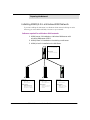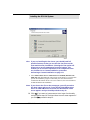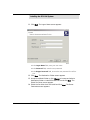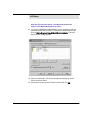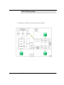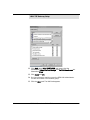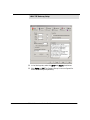
1
SERVER INSTALLATION GUIDE
NOTICE
The information contained in this document is believed to be accurate in
all respects but is not warranted by Mitel Networks Corporation (MITEL®).
The information is subject to change without notice and should not be
construed in any way as a commitment by Mitel or any of its affiliates or
subsidiaries. Mitel and its affiliates and subsidiaries assume no
responsibility for any errors or omissions in this document. Revisions of
this document or new editions of it may be issued to incorporate such
changes.
No part of this document can be reproduced or transmitted in any form or
by any means - electronic or mechanical - for any purpose without written
permission from Mitel Networks Corporation.
COPYRIGHT
6510 Unified Messaging Server Installation Guide
50003291, Rev. A
Release 1.1
January 2003 (Draft)
®,™ Trademark of MITEL Networks Corporation
©Copyright 2003, MITEL Networks Corporation
All rights reserved
TRADEMARKS
MITEL and Mitel Networks are trademarks of
Mitel Networks Corporation.
MS-DOS is a registered trademark of Microsoft Corporation.
Brooktrout is a registered trademark of Brooktrout, Inc.
Dialogic and Gammalink are registered trademarks of
Dialogic Corporation.
Other brands and their products are trademarks or registered
trademarks of their respective holders and should be noted as such.
Table of Contents
About This Guide 7
Document Overview 8
Intended Audience 8
Before You Begin 8
Conventions 8
Contacting Mitel Networks™ 9
CHAPTER 1
Preparing the Network
11
Overview 12
Hardware Requirements 12
Software Requirements 16
MSMQ Overview 17
MSMQ Installation Overview 18
Overview of the Installation Procedure for MSMQ Server 1.0 20
Installing SQL 7.0 for MSMQ 1.0 server 21
Installing the MSMQ Server 1.0 Overview 24
Installing MSMQ Server (PEC) 1.0 26
Installing MSMQ 1.0 Client on Windows NT 4.0 29
Installing MSMQ 2.0 Client on Windows 2000 Professional for
MSMQ server 1.0 31
Using the MSMQ Explorer 33
Installing MSMQ 2.0 in a Windows 2000 Network 34
Installing MSMQ 2.0 Server 35
Installing MSMQ 2.0 Client 38
Installing Microsoft IIS5 42
Installing the Loopback Driver on a Standalone System 44
CHAPTER 2
Installing the 6510 UM System
47
Overview 48
6510 UM Installation 50
Installing RealSpeak TTS 3.00 56
Installing the Dialogic Voice Board Driver 59
6510 UM Server Installation Guide
3
Table of Contents
Installing the Brooktrout Voice Board Driver 73
Installing the MSS Server 76
Installing the RIM MSS Connector 80
Installing the MSS Connector for Exchange 5.5 82
Installing MSS Connector for Exchange 2000 86
Installing MSS Connector for Lotus Notes 90
Installing the Voice Processing Server 93
Configuring DCOM 98
Configuring DCOM for the 6510 UM 98
Installing Fax Services 116
Performing a Custom Installation 121
Installing the Brooktrout Fax Driver 124
Installing the Gammalink Fax Driver 125
Installing Additional Languages 128
Uninstalling the Voice Processing Server 133
CHAPTER 3
Installing 6510 UM with the UM TSE
IMAP Gateway 137
Installing 6510 UM with the UM TSE IMAP Gateway 138
6510 UM Installation 139
Installing RealSpeak TTS 3.00 144
Installing the Dialogic Voice Board Driver 148
Installing the Brooktrout Voice Board Driver 162
Installing the Voice Processing Server 165
Configuring DCOM 170
Configuring DCOM for the 6510 UM 171
Installing Fax Services 188
Performing a Custom Installation 193
Installing the Brooktrout Fax Driver 196
Installing the Gammalink Fax Driver 197
4
6510 UM Server Installation Guide
Table of Contents
CHAPTER 4
MSS Setup
199
MSS Setup 200
Understanding MSS 200
Using a Centralized Queue Server 200
Enabling the MSS Voice Mail Connector 209
Managing the Synchronization Schema 212
Maintaining the Client’s Property Page 217
Maintaining the Databases Property Page 224
Installing MSS Connector Client-Side Extension 234
Configuring the MSS Connector for Lotus Client Extension 235
Configuring Lotus Notes Minder 237
Lotus Domino Settings Configuration 238
Understanding the RIMMSS Connector 251
Configuring the RIMMSS Connector 251
Configuring the RIMMSS Software 254
Registering a User with Exchange 2000 256
Registering an Existing Exchange User 263
Binding a Wireless User with UM and Messaging Server 266
Installing MSS Connector on the Blackberry Device 267
Uninstalling the MSS Server and Connector 267
CHAPTER 5
IMAP TSE Gateway Setup
273
Overview 274
Operation Requirements 276
Data Flow 276
Integrating the IMAP TSE Gateway 277
Configuring IMAP TSE Gateway for Lotus Domino Server 311
LDAP Import Utility 319
Configuring IPSec 334
6510 UM Server Installation Guide
5
Table of Contents
Fax Services Setup
CHAPTER 6
343
Fax Setup 344
Installing the Gammalink Fax Card 344
Starting the GammaLink Service 346
Configuring the Fax Settings 347
Using Fax On Demand 351
Installing and Configuring Fax On Demand 351
Configuring the Voice Mail System Environment 352
Using Fax Mail 357
Accessing or Configuring Fax Messaging 357
Gammalink Fax Board 360
Installing Optional Modules
CHAPTER 7
365
Overview 366
Installing Local Area Paging (LAP) 366
Completing the Licensing Agreement 366
Installing the Paging Transmitter System 367
Configuring Local Area Paging 368
Configuring LAP for each Mailbox 369
Installing an Additional Language 376
Installing an Optional Language 376
Folder Structure and File Description
CHAPTER 8
Storing 6510 UM Files 384
Handling the Application Folder 384
Sentinel (For license use) 385
Handling the Windows Folder 386
Index 389
6
6510 UM Server Installation Guide
383
About This Guide
In This Chapter...
Document Overview on page 8
Intended Audience on page 8
Before You Begin on page 8
Conventions on page 8
Contacting Mitel Networks on page 9
6510 UM Server Installation Guide
7
About This Guide
Document Overview
This guide provides detailed instructions on installing the 6510 Unified Messaging
(UM) software.
Note: The information in this document is draft content only. As well, some screen
captures may not reflect the Mitel Networks™ 6510 UM software exactly. All
content and screens will be updated in the next release of this document.
Intended Audience
This guide is intended for anyone responsible for installing and maintaining the
6510 Unified Messaging software, including IT Administrators.
Before You Begin
Before you begin, ensure that you have fulfilled both the hardware and software
requirements.
Conventions
This guide contains three types of help:
Note: Contains additional information about the task you are performing
Hint: Contains an alternative method of performing the task or offers a
solution if you run into a problem.
Caution: Information that alerts you to potential loss of data or
potential damage to an application, system, or device.
Warning:Information that alerts you to potential personal injury.
8
6510 UM Server Installation Guide
About This Guide
Contacting Mitel Networks
Contact us by mail at:
Mitel Networks Corporation
350 Legget Drive
Ottawa, ON K2K 2W7
Contact us by phone:
Tel: 613-592-2122
Fax: 613-592-4784
Contact us on the Web:
www.mitel.com
6510 UM Server Installation Guide
9
About This Guide
10
6510 UM Server Installation Guide
CHAPTER 1
Preparing the Network
In This Chapter . . .
Overview on page 12
Hardware Requirements on page 12
Software Requirements on page 16
MSMQ Overview on page 17
MSMQ Installation Overview on page 18
Installing MSMQ 2.0 in a Windows 2000 Network on page 34
Installing Microsoft IIS5 on page 42
Installing the Loopback Driver on a Standalone System on page 44
6510 UM Server Installation Guide
Preparing the Network
Overview
To start the 6510 UM server installation, you must connect the 6510 UM server to
your network via the 100 baseT NIC interface on the back of the server and then
boot up the server.
Before installing the 6510 UM system, you must install the following software:
1. MSMQ
2. Microsoft IIS
3. The latest Service packs for Windows 2000 or Windows NT 4.0,
minimum SP2
4. The latest Windows update (after installing IIS and MSMQ)
5. The Loopback Driver (on standalone systems)
In addition, you must also connect the 6510 UM server to your network via the 100
baseT NIC interface on the back of the server, then boot up the server.
Note: Make sure that you provide the UM server with the proper
administrative rights to the network so it can co-exist as
another workstation on your LAN. For more information,
contact your LAN Administrator.
Hardware Requirements
6510 UM runs on a wide variety of configurations. The following tables illustrate
the hardware required to run the software, based on port configuration.
Note: The following tables depict recommended hardware
requirements. To ensure the proper functioning of your 6510
UM system, contact Mitel Networks for your exact hardware
requirements.
12
6510 UM Server Installation Guide
Preparing the Network
Warning: Do not connect the Dialogic D/42 or D/82 digital interfaces (SELV),
or the Gammalink CPI200 or CPI400 ONS interfaces (TNV-1)
directly to the Public Switched Telephone Network (PSTN). Connect these interfaces only to a fully approved private branch
exchange (PBX) switch. Any connection of these interfaces to an
off premise application, an out of plant application, any other
exposed plant application, or to any equipment other than the
intended application may result in a safety hazard, and/or defective operation, and/or equipment damage. "Exposed plant"
means an area where any portion of the circuit is subject to accidental contact with electric lighting, an area with power conductors operating at a voltage exceeding 300 V between conductors,
or an area that is subject to lightning strikes.
1 to 16 Port Configuration
The following table illustrates the hardware and software components
recommended to run 6510 UM on a 1 to 16 port configuration with 2 ASR ports,1
ASR language, 2 TTS ports and 1 TTS language.
Hardware
Component Specifications
CPU
Intel Pentium 4 ( Socket 478) 1.7Ghz Retail
Package/W Genuine Intel Fan
RAM
768MB RD RAM
Hard Drive
30 GB IDE
CDROM
Required
VGA
32MB 4X AGP TNT 2 Pro
NIC
1X100 BaseT.
Modem
56K v.90 min (remote maintenance)
OS
Windows 2000 Professional
6510 UM Server Installation Guide
13
Preparing the Network
16 to 24 Port Configuration
The following table illustrates the hardware and software components
recommended to run 6510 UM on a 16 to 24 port configuration with 2 ASR ports,
1 ASR language, 2 TTS ports and 1 TTS language.
14
Hardware
Component Specifications
CPU
Intel Pentium 4 ( Socket 478) 1.7Ghz Retail
Package/W Genuine Intel Fan
RAM
768MB RD Ram
Hard Drive
30 GB SCSI A
CDROM
Required
VGA
32MB 4X AGP TNT 2 Pro
NIC
1X100 BaseT.
Modem
56K v.90 min
OS
Windows 2000 Server
6510 UM Server Installation Guide
Preparing the Network
26 to 32 Port Configuration
The following table illustrates the hardware and software components
recommended to run 6510 UM on a 26 to 32 port configuration with 2 ASR ports,
1 ASR language, 2 TTS ports and 1 TTS language.
Hardware
Component Specifications
CPU
Intel Pentium 4 ( Socket 478) 2Ghz Retail
Package/W Genuine Intel Fan
RAM
Hard Drive
768MB RDRam
RAID 5 SCSI setup. 4 drives each at 18GB =
approx 54 GB of storage and fast R/W.
CD-ROM
Required
VGA
32MB 4X AGP TNT 2 Pro
NIC
1X100 BaseT
Modem
56K v.90 min
OS
Windows 2000 Server
6510 UM Server Installation Guide
15
Preparing the Network
Software Requirements
The following table illustrates the minimum software required to run 6510 UM.
Microsoft Software
Specifications
OS
Windows 2000 Professional/Server Service
Pack 2 (SP2).
Note: Run service pack install after
completing UM server installation
16
MSMQ for an NT 4
network
MSMQ V. 1.0 bundled with Option pack 2 CD
for NT 4 OS. SQL Server 7.0 or higher
MSMQ for a Windows
2000 network
MSMQ 2.0 server or higher
Microsoft exchange 5.5
Service pack 3 or higher
Microsoft Exchange 2000
Service pack 2 or higher
3rd Party Software
Specifications
TTS Software
RealSpeak
Remote maintenance
PC anywhere - Version 10
6510 UM Server Installation Guide
Preparing the Network
MSMQ Overview
MSMQ software uses a centralized queue server (Primary Enterprise Controller or
PEC) and a set of MSMQ clients. There are two types of clients— dependent and
independent—but only independent clients might be used with MSS.
A Primary Site Controller (PSC) and a Backup Site Controller (PDC) control single
sites. The 6510 UM system uses the Primary Enterprise Controller (PEC), which is the
global catalogue for the entire MSMQ schema. Within the enterprise, there can be
multiple sites that are not used. The 6510 UM system does not support (from MSS)
cross domain, or different subnet configurations, therefore, the PEC can be
considered to be acting as a PSC since it technically only controls one site.
MSS software runs under both Windows NT 4.0 and Windows 2000 platforms.
Due to using MSMQ, you must install and configure TCP/IP services on each
machine that runs MSS software. All machines should be configured to use
DNS name resolution.
Many distributed applications need the ability to handle delays between a request
and a response. This is because all the steps of a distributed application process may
not need to or cannot be completed at one time. Microsoft Message Queuing
(MMQ) allows applications to use components that communicate with one another
using queued messages. Like e-mail messages that sit in an inbox, messages can
exist on dissimilar systems that may not even be directly communicating with each
other.
6510 UM Server Installation Guide
17
Preparing the Network
MSMQ Installation Overview
The following steps are required to install MSMQ:
1. For an NT 4.0 network, install MSMQ 1.x on a network domain
controller (Windows NT4). For more information, proceed to
Overview of the Installation Procedure for MSMQ Server 1.0 on
page 20.
2. For a Windows 2000 network, install MSMQ 2.0 server on a
network domain controller (Windows 2000). For more
information, proceed to Installing MSMQ 2.0 in a Windows 2000
Network on page 34.
3. Install MSMQ as an independent client on your e-mail server. For
more information, proceed to Installing MSMQ 2.0 Client on
page 38.
4. Connect the VM Server to the domain, then install MSMQ on the
6510 UM system. For more information, proceed to Testing for
MSMQ Connectivity on page 40.
Typically, the MSS server and MSMQ primary enterprise controller executed (PEC),
should be on the same computer, that belongs to some Windows NT domain or
acts as a PDC or BDC for domain.
Messaging servers and MSS connectors can be executed on computers that belong
to same domain as computer that runs MSS server. Each machine that has MSS
connector installed should run MSMQ independent client connected to MSMQ
primary enterprise controller (see explanation below).
Make sure that computers that are supposed to run MSS server or MSS connectors
have Windows NT Server 4.0 / Windows 2000 Server or NT 4.0 workstation/ 2000
professional is installed and configured. Each computer should belong the same
Windows domain.
Caution: You will need Administrator rights for the domain in order to
install MSMQ and the MSS software. The IP of the UM Server
must be static.
18
6510 UM Server Installation Guide
Preparing the Network
NT 4.0 Network Requirements for MSMQ
There are four components required to run MSMQ on an NT 4.0 Network:
1. SQL 7.0
2. MSMQ Server
3. MSMQ 1.0 Client on Windows NT 4.0
4. MSMQ 2.0 Client on Windows 2000
MSMQ 1.0 Server Requirements
The following servers are used by MSMQ:
1. PEC - Primary Enterprise Controller (PEC) is another term for the
MSMQ server
2. PDC - Primary Domain Controller, used for user authentication
3. BDC - Backup Domain Controller, used to assist user authentication
4. MSMQ routing servers
Connectivity Requirements
1. The following requirements must be met for correct connectivity:
2. Each MSMQ controller server must meet the connectivity
requirements of the enterprise.
3. PDCs (and the PEC) must share a CN with every other PSC.
4. BDCs must share a CN with the PDCs or the PEC they back up.
5. Every MSMQ independent client and MSMQ routing server must
share a CN with at least one PDC/PEC or BDC within its own site.
Ensuring Optimal Performance
To ensure optimal performance, do not install MSMQ servers on a primary domain
controller (PDC) or a backup domain controller (BDC) . PDCs and BDCs maintain
and replicate the network accounts database and perform network login
authentications, which are resource-intensive tasks.
If you have a very small network in which account information rarely changes, and
6510 UM Server Installation Guide
19
Preparing the Network
in which users do not log on and off frequently, you can use the same server as both
a domain controller and an MSMQ server.
Note: MSMQ controller servers PEC, PDCs, and BDCs) use a SQL
Server version 7.0 database to store the MQIS.
Specifying MSMQ Controller Server Computer Names
To ensure that SQL installs correctly, the MSMQ controller server’s computer name
must be a valid SQL identifier, with the first character of the computer name being a
letter or an underscore. Characters following the first character can include letters,
numbers, or the symbols -, #, $, or _. However, no embedded spaces are allowed.
If your computer name contains a hyphen, the SQL Server Setup will display a
warning message stating that the computer name is not valid. If characters that SQL
does not recognize are used in the computer name, you must rename the computer
before installing MSMQ or SQL Server. For instructions on renaming computers,
refer to the Windows NT online Help.
If the renamed computer is a member of a Windows NT Server domain, contact
your network administrator to have the new computer name added to the domain.
Overview of the Installation Procedure for MSMQ Server 1.0
Perform the following steps to install MSMQ Server 1.0:
1. Install NT 4.0 server use standard install.
2. Apply service pack 3.0.
3. Install service pack 5.0 or higher.
4. Install Microsoft IE 5.5 or higher.
5. Install SQL 7.0. Make sure the following registry key exists before
proceeding:
HKEY_LOCAL_MACHINE\SOFTWARE\Microsoft\MSSQLServer\Setup"SQLPath"="C:\MSSQL"
6. From the NT4.0 option pack disk, install MSMQ as a PEC.
7. Use Explore to ping MSMQ to verify it is working.
8. Apply NT 4.0 service pack 4.0 or higher.
20
6510 UM Server Installation Guide
Preparing the Network
Installing SQL 7.0 for MSMQ 1.0 server
You must have both Service Pack 5 and IE 4 to install SQL 7.0. You will install SQL on
the same machine that you plan to install the MSMQ1.0 server software on. MSMQ
users the SQL database to store event queues in the network.
To install SQL 7.0:
1. Insert the Windows NT 4.0 Option Pack CD into the CD-ROM drive.
The Welcome screen appears.
2. Double-click Select SQL Server 7.0 Components. The Install SQL
Server 7.0 Components dialog appears.
6510 UM Server Installation Guide
21
Preparing the Network
3. Double-click Database Server - Desktop Edition. The Select Install
Method dialog appears.
4. Select Local install – Install to the Local Machine, then click Next.
The Welcome dialog appears.
5. Click Next. The Software License Agreement dialog appears.
6. Click Yes. The User Information dialog appears.
7. In the Name field, enter the user’s name
8. In the Company field, enter the company name and click Next. The
Setup Type screen appears.
22
6510 UM Server Installation Guide
Preparing the Network
9. Click on Typical Installation, leaving the destination folders as their
default settings and click Next. The Services Accounts dialog
appears.
10. Select Use the same account for each service. Auto start SQL Server
Service.
11. In the Service Settings, select Use the Local System account as the
service setting and click Next. The Start Copying Files dialog
appears.
12. Click Next. The Setup process begins. After the Setup process
completes, the Setup Complete dialog appears. Click Finish, then
restart the computer.
Once the SQL server installation is complete you can now proceed to install MSMQ
server 1.0.
6510 UM Server Installation Guide
23
Preparing the Network
Installing the MSMQ Server 1.0 Overview
The Microsoft Message Queue (MSMQ) server is installed as part of the Windows
NT 4.0 Option Pack installation. When the MSMQ is selected, it inserts
configuration dialog boxes both before and after the Option Pack file copying
process. If you elected to install the Microsoft Message Queue server, the MSMQ
Setup dialog box appears and prompts you to choose the MSMQ server or client
component to install. By default, the Primary Enterprise Controller (PEC) option is
selected, with the PEC containing the master copy of the MSMQ Information Store.
Note: For an enterprise network, a Primary Enterprise Controller is
required in order for other MSMQ servers or clients to be
installed.
Note: For MSMQ Server 1.0 installation, the system refers to the
PDC and BDC as the PSC and BSC respectively. See
Overview on page 12 for more details.
In addition to the Primary Enterprise Controller option, the Message Queue server
dialog box enables you to select six other options, specifically:
24
Option
Function
Primary Site Controller (PSC)
A primary site controller is required at each
site.
Backup Site Controller (BSC)
Backup site controllers are not required, but
are recommended for failure recovery.
Routing Server
A routing server provides routing, store and
forward services, and remote message store
Independent Client
Independent clients contain their own
message stores, and can send or receive
messages
6510 UM Server Installation Guide
Preparing the Network
Dependent Client
Dependent clients require an active network
connection and do not contain their own
message stores.
RAS Connectivity Service
The RAS connectivity service enables remote
clients to use MSMQ message services.
Note: If this is the first MSMQ installation on the network, you
must select the Primary Enterprise Controller option.
Otherwise, choose the type of MSMQ installation you want to
perform.
6510 UM Server Installation Guide
25
Preparing the Network
Installing MSMQ Server (PEC) 1.0
The Primary Enterprise Controller (PEC) is another term for the MSMQ server. A
complete MSMQ install is called an Enterprise, and the assigned server is the main
controller or PEC.
Note: Before you start, make sure that Windows NT Server 4.0 is
installed and configured.
To install MSMQ Server:
1. Insert the Windows NT 4.0 Option Pack CD into the CD-ROM drive.
In a few seconds, the Welcome dialog appears.
2. Click Next. The End User License Agreement dialog appears.
3. Click Accept, then Next. The following dialog appears.
4. Click Custom. The Select Components dialog appears.
26
6510 UM Server Installation Guide
Preparing the Network
5. Click Next. The Server Type dialog appears.
6. Select Primary Enterprise Controller (PEC) and click Continue. The
Information Server Database on SQL Server dialog appears.
7. Use the default options for MSMQ database and click Continue.
The New Enterprise dialog appears.
8. In the Enterprise Name field, enter the Enterprise name for MSMQ
Enterprise and click Continue. The New Connected Network dialog
appears.
9. In the Connected Network Name field, enter the name of the
Domain. Select IP as the Protocol and click OK. The Connected
Networks dialog appears.
6510 UM Server Installation Guide
27
Preparing the Network
10. Click Add. The New Site dialog appears.
11. In the Site Name field, enter the name of the site, then click
Continue. The MSMQ Server setup is now complete.
12. Install MSMQ clients on all computers those supposed to run MSS
software and configure MSMQ software.
13. Use MSMQ Explorer to make sure that new MSMQ Enterprise was
created.
28
6510 UM Server Installation Guide
Preparing the Network
Installing MSMQ 1.0 Client on Windows NT 4.0
Before you start, identify the operating system that the client is running. MSMQ1.0
client can be installed on Windows NT 4.0
To install MSMQ 1.0 Client on Windows NT 4.0:
1. Insert the Windows NT 4.0 Option Pack CD into the CD-ROM drive.
In a few seconds, the Welcome dialog appears.
2. Click Next. The End User License Agreement dialog appears.
3. Click Accept, then Next. The following Option Pack dialog
appears.
4. Click Custom. The Select Components dialog appears.
5. Check Microsoft Message Queue, then click Next. The Information
Server Setup dialog appears.
6510 UM Server Installation Guide
29
Preparing the Network
6. In the MTS Install Folder field, enter the installation folder for
Microsoft Transaction Server, then click Next. The following dialog
appears.
7. Select Local as the administration mode for Microsoft Transaction
Server, then click Next. The following dialog appears.
30
6510 UM Server Installation Guide
Preparing the Network
8. Select Independent Client as the type of MSMQ software that you
want to install, then click Next.
9. Click Next. The Microsoft Message Queue Setup dialog appears.
10. Specify the name of the computer running MSMQ Server. If MSMQ
1.0 server is used, specify the name of primary enterprise
controller.
11. Click Next. The Microsoft Message Queue Setup dialog appears.
12. Specify installation folder for MSMQ software, then click Next.
13. Click Finish. The a confirmation message appears.
14. Click Yes. After the system has restarted, use MSMQ Explorer to
make sure that the new MSMQ client was created.
Installing MSMQ 2.0 Client on Windows 2000 Professional
for MSMQ server 1.0
Before you install MSMQ 2.0 Client on Windows 2000 professional integrated with
a MSMQ1.0 server, make sure that you have:
1. Installed and configured Windows 2000
2. Installed MSMQ 1.0 Server software on the primary site controller.
3. Made sure that the computer is part of the Windows NT 4.0
Domain where the MSMQ 1.0 Server is installed.
To install MSMQ 2.0 Client:
1. Click Start > Settings > Control Panel. The Control Panel window
appears.
2. Double-click Add/Remove Programs. The Add/Remove Programs
window appears.
6510 UM Server Installation Guide
31
Preparing the Network
3. Click Add/Remove Windows Components. The Windows
Components dialog appears.
4. Select Message Queuing Services, then click Next. The Message
Queuing Type dialog appears.
5. Select Independent Client, then click Next. The Configuring
Components dialog appears, the software will search for the PEC
connected to the Network, and begins installing MSMQ.
Note: If the Windows version is 2000 Server, the Independent Client
option is displayed as Message Queuing Server.
Hint: If the Dependent Client is grayed out and not available for
selection, then you must re-check your network configuration
before proceeding.
6. Click Finish, do not proceed with the terminal server installation
when installation is complete. Restart the computer. After the
system has restarted, use MSMQ Explorer to make sure that the
new MSMQ client was created.
32
6510 UM Server Installation Guide
Preparing the Network
Using the MSMQ Explorer
The MSMQ Explorer is a Windows-based management tool for administering
MSMQ operations on your network. This test is a mandatory requirement before
starting MSS installation.
To use MSMQ Explorer:
1. To run MSMQ Explorer, click Start > Programs > Windows NT 4.0
Option > Pack Microsoft Message > Queue Explorer. The Tools
menu provides the following options:
Options
Function
Find
Find a Computer or Queue
Purge Queue
Purge the contents of a queue
Send Test Message
Test a message queue
Remove User Certificates
Remove the certificate from a selected user
account.
You must be able to find other machines that have MSMQ installed. If you cannot
find a MSMQ client to the MSMQ server (or vice versa), do not install the MSS
middleware service for Unified messaging.
6510 UM Server Installation Guide
33
Preparing the Network
Installing MSMQ 2.0 in a Windows 2000 Network
If you are installing the UM server in a Windows 2000 network utilizing an active
directory, you must add the MSMQ 2.0 server to your network.
Software required for a Windows 2000 network:
1. MSMQ server 2.0 installed on a Windows 2000 server with
windows 2000 server OS SP2
2. MSMQ Client 2.0 installed on the existing e-mail server
3. MSMQ client 2.0 installed on the UM Server
Computer roles:
NT: DC for domain TEST1
Software installed:
Windows 2000 Server sp2
PDC
Email
34
DC
UC
Computer roles:
NT: DC in domain TEST1
MSMQ 2.0 PEC
MSS: MSS Connector
Computer roles:
NT: DC in domain TEST1
MSMQ 1.0 Client
MSS: MSS Administration
Computer roles:
NT: Work Station
Software installed:
Windows 2000 Server sp2
Exchange Server 2000 sp2
Message Queue Server 2.0,
MSS Connector for Exchange
Software installed:
Windows NT 4.0 Server SP6
Software installed:
Windows 2000 Pro SP2,
3Com UC
Message Queue 2.0 Client
MSS Connector for UC
Message Queue Client 1.0
MSS Server
6510 UM Server Installation Guide
MSS: MSS Connector
Preparing the Network
Installing MSMQ 2.0 Server
Before you install MSMQ 2.0, make sure that:
1. You have installed and configured the active directory services.
2. You have reinstalled the latest Windows service pack following the
MSMQ and IIS installation and setup
To install the MSMQ 2.0 Server:
1. Click Start > Settings > Control Panel on the machine that you plan
to install the MSMQ server on. The Control Panel window appears.
2. Double-click Add/Remove Programs. The Add/Remove Programs
window appears.
3. Click Add/Remove Windows Components, select Message Queuing
Services and click Next. The Terminal Services Setup dialog
appears.
4. Select Remote Admin for remote administration or Application
Admin for application administration. The Windows Components
dialog appears.
5. Click Next. The Message Queuing Type dialog appears.
6. Select Message Queuing server, then click Next.
6510 UM Server Installation Guide
35
Preparing the Network
7. The Windows 2000 Messaging Queuing Clients dialog appears.
8. Click Next. The Setup program begins to configure the
components. After the installation is complete verify MSMQ is
installed properly through active directory.
Verifying the Installation of MSMQ on Windows 2000
Follow this procedure to view the MSMQ server in the network.
To verify the server software:
1. Open Active directory sites and services snap-in.
2. Make sure that the server where you have installed MSMQ server
is the global catalog for active directory by viewing the properties
for NTDS services for this server.
36
6510 UM Server Installation Guide
Preparing the Network
3. Open Active directory Users and Computers snap-in.
4. Select View>Advanced features.
5. Select View>Users and computers as containers.
6. Make sure that MSMQ object appears under computer where you
have installed MSMQ services.
7. Restart your PC.
6510 UM Server Installation Guide
37
Preparing the Network
Installing MSMQ 2.0 Client
Before you start, make sure that you have:
1. Installed and configured Windows 2000.
2. Made sure that the computer is part of either the Windows NT 4.0
Domain (where the MSMQ 1.0 Server is installed), or the Windows
2000 Domain running ADS (Active Directory Service).
3. Installed MSMQ server software on a Windows 2000 domain
controller.
4. MSMQ 2.0 server software installed on the designated server
machine.
5. Installed and configured Windows 2000, and that the active
directory services are installed and configured.
6. Installed the latest Windows service packs and updates following
installation.
To install MSMQ 2.0 Client
1. Click Start > Settings > Control Panel. The Control Panel window
appears.
2. Double-click Add/Remove Programs. The Add/Remove Programs
window appears.
38
6510 UM Server Installation Guide
Preparing the Network
3. Click Add/Remove Windows Components. The Windows
Components dialog appears.
4. Select Message Queuing Services, then click Next. The Message
Queuing Type dialog appears.
5. Select Independent Client, then click Next. The Configuring
Components dialog appears and begins installing MSMQ.
Note: If the Windows version is 2000 Server, the Independent Client
option is displayed as Message Queuing Server.
Note: The software will search for the PEC connected to the
network. If the PEC is installed with NT4 OS, you have to
manually identify the MSMQ Server
6. Click Finish when the installation process is finished.
6510 UM Server Installation Guide
39
Preparing the Network
Verifying MSMQ Client on Windows 2000
After you install MSMQ, you must make sure that you can view the MSMQ server
on Windows 2000.
To verify MSMQ Client on Windows 2000:
1. If MSMQ server software installed on Windows 2000, then Open
Active directory sites and services snap-in.
2. Make sure that the server where MSMQ server installed is the
global catalog for active directory by viewing properties for NTDS
services for this server. Open Active directory users and computers
snap-in.
3. Select View > Advanced.
4. Select View > Users and Computers as containers.
5. Make sure that MSMQ object appears under computer where you
have installed MSMQ services.
Testing for MSMQ Connectivity
Before you install MSS, check that your network environment can accommodate
the software requirements.
Install MSMQ client on the mail server. From MSMQ Explorer (NT 4.0) or active
directory (Windows 2000), you must able to view client MSMQ computers. If you
can ping the e-mail server from the Domain controller with MSMQ server, then the
site is ready for a UM deployment.
40
6510 UM Server Installation Guide
Preparing the Network
To test for MSS Compliance in a Windows 2000 Environment:
1. Ensure the view is set accurately in active directory.
2. Make sure that MSMQ is added to the computer object for e-mail
& voice server as above.
3. Right click on MSMQ object under each computer and select
properties.
4. Click on the MQPing button to ensure you can receive a reply from
the MSMQ server. Repeat the process for each computer with
MSMQ.
6510 UM Server Installation Guide
41
Preparing the Network
Installing Microsoft IIS5
The following procedure installs Microsoft IIS5 on the 6510 UM Server.
To install Microsoft IIS5:
1. Insert the Windows 2000 installation CD into the CD-ROM drive.
The Install Add-On Components dialog appears.
2. Select Install Add-On Components. The Windows Components
Wizard dialog appears.
3. Select Internet Information Services (IIS), then click Details to make
sure that all components have been selected. The Internet
Information Services (IIS) dialog appears.
Note: You do not have to select the RAD option.
4. Click OK. The Configuring Components dialog appears.
5. Click Next to begin the installation. The system begins installing
IIS.
6. Click Finish when installation is complete.
7. After you have installed all of the software, run the Windows
Update program and make sure that you re-install Service Pack 2
for Windows 2000.
42
6510 UM Server Installation Guide
Preparing the Network
8. Reboot the system.
9. After rebooting, check to see if you can browse the queues. Create
a test queue, then use MSQ’s Ping utility to test the installation.
10. Make sure that MSMQ is added to the computer object for e-mail
& voice server as above.
11. Right-click on MSMQ object under each computer and select
properties.
12. Click on the MQPing button to ensure you can receive a reply from
the MSMQ server. Repeat the process for each computer with
MSMQ.
6510 UM Server Installation Guide
43
Preparing the Network
Installing the Loopback Driver on a Standalone System
The client and server communications mechanism for speech services is based on
Winsockets that are available on any client and host machine that is connected to a
network. However, if the target platform is a standalone machine that is not
connected to a network, a loopback driver must be installed.
Note: Before installing the loopback driver, ensure that TCP/IP is
installed on the standalone machine.
To install the loopback driver:
1. In the Windows taskbar, click Start>Settings>Control Panel. The
Control Panel window appears.
2. Double-click Add/Remove Hardware. The Add/Remove Hardware
Wizard Welcome dialog appears.
3. Click Next. The Choose a Hardware Task dialog appears.
44
6510 UM Server Installation Guide
Preparing the Network
4. If there are any network adapter cards currently installed on the
machine, select Uninstall/Unplug a device and click Next. The
Choose a Removal Task dialog appears. If there are no network
adapter cards currently installed, proceed to step 7.
5. Select Uninstall a device and click Next. The Installed Devices on
Your Computer dialog appears.
6. Select the network adapter cards that are installed and click Next
to uninstall these components. After uninstalling, return to the
Choose a Hardware Task dialog.
7. Select Add/Troubleshoot a device. The New Hardware Detection
dialog appears, and the system compiles a device list that displays
in the Choose a Hardware Device dialog.
8. Select Add a new device and click Next. The Find New Hardware
dialog appears.
9. Select No, I want to select the hardware from a list and click Next.
The Hardware Type dialog appears.
10. Select Network Adapters and click Next. The Select Network
Adapter dialog appears.
6510 UM Server Installation Guide
45
Preparing the Network
11. Under Manufacturers, select Microsoft and under Network
Adapter, select Microsoft Loopback Adapter and then click Next.
The Start Hardware Installation dialog appears.
12. Click Next. The system begins to install the loopback adapter.
When finished, the Completing the Add/Remove Hardware Wizard
dialog appears.
13. Click Finish to complete the installation.
46
6510 UM Server Installation Guide
CHAPTER 2
Installing the 6510 UM System
In This Chapter...
6510 UM Installation on page 50
Installing RealSpeak TTS 3.00 on page 56
Installing the Dialogic Voice Board Driver on page 59
Installing the Brooktrout Voice Board Driver on page 73
Installing the MSS Server on page 76
Installing Connectors page 80
Installing the Voice Processing Server on page 93
Configuring DCOM on page 98
Installing Fax Services on page 116
Installing the Brooktrout Fax Driver on page 124
Installing the Gammalink Fax Driver on page 125
Installing Additional Languages on page 128
6510 UM Server Installation Guide
Installing the 6510 UM System
Overview
This installation guide outlines the installation procedures for the 6510 Unified
Messaging system with MSS and the 6510 Unified Messaging system with the UM
TSE IMAP Gateway.
• For instructions on installing 6510 UM with MSS, proceed to Before
You Begin on page 49.
• For instructions on installing 6510 UM with IMAP, proceed to
Chapter 3.
To fully install the 6510 Unified Messaging system with MSS, the following
components must be installed:
1. Voice Mail Software
• Text to Speech Services (RealSpeak TTS)
• Languages
• Voice Driver (Brooktrout or Gammalink)
• Voice Processing Server
• DCOM Configuration
2. MSS Services
• MSS Server
• MSS Connector
• MSS Exchange 5.5 Connector
• MSS Exchange 2000 Connector
• Lotus Notes Connector
• MSS Connector Client-Side Extension
• RIMMSS Connector for Blackberry Wireless Devices
• MSS Connector for the Blackberry Device
48
6510 UM Server Installation Guide
Installing the 6510 UM System
3. Fax Services
• 6510 UM Fax Server
• Fax Board Driver (Gammalink or Brooktrout)
Before You Begin
If you are planning to install the MSS Connector for Lotus Notes, make sure that
you have completed the steps below. The complete Lotus Notes Connector
installation consists of two steps:
1. Installing the Lotus Notes Connector
2. Installing the MSS Connector Client-Side Extension.
Warning: If you plan to integrate your unified messaging system with
Lotus Notes, you must configure all feature groups to use.WAV
format and a Dialogic JTC voice board must be used. For more
information, refer to the Feature Group chapter in the Server
Configuration Guide.
Before installing the MSS connector for DominoR.5, make sure that you have:
• Installed Windows NT 4.0 SP6 or Windows 2000 SP2.
• Verified that connectivity between the Domino server computer and
the MSS server computer is configured.
• Verified that MSMQ nodes (server or client) on the MSS server computer and Domino server computer can communicate by using
MQPing.
• Verified that your Domino server version is 5.0.9 or higher.
• Verified that your MSS server is installed and configured.
6510 UM Server Installation Guide
49
Installing the 6510 UM System
6510 UM Installation
The 6510 UM Installation procedure uses a simple and convenient interface that
allows you to select the components that you want to install. Upon selecting the
components in the Installation Main Menu, the Installation Wise Wizard
automatically installs each selected component, guiding you through each step of
the installation process.
To install 6510 UM:
1. Insert the Installation CD 1 into the CD-ROM drive. The Welcome
screen appears.
2. Click Next. The 6510 UM Server Installation Main Menu window
appears.
50
6510 UM Server Installation Guide
Installing the 6510 UM System
3. Declare the components that you want to install by selecting the
corresponding checkboxes. To install 6510 UM with MSS, the
Unified Messaging Services checkbox must be selected.
Note: For this installation guide, the full installation of all
components is illustrated.
Hint: Click the Documents button to obtain a copy of this guide or
any other 6510 UM related document in .pdf format.
4. Click Next. The RealSpeak Languages dialog appears.
6510 UM Server Installation Guide
51
Installing the 6510 UM System
5. Select the languages that you want to install and click Next. The
Voice Drivers dialog appears.
52
6510 UM Server Installation Guide
Installing the 6510 UM System
6. Select the Voice Driver that you want to install and click Next. The
Unified Messaging Services dialog appears.
6510 UM Server Installation Guide
53
Installing the 6510 UM System
7. Select the checkbox that corresponds to the Unified Messaging
components that you want to install and click Next. The Fax
Drivers dialog appears.
Note: Only one connector can be installed per machine. To install
another Connector, you must repeat this process on a
different machine.
54
6510 UM Server Installation Guide
Installing the 6510 UM System
8. Select the checkbox that corresponds to the fax driver that you
want to install. (The fax driver selected must match the voice
board that is installed on your system).
9. Click Next. The Installation Wizard begins installing the selected
components.
The first component that is installed is the Text To Speech Services.
Proceed to Installing RealSpeak TTS 3.00 on page 56.
6510 UM Server Installation Guide
55
Installing the 6510 UM System
Installing RealSpeak TTS 3.00
RealSpeak 3.00 allows text messages to be played in a voice format to the user over
the telephone.
To install RealSpeak:
1. When the Welcome to RealSpeak SDK 3.00 installation screen
appears, click Next. The License Agreement screen appears.
2. Accept the license agreement and click Next. The Customer
Information screen appears.
3. In the User Name field, enter the user name.
4. In the Organization field, enter your organization name.
5. Select Anyone who uses this computer.
56
6510 UM Server Installation Guide
Installing the 6510 UM System
6. Click Next. The Setup Type screen appears.
7. Select Custom and click Next. The Custom Setup dialog appears.
6510 UM Server Installation Guide
57
Installing the 6510 UM System
8. Click the icon beside SDK and select This feature will not be
available. This removes the SDK package from the installation.
9. Click Next. The Ready to Install dialog appears.
Caution: Do not click Change to change the destination folder for the
installation. You must use the default folder or else RealSpeak
TTS Engine will not operate. All RealSpeak Language packs must
be installed in the default folder C:\Program
Files\hsp\Telecom_TTS\. When repeating these steps to
install French, Spanish or other language packages, please ensure
that they are installed into this default directory.
10. Click Install. The system begins to install the RealSpeak TTS Engine.
11. When the Installation Complete dialog appears, click Finish.
If you selected to install French or Spanish, the corresponding installation screens
appear. The French Language version is installed next, followed by the Spanish
version. Repeat steps 1-12 above to install each language.
The Installation Wizard will prompt you to insert Installation Disk 2.
Proceed to Installing the Dialogic Voice Board Driver on page 59.
58
6510 UM Server Installation Guide
Installing the 6510 UM System
Installing the Dialogic Voice Board Driver
To install the Dialogic driver:
1. The Welcome to Setup dialog appears.
2. Click Next. The Question dialog appears, asking you if you would like to
view the Release Guide.
3. Click Yes to read the guide, or click No to continue the installation.
The License Agreement dialog appears.
4. Click Yes to accept the license agreement. The Registration dialog
appears.
5. In the Name field, enter your name.
6. In the Company field, enter your company name.
7. Click Next. The Setup Options dialog appears.
6510 UM Server Installation Guide
59
Installing the 6510 UM System
8. Click the Computer icon beside Custom. The Custom Component
Selection dialog appears.
60
6510 UM Server Installation Guide
Installing the 6510 UM System
9. In addition to the components selected by default, select the
GlobalCall API Package and Continuous Speech Processing
checkboxes and click Next. The Online Documentation Access
Location dialog appears.
10. Select Install Documentation Locally to install the documentation
onto your system, or select Access Documents From CD to view the
documents from the CD and click Next. The Destination Location
dialog appears.
11. Click Next. The Program Group Folder dialog appears.
12. Click Next. The Setup Options Summary dialog appears.
13. Click Next. The Installation begins. When the installation is
complete, the Please Make Your Selection Now dialog appears.
6510 UM Server Installation Guide
61
Installing the 6510 UM System
14. Select the Run Board Configuration (DCM) checkbox and click
Next. The Computer Name dialog appears.
15. Select Local and click Connect. The system detects the board and
the Intel Dialogic Configuration Manager dialog appears,
displaying your voice card.
If you are configuring the D48 or D82 JCT emulation card, proceed to To configure
the D42 or D82 JCT Emulation Card: on page 63.
If you are configuring the D41 UJCT Analog voice card, proceed to To configure the
D41 UJCT voice card: on page 69.
62
6510 UM Server Installation Guide
Installing the 6510 UM System
To configure the D42 or D82 JCT Emulation Card:
1. Right-click D/42JCT or D/82JCT, and select Configure Device. The
Properties tab appears.
2. Click the Misc tab. The Misc tab appears.
6510 UM Server Installation Guide
63
Installing the 6510 UM System
3. Select FirmwareFile, and in the Value drop-down list select:
• D82U.FWL if you are not using Continuous Speech (ASR) services. (For
both the D42 JCT or D82 JCT cards).
or
• D42UCSP.FWL if you are using Continuous Speech (ASR) services with
the D42 JCT card.
• D82UCSP.FWL if you are using Continuous Speech (ASR) services with
the D82 JCT card.
The FirmwareFile value selected appears under the Value column.
64
6510 UM Server Installation Guide
Installing the 6510 UM System
4. Select PBXSwitch, and in the Value drop-down list, select
MITEL_DNIC_M430.
6510 UM Server Installation Guide
65
Installing the 6510 UM System
5. Select CSP_Enabled, and in the Value drop-down list, select Yes.
6. Select CSPExtraTimeSlot, and in the Value drop-down list, select
On.
7. Click Apply.
If your system is using Continuous Speech (ASR) services, proceed to step
9. If your system is not using Continuous Speech (ASR) services, proceed
to the next step.
8. In the Intel Dialogic Configuration Manager main dialog, select
Service>Startup Mode>Automatic. The service is now set to start
automatically.
66
6510 UM Server Installation Guide
Installing the 6510 UM System
The system prompts you to reboot. Reboot the system.
After configuring DCM settings, the Installation Wizard proceeds to install MSS
services..
Go to Installing the MSS Server on page 76.
9. In the Intel Dialogic Configuration Manager, right-click Bus-0 and
select Configure Device. The Properties dialog appears.
6510 UM Server Installation Guide
67
Installing the 6510 UM System
10. Select TDM Bus Type (User Defined), and in the Value drop-down
list, select SCbus.
11. Click Apply.
12. In the Intel Dialogic Configuration Manager main dialog, select
Service>Startup Mode>Automatic. The service is configured to
start automatically.
The system prompts you to reboot. Reboot the system.
After configuring DCM settings, the Installation Wizard proceeds to install MSS
services..
Go to Installing the MSS Server on page 76.
Note: After the 6510 UM installation is complete, make sure you
have selected the PBX that you intend to use. For more
information, refer to the Chapter 4 of the Server
Configuration Guide for more information on how to specify
PBX settings.
68
6510 UM Server Installation Guide
Installing the 6510 UM System
Configuring the D41 UJCT Analog Voice Card
To configure the D41 UJCT voice card:
1. The Intel Dialogic Configuration Manager dialog appears.
2. Highlight the voice board, right-click and select Configure Device.
The Properties dialog appears.
3. Click the Misc tab. The Misc tab appears.
6510 UM Server Installation Guide
69
Installing the 6510 UM System
4. In the Parameters list, select FirmwareFile, and in the Value dropdown list, select D41JCT.FWL.
5. In the Parameters list, select CSP_Enabled. The Value drop-down
list becomes enabled.
6. In the Value drop-down list, select Yes.
7. In the Parameters list, select CSPExtraTimeSlot. The Value dropdown list becomes enabled.
8. In the Value drop-down list, select On.
9. Click Apply.
10. Return to the Dialogic Configuration Manager main dialog.
70
6510 UM Server Installation Guide
Installing the 6510 UM System
11. Double-click Bus-0. The TDM Bus Configuration tab appears.
6510 UM Server Installation Guide
71
Installing the 6510 UM System
12. In the Value drop-down list, select SCbus and click Apply. You are
returned to the Dialogic Configuration Manager main dialog.
Click Service>Startup Mode>Automatic. The service is now configured to
start automatically.
The system prompts you to reboot. Reboot the system.
After configuring DCM settings, the Installation Wizard proceeds to install MSS
services..
Go to Installing the MSS Server on page 76.
72
6510 UM Server Installation Guide
Installing the 6510 UM System
Installing the Brooktrout Voice Board Driver
Installing the Brooktrout driver:
1. The Welcome dialog appears.
2. Click Next. The Software License Agreement dialog appears.
3. Click Yes. The Choose Destination Location dialog appears.
4. Accept the default location or specify a different location and click
Next. The Setup Type dialog appears.
6510 UM Server Installation Guide
73
Installing the 6510 UM System
5. Select Custom and then click Next. the Select Components dialog
appears.
74
6510 UM Server Installation Guide
Installing the 6510 UM System
6. Select the checkboxes that correspond to the components that you
want to install and click Next. The Select Program Folder dialog
appears.
7. Select the Program Folder and click Next. The Start Copying Files
dialog appears.
8. Click Next. The installation begins. When the installation is
complete, the Setup Complete dialog appears.
Following the installation of the Brooktrout Voice Board Driver, the Installation
Wizard proceeds to install MSS services.
Go to Installing the MSS Server on page 76.
6510 UM Server Installation Guide
75
Installing the 6510 UM System
Installing the MSS Server
Since the MSS Server is used as the central messaging area for all MSS devices, it
must be installed before any of the other connectors.
To install the MSS Server:
1. After installing the voice board driver, the MSS Installation dialog
appears, prompting you to insert Installation CD 3. Insert
Installation CD 3 and click OK.
The MSS Setup dialog appears.
2. Click Next. The License Agreement dialog appears.
3. Select I accept the License Agreement, then click Next. The User
Information dialog appears.
76
6510 UM Server Installation Guide
Installing the 6510 UM System
4. In the Full Name field, enter the name of the licensee of the
product.
5. In the Organization field, enter the name of the organization that
the Licensee works for.
6510 UM Server Installation Guide
77
Installing the 6510 UM System
6. Select Anyone who uses this computer, then click Next. The Select
Feature dialog appears.
7. Select MSS Server, then click Next. The Database Engine dialog
appears.
8. Select Codebase, then click Next. The Licensing Component
Location dialog appears.
78
6510 UM Server Installation Guide
Installing the 6510 UM System
9. Select Local machine if your licensing component is installed on a
local machine, or Remote machine if it is installed on a remote
machine. Click Next. The Start Installation dialog appears.
10. Click Install. The Installation Wizard begins to install MSS Server
software.
11. Click Finish when the installation is complete.
After completing the MSS Server installation, the Installation Wizard proceeds to
install the MSS Connector that you selected to install.
If you selected the RIM MSS Connector, go to Installing the RIM MSS
Connector on page 80.
If you selected the Connector for Exchange 5.5, go to Installing the MSS
Connector for Exchange 5.5 on page 82.
If you selected the Connector for Exchange 2000, go to Installing MSS
Connector for Exchange 2000 on page 86.
If you selected the Lotus Notes Connector, go to Installing MSS Connector for
Lotus Notes on page 90.
6510 UM Server Installation Guide
79
Installing the 6510 UM System
Installing the RIM MSS Connector
The RIMMSS Connector allows the user to connect their RIM PDA to the
synchronization schema.
Note: Before you start, make sure that the PC has MSMQ installed,
and that you can ping the MSMQ server on your network.
To install the RIMMSS Connector:
1. The MSS Connector for RIM devices Setup screen appears.
2. Click Next. The License Agreement dialog appears.
3. Read the License Agreement, then click Next. The User
Information dialog appears.
• In the Full Name field, enter the user’s name.
• In the Organization field, enter the user’s organization
80
6510 UM Server Installation Guide
Installing the 6510 UM System
• In the Product ID fields, enter the Sentinel license number, under the
product ID information and select next and install under the default
MSS folder.
• Select all components to be installed on your computer, then click
Next.
• Define what PC in your Domain that the MSS Server is installed as well
identify the Network PC name for:
• POP3 server (usually the network mail server)
• SMTP Server (usually the network mail server)
Make sure you have already created an e-mail account in your mail server for the
RIM connector so you can define the configured profile in the RIM devices setup
screen such as:
• RIM e-mail
• RIM POP3 Account name
• RIM POP3 Password
• RIM SMTP Account name
• RIM SMTP Password
4. Click Next. The MSS connector settings dialog appears.
The installation commences and configures your server.
Hint: Make sure you have a copy of your Windows 2000 CD
available.
5. Click Finish when the configuration is complete. The message
appears, prompting you to restart your computer.
6. Click Yes to restart your system or No to continue the installation.
Note: If you choose to restart the computer, the Installation Wizard
will remember the last component that was installed and
automatically begin installing the next component.
After the RIM MSS Connector is installed, the Ready to 6510 UM Installation dialog
appears. Click OK and the Installation Wizard proceeds to install the Voice
Processing Server.
6510 UM Server Installation Guide
81
Installing the 6510 UM System
Go to Installing the Voice Processing Server on page 93.
Installing the MSS Connector for Exchange 5.5
The MSS E-mail connector serves as the local server interface to the MSS server.
To install the Exchange 5.5 connector:
1. The MSS Connector for Microsoft Exchange Server 5.5 Setup screen
appears.Click Next. The License Agreement dialog appears.
2. Select I accept the License Agreement, then click Next. The User
Information dialog appears.
82
6510 UM Server Installation Guide
Installing the 6510 UM System
• In the Full Name field, enter the name of the Licensee.
• In the Organization field, enter the name of the organization that the
Licensee works for.
• Select Anyone who uses this computer, then click Next. The Destination Folder dialog appears.
3. In the Destination Folder dialog, select the destination where you
want to install the MSS Connector 5.5 or click Next to accept the
default folder. (Recommended). The MSS Connector settings
dialog appears.
6510 UM Server Installation Guide
83
Installing the 6510 UM System
4. In the Service account field, select the same user that is used to
start the Microsoft Exchange 5.5 services on this computer. This is
typically the domain administrator’s account
5. In the Service password field, enter the password for the service
account selected above
6. In the MSS server field, enter the name of the MSS server
computer, then click Next. The Start Installation dialog appears.
7. Click Next. The Installation Wizard begins to install MSS. When the
installation has finished, the Installation Completed dialog
appears.
8. Click Finish.
After the MSS Connector for Exchange 5.5 is installed, the Ready to 6510 UM
Installation dialog appears. Click OK and the Installation Wizard proceeds to install
the Voice Processing Server.
84
6510 UM Server Installation Guide
Installing the 6510 UM System
Go to Installing the Voice Processing Server on page 93.
6510 UM Server Installation Guide
85
Installing the 6510 UM System
Installing MSS Connector for Exchange 2000
The Exchange 2000 connector serves as the local server interface to the MSS server.
To install the Exchange 2000 Connector:
1. The MSS Connector for Microsoft Exchange Server 2000 setup
dialog appears.
2. Click Next. The License dialog appears.
3. Select I accept the License Agreement, then click Next. The User
Information dialog appears.
86
6510 UM Server Installation Guide
Installing the 6510 UM System
• In the Full Name field, enter the name of the Licensee.
• In the Organization field, enter the name of the organization that the
Licensee works for.
• Select Anyone who uses this computer, then click Next. The Destination Folder dialog appears.
4. Click Next. The MSS connector settings dialog appears.
5. In the MSS server field, enter the machine name of the MSS server,
then click Next. The Service Account dialog appears.
6510 UM Server Installation Guide
87
Installing the 6510 UM System
6. The Service Account Name is predetermined and cannot be
changed.
7. In the Service Account Password field, you can designate a service
account password, or use the default password that is generated.
Note: The Service Account password assigned in this field will be
used for both the User account and the Services account.
8. Click Next. The Installation will start copying files.
9. Click Finish when the installation is complete.
After the MSS Connector for Exchange 2000 is installed, the Ready to 6510 UM
Installation dialog appears. Click OK and the Installation Wizard proceeds to install
the Voice Processing Server.
88
6510 UM Server Installation Guide
Installing the 6510 UM System
Go to Installing the Voice Processing Server on page 93.
6510 UM Server Installation Guide
89
Installing the 6510 UM System
Installing MSS Connector for Lotus Notes
The Lotus Domino R.5 connector serves as the local server interface to the MSS
server.
To install the Lotus Notes Connector:
1. The MSS Connector for Domino R.5 Setup dialog appears.
2. Click Next. The License dialog appears.
3. Select I accept the License Agreement, then click Next. The User
Information dialog appears.
• In the Full Name field, enter the name of the current user.
• In the Organization field, enter the name of the organization that the
current user works for.
4. Select Anyone who uses this computer, then click Next. The
Destination Folder dialog appears.
5. Click Next. The Destination Folder dialog appears.
90
6510 UM Server Installation Guide
Installing the 6510 UM System
6. Click Browse to select an installation folder, or click Next to accept
the default destination. The MSS connector settings dialog
appears.
• In the MSS Server field, enter machine name of the MSS server.
• In the Domino certifier’s password field, enter the certifier’s password for the connector to access the Notes accounts, then click Next.
The Start Installation dialog appears.
7. Click Start. The Installation Wizard begins installing the MSS
connector software. When the installation is finished, the
Installation Complete dialog appears.
8. Click Finish. The Installation Wizard may prompt you to reboot the
system (due to rare cases where the setup cannot replace modules
because they are locked by other applications). Click Yes to reboot
your computer or no to continue with the installation.
Note: If you plan to run administration from the same machine that
you have installed the MSS Connector, please ensure that you
have already installed the Lotus Dominos administration
6510 UM Server Installation Guide
91
Installing the 6510 UM System
client on the same machine. If the MSS connector detects a
Lotus client installation it will also give you the option to
install MSS administrative tools for the Lotus client.
Note: If you choose to restart the computer, the Installation Wizard
will remember the last component that was installed and
automatically begin installing the next component.
After the MSS Connector for Lotus Notes is installed, the Ready to 6510 UM
Installation dialog appears. Click OK and the Installation Wizard proceeds to install
the Voice Processing Server.
Go to Installing the Voice Processing Server on page 93.
92
6510 UM Server Installation Guide
Installing the 6510 UM System
Installing the Voice Processing Server
The Voice Processing Server operates as an auto attendant, and is usually installed
behind a PBX. 6510 UM uses it to store voicemail messages.
To install the voice processing server:
1. The 6510 UM Welcome screen appears.
2. Click Next. The Select Destination Drive dialog appears.
3. Enter the drive in which to install the 6510 UM and click Next. The
Select Components dialog appears.
4. Select the components you want to install and click Next.
Note: The default is Voice Processing Server only.
6510 UM Server Installation Guide
93
Installing the 6510 UM System
For a full deployment, select the following options:
Options
Function
Voice Processing Server The machine that the engine is being
installed on
UM Administrator
Select this option if you want to run
administration from this PC. Selecting this
option is highly recommended.
WebClient
Select this option if users are going to use
browser access to the UM Server. Selecting
this option is highly recommended.
WebReport
Select this option if you want to access the
reporting module for the UM. This is
optional.
5. The Number of Voice Ports Selection dialog appears.
94
6510 UM Server Installation Guide
Installing the 6510 UM System
6. Select Less than or equal to 8 if you have 8 or less voice ports on
your voice server. Select More than 8 if you have greater than 8
voice ports on your voice server. When selection has been made,
click Next. The Board Type Selection dialog appears.
7. Select the board type that you are using and click Next. The
Prompts Languages Selection dialog appears.
6510 UM Server Installation Guide
95
Installing the 6510 UM System
8. Select the languages to install for prompts and click Next. The
Default Website dialog appears.
Note: If any language other than English is selected, you must
assign the specific .vox file for the sub menu phrases. Refer to
Chapter 11, "Customizing a Mailbox" in the Server
Configuration Guide for details.
96
6510 UM Server Installation Guide
Installing the 6510 UM System
9. Enter the Web Site description of where the 6510 UM application
will be installed and click Next.
The installation process starts.
As the system installs the components, pop up dialogs will appear to notify you that
a component has been successfully installed. Click OK to continue with the
installation.
After installing the Voice Processing Server, a dialog appears, prompting to you start
DCOM Configuration.
Click Yes to begin DCOM Configuration.
Go to Configuring DCOM on page 98.
6510 UM Server Installation Guide
97
Installing the 6510 UM System
Configuring DCOM
To configure DCOM:
1. The DCOM Configuration screen appears.
2. Click Yes to configure DCOM. DCOM configuration is very
important since it enables network communication between the
6510 UM server and its clients.
Configuring DCOM for the 6510 UM
The UM server utilizes the Distributed Component Object Model to communicate
with desktop applications like UM Client Manager and Fax Services.
The following six steps must be performed in sequential order to ensure successful
deployment and setup:
1. Accessing Distributed COM Configuration Properties
2. Specifying the Default Access Permissions
98
6510 UM Server Installation Guide
Installing the 6510 UM System
3. Specifying the Default Launch Permissions
4. Specifying the Default Configuration Permissions
5. Specifying the Default Protocols
6. Specifying the Voice Mail Application Permissions
Once you select Yes to configure DCOM, the Distributed COM Configuration
Properties dialog box appears:
Configuring DCOM Settings
The UM server uses DCOM to communicate with various objects and components.
You must configure DCOM’s properties in order for the communication to work
properly.
Note: Steps 1 and 2 are should be followed to access DCOM
properties configuration manually. If you are configuring
DCom during the installation process, proceed to step 3.
6510 UM Server Installation Guide
99
Installing the 6510 UM System
Configuring DCOM Settings (for EEAM):
1. Click Start>Run. The Run dialog appears.
2. Type dcomcnfg and press Enter. The Distributed Com
Configuration Properties window appears.
3. Highlight EEAM.clsEEAM and click Properties. The EEAM.clsEEAM
Properties dialog (General tab) appears.
100
6510 UM Server Installation Guide
Installing the 6510 UM System
4. In the Authentication Level drop-down list, select Default.
5. Click the Location tab. The Location tab appears.
6510 UM Server Installation Guide
101
Installing the 6510 UM System
6. Select Run application on this computer and click the Security tab.
The Security tab appears.
102
6510 UM Server Installation Guide
Installing the 6510 UM System
7. Make sure that all default settings have been activated, then click
the Identity tab. The Identity dialog appears.
6510 UM Server Installation Guide
103
Installing the 6510 UM System
8. Select This user. The User, Password, and Confirm Password fields
become active.
• In the User field, enter the name of the local administrator of the UM
Server machine, or click Browse. The Browse for Users dialog appears.
104
6510 UM Server Installation Guide
Installing the 6510 UM System
• Select the administrator click Add and then OK. You are returned to
the Identity tab.
• In the Password field, enter the local administrator password.
• In the Confirm Password field, re-enter the administrator password,
then click Apply.
9. Click the Endpoints tab. The Endpoints dialog appears.
6510 UM Server Installation Guide
105
Installing the 6510 UM System
10. Make sure that default system protocols is the only protocol
displayed, then click OK. The Distributed COM Configuration
Properties dialog appears.
11. Click the Default Properties tab. The Default Properties tab
appears.
106
6510 UM Server Installation Guide
Installing the 6510 UM System
12. Select Enable Distributed COM on this computer and Enable COM
Internet Services on this computer and then click the Default
Security tab. The Default Security dialog appears.
You can now specify the default access permissions.
6510 UM Server Installation Guide
107
Installing the 6510 UM System
Specifying the Default Access Permissions
If you want a user to have access to UM applications, you must specify the default
access permissions for that user.
To specify the default access permissions:
1. From the Default Security dialog, click Edit Default for Default
Access Permissions. The Registry Value Permissions dialog appears.
108
6510 UM Server Installation Guide
Installing the 6510 UM System
2. Click Add. The Add Users and Groups dialog appears.
6510 UM Server Installation Guide
109
Installing the 6510 UM System
• Under the Names box, scroll down and add Everyone and INTERACTIVE to the Add Names box.
• From the Type of Access drop down list, select Allow Access, then
click OK. The Registry Value Permissions dialog appears.
• From the Type of Access drop down list, select Allow Access, then
click OK. The Default Security dialog appears.
You can now specify the default launch permissions.
110
6510 UM Server Installation Guide
Installing the 6510 UM System
Specifying the Default Launch Permissions
The Registry Value Permissions dialog allows you to specify the users who can start
applications required for UM operations.
To specify the default launch permissions:
1. From the Default Security dialog, click Edit Default for Default
Launch Permissions. The Registry Value Permissions dialog
appears.
2. Click Add. The Add Users and Groups dialog appears.
3. In the Names box, add Everyone and INTERACTIVE to the Add
Names box
4. From the Type of Access drop-down list, select Allow Launch and
click OK. The Registry Value Permissions dialog appears.
5. From the Type of Access drop-down list, select Allow Launch and
click OK. The Default Security dialog appears.
You can now specify the default configuration permissions.
6510 UM Server Installation Guide
111
Installing the 6510 UM System
Specifying the Default Configuration Permissions
To allow a user to perform administrative functions, you must specify the default
configuration permissions.
To specify the default configuration permissions:
1. From the Default Security dialog, click Edit Default for Default
Configuration Permissions. The Registry Key Permissions dialog
appears.
2. In the Name box, Select Everyone (highlight it).
3. From the Type of Access drop down list, select Full Control, then
click Add. The Add Users and Groups dialog appears.
4. Double-click INTERACTIVE. DCOM adds it to the Add Names box.
5. From the Type of Access drop down list, select Full Control, then
click OK. The Registry Key Permissions dialog appears.
6. Click OK. The Default Security dialog appears.
You can now specify the default protocols.
112
6510 UM Server Installation Guide
Installing the 6510 UM System
Specifying the Default Protocols
Specifying the default protocols determines the first protocol that DCOM will try to
receive and send info to. You must specify the default protocols only if there is more
than one protocol being used and the application requires a specific protocol.
Note: 6510 UM uses TCP/IP.
To specify the default protocols:
1. Click the Default Protocols tab. The Default Protocols dialog
appears.
2. Highlight a protocol, then click Remove. Remove all protocols
except Connection-oriented TCP/IP, then click OK. A dialog
appears, prompting you to restart the computer.
6510 UM Server Installation Guide
113
Installing the 6510 UM System
3. Click OK to restart your PC or No to continue with the installation.
Note: If you choose to restart the computer, the Installation Wizard
will remember the last component that w as installed and
automatically begin installing the next component.
Configuring DCOM Settings (for UMLicense):
1. Click Start>Run. The Run dialog appears.
2. Type dcomcnfg and press Enter. The Applications dialog appears.
3. Select UMLicense and click Properties. The UM License dialog
appears. Repeat all configuration procedures starting from Step 4
of Configuring DCOM Settings (for EEAM): on page 100 to step 3
of To specify the default protocols: on page 113.
114
6510 UM Server Installation Guide
Installing the 6510 UM System
Following DCOM Configuration, the Installation Wizard begins installing SYBASE.
This installation is automatic, and the SYBASE Installation is in Progress dialog
appears during the process.
Following SYBASE installtion, the Installation Wizard begins installing the 6510 UM
Fax Server.
Go to Installing Fax Services on page 116 for the typical installation.
or
Go to Performing a Custom Installation on page 121 for a custom
installation.
6510 UM Server Installation Guide
115
Installing the 6510 UM System
Installing Fax Services
To install 6510 UM Fax Server:
1. After configuring DCom, the Ready To dialog appears, prompting
you to ensure that Installation CD 3 is inserted. Ensure that
Installation CD 3 is inserted and click OK.
2. The 6510 UM Fax Welcome screen appears.
3. Click Next. The License Agreement dialog appears.
4. Select I accept the terms in the license agreement, and then click Next. The
Customer Information dialog appears.
116
6510 UM Server Installation Guide
Installing the 6510 UM System
5. In the User Name field, enter your user name.
6. In the Organization field, enter the name of your organization.
7. Select one of the following installations:
• Anyone who uses this computer (all users)
• Only for me (All)
8. Click Next. The Setup Type dialog appears.
6510 UM Server Installation Guide
117
Installing the 6510 UM System
Hint: If you are installing the Fax Server, you should install all
possible features so that you can test the Fax Client on the
same machine after installation. Selecting the first option will
allow you to run all components from one location. This
enables you to check the operations of all components from
one location. For a Custom Installation, proceed to
Performing a Custom Installation on page 121.
9. Select 6510 UM Fax Server with Print Server included (Windows NT/
2000 only) and click Next. The Auto Logon screen appears. If you select this
option, the installation program verifies that your OS is NT-based and
assumes that the station will be a fax server. However, the fax board drivers
are not included in the installation.
Note: If you choose the first or last setup type, you will proceed to
the Auto Logon and step 9. If you choose 6510 UM Fax Print
Server or 6510 UM Fax Server Client, the Destination Folder
screen appears and you should proceed to step 12.
10. Click Yes if you want to have access to Auto Logon functionality
and proceed to step 10. The About User Account screen appears. If
you click No, proceed to step 12.
118
6510 UM Server Installation Guide
Installing the 6510 UM System
11. Click Next. The Logon Name screen appears:
• In the Logon Name field, enter your user name.
• In the Password field, enter the user password.
• In the Retype Password field, re-enter the user password for verification.
12. Click Next. The Destination Folder screen appears.
13. Accept the default folder or click Change to browse and select a
destination folder to install 6510 UM Fax to and click Next. The
Select Fax Driver screen appears.
14. Select the fax driver that will install and click Next. The Server
Parameters screen appears.
6510 UM Server Installation Guide
119
Installing the 6510 UM System
Note: When you select Brooktrout, the Initialization File and Call
Configuration File fields automatically indicate the name and
location of the configuration files and cannot be changed.
• In the IP Address field, enter the IP Address of the SMTP server.
• In the Port field, enter the port number of the fax server. This value
refers to a specific application when multiple applications exist with
the same IP address.
• In the Administrator’s Email field, enter the contact e-mail address
the system will use to notify the administrator of any problems with
the system.
15. Click Next. The 6510 UM Fax Server screen appears.
• In the IP Address field, enter the IP address of the 6510 UM Fax Server.
• In the Port For Clients field, enter the port reserved for clients.
• In the Port for Administration field, enter the port reserved for
administration.
16. Click Next. The Ready to Install Program screen appears.
120
6510 UM Server Installation Guide
Installing the 6510 UM System
17. Click Install. The 6510 UM Fax Server begins to install. When the
installation is complete, click Finish.
After the Fax Server is installed, the Installation Wizard will proceed to the Fax
Driver installation.
If you selected to install the Brooktrout Fax Driver, go to on page 123.
If you selected to install the Gammalink Fax Driver, go to on page 124.
Performing a Custom Installation
Custom installation is intended for users who are familiar with what their particular
needs are for the functioning of the 6510 UM Fax Server and Client. If you are unsure if
it is necessary to perform a custom installation, see your network administrator for
details.
To perform a custom installation:
1. After configuring DCom, the Ready To dialog appears, prompting
you to ensure that Installation CD 3 is inserted. Ensure that
Installation CD 3 is inserted and click OK.
2. The 6510 UM Fax Server InstallShield Wizard dialog appears.
3. Click Next. The License Agreement dialog appears.
4. Select I accept the terms in the license agreement, and then click Next. The
Customer Information dialog appears.
5. In the User Name field, enter your user name.
6. In the Organization field, enter the name of your organization.
7. Select one of the following installations:
• Anyone who uses this computer (all users)
• Only for me (All)
8. Click Next. The Setup Type dialog appears.
9. Select Choose which program features you want... and click Next. The
Custom Setup screen appears.
6510 UM Server Installation Guide
121
Installing the 6510 UM System
10. Click the icons to enable or disable components for installation. If
you require assistance, click Help. When you have completed your
selection, click Next. The Auto Logon screen appears.
11. Click Yes if you want to have access to Auto Logon functionality
and proceed to step 10. The About User Account screen appears. If
you click No, proceed to step 12.
12. Click Next. The Logon Name screen appears:
• In the Logon Name field, enter your user name.
• In the Password field, enter the user password.
• In the Retype Password field, re-enter the user password for verification.
13. Click Next. The Destination Folder screen appears.
14. Accept the default folder or click Change to browse and select a
destination folder to install 6510 UM Fax to and click Next. The
Select Fax Driver screen appears.
122
6510 UM Server Installation Guide
Installing the 6510 UM System
15. Select the Brooktrout fax driver and click Next. The Server
Parameters screen appears.
Note: When you select Brooktrout, the Initialization File and Call
Configuration File fields are enabled. If you need to specify
the location of the initialization and call configuration
strings, click Browse and select the location.
• In the IP Address field, enter the IP Address of the SMTP server.
• In the Port field, enter the port number of the fax server. This value
refers to a specific application when multiple applications exist with
the same IP address.
• In the Administrator’s Email field, enter the contact e-mail address
the system will use to notify the administrator of any problems with
the system.
16. Click Next. The 6510 UM Fax Server screen appears.
• In the IP Address field, enter the IP address of the 6510 UM Fax Server.
• In the Port For Clients field, enter the port reserved for clients.
• In the Port for Administration field, enter the port reserved for
administration.
17. Click Next. The Ready to Install Program screen appears.
18. Click Install. The 6510 UM Fax Server begins to install. When the
installation is complete, click Finish.
After the Fax Server is installed, the Installation Wizard will proceed to the Fax
Driver installation.
If you selected to install the Brooktrout Fax Driver, go to on page 123.
If you selected to install the Gammalink Fax Driver, go to on page 124.
6510 UM Server Installation Guide
123
Installing the 6510 UM System
Installing the Brooktrout Fax Driver
To install the Brooktrout fax driver:
1. Following the installation of the Fax Server, the system
automatically copies the Brooktrout fax driver files from the
installation CD to the bfax folder on your hard drive.(If Brooktrout
was selected to be installed). A dialog appears, prompting you to
run C:\bfax\Install\Install.exe after the computer is
rebooted.
2. Click OK. After the system reboots, run
C:\bfax\Install\Install.exe and refer to the 6510 UM Fax
Administration Guide.
The 6510 UM installation is now complete.
124
6510 UM Server Installation Guide
Installing the 6510 UM System
Installing the Gammalink Fax Driver
To install the Gammalink fax driver:
1. Following the installation of the Fax Server, the The Gammalink
Welcome screen appears. (If Gammalink was selected to be
installed).
2. Click Next. The Software License Agreement dialog appears.
3. Click Yes. The Select Type dialog appears.
4. Select Typical, then click Next. The installation process starts. The
GammaLink Country Assignment dialog appears.
5. Leave the default as “Unknown Country,” then click Next. The
Setup Complete dialog appears.
6. Click Finish. GammaLink is now installed.
Note: You must start the GammaLink System Service and configure
it to automatically start whenever the system is rebooted.
The 6510 UM installation is now complete.
6510 UM Server Installation Guide
125
Installing the 6510 UM System
Ensuring that the Service is Started
After installing 6510 UM and configuring your PBX, you must ensure that the
service is started.
To ensure that the service is started:
1. In the Windows Desktop Toolbar, select Start>Settings>Control
Panel>Administrative Tools>Services. The Services dialog appears.
2. Right-click 6510 UM and select Start. The Status column indicates
that the service is started.
After ensuring that the service is started, you can proceed to Verifying the
Functionality of the Emulation Card on page 126 if you are using an
emulation card.
Verifying the Functionality of the Emulation Card
To verify emulation card functionality:
1. In the Windows Desktop Taskbar, select Start>Programs>6510
UM>Showshell. The Showshell dialog appears.
2. In the Showshell taskbar, click View>Virtual Sets. The Virtual Set
dialog appears.
126
6510 UM Server Installation Guide
Installing the 6510 UM System
The Virtual Set emulates the phone set and shows all events that are
occuring on the display.
6510 UM Server Installation Guide
127
Installing the 6510 UM System
Installing Additional Languages
After completing the 6510 UM installation, you have the option of installing
additional languages. If additional languages are required, the software must be
purchased from your dealer. The following table illustrates the additional languages
that are available.
Language
Dialect
German
Italian
English
British English, English Australian/New Zealand, English
Singapore, English South Africa, English UK
Swedish
Norwegian
Portuguese
Portugal Portuguese, Brazilian Portuguese
Dutch
Dutch, Belgian Dutch
Czech
Greek
Arabic
Hebrew
Turkish
Japanese
Korean
128
Chinese
Cantonese, Mandarin China, Mandarin Taiwan
Spanish
Mexican Spanish, Castilian Spanish
6510 UM Server Installation Guide
Installing the 6510 UM System
To install additional languages:
1. Insert the Language Pack installation CD into the CD-Rom drive.
The Welcome dialog appears.
2. Click Next. The Language Selection dialog appears.
6510 UM Server Installation Guide
129
Installing the 6510 UM System
3. Select the language items that you want to install. For this
example, the Italian language will be illustrated, with TTS, ASR
and Prompt selected.
Note: Only one dialect per language is allowed for installation.
4. Click Next. The Windows Installer dialog appears, preparing the
installation. The L&H Welcome dialog for the language that you
have selected appears.
130
6510 UM Server Installation Guide
Installing the 6510 UM System
5. Click Next. The License Agreement dialog appears.
6. Select I accept the terms in the license agreement and click Next.
The Customer Information dialog appears.
7. In the User Name field, enter the user name.
8. In the Organization field, enter the organization name.
9. Select Anyone who uses this computer and click Next. The Setup
Type dialog appears.
10. Select Custom and click Next. The Custom Setup dialog appears.
11. Click the icon beside SDK and select This feature will not be
available. This removes the SDK package from the installation.
Caution: Do not click Change to change the destination folder for the
installation. You must use the default folder or else RealSpeak
TTS Engine will not operate. All Realspeak Language packs must
be installed in the default folder C:\Program
Files\hsp\Telecom_TTS\.
12. Click Next. The Ready to Install dialog appears.
13. Click Install. The system begins to install the RealSpeak Language.
6510 UM Server Installation Guide
131
Installing the 6510 UM System
14. When the installation is complete, click Finish.
15. The Installing dialog appears, showing the installation process of
the ASR files and language prompts.
16. When the installation is complete, the Installation Complete
dialog appears. Click Finish to exit the installation program.
132
6510 UM Server Installation Guide
Installing the 6510 UM System
Uninstalling the Voice Processing Server
To uninstall the Voice Processing Server, you must first ensure that all services related
to 6510 UM are stopped, and that attention is paid to the order in which the
components are removed from the system.
To uninstall the voice processing server:
1. In your Windows Desktop, click Start>Settings>Control
Panel>Administrative Tools>Services. The Services window
appears.
2. Stop the following Services:
6510 UM Server Installation Guide
133
Installing the 6510 UM System
• 6510 UM server
• UCM
• Unified Messaging System Tasks Service
• VPIM Server
• World Wide Web Publishing Service
3. Close the Services window.
4. In your Windows Desktop, click Start>Settings>Control
Panel>Add/Remove Programs. The Add/Remove Programs window
appears.
5. Select and remove the following components.
Caution: Ensure that you remove the components in the order listed
below.
• L&H American English Telecom Host
• All other L&H Languages that are installed.
• 6510 UM
6. For each component, follow the removal directions.
7. When 6510 UM (the last component) is removed, the uninstall
procedure is complete.
Note: The Wise Uninstall Wizard may not remove all files related to
the 6510 UM. To completely remove all files, you must go to
C:\UM\ and manually delete any existing files.
134
6510 UM Server Installation Guide
Installing the 6510 UM System
8.
Click OK.
The 6510 UM un-install is now complete.
6510 UM Server Installation Guide
135
Installing the 6510 UM System
136
6510 UM Server Installation Guide
CHAPTER 3
Installing 6510 UM with the UM TSE
IMAP Gateway
In This Chapter...
Installing 6510 UM with the UM TSE IMAP Gateway on page 138
6510 UM Installation on page 139
Installing RealSpeak TTS 3.00 on page 144
Installing the Dialogic Voice Board Driver on page 148
Installing the Brooktrout Voice Board Driver on page 162
Installing the Voice Processing Server on page 165
Configuring DCOM on page 170
Installing Fax Services on page 188
Installing the Brooktrout Fax Driver on page 196
Installing the Gammalink Fax Driver on page 197
6510 UM Server Installation Guide
Installing the 6510 UM with UM TSE IMAP Gateway
Installing 6510 UM with the UM TSE IMAP Gateway
To fully install the 6510 Unified Messaging system with the UM TSE IMAP Gateway,
the following components must be installed:
1. Voice Mail Software
• Text to Speech Services (RealSpeak TTS)
• Languages
• Voice Driver (Brooktrout or Gammalink)
• Voice Processing Server
• DCOM Configuration
2. IMAP Services
• IMAP TSE
• LDAP Import Utility
Note: The UM TSE IMAP Gateway and LDAP Import Utility are
installed automatically.
3. Fax Services (Optional)
• 6510 UM Fax Server
• Fax Board Driver (Gammalink or Brooktrout)
138
6510 UM Server Installation Guide
Installing the 6510 UM with UM TSE IMAP Gateway
6510 UM Installation
The 6510 UM Installation procedure uses a simple and convenient interface that
allows you to select the components that you want to install. Upon selecting the
components in the Installation Main Menu, the Installation Wise Wizard
automatically installs each selected component, guiding you through each step of
the installation process.
To install 6510 UM:
1. Insert the Installation CD 1 into the CD-ROM drive. The Welcome
screen appears.
2. Click Next. The 6510 UM Server Installation Main Menu window
appears.
6510 UM Server Installation Guide
139
Installing the 6510 UM with UM TSE IMAP Gateway
3. Declare the components that you want to install by selecting the
corresponding checkboxes. To install 6510 UM with IMAP, the
Unified Messaging Services checkbox should not be selected.
Outbound Fax Services and Fax Drivers are optional, and only
required if you are installing Fax Services.
Hint: Click the Documents button to obtain a copy of this guide or
any other 6510 UM related document in .pdf format.
4. Click Next. The RealSpeak Languages dialog appears.
140
6510 UM Server Installation Guide
Installing the 6510 UM with UM TSE IMAP Gateway
5. Select the languages that you want to install and click Next. The
Voice Drivers dialog appears.
6510 UM Server Installation Guide
141
Installing the 6510 UM with UM TSE IMAP Gateway
6. Select the Voice Driver that you want to install and click Next. The
Fax Drivers dialog appears.
Note: Only one connector can be installed per machine. To install
another Connector, you must repeat this process on a
different machine.
142
6510 UM Server Installation Guide
Installing the 6510 UM with UM TSE IMAP Gateway
7. Select the checkbox that corresponds to the fax driver that you
want to install. (The fax driver selected must match the voice
board that is installed on your system).
8. Click Next. The Installation Wizard begins installing the selected
components.
The first component that is installed is the Text To Speech Services.
Proceed to Installing RealSpeak TTS 3.00 on page 144.
6510 UM Server Installation Guide
143
Installing the 6510 UM with UM TSE IMAP Gateway
Installing RealSpeak TTS 3.00
RealSpeak 3.00 allows text messages to be played in a voice format to the user over
the telephone.
To install RealSpeak (with IMAP):
1. When the Welcome to RealSpeak SDK 3.00 installation screen
appears, click Next. The License Agreement screen appears.
2. Accept the license agreement and click Next. The Customer
Information screen appears.
3. In the User Name field, enter the user name.
4. In the Organization field, enter your organization name.
5. Select Anyone who uses this computer.
144
6510 UM Server Installation Guide
Installing the 6510 UM with UM TSE IMAP Gateway
6. Click Next. The Setup Type screen appears.
7. Select Custom and click Next. The Custom Setup dialog appears.
6510 UM Server Installation Guide
145
Installing the 6510 UM with UM TSE IMAP Gateway
8. Click the icon beside SDK and select This feature will not be
available. This removes the SDK package from the installation.
9. Click Next. The Ready to Install dialog appears.
Caution: Do not click Change to change the destination folder for the
installation. You must use the default folder or else RealSpeak
TTS Engine will not operate. All Realspeak Language packs must
be installed in the default folder C:\Program
Files\hsp\Telecom_TTS\. When repeating these steps to
install French, Spanish or other language packages, please ensure
that they are installed into this default directory.
10. Click Install. The system begins to install the RealSpeak TTS Engine.
11. When the Installation Complete dialog appears, click Finish.
If you selected to install French or Spanish, the corresponding installation screens
appear. The French Language version is installed next, followed by the Spanish
version. Repeat steps 1-12 above to install each language.
When the installation of RealSpeak TTS is complete, the Ready To dialog appears,
prompting you to ensure that Installation CD 2 is inserted.
146
6510 UM Server Installation Guide
Installing the 6510 UM with UM TSE IMAP Gateway
When you are sure that Installation CD 2 is inserted, click OK. The Installation
Wizard runs the voice driver installation.
If you selected to install the Dialogic driver, go to Installing the Dialogic Voice
Board Driver on page 148.
If you selected the Brooktrout driver, go to Installing the Brooktrout Voice
Board Driver on page 162.
6510 UM Server Installation Guide
147
Installing the 6510 UM with UM TSE IMAP Gateway
Installing the Dialogic Voice Board Driver
To install the Dialogic driver:
1. The Welcome to Setup dialog appears.
2. Click Next. The Question dialog appears, asking you if you would like to
view the Release Guide.
3. Click Yes to read the guide, or click No to continue the installation.
The License Agreement dialog appears.
4. Click Yes to accept the license agreement. The Registration dialog
appears.
5. In the Name field, enter your name.
6. In the Company field, enter your company name.
7. Click Next. The Setup Options dialog appears.
148
6510 UM Server Installation Guide
Installing the 6510 UM with UM TSE IMAP Gateway
8. Click the Computer icon beside Custom. The Custom Component
Selection dialog appears.
6510 UM Server Installation Guide
149
Installing the 6510 UM with UM TSE IMAP Gateway
9. In addition to the components selected by default, select the
GlobalCall API Package and Continuous Speech Processing
checkboxes and click Next. The Online Documentation Access
Location dialog appears.
10. Select Install Documentation Locally to install the documentation
onto your system, or select Access Documents From CD to view the
documents from the CD and click Next. The Destination Location
dialog appears.
11. Click Next. The Program Group Folder dialog appears.
12. Click Next. The Setup Options Summary dialog appears.
13. Click Next. The Installation begins. When the installation is
complete, the Please Make Your Selection Now dialog appears.
150
6510 UM Server Installation Guide
Installing the 6510 UM with UM TSE IMAP Gateway
14. Select the Run Board Configuration (DCM) checkbox and click
Next. The Computer Name dialog appears.
15. Select Local and click Connect. The system detects the board and
the Intel Dialogic Configuration Manager dialog appears,
displaying your voice card.
If you are configuring the D48 or D82 JCT emulation card, proceed to “To configure
the D42 or D82 JCT Emulation Card:” on page 152.
If you are configuring the D41 UJCT Analog voice card, proceed to “To configure
the D41 UJCT voice card:” on page 158.
6510 UM Server Installation Guide
151
Installing the 6510 UM with UM TSE IMAP Gateway
To configure the D42 or D82 JCT Emulation Card:
1. Right-click D/42JCT or D/82JCT, and select Configure Device. The
Properties tab appears.
2. Click the Misc tab. The Misc tab appears.
152
6510 UM Server Installation Guide
Installing the 6510 UM with UM TSE IMAP Gateway
3. Select FirmwareFile, and in the Value drop-down list select:
• D82U.FWL if you are not using Continuous Speech (ASR) services. (For
both the D42 JCT or D82 JCT cards).
or
• D42UCSP.FWL if you are using Continuous Speech (ASR) services with
the D42 JCT card.
• D82UCSP.FWL if you are using Continuous Speech (ASR) services with
the D82 JCT card.
The FirmwareFile value selected appears under the Value column.
6510 UM Server Installation Guide
153
Installing the 6510 UM with UM TSE IMAP Gateway
4. Select PBXSwitch, and in the Value drop-down list, select
MITEL_DNIC_M430.
154
6510 UM Server Installation Guide
Installing the 6510 UM with UM TSE IMAP Gateway
5. Select CSP_Enabled, and in the Value drop-down list, select Yes.
6. Select CSPExtraTimeSlot, and in the Value drop-down list, select
On.
7. Click Apply.
If your system is using Continuous Speech (ASR) services, proceed to step
9. If your system is not using Continuous Speech (ASR) services, proceed
to the next step.
8. In the Intel Dialogic Configuration Manager main dialog, select
Service>Startup Mode>Automatic. The service is now set to start
automatically.
6510 UM Server Installation Guide
155
Installing the 6510 UM with UM TSE IMAP Gateway
The system prompts you to reboot. Reboot the system.
After configuring DCM settings, the Installation Wizard proceeds to install Voice
Processing Server..
Go to Installing the Voice Processing Server on page 165.
9. In the Intel Dialogic Configuration Manager, right-click Bus-0 and
select Configure Device. The Properties dialog appears.
156
6510 UM Server Installation Guide
Installing the 6510 UM with UM TSE IMAP Gateway
10. Select TDM Bus Type (User Defined), and in the Value drop-down
list, select SCbus.
11. Click Apply.
12. In the Intel Dialogic Configuration Manager main dialog, select
Service>Startup Mode>Automatic. The service is configured to
start automatically.
The system prompts you to reboot. Reboot the system.
After configuring DCM settings, the Installation Wizard proceeds to install Voice
Processing Server..
Go to Installing the Voice Processing Server on page 165.
Note: After the 6510 UM installation is complete, make sure you
have selected the PBX that you intend to use. For more
information, refer to the Chapter 4 of the Server
Configuration Guide for more information on how to specify
PBX settings.
6510 UM Server Installation Guide
157
Installing the 6510 UM with UM TSE IMAP Gateway
Configuring the D41 UJCT Analog Voice Card
To configure the D41 UJCT voice card:
1. The Intel Dialogic Configuration Manager dialog appears.
2. Highlight the voice board, right-click and select Configure Device.
The Properties dialog appears.
3. Click the Misc tab. The Misc tab appears.
158
6510 UM Server Installation Guide
Installing the 6510 UM with UM TSE IMAP Gateway
4. In the Parameters list, select FirmwareFile, and in the Value dropdown list, select D41JCT.FWL.
5. In the Parameters list, select CSP_Enabled. The Value drop-down
list becomes enabled.
6. In the Value drop-down list, select Yes.
7. In the Parameters list, select CSPExtraTimeSlot. The Value dropdown list becomes enabled.
8. In the Value drop-down list, select On.
9. Click Apply.
10. Return to the Dialogic Configuration Manager main dialog.
6510 UM Server Installation Guide
159
Installing the 6510 UM with UM TSE IMAP Gateway
11. Double-click Bus-0. The TDM Bus Configuration tab appears.
160
6510 UM Server Installation Guide
Installing the 6510 UM with UM TSE IMAP Gateway
12. In the Value drop-down list, select SCbus and click Apply. You are
returned to the Dialogic Configuration Manager main dialog.
Click Service>Startup Mode>Automatic. The service is now configured to
start automatically.
The system prompts you to reboot. Reboot the system.
After configuring DCM settings, the Installation Wizard proceeds to install Voice
Processing Server..
Go to Installing the Voice Processing Server on page 165.
6510 UM Server Installation Guide
161
Installing the 6510 UM with UM TSE IMAP Gateway
Installing the Brooktrout Voice Board Driver
Installing the Brooktrout driver:
1. The Welcome dialog appears.
2. Click Next. The Software License Agreement dialog appears.
3. Click Yes. The Choose Destination Location dialog appears.
4. Accept the default location or specify a different location and click
Next. The Setup Type dialog appears.
162
6510 UM Server Installation Guide
Installing the 6510 UM with UM TSE IMAP Gateway
5. Select Custom and then click Next. the Select Components dialog
appears.
6510 UM Server Installation Guide
163
Installing the 6510 UM with UM TSE IMAP Gateway
6. Select the checkboxes that correspond to the components that you
want to install and click Next. The Select Program Folder dialog
appears.
7. Select the Program Folder and click Next. The Start Copying Files
dialog appears.
8. Click Next. The installation begins. When the installation is
complete, the Setup Complete dialog appears.
Following the installation of the Brooktrout Voice Board Driver, the Installation
Wizard proceeds to install the Voice Processing Server. Insert Installation Disk 3 and
proceed to “Installing the Voice Processing Server” on page 165.
164
6510 UM Server Installation Guide
Installing the 6510 UM with UM TSE IMAP Gateway
Installing the Voice Processing Server
The Voice Processing Server operates as an auto attendant, and is usually installed
behind a PBX. 6510 UM uses it to store voicemail messages.
To install the voice processing server:
1. The 6510 UM Welcome screen appears.
2. Click Next. The Select Destination Drive dialog appears.
3. Enter the drive in which to install the 6510 UM and click Next. The
Select Components dialog appears.
4. Select the components you want to install and click Next.
Note: The default is Voice Processing Server only.
6510 UM Server Installation Guide
165
Installing the 6510 UM with UM TSE IMAP Gateway
For a full deployment, select the following options:
Options
Function
Voice Processing Server The machine that the engine is being
installed on
UM Administrator
Select this option if you want to run
administration from this PC. Selecting this
option is highly recommended.
WebClient
Select this option if users are going to use
browser access to the UM Server. Selecting
this option is highly recommended.
WebReport
Select this option if you want to access the
reporting module for the UM. This is
optional.
5. The Number of Voice Ports Selection dialog appears.
166
6510 UM Server Installation Guide
Installing the 6510 UM with UM TSE IMAP Gateway
6. Select Less than or equal to 8 if you have 8 or less voice ports on
your voice server. Select More than 8 if you have greater than 8
voice ports on your voice server. When selection has been made,
click Next.The Board Type Selection dialog appears.
7. Select the board type that you are using and click Next. The
Prompts Languages Selection dialog appears.
6510 UM Server Installation Guide
167
Installing the 6510 UM with UM TSE IMAP Gateway
8. Select the languages to install for prompts and click Next. The
Default Website dialog appears.
Note: If any language other than English is selected, you must
assign the specific .vox file for the sub menu phrases. Refer to
Chapter 11, "Customizing a Mailbox" in the Server
Configuration Guide for details.
168
6510 UM Server Installation Guide
Installing the 6510 UM with UM TSE IMAP Gateway
9. Enter the Web Site description of where the 6510 UM application
will be installed and click Next.
The installation process starts.
As the system installs the components, pop up dialogs will appear to notify you that
a component has been successfully installed. Click OK to continue with the
installation.
After installing the Voice Processing Server, a dialog appears, prompting to you start
DCOM Configuration.
Click Yes to begin DCOM Configuration.
6510 UM Server Installation Guide
169
Installing the 6510 UM with UM TSE IMAP Gateway
Configuring DCOM
To configure DCOM:
1. The DCOM Configuration screen appears.
2. Click Yes to configure DCOM. DCOM configuration is very
important since it enables network communication between the
6510 UM server and its clients.
170
6510 UM Server Installation Guide
Installing the 6510 UM with UM TSE IMAP Gateway
Configuring DCOM for the 6510 UM
The UM server utilizes the Distributed Component Object Model to communicate
with desktop applications like UM Client Manager and Fax Services.
The following six steps must be performed in sequential order to ensure successful
deployment and setup:
1. Accessing Distributed COM Configuration Properties
2. Specifying the Default Access Permissions
3. Specifying the Default Launch Permissions
4. Specifying the Default Configuration Permissions
5. Specifying the Default Protocols
6. Specifying the Voice Mail Application Permissions
Once you select Yes to configure DCOM, the Distributed COM Configuration
Properties dialog box appears:
6510 UM Server Installation Guide
171
Installing the 6510 UM with UM TSE IMAP Gateway
Configuring DCOM Settings
The UM server uses DCOM to communicate with various objects and components.
You must configure DCOM’s properties in order for the communication to work
properly.
Note: Steps 1 and 2 are should be followed to access DCOM
properties configuration manually. If you are configuring
DCom during the installation process, proceed to step 3.
Configuring DCOM Settings (for EEAM):
1. Click Start>Run. The Run dialog appears.
2. Type dcomcnfg and press Enter. The Distributed Com
Configuration Properties window appears.
3. Highlight EEAM.clsEEAM and click Properties. The EEAM.clsEEAM
Properties dialog (General tab) appears.
172
6510 UM Server Installation Guide
Installing the 6510 UM with UM TSE IMAP Gateway
4. In the Authentication Level drop-down list, select Default.
5. Click the Location tab. The Location tab appears.
6510 UM Server Installation Guide
173
Installing the 6510 UM with UM TSE IMAP Gateway
6. Select Run application on this computer and click the Security tab.
The Security tab appears.
174
6510 UM Server Installation Guide
Installing the 6510 UM with UM TSE IMAP Gateway
7. Make sure that all default settings have been activated, then click
the Identity tab. The Identity dialog appears.
6510 UM Server Installation Guide
175
Installing the 6510 UM with UM TSE IMAP Gateway
8. Select This user. The User, Password, and Confirm Password fields
become active.
• In the User field, enter the name of the local administrator of the UM
Server machine, or click Browse. The Browse for Users dialog appears.
176
6510 UM Server Installation Guide
Installing the 6510 UM with UM TSE IMAP Gateway
• Select the administrator click Add and then OK. You are returned to
the Identity tab.
• In the Password field, enter the local administrator password.
• In the Confirm Password field, re-enter the administrator password,
then click Apply.
9. Click the Endpoints tab. The Endpoints dialog appears.
6510 UM Server Installation Guide
177
Installing the 6510 UM with UM TSE IMAP Gateway
10. Make sure that default system protocols is the only protocol
displayed, then click OK. The Distributed COM Configuration
Properties dialog appears.
11. Click the Default Properties tab. The Default Properties tab
appears.
178
6510 UM Server Installation Guide
Installing the 6510 UM with UM TSE IMAP Gateway
12. Select Enable Distributed COM on this computer and Enable COM
Internet Services on this computer and then click the Default
Security tab. The Default Security dialog appears.
You can now specify the default access permissions.
6510 UM Server Installation Guide
179
Installing the 6510 UM with UM TSE IMAP Gateway
Specifying the Default Access Permissions
If you want a user to have access to UM applications, you must specify the default
access permissions for that user.
To specify the default access permissions:
1. From the Default Security dialog, click Edit Default for Default
Access Permissions. The Registry Value Permissions dialog appears.
180
6510 UM Server Installation Guide
Installing the 6510 UM with UM TSE IMAP Gateway
2. Click Add. The Add Users and Groups dialog appears.
6510 UM Server Installation Guide
181
Installing the 6510 UM with UM TSE IMAP Gateway
• Under the Names box, scroll down and add Everyone and INTERACTIVE to the Add Names box.
• From the Type of Access drop down list, select Allow Access, then
click OK. The Registry Value Permissions dialog appears.
• From the Type of Access drop down list, select Allow Access, then
click OK. The Default Security dialog appears.
You can now specify the default launch permissions.
182
6510 UM Server Installation Guide
Installing the 6510 UM with UM TSE IMAP Gateway
Specifying the Default Launch Permissions
The Registry Value Permissions dialog allows you to specify the users who can start
applications required for UM operations.
To specify the default launch permissions:
1. From the Default Security dialog, click Edit Default for Default
Launch Permissions. The Registry Value Permissions dialog
appears.
2. Click Add. The Add Users and Groups dialog appears.
3. In the Names box, add Everyone and INTERACTIVE to the Add
Names box
4. From the Type of Access drop-down list, select Allow Launch and
click OK. The Registry Value Permissions dialog appears.
5. From the Type of Access drop-down list, select Allow Launch and
click OK. The Default Security dialog appears.
You can now specify the default configuration permissions.
6510 UM Server Installation Guide
183
Installing the 6510 UM with UM TSE IMAP Gateway
Specifying the Default Configuration Permissions
To allow a user to perform administrative functions, you must specify the default
configuration permissions.
To specify the default configuration permissions:
1. From the Default Security dialog, click Edit Default for Default
Configuration Permissions. The Registry Key Permissions dialog
appears.
2. In the Name box, Select Everyone (highlight it).
3. From the Type of Access drop down list, select Full Control, then
click Add. The Add Users and Groups dialog appears.
4. Double-click INTERACTIVE. DCOM adds it to the Add Names box.
5. From the Type of Access drop down list, select Full Control, then
click OK. The Registry Key Permissions dialog appears.
6. Click OK. The Default Security dialog appears.
You can now specify the default protocols.
184
6510 UM Server Installation Guide
Installing the 6510 UM with UM TSE IMAP Gateway
Specifying the Default Protocols
Specifying the default protocols determines the first protocol that DCOM will try to
receive and send info to. You must specify the default protocols only if there is more
than one protocol being used and the application requires a specific protocol.
Note: 6510 UM uses TCP/IP.
To specify the default protocols:
1. Click the Default Protocols tab. The Default Protocols dialog
appears.
2. Highlight a protocol, then click Remove. Remove all protocols
except Connection-oriented TCP/IP, then click OK. A dialog
appears, prompting you to restart the computer.
6510 UM Server Installation Guide
185
Installing the 6510 UM with UM TSE IMAP Gateway
3. Click OK to restart your PC or No to continue with the installation.
Note: If you choose to restart the computer, the Installation Wizard
will remember the last component that w as installed and
automatically begin installing the next component.
Configuring DCOM Settings (for UM License):
1. Click Start>Run. The Run dialog appears.
2. Type dcomcnfg and press Enter. The Applications dialog appears.
186
6510 UM Server Installation Guide
Installing the 6510 UM with UM TSE IMAP Gateway
3. Select UMLicense and click Properties. The UM License dialog
appears. Repeat all configuration procedures starting from Step 4
of Configuring DCOM Settings (for EEAM): on page 172 to step 3
of To specify the default protocols: on page 185.
Following DCOM Configuration, the Installation Wizard begins installing SYBASE.
This installation is automatic, and the SYBASE Installation is in Progress dialog
appears during the process.
Following SYBASE installtion, the Installation Wizard begins installing the 6510 UM
Fax Server.
Go to “To install 6510 UM Fax Server:” on page 188 for the typical
installation.
or
Go to “To perform a custom installation:” on page 193 for a custom
installation.
Note: If you did not select to install Fax Services, the 6510 UM (with
IMAP) installation is now complete.
6510 UM Server Installation Guide
187
Installing the 6510 UM with UM TSE IMAP Gateway
Installing Fax Services
To install 6510 UM Fax Server:
1. After configuring DCom, the Ready To dialog appears, prompting
you to ensure that Installation CD 3 is inserted. Ensure that
Installation CD 3 is inserted and click OK.
2. The 6510 UM Fax Welcome screen appears.
3. Click Next. The License Agreement dialog appears.
4. Select I accept the terms in the license agreement, and then click Next. The
Customer Information dialog appears.
188
6510 UM Server Installation Guide
Installing the 6510 UM with UM TSE IMAP Gateway
5. In the User Name field, enter your user name.
6. In the Organization field, enter the name of your organization.
7. Select one of the following installations:
• Anyone who uses this computer (all users)
• Only for me (All)
8. Click Next. The Setup Type dialog appears.
6510 UM Server Installation Guide
189
Installing the 6510 UM with UM TSE IMAP Gateway
Hint: If you are installing the Fax Server, you should install all
possible features so that you can test the Fax Client on the
same machine after installation. Selecting the first option will
allow you to run all components from one location. This
enables you to check the operations of all components from
one location. For a Custom Installation, proceed to
“Performing a Custom Installation” on page 193.
9. Select 6510 UM Fax Server with Print Server included (Windows NT/
2000 only) and click Next. The Auto Logon screen appears. If you select this
option, the installation program verifies that your OS is NT-based and
assumes that the station will be a fax server. However, the fax board drivers
are not included in the installation.
Note: If you choose the first or last setup type, you will proceed to
the Auto Logon and step 9. If you choose 6510 UM Fax Print
Server or 6510 UM Fax Server Client, the Destination Folder
screen appears and you should proceed to step 12.
190
6510 UM Server Installation Guide
Installing the 6510 UM with UM TSE IMAP Gateway
10. Click Yes if you want to have access to Auto Logon functionality
and proceed to step 10. The About User Account screen appears. If
you click No, proceed to step 12.
11. Click Next. The Logon Name screen appears:
• In the Logon Name field, enter your user name.
• In the Password field, enter the user password.
• In the Retype Password field, re-enter the user password for verification.
12. Click Next. The Destination Folder screen appears.
13. Accept the default folder or click Change to browse and select a
destination folder to install 6510 UM Fax to and click Next. The
Select Fax Driver screen appears.
14. Select the fax driver that will install and click Next. The Server
Parameters screen appears.
6510 UM Server Installation Guide
191
Installing the 6510 UM with UM TSE IMAP Gateway
Note: When you select Brooktrout, the Initialization File and Call
Configuration File fields automatically indicate the name and
location of the configuration files and cannot be changed.
• In the IP Address field, enter the IP Address of the SMTP server.
• In the Port field, enter the port number of the fax server. This value
refers to a specific application when multiple applications exist with
the same IP address.
• In the Administrator’s Email field, enter the contact e-mail address
the system will use to notify the administrator of any problems with
the system.
15. Click Next. The 6510 UM Fax Server screen appears.
• In the IP Address field, enter the IP address of the 6510 UM Fax Server.
• In the Port For Clients field, enter the port reserved for clients.
• In the Port for Administration field, enter the port reserved for
administration.
16. Click Next. The Ready to Install Program screen appears.
192
6510 UM Server Installation Guide
Installing the 6510 UM with UM TSE IMAP Gateway
17. Click Install. The 6510 UM Fax Server begins to install. When the
installation is complete, click Finish.
After the Fax Server is installed, the Installation Wizard will proceed to the Fax
Driver installation.
If you selected to install the Brooktrout Fax Driver, go to “Installing the
Brooktrout Fax Driver” on page 196.
If you selected to install the Gammalink Fax Driver, go to “Installing the
Gammalink Fax Driver” on page 197.
Performing a Custom Installation
Custom installation is intended for users who are familiar with what their particular
needs are for the functioning of the 6510 UM Fax Server and Client. If you are unsure if
it is necessary to perform a custom installation, see your network administrator for
details.
To perform a custom installation:
1. After configuring DCom, the Ready To dialog appears, prompting
you to ensure that Installation CD 3 is inserted. Ensure that
Installation CD 3 is inserted and click OK.
2. The 6510 UM Fax Server InstallShield Wizard dialog appears.
3. Click Next. The License Agreement dialog appears.
4. Select I accept the terms in the license agreement, and then click Next. The
Customer Information dialog appears.
5. In the User Name field, enter your user name.
6. In the Organization field, enter the name of your organization.
7. Select one of the following installations:
• Anyone who uses this computer (all users)
• Only for me (All)
8. Click Next. The Setup Type dialog appears.
9. Select Choose which program features you want... and click Next. The
Custom Setup screen appears.
6510 UM Server Installation Guide
193
Installing the 6510 UM with UM TSE IMAP Gateway
10. Click the icons to enable or disable components for installation. If
you require assistance, click Help. When you have completed your
selection, click Next. The Auto Logon screen appears.
11. Click Yes if you want to have access to Auto Logon functionality
and proceed to step 10. The About User Account screen appears. If
you click No, proceed to step 12.
12. Click Next. The Logon Name screen appears:
• In the Logon Name field, enter your user name.
• In the Password field, enter the user password.
• In the Retype Password field, re-enter the user password for verification.
13. Click Next. The Destination Folder screen appears.
14. Accept the default folder or click Change to browse and select a
destination folder to install 6510 UM Fax to and click Next. The
Select Fax Driver screen appears.
194
6510 UM Server Installation Guide
Installing the 6510 UM with UM TSE IMAP Gateway
15. Select the Brooktrout fax driver and click Next. The Server
Parameters screen appears.
Note: When you select Brooktrout, the Initialization File and Call
Configuration File fields are enabled. If you need to specify
the location of the initialization and call configuration
strings, click Browse and select the location.
• In the IP Address field, enter the IP Address of the SMTP server.
• In the Port field, enter the port number of the fax server. This value
refers to a specific application when multiple applications exist with
the same IP address.
• In the Administrator’s Email field, enter the contact e-mail address
the system will use to notify the administrator of any problems with
the system.
16. Click Next. The 6510 UM Fax Server screen appears.
• In the IP Address field, enter the IP address of the 6510 UM Fax Server.
• In the Port For Clients field, enter the port reserved for clients.
• In the Port for Administration field, enter the port reserved for
administration.
17. Click Next. The Ready to Install Program screen appears.
18. Click Install. The 6510 UM Fax Server begins to install. When the
installation is complete, click Finish.
After the Fax Server is installed, the Installation Wizard will proceed to the Fax
Driver installation.
If you selected to install the Brooktrout Fax Driver, go to page 196.
If you selected to install the Gammalink Fax Driver, go to page 197.
6510 UM Server Installation Guide
195
Installing the 6510 UM with UM TSE IMAP Gateway
Installing the Brooktrout Fax Driver
To install the Brooktrout fax driver:
1. Following the installation of the Fax Server, the system
automatically copies the Brooktrout fax driver files from the
installation CD to the bfax folder on your hard drive.(If Brooktrout
was selected to be installed). A dialog appears, prompting you to
run C:\bfax\Install\Install.exe after the computer is
rebooted.
2. Click OK. After the system reboots, run
C:\bfax\Install\Install.exe and refer to the 6510 UM Fax
Administration Guide.
The 6510 UM installation is now complete.
196
6510 UM Server Installation Guide
Installing the 6510 UM with UM TSE IMAP Gateway
Installing the Gammalink Fax Driver
To install the Gammalink fax driver:
1. Following the installation of the Fax Server, the The Gammalink
Welcome screen appears. (If Gammalink was selected to be
installed).
2. Click Next. The Software License Agreement dialog appears.
3. Click Yes. The Select Type dialog appears.
4. Select Typical, then click Next. The installation process starts. The
GammaLink Country Assignment dialog appears.
5. Leave the default as “Unknown Country,” then click Next. The
Setup Complete dialog appears.
6. Click Finish. GammaLink is now installed.
Note: You must start the GammaLink System Service and configure
it to automatically start whenever the system is rebooted.
The 6510 UM installation is now complete.
6510 UM Server Installation Guide
197
Installing the 6510 UM with UM TSE IMAP Gateway
198
6510 UM Server Installation Guide
CHAPTER 4
MSS Setup
In This Chapter...
MSS Setup on page 200
Understanding MSS on page 200
Enabling the MSS Voice Mail Connector on page 209
Maintaining the Client’s Property Page on page 217
Maintaining the Databases Property Page on page 224
Configuring the MSS Connector for Lotus Client Extension on page 235
Configuring Lotus Notes Minder on page 237
Lotus Domino Settings Configuration on page 238
Understanding the RIMMSS Connector on page 251
Configuring the RIMMSS Connector on page 251
Configuring the RIMMSS Software on page 254
Registering a User with Exchange 2000 on page 256
Registering an Existing Exchange User on page 263
Binding a Wireless User with UM and Messaging Server on page 266
Installing MSS Connector on the Blackberry Device on page 267
6510 UM Server Installation Guide
MSS Setup
MSS Setup
Following the installation of the 6510 UM system, you must set up MSS
configurations for the MSS Server and the Connectors that you have installed.
Understanding MSS
The Message Synchronization Service (MSS) allows you to synchronize all of your
messaging servers with 6510 UM, including Lotus Notes, Exchange 5.5 and
Exchange 2000.
Using MSS, you can maintain several messaging servers in a synchronized state. The
software uses centralized MSS server (MSS Agent) and a set of MSS connectors to
connect particular messaging servers to MSS server. In addition, MSS uses MSMQ
queues as a transport for information interchange between MSS server and MSS
connectors.
MSS can be used with MSMQ version 1.0 (NT 4.0) and MSMQ 2.0 (Windows 2000
only).
Using a Centralized Queue Server
MSMQ software itself also uses centralized queue server (primary enterprise
controller) and set of MSMQ clients (actually there are two types of clients —
dependent and independent — but only independent clients can be used with
MSS). From the other hand there are several MSMQ servers types (for example,
primary site controller or routing server), but these server types are used rarely in
cases of complex enterprise infrastructure, so using these server types with MSS is
also out of the scope.
MSS software runs under Windows NT 4.0 and Windows 2000 platform. Due to
using MSMQ, it is necessary to install and configure TCP/IP services on each
machine that runs MSS software. All machines should be configured to use DNS
name resolution.
Typically MSS server and MSMQ primary enterprise controller are executed on the
same computer that belongs to some Windows NT domain or acts as a PDC or BDC
for the domain. Messaging servers and MSS connectors can be executed on those
computers that belong to same domain as the computer that runs MSS server or to
any other domain. Each machine that has MSS connector installed should run
MSMQ independent client connected to MSMQ primary enterprise controller (see
200
6510 UM Server Installation Guide
MSS Setup
explanation below).
Windows NT network
Windows 2000 network with active directory
6510 UM Server Installation Guide
201
MSS Setup
Specifying the MSS Service Rights
The MSS server handles all interactions with MSMQ. It therefore requires the
appropriate service rights to create queues for the synchronization process. The
default setting logon is local system.
Hint: If there are problems creating queues, you can specify that
the service runs in conjunction with the rights of a domain
administrator.
To change the MSS Service Rights:
1. Navigate to the Services icon from Start>Programs>Administrative
tools>Services.
Hint: If you are using Windows 2000 Professional, the
Administrative Tools feature is hidden by default. To show
the Administrative Tools, you must right-click the Desktop
task bar, click Properties and then the Advanced tab. In the
Start Menu Settings box, select the Display Administrative
Tools checkbox, click Apply and then OK. You can now follow
step 1 above and the Administrative Tools option will be
available to you.
202
6510 UM Server Installation Guide
MSS Setup
2. Double-click MSS server service. The General dialog appears.
3. Click the Log On tab. The Log On dialog appears.
6510 UM Server Installation Guide
203
MSS Setup
4. Select This account, then enter the domain of the server.
Hint: Click Browse to search for the directory.
5. In the Password field, enter the domain administrator’s password
for the server.
Note: The password must be identical to the user’s password in the
Active directory.
6. In the Confirm password field, enter the password again, then
click OK.
7. You must stop and restart the MSS server in order for the changes
to take affect.
204
6510 UM Server Installation Guide
MSS Setup
Specifying the MSS Connector Rights (Exchange 5.5)
The MSS Connector handle all interactions with MSMQ. You must specify the
appropriate service rights so that the MSS Connector can create and write queues
for the synchronization process.
To specify the MSS Connector Rights:
1. In the control panel, navigate to the Services icon.
2. Double-click the MSS Connector for Exchange 5.5 (Agent). The
General dialog for the Exchange 5.5 Connector appears.
3. Click the Log On tab. The Log On dialog appears.
6510 UM Server Installation Guide
205
MSS Setup
4. Select This account, then enter the domain administrators account.
Hint: Click Browse to search for the directory.
5. In the Password field, enter the password for the domain
administrator.
6. In the Confirm Password field, enter the password again, then click
OK.
Specifying the MSS Connector Rights (Exchange 2000)
The MSS Connectors handle all interactions with MSMQ. If you are running into
issues with the synchronization of Exchange 2000 with the UM server, follow the
trouble shooting exercise below. You may requires the appropriate service rights to
create and write queues for the synchronization process.
Note: The default setting logon is: EX2kmss. This user account and
its password is automatically created by the MSS exchange
2000 connector during installation. It is used to monitor all
the activity on the exchange server and provide events to the
MSS server and its synchronization schema.
Troubleshooting MSS Service Rights:
1. Navigate to the Services icon in the Control Panel.
2. Double-click the MSS Connector for Exchange 2000 (agent). The
General dialog for the Exchange 2000 Connector appears.
206
6510 UM Server Installation Guide
MSS Setup
3. Click the Log On tab. The Log On dialog appears.
4. Select This account, then enter the full domain name of the user
EX2KMSS. For example, if your domain is called ACME specify
“ACME\EX2KMSS” or [email protected].
5. In the Password field, enter the password for this user that was
created during installation. To reset the password for this user, go
to active directory user and computers setup to reset the
“EX2KMSS” user password.
6. In the Confirm password field, enter the password again, then
click OK.
6510 UM Server Installation Guide
207
MSS Setup
Important Aspects of the MSS Connector
When VPIM is running with MSS Connector 5.5 or 2000, the following operations
are true:
208
1.
A User can be created and bound on the MSS Connector side without
having any properties defined to it (such as mailbox number, extension
and company number). Upon creation of a User, the system will
automatically create a new mailbox on the voicemail server using the next
available mailbox number and extension. These new properties that are
defined automatically on the voicemail server will then be imported to
the MSS Connector.
2.
When an Administrator attempts to change the alias and extension of an
existing user, only the extension can be updated. The change will be
reported to the MSS server, but the mailbox number previously assigned
to that user will remain unchanged.
3.
When an Administrator updates the extension of an existing user, the
system will update the user mailbox with the new extension and set the
extension as default. The old extension will still be stored in the database.
4.
When an Administrator attempts to create a new user using an existing
mailbox, the mailbox user name will change, but the extension previously
assigned to it will remain the same. The same extension is now shared by
the previous user and the new user.
6510 UM Server Installation Guide
MSS Setup
Enabling the MSS Voice Mail Connector
You must enable the MSS voice mail connector in order to include the UM server in
the synchronization schema for MSS.
To enable the connector:
1. Log into the 6510 UM Administration console.
2. Expand Configuration, then highlight MSS. All of the MSS
associated components appear in the right pane.
3. Double-click MSS Client Name. The Edit String dialog appears.
4. In the Value Data field, enter the PC name of the UM server, then
click OK.
5. Double-click the MSS Server Name. The Edit String dialog appears.
6. In the Value Data field, enter the server name that has the MSS
server installed, then click OK.
7. Double-click Use MSS. The Edit String dialog appears.
8. From the Value Data drop down list, select True and click OK.
6510 UM Server Installation Guide
209
MSS Setup
9. Click Start > Programs> Administrative Tools > Services. The
Services screen appears.
Hint: If you are using Windows 2000 Professional, the
Administrative Tools feature is hidden by default. To show
the Administrative Tools, you must right-click the Desktop
task bar, click Properties and then the Advanced tab. In the
Start Menu Settings box, select the Display Administrative
Tools checkbox, click Apply and then OK. You can now follow
step 1 above and the Administrative Tools option will be
available to you.
Note: This step only applies to Advanced Server and Windows 2000
Professional.
10. Stop and start the 6510 UM Service.
11. Stop and start the VPIM server.
12. Start MSS Services on both the Client and the Server.
Note: If you follow steps 10-12 above and the UM Client does not
appear in the MSS Administrator or if it is not in an active
state, restart the computer. After the system reboots, start
the 6510 UM Service, Voice Mail server and MSS Services on
210
6510 UM Server Installation Guide
MSS Setup
both the Client and the Server. The UM Client should now
appear in the MSS Administrator as active.
13. Log into the MSS server administration tool to make sure that you
can see the 6510 UM Connector. To access the administration tool
click on Start> Program files>MSS> MSS Administrator. The MSS
Administrator dialog appears.
14. Click the Clients tab. The Clients tab appears, displaying all the
Clients and their status.
15. Ensure that the status of all Clients is Active and click OK.
6510 UM Server Installation Guide
211
MSS Setup
Managing the Synchronization Schema
6510 UM allows you to modify and adjust the following MSS Agent and MSS
Administrator properties:
1. MSS Agent service
2. specify another MSS server
3. specify logging level
4. view or clear log file
5. start and stop MSS Agent service
6. view and change MSS Agent service minimum resources
requirements
7. refresh page in case of need
8. adjust automatic refresh interval
212
6510 UM Server Installation Guide
MSS Setup
To view connectors in schema:
1. Click Start > Programs > MSS > MSS Admin. The MSS administrator
dialog appears.
2. Click OK.
6510 UM Server Installation Guide
213
MSS Setup
Selecting the MSS Server
In order to perform administration functions, you must first select an MSS server.
To select an MSS Server:
1. Double-click the MSS icon on the MSS server machine. The MSS
Administrator dialog appears.
2. Select MS Agent tab, then click Browse or press Ctrl+B. The Browse
for Computer dialog appears.
3. Select the computer where MSS Server is installed from the
corresponding list. If no MSS Server is installed on the server
selected, a message appears.
Changing the Log Level
The Log Level determines how detailed the activity log will be.
Note: 3 is the most comprehensive, and 0 is the least detailed.
Specifying the Log Level:
1. From the Log Level spin box, select a log level
2. Click OK.
214
6510 UM Server Installation Guide
MSS Setup
Specifying the Log Files
The Log Files contain information on the activity between the MSS server and its
connectors.
To specify the Log Files:
1. In the Log File field, enter the path to the logo file.
2. Click View or press Ctrl + W to view the log file.
3. Click Clear or press Ctrl + C to clear the log file.
4. Click OK.
Stopping the MSS Service
You can stop MSS service on a specified server if you need to upgrade the software
or perform system maintenance.
To start and stop the MSS Service:
1. Click Start or press Ctrl+S to start MSS Service
2. Click Stop or press Ctrl+T to stop MSS Service.
3. Click OK.
Changing Memory and Disk Space
6510 UM allows you to optimize system performance by changing memory and
disk space requirements.
6510 UM Server Installation Guide
215
MSS Setup
To change the minimum requirements:
1. Click Change... or press Ctrl +H. The Minimum Requirements
dialog appears.
2. From the Min Free Memory spin box, change the free memory
limits.
3. From the Min Free Disk Space spin box, change the minimum free
disk space, then click OK.
Specifying the Refresh Rate
The Refresh rate controls the rate at which the Administrator utility refreshes its
display
To specify the refresh rate:
1. Click Refresh or press Ctrl + R.
2. Click Automatically refresh every 5 sec if you want the page to
refresh automatically.
3. From the Automatically refresh every 5 sec spin box, change the
number of seconds that the screen will be refreshed.
Note: The service must be stopped and restarted in order for these
to take affect.
4. Click OK.
216
6510 UM Server Installation Guide
MSS Setup
Maintaining the Client’s Property Page
Clients refer to other mail servers logged into the MSS Service. For example, both
Exchange and the UM server are clients to the MSS server when they install the
client connectors onto their respective servers.
1. A user can perform the following tasks:
2. Manage registered MSS clients
3. Register new MSS client
4. Unregister existing MSS client
5. Disconnect MSS client
6. Display information about users of the client selected
7. Bind and unbind users on the corresponding MSS client
8. Push client message queue in case of need
Registering a New MSS Client
All connectors (for example, Exchange, Lotus, RIMM, and voice mail) are self
registering. The following steps are for only advanced users.
6510 UM Server Installation Guide
217
MSS Setup
To register a new MSS Client:
1. Click the Clients tab. The Clients dialog appears.
2. Click Register.... The Register Client dialog appears.
3. In the Client Name field, enter the user name for the client
application in the MSS Schema.
4. In the Computer Name field, enter the computer name, then click
OK.
Hint: Click Browse to search for the computer name.
218
6510 UM Server Installation Guide
MSS Setup
Disconnecting an Existing MSS Client
There are times when you will have to disconnect a client due to stopped service or
maintenance. Disconnecting a client will stop the current synchronization without
removing the client from the schema. Activity will be queued until the client is again
connected.
Note: To view the status of a client, look for the yellow light bulb.
Note: The status must display as “‘active.”
To disconnect MSS Client:
1. Click the Clients tab. The Clients dialog appears.
2. Click Disconnect The Disconnection confirmation dialog appears.
3. Click Yes.
6510 UM Server Installation Guide
219
MSS Setup
Unregistering a MSS Client
Unregistering a client will permanently remove it from the synchronization schema.
To unregister a MSS Client:
1. Select a client you want to unregister under the clients tab
2. Click Unregister. The warning dialog will appear.
3. Click Yes to unregister MSS client selected.
Note: The MSS client needs to be disconnected before unregistering
the software.
Managing the Client User’s Operations
The Clients dialog allows you to view and monitor the status of the MSS
connectors.
220
6510 UM Server Installation Guide
MSS Setup
To manage the client user’s operations:
1. Click the Clients tab. The Clients dialog appears.
2. Click Show Users. The User’s statistics screen appears.
6510 UM Server Installation Guide
221
MSS Setup
3. You have five options that you can perform.
Action
View users statistics
Operations Required
Select Options, Show Statistics command.
View registered
users
Select Options, Show Registered Users
command.
View unregistered
users
Select Options, Show Unregistered Users
command.
Bind selected
unregistered user
1. Select Tools > Bind User. The Bind User
dialog appears.
2. Select MSS client from Client Name list,
then click Show Users.
3. Select user from the users list, then click
OK.
Unbind selected
registered user
1. Select Tools > Unbind User. The warning
dialog will appear.
2. Click Yes button to unbind selected user.
222
6510 UM Server Installation Guide
MSS Setup
Pushing MSS Client Message Queue
6510 UM allows you to push a message through a queue manually when an event
halts.
To force an event through MSMQ:
1. Select the MSS client that will push through message queues.
2. Click Push Queue. It is likely that the event will be lost, and the
action or message that it was pertaining to will then be out of
synch.
Refreshing the Page
The Refresh rate controls the rate at which the administration interface queries the
MSMQ for messages or activity. The quicker the refresh, the higher the load on
networking activity. A default of 5 sec is recommended
To specify the refresh rate:
1. Click Refresh or press Ctrl + R.
2. Click Automatically refresh every 5 sec if you want the page to
refresh automatically.
6510 UM Server Installation Guide
223
MSS Setup
3. From the Automatically refresh every 5 sec spin box, change the
number of seconds that the screen will be refreshed.
Note: If the service restart is necessary, the corresponding message
will appear.
4. Click OK.
Maintaining the Databases Property Page
6510 UM allows you to manage the MSS system databases. You can view the status
and size of the MSS system databases, recreate MSS system databases, compact
system databases, and create a system databases compacting schedule.
Creating new MSS administration System Database
The MSS system database is used to store all transactions in the MSS Schema.
To create a new MSS system database:
1. Click the Databases tab. The Databases dialog appears.
2. Click Create or press Ctrl+E. A dialog appears.
224
6510 UM Server Installation Guide
MSS Setup
3. Click Yes to recreate the MSS system databases.
Viewing Database Statistics and Status
The Database dialog allows you to display usage statistics on each database used by
the system.
To view system statistics and status:
1. Click Statistics or press Ctrl+S. The statistic information appears.
The Statistics button changes its caption to Status.
2. Click Status or press Ctrl+S. The statistic information appears. The
Status button changes its caption to Statistics.
Compacting the MSS System Database
6510 UM allows you to manually compact data in order to improve performance.
This is useful if the database size is large and occupies a lot of storage space.
To compact the database, click Compact or press Ctrl+P.
You can create a schedule that will compact the database automatically. There are
three schedule types available: daily, weekly and monthly.
6510 UM Server Installation Guide
225
MSS Setup
Creating a Daily Compacting Schedule
You can create a schedule that will compact the database daily.
To create a daily compacting schedule:
1. Click Schedule or press Ctrl+H. The DB Compact Schedule dialog
appears.
2. From the Schedule drop down list, select Daily.
3. From the Start Time spin box, select the time that you want the
system to start compacting the database.
226
6510 UM Server Installation Guide
MSS Setup
4. Click Advanced... to specify the job start date and end date. The
Schedule Daily spin box appears.
5. From the Every spin box, select when you want the system to
compact the database, then click OK.
6510 UM Server Installation Guide
227
MSS Setup
Creating a Weekly Schedule
You can create a schedule that will compact the database weekly.
To create a weekly compacting schedule:
1. From the Schedule drop down list, select Weekly.
2. From the Start time spin box, select the time that you want the
system to start compacting the database.
3. From the Every spin box, select the compacting interval (for
example, every 2 weeks).
4. Select the days when you want the system to compact the
database, then click OK.
228
6510 UM Server Installation Guide
MSS Setup
Creating a Monthly Schedule
You can create a monthly schedule that will compact the database monthly.
To create a monthly compacting schedule:
1. From the Schedule drop down list, select Monthly.
2. From the Start time spin box, select the time that you want the
system to start compacting the database.
3. Select the variant to specify compacting interval using weeks and
days of the week.
4. Click Select Months... to specify compacting months. The Select
Months dialog appears.
5. Select the months to compact the database, then click OK.
Refreshing the Page
1. To refresh the page click Refresh or press Ctrl+F.
6510 UM Server Installation Guide
229
MSS Setup
Specifying the Import Users Property Page
The Users Property dialog allows you to import users to the MSS using specially
formatted imported files. You would use this utility if you wanted to propagate all
databases centrally through MSS. The import utility supports comma delimited
format. This utility would be used in an installation that has a large number of users.
It simplifies the propagation by importing the user list and having MSS bind users on
all registered clients. The import tool acts as a migration utility as well. For example:
1. Binding existing users on all servers
ClientA,userlocalIDA,ClientB,userlocalIDB
2. Creating new users on all servers
ClientA,userlocalIDA,ClientB
To specify the import users property page:
1. Click the Import Users tab. The Import Users dialog appears.
2. Click Browse or press Ctrl+R. The Open dialog appears.
3. Select import file, then click OK.
230
6510 UM Server Installation Guide
MSS Setup
4. Click Import or press CTRL+I. Information about import process
will be displaying on the page. If any errors occurred during users
import, a warning dialog will appear.
5. Click Yes on the warning dialog to see information about errors
occurred.
Editing Users Through Exchange Administration
To create, edit, or modify a user on the exchange server go to the exchange server
and open Exchange Manager in the Exchange group in the programs folder from
start button for Exchange 5.5. For Microsoft Exchange 2000 users, edit the users
MSS properties right from Active directory. Highlight recipients on the left, and the
exchange mailboxes will appear in the right field.
6510 UM Server Installation Guide
231
MSS Setup
Attribute
Registered
Description
Sets user for MSS
Request Pending
Current status of queued information
VM Company
Assigned company in 6510 UM (multi-tenant
systems)
VM Alias
This value will be assigned as the mailbox number
VM Extension
This value will be assigned as the internal phone
address.
VM Password
Initial password assigned to the mailbox
1. Select New, Edit, or Delete.
2. Fill in the valid fields, then click Save. These values will be used to
set up a new mailbox in the 6510 UM. For more information, refer
to the Server Configuration Guide.
3. Open 6510 UM, then open a mailbox.
232
6510 UM Server Installation Guide
MSS Setup
4. Verify the mailbox and password setting.
5. Access the advanced options.
6. Verify that the MSS options have been selected.
6510 UM Server Installation Guide
233
MSS Setup
Click Save Mailbox, then close the window.
Installing MSS Connector Client-Side Extension
Due to the limitations imposed by the Domino Server R5, the Installation of the MSS
Connector Client-Side Extension on all systems that run Lotus Notes allows the
extension to communicate with the MSS Connector. This communication enables
the indicating of read and unread messages, allowing the MSS server to mark read
messages.
To install the client-side extension:
1. Insert CD 1 of the UM server installation CD into the CD-ROM drive
2. In the Windows Taskbar, click Start>Run. The Run dialog appears.
3. In the Open: field, enter the drive that your CD-ROM is located in
and click OK. (For example, enter D:). The CD-ROM drive directory
appears.
4. Double-click the MSS folder. The MSS dialog appears.
5. Double-click the Clients folder. The Clients dialog appears.
6. Double-click the LN50MSS folder. the LN50MSS dialog appears.
7. Copy the file LN50MSSExt.exe to a folder on the computer’s hard
drive.
Note: It is recommended that you copy the file to the folder
\Lotus\Notes. It is also convenient to copy
LN50MSSExt.exe to your desktop for easy access.
Caution: You must repeat steps 1-7 on ALL computers that are running
Lotus Notes.
234
6510 UM Server Installation Guide
MSS Setup
Configuring the MSS Connector for Lotus Client Extension
MSS Connector for Lotus Client Extension settings can be configured to suit each
user’s needs. All computers that will be running Lotus Notes must have the client
extension application installed (see the Server Installation Guide). After the client
extension application has been installed, it needs to be configured on each
computer.
To configure the MSS Connector for Lotus Client Extension:
1. From the folder where LN50MSSExt.exe is copied to, doubleclick LN50MSSExt.exe. The Lotus Notes dialog appears.
2. Enter the password (your mailbox password). The MSS Connector
for Lotus client extension dialog appears.
Hint: If the MSS Connector for Lotus client extension dialog does
not appear, double-click the Domino R5 client extension icon
in the Windows system tray.
3. In the Password on Domino Server field, enter the password for
your Domino server.
6510 UM Server Installation Guide
235
MSS Setup
4. Click the Check button. The Client Extension verifies the password
entered. A dialog will appear if the password is incorrect or if the
Domino server is unavailable. Check to see if you are using the
correct password and verify that your Domino server is available
and retry step 2.
5. If the password is correct, a dialog appears, verifying the password
check as successful. Click OK.
6. Select the Automatically refresh read/unread mark states every
checkbox if you want the MSS connector to update read/unread
marks.
7. In the Minutes drop-down list, select the interval (in minutes) that
the system should wait between automatic updates.
8. In the Seconds drop-down list, select the interval (in seconds) that
the system should wait between automatic updates.
9. Click the Refresh button if you want to manually update read/
unread marks. This button is only enabled if the Automatically
refresh read mark states every checkbox is not selected.
10.Select the Automatically start on Windows startup checkbox if you
want the MSS Connector for Lotus client extension application to
start automatically each time Windows starts up.
11. When all configurations are complete, click the minimize button
to hide the MSS Connector for Lotus client extension dialog. This
dialog can be opened at any time by double-clicking i
in the
system tray.
Caution: Do not close the MSS Connector for Lotus client extension dialog. Closing it will disable the application and read/unread
marks update will not be performed.
236
6510 UM Server Installation Guide
MSS Setup
Configuring Lotus Notes Minder
Once the Lotus Client Side Extension is installed and configured, you can use the
Lotus Notes Minder to configure the notification alert types and the freqeuency for
checking new messages. This is the icon that appears when Notes Minder is
initiated:
To configure Notes Minder:
1.
In the Windows Taskbar, click Start>Programs>Lotus
Applications>Notes Minder. The Options for Lotus Notes Minder
dialog appears.
2.
In the Alert box, select the checkboxes associated to the features that
you want to enable.
• Audible Notification checkbox: Select to enable audible notification
upon receipt of new messages.
• Show Miss Alarms checkbox: Select to enable the showing of missed
alarms.
• Visual Notification for Mail checkbox: Select to enable the appearance of the Notes Minder icon in the Windows Taskbar upon receipt of
new messages.
3.
In the Frequency box, specify when to check mail or disable the
Frequency option.
6510 UM Server Installation Guide
237
MSS Setup
• Check for Mail Every field: Enter the frequency (in minutes) to use for
checking new messages.
• Disable Checking checkbox: Select to disable the Frequency feature.
4.
Click OK. Notes Minder configuration is complete.
Lotus Domino Settings Configuration
After configuring the main settings in the 6510 UM Administrator, you must open
the Lotus Domino R5 Administrator to configure, manage and maintain the MSS
connector for Domino R.5. Features include Server Control, Log monitoring,
Connector Parameters configuration and Lotus Domino Users settings.
To start the MSS connector for Domino R5 Administrator:
1. In the Windows toolbar, click Start>Programs>MSS>MSS
Connector for Lotus Domino R5 Administrator. The MSS Connector
Admin for Lotus Notes/Domino dialog appears.
Hint: You can also access the Administrator when in the Lotus
Notes or Lotus Administrator applications by selecting
Actions>MSS Connector Admin in the toolbar.
238
6510 UM Server Installation Guide
MSS Setup
6510 UM Server Installation Guide
239
MSS Setup
To configure Server Control settings:
1. In the Lotus Domino R5 Administrator, click the Server Control tab.
The Server Control tab appears.
2. In the Domino server field, enter the Domino server name or click
Browse to select the server name. This identifies where the MSS
connector is installed, so that the MSS connector Admin can
connect to it. (For system configurations where the MSS connector
is located on a different machine than the MSS connector Admin).
• In the Connector Service box, click Start to start the Domino Server.
• In the Minimum Requirements box, click Change. The Minimum
Requirements dialog appears.
240
6510 UM Server Installation Guide
MSS Setup
• In the Min Free Memory spinbox, select the minimum free memory
that is required for the Domino Server to run.
• In the Min Free Disk Space spinbox, select the minimum free disk
space needed for the Domino Server to run.
3. Click OK. You are returned to the Server Control tab.
4. Click the Automatically refresh every checkbox to enable
automatic refresh, and select the time the system should wait
before refreshing in the sec spinbox (in seconds).
Note: To manually refresh the service status, you can click the
Refresh button.
5. Click Apply and OK when all configurations are completed.
6510 UM Server Installation Guide
241
MSS Setup
To configure /monitor log files:
1. In the Lotus Domino R5 Administrator, click the Logs tab. The Logs
tab appears:
• The Current Activity box lists all events written to the event log.
• Select the Track Changes checkbox if you want the system to update
activity online.
• Select the Last Lines Only checkbox if you want optimum performance while tracking the latest activity. (This function will only list the
last 30 events committed).
• Click Find Errors to list system errors that are logged in the Current
Activity box.
242
6510 UM Server Installation Guide
MSS Setup
• The Log File field displays the current log file being used. To select a
different log file to be used by the system, click Browse and either
select an existing log file or specify a new log file name. After this log
file is specified, the connector must be restarted in order for it to be
used.
• Use the Min Level/Max Level slider to indicate the log level to be
used.
None
Only startup/shutdown and critical error messages are
committed.
Minimum
Actions from None, as well as the basic information
about performed operations are committed.
Medium
Actions from Minimum, as well as extended
information about operations and warnings messages
are committed.
Maximum
Full trace log of all activities.
• Click Clear Log to clear the log file displayed in the Current Activity
box.
• Click View to open the current log file in an external text editor such as
Notepad.
• Click Apply and then OK when all changes have been applied.
6510 UM Server Installation Guide
243
MSS Setup
To configure MSS connector for Domino R5 settings:
1. In the Lotus Domino R5 Administrator, click the Connector
Parameters tab. The Connector Parameters tab appears.
2. In the Server field, enter the name of the server that you want the
MSS connector to synchronize with or click the box beside this
field to browse and select a server.
3. The Connector field indicates the MSS Connector you are using.
4. The Domino Server field indicates the Domino Server name.
5. The Administrator field indicates the Domino Server administrator
name.
6. In the Password field, you can enter a new password for the
administrator.
244
6510 UM Server Installation Guide
MSS Setup
7. In the Polling Interval spinbox, you can select the polling interval
to use (in seconds). Polling interval is the value that indicates when
the system should re-scan the Domino user databases in order to
track change activity.
Note: The lower the value, the faster the interval, resulting in
possible slow-down of the Domino R5 Server’s performance.
8. The Local Storage field indicates the directory folder in which the
local storage is located. Click Move to select a new destination
folder or Clear to remove the displayed folder.
9. Click Apply and OK when all changes have been made.
To manage Domino R5 user settings:
1. In the Lotus Domino R5 Administrator, click the Lotus Domino
Users tab. The Lotus Domino Users tab appears.
The Lotus Domino Users tab displays the names and e-mail addresses of users
within the MSS synchronization space. It also allows you to create, modify, delete,
register and bind users. Unregistered users are displayed with a "spy" icon.
6510 UM Server Installation Guide
245
MSS Setup
246
6510 UM Server Installation Guide
MSS Setup
To create new users
1. In the Lotus Domino Users tab, click Create to create a new
unregistered user. The User Properties dialog appears.
2. In the First Name field, enter the user’s first name.
3. In the Initials field, enter the user’s initials.
4. In the Last Name field, enter the user’s last name.
5. In the E-mail field, enter the user’s e-mail address.
6. Click Add to add an attribute to the created user. The Add
Attribute dialog appears.
6510 UM Server Installation Guide
247
MSS Setup
7. In the Attribute Name drop-down list, select the attribute you
want to assign to the user and click OK.
8. Double-click the added attribute to assign a value to it. The Edit
Attribute dialog appears.
9. In the Edit Attribute field, enter the attribute and click OK. The
Attribute List will be updated with the new value.
10. You can click Modify at any time to modify the user attributes and
values.
11. Click OK to save the changes.
248
6510 UM Server Installation Guide
MSS Setup
To register users
1. In the Lotus Domino Users tab, select a user to register and click
Register. The "spy" icon beside the user becomes a "user" icon,
indicating that the user is now registered.
During the next polling cycle, the MSS connector for Lotus Domino R5 will log the
new user registration event and forward this notification to all other MSS
connectors.
6510 UM Server Installation Guide
249
MSS Setup
To bind users
1. In the Lotus Domino Users tab, select the unregistered user and
click Bind. The Bind User dialog appears.
2. In the Client Name drop-down list, select the MSS connector that
holds the registered user you want to bind the selected user to.
3. Click Show Users. The Bind User list displays all users registered to
the selected MSS connector.
4. Select the user you want to bind the unregistered user to and click
OK. The users are now bound.
Note: To Unbind users, select the user in the Lotus Domino Users
tab and click Unbind.
To delete users
1. In the Lotus Domino Users tab, select a user and click Delete. The
User is deleted.
Note: Unregistered users will be deleted only from the Domino R5
server. Registered users will be deleted from all servers that
they are a part of in the message synchronization
environment.
250
6510 UM Server Installation Guide
MSS Setup
Understanding the RIMMSS Connector
The RIMMSS connector for Blackberry devices is not a real MSS connector. It
converts SMTP sync messages from the RIM handheld device to the real MSS
synchronization messages and vice versa.
Note: The current version of the RIMMSS connector does not
support custom folders, folders moving, copying, or deleting.
There are three different scenarios for setting up the RIMMSS connector:
1. MSS Server – An MSS Server with logged in clients (for example, email, voice mail and RIMSS)
2. RIM Server – A particular computer with RIMMSS connector
installed, Usually Voice Server.
3. Server B – A messaging server with MSS connector installed (for
example, Microsoft Exchange or Lotus Notes server)
Configuring the RIMMSS Connector
The MSS Connector performs actions to determine the addresses of the unread
messages counter. Depending on the version of the RIM operating system you are
using, these addresses are assigned different values. 12 libraries have been created
to address each of the known sets of RIM operating systems and their
corresponding message .dlls.
To ensure that the RIMMSS Connector determines the correct addresses of the
unread message counter, you must use the MSSConnector*.dll that matches
with the RIM OS and message .dll versions installed on your Blackberry Wireless
Device. The table below indicates the correct MSSConnector*.dll to use with each
known set of RIM OS and Message .DLL.
Library
RIM OS/Message .DLL version
MSSConnector14570_15000.dll
RIM OS 1.4.57.0/Message .dll 1.5.000
MSSConnector14890_16030.dll
RIM OS 1.4.89.0/Message .dll 1.6.030
MSSConnector2013_17000REL.dll
RIM OS 2.0.13/Message .dll 1.7.000 (Release)
6510 UM Server Installation Guide
251
MSS Setup
Library
RIM OS/Message .DLL version
MSSConnector2013_17000SDK.dll
RIM OS 2.0.13/Message .dll 1.7.000 (SDK)
MSSConnector2013_20001.dll
RIM OS 2.0.13/Message .dll 2.0.001
MSSConnector2013_20002.dll
RIM OS 2.0.13/Message .dll 2.0.002
MSSConnector2013_20004.dll
RIM OS 2.0.13/Message .dll 2.0.004
MSSConnector2017_20004.dll
RIM OS 2.0.17/Message .dll 2.0.004
MSSConnector2020_20005.dll
RIM OS 2.0.20/Message .dll 2.0.005
MSSConnector2022_20004.dll
RIM OS 2.0.22/Message .dll 2.0.004
MSSConnector2123_21058.dll
RIM OS 2.1.23/Message .dll 2.1.0.58
MSSConnector2123_21219.dll
RIM OS 2.1.23/Message .dll 2.1.2.19
To convert SMTP sync messages from the RIM handheld device to the real MSS
synchronization messages, you must configure the RIMMSS connector.
To configure the RIMMSS Connector:
1. Open the RIMMSS administration application, then click the RIM
Service tab.
2. Use Browse to specify the name of the RIM server.
3. From the Logging options group:
• Click Select to specify the log-file.
• Click View to view the contents of the log-file.
• Click Clear to clear the contents of the log file.
• Specify logging level using four-state slider control.
• Place slider to the first (left) position to turn off logging.
• Place slider to the second position to select minimum logging level.
• Place slider to the third position to select average logging level.
• Place slider to the fourth (right) position to select maximum logging
level.
• Click the RIM Service tab, then select the Synchronize items in Sent
folder check box to include Sent folder into synchronization scheme if
252
6510 UM Server Installation Guide
MSS Setup
you want to include sent events in the schema from the wireless
device.
• Click the RIM Service Parameters tab to:
• Specify the name of the MSS Server machine using corresponding
ellipses button.
• Specify the RIM connector mailbox on the e-mail server in the Admin
mailbox field.
• Specify the name of the POP3 server, POP3 account, and POP3 password for the RIM connector in the corresponding fields.
• Specify the name of the SMTP server, SMTP account and SMTP password for the RIM connector in the corresponding fields.
• From the Database polling group, select the RIM connector database’s
polling interval using Polling Interval edit.
• From the SMTP Port Number group, select Automatic to use default
SMTP port number.
• From the SMTP Port Number group, select Manual only if you need to
specify SMTP port number using the corresponding field.
• From the Local storage group, click Move to move local storage to
another location.
• Click the RIM Service tab.
• In the Connector service group, click Start. The RIMMSS connector
begins wireless synchronization with configured accounts.
4. In Exchange, open up the specific user accounts that have the
Blackberry devices, then click on the MSS tab.
5. Select RIM, then enter the RIM e-mail address for that specific
user.
6510 UM Server Installation Guide
253
MSS Setup
Configuring the RIMMSS Software
Once you have configured the RIMMSS Connector, you can configure the RIMMSS
software. The following user’s properties are included in the MSS synchronization
scheme:
1. First name
2. Last name
3. Initials
4. Alias
5. RIM e-mail
All MSS specific properties are also included into the synchronization scheme.
To configure RIMMSS:
1. Run the RIM Administration utility, then click the RIM Users tab.
2. Click Create. The User Properties window appears.
3. Specify the new user attributes, then click OK. The new
unregistered user will be created in the RIMMSS local storage. A
new record with unregistered user icon is created in the user's list.
4. Select new user, then click Register to register user on MSS server.
The following operations occur in the background:
• The RIMMSS connector receives notification about user registration,
sets the Registered attribute to 1, and forwards it to its outbound
queue.
• MSS Server receives notification about user creation and adds information about user to ‘USERS’ table of MSS system database. Count of
records MSS Server adds to ‘USERS’ table is equal to number of registered MSS connectors.
• One of those records (corresponding to user created on RIMMSS) contains actual information about user’s local ID. Information about local
IDs of user in other records filled later.
• MSS Server forwards notification about user creation to all other MSS
connectors.
254
6510 UM Server Installation Guide
MSS Setup
• Other MSS connectors receive notification about user creation and creates new user with specified attributes.
• MSS connectors for other messaging servers determine local ID of
newly created user and forward it to MSS Server.
• If the specific MSS connector could not create the new user with specified attributes, then the zero local ID forwards to the MSS Server.
• MSS Server receives notification about local ID of user created on server
B and stores information about its local ID in ‘USERS’ table of MSS system database.
• All MSS connector’s queues are empty.
• ‘USERS’ table contains actual local IDs for user on all messaging servers.
• IF the local ID for specific user in the ‘USERS’ table is equal to zero, then
the specific MSS connector was not able to create the new user with
specified attributes.
• Values for all attributes (that supposed to be synchronized) of newly
created user are equal on every messaging server.
6510 UM Server Installation Guide
255
MSS Setup
Registering a User with Exchange 2000
In order to synchronize information between the Exchange 2000 and messaging
servers, you must identify the user to both servers.
To register a new user with Exchange 2000:
1. In the Windows desktop taskbar, click Start>Administrative
Tools>Active Directory Users and Computers. The Active Directory
Users and Computers dialog appears.
2. Click Create New User. The New Object - User (Name) dialog
appears.
256
6510 UM Server Installation Guide
MSS Setup
3. Enter the First, Last, and Full name of the user.
4. In the User Logon Name field, enter the logon name for the user.
5. In the User Logon Name (pre-Windows 2000) field, enter the preWindows 2000 logon name of the user.
6. Click Next. The New Object - User (Password) dialog appears.
6510 UM Server Installation Guide
257
MSS Setup
7. In the Password field, enter the user’s password.
8. In the Confirm Password field, re-enter the user’s password to
confirm.
9. Click Next. The New Object - User (Create Mailbox) dialog appears.
258
6510 UM Server Installation Guide
MSS Setup
10. All fields are automatically populated. Ensure that the Create an
Exchange mailbox checkbox is selected and click Next. The New
Object - User (MSS Integration) dialog appears.
6510 UM Server Installation Guide
259
MSS Setup
11. Select the Allow synchronization of messaging objects for this user
checkbox and click Next. The New Object - User (Voice Mail
Settings) dialog appears.
260
6510 UM Server Installation Guide
MSS Setup
12. In the VM Company field, enter the number for the VM Company.
13. In the VM Mailbox field, enter the VM Mailbox number.
14. In the VM Extension field, enter the VM Extension number.
15. In the VM Password field, enter the VM Password.
Note: All VM values must be numerical.
16. Click Next. The New Object - User (Summary) dialog appears.
6510 UM Server Installation Guide
261
MSS Setup
17. Click Finish. The new user is now registered.
262
6510 UM Server Installation Guide
MSS Setup
Registering an Existing Exchange User
You can register existing Exchange users to a newly deployed MSS schema.
To register an existing Exchange user to a newly deployed MSS schema:
1. In the Windows desktop taskbar, click Start>Administrative
Tools>Active Directory Users and Computers. The Active Directory
Users and Computers dialog appears.
2. In the Active Directory, highlight the existing user that you want
to register.
3. While the user is highlighted, right-click and select Properties. The
Properties dialog appears.
6510 UM Server Installation Guide
263
MSS Setup
4. Click the MSS Integration tab and continuously click the Create
button until all fields in Attribute Label are displayed.
5. Double-click VM Company, VM Alias, VM Extension, and VM
Password. Enter the numerical value for each.
264
6510 UM Server Installation Guide
MSS Setup
6. Under Binding Features, select the Register user on MSS Server
checkbox. The Bind button will become inactive.
7. Click OK. The user is now registered.
Note: You can verify if the user is registered by checking the
mailboxes in the 6510 UM Administration console.
6510 UM Server Installation Guide
265
MSS Setup
Binding a Wireless User with UM and Messaging Server
In order to synchronize information between the Exchange and messaging servers,
you must identify the user to both servers.
To bind a wireless user:
1. Run the RIM Admin utility, then click the RIM Users tab.
2. Select the user, then click Bind. The User binding window appears.
3. Select the connector where the registered user to be bounded
with resides (Messaging Server), then click Show Users. A list of
users available for binding appears in the Bind user dialog.
4. Select the user on other MSS connector (Messaging server) for
binding.
5. Click OK in the User binding dialog to finish binding users. MSS
Server receives notification about the user’s binding.
Unbinding a User
If you do not want to synchronize information between the Exchange and the
messaging servers, you must unregister the user on the MSS server.
To unbind a user:
1. Run the RIM Admin utility, then click the RIM Users tab.
2. Select the user, then click Unbind. The RIMMSS connector
performs the following operations:
• Sets the Registered attribute to zero.
• Changes the user's icon to unbound.
• Sends notification about the user’s unbinding to the MSS Server.
• MSS Server receives notification about the unbinding of the user. In the
‘USERS’ table of the MSS system database, the local ID of the unbound
RIMMSS user is set to zero.
• Empties all of the MSS connector queues
• Excludes the unbounded user from sync.
266
6510 UM Server Installation Guide
MSS Setup
Installing MSS Connector on the Blackberry Device
Installing the handheld-based component of the RIMMSS system does not differ
from the installation of the regular RIM application. There are two files included into
installation package:
1. MSSCONNECTOR.DLL – MSSConnector binaries
2. MSSCONNECTOR.ALI – installation info
These files are installed in the RIMMSS folder on the server that the RIMMSS server
was installed on (for example, C:\MSS\BIN\) . For more information, refer to the
Client Installation Guide.
Caution: You must use RIM desktop software to install MSSConnector.ALI
file. You should specify e-mail of the RIMMSS server only.
Uninstalling the MSS Server and Connector
You can uninstall the MSS Server and/or the various Connectors by using the Add/
Remove feature in the Windows Explorer.
To uninstall the MSS Server:
1. In Windows, click Start>Settings>Control Panel. The Control Panel
window appears.
2. Click Add/Remove Programs. The Add/Remove Programs window
appears.
3. Select Message Synchronization System and click Remove. The
system prompts you to confirm the deletion.
4. Click Yes. The MSS Server is now removed.
Caution: As a precaution, the uninstallation process will not remove all
the data from the MSS directory. (Default C:\MSS). To fully
uninstall the MSS Server, you must use the Windows Explorer to
manually remove the C:\MSS directory.
For system configurations where the MSS Server resides on the
same computer as the MSS Connector, be aware that by default,
the Connector files are located in C:\MSS\Ex**Store, and
6510 UM Server Installation Guide
267
MSS Setup
manually removing the C:\MSS folder will also remove the Connector data.
Note: Mitel Networks recommends the rebooting of the system
after you uninstall the MSS Server.
Uninstalling MSS Exchange 5.5 Connector
To uninstall the MSS Connector:
1. In Windows, click Start>Settings>Control Panel. The Control Panel
window appears.
2. Click Add/Remove Programs. The Add/Remove Programs window
appears.
3. Select MSS Connector for Exchange 5.5 Server and click Remove.
The system prompts you to confirm the deletion.
4. Click Yes. The MSS Exchange 5.5. Connector is now removed.
Caution: As a precaution, the uninstallation process will not remove all
the data from the MSS Connector directory. (Default
C:\MSS\Ex55Store). To fully uninstall the MSS Connector, you
must use the Windows Explorer to manually delete the entire
C:\MSS\ directory.
For system configurations where the MSS Server resides on the
same computer as the MSS Connector, do not delete the entire
C:\MSS\ directory. You should only delete the
C:\MSS\Ex55Store directory.
Note: Mitel Networks recommends the rebooting of the system
after you uninstall the MSS Exchange 5.5 Connector.
Uninstalling MSS Exchange 2000 Connector
To uninstall the MSS Connector:
1. In Windows, click Start>Settings>Control Panel. The Control Panel
window appears.
2. Click Add/Remove Programs. The Add/Remove Programs window
appears.
268
6510 UM Server Installation Guide
MSS Setup
3. Select MSS Connector for Exchange 2000 Server and click Remove.
The system prompts you to confirm the deletion.
4. Click Yes. The MSS Exchange 2000 Connector is now removed and
you are now required to remove the EX2KMSS gateway.
5. In the Windows Task Bar, click Start>Administrative Tools>Active
Directory Sites and Services. The AD Sites and Services dialog
appears.
6. In the Tree tab, click Services. EX2KMSS appears in the right
window.
7. Right-click EX2KMSS and select Delete. A dialog appears,
prompting you to confirm the deletion.
8. Click Yes. EX2KMSS is now deleted.
Caution: As a precaution, the uninstallation process will not remove all
the data from the MSS Connector directory. (Default
C:\MSS\Ex2kStore). To fully uninstall the MSS Connector, you
must use the Windows Explorer to manually delete the entire
C:\MSS\ directory.
For system configurations where the MSS Server resides on the
same computer as the MSS Connector, do not delete the
C:\MSS\ directory. You should only delete the
C:\MSS\Ex2kStore directory.
Note: Mitel Networks recommends the rebooting of the system
after you uninstall the MSS Exchange 2000 Connector.
6510 UM Server Installation Guide
269
MSS Setup
Uninstalling the Lotus Notes Connector
To uninstall the Lotus Notes Connector:
1. In Windows, click Start>Settings>Control Panel. The Control Panel
window appears.
2. Click Add/Remove Programs. The Add/Remove Programs window
appears.
3. Select MSS connector for Domino R.5 and click Remove. The
system prompts you to confirm the deletion.
4. Click Yes. The Lotus Notes Connector is now removed.
Caution: As a precaution, the uninstallation process will not remove all
the data from the Lotus Notes Connector directory. (Default
C:\MSS\LNStore). To fully uninstall the Lotus Notes Connector,
you must use the Windows Explorer to manually delete the
C:\MSS\LNStore directory.
Note: Mitel Networks recommends the rebooting of the system
after you uninstall the Lotus Notes Connector.
Uninstalling RIMMSS Connector for Blackberry Wireless Devices
To uninstall the MSS Connector:
1. In Windows, click Start>Settings>Control Panel. The Control Panel
window appears.
2. Click Add/Remove Programs. The Add/Remove Programs window
appears.
3. Select RIMMSS for RIM Devices and click Remove. The system
prompts you to confirm the deletion.
4. Click Yes. The RIMMSS Connector is now removed.
Caution: As a precaution, the uninstallation process will not remove all
the data from the RIMMS Connector directory. (Default
C:\MSS\RIMStore). To fully uninstall the Lotus Notes Connector, you must use the Windows Explorer to manually delete the
C:\MSS\RIMStore directory.
Note: Mitel Networks recommends the rebooting of the system
after you uninstall the RIMMSS Connector.
270
6510 UM Server Installation Guide
MSS Setup
6510 UM Server Installation Guide
271
MSS Setup
272
6510 UM Server Installation Guide
CHAPTER 5
IMAP TSE Gateway Setup
In This Chapter...
Overview on page 274
Operation Requirements on page 276
Data Flow on page 276
Integrating the IMAP TSE Gateway on page 277
Configuring IMAP TSE Gateway for Lotus Domino Server on
page 311
LDAP Import Utility on page 319
Configuring IPSEC on page 334
6510 UM Server Installation Guide
IMAP TSE Gateway Setup
Overview
The IMAP TSE Gateway is a server component that provides unified messaging and
integration services between the 6510 UM and other messaging systems. Using an
IMAP4 protocol, the UM TSE provides an easily manageable and highly scalable
system that supports a broad range of messaging platforms.
The IMAP TSE Gateway works directly with EEAM (unified messaging (UM) data and
business objects layer) to provide UM clients (phone devices, web clients, etc.)
access to a single messaging data store that combines all e-mails, faxes, voice mail
and other types of information together. IMAP TSE Gateway allows UM users to
directly access their mailboxes that are located on major messaging systems such as
Exchange Servers or Lotus Domino Servers commonly found in a company network.
To provide such functionality, the IMAP TSE Gateway is tightly integrated with the
EEAM. It intercepts any message store-related operations for configured mailboxes,
and transforms them into protocol commands that are supported by major
messaging systems that acts as clients for that system.
The IMAP layer is used to integrate with a broad range of messaging systems. The
current architecture provides the ability to extend protocol support by using plug-in
modules for the IMAP TSE Gateway. If any operation that is regularly intercepted by
the IMAP TSE Gateway fails due to temporary network failure, the IMAP TSE
Gateway gives EEAM opportunity to perform the operations within its own
database so that data loss is prevented. Once the network connection is reestablished, the IMAP TSE Gateway automatically reattemps the loss operations.
To fully use IMAP TSE Gateway, user information must be specified. The LDAP
protocol allows the creation of a link between the voice mailbox and mailbox with
the major messaging system. Users must be imported using the LDAP Import Tool.
274
6510 UM Server Installation Guide
IMAP TSE Gateway Setup
The following is the IMAP TSE Gateway architectural diagram.
6510 UM Server Installation Guide
275
IMAP TSE Gateway Setup
Operation Requirements
To successfully utilize the IMAP TSE Gateway, the following components are
required:
• UM components
• Major Messaging System components
• Fast Ethernet network
• IMAP4 rev1 support on the Major Messaging System
• Secure Socket Layer certification for each machine involved in running
IMAP transactions, allowing for encrypted authentication
Data Flow
There are three major operation modes used by the UM TSE Gateway.
1. Active Session Support
2. Background File Transfers for Inactive Sessions
3. Managing Mailbox Statistics
Active Session Support
Once active client session is established by one of the UM clients, the EEAM
component receives the corresponding request and forwards this command to the
IMAP TSE Gateway component to see if a mailbox for this operation is configured to
use a single store. The IMAP TSE Gateway holds the pool of active sessions. These
sessions are maintained alive until the client requests can be processed. In the case
of a session failure, the error will be reported to the EEAM with a corresponding
status code and the session will continue to execute without the IMAP4 Gateway
using the local UM database. Once session can be established with the IMAP TSE
Gateway, EEAM will forward all the subsequent requests to the IMAP TSE Gateway
.
IMAP TSE Gateway uses data caching for storing message header information in
order to return results back to the EEAM as quickly and efficiently as possible.
276
6510 UM Server Installation Guide
IMAP TSE Gateway Setup
Background File Transfers
Due to possible network failures at times, the single store used by the IMAP TSE
Gateway may not be able to be accessed. During such a scenario, the EEAM stores
all of the data in the UM database. When connectivity is re-established, the system
will search for the data stored in the UM database and transfer it back into the
single store. After this process is completed, the system removes the data from the
UM database to assure that duplicate message data does not exist.
Managing Mailbox Statistics
In order to support fast retrieval of mailbox statistics, the UM TSE Gateway executes
a number of threads that establish new temporary sessions to the single store on a
regular bases for each configured mailbox, checking for the number of messages in
each folder, and the number of unread/read messages by class (voice, fax, e-mail).
When the UM application retrieves this value from the EEAM, the UM TSE Gateway
gives the last computed values stored in the cache.
Integrating the IMAP TSE Gateway
Uses must be integrated in order for the functioning of the IMAP TSE Gateway. The
following steps are required to fully integrate users with the IMAP TSE Gateway:
1. Defining Users in the Active Directory
2. Configuring Mailboxes or Feature Groups in the 6510 UM
Administrator
3. Importing Users using the LDAP Import Utility (optional if you
have existing users in the active directory)
6510 UM Server Installation Guide
277
IMAP TSE Gateway Setup
Defining Users in the Active Directory and Configuring Mailboxes
To use IMAP TSE Gateway with Company Mailboxes, you must first define users in
the Active Directory, and then define them as IMAP-enabled in the UM
Administrator.
Note: The following steps illustrate the creation of one user and
one mailbox. You must repeat the process for all the users
that you want IMAP TSE Gateway enabled for.
To define users in the active directory and configure mailboxes (for
Exchange 2000 and 5.5):
1. In your Active Directory machine’s Windows Toolbar, click
Start>Programs>Administrative Tools>Active Directory Users and
Computers. The Active Directory and Users dialog appears.
2. Click the Create User button. The New Object - User dialog
appears.
3. Define the First Name, Last Name, and User logon name, and then
click Next.
278
6510 UM Server Installation Guide
IMAP TSE Gateway Setup
4. Enter a password for the user, re-enter it for confirmation, and
click Next. The Exchange Server Mailbox Creation dialog appears.
6510 UM Server Installation Guide
279
IMAP TSE Gateway Setup
5. Select the Create an Exchange mailbox checkbox and define the
settings for the Exchange server mailbox. Click Next. The MSS
Integration dialog appears.
280
6510 UM Server Installation Guide
IMAP TSE Gateway Setup
6. Do not select the Allow synchronization checkbox, and click Next.
The VM dialog appears.
7. Click Next. The Create In dialog appears.
8. Click Finish. The user is created.
9. Go to your UM Administrator machine and open the 6510 UM
Administrator console.
10. Create a new mailbox. The Mailbox>General tab appears.
6510 UM Server Installation Guide
281
IMAP TSE Gateway Setup
11. Enter the Last Name, First Name, User Name, and password of the
user that was created in the Active Directory in step #3.
12. In the Feature Group drop-down list, select IMAP.
13. Click Save.
14. Click the IMAP tab. The IMAP tab appears.
282
6510 UM Server Installation Guide
IMAP TSE Gateway Setup
15. Enter the User Name, User Password and Confirm Password of the
user that was created in the Active Directory in step #3.
16. In the IMAP Server field, enter the IP Address or Domain Name of
the Active Directory machine.
17. In the Storage Mode drop-down list, select IMAP.
18. Click Save.
19. Click the Addresses tab. the Addresses tab appears.
6510 UM Server Installation Guide
283
IMAP TSE Gateway Setup
20. Click Add and enter the e-mail address that is specific to the user.
For Exchange 2000, this e-mail address is identified in the Active
Directory. For Exchange 5.5, this address is identified in the
Microsoft Exchange Administrator.
21. Click Save.
22. On your voice mail machine, in the Windows Taskbar, click
Start>Programs>6510UM>6510UMSentinelUpgrade. The License
Upgrade Utility appears.
284
6510 UM Server Installation Guide
IMAP TSE Gateway Setup
23. Select the IMAP checkbox and click Write Sentinel.
24. Click Exit.
25. In the Windows Taskbar, click
Start>Programs>6510UM>VPIMClient. The VPIM Tools dialog
appears.
6510 UM Server Installation Guide
285
IMAP TSE Gateway Setup
26. In the Settings tab, select the SMTP and IMAP4 checkboxes.
27. Click Apply and OK. The User and the Mailbox are now configured
for IMAP TSE Gateway compatibility.
286
6510 UM Server Installation Guide
IMAP TSE Gateway Setup
Defining Users in the Active Directory and Configuring Feature
Groups (with Exchange 2000)
To use IMAP TSE Gateway with Feature Groups, you must first define users in the
Active Directory. After creating these individual users, you must create an
’administrative’ IMAP user that will be used to control each feature group. The
following steps illustrate how to create the ’administrative’ IMAP user for a feature
group, and then direct individual users to the feature group.
To define a IMAP user in the active directory and configure a feature group
(for Exchange 2000):
1. In your Active Directory machine’s Windows Toolbar, click
Start>Programs>Administrative Tools>Active Directory Users and
Computers. The Active Directory and Users dialog appears.
2. Click the Create User button. The New Object - User dialog
appears.
3. In the First name field, enter IMAP.
4. In the Last Name field, enter CONTAINER.
6510 UM Server Installation Guide
287
IMAP TSE Gateway Setup
5. In the User logon name field, enter IMAPC, and then click Next.
The Password dialog appears.
6. Enter a password for the user and then confirm it.
7. Select the Password never expires checkbox and then click Next.
The Exchange Server Mailbox Creation dialog appears.
8. Select the Create an Exchange mailbox checkbox and define the
settings for the Exchange server mailbox. Click Next. The MSS
Integration dialog appears.
9. Do not select the Allow synchronization checkbox and click Next.
The VM dialog appears.
10. Click Next. The Create In dialog appears.
11. Click Finish. The user is created.
12. In the Active Directory, select and right-click the IMAP CONTAINER
user. The IMAP CONTAINER Properties dialog appears.
288
6510 UM Server Installation Guide
IMAP TSE Gateway Setup
13. Ensure that the First name, Last name, and e-mail for the user are
correct.
14. Click the Account tab. The Account tab appears.
6510 UM Server Installation Guide
289
IMAP TSE Gateway Setup
15. Ensure that the User logon name is correct, and that the Password
never expires checkbox is selected.
16. Click the Member of tab. The Member of tab appears.
290
6510 UM Server Installation Guide
IMAP TSE Gateway Setup
17. Click Add. The Select Groups dialog appears.
6510 UM Server Installation Guide
291
IMAP TSE Gateway Setup
18. Select Domain Admins, click Add, and then OK.
19. In the Active Directory tree, click Microsoft Exchange System
Objects, right-click SystemMailbox and click Properties.
20. The Properties dialog appears.
21. Click the Exchange Advanced tab and click the Mailbox Rights
button. The Mailbox Rights dialog appears.
292
6510 UM Server Installation Guide
IMAP TSE Gateway Setup
22. Click Add, select IMAP CONTAINER, and ensure that the
permissions Delete Mailbox Storage and Full Mailbox Access are
selected as Allow.
23. Click Apply and OK.
24. On the voice server machine, open the 6510 UM Administrator
console and create a new feature group.
25. Click the IMAP tab. The IMAP tab appears.
6510 UM Server Installation Guide
293
IMAP TSE Gateway Setup
26. Enter the IMAP CONTAINER user info in the appropriate fields and
then click Save.
27. The Feature Group is now configured for IMAP TSE Gateway
compatibility. You can now create mailboxes that are to be
associated to the feature group. When creating all user mailboxes
that are assigned to an IMAP-enabled feature group, ensure that:
• In the Mailbox>General tab, the Feature Group drop-down list is set to
IMAP.
294
6510 UM Server Installation Guide
IMAP TSE Gateway Setup
• In the Mailbox>Advanced tab, Desktop Access must be selected.
6510 UM Server Installation Guide
295
IMAP TSE Gateway Setup
28. On your voice mail machine, in the Windows Taskbar, click
Start>Programs>6510UM>6510UMSentinelUpgrade. The License
Upgrade Utility appears.
296
6510 UM Server Installation Guide
IMAP TSE Gateway Setup
29. Select the IMAP checkbox and click Write Sentinel.
30. Click Exit.
31. In the Windows Taskbar, click
Start>Programs>6510UM>VPIMClient. The VPIM Tools dialog
appears.
6510 UM Server Installation Guide
297
IMAP TSE Gateway Setup
32. In the Settings tab, select the SMTP and IMAP4 checkboxes.
33. Click Apply and OK. The Feature Group is now configured for
IMAP TSE Gateway compatibility.
298
6510 UM Server Installation Guide
IMAP TSE Gateway Setup
Defining Users in the Active Directory and Configuring Feature
Groups (with Exchange 5.5)
To use IMAP TSE Gateway with Feature Groups, you must first define users in the
Active Directory. After creating these individual users, you must create an
’administrative’ IMAP user that will be used to control each feature group. The
following steps illustrate how to create the ’administrative’ IMAP user for a feature
group, and then direct individual users to the feature group.
To define a IMAP user in the active directory and configure a feature group
(for Exchange 5.5:
1. In your Active Directory machine’s Windows Toolbar, click
Start>Programs>Administrative Tools>Active Directory Users and
Computers. The Active Directory and Users dialog appears.
2. Click the Create User button. The New Object - User dialog
appears.
3. In the First name field, enter IMAP.
4. In the Last Name field, enter CONTAINER.
6510 UM Server Installation Guide
299
IMAP TSE Gateway Setup
5. In the User logon name field, enter IMAPC and then click Next. The
Password dialog appears.
6. Enter a password for the user and then confirm it.
7. Select the Password never expires checkbox and then click Next.
The Exchange Server Mailbox Creation dialog appears.
8. Select the Create an Exchange mailbox checkbox and define the
settings for the Exchange server mailbox. Click Next. The MSS
Integration dialog appears.
9. Do not select the Allow synchronization checkbox and click Next.
The VM dialog appears.
10. Click Next. The Create In dialog appears.
11. Click Finish. The user is created.
12. Open the Microsoft Exchange Administrator Console. Select the
IMAP CONTAINER user, right-click and select Properties. The IMAP
Container Properties dialog appears.
300
6510 UM Server Installation Guide
IMAP TSE Gateway Setup
13. In the First field, enter IMAP, and in the Last field, enter
CONTAINER.
14. Click the Primary Windows NT Account button. The Primary
Windows Account dialog appears.
15. Select Select an existing Windows NT account and click OK. The
Add User or Group dialog appears.
6510 UM Server Installation Guide
301
IMAP TSE Gateway Setup
16. Select IMAPC (IMAP CONTAINER), click Add, and then OK.
17. Select the E-mail Addresses tab and note the SMTP e-mail address
for future reference.
302
6510 UM Server Installation Guide
IMAP TSE Gateway Setup
18. Click OK and exit the Microsoft Exchange Administrator. Re-open
the Active Directory console.
19. Select IMAP CONTAINER, right-click, and then select Properties.
The IMAP Container Properties dialog appears.
20. Click the Member of tab. The Member of tab appears.
6510 UM Server Installation Guide
303
IMAP TSE Gateway Setup
21. Click Add. The Select Groups dialog appears.
304
6510 UM Server Installation Guide
IMAP TSE Gateway Setup
22. Select Domain Admins, click Add, and then OK.
23. On the voice server machine, open the 6510 UM Administrator
console and create a new feature group.
24. Click the IMAP tab. The IMAP tab appears.
6510 UM Server Installation Guide
305
IMAP TSE Gateway Setup
25. Enter the IMAP CONTAINER user info in the appropriate fields and
then click Save.
26. The Feature Group is now configured for IMAP TSE Gateway
compatibility. You can now create mailboxes that are to be
associated to the feature group. When creating all user mailboxes
that are assigned to an IMAP-enabled feature group, ensure that:
• In the Mailbox>General tab, the Feature Group drop-down list is set to
IMAP.
306
6510 UM Server Installation Guide
IMAP TSE Gateway Setup
• In the Mailbox>Advanced tab, Desktop Access must be selected.
6510 UM Server Installation Guide
307
IMAP TSE Gateway Setup
27. On your voice mail machine, in the Windows Taskbar, click
Start>Programs>6510 UM>6510UMSentinelUpgrade. The License
Upgrade Utility appears.
308
6510 UM Server Installation Guide
IMAP TSE Gateway Setup
28. Select the IMAP checkbox and click Write Sentinel.
29. Click Exit.
30. In the Windows Taskbar, click
Start>Programs>6510UM>VPIMClient. The VPIM Tools dialog
appears.
6510 UM Server Installation Guide
309
IMAP TSE Gateway Setup
31. In the Settings tab, select the SMTP and IMAP4 checkboxes.
32. Click Apply and OK. The Feature Group is now configured for
IMAP TSE Gateway compatibility.
310
6510 UM Server Installation Guide
IMAP TSE Gateway Setup
Configuring IMAP TSE Gateway for Lotus Domino Server
Before integrating IMAP TSE Gateway with Lotus Domino Server, you must
configure the IMAP components on the Lotus Domino Server. Ensure that you:
1. Set Up the IMAP Service
2. Start and Stop the IMAP Task
3. Set Up IMAP Users
4. Enable a Mail File for IMAP Access
5. Configure the IMAP Client Software
6. Set Up the Person Document for an IMAP User
7. Create a Mail File for an IMAP User
Note: For information on how to complete the steps listed above,
consult your Lotus Domino Server Documentation.
After configuring the IMAP components on the Lotus Domino Server, you must:
1. Ensure that your Sentinel License includes the permission for IMAP
2. Create an IMAP user using the 6510 UM Administrator
3. Ensure that all IMAP services are started
6510 UM Server Installation Guide
311
IMAP TSE Gateway Setup
To configure IMAP TSE Gateway for Lotus Domino Server:
1. On your voice mail machine, in the Windows Taskbar, click
Start>Programs>6510UM>6510UMSentinelUpgrade. The License
Upgrade Utility appears.
2. Select the IMAP checkbox and click Write Sentinel.
3. Click Exit. On the Lotus Domino Server machine, open the Domino
Server Administrator.
4. Select the user that you want to use for IMAP integration, and
click the Administration>Basics tab. The Basics tab appears.
312
6510 UM Server Installation Guide
IMAP TSE Gateway Setup
5. Make a note of the User name and then click the Mail tab. The
Mail tab appears.
6510 UM Server Installation Guide
313
IMAP TSE Gateway Setup
6. Make a note of the Internet address and then close the Lotus
Domino Server Administrator.
7. On your voice mail machine, click
Start>Programs>6510UM>6510Admin. Log into the application.
The 6510 UM Administrator appears.
8. Double-click Mailbox. The Mailbox dialog appears.
Note: For Lotus Domino Server, the Feature Group option cannot be
used for IMAP TSE Gateway integration.
9. Click the IMAP tab. The IMAP tab appears.
10. In the User Name field, enter the user name that was noted in the
Lotus Domino Server Administrator.
314
6510 UM Server Installation Guide
IMAP TSE Gateway Setup
11. In the User Password field, enter the password for the specific
user.
12. In the Confirm Password field, re-enter the password for
confirmation.
13. In the IMAP Server field, enter the IP address of the IMAP server.
14. In the IMAP Server Port, enter the IMAP Server Port number.
Note: By default, the IMAP Server Port is 143.
15. In the Storage Mode drop-down list, select IMAP.
16. Click Save, and then select the Addresses tab. The Addresses tab
appears.
17. Click Add and select E-mail/VPIM. The Address dialog appears.
18. In the Type drop-down list, select E-mail.
6510 UM Server Installation Guide
315
IMAP TSE Gateway Setup
19. In the Address field, enter the e-mail address that was noted from
the Lotus Domino Server Administrator Mail tab.
20. Click OK, Save, and then exit the 6510 UM Administrator.
21. On the voice server machine, in the Windows Taskbar, click
Start>Settings>Control Panel>Administrative Tools>Services. The
Services dialog appears.
22. Ensure that the following services are started:
• IMAPServer
• POP3Server
• UM TSE Cache Manager
• UMS IMAP Transparent Storage Engine
23. Close the Services dialog and go to the Domino Server machine.
24. Open the Lotus Domino Server Administrator and select the
Administration>Status tab. The Status tab appears.
316
6510 UM Server Installation Guide
IMAP TSE Gateway Setup
25. Ensure that IMAP Server is shown under the tasks column.
26. If IMAP Server is not shown, click the Task button and then select
Start. The Start New Task dialog appears.
6510 UM Server Installation Guide
317
IMAP TSE Gateway Setup
27. Select IMAP Mail Server and click Start Task, and then Done.
28. IMAP TSE Gateway is now integrated to run with the Lotus
Domino Server.
Note: To ensure that the system is enabled, make sure that the
Lotus Domino Server application is running at all times. To
start the Lotus Domino Server, go to the Windows Taskbar
and click Start>Programs>Lotus Applications>Lotus Domino
Server.
318
6510 UM Server Installation Guide
IMAP TSE Gateway Setup
LDAP Import Utility
The LDAP Import Utility allows you to import user information from your active
directory servers or from text files into the 6510 UM database. This utility is suited
for situations where you may already have existing user information prior to
installing the 6510 UM. The LDAP Import Utility software is installed when you
install the 6510 UM.
There are eleven main buttons in the LDAP Importer Toolbar.
Button
Name
Function
Settings
Opens the settings dialog.
Connect
Connects to the LDAP server
Disconnect
Disconnects from the LDAP server
Save Mailbox
Saves mailboxes in the 6510 UM database
Assign MBX Number
Allows you to assign mailbox attributes
Clear
Allows you to clear mailbox and extension
for a specific user
Select All
Select all mailboxes
List Mailboxes
Lists all mailboxes
Time/USN
Specify USN or Time
6510 UM Server Installation Guide
319
IMAP TSE Gateway Setup
Button
Name
Function
Synchronize Database
with Director
Synchronizes voice server database with
directory
Update Directory
Updates directory
To open LDAP Import Utility:
1. In your Windows Desktop, click Start>Programs>6510 UM>LDAP
Import Tool. The LDAP Import Utility opens and the main screen
appears.
If you followed the steps in ”Defining Users in the Active Directory and
Configuring Mailboxes” on page 278, proceed to ”To configure LDAP
Importer and connect to the directory server:” on page 322.
If you are importing from a text file, proceed to ”To import from file:” on
page 321.
320
6510 UM Server Installation Guide
IMAP TSE Gateway Setup
To import from file:
1. In the LDAP Importer toolbar, click File>Open. The Import File
dialog appears.
2. In the Data File field, enter the path for the source file to import,
or click Browse to select the source file.
3. In the Delimiter field, select the delimiter from the list of
predefined characters, or define your own.
4. Click Preview to ensure that your settings are correct. The preview
of the settings appears.
5. Click Edit to change the settings. The Notepad dialog appears.
6. Make your changes or proceed to step 7.
7. Assign a column for each attribute by selecting the attribute and
clicking the right column. The number appears under the column.
8. When all attributes are assigned a column, click Import. The
system imports the data from the selected file to the 6510 UM
database. After importing from the text file, proceed to the Add
and Import section.
6510 UM Server Installation Guide
321
IMAP TSE Gateway Setup
To configure LDAP Importer and connect to the directory
server:
1. In the LDAP Importer toolbar, click the Settings button. The Settings
dialog General tab appears.
2. In the Host field, enter or select a LDAP server name or address.
3. In the Port field, enter the LDAP Port. (Also applicable to SSL).
4. In the Protocol version drop-down list, select the protocol version.
5. In the Base DN field, enter the distinguishing name for the base.
6. In the Timeout spinbox, select the maximum number of seconds
before a connection and or operation is timed out.
7. Select the SSL Connection checkbox if Secure Socket Layers are
being used.
322
6510 UM Server Installation Guide
IMAP TSE Gateway Setup
• Select the Anonymous Bind checkbox if an anonymous bind is to be
used.
Note: If Anonymous Bind is selected, the User DN/Username,
Domain, and Password fields are disabled.
or
• Select Simple AUTH if simple authentication is to be used.
Note: If Simple AUTH is selected, the User DN/Username and
Password fields are enabled.
or
• Select GSS AUTH is GSS authentication is to be used.
Note: If GSS AUTH is selected, the User DN/Username,
Domain, and Password fields are enabled.
8. In the User DN/Username field, enter the user name.
9. In the Domain field, enter the domain name.
10. In the Password field, enter the user’s password.
11. Click Apply and OK, and then select the Searching tab. The
Searching tab appears.
6510 UM Server Installation Guide
323
IMAP TSE Gateway Setup
12. In the Search DN field, enter a name at which to start the search
from.
13. In the Filter field, specify a search filter. This filter should be one of
the following:
• (objectClass=organizationalPerson)
• (objectClass=Person)
• Directory Server specific. Ask your administrator.
14. In the Scope section, select One Level to perform one-level
searches, or select Sub-tree Level to perform multiple-level
searches.
15. In the Attributes field, enter the attributes to be used to retrieve
from the directory server.
324
6510 UM Server Installation Guide
IMAP TSE Gateway Setup
16. Select the Show this dialog before each query checkbox to enable
this dialog to pop up every time a search query is initiated.
17. In the Mailbox field, enter the mailbox attribute.
18. In the Extension field, enter the extension attribute.
19. Click Apply and OK, and then select the TOL + Synchronization
tab. The TOL + Synchronization tab appears.
20. In the EEAM location field, enter the path where the EEAM
component is located, or click Browse and select a location.
21. In the Attribute for voice mail synchronization drop-down list,
select otherHomePhone.
6510 UM Server Installation Guide
325
IMAP TSE Gateway Setup
Warning: Make sure that otherHomePhone is selected. It must be selected
in order for the LDAP Import Utility to import the users defined
in the Active Directory.
22. In the Synchronization section, select USN to use Unique Sequence
Numbers for synchronization, or select Date Time to use the date
and time for synchronization.
23. In the Sync Filter DN field, enter the objects to use for
synchronization.
24. Select the Update telephone number checkbox if you want the
telephone number attribute to be updated upon synchronization.
25. In the Attributes section, select the attributes from the directory
that correspond with the attributes provided by the LDAP utility.
For example, First Name is assigned by the LDAP utility, and the
correct attribute needs to be selected from the drop-down list in
order for synchronization to occur.
Note: By default, the attributes are set. Double-check them to
ensure that they correspond with your specific directory
settings.
26. Select the Tutorial checkbox if you want the users to be prompted
with a tutorial when a new voice mail account is accessed.
27. In the Default password field, enter the default password that all
users will use to access their new voice mail account for the first
time.
28. Click Apply and close the Settings dialog.
When all settings are defined, click the Connect LDAP Server button.
The system attempts to connect to the Active Directory and will import all users
that were defined in ”Defining Users in the Active Directory and Configuring
Mailboxes” on page 278. It displays the hierarchy of the information and the
specified attributes can be viewed by double-clicking on each. (The Attributes
dialog appears, displaying the attributes associated to the selected user).
326
6510 UM Server Installation Guide
IMAP TSE Gateway Setup
To add and import mailboxes:
1. After connecting and receiving the data from the directory server,
you can import a selection of users or assign mailbox attributes.
2. To import the already defined users, highlight the user(s) you
want to import and click the Assign Mailbox Numbers button. The
Assign Mailbox Numbers button appears.
3. Click Import to import all selected users.
Or
4. To assign mailbox attributes to users before importing, highlight a
user and click the Assign Mailbox Numbers button. The Assign
Mailbox dialog appears.
6510 UM Server Installation Guide
327
IMAP TSE Gateway Setup
Note: The following fields may have already been assigned via the
Active Directory. Only assign if you need to define new
values, or if you want to re-assign new values.
5. In the Mailbox number FROM field, enter mailbox number for the
selected user.
6. In the Mailbox number FROM Increment by spinbox, select the
number to increment the mailbox by.
7. In the Extension FROM field, enter the extension number.
8. In the Extension FROM Increment by spinbox, select the number to
increment the extension by,
9. In the Company drop-down list, select the company that the user is
to be associated with.
10. In the Feature Group drop-down list, select the feature group that
the user is to be associated with.
11. Select the UM User checkbox to enable the user to use desktop
access services such as MSS, IMAP 4 Gateway, and Web Client.
328
6510 UM Server Installation Guide
IMAP TSE Gateway Setup
12. Click Assign and close the Assign Mailbox dialog.
13. Repeat steps 5-12 to assign mailboxes to all users.
14. Select (highlight) user you want to import and save, and click the
Save Mailbox in 6510 UM DB button. The Import dialog appears.
Based on the data retrieved from the directory server, you must specify
which attribute is related to each field in the database.
15. In the First Name drop-down list, select the attribute that
represents the first name of the user.
16. In the Last Name drop-down list, select the attribute that
represents the last name of the user.
17. In the User Name drop-down list, select the attribute that
represents the user name of the user.
18. In the Email drop-down list, select the attribute that represents
the user’s e-mail address.
19. In the Default password field, enter the default password for the
user.
6510 UM Server Installation Guide
329
IMAP TSE Gateway Setup
20. Select the Tutorial checkbox to enable the user to receive a
tutorial.
21. Select the Desktop access checkbox to allow for desktop access.
22. Click Import to import and save user settings.
23. Repeat steps 14-22 for each user.
Note: If any errors occur, the Report window displays all errors.
330
6510 UM Server Installation Guide
IMAP TSE Gateway Setup
To check imported and saved mailboxes:
1. To check the imported and saved mailboxes, go to the LDAP
Importer toolbar and click the Mailboxes button. The Mailboxes
dialog appears, displaying all the assigned mailboxes and attributes.
To clear a mailbox:
1. In the LDAP importer, select (highlight) a user and click Clear.
6510 UM Server Installation Guide
331
IMAP TSE Gateway Setup
To Update the Directory
Whenever attributes are defined or configured in the LDAP Import Utility, you need
to update the objects (users) on the directory server.
To update the directory:
1. In the LDAP Import Utility toolbar click the Update DIrectory
button. The system updates the directory server.
To Synchronize the Database with the Directory
You must synchronize the database with the directory.
To synchronize the database with the directory:
1. In the LDAP Import Utility toolbar, click the Time/USN button. The
Global USN & Time dialog appears.
If you selected USN in the TOL + Synchronization tab, the The Highest
USN field is enabled. If you selected DateTime, the Date and Time
spinboxes are enabled.
2. In the The Highest USN field, enter the highest unique sequence
number.
3. Click Get It! to retrieve the USN.
4. Click Save.
or
332
6510 UM Server Installation Guide
IMAP TSE Gateway Setup
5. In the Date spin box, select the date of the object to begin
synchronization from.
6. In the Time spin box, select the time of the object to begin
synchronization from.
7. Click Save.
8. In the LDAP Import Utility Toolbar, click the Synchronize Database
with Directory button. The system synchronizes the information
from the database with the directory.
6510 UM Server Installation Guide
333
IMAP TSE Gateway Setup
Configuring IPSec
The IMAP Transparent Storage Engine (IMAPTSE) must access user mailboxes on
your mail-server at regular intervals. In order to achieve this access, the IMAPTSE
uses either:
1. A master account which has permission to access all user
mailboxes.
2. Individual user accounts.
In either scenario, the credentials used for authentication (Username and Password)
are passed between the IMAPTSE and the IMAP server in plain text. Depending on a
number of criteria (e.g. network topology, corporate security standards), this
situation may be undesirable. The possibility exists for a malicious user to “sniff”
your network traffic, thereby intercepting authentication credentials. This possibility
exists whether your network is private (behind a firewall/proxy) or public. Attempts
to compromise your network come not only from outside individuals; they often
come from your user base as well.
In order to negate the possibility of someone gleaning your usernames and
passwords via packet sniffing, you may employ IPSec to encrypt both the
authentication and data packets being passed between the IMAPTSE and your
IMAP server. Internet Security Protocol (IPSec) provides application transparent
encryption services for IP network traffic. Using IPSec, you can provide data privacy,
integrity, authenticity and anti-replay protection for network traffic.
The following is a short guide to aid you in the configuration of IPSec on both your
Voicemail and Email servers. Please note that this article assumes both servers run
on a Windows 2000 platform. IPSec is not available on down-level systems (NT4,
98, etc).
The Security Policy MMC
In order to access IPSec policy, the Security Policy MMC must be open. Log on to
your Voicemail server and navigate to the Start Menu, select Run, and enter
“secpol.msc” (without quotes) into the run line. The Local Security Settings dialog
appears:
334
6510 UM Server Installation Guide
IMAP TSE Gateway Setup
From this MMC, you canl create your custom IPSec policy.
Configuring an IPSec Policy
To create an IPSec Policy:
1. Using the Voicemail Server, in the left pane of the MMC Console,
right-click IP Security Policies on Local Machine and select Create IP
Security Policy. The IP Security Policy Wizard appears.
2. Click Next.
3. Enter IMAP as the name of your policy, and click Next.
4. Clear the Activate the default response rule check box, and then
click Next.
5. Make sure the Edit Properties check box is selected (it is by
default), and then click Finish.
6510 UM Server Installation Guide
335
IMAP TSE Gateway Setup
6. In the Properties dialog box for the policy you have just created,
ensure that the Use Add Wizard check box in the lower-right
corner is selected, and then click Add to start the Security Rule
Wizard.
7. Click Next to proceed through the Security Rule Wizard.
8. Select This rule does not specify a tunnel, (selected by default) and
then click Next.
9. Select the radio button for All network connections, (selected by
default) and then click Next.
Configuring an IKE Authentication Method
Next, you must specify how the computers will trust each other by specifying how
they will authenticate themselves, or prove their identities to each other when
trying to establish a security association. IKE for Windows 2000 provides three
authentication methods to establish trust between computers:
• Kerberos v5 authentication provided by the Windows 2000 domain
that serves as a Kerberos v5 Key Distribution Center (KDC). This provides easy deployment of secure communications between Windows
2000 computers who are members in a domain or across trusted
domains. IKE only uses the authentication properties of Kerberos. Key
generation for IPSec security associations is done using IKE RFC 2409
methods.
• Public/Private key signatures using certificates, compatible with several
certificate systems, including Microsoft, Entrust, VeriSign, and
Netscape.
• Pre-shared key, which is a password used strictly for establishing trust
between computers.
The method of authentication you employ will depend on your environment. If both
the Voicemail and E-mail server are members of the same Windows 2000 domain,
then the easiest method to employ is Kerberos (default selection). If the computers
are not members of the same Windows 2000 domain, you should use the preshared key method. Only employ the Public/Private key form of authentication if
you have a full understanding of Public Key Infrastructure, and ready access to a
certificate services machine.
336
6510 UM Server Installation Guide
IMAP TSE Gateway Setup
To configure the authentication method for the rule:
1. Choose Kerberos (if both servers are members of the same
Windows 2000 domain).
OR…..
2. Choose Use this string to protect this key exchange, and enter a
string of characters (e.g. ABC123). Try to make the string
somewhat complex. Record this string, because you must use it
when configuring the policy on the E-mail Server as well.
Configuring an IPSec Filter List
IP Security is applied to IP packets as they are sent and received. Packets are
matched against filters when being sent (outbound) to see if they should be
secured, blocked, or passed through in clear text. Packets are also matched when
received (inbound) to see if they should have been secured, should be blocked, or
should be permitted into the system
1. In the IP Filter List dialog box, click Add. An empty list of IP filters is
displayed. Name your filter IMAP Filter.
2. Make sure Use Add Wizard is selected in the center-right area of
the screen and then click Add. This starts the IP Filter Wizard.
3. Click Next to continue.
4. Accept My IP Address as the default sourceaddress by clicking
Next.
5. Choose A Specific IP address from the drop-down list box, enter
your E-mail Server’s IP Address, and then click Next.
6. Select the protocol type as TCP, and then click Next. In the IP
Protocol Port window, select From any port and below, select To
this Port and enter 143 in the box. Click Next.
7. Make sure the Edit Properties check box is cleared (this is the
default setting), and then click Finish.
8. Click OK to leave the IP Filter List dialog box, and return to the
New Rule Wizard.
9. In the IP Filter List dialog box, select the radio button next to
IMAP.
6510 UM Server Installation Guide
337
IMAP TSE Gateway Setup
10. Click Next.
Read the following section before proceeding to the steps involved in configuring
the filter action.
Configuring an IPSec Filter Action
You have just configured both the input and output filters for TCP/IP packets. The
second step is to configure the action to take for those packets. You can permit,
block, or secure the packets that match the filters. If you want to secure the traffic,
both computers must have a compatible negotiation policy configured. Two of the
methods allow communication with computers that are not able to execute IPSec
are:
• Use the filter action Permit to let the packets go in the clear, or unsecured. Use this action in combination with a filter that matches the
traffic you want to permit in its own rule within the IPSec policy. Typical uses would be to permit traffic types of ICMP, DNS, or SNMP, or to
permit traffic to certain destinations, such as the default gateway,
DHCP and DNS servers, or other non-IPSec systems.
• Configure your filter action to use the setting Fall back to unsecured
communication. You will see this option presented in the wizard.
Selecting this option in the wizard will enable the filter action parameter Allow unsecured communication with non-IPSec aware computer. Using this setting allows unsecured communication with a
destination, by falling back to clear text if the destination does not
reply to the IKE negotiation request. If at any time the client does
reply, then a negotiation is in progress and must succeed completely.
If IKE negotiation fails, the outbound packets that matched the filter
will be discarded (blocked) for one minute, whereupon another outbound packet will cause another IKE negotiation to be attempted. This
setting only affects IKE negotiations that are initiated by the computer.
It has no effect on computers that receive a request and thus respond.
The IKE RFC 2409 standard does not provide a method for both sides
to negotiate to normal, or unsecured, or clear text mode.
338
6510 UM Server Installation Guide
IMAP TSE Gateway Setup
To configure the filter action
1. In the Filter dialog, click to select the Use Add Wizard check box,
and then click Add.
2. Click Next to proceed through the Filter Action Wizard.
3. Name this filter action IMAP Filter Action, and click Next.
4. In the Filter Action General Options dialog box, select Negotiate
Security, and then click Next.
5. Click Fall Back to Unsecured Communication from the next wizard
page, this will ensure that computers you have not configured to
use IPSec will still be able to establish IMAP sessions. Click Next.
6. Select Encryption and Integrity from the list of security methods,
and click Next.
7. Make sure the Edit Properties check box is cleared (this is the
default setting), and then click Finish to close this wizard.
8. In the Filter Action dialog, click the radio button next to IMAP
Filter Action, and then click Next.
9. Make sure the Edit properties check box is cleared (this is the
default setting), and then click Finish.
10. In the Properties page that is now displayed, click Close. You have
successfully configured an IPSec Policy.
You have just configured the filter action that will be used during
negotiations with the E-mail Server.
Note: You can re-use this filter action in other policies.
6510 UM Server Installation Guide
339
IMAP TSE Gateway Setup
Configure IPSec Policy on the Email Server
The policy you create on the E-mail server will be virtually identical to the policy you
just created. There are a few exceptions however. Repeat the instruction set above,
noting the following changes
1. In the section Configuring an IPSec Filter List, step 5, enter your
Voicemail Server’s IP Address.
2. In the same section, step 6, select From this Port and enter 143.
Below, select To any port.
3. In the section To Configure the Authentication Method for the
Rule, if you selected the “pre-shared key” method of
authentication, ensure that you enter the pre-shared key string
identically when configuring the policy on the E-mail Server.
Assigning the IPSec Policies
Once you have created the IPSec policy on both the Voicemail and E-mail server,
you must assign the policies. This is a simple procedure.
Open the Security Policy MMC on each computer, the Local Security Settings dialog
appears:
Note: The presence of the new policy “IMAP”. Simply right click the
policy and select assign. Do this on both the email and
voicemail server. At any time, you may un-assign the policy
by right clicking it and selecting un-assign.
340
6510 UM Server Installation Guide
IMAP TSE Gateway Setup
Verifying the IPSec policies are working.
You should now test to see whether the two machines are employing IPSec to
encrypt their IMAP traffic. You can do so on both machines by entering “ipsecmon”
(no quotes) in the Run line of the Start Menu. A window similar to the figure
below will appear:
In this window, you can view the status of the security association between the two
servers configured to use IPSec. If your policies have been configured properly, and
IMAP traffic is currently being passed between the two servers, you will see a
Security Association in the Security Association window.
If no association appears, check to make sure that IMAP traffic is flowing. If IMAP
traffic is flowing, check to ensure you followed the steps above exactly.
Your traffic is Secure
Once you have verified the Security Association on both the E-mail and Voicemail
server by using the IPSECMON tool, your IMAP traffic is secure. No one will be able
to determine usernames, passwords, or the contents of the IP packets as they are
passed between the two servers.
6510 UM Server Installation Guide
341
IMAP TSE Gateway Setup
342
6510 UM Server Installation Guide
CHAPTER 6
Fax Services Setup
In This Chapter...
Fax Setup on page 344
Installing the Gammalink Fax Card on page 344
Starting the GammaLink Service on page 346
Configuring the Fax Settings on page 347
Using Fax On Demand on page 351
Installing and Configuring Fax On Demand on page 351
Configuring the Voice Mail System Environment on page 352
Inputting Fax on Demand Documents on page 355
Using Fax Mail on page 357
Using Outbound Fax on page 363
6510 UM Server Installation Guide
Fax Services Setup
Fax Setup
After installing the Fax Server and driver through the Installation Wizard, you must
setup the fax services for optimal performance.
Fax Mail and Fax Demand share the same fax resource—the Gammalink Fax Card.
However, to support Fax On Demand, Fax Mail, and Outbound Fax, you must
dedicate one fax card to Fax On Demand and Fax Mail, and another card to
Outbound Fax.
Installing the Gammalink Fax Card
Perform the following steps to install the Gammalink Fax Card.
Warning: Do not connect the Dialogic D/42 or D/82 digital interfaces
(SELV), or the Gammalink CPI200 or CPI400 ONS interfaces (TNV-1) directly
to the Public Switched Telephone Network (PSTN). Connect these interfaces only to a fully approved private branch exchange (PBX) switch. Any
connection of these interfaces to an off premise application, an out of
plant application, any other exposed plant application, or to any equipment other than the intended application may result in a safety hazard,
and/or defective operation, and/or equipment damage. "Exposed plant"
means an area where any portion of the circuit is subject to accidental
contact with electric lighting, an area with power conductors operating at
a voltage exceeding 300 V between conductors, or an area that is subject
to lightning strikes.
To install the board:
1. Turn off the power to the host computer and remove the cover.
Warning: Do not touch any parts inside the computer when it is turned
on.
2. Keeping the board level, guide it into any slot inside the computer
that is designated for add-in boards. The metal bracket on the
board fits into the area formerly occupied by the plate.
There may potentially be anywhere from 2 to 20 slots, depending upon the
computer. The board will work in an 8-bit or a 16-bit slot in most computers (ATclass).
344
6510 UM Server Installation Guide
Fax Services Setup
Note: In some international configurations, the telephone cord is
permanently attached to the board. If this is the case, push
the telephone cord through the slot at the back of the
computer before guiding the board into the chassis.
3. After inserting the board, apply gentle pressure to firmly seat it
into the slot.
4. When both ends are secure in their guides, replace and tighten
the mounting-bracket screw to secure the board.
Note: If the telephone cord is permanently attached to the board,
ignore steps 5 and 6.
5. Check that the phone connector on the board is clear. If it is, find
the jack marked “Wall” on the board, and insert the modular
connector on the telephone cord supplied with the board.
Although the board connector can accept the standard 4-pin RJ-11C connector, be
sure to use the telephone cord included with the board, as, on occasion, there can
be problems in mating connectors made by different manufacturers.
Caution: Make sure that you have the RJ-11 plug placed into the wall
jack, and not the headset jack. Refer to the appropriate add-on
documentation for your particular fax board.
If the phone cord goes in easily, replace the cover on the computer. If not, loosen
the screw and reposition the board, and then reinsert the telephone cord.
6510 UM Server Installation Guide
345
Fax Services Setup
Starting the GammaLink Service
After installing the Gammalink fax board driver, you must start the GammaLink
System Service and configure it to start everytime the system is rebooted.
To start GammaLink:
1. In the Windows Desktop Taskbar, click
Start>Programs>Gammalink>Start Gammalink System Service. The
GFStartUtility dialog appears.
2. Highlight GammaLink System Service, click Service>Startup Mode
and select Automatic. GammaLink is now set to automatically
start.
3. Click Service>Start to start GammaLink. To verify that it is started,
its status should read "Running".
4. Close the GFStartUtility.
Note: It is recommended that the system is rebooted to allow for
registry changes. Upon rebooting, GammaLink will
automatically start.
346
6510 UM Server Installation Guide
Fax Services Setup
Configuring the Fax Settings
Configuring the fax settings enables users to use both Fax on Demand and Fax Mail.
Note: For more information on each parameter, refer to
“Maintaining the Configuration Files” in the Server
Configuration Guide.
To configure the fax settings:
1. Logon to the 6510 UM. The Main Menu appears.
2. Expand Configuration, then highlight Advanced.
3. Change Disable Fax Detection to False if you want the system to
detect incoming faxes.
Note: For information on changing a configuration setting, refer to
the Server Configuration Guide.
6510 UM Server Installation Guide
347
Fax Services Setup
Specifying Fax Board Extensions
Specifying a fax board extension allows you to match a port number to an extension
number. When a fax is received by the voice mail system, the fax call will be
transferred to the specified extension.
Note: Fax board settings must be configured only if you have either
fax mail or fax on demand software installed, as well as a fax
board installed on the fax server
To specify an extension:
1. Highlight the PBX. Press the right mouse button, then select
Properties. The General dialog appears.
2. Click Fax Board Extensions. The Fax Board Extensions dialog
appears.
348
6510 UM Server Installation Guide
Fax Services Setup
3. In the Port Number field, enter the fax port on the installed fax
card starting at 1.
Note: You must enter the port numbers in sequential order.
4. In the Extension Number field, enter the analog extension
connected to the associated port.
Note: If you are specifying more than one fax port, they must be
specified in order.
5. Click OK.
6510 UM Server Installation Guide
349
Fax Services Setup
Setting up Fax Mail and Fax On Demand
Fax Mail allows a user to receive faxes to their mailbox. Fax on Demand allows
callers to have a fax document sent to them.
To set up fax mail:
1. Highlight Fax Settings.
2. Adjust the appropriate fax settings.
For information on how to change a configuration setting, refer to “Maintaining
the Configuration Files” in the Server Configuration Guide.
For information on individual settings, refer to Appendix C – Configuration Settings
in the Server Configuration Guide.
350
6510 UM Server Installation Guide
Fax Services Setup
Using Fax On Demand
Fax on Demand is a powerful add-on module for 6510 UM that allows callers
requesting information to get their answers quickly and easily by selecting a fax
document that you provide on commonly requested topics.
The Voice Mail receives the call and delivers the requested data using a Gammalink
board. This is a CPI/200 card, with one, two or four ports. 6510 UM support up to 6
or 7 cards at a time, depending upon available slots. This card uses the Instant
Information Driver that is automatically installed when the Telephony Fax
application is installed.
When documents are requested, 6510 UM receives the requests and sends the
documents to the fax driver for processing. The modem within the fax card needs to
be disabled. That means, the fax card performs the task of faxing documents “on
demand” only.
Note: If Remote Maintenance is required, a second standard
modem must be installed on the computer.
Installing and Configuring Fax On Demand
There are five steps to install and configure Fax On Demand:
1. Meeting Fax On Demand requirements (see next page)
2. Configuring the Voice Mail system environment, including the
license for fax mail
3. Creating the Fax Voice Menu
4. Creating and configure the Fax mailbox
5. Inputting the documents
Meeting Fax on Demand Requirements
Make sure that the following requirements for Fax on Demand have been met:
1. A Mitel Networks recommended Fax board
2. Fax On Demand enabled in fax settings
3. A computer with enough ISA or PCI slots
6510 UM Server Installation Guide
351
Fax Services Setup
Configuring the Voice Mail System Environment
There are two steps required to configure the PC for Fax On Demand:
1. Creating the Fax Voice Menu
2. Configuring the Fax Settings.
Creating the Fax Voice Menu
In order for callers to be able to use Fax on Demand, the menu directions must be
presented to the caller when calling the company.
After you create the fax voice menu, you can specify two actions: Sending a
Predefined Fax and Sending a Requested Fax. Both fax options require that the user
to enter some information in order for the fax to be sent. The Sending a Requested
Fax action requires that a document number is entered, while the Sending a
Predefined Fax does not. However, both these options require that the caller enter
the following information:
1. The telephone number where the fax is to be sent.
2. The extension number that is printed on the top line of the Fax
document so the caller can identify the fax when it arrives at their
fax machine.
Note: The Fax on Demand option is a function of a voice menu. It
can be offered as an option on any voice menu, including
your Main Company Greeting.
To create a fax voice menu:
1. Log on to 6510 UM. The Administration Console appears.
2. Expand the Company, then select Voice Menu.
352
6510 UM Server Installation Guide
Fax Services Setup
3. Click Add New Voice Menu. The Voice Menu dialog appears.
6510 UM Server Installation Guide
353
Fax Services Setup
• In the Menu Name field, enter the name of the voice menu.
Note: All voice menus begin with sub-menu number one (1) which
is generated automatically by the system. From sub-menu
number one (1), callers can be routed to any of the other
sub-menus.
• From the Sub Menu Phrase drop down list, select the desired prompt
that will be used.
• In the Description field, enter a description of the voice menu.
Note: Fax documents will have been predefined in the voice menu
setup.
4.
354
Click Send Action To. The DTMF key drop down list appears.
6510 UM Server Installation Guide
Fax Services Setup
5. Select a DTMF key to match the action to. The Parameters (Send
Predefined Fax) dialog appears.
6. From the Next Sub Menu drop down list, select a sub menu to take
the caller once the action is completed.
7. In the Document field, enter the number of the document, then
click OK.
8. Highlight Send Requested Fax, then press the right mouse button.
Note: This action asks the caller to enter a four digit document
number. This document is then faxed to the caller’s fax
machine.
9. Select a DTMF key to match the action to. The Parameters (Send
Requested Fax) dialog appears.
10. From the Next Sub Menu drop down list, select the sub menu that
the caller will be connected to, The sub menu contains the four
digit document number representing the document that will be
faxed to the caller’s fax machine.
11. Click Save Voice Menu.
Inputting Fax on Demand Documents
There are two ways to input Fax on Demand documents into the 6510 UM system.
The system can either receive fax documents sent by another fax machine or copy
files from diskette to the hard drive.
Faxing a Document to 6510 UM
A user can enter a document into 6510 UM via a fax machine while the system is
on-line and handling other voice processing functions.
To fax a document to 6510 UM:
1. Place one or more documents into the fax machine.
2. Dial the number to access the 6510 UM system.
6510 UM Server Installation Guide
355
Fax Services Setup
Note: If you do not have the access number, contact your System
Administrator for this number.
3. Transfer to the extension connected to the fax board installed in
the 6510 UM PC, and send the document.
A direct outside line may be connected to the fax card by passing the automated
attendant.
The documents that you fax into the system are stored in a holding queue until they
are saved with a document number.
4. From any touch-tone telephone, dial into the 6510 UM and access
the Supervisor Menu.
Note: For more information, refer to “Performing Supervisor
Functions” in the System Configuration Guide.
5. Press 9 to Save Fax Documents. The system will inform you of the
number of new fax documents that need to be saved. You will
them receive a prompt to enter a document number for each
document to save.
Note: When you input more than one document, these documents
are stored in the holding queue in the order that they were
sent. When you access the supervisor’s menu to save these
documents, you must save them in the order that you sent
them to the 6510 UM.
Advantages and Disadvantages
The advantage to faxing a document to the system is that you can use any original
fax document without having to scan it into your computer. As well, the document
does not need to be converted to a specific file type.
The disadvantage to this method is that document quality diminishes with the
number of times a document is faxed. When a document is faxed into the system,
the image of the document, not the original, is stored on the hard drive. When the
document is sent again, an image of the image of the original is received by the
caller. The quality of the end document may be degraded.
Copying Documents to 6510 UM
356
6510 UM Server Installation Guide
Fax Services Setup
In order to copy a document to the 6510 UM system, you must first save the
document in the correct format. Fax documents must be in one of three formats:
ASCII, ∗.PCX, and ∗.DCX. Fax documents copied to the 6510 UM PC must be saved
as ∗∗∗∗.FAX files.
Note: You must use a program that allows you to save in one of
these formats.
The “∗∗∗∗“ refers to any four digit number from 1000 to 9999.
To copy a document:
1. Copy the ∗∗∗∗.FAX documents to the folder C:\FAX
Advantages and Disadvantages
The advantage to this method is that by using original files of documents, optimal
quality of the fax documents received by callers will be maintained.
The disadvantage to this method is that any original hard copy document must first
be scanned into a computer and saved or converted into one of the supported file
types.
Using Fax Mail
Fax Mail allows a user to receive faxes in their mailbox. The fax board in the PC
receives the faxes and deposits them to the appropriate mailbox(es). The user is
then notified of the fax message.
Upon opening the file, the default fax viewer displays the document. The user can
then either print the fax, redirect it, or save it.
Through the mailbox, callers are informed to press a digit to print their fax or
redirect their fax to another fax machine.
Accessing or Configuring Fax Messaging
There are two ways that a user can access or configure fax messaging: Distributed
Fax Method and Private Faxes
6510 UM Server Installation Guide
357
Fax Services Setup
Distributed Fax Method
This configuration allows you to configure a system wide default fax mailbox where
the system will route all incoming faxes. Once you configure a user’s account to the
mailbox, the user may access the fax via their TUI/GUI/ or e-mail.
The above configuration is common when a company does not use DID lines and
makes one person responsible for distributing incoming documents.
Private Faxes
This configuration specifies the UM server to be set up to route documents directly
into a user’s mailbox. There are two methods of configuration for the Private Faxes
setup: Voice Mail Template and DID Routing
1. Voice Menu Templates
Voice Menu Templates are used when the user does not have a DID line for
incoming faxes. Instead, the user offers callers the option to press a digit to receive
a fax.
Caution: The sender must be dialing from a fax machine, and cannot
press Send until they hear the fax tone.
358
6510 UM Server Installation Guide
Fax Services Setup
In this setup you create a voice menu template for the user’s mailbox, and then
configure an option to send to FaxMail.
2. DID Routing
DID Routing is used when you want to have faxes routed directly to a user’s
mailbox.
You must create a DID mailbox for the DID number to route to if it is different then
the user’s regular mailbox. You then create a voice menu template with the default
setting of ‘Send to Fax Mail” and configure it to send to the user’s regular voice
mailbox.
For more information on assigning functionality to a DTMF key, refer to “Adding an
Action to a DTMF Key” in the Server Configuration Guide.
6510 UM Server Installation Guide
359
Fax Services Setup
Gammalink Fax Board
The Voice Mail receives the call and delivers the requested data using a Gammalink
board. This is a CPI/200 card, with one, two, or four ports. 6510 UM supports from
one to seven cards at a time, depending upon available slots.
This card uses the Instant Information Driver that is automatically installed when
the Telephony Fax application is loaded onto the user’s PC.
Configuring a Mailbox for Fax Messaging
6510 UM allows you to configure any mailbox on your system to be able to handle
faxes.
Note: This procedure must be done for every user who wants to be
able to print incoming faxes to the fax machine.
To configure a mailbox:
1. Logon to 6510 UM. The Main Menu appears.
2. Expand Configuration, then highlight Fax Settings.
3. Make sure that Fax Mail has been installed, the path for the fax
drivers is selected (default is C:\FAX), and that the fax extensions
have been defined.
4. Expand Company, then highlight Mailbox.
360
6510 UM Server Installation Guide
Fax Services Setup
5. Open a mailbox, then click the Addresses tab. The Addresses
dialog appears.
6. Click Add > Fax. The Address dialog appears.
• From the Country drop down list, select a country.
• In the Area/City Code field, enter either the area code or the city
code.
• In the Number field, enter the fax number. This allows the user to print
incoming faxes to the fax machine. Click OK.
6510 UM Server Installation Guide
361
Fax Services Setup
7. Click the Message Options tab. The Message Options dialog
appears.
8. Select Send E-mail with New Faxes if the user wants to receive
faxes through Microsoft Outlook. This ensures that, with every
new fax that is delivered to the mailbox, a notification of the
received fax will be sent to the e-mail address.
9. Select Attach Fax File to E-mail if the user wants to receive a copy
of the fax as an attachment to the e-mail.
Note: The Send E-mail with New Faxes option must be selected, and
SMTP must be configured and installed for this option to
work.
10. Click Save Mailbox.
362
6510 UM Server Installation Guide
Fax Services Setup
Using Outbound Fax
Refer to your Fax Server Administration Guide for installation and configuration
instructions.
6510 UM Server Installation Guide
363
Fax Services Setup
364
6510 UM Server Installation Guide
CHAPTER 7
Installing Optional Modules
In This Chapter . . .
Overview on page 366
Installing Local Area Paging (LAP) on page 366
Installing the Paging Transmitter System on page 367
Configuring Local Area Paging on page 368
Configuring LAP for each Mailbox on page 369
Installing an Additional Language on page 376
Installing an Optional Language on page 376
6510 UM Server Installation Guide
Installing Optional Modules
Overview
The 6510 UM system uses two optional modules to increase the functionality of the
software: Local Area Paging (LAP) and additional languages
Installing Local Area Paging (LAP)
Local Area Paging (LAP) allows a user to be paged on a beeper when they receive a
call or a new message. LAP is especially useful for those users who are often away
from their desk or out of range of the operator overhead/PBX page, as they can pick
up the call from any phone.
There are four steps required to set up Local Area Paging:
• Completing the Licensing Agreement
• Installing the Paging Transmitter System
• Configuring Local Area Paging
• Configuring L.AP for each mailbox
Completing the Licensing Agreement
Complete the licensing agreement included in the paging transmitting package.
Note: The WaveLinks paging system, when used in the United
States, is subject to the rules and regulations of the FCC.
366
6510 UM Server Installation Guide
Installing Optional Modules
Installing the Paging Transmitter System
Your WaveLinks Computer Controlled Paging System includes a Transmitter Unit, a
“Rubber Duck” Antenna, a Right Angle Antenna Adapter, a PC Adapter, a Power/
COM Adapter Cable, and a Power Brick.
Caution: Do not operate the paging system without the antenna connected to the paging transmitter as damage to the paging transmitter may occur.
To install the paging system:
1. Attach the “Rubber Duck” antenna to the Transmitter Unit. The
Right Angle Antenna Adapter is available for proper antenna
positioning. In normal paging operations, the paging transmitter
antenna should be oriented in a vertical position to maximize the
paging range.
2. Plug the PC adapter into an available DB9 serial port on the back
of the 6510 UM system PC. If the DB9 serial port is not available,
you need a DB25 to DB9 adapter which is available from most
computer supply companies.
3. Plug the Power/COM Adapter Cable into the DB9 female
connector on the Transmitter Unit.
4. Connect the PC Adapter and the Power/COM Adapter Cable.
6510 UM Server Installation Guide
367
Installing Optional Modules
5. Connect the Power Brick and the Power/COM Adapter Cable. Plug
the Power Brick into a 110 VAC power outlet. The red colored
PWR/BAT LED indicator on the Transmitter Unit should be
illuminated when power is properly applied.
6. For more details on the paging system, refer to the “On-Site
Controlled Paging System Handbook” enclosed with your
transmitter.
Configuring Local Area Paging
Before you can use Local Area Paging, you must specify the configuration settings.
uTo configure Local Area Paging:
1. Logon to 6510 UM. The Main Menu appears.
2. Expand Configuration, then highlight Device Management.
368
6510 UM Server Installation Guide
Installing Optional Modules
3. Double-click Local Area Paging Device. The Device dialog appears.
• From the COM Port Number drop down list, select 2.
• From the Baud Rate drop down list, select a baud rate of 9600.
• From the Parity drop down list, select the parity.
• From the Data Bits drop down list, select 8.
• From the Stop Bits drop down list, select 1.
• From the Padding drop down list, select the padding for the data.
• In the Carrier Detect field, enter the time in milliseconds.
• In the Clear to Send field, enter the time in milliseconds.
• In the Data Set Ready field, enter the time in milliseconds.
• In the Request to Send field, enter the time in milliseconds.
• In the Validation Time field, enter the time in milliseconds.
• Select Integration With LAP to activate the LAP transmitter.
4. Click OK.
Configuring LAP for each Mailbox
6510 UM Server Installation Guide
369
Installing Optional Modules
The following four configurations can be used for Local Area Paging:
• Page user for all incoming calls
• Page user at the caller’s request
• Page caller on new messages
• Page caller on new messages and calls
Note: When a mailbox is set up for LAP, the beeper is activated for
all messages as well as incoming calls.
To enable Local Area Paging, make sure that the Local Area
Paging option is checked in the Mailbox Feature Group. For
more information, refer to “Specifying the Notification” in
the System Configuration Guide.
Setting Up a User to be Paged
If a user is to be paged for all incoming calls, you must complete the capcode, baud
rate, and pager type on the mailbox LAP Options tab. In addition, you must select
“Before” on the Notification tab
To set up a user to be paged:
1. Log on to 6510 UM.
2. Expand the PBX, then the Company.
3. Highlight Mailbox, then open a mailbox. The General dialog
appears.
370
6510 UM Server Installation Guide
Installing Optional Modules
4. Click the Notification tab. The Notification dialog appears.
• From the LAP Mode drop-down list, select how the user will be contacted when they have a page.
• In the Local Area Paging field, enter the pager’s cap code.
• From the Pager Baud Rate drop-down list, select the pager’s baud
rate.
• From the Pager Type drop-down list, select the type of pager the user
has.
Note: The capcode is printed on the back of the pager.
The UM server supports tone, numeric, and alphanumeric.
5. Click Save Mailbox.
6510 UM Server Installation Guide
371
Installing Optional Modules
Page User at the Caller’s Request
Users may be paged for all incoming calls or at the caller’s request. If the caller
requests that the user be paged, the call may be transferred back to the user’s
extension or to a phantom DN for pick up.
Setting Up a User To Be Paged At Caller’s Request
If the user is to be paged at the caller’s request, a Voice Menu must first be created
that specifies the digit for activating the User’s pager. The call is then transferred
back to the User’s extension for pick up. The cap code, baud rate, and pager type
must be completed on the mailbox LAP Options under Notification.
On the notification Options tab, “call & Messenger” must be selected, the Voice
Menu field must be selected and the Voice Menu name entered.
Creating a Voice Menu
Adding a voice menu allows you to assign functionality to each of the numbers on a
telephone keypad. For example, you can assign a voice menu called “Company”
that allows callers to connect to different departments within your organization.
Note: Creating a voice menu overrides the built-in options. If you
want to make these options available, they must be specified
in the Voice Menu.
This template can be associated to any mailbox that wants
local area paging options. For more information, refer to the
Server Configuration Guide.
372
6510 UM Server Installation Guide
Installing Optional Modules
To create a voice menu:
1. Log on to 6510 UM. The Main Menu screen appears.
2. Highlight Voice Menu, then click Add New Voice Menu.
6510 UM Server Installation Guide
373
Installing Optional Modules
3. The Voice Menu dialog appears.
4. In the Menu Name field, enter a menu name.
5. From the Sub Menu Phrase field, select Mailbox Active Greeting.
This plays the active mailbox greeting.
6. Highlight LAP Current Mailbox, and then right-click the mouse.
374
6510 UM Server Installation Guide
Installing Optional Modules
7. Click Send Action To. The DTMF key drop down list appears.
8. Select a DTMF key to match the action to.
9. Click Save Voice Menu.
6510 UM Server Installation Guide
375
Installing Optional Modules
Installing an Additional Language
6510 UM is fully multilingual, and can support up to 9 simultaneous
languages per company for answering, transferring calls, and for users on the
system. While the system ships with English as the default language, you have
the option to order additional languages that can be loaded and configured
onto the system.
Supported Languages
6510 UM supports the following languages: English, French, German, Spanish,
Italian, Cantonese, Mandarin, Japanese, Arabic, Farsi, Russian, Polish, Hungarian,
Greek, Thai, Portuguese, and Dutch.
Currently 6510 UM has English, French, and Spanish available on disk. Other
languages must be recorded manually.
Installing an Optional Language
Installing an optional language involves the following steps:
1. Configuring the appropriate directory for the language to be
installed.
2. Installing the language phrases into the appropriate directory, and
selecting the language to activate in the company setup screen
3. Configuring multilingual users in the company.
4. Configuring the language and multilingual settings in the system
feature groups.
Configuring the Directory
Each language file is stored in a separate folder Prompts\System.
You must or install the appropriate language to the appropriate folder on the
system.
376
6510 UM Server Installation Guide
Installing Optional Modules
Folder Number
1
Language
English
2
French
3
German
4
Spanish
5
Italian
6
Cantonese
7
Mandarin
8
Japanese
9
Arabic
10
Farsi
11
Russian
12
Polish
13
Hungarian
14
Greek
15
Thai
16
Portuguese
17
Dutch
Installing the Language Phrases
Once you have copied the language set to the appropriate folder, you can install the
language phrases.
To install the language phrase:
1. Log on to 6510 UM. The Main Menu screen appears.
2. Highlight a company, then press the right mouse button and click
Properties. The General dialog appears.
6510 UM Server Installation Guide
377
Installing Optional Modules
3. Click the Company Languages tab. The Company Languages
dialog appears.
4. Click Add. The Language Properties dialog appears.
• From the Language drop down list, select the language you have copied to the C:\UM\Prompts\System
• From the Operator drop down list, select the operator mailbox extension that will answer for the additional language.
378
6510 UM Server Installation Guide
Installing Optional Modules
• From the Greeting drop-down list, select the recorded greeting number for the additional language.
• Select Set as Default to specify the language as the system default.
5. Click OK, then Save Company.
For more information, refer to “Specifying a Language” in the Server Configuration
Guide.
Configuring Multilingual Users
6510 UM provides you with the ability to assign one language that a user hears
when they pick up their messages. You can also assign the default language that
the caller is greeted with if he or she does not choose a language at the automated
attendant.
6510 UM Server Installation Guide
379
Installing Optional Modules
To configure multilingual users:
1. Expand the company.
2. Highlight Feature Group, then press the right mouse button and
click New > Feature Group. The General dialog appears.
3. From the Mailbox Language drop down list, select the default
language users hear when picking up messages.
4. From the Caller Language down list, select the default language
that the caller is greeted with if he or she does not choose a
language at the automated attendant.
Note: In most cases. Mailbox Language and Caller Language are
identical. However, in special circumstances (for example, call
centers), the agent may want to navigate in English, but will
service Spanish callers.
5. Click Save Feature Group.
380
6510 UM Server Installation Guide
Installing Optional Modules
Specifying Multilingual Greetings
If you want a user to be able to record a greeting for every language installed in the
system, you must check off the Multilingual option for the feature group.
To specify multilingual greetings:
1. Click the Mailbox Options tab. The Mailbox Options dialog
appears.
2. Select Multilingual, then click Save Feature Group.
6510 UM Server Installation Guide
381
Installing Optional Modules
382
6510 UM Server Installation Guide
CHAPTER 8
Folder Structure and File Description
In This Chapter . . .
Storing 6510 UM Files on page 384
Handling the Application Folder on page 384
Handling the Windows Folder on page 386
6510 UM Server Installation Guide
Folder Structure and File Description
Storing 6510 UM Files
All 6510 UM files are stored in either the Application or Windows folders.
Handling the Application Folder
The Application folder can be specified during the installation process. The default is
C:\UM.Executables
ShowShell.exe is the user interface for 6510 UM.
6510 UM6510 UM.exe is the Voice Server service.
Admin (6510 UM Administration program folder)
6510UMAdmin.dll modifies the configuration of the system.
AppWebFolder
This page has links to WebClient and WebReport applications. Under IIS, the root
virtual folder for the voice mail points to this folder.
Db (Database file folder)
EEAM_DB.mdb is the database file. All of the database information goes into this
file.
Dbbackup (Backup files of EEAM_DB.mdb)
Reorg will backup the database into this directory.
Dbcom (Database component folder)
EEAM.exe is the database that manipulates the COM Object.
384
6510 UM Server Installation Guide
Folder Structure and File Description
Messages (Message file folder)
Company ID (System creates the folder for Company 1 by default)
Fax contains all the fax type files
Voice contains all the voice type files.
Text contains all the email type files
Other contains all the files other than fax, text, and voice types.
Prompts (Prompt file folder)
Company is the company greeting file folder. Company ID (System creates the
folder for Company 1 by default).
Personal is the personal greeting file folder. Company ID (System creates the folder
for Company 1 by default).
System. LanguageID (System creates the folder for Language 1 by default).
Sentinel (For license use)
Services
EsnaFileServer.exe is a Windows Service that downloads and uploads files to
WebClient java Applets.
ServerConfigurator.exe is a configuration tool for EsnaFileServer.exe.
It allows dynamic listening or stopping to listen for applet connections by
EsnaFileServer.exe on all IPs in a given system.
UMSTasks (Unified Message Service Tasks service Folder)
UMSTService.exe sends email, forwards messages, delivers distribution lists, and
reorganizes database information.
VPIM
VPIMClient.exe is the testing and diagnostic tool for VPIM.
Temp holds temporary files of VPIM.
6510 UM Server Installation Guide
385
Folder Structure and File Description
Unresolved holds unresolved message files of VPIM.
Backup backs up VPIM files.
WebClient
Holds all the WebClient files including all the HTMLs, ASPs, Java applets and
graphics.
UMSoundApplet.jar is the Java sound applet.
UMclient.jar is the file that refreshes the web screen for real-time
synchronization.
Download is the Java runtime engine for downloading.
GrantPermission.EXE is an executable run by the user to grant permission to
the web client application to be able to record on the PC.
UMClientmanager.exe is the client CTI application for screen pops and instant
messaging.
WebReport
Holds all the WebReport files, including all HTML files, ASPs, Java applets and
graphics.
.class files are used to display report result in graph.
Handling the Windows Folder
The default is C:\WINNT.
Eeam.ini is the database component configuration file.
386
6510 UM Server Installation Guide
Folder Structure and File Description
System32
Files
EsVoiceCtrl.ocx
Purpose
It loads and makes appropriate calls to those
DLLs such as EsnaTapi.dll and CSapiTTS.DLL
depending on the type of Voice Board and
Speech Recognition Engine installed.
CSapiTTS.dll
This DLL sits in the middle layer, providing
speech synthesis capabilities for 6510 UM.
CV_32DLL.dll
RHETOREX file format conversion library.
Used only for Rhetorex voice boards.
VPIMServer.exe
Service of VPIM server
VPIMEventLog.dll
Error messages of VPIM for event viewer.
EsnaWebClient.dll
Core WebClient IIS application
MSWCRUN.DLL
This is the dependency file provides IIS VB
application RUN time.
WebReportPrj.dll
This file is the core WebReport application.
6510 UM Server Installation Guide
387
Folder Structure and File Description
388
6510 UM Server Installation Guide
Index
Index
A
About This Guide 8
Application Folder
C
Handling
384
Conventions
F
8
Fax Hardware
H
Gammalink Card
Installing 344
344
Hardware Requirements
I
8
Intended Audience
M
MSMQ
17
Overview
17
MSMQ 1.0 Client
12
29
Installing on Windows NT 4.0
29
MSMQ 1.0 Server Requirements
MSMQ 2.0 Client
19
Installing on Windows 2000 Professional
MSMQ PEC 1.0
MSMQ Server
26
Installing 24
Installing PEC 1.0
MSMQ Server 1.0
MSS Connector
26
20
Specifying the Rights
MSS Server
N
31
205
Installing 76
Specifying Service Rights
202
Network Hardware Requirements
1 to 16 Port Configuration 13
16 to 24 Port Configuration 14
26 to 32 Port Configuration 15
6510 UM Server Installation Guide
389
Index
P
PBX
Specifying Fax Board Extensions
Preparing the Network
S
Hardware Requirements 12
Installing MSMQ 18
Installing SQL 7.0 21
NT 4.0 Network Requirements
Overview 12
Software Requirements 16
Software Requirements
SQL 7.0 21
Installing
21
Storing 3COMNBX Files
V
348
19
16
384
Windows Folder
Handling 386
System 32 387
390
6510 UM Server Installation Guide