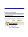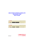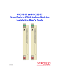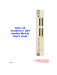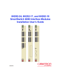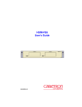
1
2H253-25R SmartSwitch 2200 Installation User’s Guide FAST ETHERNET WORKGROUP SWITCH LED MODE 2 1 RX-TX DPX-SPD 2H253-25R 9034006 PWR CPU RESET COM 4 3 6 5 8 7 10 9 12 11 14 13 16 15 18 17 20 19 22 21 24 23 Only qualified personnel should perform installation procedures. NOTICE Cabletron Systems reserves the right to make changes in specifications and other information contained in this document without prior notice. The reader should in all cases consult Cabletron Systems to determine whether any such changes have been made. The hardware, firmware, or software described in this manual is subject to change without notice. IN NO EVENT SHALL CABLETRON SYSTEMS BE LIABLE FOR ANY INCIDENTAL, INDIRECT, SPECIAL, OR CONSEQUENTIAL DAMAGES WHATSOEVER (INCLUDING BUT NOT LIMITED TO LOST PROFITS) ARISING OUT OF OR RELATED TO THIS MANUAL OR THE INFORMATION CONTAINED IN IT, EVEN IF CABLETRON SYSTEMS HAS BEEN ADVISED OF, KNOWN, OR SHOULD HAVE KNOWN, THE POSSIBILITY OF SUCH DAMAGES. 2000 by Cabletron Systems, Inc., P.O. Box 5005, Rochester, NH 03866-5005 All Rights Reserved Printed in the United States of America Order Number: 9034006 January 2000 Cabletron Systems, LANVIEW, QuickSET, and SecureFast are registered trademarks and SmartSwitch is a trademark of Cabletron Systems, Inc. All other product names mentioned in this manual may be trademarks or registered trademarks of their respective companies. i FCC NOTICE This device complies with Part 15 of the FCC rules. Operation is subject to the following two conditions: (1) this device may not cause harmful interference, and (2) this device must accept any interference received, including interference that may cause undesired operation. NOTE: This equipment has been tested and found to comply with the limits for a Class A digital device, pursuant to Part 15 of the FCC rules. These limits are designed to provide reasonable protection against harmful interference when the equipment is operated in a commercial environment. This equipment uses, generates, and can radiate radio frequency energy and if not installed in accordance with the operator’s manual, may cause harmful interference to radio communications. Operation of this equipment in a residential area is likely to cause interference in which case the user will be required to correct the interference at his own expense. WARNING: Changes or modifications made to this device which are not expressly approved by the party responsible for compliance could void the user’s authority to operate the equipment. INDUSTRY CANADA NOTICE This digital apparatus does not exceed the Class A limits for radio noise emissions from digital apparatus set out in the Radio Interference Regulations of the Canadian Department of Communications. Le présent appareil numérique n’émet pas de bruits radioélectriques dépassant les limites applicables aux appareils numériques de la class A prescrites dans le Règlement sur le brouillage radioélectrique édicté par le ministère des Communications du Canada. VCCI NOTICE This is a Class A product based on the standard of the Voluntary Control Council for Interference by Information Technology Equipment (VCCI). If this equipment is used in a domestic environment, radio disturbance may arise. When such trouble occurs, the user may be required to take corrective actions. ii CABLETRON SYSTEMS, INC. PROGRAM LICENSE AGREEMENT IMPORTANT: THIS LICENSE APPLIES FOR USE OF PRODUCT IN THE FOLLOWING GEOGRAPHICAL REGIONS: CANADA MEXICO CENTRAL AMERICA SOUTH AMERICA BEFORE OPENING OR UTILIZING THE ENCLOSED PRODUCT, CAREFULLY READ THIS LICENSE AGREEMENT. This document is an agreement (“Agreement”) between You, the end user, and Cabletron Systems, Inc. (“Cabletron”) that sets forth your rights and obligations with respect to the Cabletron software program (“Program”) in the package. The Program may be contained in firmware, chips or other media. UTILIZING THE ENCLOSED PRODUCT, YOU ARE AGREEING TO BECOME BOUND BY THE TERMS OF THIS AGREEMENT, WHICH INCLUDES THE LICENSE AND THE LIMITATION OF WARRANTY AND DISCLAIMER OF LIABILITY. IF YOU DO NOT AGREE TO THE TERMS OF THIS AGREEMENT, RETURN THE UNOPENED PRODUCT TO CABLETRON OR YOUR DEALER, IF ANY, WITHIN TEN (10) DAYS FOLLOWING THE DATE OF RECEIPT FOR A FULL REFUND. IF YOU HAVE ANY QUESTIONS ABOUT THIS AGREEMENT, CONTACT CABLETRON SYSTEMS +1- 603-332-9400. Attn: Legal Department. 1. LICENSE. You have the right to use only the one (1) copy of the Program provided in this package subject to the terms and conditions of this License Agreement. You may not copy, reproduce or transmit any part of the Program except as permitted by the Copyright Act of the United States or as authorized in writing by Cabletron. 2. OTHER RESTRICTIONS. You may not reverse engineer, decompile, or disassemble the Program. 3. APPLICABLE LAW. This License Agreement shall be interpreted and governed under the laws and in the state and federal courts of New Hampshire. You accept the personal jurisdiction and venue of the New Hampshire courts. 4. EXPORT REQUIREMENTS. You understand that Cabletron and its Affiliates are subject to regulation by agencies of the U.S. Government, including the U.S. Department of Commerce, which prohibit export or diversion of certain technical products to certain countries, unless a license to export the product is obtained from the U.S. Government or an exception from obtaining such license may be relied upon by the exporting party. If the Program is exported from the United States pursuant to the License Exception CIV under the U.S. Export Administration Regulations, You agree that You are a civil end user of the Program and agree that You will use the Program for civil end uses only and not for military purposes. iii If the Program is exported from the United States pursuant to the License Exception TSR under the U.S. Export Administration Regulations, in addition to the restriction on transfer set forth in Sections 1 or 2 of this Agreement, You agree not to (i) reexport or release the Program, the source code for the Program or technology to a national of a country in Country Groups D:1 or E:2 (Albania, Armenia, Azerbaijan, Belarus, Bulgaria, Cambodia, Cuba, Estonia, Georgia, Iraq, Kazakhstan, Kyrgyzstan, Laos, Latvia, Libya, Lithuania, Moldova, North Korea, the People’s Republic of China, Romania, Russia, Rwanda, Tajikistan, Turkmenistan, Ukraine, Uzbekistan, Vietnam, or such other countries as may be designated by the United States Government), (ii) export to Country Groups D:1 or E:2 (as defined herein) the direct product of the Program or the technology, if such foreign produced direct product is subject to national security controls as identified on the U.S. Commerce Control List, or (iii) if the direct product of the technology is a complete plant o r any major component of a plant, export to Country Groups D:1 or E:2 the direct product of the plant or a major component thereof, if such foreign produced direct product is subject to national security controls as identified on the U.S. Commerce Control List or is subject to State Department controls under the U.S. Munitions List. 5. UNITED STATES GOVERNMENT RESTRICTED RIGHTS. The enclosed Product (i) was developed solely at private expense; (ii) contains “restricted computer software” submitted with restricted rights in accordance with section 52.227-19 (a) through (d) of the Commercial Computer Software-Restricted Rights Clause and its successors, and (iii) in all respects is proprietary data belonging to Cabletron and/or its suppliers. For Department of Defense units, the Product is considered commercial computer software in accordance with DFARS section 227.7202-3 and its successors, and use, duplication, or disclosure by the Government is subject to restrictions set forth herein. 6. EXCLUSION OF WARRANTY. Except as may be specifically provided by Cabletron in writing, Cabletron makes no warranty, expressed or implied, concerning the Program (including its documentation and media). CABLETRON DISCLAIMS ALL WARRANTIES, OTHER THAN THOSE SUPPLIED TO YOU BY CABLETRON IN WRITING, EITHER EXPRESS OR IMPLIED, INCLUDING BUT NOT LIMITED TO IMPLIED WARRANTIES OF MERCHANTABILITY AND FITNESS FOR A PARTICULAR PURPOSE, WITH RESPECT TO THE PROGRAM, THE ACCOMPANYING WRITTEN MATERIALS, AND ANY ACCOMPANYING HARDWARE. 7. NO LIABILITY FOR CONSEQUENTIAL DAMAGES. IN NO EVENT SHALL CABLETRON OR ITS SUPPLIERS BE LIABLE FOR ANY DAMAGES WHATSOEVER (INCLUDING, WITHOUT LIMITATION, DAMAGES FOR LOSS OF BUSINESS, PROFITS, BUSINESS INTERRUPTION, LOSS OF BUSINESS INFORMATION, SPECIAL, INCIDENTAL, CONSEQUENTIAL, OR RELIANCE DAMAGES, OR OTHER LOSS) ARISING OUT OF THE USE OR INABILITY TO USE THIS CABLETRON PRODUCT, EVEN IF CABLETRON HAS BEEN ADVISED OF THE POSSIBILITY OF SUCH DAMAGES. BECAUSE SOME STATES DO NOT ALLOW THE EXCLUSION OR LIMITATION OF LIABILITY FOR CONSEQUENTIAL OR INCIDENTAL DAMAGES, OR IN THE DURATION OR LIMITATION OF IMPLIED WARRANTIES IN SOME INSTANCES, THE ABOVE LIMITATION AND EXCLUSIONS MAY NOT APPLY TO YOU. iv CABLETRON SYSTEMS SALES AND SERVICE, INC. PROGRAM LICENSE AGREEMENT IMPORTANT: THIS LICENSE APPLIES FOR USE OF PRODUCT IN THE UNITED STATES OF AMERICA AND BY UNITED STATES OF AMERICA GOVERNMENT END USERS. BEFORE OPENING OR UTILIZING THE ENCLOSED PRODUCT, CAREFULLY READ THIS LICENSE AGREEMENT. This document is an agreement (“Agreement”) between You, the end user, and Cabletron Systems Sales and Service, Inc. (“Cabletron”) that sets forth your rights and obligations with respect to the Cabletron software program (“Program”) in the package. The Program may be contained in firmware, chips or other media. UTILIZING THE ENCLOSED PRODUCT, YOU ARE AGREEING TO BECOME BOUND BY THE TERMS OF THIS AGREEMENT, WHICH INCLUDES THE LICENSE AND THE LIMITATION OF WARRANTY AND DISCLAIMER OF LIABILITY. IF YOU DO NOT AGREE TO THE TERMS OF THIS AGREEMENT, RETURN THE UNOPENED PRODUCT TO CABLETRON OR YOUR DEALER, IF ANY, WITHIN TEN (10) DAYS FOLLOWING THE DATE OF RECEIPT FOR A FULL REFUND. IF YOU HAVE ANY QUESTIONS ABOUT THIS AGREEMENT, CONTACT CABLETRON SYSTEMS +1- 603-332-9400. Attn: Legal Department. 1. LICENSE. You have the right to use only the one (1) copy of the Program provided in this package subject to the terms and conditions of this License Agreement. You may not copy, reproduce or transmit any part of the Program except as permitted by the Copyright Act of the United States or as authorized in writing by Cabletron. 2. OTHER RESTRICTIONS. You may not reverse engineer, decompile, or disassemble the Program. 3. APPLICABLE LAW. This License Agreement shall be interpreted and governed under the laws and in the state and federal courts of New Hampshire. You accept the personal jurisdiction and venue of the New Hampshire courts. 4. EXPORT REQUIREMENTS. You understand that Cabletron and its Affiliates are subject to regulation by agencies of the U.S. Government, including the U.S. Department of Commerce, which prohibit export or diversion of certain technical products to certain countries, unless a license to export the product is obtained from the U.S. Government or an exception from obtaining such license may be relied upon by the exporting party. If the Program is exported from the United States pursuant to the License Exception CIV under the U.S. Export Administration Regulations, You agree that You are a civil end user of the Program and agree that You will use the Program for civil end uses only and not for military purposes. If the Program is exported from the United States pursuant to the License Exception TSR under the U.S. Export Administration Regulations, in addition to the restriction on transfer set forth in Sections 1 or 2 of this Agreement, You agree not to (i) reexport or release the Program, the source code for the Program or technology to a national of a country in Country Groups D:1 or E:2 (Albania, Armenia, Azerbaijan, Belarus, Bulgaria, Cambodia, Cuba, Estonia, Georgia, Iraq, Kazakhstan, Kyrgyzstan, Laos, Latvia, Libya, Lithuania, Moldova, North Korea, the People’s Republic of China, Romania, Russia, Rwanda, Tajikistan, Turkmenistan, Ukraine, Uzbekistan, Vietnam, or such other countries as may be designated by the United States Government), (ii) export to Country Groups D:1 or E:2 (as defined herein) the direct product of the Program or the technology, if such foreign produced direct product is subject to national security controls as identified on the U.S. Commerce Control List, or (iii) if the direct product of the technology is a complete plant o r any major component of a plant, export to Country Groups D:1 or E:2 the direct product of the plant or a major component thereof, if such foreign produced direct product is subject to national security controls as identified on the U.S. Commerce Control List or is subject to State Department controls under the U.S. Munitions List. v 5. UNITED STATES GOVERNMENT RESTRICTED RIGHTS. The enclosed Product (i) was developed solely at private expense; (ii) contains “restricted computer software” submitted with restricted rights in accordance with section 52.227-19 (a) through (d) of the Commercial Computer Software-Restricted Rights Clause and its successors, and (iii) in all respects is proprietary data belonging to Cabletron and/or its suppliers. For Department of Defense units, the Product is considered commercial computer software in accordance with DFARS section 227.7202-3 and its successors, and use, duplication, or disclosure by the Government is subject to restrictions set forth herein. 6. EXCLUSION OF WARRANTY. Except as may be specifically provided by Cabletron in writing, Cabletron makes no warranty, expressed or implied, concerning the Program (including its documentation and media). CABLETRON DISCLAIMS ALL WARRANTIES, OTHER THAN THOSE SUPPLIED TO YOU BY CABLETRON IN WRITING, EITHER EXPRESS OR IMPLIED, INCLUDING BUT NOT LIMITED TO IMPLIED WARRANTIES OF MERCHANTABILITY AND FITNESS FOR A PARTICULAR PURPOSE, WITH RESPECT TO THE PROGRAM, THE ACCOMPANYING WRITTEN MATERIALS, AND ANY ACCOMPANYING HARDWARE. 7. NO LIABILITY FOR CONSEQUENTIAL DAMAGES. IN NO EVENT SHALL CABLETRON OR ITS SUPPLIERS BE LIABLE FOR ANY DAMAGES WHATSOEVER (INCLUDING, WITHOUT LIMITATION, DAMAGES FOR LOSS OF BUSINESS, PROFITS, BUSINESS INTERRUPTION, LOSS OF BUSINESS INFORMATION, SPECIAL, INCIDENTAL, CONSEQUENTIAL, OR RELIANCE DAMAGES, OR OTHER LOSS) ARISING OUT OF THE USE OR INABILITY TO USE THIS CABLETRON PRODUCT, EVEN IF CABLETRON HAS BEEN ADVISED OF THE POSSIBILITY OF SUCH DAMAGES. BECAUSE SOME STATES DO NOT ALLOW THE EXCLUSION OR LIMITATION OF LIABILITY FOR CONSEQUENTIAL OR INCIDENTAL DAMAGES, OR IN THE DURATION OR LIMITATION OF IMPLIED WARRANTIES IN SOME INSTANCES, THE ABOVE LIMITATION AND EXCLUSIONS MAY NOT APPLY TO YOU. vi CABLETRON SYSTEMS LIMITED PROGRAM LICENSE AGREEMENT IMPORTANT: THIS LICENSE APPLIES FOR THE USE OF THE PRODUCT IN THE FOLLOWING GEOGRAPHICAL REGIONS: EUROPE MIDDLE EAST AFRICA ASIA AUSTRALIA PACIFIC RIM BEFORE OPENING OR UTILIZING THE ENCLOSED PRODUCT, CAREFULLY READ THIS LICENSE AGREEMENT. This document is an agreement (“Agreement”) between You, the end user, and Cabletron Systems Limited (“Cabletron”) that sets forth your rights and obligations with respect to the Cabletron software program (“Program”) in the package. The Program may be contained in firmware, chips or other media. UTILIZING THE ENCLOSED PRODUCT, YOU ARE AGREEING TO BECOME BOUND BY THE TERMS OF THIS AGREEMENT, WHICH INCLUDES THE LICENSE AND THE LIMITATION OF WARRANTY AND DISCLAIMER OF LIABILITY. IF YOU DO NOT AGREE TO THE TERMS OF THIS AGREEMENT, RETURN THE UNOPENED PRODUCT TO CABLETRON OR YOUR DEALER, IF ANY, WITHIN TEN (10) DAYS FOLLOWING THE DATE OF RECEIPT FOR A FULL REFUND. IF YOU HAVE ANY QUESTIONS ABOUT THIS AGREEMENT, CONTACT CABLETRON SYSTEMS +1- 603-332-9400. Attn: Legal Department. 1. LICENSE. You have the right to use only the one (1) copy of the Program provided in this package subject to the terms and conditions of this License Agreement. You may not copy, reproduce or transmit any part of the Program except as permitted by the Copyright Act of the United States or as authorized in writing by Cabletron. 2. OTHER RESTRICTIONS. You may not reverse engineer, decompile, or disassemble the Program. 3. APPLICABLE LAW. This License Agreement shall be governed in accordance with English law. The English courts shall have exclusive jurisdiction in the event of any disputes. 4. EXPORT REQUIREMENTS. You understand that Cabletron and its Affiliates are subject to regulation by agencies of the U.S. Government, including the U.S. Department of Commerce, which prohibit export or diversion of certain technical products to certain countries, unless a license to export the product is obtained from the U.S. Government or an exception from obtaining such license may be relied upon by the exporting party. If the Program is exported from the United States pursuant to the License Exception CIV under the U.S. Export Administration Regulations, You agree that You are a civil end user of the Program and agree that You will use the Program for civil end uses only and not for military purposes. vii If the Program is exported from the United States pursuant to the License Exception TSR under the U.S. Export Administration Regulations, in addition to the restriction on transfer set forth in Sections 1 or 2 of this Agreement, You agree not to (i) reexport or release the Program, the source code for the Program or technology to a national of a country in Country Groups D:1 or E:2 (Albania, Armenia, Azerbaijan, Belarus, Bulgaria, Cambodia, Cuba, Estonia, Georgia, Iraq, Kazakhstan, Kyrgyzstan, Laos, Latvia, Libya, Lithuania, Moldova, North Korea, the People’s Republic of China, Romania, Russia, Rwanda, Tajikistan, Turkmenistan, Ukraine, Uzbekistan, Vietnam, or such other countries as may be designated by the United States Government), (ii) export to Country Groups D:1 or E:2 (as defined herein) the direct product of the Program or the technology, if such foreign produced direct product is subject to national security controls as identified on the U.S. Commerce Control List, or (iii) if the direct product of the technology is a complete plant o r any major component of a plant, export to Country Groups D:1 or E:2 the direct product of the plant or a major component thereof, if such foreign produced direct product is subject to national security controls as identified on the U.S. Commerce Control List or is subject to State Department controls under the U.S. Munitions List. 5. UNITED STATES GOVERNMENT RESTRICTED RIGHTS. The enclosed Product (i) was developed solely at private expense; (ii) contains “restricted computer software” submitted with restricted rights in accordance with section 52.227-19 (a) through (d) of the Commercial Computer Software-Restricted Rights Clause and its successors, and (iii) in all respects is proprietary data belonging to Cabletron and/or its suppliers. For Department of Defense units, the Product is considered commercial computer software in accordance with DFARS section 227.7202-3 and its successors, and use, duplication, or disclosure by the Government is subject to restrictions set forth herein. 6. EXCLUSION OF WARRANTY. Except as may be specifically provided by Cabletron in writing, Cabletron makes no warranty, expressed or implied, concerning the Program (including its documentation and media). CABLETRON DISCLAIMS ALL WARRANTIES, OTHER THAN THOSE SUPPLIED TO YOU BY CABLETRON IN WRITING, EITHER EXPRESS OR IMPLIED, INCLUDING BUT NOT LIMITED TO IMPLIED WARRANTIES OF MERCHANTABILITY AND FITNESS FOR A PARTICULAR PURPOSE, WITH RESPECT TO THE PROGRAM, THE ACCOMPANYING WRITTEN MATERIALS, AND ANY ACCOMPANYING HARDWARE. 7. NO LIABILITY FOR CONSEQUENTIAL DAMAGES. IN NO EVENT SHALL CABLETRON OR ITS SUPPLIERS BE LIABLE FOR ANY DAMAGES WHATSOEVER (INCLUDING, WITHOUT LIMITATION, DAMAGES FOR LOSS OF BUSINESS, PROFITS, BUSINESS INTERRUPTION, LOSS OF BUSINESS INFORMATION, SPECIAL, INCIDENTAL, CONSEQUENTIAL, OR RELIANCE DAMAGES, OR OTHER LOSS) ARISING OUT OF THE USE OR INABILITY TO USE THIS CABLETRON PRODUCT, EVEN IF CABLETRON HAS BEEN ADVISED OF THE POSSIBILITY OF SUCH DAMAGES. BECAUSE SOME STATES DO NOT ALLOW THE EXCLUSION OR LIMITATION OF LIABILITY FOR CONSEQUENTIAL OR INCIDENTAL DAMAGES, OR IN THE DURATION OR LIMITATION OF IMPLIED WARRANTIES IN SOME INSTANCES, THE ABOVE LIMITATION AND EXCLUSIONS MAY NOT APPLY TO YOU. viii DECLARATION OF CONFORMITY Application of Council Directive(s): Manufacturer’s Name: Manufacturer’s Address: European Representative Name: European Representative Address: Conformance to Directive(s)/Product Standards: Equipment Type/Environment: 89/336/EEC 73/23/EEC Cabletron Systems, Inc. 35 Industrial Way PO Box 5005 Rochester, NH 03867 Mr. J. Solari Cabletron Systems Limited Nexus House, Newbury Business Park London Road, Newbury Berkshire RG14 2PZ, England EC Directive 89/336/EEC EC Directive 73/23/EEC EN 55022 EN 50082-1 EN 60950 Networking Equipment, for use in a Commercial or Light Industrial Environment. We the undersigned, hereby declare, under our sole responsibility, that the equipment packaged with this notice conforms to the above directives. Manufacturer Legal Representative in Europe Mr. Ronald Fotino ___________________________________ Full Name Mr. J. Solari ___________________________________ Full Name Compliance Engineering Manager ___________________________________ Managing Director - E.M.E.A. ___________________________________ Title Title Rochester, NH, USA ___________________________________ Location Newbury, Berkshire, England ___________________________________ Location ix x Contents Figures .......................................................................................................................................... xiii Tables............................................................................................................................................xiv ABOUT THIS GUIDE Using This Guide............................................................................................................xv Structure of This Guide ..................................................................................................xv Related Documents.......................................................................................................xvi Document Conventions................................................................................................ xvii 1 INTRODUCTION 1.1 1.2 2 Overview ......................................................................................................... 1-1 1.1.1 Connectivity .................................................................................... 1-2 1.1.2 Auto-Negotiation ............................................................................. 1-2 1.1.3 Runtime IP Address Discovery ....................................................... 1-3 1.1.4 Full Duplex Switched Ethernet........................................................ 1-3 1.1.5 SmartTrunk ..................................................................................... 1-3 1.1.6 Remote Monitoring (RMON) ........................................................... 1-4 1.1.7 Broadcast Suppression................................................................... 1-4 1.1.8 Port/VLAN Redirect Functions ........................................................ 1-4 1.1.9 Rate Limiting ................................................................................... 1-5 1.1.10 Flow Control.................................................................................... 1-5 1.1.11 GARP Switch Operation ................................................................. 1-6 1.1.12 802.1 Port Priority ........................................................................... 1-6 1.1.13 Management ................................................................................... 1-6 1.1.14 Switching Options ........................................................................... 1-6 1.1.15 Optional HSIMs and VHSIMs.......................................................... 1-7 1.1.16 Standards Compatibility .................................................................. 1-7 1.1.17 Year 2000 Compliant ...................................................................... 1-7 1.1.18 LANVIEW Diagnostic LEDs ............................................................ 1-7 Getting Help .................................................................................................... 1-8 NETWORK REQUIREMENTS 2.1 2.2 2.3 SmartTrunk ..................................................................................................... 2-1 10BASE-T Network ......................................................................................... 2-1 100BASE-TX Network..................................................................................... 2-2 xi 3 INSTALLATION 3.1 3.2 3.3 3.4 3.5 4 TROUBLESHOOTING 4.1 4.2 4.3 A B.5 xii Device Specifications ......................................................................................A-1 Physical Properties .........................................................................................A-1 Electrical Specifications ..................................................................................A-2 Environmental Requirements..........................................................................A-2 Input/Output Ports ...........................................................................................A-2 COM Port Pinout Assignments .......................................................................A-3 Regulatory Compliance...................................................................................A-3 OPTIONAL INSTALLATIONS AND MODE SWITCH BANK SETTINGS B.1 B.2 B.3 B.4 INDEX Using LANVIEW.............................................................................................. 4-1 Troubleshooting Checklist............................................................................... 4-5 Using the RESET Button................................................................................. 4-8 SPECIFICATIONS A.1 A.2 A.3 A.4 A.5 A.6 A.7 B Unpacking the Device ..................................................................................... 3-1 Installing Options............................................................................................. 3-2 Installing the Device ........................................................................................ 3-2 3.3.1 Tabletop or Shelf Installation .......................................................... 3-3 3.3.2 Rackmount Installation.................................................................... 3-4 3.3.3 Connecting Power........................................................................... 3-7 Connecting to the Network.............................................................................. 3-8 Completing the Installation............................................................................ 3-10 Required Tools................................................................................................B-1 Removing the Chassis Cover..........................................................................B-2 Setting the Mode Switches..............................................................................B-5 SIMM Upgrade ................................................................................................B-6 B.4.1 Locating SIMMs ..............................................................................B-7 B.4.2 Installing the DRAM SIMM..............................................................B-7 Installing Optional HSIM or VHSIM Interface Modules ...................................B-9 Figures Figure 1-1 3-1 3-2 3-3 3-4 3-5 3-6 4-1 4-2 B-1 B-2 B-3 B-4 B-5 Page The 2H253-25R SmartSwitch 2200................................................................................. 1-1 Tabletop or Shelf Installation........................................................................................... 3-4 Attaching the Strain-Relief Bracket ................................................................................. 3-5 Attaching the Rackmount Brackets ................................................................................. 3-6 Installing the Device in a Rack ........................................................................................ 3-6 2H253-25R Rear View .................................................................................................... 3-7 Straight Cable Connection .............................................................................................. 3-9 LANVIEW LEDs .............................................................................................................. 4-1 RESET Button ................................................................................................................. 4-8 Removing the Chassis Cover..........................................................................................B-4 Mode Switch Location .....................................................................................................B-5 SIMM Slot Locations .......................................................................................................B-7 Installing the DRAM.........................................................................................................B-8 HSIM and VHSIM Connector Locations ..........................................................................B-9 xiii Tables Table Page 3-1 Contents of 2H253-25R Carton........................................................................................ 3-2 4-1 LANVIEW LEDs .............................................................................................................. 4-2 4-2 Troubleshooting Checklist ............................................................................................... 4-5 A-1 COM Port Pin Assignments ............................................................................................ A-3 xiv About This Guide Welcome to the 2H253-25R SmartSwitch 2200 Installation User’s Guide. This guide describes the 2H253-25R SmartSwitch 2200 device and provides information concerning network requirements, installation, and troubleshooting. For information about how to use Local Management to configure and manage the 2H253-25R, refer to the Cabletron Systems SmartSwitch Series 2E253, 2H252, 2H253 and 2H258 Local Management User’s Guide. Important Notice Depending on the firmware version used in the 2H253-25R, some features described in this document may not be supported. Refer to the Release Notes shipped with the 2H253-25R to determine which features are supported. USING THIS GUIDE Read through this guide and the SmartSwitch Series 2E253, 2H252, 2H253 and 2H258 Local Management User’s Guide to completely understand the 2H253-25R capabilities and Local Management functions. A general working knowledge of Ethernet and IEEE 802.3 type data communications networks and their physical layer components is helpful when using this device. In this document, the device is referred to as either the “2H253-25R” or the “device”. NOTE STRUCTURE OF THIS GUIDE This guide is organized as follows: Chapter 1, Introduction, provides an overview of the 2H253-25R and its features. Directions for obtaining additional information or help from Cabletron Systems are also included in this chapter. Chapter 2, Network Requirements, explains the network requirements to consider before installing the 2H253-25R. Chapter 3, Installation, provides instructions on how to install the 2H253-25R and connect segments to the device. xv Related Documents Chapter 4, Troubleshooting, describes the function of the LANVIEW LEDs, which can help to quickly diagnose network/operational problems. Appendix A, Specifications, contains information on functionality and operating specifications, connector pinouts, environmental requirements, and physical properties. Appendix B, Optional Installations and Mode Switch Bank Settings, describes how to remove the cover from the device, set the Mode Switch, and shows the location of an optional High Speed Interface Module (HSIM) or Very High Speed Interface Module (VHSIM) when one is installed. RELATED DOCUMENTS The following Cabletron Systems documents may help to set up, control, and manage the 2H253-25R: The following Cabletron Systems documents may help to set up and manage the 2H253-25R: • SmartSwitch Series 2E253, 2H252, 2H253 and 2H258 Local Management User’s Guide • Ethernet Technology Guide • Cabling Guide • SmartTrunk User’s Guide • WAN Series Local Management User’s Guide The following are Cabletron Systems documents associated with optional interface modules: • HSIM-A6DP User’s Guide • HSIM-F6 User’s Guide • HSIM-FE6 User’s Guide • HSIM-W6 Installation Guide • HSIM-W84 Installation Guide • HSIM-W87 User’s Guide • HSIM-G01/G09 User’s Guide • VHSIM-G6 User’s Guide • VHSIM-A6DP User’s Guide xvi Document Conventions The HSIM-W6 Installation Guide, the HSIM-W84 Installation Guide, and the WAN Series Local Management User’s Guide are included on the QuickSET CD-ROM and, along with the other manuals listed above, can be obtained from the World Wide Web in Adobe Acrobat Portable Document Format (PDF) at the following site: http://www.cabletron.com/ NOTE All documentation for the Cabletron Systems SecureFast VLAN Manager software is contained on the VLAN Manager CD-ROM. DOCUMENT CONVENTIONS The guide uses the following conventions: NOTE Note symbol. Calls the reader’s attention to any item of information that may be of special importance. Tip symbol. Conveys helpful hints concerning procedures or actions. TIP ! Caution symbol. Contains information essential to avoid damage to the equipment. CAUTION Electrical Hazard Warning symbol. Warns against an action that could result in personal injury or death due to an electrical hazard. Warning symbol. Warns against an action that could result in personal injury or death. WARNING xvii 1 Introduction This chapter introduces the 2H253-25R SmartSwitch 2200 device and provides information about how to obtain additional support from Cabletron Systems. Important Notice Depending on the firmware version used in the 2H253-25R, some features described in this document may not be supported. Refer to the Release Notes shipped with the 2H253-25R to determine which features are supported. 1.1 OVERVIEW The 2H253-25R (Figure 1-1) is an Ethernet/Fast Ethernet standalone device with two RJ21 front panel connectors (each containing 12 switched ports), and 1 slot for an optional High Speed Interface Module (HSIM) or Very High Speed Interface Module (VHSIM). Port Status LEDs LED MODE Switch HSIM/VHSIM Slot FAST ETHERNET WORKGROUP SWITCH LED MODE 2 1 RX-TX 4 3 6 5 8 7 10 9 12 11 14 13 16 15 18 17 20 19 22 21 24 23 DPX-SPD 2H253-25R PWR CPU RESET COM Reset COM Button Port System LEDs Network Ports 1-24 (Two RJ21 connectors) Figure 1-1 27621-01 The 2H253-25R SmartSwitch 2200 Introduction 1-1 Overview The 2H253-25R is used to connect individual high-bandwidth user devices, such as workstations, or to provide a central switching point for multiple 10/100 Mbps Fast Ethernet segments. The optional HSIMs provide high speed uplinks to networking technologies such as Fast Ethernet, Gigabit Ethernet, Fiber Distributed Data Interface (FDDI), Wide Area Network (WAN), and Asynchronous Transfer Mode (ATM). Some HSIMs can provide additional Fast Ethernet ports in varying media types. The optional VHSIMs provide very high speed uplinks to networking technologies such as Gigabit Ethernet and ATM. The 2H253-25R ports can be configured to control frame traffic in several ways, including prioritizing traffic flow according to protocol type. The 2H253-25R can also be configured to establish Virtual Local Area Networks (VLANs) and control the flow of frames associated with each VLAN according to priority and Ether type. Detailed information about VLANs is provided in the Cabletron Systems 802.1Q VLAN User’s Guide. The 2H253-25R may be used as a tabletop unit or can be installed in a standard 19-inch rack using the supplied rack mounting hardware. The 2H253-25R has two power supplies. The power supplies load share 50% (+/-5%) of the power required by the device. If one power supply fails, the remaining power supply assumes the entire load of the device without interruption to network traffic. Each power supply module supports its own ac input connection, which enables each power supply to be connected to a different ac power circuit. 1.1.1 Connectivity The 2H253-25R connects to Ethernet networks or workstations through two RJ21 ports on the front panel. Each RJ21 connector contains 12, 10/100 Mbps Ethernet ports. These ports are IEEE 802.3 10BASE-T and IEEE 802.3u 100BASE-TX compliant, and they support Category 3 (10-Mbps operation only) and Category 5 Unshielded Twisted Pair cabling. The Category 5 cabling must have an impedance of between 85 and 111 ohms at lengths up to 100 meters. The device also has a slot for an optional HSIM or VHSIM to provide additional connectivity to various networking technologies. 1.1.2 Auto-Negotiation The fixed twisted pair ports (1 through 24) on the 2H253-25R have the ability to auto-negotiate the type of connection required to provide a link to another device. During Auto-Negotiation, two devices automatically exchange information so they know each others operating capabilities. The Auto-Negotiation feature targets the maximum capabilities that can be reached between the two devices. For example, the 2H253-25R can adjust to 100 Mbps when the device on the other end of the connection can also adjust from 10 Mbps to 100 Mbps. If the device on the other end of the connection can only operate at 10 Mbps, then the 2H253-25R simply adjusts to operate at 10 Mbps. 1-2 Introduction Overview When Auto-Negotiation is supported at both ends of a link, the two devices dynamically adjust to full or half duplex operation based on the maximum capability that can be reached between the two devices. If the device connected to the 2H253-25R cannot auto-negotiate, the 2H253-25R operates according to the capabilities of the other device. 1.1.3 Runtime IP Address Discovery This feature enables the 2H253-25R device to automatically accept an IP address from a Boot Strap Protocol (BootP) server on the network without requiring a user to enter an IP address through Local Management. When the device is connected to the network and powered up, Runtime IP Address Discovery (RAD) checks the device for an IP address. If one has not yet been assigned (device IP address set to 0.0.0.0), RAD checks to see if any of the device interfaces have a link. If so, RAD sends out Reverse Address Resolution Protocol (RARP) and BootP requests to obtain an IP address from a BootP server on the network. The RAD requests start at an interval of 1 per second. The interval then doubles after every transmission until an interval of 300 seconds is reached. At this point, the interval remains at 300 seconds. The RAD requests continue until an IP address is received from a RARP or BootP server, or an IP address is entered using Local Management. The 2H253-25R will reboot after RAD is successful. NOTE 1.1.4 Full Duplex Switched Ethernet Each switched Fast Ethernet port on the 2H253-25R supports 10/100 Mbps operation, and can operate in Full Duplex Switched Ethernet (FDSE) mode. FDSE enables each port to provide up to 200 Mbps of bandwidth to connected devices that support FDSE. 1.1.5 SmartTrunk Traditional 802.1D Spanning Tree Bridges only allow one active data path between any two switches; all other parallel data paths are in Standby or Blocking mode. If one interface or path should fail, then the other interface automatically comes out of Blocking mode and forwards all of the traffic. This is fine for redundancy purposes. However, it is not the most efficient use of resources. Introduction 1-3 Overview SmartTrunk, also referred to as SmartTrunking, is Cabletron Systems’ terminology for load balancing or load sharing. SmartTrunk provides the ability to take full advantage of the network’s redundant bandwidth. SmartTrunk divides network traffic across multiple ports in parallel to provide additional throughput. The SmartTrunk application can be used with any of Cabletron Systems’ switch modules (except ATM modules). For more information about SmartTrunk and how to configure it the SmartSwitch device, refer to the Cabletron Systems SmartTrunk User’s Guide. 1.1.6 Remote Monitoring (RMON) The 2H253-25R supports all nine Ethernet RMON groups. The Statistics, Alarms, Events and History groups are enabled on all ports by default. Cabletron Systems RMON Actions is a vendor-specific extension of RMON and provides the ability to set an “Action” on any SNMP MIB variable. The Action can be triggered by any RMON Event and/or Alarm. An example of an Action would be to turn off a MIB-2 interface if a broadcast threshold is crossed. 1.1.7 Broadcast Suppression Broadcast Suppression enables a user to set a desired limit of receive broadcast frames per port/per second to be forwarded out the other ports on the device. Any broadcast frames above this specified limit are dropped. In the event that broadcast frames are being suppressed, multicast and unicast frames continue to be switched. 1.1.8 Port/VLAN Redirect Functions The port redirect function, also referred to as “Port Mirroring,” is a troubleshooting tool used to map traffic from a single source port to a single destination port within the device. This feature allows frames, including those with errors to be copied and sent to an analyzer or RMON probe. The analyzer or RMON probe will see the data as if it were directly connected to the LAN segment of the source port. The VLAN redirect function is similar to the port redirect function except that the frames received by the device are redirected to a designated destination port according to the VLAN classification of the frames received. Multiple VLANs can be directed to the same port. The VLAN redirect function is only supported when the device is operating as an 802.1Q switch. 1-4 Introduction Overview 1.1.9 Rate Limiting The Rate Limiting feature enables the SmartSwitch device to control traffic rates on a per-port, per-priority basis. The network administrator can configure a rate limit (from 100 kbps to 1 Gbs) for a given port with an associated list of IEEE 802.1p priorities (which can include one, some, or all of the eight priority levels defined in 802.1p). Each rate limit is specified as an inbound or an outbound limit. The combined rate of all traffic on the port that matches the listed priorities cannot exceed the programmed limit. If the rate exceeds the defined limit, frames are dropped until the rate falls below the limit. Administrators can configure up to four rate limit rules per port; however, each rule must not include conflicting 802.1p priority values. In order to control traffic inbound and outbound on the same port, two rate limit rules must be configured (one inbound and one outbound). Since the rate limiting operation occurs after the processing of the multi-layer classification rules, the two features can be combined to provide application-aware rate limiting. This traffic rate function is not supported on ports configured as SmartTrunk ports. NOTE For more information about the application of the Traffic Rate function, refer to the SmartSwitch Series 2E253, 2H252, 2H253 and 2H258 Local Management User’s Guide. 1.1.10 Flow Control Flow control is a method of managing the flow of frames between two devices. It ensures that a transmitting device does not overwhelm a receiving device with data. This is accomplished by the transmitting device pausing its transmission while the receiving device processes the frames already received. The 2H253-25R supports the following two types of flow control: • Frame based 802.3x • Back pressure Frame based 802.3x flow control is supported on all Ethernet ports operating in the full duplex mode. Flow control can be enabled or disabled on a port-by-port basis. Back pressure flow control is supported on all Ethernet ports operating in the standard mode of operation. Flow control can be enabled or disabled on a port-by-port basis. Introduction 1-5 Overview 1.1.11 GARP Switch Operation Some or all ports on the switch may be activated to operate under the Generic Attribute Registration Protocol (GARP) applications, GARP VLAN Registration Protocol (GVRP) and/or GARP Multicast Registration Protocol (GMRP). GARP is a protocol, or set of rules, that outlines a mechanism for propagating the port state and/or user information throughout a bridged LAN to keep track of users and VLANs on the network fabric. MAC bridges and end users alike can take part in the registration and de-registration of GARP attributes such as VLAN and multicast group membership. For more details on how GVRP and GMRP handle frames under GARP, and how to configure the switch ports to take advantage of this operation, refer to the SmartSwitch Series 2E253, 2H252, 2H253 and 2H258 Local Management User’s Guide. 1.1.12 802.1 Port Priority The 802.1 port priority is used to assign a default priority to the frames received without priority information in their tag header, map prioritized frames to the appropriate transmit queues, and prioritize frames according to protocol type. The 802.1 port priority is part of the IEEE 802.1D standard. 1.1.13 Management Management of the 2H253-25R is accomplished using SNMP-compliant management tools for in-band Local Management. Out-of-band Local Management is provided through the RJ45 COM port on the front panel using a VT100 terminal or a VT100 terminal emulator. In-band remote management is possible through any SNMP compliant Network Management Software. Local Management described in the SmartSwitch Series 2E253, 2H252, 2H253 and 2H258 Local Management User’s Guide provides the ability to manage the 2H253-25R, and optional HSIMs and VHSIMs that support Ethernet. For information about Local Management for optional non-Ethernet HSIMs or VHSIMs, refer to their respective user’s guide. 1.1.14 Switching Options The 2H253-25R provides 802.1Q switching or SecureFast Switching Virtual Network Services between all of the front panel interfaces including the optional HSIM or VHSIM interface. In the 802.1Q mode (the default mode of operation), the switch functions as an 802.1D switch until VLANs are configured. IEEE 802.1Q switching and SecureFast switching allow migration to Virtual Network technologies without requiring the replacement of existing equipment. 1-6 Introduction Overview 1.1.15 Optional HSIMs and VHSIMs Optional HSIMs and VHSIMs are available from Cabletron Systems for additional connectivity to various networking technologies. The HSIMs and VHSIMs available for the 2H253-25R are listed in the Release Notes shipped with the device. 1.1.16 Standards Compatibility The 2H253-25R is fully compliant with the IEEE 802.3, 802.3u, 802.3x, 802.1D, and 802.1Q standards. The 2H253-25R provides IEEE 802.1D Spanning Tree Algorithm (STA) support to enhance the overall reliability of the network and protect against “loop” conditions. The 2H253-25R supports a wide variety of industry standard MIBs including RFC 1213 (MIB II), RFC 1757 (RMON), RFC 1493 (Bridge MIB), RFC 1354 (FIB MIB), and RFC 1190 (Path MTU Discovery). A full suite of Cabletron Systems Enterprise MIBs provide a wide array of statistical information to enhance troubleshooting. For information on how to extract and compile individual MIBs, contact Cabletron Systems. 1.1.17 Year 2000 Compliant The 2H253-25R has an internal clock that can maintain the current time and date beyond the year 1999. 1.1.18 LANVIEW Diagnostic LEDs LANVIEW diagnostic LEDs serve as an important troubleshooting aid by providing an easy way to observe the status of individual ports and overall network operations. Introduction 1-7 Getting Help 1.2 GETTING HELP For additional support related to this device or document, contact Cabletron Systems using one of the following methods: World Wide Web http://www.cabletron.com/ Phone (603) 332-9400 Internet mail [email protected] FTP ftp://ftp.cabletron.com/ Login anonymous Password your email address To send comments or suggestions concerning this document, contact the Cabletron Systems Technical Writing Department via the following email address: [email protected] Make sure to include the document Part Number in the email message. Before calling Cabletron Systems, have the following information ready: • Your Cabletron Systems service contract number • A description of the failure • A description of any action(s) already taken to resolve the problem (e.g., changing mode switches, rebooting the unit, etc.) • The serial and revision numbers of all involved Cabletron Systems products in the network • A description of your network environment (layout, cable type, etc.) • Network load and frame size at the time of trouble (if known) • The device history (i.e., have you returned the device before, is this a recurring problem, etc.) • Any previous Return Material Authorization (RMA) numbers 1-8 Introduction 2 Network Requirements Before installing the 2H253-25R, review the requirements and specifications referred to in this chapter concerning the following: • SmartTrunk (Section 2.1) • 10BASE-T Twisted Pair Network (Section 2.2) • 100BASE-TX Twisted Pair Network (Section 2.3) The network installation must meet the requirements to ensure satisfactory performance of this equipment. Failure to do so will produce poor network performance. NOTE 2.1 The Cabletron Systems SmartTrunk User’s Guide and Cabling Guide referred to in the following sections can be found on the Cabletron Systems World Wide Web site: http://www.cabletron.com/ SmartTrunk To connect the 2H253-25R to a network so it can take advantage of the SmartTrunk feature, there are certain rules concerning port connections and configurations that must be followed for proper operation. Refer to the Cabletron Systems SmartTrunk User’s Guide for additional information. 2.2 10BASE-T NETWORK When connecting a 10BASE-T segment to any of the 2H253-25R ports (1 through 24), ensure that the network meets the Ethernet network requirements of the IEEE 802.3 standard for 10BASE-T. The ports support Category 3 UTP cabling when connected to a 10BASE-T segment. Refer to the Cabletron Systems Cabling Guide for details. NOTE If a port is to operate at 10 and 100 Mbps, Category 5 cabling must be used. Refer to Section 2.3 for information about 100BASE-TX networks and cabling. Network Requirements 2-1 100BASE-TX Network 2.3 100BASE-TX NETWORK The two RJ21 connectors on the front panel of the 2H253-25R each provide 12 fixed ports (ports 1 through 24) that support Category 5 UTP cabling. The device at the other end of the twisted pair segment must meet IEEE 802.3u 100BASE-TX Fast Ethernet network requirements for the devices to operate at 100 Mbps. Refer to the Cabletron Systems Cabling Guide for details. NOTE The fixed ports of the 2H253-25R support Category 5 UTP cabling that has an impedance between 85 and 111 ohms. The 2H253-25R is capable of operating at either 10 or 100 Mbps. When the port is configured for Auto-Negotiation, the 2H253-25R automatically senses the speed of the other device and adjusts its speed accordingly. 2-2 Network Requirements 3 Installation Only qualified personnel should install the 2H253-25R. NOTE Read the Release Notes shipped with the device to check for any exceptions to the supported features and operation documented in this guide. This chapter provides the instructions required to install the 2H253-25R. A Phillips screwdriver is required to install options into the device or install the device into a rack. Follow the order of the sections listed below to correctly install the device. • Unpacking the Device (Section 3.1) • Installing Options (Section 3.2) • Installing the Device (on a shelf or tabletop, or into a standard rack) (Section 3.3) • Connecting to the Network (Section 3.4) • Completing the Installation (Section 3.5) 3.1 UNPACKING THE DEVICE Unpack the device as follows: 1. Open the box and remove the packing material protecting the 2H253-25R. 2. Verify the contents of the carton as listed in Table 3-1. Installation 3-1 Installing Options Table 3-1 Contents of 2H253-25R Carton Item Quantity 2H253-25R 1 Antistatic Wrist Strap 1 Console Cable Kit 1 Rackmount Kit 1 Strain-Relief Bracket 1 Manual Accessory Kit 1 Power Cord 2 3. Remove the tape seal on the non-conductive bag to remove the 2H253-25R. 4. Perform a visual inspection of the device for any signs of physical damage. Contact Cabletron Systems if there are any signs of damage. Refer to Section 1.2 for details. 3.2 INSTALLING OPTIONS Install any optional equipment before proceeding to Section 3.3. NOTE If the 2H253-25R is to be installed with an optional HSIM or VHSIM, refer to the user’s guide of that device for the installation instructions. 3.3 INSTALLING THE DEVICE The 2H253-25R may be installed on a tabletop, shelf, or in a 19-inch rack. Section 3.3.1 describes a tabletop or shelf installation and Section 3.3.2 describes the rackmount installation. To prevent possible personal injury and/or damage to the unit, do NOT connect power to the 2H253-25R until instructed to do so. 3-2 Installation Installing the Device 3.3.1 Tabletop or Shelf Installation The following two subsections provide guidelines for installation on a tabletop or shelf. Guidelines for Tabletop and Shelf Installations Tabletop and shelf installations must be within reach of the network cabling and meet the requirements listed below: • Locate the 2H253-25R within seven feet of an appropriately grounded power receptacle that meets the power supply requirements listed in Appendix A. • In a shelf installation, the shelf must support 13.5 kg (30 lb) of static weight for each 2H253-25R. • Maintain a temperature of between 5°C (41°F) and 40°C (104°F) at the installation site with fluctuations of less than 10°C (18°F) per hour. ! To ensure proper ventilation and prevent overheating, leave a minimum clearance space of 5.1 cm (2.0 in) at the left, right, and rear of the 2H253-25R. CAUTION • Maintain a 2-inch clearance from the left, right, and rear sides of the device to provide adequate ventilation. Installation For a tabletop or shelf installation, locate the 2H253-25R within seven feet of its power source and on an unrestricted free surface area as shown in Figure 3-1. Proceed to Section 3.3.3 for power connection instructions. Installation 3-3 Installing the Device C B FAST ETHERNET WORKGROUP SWITCH LED MODE 2 1 RX-TX 4 3 6 5 8 7 10 9 12 11 14 13 16 15 18 17 20 19 22 21 24 23 DPX-SPD A 2H253-25R PWR CPU RESET COM D A = 15 cm (6 in) B = 57 cm (22.5 in) C = 53 cm (21 in) D = 213 cm (7 ft) 2762-02 Figure 3-1 3.3.2 Tabletop or Shelf Installation Rackmount Installation To install the 2H253-25R in a 19-inch rack, Cabletron Systems includes a strain-relief bracket for cable management and an accessory kit containing the rackmount brackets, and mounting screws to attach the rackmount brackets and strain-relief bracket. Guidelines for the Rackmount Installation The installation site must be within reach of the network cabling and meet the requirements listed below: • An appropriate grounded power receptacle must be located within seven feet of the location. • Maintain a temperature of between 5°C (41°F) and 40°C (104°F) at the installation site with fluctuations of less than 10°C (18°F) per hour. ! To ensure proper ventilation and prevent overheating, leave a minimum clearance space of 5.1 cm (2.0 in) at the left, right, and rear of the 2H253-25R. CAUTION WARNING 3-4 Before installing the 2H253-25R into a rack, ensure that the rack supports the device(s) without compromising the stability of the rack. Otherwise, personal injury and/or equipment damage may result. Installation Installing the Device Installation Rack mounting the 2H253-25R involves the following: • Attaching the strain-relief bracket • Rack mounting the 2H253-25R (attaching the mounting brackets and fastening the device to the rack) Attaching the Strain-Relief Bracket Attach the strain-relief bracket to the 2H253-25R as follows: 1. Locate the strain-relief bracket and four 8-32 x 5/16-inch pan-head screws in the rackmount kit. ! CAUTION Do not attempt to attach the strain-relief bracket with screws other than the 8-32 x 5/16-inch screws included with the 2H253-25R. Use of longer screws may damage the unit. 2. Place the 2H253-25R upside down (as shown in Figure 3-2) on a clean flat surface. Then attach the strain-relief bracket to the bottom of the 2H253-25R using the four 8-32 x 5/16-inch pan-head screws. Strain-Relief Bracket Screws Strain-Relief Bracket 2H253-25R COM PWR CPU RESET DPX-SPD RX-TX LED MODE 2 1 4 3 6 5 8 7 10 9 12 11 14 13 16 15 18 17 20 19 22 21 24 23 FAST ETHERNET WORKGROUP SWITCH 2762-03 Figure 3-2 Attaching the Strain-Relief Bracket Installation 3-5 Installing the Device Rack Mounting the 2H253-25R Proceed as follows to install the 2H253-25R into a 19-inch rack: 1. There are several mounting holes in the rackmount brackets and the bottom of the chassis so that each mounting bracket may be adjusted forward or backward to mount the device further into, or out of the rack, depending on the installation requirements. Position the rackmount brackets over the appropriate holes. 2. Locate the four 6-32 x 1/4-inch flathead screws in the rackmount kit. Use these screws to attach the rackmount brackets to the bottom of the 2H253-25R as shown in Figure 3-3. Rackmount Bracket Screws Rackmount Bracket 2H253-25R COM TELCO CONSOLE PWR CPU RESET DPX-SPD RX-TX LED MODE 2 1 4 3 6 5 8 7 10 9 12 11 16 15 14 13 18 17 20 19 22 21 24 23 FAST ETHERNET WORKGROUP SWITCH 27621-04 Figure 3-3 Attaching the Rackmount Brackets 3. With the mounting brackets attached, position the 2H253-25R between the vertical frame members of the 19-inch rack and fasten it securely with mounting screws as shown in Figure 3-4. FAST ETHERNET WORKGROUP SWITCH LED MODE 2 1 RX-TX 4 3 6 5 8 7 10 9 12 11 14 13 16 15 18 17 20 19 22 21 24 23 DPX-SPD 2H253-25R PWR CPU RESET COM Screws 19-Inch Rack Figure 3-4 3-6 Installation Installing the Device in a Rack 27621-05 Installing the Device 3.3.3 NOTE Connecting Power The two power supplies in the 2H253-25R have automatic voltage sensing that allows connection to power sources ranging from 100–125 Vac, 2.5 A or 200–240 Vac, 1.25 A, 50/60 Hz. To connect the 2H253-25R to the power sources, proceed as follows: 1. Plug each power cord into a grounded wall outlet, see Figure 3-5. To take advantage of the load sharing and redundancy capabilities, each power cord must be plugged into a separate dedicated ac outlet. The POWER LED turns ON (green) and the CPU LED alternates between green and amber during boot up. It takes approximately one minute for the 2H253-25R to boot up. NOTE If the power-up sequence is interrupted on this device, or if optional hardware has been installed or removed, this device may run an extended diagnostics sequence that may take up to five minutes to complete. Primary Redundant AC outlets are on separate circuits Figure 3-5 26001-06 2H253-25R Rear View Installation 3-7 Connecting to the Network 2. Observe the LANVIEW LEDs. After a successful boot, the PWR LED turns ON (green). If the PWR LED is amber, there is no power redundancy. Check the power cord connections and the power source. If there are no problems with the power cord connections or power source and the PWR LED is still amber, contact Cabletron Systems for support. Refer to Section 1.2 for details. 3.4 CONNECTING TO THE NETWORK This section provides the procedures for connecting unshielded twisted pair (UTP) segments from the network or other devices to the 2H253-25R. To make connections to an optional HSIM or VHSIM installed in the HSIM/VHSIM slot of the 2H253-25R, refer to the associated user’s guide for the HSIM or VHSIM. NOTE If the 2H253-25R is being installed in a network using SmartTrunking, there are rules concerning the network cable and port configurations that must be followed for SmartTrunking to operate properly. Before connecting the cables, refer to the Cabletron Systems SmartTrunk User’s Guide for the configuration information. Each of the two RJ21 connectors on the front panel have 12 UTP port connections. These ports (1 through 24) are 10/100 ports with internal crossovers. When connecting a workstation, use a straight-through cable. When connecting networking devices, such as another bridge, repeater, or router, use a crossover cable. NOTE If a port is connected to a 10-Mbps segment, Category 3 Unshielded Twisted Pair (UTP) cable is sufficient to use. However, if the segment is to carry 10- or 100-Mbps transmissions, use only Category 5 UTP cabling that has an impedance of between 85 and 111 ohms. To connect an RJ21, proceed as follows: 1. Ensure that the device connected to the other end of the segment is powered on. 2. If using an RJ21 straight connector, plug it into the appropriate RJ21 port as shown in Figure 3-6. 3-8 Installation Connecting to the Network Receive (RX) LED MODE LED MODE Switch in RX–TX position RX-TX Transmit (TX) DPX-SPD P SWITCH GROU RNET WORK FAST ETHE 2 1 LED MODE 4 3 6 5 8 7 10 9 12 11 14 13 16 15 18 17 20 19 22 21 24 23 RX-TX DPX-SPD PWR CPU RESET COM 2H253-25R Screw LED MODE Switch RJ21 Screw 2762-07 Figure 3-6 Straight Cable Connection 3. Tighten the two screws on the RJ21 straight cable connector to secure it to the device. NOTE The cable pinouts for a 25-pair cable (RJ21) can be found in the Cabletron Systems Cabling Guide. Refer to Section 1.2 for details on how to obtain this document. 4. Verify that a link exists on each twisted pair segment of the RJ21 connector by checking that the associated port RX LED is on (flashing amber, blinking green, or solid green). If the RX LED is off and the TX LED is not blinking amber, perform the following steps until it is on: a. Verify that the LED switch located near the COM port of the device is in the left-most position (RX and TX LED indicators) as shown in Figure 3-6. b. Verify that the UTP cabling used is Category 3 (for 10BASE-T) or Category 5 (for 10BASE-T or 100BASE-TX). The Category 5 cabling must have an impedance of between 85 and 111 ohms. NOTE If a port is to operate at 10 and 100 Mbps, Category 5 cabling must be used. Refer to Section 2.3 for information about 100BASE-TX networks and cabling. Installation 3-9 Completing the Installation c. Verify that the 100BASE-TX device at the other end of the twisted pair segment is powered up. d. Check the cable for continuity. e. If a link is not established, contact Cabletron Systems for technical support. Refer to Section 1.2 for details. 5. Repeat steps 1 through 4 above, until all connections have been made. 3.5 COMPLETING THE INSTALLATION After installing the 2H253-25R and any optional HSIM or VHSIM, and making the connections to the network, proceed as follows: 1. Secure the cables by running the cables along the strain-relief bracket and tying them to the strain-relief bracket using cable ties. 2. The 2H253-25R is now ready to be configured through Local Management. Refer to the SmartSwitch Series 2E253, 2H252, 2H253, and 2H258 Local Management User’s Guide for information on how to access and use Local Management. 3-10 Installation 4 Troubleshooting This chapter provides information concerning the following: • Using LANVIEW (Section 4.1) • Troubleshooting Checklist (Section 4.2) • Using the RESET Button (Section 4.3) 4.1 USING LANVIEW The 2H253-25R uses Cabletron Systems’ built-in visual diagnostic and status monitoring system called LANVIEW. The LANVIEW LEDs (Figure 4-1) allow quick observation of the network status to aid in diagnosing network problems. Receive (RX) LED MODE RX-TX A LED MODE RX-TX B DPX-SPD Full Duplex Status DPX-SPD Transmit (TX) Speed Status FAST ETHERNET WORKGROUP SWITCH LED MODE 2 1 RX-TX 4 3 6 5 8 7 10 9 12 11 14 13 16 15 18 17 20 19 22 21 24 23 DPX-SPD 2H253-25R PWR CPU RESET COM PWR CPU A LED functions when LED MODE switch is in the RX-TX position. This is the default switch setting. B LED functions when LED MODE switch is in the DPX-SPD position. 2762-09 Figure 4-1 LANVIEW LEDs Troubleshooting 4-1 Using LANVIEW The LED MODE switch is located on the front panel of the 2H253-25R as shown in Figure 4-1. This switch enables the user to change the function of the port LEDs. When the LED MODE switch is moved to the left, the LEDs indicate the receive (RX) and transmit (TX) status of the respective fixed ports (ports 1 through 24). When the LED MODE switch is moved to the right, the port LEDs indicate whether the respective ports are operating in the standard or full duplex mode (FDX) and if their operating speed (SPD) is 10 or 100 Mbps. NOTE The LED mode switch does not change the function of any LEDs on an installed HSIM or VHSIM. Table 4-1 describes the LED indications and provides recommended actions as appropriate. Refer to the HSIM or VHSIM user’s guide for a description of the HSIM or VHSIM LED indications. The terms flashing, blinking, and solid used in Table 4-1 indicate the following: NOTE Flashing indicates an LED is flashing randomly. Blinking indicates an LED is flashing at a steady rate (approximately 50% on, 50% off). Solid indicates a steady LED light. No pulsing. Table 4-1 LANVIEW LEDs LED Color State Recommended Action PWR Off Device electronics not receiving power from power supply(ies). 1. Ensure that the power cords are plugged in correctly and that there is power at the power source. 2. Contact Cabletron Systems for assistance. Green Functional. Power supply(ies) operating normally. None. Amber Indicates loss of power supply redundancy. 1. Ensure that the power cords are plugged in correctly and that there is power at the power source. 2. Contact Cabletron Systems for assistance. 4-2 Troubleshooting Using LANVIEW Table 4-1 LANVIEW LEDs (Cont’d) LED Color State Recommended Action CPU Off Power off. Power up device. Red Blinking. Hardware failure has occurred. Contact Cabletron Systems for assistance. Solid. Resetting, normal power up reset. If the LED remains Red for several minutes, contact Cabletron Systems for assistance. Blinking. Crippled. Contact Cabletron Systems for assistance. Solid. Testing. If the LED remains Amber for several minutes, contact Cabletron Systems for assistance. Green Solid. Functional. None. Amber and Green Booting. Blinks amber and green while booting. None. Amber The following port RX and TX LED indications are only valid when the LED MODE switch is in the RX-TX position. RX Off No link. None. (Receive) Green Solid. Port enabled, link, no activity. None. Blinking. Port disabled, link. None. Amber Flashing. Port enabled, link, activity. None. Red Diagnostic failure. Contact Cabletron Systems for assistance. Troubleshooting 4-3 Using LANVIEW Table 4-1 LANVIEW LEDs (Cont’d) LED Color State Recommended Action TX (Transmit) Off Port enabled, and no activity. 1. Ensure that the STA is enabled and that there is a valid link. 2. Contact Cabletron Systems for assistance. Should flash green every two seconds indicating BPDUs being sent if STA is enabled and there is a valid link. Green Flashing. Indicates activity. Rate indicates data rate. None. Amber Blinking. Port in standby. 1. Ensure that the port is not disabled. 2. Contact Cabletron Systems for assistance. Port may be disabled due to Spanning Tree. Red Flashing. Indicates collision rate. None, unless there is a high amount of activity. In this case, check for network configuration problems or a defective device. Solid. Diagnostic failure. Contact Cabletron Systems for assistance. The following port DPX and SPD LED indications are only valid when the LED MODE switch is in the DPX-SPD position. FDX Amber None. (Full Duplex Status) Port is operating in standard mode (10 Mbps or 100 Mbps). Green Port is operating in full duplex mode (20 Mbps or 200 Mbps). None. Amber There is a link and the port is operating at 10 Mbps. None. Green There is a link and the port is operating at 100 Mbps. None. SPD (Speed Status) 4-4 Troubleshooting Troubleshooting Checklist 4.2 TROUBLESHOOTING CHECKLIST If the 2H253-25R is not working properly, refer to Table 4-2 for a checklist of possible problems, causes, and recommended actions to resolve the problem. Table 4-2 Troubleshooting Checklist Problem Possible Cause Recommended Action All LEDs are OFF. Loss of power. Check for proper connection of the power cable and its access to a live outlet. Installed improperly. Ensure that the 2H253-25R was installed properly according to the installation instructions in Chapter 3. Autobaud is enabled, but the baud rate has not yet been detected. Press ENTER (RETURN) (may take up to four times). Terminal setup is not correct. Refer to the SmartSwitch Series 2E253, 2H252, 2H253, and 2H258 Local Management User’s Guide for proper setup procedures. Improper console cable pinouts. Refer to Appendix A for proper console port pinouts. Corrupt firmware image, or hardware fault. If possible, attempt to download the image to the 2H253-25R again. Refer to Section B.3 for instructions to clear NVRAM. Improper Community Names Table. 1. Refer to the SmartSwitch Series 2E253, 2H252, 2H253, and 2H258 Local Management User’s Guide for the Community Names Table setup. 2. If you have forgotten the Community Names, refer to Appendix B for instructions on how to set the mode switch to reset the Community Names to their default values. No Local Management Password screen. Cannot navigate beyond Password screen. Troubleshooting 4-5 Troubleshooting Checklist Table 4-2 Troubleshooting Checklist (Cont’d) Problem Possible Cause Recommended Action Cannot contact the 2H253-25R through in-band management. IP address not assigned. Refer to the SmartSwitch Series 2E253, 2H252, 2H253, and 2H258 Local Management User’s Guide for IP address assignment procedure. Port is disabled. Enable port. Refer to the SmartSwitch Series 2E253, 2H252, 2H253, and 2H258 Local Management User’s Guide for instructions to enable/disable ports. No link to device. 1. Verify that all network connections between the network management station and the 2H253-25R are valid and operating. 2. If the problem continues, contact Cabletron Systems for assistance. Loop condition detected. 1. Verify that Spanning Tree is enabled. Refer to the SmartSwitch Series 2E253, 2H252, 2H253, and 2H258 Local Management User’s Guide for the instructions to set the type of STA. 2. Review network design and delete unnecessary loops. 3. If the problem continues, contact Cabletron Systems for assistance. Port(s) goes into standby for no apparent reason. 4-6 Troubleshooting Troubleshooting Checklist Table 4-2 Troubleshooting Checklist (Cont’d) Problem Possible Cause Recommended Action User parameters (IP address, Device and Module name, etc.) were lost when the 2H253-25R power was cycled or the front panel RESET button was pressed. 1. Position of Mode switch (7), NVRAM Reset, was changed sometime before either cycling power or pressing the RESET button, causing the user-entered parameters to reset to factory default settings. 2. Clear NVRAM was set through Local Management. 1. Reenter the lost parameters as necessary. Refer to the SmartSwitch Series 2E253, 2H252, 2H253, and 2H258 Local Management User’s Guide for the instructions to configure the device through Local Management. 2. If the problem continues, contact Cabletron Systems for assistance. Troubleshooting 4-7 Using the RESET Button 4.3 USING THE RESET BUTTON The RESET button shown in Figure 4-2 resets and re-initializes the 2H253-25R. ! CAUTION Pressing the RESET button resets the device, and all current switching being performed by the device is halted. A network downtime of up to two minutes will result from this action. FAST ETHERNET WORKGROUP SWITCH LED MODE 2 1 RX-TX 4 3 6 5 8 7 10 9 12 11 14 13 16 15 18 17 20 19 22 21 24 23 DPX-SPD 2H253-25R PWR CPU RESET COM RESET Button Figure 4-2 2762-10 RESET Button To reset the 2H253-25R processor, press and release the RESET button. The 2H253-25R goes through a reset process for approximately 60 seconds. Additional downtime may result as the device reenters the network. NOTE 4-8 It is not recommended to press the RESET button while the device is already in reset mode. If so, the device will enter an extended diagnostic procedure, which is unnecessary for normal operation. This extended diagnostic procedure takes much longer than a minute. Troubleshooting A Specifications This appendix provides operating specifications for the Cabletron Systems 2H253-25R. Cabletron Systems reserves the right to change these specifications at any time without notice. A.1 DEVICE SPECIFICATIONS Processors: Intel i960 RISC processor Power PC Dynamic Random Access Memory (DRAM): 20 MB expandable to 32 MB FLASH Memory: 8 MB Shared Memory: 4 MB A.2 PHYSICAL PROPERTIES Dimensions: 7.11H x 43.18W x 46.99D (cm) 2.8H x 17W x 18.5D (in) Approximate Weight (Unit): 8.18 kg (18 lb) MTBF (Predicted): 200,000 hours Specifications A-1 Electrical Specifications A.3 ELECTRICAL SPECIFICATIONS Line Input Range, Volts (V): 100–125 Vac 200–240 Vac Input Current, Amperes (A): 2.3 A 1.2 A Frequency, Hertz (Hz): 50/60 Hz 50/60 Hz Input Power, Volt Amperes (VA:) 250 VA 250 VA A.4 ENVIRONMENTAL REQUIREMENTS Operating Temperature: 5°C to 40°C (41°F to 104°F) Storage Temperature: -30°C to 73°C (-22°F to 164°F) Operating Relative Humidity: 5% to 90% (non-condensing) A.5 INPUT/OUTPUT PORTS Ports 1 through 24: Fast Ethernet 10/100 Mbps (10BASE-T and 100BASE-TX compliant) with RJ21 type connectors (twelve ports per connector). Interface Slot: Slot accepts optional High Speed Interface Module (HSIM) or Very High Speed Interface Module (VHSIM) to provide a variety of cabling connections. A-2 Specifications COM Port Pinout Assignments A.6 COM PORT PINOUT ASSIGNMENTS The COM port is a serial communications port that supports Local Management or connection to a UPS. Table A-1 shows the COM port pin assignments. Table A-1 A.7 COM Port Pin Assignments Pin Signal Name Input/Output 1 Transmit Data (XMT) Output 2 Data Carrier Detect (DCD) Output 3 Data Set Ready (DSR) Input 4 Receive Data (RCV) Input 5 Signal Ground (GND) NA 6 Data Terminal Ready (DTR) Output 7 Request to Send (RTS) Input 8 Clear to Send (CTS) NA REGULATORY COMPLIANCE This equipment meets the following safety and electromagnetic compatibility (EMC) requirements: Safety: Electromagnetic Compatibility (EMC): UL 1950, CSA C22.2 No 950, 73/23/EEC, EN 60950, IEC 950 FCC Part 15, CSA C108.8, 89/336/EEC, EN 55022, EN 61000-3-2, EN 61000-3-3, EN 50082-1, AS/NZS 3548, VCCI V-3 Specifications A-3 B Optional Installations and Mode Switch Bank Settings ONLY QUALIFIED SERVICE PERSONNEL SHOULD ATTEMPT THE FOLLOWING PROCEDURES. NUR QUALIFIEZIERTE SERVICE PERSONNAL DIE FOLGENDE PROCEDURE FOLGEN SOLLTEN. SOLAMENTE PERSONAL CALIFICADO DEBE INTENTAR ESTE PROCEDIMIENTO. The top cover must be removed to gain access to the mode bank switches, to install optional FLASH or DRAM Single In-line Memory Modules (SIMMs), or to install an optional High Speed Interface Module (HSIM) or Very High Speed Interface Module (VHSIM). This appendix covers the following items: • Required tools (Section B.1) • Removing the chassis cover (Section B.2) • Locations, functions, and settings for the mode switches (Section B.3) • Installing optional SIMM upgrades (Section B.4) • Location of optional HSIMs (Section B.5) B.1 REQUIRED TOOLS Use the following tools to perform the procedures provided in this appendix: • Antistatic wrist strap • Phillips screwdriver Optional Installations and Mode Switch Bank Settings B-1 Removing the Chassis Cover B.2 REMOVING THE CHASSIS COVER This section describes how to remove the 2H253-25R chassis cover. DO NOT REMOVE THE COVER FROM THE 2H253-25R WHILE POWER IS APPLIED TO THE UNIT. HAZARDOUS VOLTAGES ARE PRESENT AND COULD CAUSE PERSONAL INJURY AND/OR DAMAGE THE UNIT. DO NOT POWER UP THE 2H253-25R AGAIN UNTIL THE COVER AND SCREWS ARE IN PLACE. DECKEL VON DAS 2H253-25R NICHT ABZIEHEN UNTER SPANNUNG. GEFAHR FÜR DAS PERSONNAL UND/ODER DAS GERÄT WEGEN GEFÄHRLICHE SPANNUNGEN ENSTEHT. 2H253-25R NICHEINSCHALTEN SO LANG DER DECKEL UND SCHRAUBEN NICHT EINGEBAUT SIND. NO DEBE DE REMOVER LA TAPA DURENTE QUE ESTE CONELTADO A LA CORRIENTE, UNA DESCARGA ELECTRICA LE PUEDE CAUSAR Y PROBOCARLE DAÑOS, AL IGUAL QUE AL APARATO. NO ENCHUFE A LA CORRIENTE HASTA QUE LA TAPA Y LOS TORNILLOS ESTEN EN SU LUGAR. CAUTION: THIS UNIT MAY HAVE MORE THAN ONE POWER SUPPLY CORD. DISCONNECT TWO POWER SUPPLY CORDS BEFORE SERVICING TO AVOID ELECTRIC SHOCK. VORSICHT: DIESES GERÄT HAT MEHR ALS EINEN NETZANSCHLUß. TRENNEN SIE VOR WARTUNGSARBEITEN DIE 2 NET ZANSCHLÜSSE VOM NETZ, UM ELEKTRISCHE SCHLÄGE ZU VERMEIDEN. ATTENTION: CET APPAREIL COMPORTE PLUS D’UN CORDON D’ALIMENTATION. RAFIN DE PREVENIR LES CHOCS ELECTRIQUES, DEGRANCHER LES DEUX CORDONS D’ALIMENTATION AVANT DE FAIRE LE DEPANNAGE. B-2 Optional Installations and Mode Switch Bank Settings Removing the Chassis Cover To remove the chassis cover, proceed as follows: 1. Disconnect the 2H253-25R from the network as follows: a. Unplug both power cords from the rear of the chassis. TURN OFF THE 2H253-25R BY UNPLUGGING THE POWER CORD FROM THE REAR OF THE CHASSIS. AM HINTEN DES 2H253-25R STECHEI ABZIEHEN UM AUS ZU SCHALTEN. APAGUE EL 2H253-25R DESENCHUFE EL CABLE DE LA UNIDAD. TIP Before performing step b, mark the cables connected to the 2H253-25R according to their associated port numbers. This is recommended for ease of reinstallation. b. Disconnect all network cables attached to the 2H253-25R. 2. If the 2H253-25R is rack mounted, remove it from the rack and remove the rackmount brackets (refer to Chapter 3). 3. Use a Phillips screwdriver to remove the four screws attaching the cover to the chassis. (See Figure B-1.) 4. Remove the cover by sliding it back until it clears the front of the chassis and then lifting it straight up and off the chassis. To reinstall the chassis cover, perform the removal procedures in reverse. Optional Installations and Mode Switch Bank Settings B-3 Removing the Chassis Cover Screws (4) Chassis Cover Front Panel Chassis Note: If the device was rack mounted, the four screws fastening the cover to the front panel are removed and installed along with the rackmount brackets. 2504-30 Figure B-1 B-4 Removing the Chassis Cover Optional Installations and Mode Switch Bank Settings Setting the Mode Switches B.3 SETTING THE MODE SWITCHES Figure B-2 shows the location of the mode switches and the switch settings for normal operation. These switches are set at the factory and rarely need to be changed. Switch definitions and positions are as follows: • Switches 1 through 4 – For Cabletron Systems use only. • Switch 5 – COM Port Autobaud. The default (OFF) position enables Autobaud sensing on the COM port for Local Management sessions. Changing the switch to the ON position disables Autobaud sensing and sets the COM port to 9600 baud for Local Management sessions. TOP VIEW WITHOUT COVER Redundant Power Supply Primary Power Supply MODE SWITCH BANK ON OFF 1 2 FRONT PANEL 4 5 6 7 8 25041-11 Figure B-2 • 3 Mode Switch Location Switch 6 – Forced BootP. NOTE After changing the position of switch 6, DO NOT reapply power to the chassis until there is a station on the network acting as a BootP server, which contains the downloadable firmware image file. Optional Installations and Mode Switch Bank Settings B-5 SIMM Upgrade DO NOT attempt a Forced BootP unless a BootP server has been configured for the 2H253-25R. The BootP server references the location of a station acting as a Trivial File Transfer Protocol (TFTP) server containing the 2H253-25R image file. When the position of Switch 6 is changed and the power is cycled to the 2H253-25R, the device requests the image file location from the BootP server and uses TFTP to download the image from the TFTP server. If one of these requirements is not met, the 2H253-25R continues to request either the BootP server or the TFTP server until the RESET button on the 2H253-25R is pressed. Once the RESET button is pressed, the 2H253-25R resets after one minute and loads the image stored in FLASH memory. • Switch 7 – Clear NVRAM. Changing the position of this switch resets NVRAM on the next power-up of the device. All user-entered parameters, such as the IP address, device names, etc., are reset to the factory default settings. Once the 2H253-25R resets, you can either use the factory default settings or reenter your own parameters. • Switch 8 – Reset Password/Community Names. Changing the position of this switch clears user-entered passwords stored in NVRAM, and restores the factory default passwords on the next power-up of the device. Once the 2H253-25R resets, you can either use the factory default settings or reenter your own passwords. NOTE B.4 Do not change the position of Switch 8 unless it is necessary to reset the module super-user configured passwords to their factory default settings. SIMM UPGRADE Memory upgrade is available for the 2H253-25R to expand its DRAM to 32 MB. This section explains how to locate and add/replace a Single In-line Memory Module (SIMM). For information on the available SIMM upgrades, call Cabletron Systems for technical support. For details on getting help, refer to Section 1.2. B-6 Optional Installations and Mode Switch Bank Settings SIMM Upgrade B.4.1 Locating SIMMs Figure B-3 shows the two locations of the DRAM SIMM connector. TOP VIEW WITHOUT COVER Redundant Power Supply Primary Power Supply DRAM FRONT PANEL 2504-84 Figure B-3 B.4.2 ! SIMM Slot Locations Installing the DRAM SIMM Observe all antistatic precautions when handling sensitive electronic equipment. CAUTION To install a DRAM SIMM, refer to Figure B-4 and proceed as follows: 1. With the SIMM alignment notch oriented as shown in Figure B-4, insert the SIMM down between the connector teeth. Optional Installations and Mode Switch Bank Settings B-7 SIMM Upgrade 2. Pivot the SIMM downward so the connector clips align with the two side notches of the SIMM and the connector clips lock the SIMM into place. Connector Connector Teeth Clip Side Notch 1 Clip Alignment Notch 2 SIMM Figure B-4 B-8 Side Notch Installing the DRAM Optional Installations and Mode Switch Bank Settings 2504-91 Installing Optional HSIM or VHSIM Interface Modules B.5 INSTALLING OPTIONAL HSIM OR VHSIM INTERFACE MODULES Figure B-5 shows the location of the two connectors for an optional High HSIM or VHSIM. Depending on the HSIM or VHSIM installed, one or both connectors are used. NOTE The installation instructions for the optional HSIM or VHSIM are in the associated user’s guide. TOP VIEW WITHOUT COVER Primary Power Supply Redundant Power Supply Optional HSIM or VHSIM Connectors FRONT PANEL Figure B-5 2504-31 HSIM and VHSIM Connector Locations Optional Installations and Mode Switch Bank Settings B-9 Index Numerics D 100BASE-T requirements 2-2 10BASE-T requirements 2-1 2H253-25R description of 1-1 front panel 1-1 802.1p Port Priority introduction to 1-6 Document conventions xvii A E Environmental requirements A-2 F Flow control introduction to 1-5 Full Duplex Switched Ethernet, introduction to 1-3 Auto-Negotiation introduction to 1-2 G B Getting help 1-8 Broadcast Suppression introduction to 1-4 H C Cable specifications 100BASE-TX network 2-2 10BASE-T network 2-1 Chassis cover, removal of B-2 COM port pin assignments A-3 Connecting to the network 3-8 Connectivity introduction to 1-2 High speed interface module installation of B-9 I Installation High speed interface module location of B-9 in a rack 3-4 on a tabletop or shelf 3-3 Very High speed interface module location of B-9 Index-1 Index L S LANVIEW LEDs 4-1 Local Management introduction to 1-6 SIMMs installing DRAM B-7 location B-7 SmartTrunk introduction to 1-3 Specifications A-1 Standards compatibility 1-7 Switching options introduction to 1-6 M Management use of 1-6 Memory upgrading B-6 Mode Switch setting B-5 T N Troubleshooting 4-1 checklist 4-5 Network connections 3-8 U P Unpacking 3-1 Physical properties A-1 Port Redirect Function, introduction to 1-4 Power connection 3-7 V R Redirect functions port and VLAN, introduction to 1-4 Regulatory Compliance A-3 Related manuals xvi Remote Monitoring (RMON) introduction to 1-4 RESET button 4-8 Runtime IP address discovery introduction to 1-3 Index-2 Very high speed interface module installation of B-9 VLAN Redirect Function, introduction to 1-4