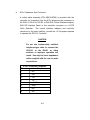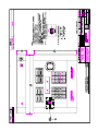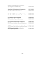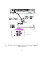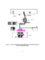
1
JPD-101
JOYSTICK
CONTROLLER
USER’S MANUAL
MANUAL NUMBER 518007-3960
Ultrak®, Inc.
4465 Coonpath Road
Carroll, OH 43112
(800) 443-6680•(740) 756-9222•FAX (740) 756-4237
Issue 1, Rev. E – January 2001
WARNING
NOT FOR OUTDOOR USE.
TO REDUCE A RISK OF FIRE OR ELECTRIC SHOCK, DO NOT
EXPOSE THIS PRODUCT TO RAIN OR MOISTURE.
WARNING
THIS IS A CLASS A PRODUCT. IN A DOMESTIC ENVIRONMENT,
THIS PRODUCT MAY CAUSE RADIO INTERFERENCE IN WHICH
CASE THE USER MAY BE REQUIRED TO TAKE ADEQUATE
MEASURES.
NOTE
This equipment generates, uses, and can radiate radio
frequency energy and if not installed and used in accordance
with the instruction manual, may cause interference to radio
communications. It has been tested and found to comply
with the limits for a Class A computing device pursuant to
subpart J of part 15 of FCC rules, which are designed to
provide reasonable protection against such interference
when operated in a commercial environment. Operation of
this equipment in a residential area is likely to cause
interference in which case the user at his own expense will
be required to take whatever measures may be required to
correct the interference.
DECLARATION OF CONFORMITY
To The European Community Council Directive 89/336/EEC
®
ISSUED BY: Ultrak , Inc.
4465 Coonpath Road NW
Carroll, OH 43112
USA
Tel: (740) 756-9222
Fax: (740) 756-4237
®
MANUFACTURER:
Ultrak , Inc.
DATE OF ISSUE:
December 22, 1995
TYPE OF EQUIPMENT:
CCTV and Security Surveillance Equipment
MODEL NUMBER:
Alarm Interface Unit
AIU-100 - may be followed by any number of alphanumeric characters.
Auxiliary Interface Units*
AIF-100/CO
Central Control Unit
CCU-100 - may be followed by any number of alphanumeric characters.
CCU-150 – may be followed by any number of alphanumeric characters.
CCU-200 – may be followed by any number of alphanumeric characters.
Joystick Multiplexer
MUX-100 – may be followed by any number of alphanumeric characters
MUX-05 – may be followed by any number of alphanumeric characters
Joystick Controller*
JPD-100, JPD-101, JPD-200 - may be followed by any number of alphanumeric
characters.
Small System Interface*
SSI-100 - may be followed by any number of alphanumeric characters.
Control Output Expander*
COE-08, COE-16 - may be followed by any number of alphanumeric characters
Control Receiver
CRX-610/BX, CRX-801AX, CRX-801BX
Control Transmitter*
UCT-10 – may be followed by any number of alphanumeric characters.
UltraKey*
KEGSA – may be followed by any number of alphanumeric characters.
*Standard EN60065 does not apply.
STANDARDS TO WHICH
CONFORMITY IS DECLARED:
EN50081-1 Emissions Standard, and EN50082-1 Immunity Standard.
EN55022 Radiated, Class A, EN55022 Conducted, Class A, IEC-1000-4-2, ESD, IEC-1000-4-3, RF Fields, IEC1000-4-4, Fast Transients/Burst.
EN60065 Safety Requirements for Mains Operated Electronic and Related Apparatus for Household and Similar
General Use
®
Ultrak , Inc. hereby declares that the models specified above conform to the directive and standard as specified.
Donald L. Stephenson
Compliance Engineer
517775-3
Rev. Q
November 9, 2000
Issue 1, Revision A – July 1997 – added caution to plug programming keyboard into
controller before power-up of system to ensure proper operation.
Issue 1, Revision B – January 1998 – updated installation drawing for JPD-101/R in
Appendix C.
Issue 1, Revision C – June 1999 – updated installation drawings in Section 4, added
lithium battery replacement and caution, added DIA-02/R installation drawing to
Appendix C.
Issue 1, Revision D – November 2000 – updated operation and programming per
firmware revision F, added Figure 4-1, Jumper Settings.
Issue 1, Revision E – January 2001 – revised the model number from KD6 EZ-Series to
KD6 Z-Series.
©1997-2000 BY ULTRAK®, INC.
ALL RIGHTS RESERVED
PRINTED IN THE UNITED STATES OF AMERICA
ULTRAK®, INCORPORATED
4465 COONPATH ROAD NW
CARROLL, OHIO 43112
(740) 756-9222
TECHNICAL SUPPORT (800) 443-6681
ALL RIGHTS RESERVED. NO PART OF THIS PUBLICATION MAY BE REPRODUCED BY ANY MEANS WITHOUT WRITTEN
PERMISSION FROM ULTRAK®, INCORPORATED.
THE INFORMATION IN THIS PUBLICATION IS BELIEVED TO BE ACCURATE IN ALL RESPECTS. HOWEVER, ULTRAK®,
INCORPORATED CANNOT ASSUME RESPONSIBILITY FOR ANY CONSEQUENCES RESULTING FROM THE USE THEREOF.
THE INFORMATION CONTAINED HEREIN IS SUBJECT TO CHANGE WITHOUT NOTICE. REVISIONS OR NEW EDITIONS TO
THIS PUBLICATION MAY BE ISSUED TO INCORPORATE SUCH CHANGES.
TERMS
The following terms are used often throughout this manual. Please become familiar
with them before operating and programming a SmartScan system. Refer to the
specific SmartScan, SmartScan Pro, SmartScan Pro II, or SmartScan III Operation and
Programming Manual for SmartScan programming procedures. The term SmartScan is
used generically for all models unless a term applies to a specific model.
PreShot
A PreShot is a camera/lens position including, pan, tilt, zoom, and focus that can be
given a title and stored in a SmartScan unit. Up to 100 PreShots can be programmed
and stored in each SmartScan unit. PreShots are programmed using a KBD-100
Programming Keyboard and a JPD-101Controller. “Quick” PreShots can be
programmed using the JPD-101 Controller alone. See Section 3 of this manual for
programming “Quick” PreShots.
An operator can send a SmartScan unit to a programmed PreShot using the JPD-101
Controller. When the SmartScan unit is sent to a PreShot, the title of the PreShot is
added to the video signal.
VectorScan
A VectorScan can be considered a video tour. It is two or more PreShots (from the
same SmartScan unit) linked together with dwell times between each PreShot. Up to
ten VectorScans can be programmed and stored in each SmartScan unit. VectorScans
are programmed using the KBD-100 Keyboard and the JPD-101 Controller.
They can be started/stopped at the Controller. When a VectorScan is running in a
SmartScan unit, the title of the PreShot currently being viewed is added to the
SmartScan video signal.
Sector ID
Sector IDs are used for labeling defined areas the SmartScan unit views. Up to 16
Sector IDs can be programmed and stored in each SmartScan unit. Sector ID's are
programmed using a KBD-100 Programming Keyboard and JPD-101 Controller.
Whenever the SmartScan unit is under manual control and viewing a programmed
Sector, the title of the Sector is added to the SmartScan video signal. Note: The
camera ID display must be enabled; if the camera ID display is disabled, the Sector title
is also disabled.
TABLE OF CONTENTS
Page
SECTION 1. INTRODUCTION ....................................................................................1-1
1.1 DESCRIPTION ..................................................................................................1-1
1.2 OPERATION......................................................................................................1-1
1.3 INSTALLATION .................................................................................................1-3
1.4 SPECIFICATIONS.............................................................................................1-5
SECTION 2. OPERATION ..........................................................................................2-1
2.1 CONTROLS AND INDICATORS .......................................................................2-1
2.1.1
Top Panel Controls and Indicators. .........................................................2-1
2.1.2
Rear Panel Controls and Indicators. .....................................................2-10
2.2 OPERATION....................................................................................................2-11
2.2.1
LCD Display Language Selection .........................................................2-13
2.2.2
Setting the Address in the ValuDome ...................................................2-14
2.2.3
Primary Control Camera and Control Monitor. ......................................2-15
2.2.4
Secondary Control Camera And Monitor. .............................................2-20
2.2.5
Switch Secondary Control To Primary Control. .....................................2-24
2.2.6
Call Up Any Camera To Any Monitor. ...................................................2-25
2.2.7
PreShots ...............................................................................................2-27
2.2.7.1 List Programmed PreShots (not applicable to ValuDome) ................2-27
2.2.7.2 Go To PreShot...................................................................................2-28
2.2.8
VectorScans..........................................................................................2-31
2.2.8.1 Programming VectorScans in the ValuDome. ...................................2-31
2.2.8.2 List VectorScans (Not applicable to ValuDome) ................................2-33
2.2.8.3 List VectorScan Contents (Not applicable to ValuDome) ..................2-34
2.2.8.4 Run VectorScan ................................................................................2-35
2.2.8.5 Stop VectorScan................................................................................2-37
2.2.9
Sector ID List (not applicable to ValuDome) .........................................2-38
i
TABLE OF CONTENTS
Page
2.2.10
Monitor Sequencing (1-32)....................................................................2-39
2.2.11
Auxiliary Contact Output Control (ON/OFF) ..........................................2-42
2.2.12
Manual Control of SmartScan. ..............................................................2-46
2.2.13
Find Home. ...........................................................................................2-47
2.2.14
Freeze or Unfreeze Video (KD6 UltraDome only) .................................2-48
2.2.15
Tours (KD6 UltraDome only) .................................................................2-49
2.2.15.1 Programming Tours...........................................................................2-49
2.2.15.2 Run Tour ...........................................................................................2-50
2.2.15.3 Stop Tour...........................................................................................2-51
2.2.16
Joystick Diagnostics..............................................................................2-52
2.2.17
Camera ID Display on Monitor. .............................................................2-54
2.2.18
Pan, Tilt, Zoom, and Focus Azimuth Display/Error Log Display. ...........2-56
SECTION 3. PROGRAMMING....................................................................................3-1
3.1 PRESHOTS .......................................................................................................3-1
3.2 PROGRAMMING THE EIGHT FUNCTION KEYS ON THE JPD-101
CONTROLLER .........................................................................................................3-3
3.2.1
Programming a Function Key..................................................................3-4
3.2.2
Modify an Action Programmed for a Function Key. ...............................3-11
3.2.3
Inserting An Action Between Actions For A Function Key.....................3-13
3.2.4
Deleting An Action For A Function Key. ................................................3-13
3.2.5
Clearing a Function Key........................................................................3-14
3.2.6
Exit the Function Key Programming Mode............................................3-14
3.3 PROGRAMMING MONITOR SEQUENCES IN THE CATS VIDEO
SWITCHER......................................................................................................3-15
SECTION 4. SETUP AND INSTALLATION................................................................4-1
4.1 SETUP PROCEDURES.....................................................................................4-1
4.1.1
Master/Slave. ..........................................................................................4-2
ii
TABLE OF CONTENTS
Page
4.1.2
Enable/Disable Communications. ...........................................................4-3
4.2 INTERCONNECTING CABLING REQUIREMENTS AND CONNECTOR
PIN-OUT ASSIGNMENTS .................................................................................4-3
4.3 EQUIPMENT INTERCONNECTIONS ...............................................................4-5
4.3.1
Stand-Alone Controller Installation..........................................................4-6
4.3.2
One Controller And CATS Video Switcher Installation. ...........................4-8
4.3.2.1 JPD-101 Connected to Front Panel of CATS Video Switcher. ............4-8
4.3.2.2 JPD-101 Connected to Rear Panel of CATS Video Switcher. ...........4-10
4.3.3
Two Controllers Linked Together Installation. .......................................4-12
4.3.4
Two Controllers Linked Together And A CATS Video Switcher
Installation.............................................................................................4-14
4.3.4.1 Two Controllers Connected to CATS Video Switcher Front Panel
Input. .................................................................................................4-14
4.3.4.2 Two Controllers Connected to CATS Video Switcher Rear Panel
Input. .................................................................................................4-17
4.4 INSTALLATION DRAWINGS...........................................................................4-19
SECTION 5. MAINTENANCE .....................................................................................5-1
5.1 MAINTENANCE PROCEDURES ......................................................................5-1
5.2 RETURNING EQUIPMENT TO ULTRAK ..........................................................5-3
APPENDIX A. REFERENCE MATERIALS................................................................ A-1
A.1 USER'S MANUAL INDEX................................................................................. A-1
APPENDIX B. QUICK REFERENCE GUIDE............................................................. B-1
APPENDIX C. INSTALLATION JPD-101/R RACK MOUNT JOYSTICK
CONTROLLER ................................................................................... C-1
C.1 DESCRIPTION ................................................................................................. C-1
C.2 INSTALLATION ................................................................................................ C-1
C.2.1
Stand-Alone Controller........................................................................... C-2
C.2.2
CATS Video Switcher............................................................................. C-4
iii
TABLE OF CONTENTS
Page
C.2.2.1 CATS Video Switcher Rear Panel Installation .................................... C-4
C.2.2.2 CATS Video Switcher Front Panel Installation ................................... C-6
C.3 INSTALLATION DRAWING .............................................................................. C-8
LIST OF FIGURES
Page
Figure 2-1. CONTROLS AND INDICATORS, TOP PANEL.........................................2-1
Figure 2-2. CONTROLS AND INDICATORS, REAR PANEL ....................................2-10
Figure 4-1. JUMPER SETTINGS.................................................................................4-2
Figure 4-2. JPD-101 CONTROLLER AS A STAND-ALONE UNIT ..............................4-7
Figure 4-3. TYPICAL INTERCONNECT WITH JPD-101 SMART HAND
CONTROLLER AND CATS VIDEO SWITCHER .......................................4-9
Figure 4-4. JPD-101 CONTROLLER W/CATS VIDEO SWITCHER (REAR
PANEL CONNECTOR)............................................................................4-11
Figure 4-5. TWO JPD-101 CONTROLLERS LINKED TOGETHER ..........................4-13
Figure 4-6. TWO CONTROLLERS LINKED TOGETHER W/CATS VIDEO
SWITCHER (FRONT PANEL CONNECTOR) .........................................4-15
Figure 4-7. TWO CONTROLLERS LINKED TOGETHER W/CATS VIDEO
SWITCHER (REAR COMM CONNECTOR) ............................................4-18
Figure C-1. JPD-101/R AS A STAND-ALONE CONTROLLER .................................. C-3
Figure C-2. JPD-101/R CONNECTED TO THE COMM CONNECTOR OF THE
CATS VIDEO SWITCHER ........................................................................ C-5
Figure C-3. JPD-101/R CONTROLLER CONNECTED TO THE FRONT PANEL
ON THE CATS VIDEO SWITCHER ........................................................ C-7
iv
LIST OF TABLES
Page
Table 2-1. CONTROL COMMANDS..........................................................................2-58
Table 4-1. MASTER/SLAVE CONFIGURATION .........................................................4-3
Table 4-2. ENABLE/DISABLE COMMUNICATIONS...................................................4-3
LIST OF DRAWINGS
Page
JPD-101 Controller Unit Installation (D/N 517057-2430) ............................................4-20
DIA-01 Control Interface Adapter (D/N 515558-2430)................................................4-21
DIA-01/X Control Interface Adapter (D/N 515558-4430) ............................................4-22
DIA-02 Control Interface Adapter (D/N 517172-1430)................................................4-23
DIA-02/X Control Interface Adapter (D/N 517172-3430) ............................................4-24
JPD-101/R Joystick Controller Unit Installation (D/N 700385-1430)........................... C-9
DIA-01/R Control Interface Panel Rack Mount (D/N 515979-1430)........................... C-10
DIA-02/R Control Interface Panel Rack Mount (D/N 515979-2430).......................... C-11
v
This page left blank intentionally.
vi
SECTION 1. INTRODUCTION
1.1
DESCRIPTION
The JPD-101 Joystick Controller is an operator interface device designed to
remotely control FastScan pan and tilt units, SmartScan pan and tilt units, and
CAT video switchers. There are various models of FastScan and SmartScan
pan and tilt units. The features vary between models. The JPD-101 Controller is
designed to control the many different features of all the models. The JPD-101
may have a feature that is not supported by your model pan and tilt unit. Refer to
your specific pan and tilt unit’s operation and programming manual for the
available features.
The JPD-101 Controller has one 3-axis proportional joystick for pan, tilt, and
zoom control and one 2-axis joystick for lens iris and focus control. It has two 12key keypads for data entry and system control. Each controller has eight
function keys across the top of the controller that can be programmed to perform
one or more system functions (up to 8) with a single keystroke.
An LCD Display in the center of the controller shows the control camera and
monitor, operator entered keystrokes and system messages and prompts. The
language for the LCD display is selectable between English, French, German, or
Spanish.
An operator can program “Quick” PreShots using the JPD-101 Controller. Refer
to Section 3 of this manual for the procedure to program “Quick” PreShots.
1.2
OPERATION
The JPD-101 Controllers send out RS-485 operator entered control data at 9600
baud to perform the following system functions.
1-1
• Manual Control (pan, tilt, zoom, focus, and iris) of FastScan or SmartScan
•
•
•
•
•
•
•
•
•
•
•
domes. Lens iris manual control requires MIO-100 auto iris override option in
standard FastScan or SmartScan.
Perform video switching: 250 cameras to 32 monitors
Program “Quick” PreShots in SmartScan domes
Execute PreShots
Program VectorScans (1-3) in the KD6 Z-Series
Start/stop VectorScans
List programmed PreShots, VectorScans, VectorScan contents, and Sector
ID's stored in SmartScan units (not available in KD6 Z-Series)
Control auxiliary devices
Monitor Sequence Control (sequences stored in CATS video switcher)
Set the address of the KD6 Z-Series
Program Tours and Run Tours in the KD6 UltraDome
Freeze and unfreeze the video scene in the KD6 UltraDome.
The JPD-101 Controllers allow the operator to have a primary control camera
and monitor and a secondary control camera and monitor. If a secondary
camera and monitor is selected, all manual control (pan, tilt, zoom, focus, and
iris), auxiliary control, and programming procedures are sent to the primary
control camera and viewed on the primary control monitor. All automatic control
(PreShots, VectorScans) is sent to the secondary control camera. The
secondary control camera must be switched to the secondary control monitor to
view the video on the secondary control monitor.
The KBD-100A keyboard interface allows the operator to program PreShots,
VectorScans, and Sector ID’s if supported by the pan and tilt unit. The KBD100A keyboard can also be used to send SmartScan units to PreShots, run
VectorScans once or continuously, list programmed PreShots, VectorScans,
VectorScan contents, and Sector IDs, and find home (initialize the dome
position). Refer to your specific SmartScan (SmartScan, SmartScan Pro II,
SmartScan III, KD6 Ultradome, and KD6 Z-Series) Operation and Programming
Manual for available features and programming procedures.
1-2
The JPD-101 Controllers have eight programmable function (quick keys). The
function keys are programmed using the two 12-key keypads and the small
joystick on the controller. The function keys are designed to perform a single
action or up to eight actions simultaneously or in a series with programmable
dwell times between actions using a single keystroke. These actions include all
the functions of a SmartScan system such as PreShots, VectorScans, video
switching, and auxiliary control (VCRs), etc. A dwell time (wait) of 00-99 seconds
can be programmed as an action between actions. Functions keys 5-7 can be
set to run tours 1 – 3 stored in a KD6 UltraDome. Function key 8 can be set to
enable or disable the freeze frame feature of the KD6 UltraDome. Refer to
Section 3 of this manual for programming the eight function keys. Refer to
Section 2 of this manual for setting the function keys to start tours and control the
freeze frame feature in the KD6 UltraDome.
1.3
INSTALLATION
There are four standard installations for the JPD-101 Controllers.
1.
Stand-Alone Controller
When the JPD-101 Controller is used as a stand-alone controller, a DIA01 or DIA-01/X Control Interface is required. The Control Interface
Adapter provides the +5 Vdc power required to operate the JPD-101
Controller. The DIA-01 has a 120 Vac to 5 Vdc power supply. The DIA01/X has a 220 Vac to 5 Vdc power supply. These control interface
adapters also provide the control data wiring block for connection to the
FastScan/ SmartScan domes.
1-3
2.
JPD-101 with a CATS Video Switcher
When the JPD-101 Controller is installed with a CATS Video Switcher, the
controller can be plugged into the front panel controller connector on the
CATS Video Switcher. The front panel controller connector provides the
+5 Vdc required for the controller.
If the JPD-101 Controller needs to be installed remotely from the CATS
Video Switcher, the rear panel COMM input port can be used. The rear
panel input port does not provide the +5 Vdc required by the controller so
a DIA-01 or DIA-01/X Control Interface Adapter is required between the
controller and the switcher. The DIA-01 provides a 120 Vac ±10% to
+5Vdc power supply. The DIA-01/X provides a 220 Vac ±10% to +5Vdc
power supply. The maximum distance between the control interface
adapter and the video switcher is 4000 feet (1219 meters).
3.
Two JPD-101 Controllers linked together for two control locations
Two controllers can be linked together using two DIA-02 (120Vac±10% to
+5Vdc) or two DIA-02/X (220Vac±10% to +5Vdc) Control Interface
Adapters. One of the controllers is configured as the master unit and the
other is configured as the slave unit. Both units function as stand-alone
controllers. The only difference is the way they are installed in the system
and their communication path. The control data from the slave controller
is sent through the master controller.
1-4
4.
Two JPD-101 Controllers linked together with a CATS Video Switcher
Two JPD-101 Controllers can be linked together using two DIA-02 Control
Interface Adapters and then connected to a CATS Video Switcher. One of
the controllers is configured as the master unit and the other is configured
as the slave unit. Both units function as stand-alone controllers. If
connecting to the front panel controller connector on the CATS switcher,
an additional coiled cable (P/N 849518-0306) is required.
1.4
SPECIFICATIONS
Power Requirements:
Voltage Requirements:
Communication:
Baud Rate:
Dimensions:
Weight:
Operating Temperature:
Humidity:
300ma Max.
+5 Vdc ±5%
RS-485 Twisted-Pair
9600 Baud
11.81” W x 1.88” H x 8.88” D
(2999.9 mm W x 47.8 mm H x 225.6 mm D)
Approximately 3 lb. (1.4 kg)
+32°F (0°C) to 120°F (+50°C)
0 to 95% relative, non-condensing
1-5
This page left blank intentionally.
1-6
SECTION 2. OPERATION
2.1
2.1.1
CONTROLS AND INDICATORS
Top Panel Controls and Indicators.
Figure 2-1. CONTROLS AND INDICATORS, TOP PANEL
2-1
LARGE JOYSTICK OPERATION
1
LARGE JOYSTICK
The large joystick controls the pan, tilt, and zoom functions of a
Fastscan/Smartscan unit. The joystick control is rate proportional; the farther the
joystick is moved, the faster the function is performed.
The large joystick is also used to halt VectorScans and Tours in a SmartScan
unit and return the SmartScan to manual control. The SmartScan unit where the
VectorScan or Tour is running must be the primary control camera. Move the
joystick in any direction while a VectorScan or Tour is running to stop the
VectorScan or Tour.
Auto Pivot Function
If the auto pivot function is enabled in the pan and tilt unit, the pan and tilt rotates
180° when the camera reaches vertical. This function assists operators in
tracking an individual that moves directly under the camera. When the camera is
in the vertical position, push the large joystick down and hold it down until the
pan and tilt rotates 180°; continue holding the joystick down and the unit tilts up
as long as the joystick remains in the “down” position. When the joystick is
returned to its neutral position, operation returns to normal. Refer to your specific
pan and tilt unit’s user’s manual for availability of this feature in your unit.
2-2
SMALL JOYSTICK OPERATION
PASS Function
If the PASS function is enabled in the SmartScan unit, the pan and tilt speed
range is a function of the lens zoom angle. As the lens is zoomed in, the
maximum pan and tilt speeds are reduced and the low speed control is
expanded. Refer to your specific pan and tilt unit’s user’s manual for availability
of this feature in your unit.
2
SMALL JOYSTICK
MANUAL CONTROL MODE
The focus functions are operational upon power-up of the unit. The iris function
is set to automatic upon power-up of the unit. To manually control the iris, the
MIO-100 Option must be installed on the FastScan or SmartScan unit. The
FastScan Pro II, SmartScan Pro II, KD6 UltraDome and KD6 Z-Series units have
manual and automatic iris control; an option is not required.
2-3
SMALL JOYSTICK OPERATION
MANUAL IRIS CONTROL
STEP 1
Press the IRIS key on the function keypad and then the 2 key on the numeric
keypad.
IRIS
2
When manual iris is selected for the control camera, the letter I appears on
the second line of the LCD display.
I
CNTL - CAM 1 MON 1
NOTE
When the operator changes the control
camera, the iris function stays in the manual
mode.
2-4
SMALL JOYSTICK OPERATION
AUTOMATIC IRIS
The operator can change back to automatic iris anytime while controlling
the camera.
STEP 1
Press the IRIS key on the function keypad and then the 1 key on the
numeric keypad.
IRIS
1
When automatic iris is selected, the letter I disappears from the second
line of the LCD display.
CNTL - CAM 1 MON 1
2-5
SMALL JOYSTICK OPERATION
PROGRAMMING MODE
When the function key programming mode (PRGM>1) is accessed, the small
joystick becomes a programming tool. Movement of the joystick right moves the
cursor to the next menu option and left moves the cursor to the previous menu
option. Movement of the joystick up and down activates the menu option
highlighted by the cursor. When programming the specific actions for the
function keys, moving the joystick up and down can also be used to scroll
through the actions (one through eight). When the JPD-101 is in the function key
programming mode, the lens focus and iris functions are not operational.
2-6
LCD DISPLAY
NUMERIC KEYPAD
3
LCD DISPLAY
The display is a 2X20 EL back light super twist LCD. The viewing angle of the
display may be changed by turning the screwdriver adjustment on the back panel
(see figure 2-2). The first line of the display indicates the primary monitor
(number) and camera (number) the hand controller unit is controlling. The
second line indicates the secondary camera (number) and monitor (number), if
one is selected.
The second line of the display shows each keystroke as it is entered. Any input
errors may be corrected by pressing the CLEAR key and re-entering the data.
All messages and prompts are also displayed on the second line. The display
blinks at various data entry points to indicate more data needs to be entered or a
key pressed to complete a command. The controller returns to the secondary
camera/monitor when done displaying messages or prompts.
The language is selectable (English, Spanish, German, and French) for
displaying the messages and prompts on the LCD display.
4
NUMERIC KEYPAD
The numeric keypad is used to enter camera numbers, monitor numbers,
PreShot numbers, VectorScan numbers, etc. The CLEAR key is used to clear
data entries or the second camera and monitor. The ENTER key is used to
complete a data or function entry.
2-7
FUNCTION KEYPAD
5
FUNCTION KEYPAD
The function keypad is used in conjunction with the numeric keypad to carry out
the control functions of the FastScan and SmartScan assemblies and CATS
Video Switcher.
- Camera/Monitor Switching (CAM, MON, ENTER, CNTL) - up to 250 cameras
to 32 monitors
- Manual/Auto Iris Control (IRIS) - if MIO-100 option is installed in FastScan or
SmartScan receiver unit. Manual/auto iris always available in SmartScan Pro
II, SmartScan III, KD6 UltraDome and KD6 Z-Series Dome units.
- Auxiliary Output Control (AUX) - if used with CATS video switcher, AIF100/CO, CRX-800 or CRX-801 Control Receivers, or CRX-500 Series Control
Receivers
- Program “Quick” PreShots
- PreShot Call-up (PSHOT)
- PreShot Listing (OPT)
- Run VectorScan (VSCAN)
- Program VectorScans 1-3 in the KD6 Z-Series Dome
- VectorScan Listing (OPT)
- Sector Listing (OPT)
- Controller Diagnostics (OPT)
- SmartScan Functions (OPT) - find home, manual control
- Enable/Disable Camera ID Display, Coordinate Display or Error Log Display
(OPT)
- CATS Monitor Sequence Control (SEQ)
- Select LCD Display Language (OPT)
- Set KD6 Z-Series Dome Address (OPT)
- Program and Run Tours (OPT)
- Freeze and Unfreeze video in the KD6 Dome (OPT)
The MCALL and ALARM keys are not functional on the JPD-101 Controllers.
2-8
FUNCTION KEYS 1-8
6
FUNCTION KEYS 1-8
Function keys 1 through 8 are programmable using the two 12-key keypads and
the small joystick. These keys can be programmed to perform a single action or
up to eight actions simultaneously. If the operator does not want the actions to
occur simultaneously, a delay time (wait) can be inserted as an action between
actions. The actions that can be programmed are PreShots, VectorScans, video
switching, and auxiliary control (video recording).
Pressing the function key starts the action(s) programmed. Pressing the key
again stops the action(s). If the key is not programmed, nothing happens when
the key is pressed.
NOTE
If a VectorScan is started when a function key
is pressed, the VectorScan continues to run
until manual control of the camera, where the
VectorScan is running, is taken. Pressing the
function key does not halt a VectorScan.
Function keys 5, 6, and 7 can also be set to run tours 1, 2, and 3, respectively.
Function key 8 can also be set to enable and disable the freeze frame feature in
the KD6 UltraDome. Refer to paragraphs 2.2.14 and 2.2.15.
2-9
2.1.2
Rear Panel Controls and Indicators.
Figure 2-2. CONTROLS AND INDICATORS, REAR PANEL
7
VIEWING ANGLE ADJUSTMENT
This screwdriver adjustment is used to change the viewing angle of the LCD
Display.
8
8-PIN TELEPHONE JACK CONNECTOR
This connector accepts +5 Vdc power for the Joystick Controller and
inputs/outputs RS-422 control data. A coiled cable assembly (P/N 849518-0306)
is provided with the unit for connection to the various equipment types.
9
5-PIN DIN CONNECTOR
This connector is used for connection to the KBD-100A keyboard interface. The
KBD-100 Keyboard is required to program PreShots, VectorScans, and Sector
ID's in SmartScan units.
2-10
2.2
OPERATION
CAUTION
Before Powering-Up The System, Make
Sure
The
Programming
Keyboard
Is
Plugged Into The JPD-101 Controller. If The
Keyboard Is Plugged In After Power-Up,
Improper Operation May Occur.
Operation can begin when power is applied to all components in the system.
Upon power-up of a JPD-101 Controller, the LCD display shows the control
camera and control monitor. The control camera and control monitor displayed
upon power up depends on the configuration of the controller. Refer to Section 4
for configuring the controller.
Master Unit with Receive Communications Enabled:
CNTL - CAM 1 MON 1
Master Unit with Receive Communications Disabled:
CNTL - CAM 2 MON 1
Slave Unit with Receive Communications Enabled:
CNTL - CAM 2 MON 2
All operator control data (pan, tilt, zoom, focus, iris, PreShots, VectorScans, etc.)
is sent to the control camera.
2-11
Operation of a master unit and a slave unit are exactly the same. The only
difference is the communication path. The slave controller sends its control data
to the master controller. The master controller sends it control data and the slave
unit’s control data to the DIA-02 Control Interface Adapter and then to the domes
or video switcher.
When two JPD-101 Controllers are linked together and communication is
enabled, the LCD display updates when both controllers have the same control
monitor and one of the operators changes the control camera. For example, the
master controller has control monitor 1 and control camera 3, and the slave
controller has control monitor 1 and control camera 3. If the operator at one of
the controllers changes to control camera 1, the display on the other controller
changes to control camera 1 because they have the same control monitor.
If both controllers have the same control camera displayed, whichever controller
requested control last has manual control of the camera. If an operator does not
have manual control of the control camera shown on the LCD display, pressing
the CNTL key on the controller gets control.
A secondary control camera/monitor has to be selected by an operator. A video
switcher is usually installed in a system with more than one camera and/or
monitor. If a secondary control camera is selected, all manual control data (pan,
tilt, zoom, focus, and iris) is sent to the primary control camera and all PreShot
and VectorScan control data is sent to the secondary control camera.
NOTE
If power is interrupted to the system,
unplug the controller for 5 seconds and
then plug it back in. If this procedure is not
done, incorrect operation may occur.
2-12
LCD LANGUAGE
2.2.1
LCD Display Language Selection
Upon power-up of the controller, the second line of the LCD display shows
the firmware and revision, then:
CNTL – CAM 1
MON 1
OPT>1 >1 CHANGE LANG
The LCD displays can be presented in English, French, German, and
Spanish.
To select the language used for the LCD display,
Press OPT to view the LCD menu options
OPT
Press 1 (MISC)
1
Press 1 (LANGUAGE)
1
Press 1 for English,
1
Press 2 for Spanish,
2
Press 3 for German, or
3
Press 4 for French.
4
The LCD menus, messages, and prompts are displayed in the language
selected.
2-13
SET ADDRESS IN KD6 Z-SERIES
2.2.2
Setting the Address in the KD6 Z-Series Dome
To set the address of a KD6 Z-Series Dome, you must know the serial
number. The serial number is eight (8) digits and can be located on the KD6
Z-Series Dome pan and tilt unit. Note: all other dome addresses are set
using rotary switches or a DIP switch on the receiver board.
Press OPT to view the LCD menu options
OPT
Press 1 (MISC)
1
Press 2 (SET ADD) to set the address
2
Enter the Serial Number (8 digits)
of the KD6 Z-Series (SN-). Enter the leading
character A of the serial number as a 0.
Press Enter.
SN#
Enter
Enter the desired address of the dome (1-250)
Press Enter
###
Enter
The LCD displays the message, “Updating Address”.
The address is the camera number the operator uses to call-up and control
the dome.
2-14
PRIMARY CONTROL CAMERA
2.2.3
Primary Control Camera and Control Monitor.
Upon power-up of the system, the primary control camera and monitor are
camera one and monitor one.
A secondary control camera/monitor
combination, if desired, has to be selected.
The first line of the display on the controller shows the CAM and the MON
the controller is controlling. On the controller, the camera number has a
symbol that looks like a camera beside it and the monitor number has a
symbol that looks like a monitor beside it.
CNTL - CAM 1
MON 1
Use the following command sequences to change the primary camera/monitor combination currently under control of the Joystick Controller.
CHANGE PRIMARY CONTROL CAMERA
To change the control camera (but not the control monitor), enter one of
the following command sequences.
NOTE
The commands are in bold typeface and are
separated by the symbol >.
2-15
PRIMARY CONTROL CAMERA
Camera #>ENTER
#
ENTER
#
CNTL
or
Camera#>CNTL
The controller sends a command to the switcher to switch the selected
camera to the monitor currently displayed on the controller.
NOTE
If a camera number is displayed on the first line
of the JPD display, but the operator cannot
manually control that camera, press the CNTL
key to get manual control. The controller loses
manual control when another operator
requests control.
2-16
PRIMARY CONTROL CAMERA
Example:
The display on the controller shows CAM 1 and MON 1.
CNTL - CAM 1
MON 1
Enter the following command sequence to change the control camera to 5.
5>ENTER
or
5>CNTL
Now, the controller display shows CAM 5/MON1.
CNTL - CAM 5
MON 1
All control commands are sent to camera 5 and the video from camera 5
is viewed on monitor 1.
2-17
PRIMARY CONTROL MONITOR
CHANGE PRIMARY CONTROL MONITOR
To change the control monitor (but not the control camera), enter the one of
the following command sequences.
a. Monitor #>MON>ENTER
#
MON
ENTER
#
MON
CNTL
or
b. Monitor #>MON>CNTL
or
c. Press MON.
The following message appears on the controller LCD display.
CNTL - CAM 1
Enter MON. NO.
MON 1
Type in the monitor number (1-32) using the numeric keypad.
Press ENTER twice or press ENTER CNTL.
MON
#
ENTER
ENTER
MON
#
ENTER
CNTL
or
2-18
PRIMARY CONTROL MONITOR
Example:
The display on the controller shows CAM 1/MON 1.
CNTL - CAM 1
MON 1
Enter the following command sequence to change the control monitor to 3.
3>MON>ENTER
or
3>MON>CNTL
or
MON>3>ENTER>ENTER
or
MON>3>ENTER>CNTL
Now the display shows CAM 1/MON 3.
CNTL - CAM 1
MON 3
All control commands are performed on camera 1 and the video from
camera 1 is viewed on monitor 3.
2-19
SECONDARY CONTROL CAMERA
2.2.4
Secondary Control Camera And Monitor.
The secondary camera and monitor are displayed on the second line of the
display. The camera number can be entered first and the monitor number
second or vice versa.
If the monitor number is entered first, it appears on the second line. When
the camera number is entered, the controller places the camera number in
front of the monitor number.
SELECTING A SECONDARY CAMERA
To select a secondary camera, enter one of the following command sequences.
Camera #>CAM
#
CAM
or
CAM>Camera #>ENTER
CAM
#
ENTER
The camera number selected appears on the second line of the
controller's LCD display. All automatic commands (PreShot, VectorScan)
are sent to the secondary camera.
2-20
SECONDARY CONTROL CAMERA
Example:
Select camera 2 as the secondary camera.
2>CAM
The number 2 shows up on the second line of the controller display.
CNTL - CAM 1
2
MON 1
All automatic commands (PreShots, VectorScans) are sent to camera
2.
2-21
SECONDARY CONTROL MONITOR
SELECTING A SECONDARY MONITOR
To select a secondary monitor, enter one of the following command sequences.
Monitor #>MON
#
MON
MON
#
or
MON>Monitor #>ENTER
ENTER
The secondary monitor appears on the second line of the controller
display.
Example:
Select monitor 2 as the secondary monitor.
2>MON
or
MON >2>ENTER
Monitor 2 appears on the second line of the controller display.
CNTL - CAM 1 MON 1
22
2-22
SECONDARY CAMERA/MONITOR
CALL UP SECONDARY CAMERA TO SECONDARY MONITOR
To switch the video of the secondary camera to the secondary monitor,
secondary camera and monitor must be selected first and displayed on
second line of the controller LCD display. Press the ENTER key on
controller. The controller sends out a command to the switcher to switch
secondary camera to the secondary monitor.
the
the
the
the
The following message is briefly displayed after pressing ENTER.
CNTL - CAM 1
Call CAM# MON#
MON 1
CLEAR SECONDARY CAMERA/MONITOR
Press the CLEAR key on the numeric keypad until the second line is clear.
2-23
SECONDARY CONTROL TO PRIMARY CONTROL
2.2.5
Switch Secondary Control To Primary Control.
To have the secondary camera/monitor combination displayed become the
primary camera/monitor combination, press CNTL. The camera/monitor
combination on the second line of the LCD display moves to the first line of
the display. The second line of the display is empty.
Example:
CAM 1/MON 1 is the primary control camera/monitor combination and CAM
2/MON 2 is the secondary camera/monitor combination.
CNTL - CAM 1
2 2
MON 1
Press CNTL.
CAM 2 and MON 2 become the primary control camera/monitor combination and the second line disappears.
CNTL - CAM 2
MON 2
2-24
VIDEO SWITCHING
2.2.6
Call Up Any Camera To Any Monitor.
To call up any camera to any monitor without giving up PreShot and
VectorScan control of the primary camera, perform the procedures for calling
up a secondary camera to a secondary monitor. Then clear them from the
display on the controller by pressing the CLEAR key until the second line of
the display is empty. The video from the secondary camera remains on the
secondary monitor until the switcher receives a switching command involving
either the camera or monitor.
#
CAM
#
MON
Example:
Call up Camera 2 to Monitor 2.
Present LCD Display:
CNTL - CAM 1
MON 1
2>CAM
CNTL - CAM 1
2
MON 1
2-25
ENTER
CLEAR
CLEAR
VIDEO SWITCHING
2>MON
CNTL - CAM 1
2 2
MON 1
ENTER
The controller sends out a command to switch camera 2 to monitor 2.
CLEAR
CNTL - CAM 1
2
MON 1
CLEAR
CNTL - CAM 1
MON 1
Camera 2 remains on monitor 2 until the operator calls up another camera to
monitor 2.
2-26
PRESHOTS
2.2.7
PreShots
Each SmartScan unit can store up to 100 PreShots (00-99). The KD6 ZSeries can store up to 64 PreShots (1-64). A list of the programmed
PreShots for each SmartScan unit can be called up using the controller for
display on a monitor. The operator can send the control camera (or
secondary camera, if selected) to any of its programmed PreShots using the
controller. Refer to Section 3 of this manual for programming a “Quick
PreShot. Refer to the specific SmartScan (SmartScan, SmartScan Pro,
SmartScan Pro II, SmartScan III series, or KD6 UltraDome) Operating and
Programming Manual for complete programming procedures.
2.2.7.1
List Programmed PreShots (not applicable to KD6 Z-Series)
The list displays the PreShot numbers and their titles. The listing cannot
be edited. Perform the following command sequence to view the list of
PreShots for the primary (or secondary, if selected) control camera.
Follow the prompts on the controller display.
Press OPT
OPT
Press 5 on the numeric keypad (listings)
5
Press 1 on the numeric keypad (PreShots)
1
Press 1 to view the next page of the list.
1
Press 2 when done viewing the list.
2
2-27
PRESHOTS
2.2.7.2
Go To PreShot
A PreShot call is sent to the control camera unless a secondary control
camera is selected, then it is sent to the secondary camera. To view the
PreShot scene, the camera must be called up on a monitor.
There are two command sequences to go to a PreShot.
1.
Enter the PreShot # and Press PSHOT
#
PSHOT
or
2.
Press PSHOT
The controller displays the following message:
CNTL - CAM 1
MON 1
Enter Shot No._
Enter the Preshot#
Press ENTER
PSHOT
#
ENTER
The controller sends out a command for camera one to go to the specified PreShot. The PreShot scene can be viewed on the monitor the
SmartScan unit is called up on. The title of the PreShot is displayed on
the monitor. If the PreShot does not exist, the SmartScan outputs the
message 'DOES NOT EXIST' on the video signal.
2-28
PRESHOTS
Example:
The controller display shows:
CNTL - CAM 1
MON 1
(no secondary camera/monitor selected)
Send camera one to PreShot 2. Enter one of the two following command
sequences.
1.
2>PSHOT
or
2.
PSHOT>2>ENTER
SmartScan unit one (camera 1) goes to PreShot position 2. The video
from PreShot 2 and the title of PreShot 2 are viewed on monitor 1. If the
camera ID is enabled in the SmartScan unit, the camera number
appears on the bottom of the monitor with the letter A beside it for
automatic operation.
PreShot Title
CAM 001 A
2-29
PRESHOTS
Note: on some pan and tilt models, the PreShot title and camera ID
display positions are programmable. They may not be located in the
positions shown. The KD6 Z-Series does not display any on-screen
messages.
2-30
VECTORSCANS
2.2.8
VectorScans.
Each SmartScan, SmartScan Pro II, SmartScan III series, or KD6 unit can
store up to 10 VectorScans (0-9). A list of the programmed VectorScans for
each unit can be called up for display on a monitor using the controller. The
contents of each VectorScan can be called up for display on a monitor using
the controller. Each KD6 Z-Series can store up to 3 VectorScans (1-3). The
operator can start any of the programmed VectorScans on the control
camera (or secondary camera, if selected) using the controller. Refer to the
specific SmartScan (SmartScan, SmartScan Pro, SmartScan Pro II,
SmartScan III, KD6 UltraDome, or KD6 Z-Series) Operating and
Programming Manual for programming procedures.
2.2.8.1
Programming VectorScans in the KD6 Z-Series.
Three VectorScans can be stored in the KD6 Z-Series. Each
VectorScan can be programmed with up to 16 PreShots with a dwell time
(0-30 seconds) between each PreShot. Perform the following procedure
to program and store a VectorScan in a KD6 Z-Series.
Press the OPT key.
OPT
Press 4 (PROG)
4
Press 2 (VectorScan)
2
Enter the VectorScan # (1-3)
Press Enter
VS#
Enter
2-31
VECTORSCANS
Enter the 1st PreShot # (1-64)
PS#
Press Enter
Enter
Enter a dwell time (0-30 seconds)
0-30
Press Enter
Enter
Enter the next PreShot # (1-64)
PS#
Press Enter
Enter
Enter a dwell time (0-30 seconds)
0-30
Press Enter
Enter
Continue entering PreShot numbers
and dwell times (up to 16)
Press Clear when done programming
2-32
•
•
Clear
VECTORSCANS
2.2.8.2
List VectorScans (Not applicable to KD6 Z-Series)
The list displays the VectorScan numbers and their titles. The listing
cannot be edited. Perform the following command sequence to view the
list of VectorScans for the primary (or secondary, if selected) control
camera.
Perform the following command sequences to view the programmed
VectorScans. Follow the prompts on the controller LCD Display.
Press OPT
OPT
Press 5 on the numeric keypad (Listings)
5
Press 3 on the numeric keypad (VectorScan)
3
The controller sends out a command to call-up the list of the programmed VectorScans for the primary (or secondary, if selected) control
camera. The list displays the VectorScan numbers and their titles.
2-33
VECTORSCANS
2.2.8.3
Press 1 to view the next page of the list.
1
Press 2 when done viewing the list.
2
List VectorScan Contents (Not applicable to KD6 Z-Series)
The contents of each programmed VectorScan for each SmartScan unit
can be called up using the controller for display on a monitor.
Perform the following command sequence to view the contents of a
programmed VectorScan. Follow the prompts on the controller
display.
Press OPT
OPT
Press 5 (on the numeric keypad)
5
Press 4 (VectorScan Contents)
4
Enter VectorScan #
#
Press ENTER
ENTER
The controller sends out a command to call-up the contents of the
VectorScan number entered for the primary (or secondary, if selected)
control camera. The list displays the PreShots with the programmed
transit times and dwell times in the order they are viewed by the
2-34
VECTORSCANS
SmartScan unit. The VectorScan contents cannot be edited from this
listing.
Press 1 to move up one line in the list.
Press 2 to move down one line in the list.
Press 3 to exit the list.
2.2.8.4
Run VectorScan
There are two command sequences that can be used to start a
programmed VectorScan on a SmartScan unit. Enter one of the
following command sequences at the controller. The commands are in
bold typeface.
1.
Enter the VectorScan #, then press VSCAN.
#
VSCAN
or
2.
Press VSCAN.
The controller displays the following message:
CNTL - CAM 1
MON 1
Enter SCAN No._
2-35
VECTORSCANS
Enter VectorScan #
Press ENTER
VSCAN
#
ENTER
Example:
The controller display shows:
CNTL - CAM 1
MON 1
(no secondary camera/monitor selected)
Start VectorScan 1 on Camera 1. Enter one of the following command
sequences.
1.
1>VSCAN
or
2.
VSCAN>1>ENTER
SmartScan unit one moves to the first PreShot listed in the VectorScan
and remains there for the specified dwell time. The title of the PreShot is
displayed on top of the monitor. If the Camera ID is enabled for the
SmartScan Unit, the Camera Number appears on the bottom of the
monitor with the letter A beside it for Automatic Operation.
2-36
VECTORSCANS
PreShot Title
CAM 001 A
Note: On some model pan and tilt units,
the PreShot title and camera ID display
positions are programmable. They may
not be located in the positions shown.
The KD6 Z-Series Dome does not display
any on-screen messages.
MONITOR DISPLAY
The SmartScan unit goes to the next PreShot in the list and remains
there for the specified dwell time. The title of that PreShot is displayed
on the monitor. The SmartScan unit continues to go to the next PreShot
and outputs the PreShot title until it reaches the end of the listing; then it
starts over again with the first PreShot in the listing.
2.2.8.5
Stop VectorScan
The VectorScan continues to run until stopped by an operator. To stop a
VectorScan, the SmartScan unit running the VectorScan must be the
control camera displayed on the controller. Move the large joystick in
any direction to stop the VectorScan. The operator now has manual
control of the SmartScan unit. If the camera ID display is enabled on the
SmartScan unit, the letter M is displayed on the monitor next to the
camera number when the unit is under manual control.
2-37
SECTOR ID'S
2.2.9
Sector ID List (not applicable to KD6 Z-Series)
Sector ID titles are added to the video signal of the SmartScan camera when
an operator is manually controlling a SmartScan and the SmartScan is
positioned in a programmed Sector ID. A listing of the programmed Sector
ID's can be called-up for the primary (or secondary, if selected) control
camera for display on a monitor. Refer to the SmartScan (SmartScan,
SmartScan Pro, SmartScan Pro II, SmartScan III, or KD6) Operating and
Programming Manual for programming procedures.
The list displays the Sector numbers and their titles. The listing cannot be
edited. Perform the following command sequence to view the list of Sector
ID's for the primary (or secondary, if selected) control camera. Follow the
prompts on the controller LCD display.
Press OPT
OPT
Press 5 on the numeric keypad (Listings)
5
Press 2 (Sector ID's)
2
The controller sends out a command to call up the list of the programmed
Sector ID's for the primary (or secondary, if selected) control camera.
Press 1 to view the next page of the listing.
1
Press 2 when done viewing the list.
2
2-38
MONITOR SEQUENCING
2.2.10
Monitor Sequencing (1-32).
Monitor sequences only apply to systems with a CATS Video Switcher
installed. A sequence can be programmed and stored in the CATS Video
Switcher for each video output (monitor). A monitor can be programmed to
sequence continually between the desired cameras (up to 32) for up to 30
seconds each. Sequences can be programmed, started/stopped, and
deleted using the JPD-101 Controllers. Refer to Section 3, paragraph 3.3.
The SEQ key on the controller is used to program, start/stop and delete
monitor sequences. Refer to Section 3 for programming procedures.
START/STOP SEQUENCE
Enter the following commands on a JPD-101 to start a sequence on a video
output (monitor). The sequence runs continuously until the operator stops it.
The same command toggles between the start and stop functions. The
commands are in bold typeface separated with the symbol >.
SEQ> Monitor #> ENTER> 1
SEQ
Example:
Start a sequence on monitor 2.
SEQ>
CNTL - CAM 1
MON 1
Seq. Mon. NO. __
2-39
#
ENTER
1
MONITOR SEQUENCING
2> ENTER>
CNTL - CAM 1
MON 1
1>ON/OFF 2>DEL 3>PGM
1>
CNTL - CAM 1
MON 1
Run/Stop Seq. - 2
To stop the sequence, perform the same steps.
DELETE A SEQUENCE
To delete a programmed sequence for a video output in its entirety, perform
the following command string.
SEQ>Monitor #> ENTER> 2
Example:
Delete sequence programmed for monitor 2.
SEQ>
CNTL - CAM 1
MON 1
Seq. Mon. NO. __
2-40
MONITOR SEQUENCING
2> ENTER
CNTL - CAM 1
MON 1
1>ON/OFF 2>DEL 3>PGM
2
CNTL - CAM 1
Delete Seq. - 2
MON 1
2-41
AUXILIARY CONTROL
2.2.11
Auxiliary Contact Output Control (ON/OFF)
The controller can be used to turn auxiliary devices on or off. The CATS
Video Switcher (1-4), the CRX-800 Series Control Receivers (1-6) and the
AIF-100/CO Contact Output Units (1-8) all have contact outputs for
connection to VCR's, flood lights, etc. The CRX-800 Receivers and the AIF100/CO units are addressable. The contacts are controlled by sending an
ON message for a specific contact to the unit address or an OFF message
for a specific contact to the unit address. If the contact output is configured
as normally open, an ON message closes the contact and an OFF message
opens the contact. If the contact output is configured as normally closed, an
ON message opens the contact and an OFF message closes the contact.
To control a contact output, the primary control camera must be the address
of the unit where the contact output is located. To control the contact
outputs on the CATS Video Switcher, the primary control camera must
be camera 1. Note: Camera 1 cannot have a CRX-800 Receiver or an AIF100/CO Contact Output Device if a CATS Video Switcher is installed in the
system and the system requires control of the contact outputs.
ON COMMAND SEQUENCE
There are two command sequences to turn an auxiliary device on. Perform
one of the following command sequences.
1.
Auxiliary #>AUX>1
#
or
2-42
AUX
1
AUXILIARY CONTROL
2.
Press AUX>
CNTL - CAM 1
Enter Aux. No.
MON 1
Auxiliary #>ENTER>
CNTL - CAM 1
MON 1
1>ON
3>OFF
1
CNTL - CAM 1
Aux No. nn ON
AUX
MON 1
#
ENTER
1
OFF COMMAND SEQUENCE
There are two command sequences to turn an auxiliary device off. Perform
one of the following command sequences.
1.
Auxiliary #>AUX>3
#
or
2-43
ENTER
3
AUXILIARY CONTROL
2.
Press AUX>
CNTL - CAM 1
Enter Aux. No.
MON 1
Auxiliary #>ENTER>
CNTL - CAM 1
MON 1
1>ON
3>OFF
3
CNTL - CAM 1
Aux No. nn OFF
AUX
#
MON 1
ENTER
3
Example:
Your system contains a SmartScan camera viewing an entrance door and a
VCR for recording scenes from that SmartScan camera. The video from the
SmartScan camera is looped through a monitor output to the VCR. The VCR
is connected to an AIF-100/CO for controlling the on/off recording functions
of the VCR. The address of the AIF-100/CO is 2. The VCR is connected to
contact output 1 on this AIF-100/CO.
When an operator views a scene on the SmartScan camera that he feels
needs to be recorded, he turns the VCR on. When the scene no longer
needs recorded, he turns the VCR off.
Perform the following procedures for turning the VCR on and off.
2-44
AUXILIARY CONTROL
1)
Call up the address of the AIF-100/CO as the control camera. The
address is 2.
2>CNTL
The controller display should read:
CNTL - CAM 2
2)
MON 1
Turn Auxiliary 1 ON.
1>AUX>1
The controller sends out an ON message to address 2, contact 1.
3)
Turn the Auxiliary off.
1>AUX>3
The controller sends out an OFF message to address 2, contact 1.
2-45
MANUAL CONTROL (SMARTSCAN)
2.2.12
Manual Control of SmartScan.
There are two ways to return manual control of a SmartScan Unit to the
controller during an automatic operation such as a VectorScan. The
SmartScan Unit must be the primary control camera on the display.
MOVE THE LARGE JOYSTICK IN ANY DIRECTION.
or
PRESS OPT TO VIEW THE MENU ON THE LCD DISPLAY
PRESS 2 (CNTR)
PRESS 1 (MAN CONTROL)
2-46
FIND HOME (SMARTSCAN)
2.2.13
Find Home.
The Home position is a reference point used by the SmartScan unit to define
a starting position for the pan, tilt, and zoom functions. The "Find Home"
function should be performed upon power-up of the unit to orient the
SmartScan unit to a reference point prior to programming or performing any
PreShots, VectorScans, etc.
A SmartScan unit must be able to find its home position to program
PreShots, VectorScans, and Sector ID's. The SmartScan unit cannot find
home if the pan, tilt, or zoom feedback connections are not functioning.
If the "Find Home" function is not performed upon power-up and an operator
tries to send the unit to a PreShot, the SmartScan Unit will find home first
and then perform the PreShot. If the Find Home function has not been
performed and the operator tries to program the unit; the SmartScan unit will
find home before proceeding with the programming menus.
To send a SmartScan unit to its "Home" position, call it up on the
controller as the primary control camera.
Camera #>ENTER
#
Press OPT to view the menu on LCD display
ENTER
OPT
Press 2 (CNTR)
2
Press 2 (HOME)
2
The controller sends out a command to send the SmartScan unit called up as
the control camera to its "home" position.
2-47
FREEZE OR UNFREEZE VIDEO
2.2.14
Freeze or Unfreeze Video (KD6 UltraDome only)
To freeze the camera video scene, perform the following procedure.
Press OPT
OPT
Press 1
1
Press 3 (FRZ ON or FRZ OFF)
3
This command activates (FRZ ON) or deactivates (FRZ OFF) Function key 8.
When function key 8 is activated it can be used to toggle between freezing
and unfreezing the video on the control camera. When the video is frozen,
the camera remains on the current scene until the operator unfreezes the
video. An operator can manually control the camera or send the camera to a
PreShot, but the video display does not change. When the video is unfrozen,
the scene the camera is viewing is outputted on the video signal.
When function key 8 is activated for the freeze frame feature, the user
programming for the key is disabled. When function key 8 is inactivated, the
user programming for the key is enabled.
2-48
TOURS
2.2.15
Tours (KD6 UltraDome only)
The user can program three (3) PTZ tours. Each tour is a maximum of two
minutes (120 seconds). When a PTZ tour is run, the scan performs the pan,
tilt, and zoom commands that were performed during the PTZ tour
programming mode.
2.2.15.1
Programming Tours
Perform the following procedure to program a tour using the JPD-101
controller.
Press OPT
OPT
Press 4 (PROG)
4
Press 1 (TOUR)
1
Enter the Tour # (1-3)
#
Press Enter
Enter
Press 1 (START)
1
2-49
TOURS
Perform the desired pan, tilt, and zoom commands. The maximum
programming time is two minutes (120 seconds). To end programming
before the unit times out, press 3 (END).
2.2.15.2
Run Tour
To start a programmed tour using the JPD-101 controller, perform the
following procedure.
Press OPT
OPT
Press 1 (MISC)
1
Press 4 (TOUR ON)
4
TOUR ON activates function keys 5, 6, and 7 to run tours 1, 2, and 3,
respectively. Note: When function keys 5, 6, and 7 are activated to run
tours, the user programming for the function key is disabled. When the
function keys are deactivated, the user programming for the function key
is enabled. Refer to Section 3 of this manual for programming function
keys.
Press the function key for the corresponding tour. A tour runs until
stopped by a manual control command (pan, tilt, zoom, focus, iris) or
another automatic command (PreShot, VectorScan, or Tour).
To deactivate the function keys, press OPT > 1> 4 (TOUR OFF).
2-50
TOURS
2.2.15.3
Stop Tour
To stop a tour, manually control the camera where the tour is running.
2-51
DIAGNOSTICS
2.2.16
Joystick Diagnostics.
A diagnostics menu can be called up on the controller LCD display to verify
the large joystick on the controller is operating correctly. There are three
diagnostic selections: Offset, Actual, and Auto_Zero.
Each setting has a range of 0 to 256. When the joystick is in the neutral
position, these numbers should all be 128. The number for each function
should vary as that function is moved from close to 0 to close to 255; but not
change direction.
Perform the following command sequence to access the joystick diagnostics.
OPT>3>
OPT
3
CNTL - CAM 1
MON 1
1>OFFSET 2>Actual 3>Auto_Zero
OffSet
1>
1
The following display appears on the controller.
CNTL - CAM 1
MON 1
P=nnn T=nnn Z=nnn
2-52
DIAGNOSTICS
Offset shows the values the controller is sending out when the joystick is
moved.
P = Pan Setting
T = Tilt Setting
Z = Zoom Setting
Actual
2>
2
CNTL - CAM 1
MON 1
P=nnn T=nnn Z=nnn
Actual shows the values of the pan, tilt, and zoom at the present joystick
location.
Auto Zero
3>
3
The Auto_Zero electronically centers the pan, tilt, and zoom positions of the
joystick. This function should be executed with the joystick in its neutral
position. This function is executed automatically on power-up.
2-53
CAMERA ID DISPLAY
2.2.17
Camera ID Display on Monitor.
The SmartScan units are factory set to add the camera number to the video
signal. The SmartScan unit also sends out whether the SmartScan unit is
under manual control or automatic control (PreShot or VectorScan). When
the SmartScan unit is called up on a monitor, the displays can be viewed on
the monitor. Note: this feature is not available on the KD6 Z-Series dome.
CAM nnn M
Manual Control
PreShot Title
CAM nnn A
Automatic Control
2-54
CAMERA ID DISPLAY
This display can be enabled (On) or disabled (Off). To enable or disable the
display for a SmartScan unit, it must be the control camera on the
controller. Enter the following command sequence to control the camera
display.
Turn Camera Display ON
OPT>6>1
OPT
6
1
Turn Camera Display OFF
OPT>6>2
OPT
6
2
Turning the camera display off also disables the Sector ID titles.
2-55
AZIMUTH/ERROR LOG
2.2.18
Pan, Tilt, Zoom, and Focus Azimuth Display/Error Log Display.
A display showing the azimuth coordinates of the pan and tilt and an error log
display for the primary control camera can be turned on for diagnostic
purposes. The zoom and focus coordinates are also displayed with the pan
and tilt azimuth coordinates if the primary control camera is a SmartScan
unit.
The same command sequence is used to display the azimuth coordinates
and the error log display.
Azimuth Display ON
OPT>6>3
OPT
6
3
Error Log Display ON
Entering the above command sequence twice displays the error log display.
OPT>6>3>OPT>6>3
OPT
6
3
OPT
6
3
When the error log is displayed, an "E" appears on the camera number line
of the display.
2-56
AZIMUTH/ERROR LOG
CAM nnn E
To return to the azimuth display, enter OPT>6>3 again.
toggles between the two displays.
This command
Azimuth Display and Error Log Display OFF
The following command sequence turns off both the azimuth display and the
error log display.
OPT>6>4
OPT
2-57
6
4
Table 2-1. CONTROL COMMANDS
Command
Description
(Keystrokes are separated by >)
OPT>1>1
Select LCD Display Language
OPT>1>2
Set address in KD6 Z-Series
1. #>CNTL
2. #>ENTER
1. #>MON>ENTER
2. #>MON>CNTL
1. #>CAM
2. CAM>#>ENTER
1. #>MON
2. MON>#>ENTER
#>CAM>#>MON>ENTER
OPT>5>1
#>PSHOT
OPT>4>2>VectorScan #>Enter>PreShot #>
Enter>Dwell Time> Enter> PreShot #>Enter> Dwell
Time>Enter•••PreShot#>Enter>Dwell
Time>Enter>Clear
OPT>5>3
OPT>5>4>VectorScan #
#>VSCAN
Move large joystick in any direction
Select Primary Control Camera
OPT>5>2
OPT>4>1>Tour #>Enter>1
OPT>1>4
List Sector IDs
Program Tour
Activate or deactivate function keys 5,6, and 7 to
run tours 1, 2, and 3, respectively
Freeze or Unfreeze video (activate or inactivate
function key 8)
Start/Stop Sequence
Delete Sequence
Turn Auxiliary Device On
OPT>1>3
SEQ>Monitor #>Enter>1
SEQ>Monitor #>Enter>2
1. #>AUX>1
2. AUX>#>ENTER>1
1. #>AUX>3
2. AUX>#>ENTER>3
1. OPT>2>1
2. Move large joystick in any direction
OPT>2>2
OPT>3
OPT>6>1
OPT>6>2
OPT>6>3
OPT>6>3>OPT>6>3
OPT>6>4
Select Primary Control Monitor
Select Secondary Control Camera
Select Secondary Control Monitor
Switch secondary camera to secondary monitor
List PreShots
Go To PreShot
Program VectorScans (1-3) in KD6 Z-Series (up to
16 PreShots)
List VectorScans
List VectorScan Contents
Run VectorScan Continuously
Stop VectorScan
Turn Auxiliary Device Off
Manual Control
Find Home
Joystick Diagnostics
1>Offset
2>Actual
3>Auto Zero
Turn Camera Display ON
Turn Camera Display Off
Turn Azimuth Display On
Turn Error Log Display On
Turn Azimuth Display and Error Log Display Off
2-58
2-59
SECTION 3. PROGRAMMING
3.1
PRESHOTS
A PreShot is a predefined position (including the pan, tilt, zoom, and focus
settings). A PreShot is saved with a number and title. The operator uses the
PreShot number to send the SmartScan unit to the PreShot. The title of the
PreShot is added to the video signal as the SmartScan unit goes to the PreShot
location.
A total of 100 (00-99) PreShot positions are programmable per SmartScan unit
(SmartScan, SmartScan Pro II, SmartScan III series, and KD6 UltraDome). A
total of 64 (1-64) PreShot positions are programmable per KD6 Z-Series. The
PreShots are stored on the unit’s receiver board.
There are two methods for programming PreShots:
1.
“Quick” PreShots can be programmed using only the JPD-101 Controller.
A PreShot programmed using the JPD-101 Controller is given a number by
the operator and the JPD-101 Controller automatically assigns the title of
the PreShot. The title is “PreShot n”; n is the number given the PreShot.
Example:
The operator programs “Quick” PreShot 5. The title given the PreShot is
“PreShot 5”.
3-1
Perform the following steps to program and store “Quick” PreShots
for the primary control camera using the JPD-101 Controller.
a.
Adjust the pan, tilt, zoom, and focus of the SmartScan unit using
the joysticks on the JPD-101 Controller until the desired scene is
displayed on the monitor.
b.
Press PRGM.
1>Program Funct. Key
2>Quick Prg. Preshot
c.
Press 2
..Program Preshot…
Enter shot No.-__
d.
Press the number(s), 0-99, on the JPD-101 keypad.
e.
Press Enter.
The PreShot is stored in the SmartScan unit.
2.
PreShots can also be programmed using the KBD-100A keyboard and the
JPD-101 Controller. This method does not apply to the KD6 Z-Series. Use
procedure 1 to program and store PreShots in the KD6 Z-Series.
A PreShot programmed using the KBD-100A Keyboard and JPD-101
Controller is given a number and a specific title by the operator. See the
specific SmartScan (SmartScan, SmartScan Pro, SmartScan Pro II, or
SmartScan III) Operation and Programming Manual for programming
PreShots using the KBD-100A keyboard.
3-2
3.2
PROGRAMMING THE EIGHT FUNCTION KEYS ON THE JPD-101
CONTROLLER
Function keys one through eight on the JPD-101 Controller can be programmed
to perform a single action such as calling a camera to a monitor, sending a
SmartScan unit to a PreShot, running a VectorScan on a SmartScan unit;
controlling an auxiliary device, or to perform a series of one or more of each of
the above actions. Up to eight actions can be programmed for each function key.
The function keys are programmed using the function keypad, the numeric
keypad and the small joystick on the JPD-101 Controller. The KBD-100
Programming Keyboard is not used.
Press PRGM on the function keypad.
1>Program Funct. Key
2>Quick Prg. Preshot
Press 1.
CNTL - CAM 1 MON 1
Select the Fun._Key
Select the function key to be programmed by pressing it. After the function key is
selected, the following display appears.
K#n Programming Mode
Edit Clear Exit
Note: n = function key #
If the operator pushes Function key 2, the display would read:
K#2 Programming Mode
Edit Clear Exit
3-3
3.2.1
Option
Definitions
Edit
allows the operator to program a function key or edit an existing
program.
Clear
deletes the existing programming for the function key selected.
Exit
Exits the programming mode. END appears on the display and the
JPD-101 returns to the previous control display.
Programming a Function Key.
To program a function key, perform the actions in paragraph 3.2, then
perform the following actions.
Function 1 Key.
The following procedures program the
NOTE
During the PRGM programming mode, move
the small joystick on the JPD-101 left or right to
move the cursor to the next option or previous
option. Move the small joystick up or down to
execute a menu option.
1)
The display appears with the cursor highlighting the Edit option. If Edit
is not highlighted, move the small joystick on the JPD-101 left or right
until Edit is highlighted.
2)
Push the small joystick up or down to execute the Edit option.
The following display appears.
Key#1/#1
Edit
3-4
Exit
Display Definitions
Key#1/#1 =
Function key #1/Step #1
Edit =
Create a new step or modify the existing step
Exit =
Exit the Edit command; returns the user to the previous
display
3)
Highlight Edit and push the small joystick up or down. The following
display appears.
Key#1/#1
M I D Exit
4)
Modify
Move the cursor to M to program the first action. The following display
appears.
Key#1/#1
V P S C A W Exit
VectorScan
The text (VectorScan) to the right of the Key #1/#1 describes the
function of the letter the cursor is on.
V = VectorScan
P = PreShot
S = Sequence
C = Call
A = Auxiliary
W = Wait
Exit = Exits the modify command and returns the user to the edit
command.
3-5
5)
Select the desired function for the first action by moving the cursor to
the letter of the function and pushing the small joystick up or down.
a)
V = VectorScan
To program a VectorScan as the first action, place the cursor on
the V and move the small joystick up or down. The following
prompts appear.
Key#1/#1
VectorScan
Enter VectorScan No._
Type the VectorScan No. (0-9) and press ENTER
Key#1/#1
VectorScan
Enter Camera No._
Enter the SmartScan unit number the VectorScan is stored in and
press ENTER. The following display appears on the JPD-101.
Key#1/#1
Edit Exit
VectorScan-n Cam-nnn
b)
P = PreShot
To program a PreShot as the first action, place the cursor on the
P and move the small joystick up or down. The following prompts
appear.
Key#1/#1
PreShot
Enter PreShot No.__
Type the PreShot No. (0-99) and press ENTER.
Key#1/#1
PreShot
Enter Camera No._
3-6
Enter the SmartScan unit number the PreShot is stored in and
press ENTER. The following display appears on the JPD-101.
Key#1/#1
PreShot-n
c)
PreShot
CAM-nnn
S = Sequence
To program a Monitor Sequence as the first action, a CATS Video
switcher must be installed in the system. Monitor Sequences are
stored in the CATS Video Switcher. Place the cursor on the S
and move the small joystick up or down. The following prompt
appears.
Key#1/#1
Sequence
Enter Monitor No._
Type the Monitor No. (1-32) and press ENTER.
Key#1/#1
Sequence Mon-n
d)
Edit
Exit
C = Call
To program a Video Switcher Call, a CATS Video Switcher must
be installed in the system. Place the cursor on C and move the
small joystick up or down. The following prompt appears.
Key#1/#1
Call
Enter Camera No._
Type the Camera Number and press ENTER.
Key#1/#1
Call
Enter Monitor No._
3-7
Type the Monitor Number and press ENTER.
display appears on the JPD-101.
Key#1/#1
Edit
Call Cam-n Mon-n
e)
The following
Exit
Auxiliary
To control an auxiliary device, the system must have a CATS
Video Switcher with the RCO-4 option installed, an AIF-100/CO
Contact Output Unit, or a CRX-800 Series Control Receiver.
Place the cursor on A and move the small joystick up or down.
The following prompts appear.
Key#1/#1
Auxiliary
Enter Auxiliary No._
Type the Auxiliary Number and press ENTER.
Key#1/#1
Auxiliary
Enter Camera No._
The AIF-100/CO units and the CRX-800 Series receivers have
unit addresses that are set using DIP switches. Enter the address
of the auxiliary unit under camera number and press ENTER.
The auxiliary contacts on the CATS Video Switcher are
controlled using camera number one. The following display
appears on the JPD-101.
Key#1/#1
Auxiliary
Aux. Stat 1 = ON 0 = Off
Press 1 to turn the auxiliary device On or 0 to turn the auxiliary
device Off.
The following display appears on the JPD-101.
3-8
Key#1/#1
Aux-n Cam-n ON
Edit
Exit
Key#1/#1
Edit
Aux-n Cam-n OFF
Exit
or
f)
W = Wait
A wait time can be programmed as one of the actions. The wait
function causes the JPD-101 to "wait" the specified amount of
time before performing the next action programmed for the
Function key.
Example, the operator wants a Function key to go to a PreShot,
wait 10 seconds, then start a VectorScan. Program action 1 to go
to the PreShot, program action 2 to wait 10 seconds, and program
action 3 to run a VectorScan.
To program a wait, move the cursor to W and push the small
joystick up or down. The following prompt appears.
Key#1/#1
Enter delay time_
Wait
Enter a wait time up to 99 seconds and press ENTER.
The following display appears on the JPD-101.
Key#1/#1
Wait-nn Sec.
6)
Edit
Exit
Push the small joystick down to program the next action.
3-9
Key#1/#2
7)
Edit
Exit
Program the desired functions for the remaining actions using the
procedures outlined in paragraphs 3 through 7 above.
NOTE
If the actions are not programmed
consecutively, the JPD-101 deletes any blank
steps and consolidates the actions.
For
example, if step 1, 3, and 6 are programmed
and steps 2, 4, 5, 7, and 8 are left blank, the
JPD-101 consolidates the steps into 1, 2, and 3
when the operator exits the programming
mode.
8)
When done programming the desired actions for the function key,
highlight Exit and push the small joystick up or down. The following
display appears on the JPD-101.
Key#1/#n
9)
Edit
Exit
Highlight Exit and push the small joystick up or down. The following
display appears on the JPD-101.
END
3-10
3.2.2
Modify an Action Programmed for a Function Key.
Any of the actions programmed for a function key can be edited or deleted
and actions can be inserted between existing actions.
1)
Access the programming mode by pressing PRGM.
The following messages appear on the JPD-101 LCD Display.
1>Program Funct. Key
2>Quick Prg. Preshot
2)
Press 1.
3)
Select the function key to be edited by pressing it. After the function
key is selected, the following display appears.
CNTL - CAM 1 MON 1
Select the Fun._Key
K#n Programming Mode
Edit Clear Exit
Note: n = function key #
4)
The display appears with the cursor highlighting the Edit option. If Edit
is not highlighted, move the small joystick on the JPD-101 left or right
until Edit is highlighted.
5)
Push the small joystick up or down to execute the Edit option.
The following display appears.
K#n/#n
M I D
Modify
3-11
The text to the right of the Key#n/#n describes the letter the cursor is
on.
M = Modify
I = Insert (Insert an action above the action the cursor is on)
D = Delete (Delete the action the cursor is on)
6)
Scroll through the actions by pushing the small joystick up or down until
the desired action to be modified appears on the display. If an action
has been programmed, the second line of the display describes the
programmed action.
7)
When the desired action is displayed, move the cursor to M (modify)
and push the small joystick up or down.
8)
Select the desired new function. Enter the information as prompted on
the JPD-101 display. Refer to action 5 in paragraph 3.2.1 for
programming procedures for the functions.
9)
When done modifying a function key, exit the programming mode by
executing the Exit menu option for each display until the message
DONE appears on the JPD-101 display. To execute the Exit option in a
menu move the small joystick left or right until Exit is highlighted; then
move the small joystick up or down. Refer to paragraph 3.2.6.
3-12
3.2.3
Inserting An Action Between Actions For A Function Key.
To insert an action between two actions, perform steps one through five in
paragraph 3.2.2 above.
1)
When the action is displayed where you want to insert an action,
Highlight I and push the small joystick up or down. An action is inserted
above the action the JPD-101 is displaying.
Example: To insert an action between actions 4 and 5, scroll through
the actions until action 5 is displayed on the JPD-101. Move the cursor
to I and push the small joystick up or down. Program the inserted
action as desired. The new action is action 5 and the previous action 5
is now action 6.
2)
3.2.4
Program the new action with the desired function. Refer to paragraph
3.2.1, step 5.
Deleting An Action For A Function Key.
To delete an action programmed for a Function Key, perform steps one
through five in paragraph 3.2.2 above.
1)
When the action you want to delete is displayed, Highlight D and push
the small joystick up or down. All actions following the deleted action
are moved up one action.
Example: To delete action 4, scroll through the actions until action 4 is
displayed on the JPD-101. Move the cursor to D and push the small
joystick up or down. Action 4 is deleted and actions 5 through 8
become actions 4 through 7.
3-13
3.2.5
Clearing a Function Key.
To clear the programming from a function key, perform the following steps.
1.
2.
3.
4.
5.
Press PRGM.
Press 1.
Select the function key by pressing it.
Move the cursor to the C for Clear.
Push the small joystick up or down.
The following display appears
Clear Key #n
N Y
N = No
Y = Yes
No returns the display to the Fun._Key Programming display and cancels the
clear operation. Move the cursor to N and push the small joystick up or
down.
Yes clears the function key of all programming. Move the cursor to the Y
and push the small joystick up or down. END appears on the display. The
display returns to the previous control display.
CNTL - CAM n MON n
3.2.6
Exit the Function Key Programming Mode.
To exit the function key programming mode, move the cursor to the E for Exit
in any display. Continue executing the Exit option on the display until END
appears on the display. After the END message appears, the display returns
to the previous control display.
3-14
Below are examples of the displays that have the Exit function.
Key #1/#1
Edit
Call Cam-n Mon-n
Exit
The Exit option in the above display returns the operator to the Edit display.
Key #n Programming Mode
Edit Clear Exit
The Exit option in the above display ends programming and returns the
operator to the control display.
CNTL - CAM n MON n
3.3
PROGRAMMING MONITOR SEQUENCES IN THE CATS VIDEO SWITCHER
The Video Switcher can be programmed to store monitor sequences. One
sequence can be programmed for each monitor output if the controller is
connected directly to the switcher. Each sequence can have up to 32
cameras with dwell times (up to 30 seconds) between each camera.
To program a monitor sequence using the controller, perform the following steps.
NOTE: All keystrokes are performed on the controller keypads.
1.
Press the SEQ key on the controller's function keypad.
The following prompt appears on the controller LCD display.
CNTL-CAM 1
MON 1
Seq. Mon. NO.__
3-15
2.
Type the monitor number (1-15) you are programming the sequence for and
press the ENTER key on the controller.
The following prompt appears on the controller LCD display.
CNTL-CAM 1
MON 1
1>ON/OFF 2>DEL 3>PRG
3.
Type 3 (program) on the numeric keypad.
The following prompt appears on the controller LCD display.
PRG. SEQ. – n
CAM NO. __
OPT>DONE
TIME:
4.
Type the camera number (1 to 250) you want to program in the sequence
and press the ENTER key.
5.
Type the number for the amount of time (0 to 30 seconds) you want the
camera to be displayed on the monitor before switching to the next camera
in the sequence and press the ENTER key.
The following prompt appears.
PRG. SEQ. – n
CAM NO. __
OPT>DONE
TIME:
6.
Repeat steps 4 and 5 above until the desired cameras (maximum of 32) are
programmed in the sequence.
7.
When done entering camera numbers and dwell times, press the OPT key
on the controller's function keypad.
3-16
The following message is displayed briefly.
CNTL-CAM 1
Program is done
MON 1
The controller sends the data to the video switcher and the video switcher
stores it.
3-17
This page left blank intentionally.
3-18
SECTION 4. SETUP AND INSTALLATION
4.1
SETUP PROCEDURES
Since the JPD-101 Controller can be used as stand-alone unit or two
controllers can be linked together, they must be setup prior to installation
for proper operation. The controller must be configured as a master unit
or a slave unit and communications (between two controllers) must be
enabled or disabled.
WARNING
REMOVE
POWER
TO
THE
UNIT
PRIOR TO REMOVING THE COVER.
THERE IS HIGH VOLTAGE PRESENT
ON THE CIRCUIT BOARD. REFER TO
FIGURE 4-1 FOR LOCATION OF HIGH
VOLTAGE.
To access the setup jumpers, remove the bottom cover from the controller
by removing the eight (8) screws on the bottom cover.
4-1
Note: Jumper W7 is not used.
Figure 4-1. JUMPER SETTINGS
4.1.1
Master/Slave.
If there is only one JPD-101 Controller installed, it must be configured
as a master unit for proper operation of the system.
If there are two controllers linked together, one must be configured as
the master and one as the slave. The master unit outputs the control
data for both controllers so the units must be installed so the master
unit is between the slave unit and the FastScan/SmartScan units or
CATS Video Switcher.
Jumper W8 on the printed circuit board inside the controller is used to
configure the controller as a master or slave. The jumper must be in
the correct position upon power-up of the controller for proper
operation. To change the configuration of a unit, unplug the
controller from its power source, change Jumper W8, and plug it back
in.
4-2
Table 4-1. MASTER/SLAVE CONFIGURATION
4.1.2
JPD-101
Master
Slave
Jumper W8
Out
In
Enable/Disable Communications.
If only one controller is used in a system, communication is disabled.
If two controllers are linked together in a system, communication must
be enabled in both units.
Jumper W6 on the printed circuit board inside the controller is used to
enable/disable communications. The jumper must be in the correct
position upon power-up of the controller for proper operation.
Table 4-2. ENABLE/DISABLE COMMUNICATIONS
Communications
4.2
JPD-101
Disable
Enable
Jumper W6
Out
In
INTERCONNECTING CABLING REQUIREMENTS AND CONNECTOR
PIN-OUT ASSIGNMENTS
The controller has an 8-Pin telephone jack and a 5-Pin DIN connector on
the rear panel. The 8-pin telephone jack inputs power and inputs/outputs
RS-422 control data. The 5-Pin DIN connector inputs data from the KBD100 keyboard.
4-3
a.
8-Pin Telephone Jack Connector
A coiled cable assembly (P/N 849518-0306) is provided with the
controller for connection from the 8-Pin telephone jack connector to
the DIA-01, DIA-01/X, DIA-02, or DIA-02/X Control Interface Adapter,
DIA-01/R Interface Panel, or the controller connector on a CATS
Video Switcher. The control interface adapters and controller
connector on the video switcher provide the +5 Vdc power required
to operate the JPD-101 Controller.
CAUTION
Do not use commercially available
telephone-type cable to connect the
JPD-101 to the DIA-01 or video
switcher or improper operation will
result. Use only the lower impedance
cable supplied with the unit to make
connections.
8-Pin Telephone Connector
Pin
Function
1
N/C
2
RX+
3
TX+
4
TX-
5
+5 V IN
6
GND
7
RX-
8
N/C
4-4
b.
5-Pin DIN Connector
A 101 key enhanced KBD-100 keyboard is required for programming
SmartScan units. Plug the keyboard cable into the 5-pin DIN
connector on the rear panel of the master unit.
5-Pin DIN Connector
Pin
Function
1 Clock
2 Data
3 Reset
4 Ground
5 5 Volt
4.3
EQUIPMENT INTERCONNECTIONS
There are four basic installations for the JPD-101 Controllers.
1.
As a stand-alone unit controlling FastScan/SmartScan units
2.
With a CATS Video Switcher controlling the video switcher and
FastScan/SmartScan units
3.
Two controllers (master/slave) can be linked together for two control
locations for controlling FastScan/SmartScan units
4.
Two controllers can be linked together for two control locations and
connected to a CATS video switcher for controlling the video
switcher and FastScan/SmartScan units.
CAUTION
Before Powering-Up The System,
Make
Sure
The
Programming
Keyboard Is Plugged Into The JPD101 Controller. If The Keyboard Is
Plugged In After Power-Up, Improper
Operation May Occur.
4-5
4.3.1
Stand-Alone Controller Installation.
When used as a stand-alone unit, the controller requires a DIA-01,
DIA-01/X or DIA-01/R Control Interface Adapter. These units provide
the +5 Vdc required to operate the controller and provide the cabling
interface block to the FastScan/SmartScan units.
Make sure the controller
communication is disabled.
removed.
a.
is configured as master and
Jumpers W6 and W8 should be
DIA-01 or DIA-01/X Control Interface Adapter
Plug the coiled cord supplied with the controller into the phone
jack on the DIA-01 Control Interface Adapter. Then connect the
DIA-01 to the FastScan/SmartScan units using RS-422 single
shielded twisted pair cable (P/N 849518-0334). Refer to Figure
4-1 for a typical interconnection.
DIA-01 or DIA-01/X
Red, TXBlack, TX+
b.
FastScan/SmartScan Connector J2
Pin 3, Data Pin 4, Data +
DIA-01/R Control Interface Panel (Rack Mounted)
If using a DIA-01/R Interface Panel, plug the coiled cable
supplied with the controller into the controller connector on the
front panel of the DIA-01/R Interface Panel. Then connect the
DIA-01 to the FastScan/SmartScan units using RS-422 single
shielded twisted pair cable (P/N 849518-0334).
DIA-01/R
TB1, TXTB1, TX+
FastScan/SmartScan Connector J2
Pin 3, Data Pin 4, Data +
4-6
4-7
Figure 4-2. JPD-101 CONTROLLER AS A STAND-ALONE UNIT
4.3.2
One Controller And CATS Video Switcher Installation.
Make sure the controller is configured as master and communication is
disabled. Jumpers W6 and W8 should be removed.
The CATS video switcher has a data input on the front panel and a data input
on the rear panel. Only one input can be used at a time. Refer to the CATS
Matrix Video Switcher User's Manual (M/N 517462-1960) for this setup.
4.3.2.1
JPD-101 Connected to Front Panel of CATS Video Switcher.
1.
Plug the coiled cable supplied with the controller into the controller
connector on the front panel of the video switcher. Refer to Figure
4-2 for a typical interconnection.
2.
The COMM connector on the rear panel of the CATS Video
Switcher has 4 output ports for connection to the
FastScan/SmartScan units. Refer to the CATS Video Switcher
User's Manual (M/N 517462-1960) for connection to the
FastScan/SmartScan domes.
4-8
4-9
Figure 4-3. TYPICAL INTERCONNECT WITH JPD-101 SMART HAND CONTROLLER AND CATS VIDEO SWITCHER
4.3.2.2
JPD-101 Connected to Rear Panel of CATS Video Switcher.
To connect the controller to the rear panel COMM connector, a DIA-01
Control Interface Adapter is required to operate the controller. The DIA01 can be a maximum of 4000 feet from the CATS Video Switcher
COMM port. Refer to Figure 4-3.
1.
Plug the coiled cable supplied with the controller into a DIA-01 or
DIA-01/X Control Interface Adapter.
2.
Then connect the DIA-01 to the COMM connector on the rear panel
of the switcher.
DIA-01
Red, TXBlack, TX+
3.
CATS Video Switcher
COMM Connector
Pin 6, Data Pin 10, Data +
The COMM connector on the rear panel of the CATS Video
Switcher has 4 output ports for connection to the
FastScan/SmartScan units. Refer to the CATS Video Switcher
User's Manual (M/N 517462-1960) for connection to the
FastScan/SmartScan domes.
4-10
4-11
Figure 4-4. JPD-101 CONTROLLER W/CATS VIDEO SWITCHER (REAR PANEL CONNECTOR)
4.3.3
Two Controllers Linked Together Installation.
When linking two controllers together, two DIA-02 Control Interface Adapters
are required. Refer to Figure 4-4 for a typical interconnection.
Make sure one unit is configured as a master and one as a slave. Make sure
communication is enabled on both units.
Master Unit = Jumper W8 OUT
Slave Unit = Jumper W8 IN
Communication Enabled Both Units = Jumper W6 IN
1.
Using RS-422 1-twisted pair shielded cable (P/N 849518-0327),
connect the terminals on the DATA IN side on the two DIA-02 Control
Interface Adapters for communication between the two controllers.
DIA-02
DATA IN SIDE
Orange, RX+
Brown, RXBlack, TX+
Red, TX-
2.
DIA-02
DATA IN SIDE
Black TX+
Red, TXOrange, RX+
Brown, RX-
Plug the slave controller into the DATA IN on one of the DIA-02's. Plug
the master controller into the DATA IN on the other DIA-02.
4-12
4-13
Figure 4-5. TWO JPD-101 CONTROLLERS LINKED TOGETHER
3.
Using RS-422 1-twisted pair shielded cable (P/N 849518-0334),
connect the transmit terminals on the DATA IN side of the DIA-02
connected to the master controller to the FastScan/SmartScan units.
DIA-02
DATA IN SIDE
Master Controller
Black, TX+
Red, TX-
4.3.4
FastScan/SmartScan
J2 Connector
Pin 4, Data +
Pin 3, Data -
Two Controllers Linked Together And A CATS Video Switcher
Installation
The CATS video switcher has a data input on the front panel and a data input
on the rear panel. Only one input can be used at a time. Refer to the CATS
Matrix Video Switcher User's Manual (M/N 517462-1960) for this setup.
4.3.4.1
Two Controllers Connected to CATS Video Switcher Front Panel
Input.
When linking two controllers together and connecting to the front panel of
the CATS Video Switcher, two DIA-02 Control Interface Adapters are
required and an additional coiled cable (P/N 849518-0306) is required.
Refer to Figure 4-6.
4-14
4-15
Figure 4-6. TWO CONTROLLERS LINKED TOGETHER W/CATS VIDEO SWITCHER (FRONT PANEL CONNECTOR)
Make sure one unit is configured as a master and one as a slave.
Make sure communication is enabled on both units.
Master Unit = Jumper W8 OUT
Slave Unit = Jumper W8 IN
Communication Enabled Both Units = Jumper W6 IN
1.
Using RS-422 2-twisted pair shielded cable (P/N 849518-0327),
connect the terminals on the DATA IN side on the two DIA-02
Control Interface Adapters for communication between the two
controllers.
DIA-02
DATA IN SIDE
Orange, RX+
Brown, RXBlack, TX+
Red, TX-
DIA-02
DATA IN SIDE
Black TX+
Red, TXOrange, RX+
Brown, RX-
2.
Plug the slave controller into the DATA IN on one of the DIA-02's.
Plug the master controller into the DATA IN on the other DIA-02.
3.
Using a coiled cable assembly (P/N 849518-0306), plug one end of
the coiled cable into the DATA OUT side of the DIA-02 that the
master controller is plugged into. Plug the other end into the
telephone jack on the front panel of the CATS Video Switcher.
4-16
4.
4.3.4.2
The COMM connector on the rear panel of the CATS Video
Switcher has 4 output ports for connection to the
FastScan/SmartScan units. Refer to the CATS Video Switcher
User's Manual (M/N 517462-1960) for connection to the
FastScan/SmartScan domes.
Two Controllers Connected to CATS Video Switcher Rear Panel
Input.
When linking two controllers together with a CATS Video Switcher, two DIA02 Control Interface Adapters are required. Refer to Figure 4-6.
Make sure one unit is configured as a master and one as a slave.
Make sure communication is enabled on both units.
Master Unit = Jumper W8 OUT
Slave Unit = Jumper W8 IN
Communication Enabled Both Units = Jumper W6 IN
1.
Using RS-422 2-twisted pair shielded cable (P/N 849518-0327),
connect the terminals on the DATA IN side on the two DIA-02
Control Interface Adapters for communication between the two
controllers.
DIA-02
DATA IN SIDE
Orange, RX+
Brown, RXBlack, TX+
Red, TX-
DIA-02
DATA IN SIDE
Black TX+
Red, TXOrange, RX+
Brown, RX-
4-17
4-18
Figure 4-7. TWO CONTROLLERS LINKED TOGETHER W/CATS VIDEO SWITCHER (REAR COMM CONNECTOR)
2.
Plug the slave controller into the DATA IN on one of the DIA-02's.
Plug the master controller into the DATA IN on the other DIA-02.
3.
Using RS-422 1-twisted pair shielded cable (P/N 849518-0334)
connect the terminals on the DATA IN side of the DIA-02 that the
master controller is plugged into to the COMM connector on the
rear panel of the switcher. Plug the other end into the telephone
jack on the front panel of the CATS Video Switcher.
4.
4.4
DIA-02
DATA IN SIDE
CATS VIDEO SWITCHER
COMM CONNECTOR
Black, TX+
Pin 10, Data +
Red, TX-
Pin 6, Data-
The COMM connector on the rear panel of the CATS Video
Switcher has 4 output ports for connection to the
FastScan/SmartScan units. Refer to the CATS Video Switcher
User's Manual (M/N 517462-1960) for connection to the
FastScan/SmartScan domes.
INSTALLATION DRAWINGS
The following drawings may be used as a reference before performing a systemlevel installation.
Title
Page
JPD-101 Controller Unit Installation (D/N 517057-2430) ...................4-20
DIA-01 Control Interface Adapter (D/N 515558-2430) .......................4-21
DIA-01/X Control Interface Adapter (D/N 515558-4430)....................4-22
DIA-02 Control Interface Adapter (D/N 517172-1430) .......................4-23
DIA-02/X Control Interface Adapter (D/N 517172-3430)....................4-24
4-19
O PE
N
NE
FAR
C LO S
E
SECTION 5. MAINTENANCE
5.1
MAINTENANCE PROCEDURES
a.
Preventive Maintenance
Use of preventive maintenance allows detection and correction of minor
faults before they become serious enough to cause equipment failure. As a
result, major repairs can be avoided, and the equipment can be maintained
in an operable condition with a minimum of maintenance.
Every 3 months perform the following.
b.
1.
Inspect all interface connecting cabling for deterioration or other
damage.
2.
Clean the front panel with a soft cloth using any mild commercial
cleaner.
Troubleshooting
If problems occur at the initial installation phase, verify that the procedures
in Section 4 have been performed correctly and the connectors are seated
fully into the interconnecting equipment. To verify the large joystick on the
controller is operating correctly, refer to Section 2, paragraph 2.3.12 of this
manual.
5-1
Because this unit is just one part of an overall system, it may be necessary
to verify that the other equipment types have been installed and are
operating correctly before assuming the problem exists at the controller
unit.
If problems still exist after verifying correct installation and the
problem has been isolated to the controller, then it must be removed for
servicing. THERE ARE NO USER-SERVICEABLE PARTS COMPRISING
THE SMART HAND CONTROLLER UNIT. REFER SERVICING TO
QUALIFIED PERSONNEL ONLY.
c.
Battery Replacement
The JPD-101 unit has a lithium battery located on the control board at
XU4A. The life expectancy of the battery is 10 years. If necessary, replace
the battery with a Dallas #DS1213C. This battery is also available through
Ultrak, part number 840301-0025. Use of another battery may present a
Risk of Fire or Explosion.
CAUTION
Battery May Explode If Mistreated. Do Not
Recharge, Disassemble Or Dispose Of In
Fire.
WARNING
REMOVE POWER TO THE UNIT PRIOR TO
REMOVING THE COVER. THERE IS HIGH
VOLTAGE PRESENT ON THE CIRCUIT
BOARD.
FIGURE
REFER TO THE FOLLOWING
FOR
LOCATION
OF
HIGH
VOLTAGE.
To replace the battery, remove the bottom cover from the controller by removing
the eight (8) screws on the bottom cover.
5-2
5.2
RETURNING EQUIPMENT TO ULTRAK
Any equipment returned to Ultrak for warranty or service repair must have a prior
written Authorization to Return Material (ARM) form completed for its repair.
Contact:
Ultrak®, Inc.
Service Department
4465 Coonpath Road
Carroll, Ohio 43112
(740) 756-9222
Toll Free (USA) 1-800-443-6680
5-3
This page left blank intentionally.
5-4
APPENDIX A. REFERENCE MATERIALS
A.1
USER'S MANUAL INDEX
The following user's manuals are for equipment associated with the JPD-101 or
JPD-101A Joystick Controller Unit.
Title
Manual Number
Universal SmartScan, SmartScan Pro, and
SmartScan Pro II Operation and Programming
Manual
518005-5960
FastScan and FastScan Pro II Assembly
Operations Manual (9” Pendant 2-Board Set
or Common Board 517410-X040)
515765-6910
FastScan/SmartScan Assembly with
Universal Firmware for 15” Domes and
9” Dropped Ceiling and Hard Ceiling Domes
Installation Manual
518005-1960
FastScan/SmartScan Assembly with
Universal Firmware for 9” Pendant Domes
(2-Board Set) Installation Manual
518006-1960
FastScan and FastScan Pro II Assembly
Operations Manual (Single Board 517955-1030)
518040-1960
FastScan and FastScan Pro II Installation
(9” Pendant Single Board 517955-1030)
518120-2960
FastScan and FastScan Pro II Installation
(9” Dropped/Hard Ceiling Single Board
517955-1030)
518121-2960
A-1
FastScan and FastScan Pro II Installation
(15” Single Board 517955-1030)
518427-2960
SmartScan IIIB Operation and Programming
SmartScan IIIB Installation Manual
518116-2960
700499-1960
SmartScan IIIC Operation and Programming
SmartScan IIIC Installation Manual
518274-2960
518358-1960
KD6 Operation and Programming
KD6 Installation Tips and Maintenance
518584-2960
518565-1960
KD6 Z-Series Operation and Programming
KD6 Z-Series Installation Tips and Maintenance
518854-1960
518854-2960
CATS Series Video Switchers Installation Manual
517851-1960
CATS Series Video Switchers Operation
and Programming Manual
517851-2960
A-2
APPENDIX B. QUICK REFERENCE GUIDE
JPD-101 CONTROLLER
FASTSCAN®/SMARTSCAN® MANUAL CONTROL
FUNCTION
PROCEDURE
(Keystrokes are separated by a “>“)
Camera #> CNTL
Monitor #> MON> CNTL
Camera #> CAM
Monitor #> MON
ENTER
CNTL
CLEAR until display disappears
IRIS> 1 (auto) or 2 (manual)
When manual selected, an I appears on
2nd line of display.
Select Control Camera
Select Control Monitor
Select 2nd Camera
Select 2nd Monitor
Call 2nd Camera to 2nd Monitor
Control 2nd Camera/2nd Monitor
Clear 2nd Camera/2nd Monitor
Manual/Auto Iris (optional)
SMARTSCAN CONTROL
FUNCTION
Manual Control
Find Home
Go to PreShot (2nd Camera Selected or
Control Camera if 2nd Camera not
selected)
List PreShots
Start VectorScan (2nd Camera Selected
or Control Camera if 2nd Camera not
selected)
Stop VectorScan
List VectorScans
List VectorScan Contents
List Sector ID’s
PROCEDURE
(Keystrokes are separated by a “>“)
Move large joystick in any direction, move
zoom or focus; or OPT> 2> 1
OPT> 2> 2
PreShot #> PSHOT
OPT> 5> 1
VectorScan #> VSCAN
Move large joystick in any direction
OPT> 5> 3> 1 (to view next page) or 2
(done)
OPT> 5> 4> VectorScan #> Enter> 1 (Up
1 line), 2 (Down 1 Line), or 3 (Exit)
OPT> 5> 2> 1 (to view next page) or 2
(done)
B-1
AUXILIARY CONTROL
(Control Camera)
FUNCTION
Auxiliaries at Control Camera (Camera
1 = CATS Video Switcher Contact
Outputs or SSI-100 Contact Outputs
PROCEDURE
(Keystrokes are separated by a “>“)
Auxiliary #> AUX
Or
AUX> Auxiliary #> ENTER> 1 (ON) or 3
(OFF)
CATS® VIDEO SWITCHER PROGRAMMING
FUNCTION
Program Sequence
Start/Stop Monitor Sequence
Delete Sequence
PROCEDURE
(Keystrokes are separated by a “>“)
SEQ> Monitor #> ENTER> 3> [CAMERA
#> ENTER> DWELL> ENTER]>
[CAMERA> ENTER> DWELL> ENTER]>
....[CAMERA #> ENTER> DWELL>
ENTER]> OPT
Monitor #> SEQ (toggles on/off)
SEQ> Monitor #> ENTER> 2
SMARTSCAN PROGRAMMING
Refer to the specific SmartScan, SmartScan Pro, SmartScan Pro II, or SmartScan III
Operation and Programming Manual for programming procedures.
FUNCTION
Program “Quick” PreShot
PROCEDURE
(Keystrokes are separated by a “>“)
Select pan/tilt position, focus, and zoom
setting>PRGM>2>PreShot#>Enter
B-2
PROGRAMMING THE EIGHT FUNCTION KEYS
All Keystrokes are performed on the JPD-101 Keypads.
FUNCTION
DEFINITION
PROCEDURE
(Keystrokes are separated by a “>“)
Programming the
Eight Function
Keys
Each function key can be
programmed to perform
one action or up to eight
actions. Note: A dwell
time (wait) between actions
is an action.
NOTES
Pushing the small joystick up
(FAR) or down (NEAR) = Enter
Pushing the small joystick to the
right (CLOSE) moves the cursor
right.
Pushing the small joystick to the
left (OPEN) moves the cursor left.
The programming prompts
appear on the LCD display
on the JPD-101 Controller.
KEYSTROKES
PRGM> 1>Function Key #> NEAR
The following display appears:
Key#n/#1 Edit Exit
Key #n = Function Key being
programmed
#1 = The first step to program
Highlight Edit> Near> Highlight M>
Near> Highlight Desired Function>
Near
FUNCTION KEYSTROKES
V=VectorScan
VectorScan #> ENTER
Camera #> ENTER
NEAR (go to next step)
P = PreShot
PreShot #> ENTER
Camera #> ENTER
NEAR (go to next step)
B-3
PROGRAMMING THE EIGHT FUNCTION KEYS (CONT)
All Keystrokes are performed on the JPD-101 Keypads.
FUNCTION
DEFINITION
PROCEDURE
(Keystrokes are separated by a “>“)
Programming the
Eight Function
Keys (Cont)
Modify a Function
Key
Change a step, insert a
step, or delete a step.
S = Sequence
Monitor #> ENTER
NEAR (go to next step)
C = Video Switcher Call
Camera #> ENTER
Monitor #> ENTER
NEAR (go to next step)
A = Control Auxiliary Output
Auxiliary #> ENTER
Camera #> ENTER (CATS Video
Switcher Auxiliaries = Camera 1)
1 (ON) or 0 (OFF)
NEAR (go to next step)
W = Wait (Dwell Time Between
Steps)
0-99> ENTER
NEAR (go to next step)
When done programming, highlight
Exit> NEAR
Change a Step
PRGM> 1>Function Key #>
NEAR> NEAR or FAR until step to
be changed is displayed> Highlight
EDIT> NEAR> Highlight M>
NEAR> Highlight desired function>
NEAR> Follow steps for function
keystrokes above.
Insert a Step Between Steps
PRGM> 1> Function Key #>
NEAR> NEAR or FAR until second
step is displayed> Highlight Edit>
NEAR> Highlight I> NEAR>
Highlight Desired Function>
NEAR> Follow steps for functions
keystrokes above.
B-4
PROGRAMMING THE EIGHT FUNCTION KEYS (CONT)
All Keystrokes are performed on the JPD-101 Keypads.
Modify a Function
Key (Cont)
Delete a Step
PRGM> 1> Function Key #>
NEAR> NEAR or FAR until step to
be deleted is displayed> Highlight
EDIT> Highlight D> NEAR
Clear Function Key
PRGM> 1> Function Key #>
Highlight CLEAR> NEAR> N
(return to Fun._Key Programming
Display) or Y (clears function key
of all programming.
B-5
This page left blank intentionally.
B-6
APPENDIX C. INSTALLATION JPD-101/R RACK MOUNT JOYSTICK
CONTROLLER
C.1
DESCRIPTION
The JPD-101/R Joystick Controller is designed for use in a system that requires
a rack mounted controller. The operation of this controller is the same as the
standard JPD-101.
C.2
INSTALLATION
The JPD-101/R Joystick Controller has terminal block, TB1, on the back for
connection to a power supply and to RS-422 control data. This controller is
supplied with a power supply connected to the rear panel terminal block and a
RS-422 cable with a 6-pin DIN connector connected to the RS-422 terminals. An
additional terminal block with a coiled cable and an RS-422 cable with the mating
6-pin DIN connector is supplied with the JPD-101/R Controller.
The JPD-101/R Controller can be installed as a stand-alone controller or can be
connected to the CATS Video Switcher. Perform the installation procedures that
apply to your system.
C-1
C.2.1
Stand-Alone Controller.
If the JPD-101/R Controller is used as a stand-alone controller, perform the
following steps for installation.
1.
The supplied coiled cable with telephone jacks on both ends is not
used for this installation. Unplug the coiled cable from the terminal
block.
2.
Connect the 6-pin DIN connector on the RS-422 cable from the JPD101/R Controller terminal block to the 6-pin DIN mating connector on
the RS-422 cable supplied with the additional terminal block.
3.
Remove the cover on the additional terminal block. Using RS-422, 1pair-twisted-shielded cable, part number 849518-0334, wire the
FastScan/SmartScan units to the terminal block. Up to ten scans can
be daisy-chain wired together from this terminal block. The maximum
distance to the last dome on the chain is 4000 feet.
C-2
Figure C-1. JPD-101/R AS A STAND-ALONE CONTROLLER
C-3
C.2.2
CATS Video Switcher
The JPD-101/R Controller can be connected to the front panel controller
connector or the rear panel COMM connector on the CATS Video Switcher.
Both ports on the CATS Video Switcher cannot be used at the same time.
C.2.2.1
CATS Video Switcher Rear Panel Installation
Perform the following procedures to connect the JPD-101/R Controller to
the rear panel COMM connector.
1.
The supplied coiled cable with telephone jacks on both ends is not
used for this installation. Unplug the coiled cable from the terminal
block.
2.
Connect the 6-pin DIN connector on the RS-422 cable from the
JPD-101/R Controller terminal block to the 6-pin DIN mating
connector on the RS-422 cable supplied with the additional terminal
block.
3.
Remove the cover on the additional terminal block. Using RS-422,
1-pair-twisted-shielded cable, part number 849518-0334, wire the
terminal block to the video switcher COMM connector. Note: The
CATS Video Switcher has four FastScan/SmartScan control output
ports. Refer to the video switcher manual for wiring the
FastScan/SmartScan units.
C-4
Figure C-2. JPD-101/R CONNECTED TO THE COMM CONNECTOR OF THE CATS
VIDEO SWITCHER
C-5
C.2.2.2
CATS Video Switcher Front Panel Installation
Perform the following procedures to connect the JPD-101/R Controller to
the front panel controller connector.
1.
Connect the 6-pin DIN male connector attached to the controller’s
rear panel terminal block TB-1 to the 6-pin DIN female connector
attached to the additional terminal block.
2.
Connect the telephone jack on the coiled cable (attached to the
additional terminal block) to the video switcher front panel controller
connector.
C-6
Figure C-3. JPD-101/R CONTROLLER CONNECTED TO THE FRONT PANEL ON
THE CATS VIDEO SWITCHER
C-7
C.3
INSTALLATION DRAWING
The following installation drawing is provided.
Title
Drawing Number
Page
JPD-101/R Joystick Controller Unit
Installation
700385-1430
C-9
DIA-01/R Control Interface Panel Rack
Mount
515979-1430
C-10
DIA-02/R Control Interface Panel Rack
Mount
515979-2430
C-11
C-8
C-10
This page left blank intentionally.
C-12
INDEX
Auto-pivot, 2-2
Freeze Video, 1-2, 2-48
Auxiliary, 1-2, 2-8, 2-42, 2-43, 2-44,
Function Key
2-45, 3-5, 3-8, B-2, B-4
Clear, 3-14
Off, 2-43
Edit, 3-11, 3-13
Function keys, 1-1, 1-3, 2-6, 3-3, 3-4
On, 2-42
Program, 3-3
Azimuth display
Installation, 4-1, 4-19, A-1, A-2, C-8
Off, 2-57
Iris, 1-1, 1-2, 2-3, 2-4, 2-5, 2-6, 2-8,
Azimuth Display
2-11, 2-12, 3-1
On, 2-56
Joystick, 1-1, 1-3, 2-2, 2-6, 2-9, 2-37,
Camera display
Off, 2-55
2-52, 2-53, 3-3, 3-4, 3-5, 3-6, 3-7, 3-8,
On, 2-55
3-9, 3-10, 3-11, 3-12, 3-13, 3-14, B-1,
B-3, C-1
Camera ID, 2-8, 2-36, 2-54
CATS Video Switcher, 1-2, 1-4, 1-5, 2-8,
Language
LCD Display, 2-13
2-39, 2-42, 3-7, 3-8, 4-2, 4-4, 4-5, 4-8,
4-10, 4-14, 4-16, 4-17, 4-19, B-2, B-4
Communications, 2-11, 4-3
Maintenance, 5-1
Manual control, 1-2, 2-3, 2-8, 2-9, 2-12,
2-16, 2-37,2- 46, 2-54, B-1
Enable/Disable, 4-3
Controls and Indicators, 2-1, 2-10
Master, 2-11, 4-2, 4-3, 4-12, 4-14, 4-16,
4-17
Diagnostics, 2-8
Joystick, 2-52
Monitor Sequences
Delete, 2-40
Error log, 2-8, 2-56
Program, 2-15
Off, 2-57
Start/Stop, 2-39
Error log display
On, 2-56
Find home, 2-47, B-1
Monitor sequencing, 2-39
Pan, 1-1, 1-2, 2-11, 2-12, 2-47, 2-53,
2-56, 3-1
Focus, 1-1, 1-2, 2-3, 2-6, 2-11, 2-12, 256, 3-1
PASS, 2-3
Index-1
Find home, 2-47
PreShot, 1-2, 2-7, 2-8, 2-12, 2-20, 2-25,
Manual control, 2-46
2-28, 2-29, 2-36, 2-37, 2-47, 2-54,
3-1, 3-3, 3-5, 3-6, 3-7, 3-9, B-1, B-3
Specifications, 1-5
Go to PreShot, 2-28
Tilt, 1-1, 1-2, 2-11, 2-12, 2-47, 2-53,
2-56, 3-1
List, 2-27
Quick. See Section 3
Tour, 1-2, 1-3, 2-2, 2-49
Programming, 2-49
PreShot, Quick
Start, 2-50
Program, 3-2
Stop, 2-51
Primary control, 1-2, 2-12, 2-24, 2-42,
2-46, 2-47, 2-56
VectorScan, 1-2, 2-2, 2-7, 2-8, 2-9,
2-12, 2-20, 2-25, 2-31, 2-33, 2-34,
Select, 2-15
Programming, 2-6, 3-1, 3-2, B-3, B-4
2-35, 2-36, 2-37, 2-54, 3-3, 3-5, 3-6,
Secondary control, 1-2, 2-12, 2-15, 2-28
3-9, B-1, B-3
Secondary Control
List, 2-33
Select, 2-20
List Contents, 2-34
Switch to primary, 2-24
Programming - ValuDome, 2-31
Run, 2-35
Sector ID, 1-2, 2-10, 2-38, 2-47, 2-55,
Stop, 2-37
B-1
Definition, 2-38
Setup, 4-1
Video switching, 2-25
Zoom, 1-1, 1-2, 2-11, 2-12, 2-47, 2-53,
2-56, 3-1
Slave, 2-11, 4-2, 4-3, 4-12, 4-16, 4-17
SmartScan
Index-2