1
MODEL
*Assembly
*Operation
*Maintenance
*Service
*Adjustments
*Repair Parts
Caution:
Read and Foffew
aJJSafety Rules
arid instructions
Before Operating
This Equipment
917.372490
OWNER'SMANUAL
RULES
CAUTION:
_L_AYSI_DiS_NN!ECT
SPARK PLUG WiRE AND PLACE WiRE
WHERE IT CANNOT
CONTACT
S_ARK PLUG TO PREVENT ACCIDENTAL
STAR_
TING
WHEN
SETTING-UP,
TRANSPORTING,
ADJUSTING
REPAIRS
TOYOUR
LAWN
MOWER
OR
,_
MAKING
IMPORTANT
FEDERAL REGULATIONS
REQUIRE OPERATOR PRESENCE BLADE STOP CONTROLS
TO MINIMIZE
THE
RISK OF BLADE CONTACT
INJURY. YOUR LAWN MOWER IS EQUIPPED WITH SUCH CONTROLS.
DO
NOT ATTEMPT TO DEFEAT THE FUNCTION
OF THE OPERATOR
PRESENCE CONTROL
UNDER ANY
CIRCUMSTANCES.
•
BE CAREFUL-WHEN
NING THE BLADE
THE ENGINE
iS TURNING.
•
Please read your owner's
manual.
IS RUN-
•
Only allow
raerSons who know the safety rules to use your
wn
•
mower.
DO NOT tie the operator presence control bar
to the handle. Control must be free to permit
brake engagement
when handles and control
are released.
•
DO NOT
mower.
•
0r before each use°
Tic
etc.
stones, wires, cans, boards,
etc. from area to be mowed. These objects can
be thrown by the blade.
DO NOT allow children, bystanders or pets in
the area while mowing.
Always wear shoes when mowing. DO NOT
operate lawn mower when barefoot or wearing open sandals.
Always
wear safety glasses or eye shields
before starting your lawn mower and while
mowing.
Always shut off engine before trying to adjust
wheelheights.
When engine is running, DO NOT put hands
or feet under lawn mower or in the discharge
chute, nor make any adjustments.
Stay clear of discharge opening at all times.
Do not fill gas tank when engine is running,
when indoors or when engine is hot. Allow
engine to cool for several minutes before filling gas tank. Clean off any spilled gasoline
before starting engine.
Mow only in good light.
Always stop blade when not cutting grass or
when crossing gravel
drive,
sidewalk,
or
roadway.
•
°
•
•
•
•
allow
children
to use your
•
lawn
•
•
•
•
•
•
•
•
•
•
•
DO NOT continue to run your lawn mower if
you hit a foreign
object. Stop the engine,
disconnect the spark plug wire from the spark
plug, inspect the lawn mower for damage and
make repairs as required°
DO NOT use a damaged lawn mower. Always
have damage repaired
before mowing.
DO NOT run your lawn mower if it vibrates
too much. Stop engine and make repairs.
Vibration
is an indication
of damage.
Never use your lawn mower without proper
guards or deflectors in place.
Always mow across a slope or inclined area.
DO NOT mow up or down a slope or inclined
area.
DO NOT mow in wet grass. Be careful of
footing when mowing in wet grass, use shoes
with good traction.
DO NOT run with the lawn mower.
DO NOT run your lawn mower indoors. Exo
haust gases are deadly poison.
Always disconnect the spark plug wire from
spark plug to prevent accidental starting when
transporting
or storing your lawn mower after
the mowing season.
DO NOT attempt to raise engine speed above
factory settings. Engine damage or personal
injury may result.
If a grass catcher is used on your lawn mower,
check the catcher
often
for damage
or
deterioration,
it will wear through normal use.
Use only a recommended replacement catcher.
Always stop blade to remove or install catcher.
DO NOT store your lawn mower or gasoline
where fumes may reach an open flame and
cause a fire.
DRAIN
THE GASOLINE
from your lawn
mower before transporJ'i_ng your lawn mower
inside your car or othe_J_ve_ideo
LOOK FOR THISSYMBOLTO POINT OUT IMPOR,_
TANT SAFETY
PRECAUTIONS.
T MEANS-ATTENTION!I!
BECOME
ALERT!!! IYOUR
SAFETY
IS
INVOLVED.
CONG TU TWONS
onyaurpurchase
ofa
PRODUCT
SPECiFiCATiONS
smart
Lawn
Mower°
h has been
designed,
engineered
and manufactured
to give you the bes_
possible dependability
and performance.
Should you experience any problem you cannot easily remedy, please contact your nearest Sears Service Center/Department.
We have competent, welltrained technicians and the proper tools to service
or repair this unit.
Please read and retain this manual.
will enable you to assemble
mower properly.
Always
RULES".
The instructions
HORSE
POWER:
.......
5.0
DISPLACEMENT:
1 2.04
GASOUNE
1.5 quart
CAPACITY:
cu. in.
(Unleaded)
OIL
(21 oz. Capacity}:
SAE 30 or
(SAEI0W30)
and maintain your lawn
observe the "SAFETY
SPARK
PLUG
(GAP
_030 in.):
Champion
RJ 19-LM or
MODEL
NUMBER 917.372490
Sears 77 33312
or STD 361458
SERIAL
NUMBER
VALVE
CLEARANCE:
intake:
Exhaust:
DATE OF
PURCHASE
.008 in.
_008 in.
THE MODEL AND SERIAL NUMBERS WiLL BE
FOUND ON A DECAL ATTACHED TO THE REAR
OF THE LAWN MOWER HOUSING.
SOLID STATE IGNITION
AiR GAP:
.0125
in.
YOU SHOULD RECORD BOTH SERIAL NUMBER
AND DATE OF PURCHASE AND KEEP iN A SAFE
PLACE FOR FUTURE REFERENCE_
BLADE
35-40
ft.dbs.
BOLT TORQUE:
MAmNTENANCE
AGREEMENT
A Sears Maintenance
Agreement
is available
on .fhis producL
Contact
your
nearest
Sears store for details_
CUSTOMER
RESPONSIBILITIE$
•
Read and observe the safety rules.
Fallow a regular schedule in maintaining,
caring for and using your lawn mower.
Foltow the instructions under "Maintenance"
and "Storage"
sections of this Owner's
Manual°
TWO YEARLIMITEDWARRANTYON CRAFT. MANPOWERMOWER
For two years from the date of purchase, when this Cra_sman Lawn Mower is maintained,
up according
to the instructions in the owner's manual, Sears will repair, free of charge,
and workmanship.
if this Craftsman Lawn Mower is used for commercial or renta! purposes, this warranty
days from the date of purchase.
This warranty
Jubricated
any defect
and tunedin material
applies for only 90
does not cover:
Expendable items which become worn during normal use, such as rotary mower blades, blade adapters,
belts, air cleaners and spark plug.
Repairs necessary because of operator abuse or negligence, including bent crankshafts and the failure to
maintain the equipment according to the instruct'ons conta°ned °n the owner's manual
WARRANTY
SERVICE iS AVAILABLE BY RETURNING THE CRAFTSMAN POWER MOWER
NEAREST SEARS SERVICE CENTER/DEPARTMENT iN THE UNITED STATES_ THIS WARRANTY
ONLY WHILE THiS PRODUCT IS IN USE IN THE UNITED STATES.
This warranty
to state.
TO THE
APPLIES
gives you specific legal rights, and you may a_so have other rights which may vary from state
Sears_. Roebuck and Company,
D/731CRoW,
Sears Tower, Chicago,
IL
60684
TABLEOF CONTENTS
SAFETYRULES................................................
2
PRODUCTSPECIFICATIONS............................. 3
CUSTOMERRESPONSIBIUTIES......................... 3
WARRANTY....................................................
3
LAWN MOWER ACCESSORIES........................ 5
ASSEMBLY......................................................
6
OPERATION ..............................................
7-10
MAINTENANCE .......................................
11-13
SERVICE AND ADJUSTMENTS ...................
14-25
STORAGE .....................................................
16
SERVICE RECOMMENDATIONS ......................
17
TROUBLESHOOTING .....................................
18
REPAIR PARTS - LAWN MOWER ............... 20-24
REPAIR PARTS - ENGINE ..........................
25-27
PARTS ORDERING/SERVICE .......... BACK COVER
INDEX
A
Accessories............................................ 5
Adjustments:
Carburetor.................................. 14
HandleHeight............................. I 5
Heightof Cut................................. 8
Air Filter:.
Replacement............................... 13
Assembly:
Handle ......................................... 6
GrassCatcher............................... 6
B
Blade:
Sharpening................................. 11
Replacement............................... 11
Controls:
EngineZoneControlCable ............ 9
Operator PresenceControlBar ...... 7
CustomerResponsibilities..................... 3
E
Engine:
Oil Cap......................................... 7
Oil Change................................. 12
Oil Level....................................... 9
oil Type........................................
9
Starting....................................... 10
Storage....................................... 16
F
Fuel:
Type............................................. 9
Storage....................................... T6
H
Handle:
Adiustment................................. | 5
Assembly...................................... 6
Bracket....................................... 16
Knob ............................................ 7
L
Lubrication:
Engine........................................ | 7
BrakeSpringBrackets................. 17
Handle BracketMountingPins..... 17
RearDoor Hinge ......................... ! 7
Wheel Adjusters.......................... 17
M
Maintenance................................. 14- ! 7'
Agreement.................................... 3
Air Filter..................................... 13
BladeCare/Replacement............. ! 1
Engine........................................ 1:2
Gear Case .................................. 12
GrassCatcher............................. 12
Lubrication
.................................. 17
Spark Plugs................................ 13
MowingTips...................................... 10
O
Oil:
Engine.......................................... 9
Storage....................................... 16
Operation:
OperatingLawnMower ........... 7-10
Operator PresenceControlBar ............. 7
Options:
Attachments
.................................. 5
R
Repair/ReplacementParts............. 20-24
Responsibilities,
Customer.................... 3
S
SafetyRules......................................... 2
Serviceand Adjustments:
Carburetor.................................. 14
Handle ....................................... 15
ServiceRecommendations
.................. 17
Spark Plugs....................................... ! 3
Specifications
.................................. '... 3
Startingthe Engine:
StarterHandle............................. 10
Stoppingthe Engine........................... 10
Storage.............................................. 16
T
Trouble ShootingChart....................... 18
W
Warranty ............................................. 3
Wheels:
Wheel Adiusters............................ 8
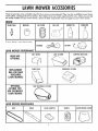
These accessories were available when this lawn mower was produced. They are also available
at most Sears
retail outlets, catalog and service centers. Most Sears stores can order repair parts for you, when you provide
the model number of your lawn mower. Some of these accessories may not apply to your lawn mower.
ENGINE
SPARKPLuG
If lawn
mower
AIR FILTER
MUFFLER
is an electric
GAS CAN
ENGINEOIL
STABILIZER
start
BATTERY __
LAWNMOWERPERF!
_RMANCE
REARBAG
OPTIONAL
DUSTSHIELD
CLIPPING DEFLECTOR
PERMANEXCATCHER
REPLACEMENT
BAGFOR REAR
DISCHARGE
LAWNMOWERS
OPTIONAL
CATCHER
FOR
SIDEDISCHARGE
LAWNMOWER
LEAFCATCHER
SIDE DISCHARGECATCHER
LAWNMOWERMAINTENANCE
WHEELS
LAWN MOWER COVER
ASSEMBLY
Your lawn mower has been assembled at the factory except for the Grass Catcher Bag and the Grass
Catcher Frame.
OPERATOR
CONTROL
u
TO REMOVELAWNMOWERFROMCARTON
*
£RESENCE
BAR
LIFT UP
LIFT UP
/////,'
_,//t
Cut down the corners of the carton and lay ends
and sides down flat.
= Cut the plastic wrapping and remove from over
Handles and lawn mower.
= Remove Catcher Frame, Fabric Bag and Oil Bottle from top of lawn mower.
* Lift lawn mower off of shipping base and check
carton for loose parts.
MOWING
POSITtON
HOWTO SET-UPYOURLAWNMgWER
TO UNFOLDHANDLE
*
*
*
o
o
o
Remove Handle Padding holding Operator
Presence Controt Bar to Upper Handle.
Raise Handles until Lower Handle section locks
into place in mowing position ISee Fig. 1}.
Raise Upper Handle section into place on Lower
Handb and tighten one i1) Handle Knob.
Your lawn mower has been shipped with Protective Handle Pads placed between the upper and
lower sections otthe Handle° For best lawn
mower performance these Pads need to be
discarded after the Handle is placed in the mowing position.
Once the Handle is in the mowing position,
remove the Handle Knob, Handle Bolt and Protective Pad from the side with the loose Handle
Knob. (Make sure the other side is tight to suppart the Upper Handle).
Discard the Pad and reinstall the Handle Bolt and
Knob--Tighten securely.
Loosen and remove the Handle Knob, Handle
Bolt and Protective Pad from the other side and
discard the Pad.
Reinstall the Handle Bolt and Knob-'Tighten
securely, Now your Handles should be clamped
together without the Protective Pads.
Your Lawn Mower Handle can be adjusted for
your mowing comfort. Refer to "Adjust Handle"
in the Service and Adjustment Section of this
manual.
DOOR
GRASS
-
TOASSEMBLE
& ATI'ACHGRASSCATCHER
•
•
Put Grass Catcher Frame into Grass Bag with stiff
part of Bag on the bottom.
• " Stip vinyl bindings over Frame ISee Fig. 2).
NOTE: If vinyl bindings are too stiff, hold them in
warm water for a few minutes, ff Bag gets wet, let
it dry before using.
CATC
FRAME
FIG. 3
Lift the Rear Door on the Lawn Mower Housing
and place the Grass Catcher Frame onto the formed up Tabs on the Rear Door Hinge Bracket (See
Fig. 3).
The Grass Catcher is secured to the Lawn Mower
Housing when the Rear Door is lowered onto the
Grass Catcher Frame.
-
__
CASH
_
YoueLAWH
MOW_e
oRA_ROVeD
[
T.ELAWN
MOWER
W_H
T,_[
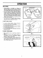
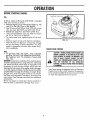
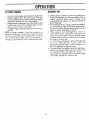
OPERATION
KNOWYOURLAWNMOWER
READ THIS OWNER'S
MANUAL
AND
SAFETY RULES BEFORE OPERATING
pare the illustrations
with your Lawn Mower to familiarize
and adjustments.
Save this manual for future reference.
OPERATOR
CONTROL
yourself
CABLE
with the location
CONTROL
of various
Com-
controls
LEVER
ZONE
_TARTER
HANDLE
HANDLE
CLIP
KNOB
;ABLE
CLIP
ENGINE
GRASS
MOWER.
PRESENCE
DRIVE
ENGINE
CONTROL
YOUR LAWN
CATCHER
---4_
OIL
CAP
_CAP
COVER
PRIMER
AIR FILTER
WHEEL
ADJUSTER
(ON EACH WHEEL)
HOUSING
FIG. 6
MEETS
CPSCSAFETY
REQUIREMEHTS
Sears Rotary Walk-Behind
Power Lawn Mowers conform to the safety standards of the American National
Standards
Institute and the U.S. Consumer Product Safety Commission.
The blade turns when the engine
is running.
OPERATOR PRESENCE CONTROL
BAR - must be
held down to the handle to start the engine. Release
to stop the engine.
DRIVE CONTROL
propelled
forward
PRIMER _ pumps additional
fuel from the carburetor
to the cylinder for use when starting a cold engine.
STARTER
HANDLE
LEVER - used to engage
motion of lawn mower.
- used for starting
power-
the engine.
T
DRIVECONTROL
\
•
Self-propelling
is controlled
by holding the
operator presence control bar down to the handle and pushing the drive control lever forward
until it clicks; then release the lever (See Fig. 7).
o Forward motion will stop when the operator
presence control bar is released. To stop forward
motion without stopping the engine, release the
operator presence control bar slightly until the
drive control disengages. Hold operator presence
controt bar down tohandle to continue mowing
without self-propelling°
To keep drive control engaged when turning corners, push down on handle and lift front whee&
off ground while turning tawn mower.
_
\
\
OPERI TOR
"_COflTROL
.....
PRESENCE
BAF
\
.
_
DRIVE CONTROL
_ CONTROL--4_
DISENGAGED
FIG. 7
_0 EMPTYGR._SSCATCHER
/
o To remove Grass Catcher, release Operator
Presence Contro! Bar to stop engine°
o Lift up Rear Door and remove the Grass Catcher
by the Handle lSee Fig_ 6).
Lift up Rear Door and remove the Grass Catcher
by the Handle (See Fig. 6).
• Do no_drag the Bag when emptying; it will cause
unnecessary wear.
\
\
\
TO ADJUSTCUTTINGHEIGHT
*
*
"
Raise wheels for low cut and lower wheels for
high cut.
Wheels are set in low cut for shipping. Adiust cutting height to suit your requirements.
Medium
position is best for most lawns.
To change cutting height, squeeze adjuster lever
toward
wheel. Move wheel up or down to suit
your requirements.
Be sure all wheels are in the
same setting (See Fig. 8).
FIG. 8
LOWER WHEELS
FOR HIGH CUq r
"
--
-_.I"_'_ "-'P''
RAISE WHEELS
FOR LOW CUT
r
\
I
FIG. 9
T
BEFORE
STARTING
ENGINE
01L:
GASOUNE
F_LLER
CAP
A 20 oz. bottle of Pennzoil SAE 30 Oi! is included
with your new lawn mower.
* Remove engine oil cap with dipstick (See Fig. 10)
and fiJ! to the FULL line on the dipstick.
" Use 20 ozs. of SAE 30 oil. SAE 10W 30 oil can
also be used. DO NOT use SAE lOW 40 oil.
, POUR OIL SLOWLY.
DO NOT OVER FILL.
® Check oil level before each use. Add oil if needed. Fill to FULL line on dipstick.
® To read proper level, tighten engine oi! cap each
time.
o
Replace engine oil cap with dipstick and tighten.
After the first two (2) hours of mowing, change
the oil, and every 25 hours thereafter.
You may
need to change the oil more often under dusty,
dirty conditions.
GAS:
*
Fill gasoline tank with fresh, clean unleaded
gasoline. DO NOT USE PREMIUM GASOLINE.
BE CAREFUL NOT TO OVERFILL TANK (SEE
FIG. 10).
WARNING: Experience indicates that alcohol blended fuels (called gasohol or using ethanol or methanol)
can attract moisture which leads to separation
and
formation
of acids during storage. Acidic gas can
damage the fuel system of an engine while in storage.
To avoid engine problems, the fuel system should be
emptied before storage for 30 days or longer. Drain
the gas tank, start the engine and let it run until the
fuel lines and carburetor
are empty. Use fresh rue)
next season. See Storage Instructions for addifiona_
information.
Never use engine or carburetor
cleaner products
the fuel tank or permanent damage may occur.
in
ENGINEZONE CONTROL
CAUTaON: FEDERALREGULATIONSREQUIREAN
ENGINE CONTROLTO BE INSTALLEDON THIS
LAWN MOWER tN ORDER TO M|NIMIZE THE
ElSE OF BLADE CONTACT INJURY. DO NOT
FEAT. THE
UNDER
ANY FUNCTION
CIRCUMSTANCES
OF THE
ATTEMPT
OPERATOR
TO DECONTROL.THEBLADETURNSWHEN THEENGINE
!S RUNNING.
Your lawn mower is equipped with an Operator
Engine Control Bar which requires the operator
to be positioned
behind the lawn mower handle
to start and operate the lawn mower.
To start a cold engine, push primer five (5) times
before trying to start. Use a firm push° This step
is not usually necessary when starting an engine
which has already
run for a few minutes°
® Hold operator presence control bar down to the
handle and pull starter ha_dle quickly. Do not
o))ow s)arter rape )o snap back.
o To STOP engine_ release operator presence con_
trol bar°
NgT_: in coabr
weather it may be necessary to
repeat priming steps° Jn warmer weather over prim°
ing may cause flooding and engine will not _tart. ff
you do flood engine wait o few minutes before attempting to start and DO NOT repea_ priming steps_
e
Under certain conditions, such as very tall grass_
it may be necessary to raise the height of cut to
reduce
pushing
effort
and
to keep
from
overloading
the engine and leaving dumps af
grass clippings.
For extremely heavy cutting, reduce the width of
cut and raise the rear of the lawn mower hous°
ing one I1) wheel adjuster setting higher than the
front for better discharge of grass.
When using a rear discharge
lawn mower in
moist, heavy grass, dumps of cut grass may not
enter the grass catcher° Reduce ground speed
tpushing speed) and/or run the lawn mower over
the area a second tirae.
ff a trail of grass clippings is left on the right side
of a rear discharge
lawn mower,
mow in a
clockwise direction with a small overlap to col[oct the clippings on the next pass.
The vent holes in the baffle in back of apermanex
catcher can become filled with dirt and dust with
use and the catcher will collect less grass.
To prevent this, reguJarly hose the catcher baffle
with water and let dry before using_
f
GENERAL
RECOMMENDATION
BLADE
o Once a year you should replace the spark plug,
air filter and check blade for wear. A new spark
plug and air filter assures proper air-fuel mixture
andheIps your engine run better and last longer.
+ You should check al! fasteners and be sure they
are tight.
• Follow the Service Recommendation
Schedule on
page 18.
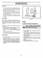
,ADAPTER
DETAIL
CRANKSHAFT
__+[-_//
[--_-
&
ASHER
_BLADE
BLADE
ADAPTER
BOLT/_(
CRANKSHAFT
tl
LOCKWASHER
LAWHMOWER
BLAD[/BLAD[ ADAPT+:RCARE
Your lawn
blade.
mower
will
work
better
with
F|G. 1 ]
a sharp
TH HESPARK
I
+
The recommended
+bs.
+
Torque wrenches are avai[abJe
stores and through the cataJog°
TO REMOVE BLADE:
® Turn lawn mower on its side. Make sure air fi!fer
+
and carburetor
are up.
Use black of woad between
blade
and
lawn
mower housing to prevent blade from turning
when removing the blade bolt.
+ Protect your hands with gloves and/or
wrap
blade with heavy cloth,
+ Remove blade bolt by turning counterclockwise.
Use a 9/16"
box or open-end wrench°
+ Remove blade and attaching
hardware
(bolt,
Iockwasher and hardened washer) (See Fig. 11).
NOTE: Remove the blade adapter and check the key
inside hub of blade adapter. The key must be in good
condition
ta work properly°
Replace adapter
if
damaged.
TO REPLACE
Position
the btade
adapter
on the engine
crankshaft.
Be sure key in adapter and key way
in crankshaft are aligned,
+ Position blade on ta the blade adapter aJigning
the two {21 holes in the blade with the raised tugs
on the adapter+
NOTE: Be sure the word TOP (stamped on the bladel
is toward the engine (See Fig. ] ]!°
® Install the blade boh with the tockwasher
and
washer
into blade
adapter
(See F+9. 11).
of wood between blade and
mower housing
ing clockwise°
torque
is 35-40
ft,
at most Sears
LOOS[BLAP[ (AH B[ DAHG[ROU__I
..............
Use only a Sears authorized
replacement
blade ta
get the best cutting results,
NOTE: We do not recommend sharpening blade - but
if you do, be sure the blade is balanced.
TO SHARPEN
BLADE:
+ The blade can be sharpened with a file or on a
grinding
wheel. Da nat attempt ta sharpen wh+te
on the town mower.
+ Care should be taken to keep the blade balanc+
edo An unbalanced
blade will cause excessive
BLADE:
+
hardened
crankshaft
® Use block
_A
tightening
and
lawn
and tighten the btade bah, turn-
vibration
when running and eventual damage ta
lawn mower or engine.
+ To check blade balance, drive a nail into a beam
or watto Leave about one inch of the straight no+!
exposed. Place center hole of blade aver the head
of the nail. ff btade is balanced,
it should remain
in a harizanta! position. If either end of the blade
moves downward,
blade
is not balanced°
Sharpen
the heavy
end until the blade
is
balanced.
Tokeepyour drive systemworking properly, th÷
gear caseand area around the drive shouldbe
keptcleanandfreeof trashbui_doup.
Cleanunder
the drive
cover twice a season°
The gear case is filled with bbricant
to the proo
per level at the factory° The only _ime the _ubrio
cant needs ettention is if service has been perFormed on _he gea_ case°
tf bbricant
is required, use only Texaco Sterptex
Premium 1 Grease, Part No° 750355.
Do Not
substitute.
INER
DRIVEWHEELS
FIG° 12
Checkfront
drive wheels each time before you maw
to be sure they move freely. The wheels not turning
freely means trash, brass, cuttings, etco ere in the
drive wheel area and must be cleaned to free drive
wheels.
If necessary _o clean the drive
front wheets.
*
*
*
Remove
Remove
Remove
the dust
teeth.
wheels,
check both
hubcaps, hairpin cotters and washers.
wheels from wheel adjusters.
any trash or grass cuttings from inside
cover, pinion and/or drive wheel gear
® Remove engine oil cap with dipstick;
e clean surface.
® Put wheel_ back in piece.
* If after denning, the drive wheels do not turn freety, contact your nearest Seers Service Center.
® Tip lawn mower on its side as shown in Fig. 12
and drain oi! into suitable container. Rock|own
mower back and forth to remove any oil trapped
inside of engine.
* Wipe off any spilled oil on lawn mower and on
side of engine.
'_ Fill engine with SAE 30 or 10W 30 oil. Fill only
to the "FULL"
line on the dipstick° DO NOT
overfill.
_6EASSCATCHER
may be hosed with water, but must
be dry when used.
Check your grass catcher often for damege or
deterioration. Through normal use it wil! wear.
If catcher needs replacing, replace only with a
manufacturer approved replacement catcher from
Sears. Give the lawn mower model number when
ordering.
The catcher
®
lay aside on
e
o
12
Replace engine nil cap.
Reconnect spark ptug wire
to spark
plug.
AiR FILTER
COUNTER-CLOCKWISE
TO REMOVE
Your engine will not run properly and may be
damaged
by using a dirty air filter.
Replace the air filter every year, more often if you
mow in very dusty, dirty conditions. Do not wash air
filter.
TO CHANGE
*
*
*
o
*
,
AIR
FILTER
TURN CLOCKWISE
TO TIGHTEN
Remove the air filter cover by turning counterclockwise to the stop and puHaway
from collar
(See Fig. 13).
Remove filter from inside of cover (See Fig. 13).
Clean the inside of the cover and the collar to
FiG. 13
remove any dirt accumulation.
tnsert new filter into cover.
Put air filter cover and filter into collar aligning
the tab with the slot.
Push in on cover and turn clockwise to tighten (See
Fig. 13).
•
Turn lawn mower on its side with carburetor
up.
Clean the underside
of your lawn mower by
scraping to remove build-up of grass and trash.
• Clean your lawn mower and engine often to keep
trash from accumulating around engine. A clogged engine runs hotter and shortens engine life.
® We DO NOT recommend using a garden hose
to clean lawn mower unless the electrical system,
muffler, air filter, and carburetor
are covered to
keep water out. Water in engine can result in
shortening engine life.
SPARKPLUG
Change your spark plug each year to make your
engine start easier and run better. Set spark plug
gap at .030 inch.
CLEANING
We recommend that you clean the underside
lawn mower after each use.
of your
CAUTION: DISCONNECTSPARK PLUG WIRE
d_
FROM
SPARKPLUG
PLACEWIRE WHERE
IT CANNOT
COME INAND
CONTACTWITH
SPARK
PLUG.
13
ANDADJUSTMENT
TO REMOV_REPLACEDRIVE BELT
_
CAUTION: DISCONNECT
SPARKPLUGWIREFROM I
^
/HE×
_-
I _
HEAD
SCREW
BELT
SNUBBER
SPARKPLUG. PLACEWIRE WHEREiT CANNOT
J
APPROX
,
Remove drive cover. Remove belt by pushing
down on gear case putley (See Fig. 14).
Turn lawn mower on its side with carburetor
and
•
fuel cop up.
Loosen hex head screw and move belt snubber
•
1
PRESS
/
i
away from pulley (See Fig, 14).
Remove betelfrom engine pulley on crankshaft and
carefully slip belt off over blade.
CAUTION:
Sharp edges of blade can cut belt.
Install new belt reversing above steps.
Move belt snubber back in place and tighten hex
head screw.
I
FiG. 14
NOT[: Belt snubber clears belt by approx.
1/32 inch
when installed.
- Always use factory approved
belt to assure fit
and long life,
IERS
SLEEVE
ARM
_ABL_ CLAMP
l[-IIt
TO &DJUSTDRBVECONTROLCABLE
SCREW
"A"
©
A drive contrd cable that needs adiustment will keep
your awn mower from self-prope ling properly and
can also cause gear case components to wear out
l
"ADJUSTING
BRACKET
RO'TATE
I
I
CLUTCH
SPRING
sooner_
Remove drive cover.
Loosen cable clamp screw "A"
IICI'
and nuts "B"
FIG. t 5
and
"
EHGIN[ SPEED
Hold down operator presence control bar to ham
die and engage drive control.
Move shifter arm to drive position while rotating
front wheels to be sure aw clutch is engaged. Pull
threaded seeve with piers (See Fig. 15). Do NOt
pull on contro! cable.
• Tighten nut "C" until sleeve is snug.
® Tighten screw "A"
and nut "B".
• Push lawn mower back and forth to be sure gear
case is engaged.
• Replace drive cover.
• Release operator
presence control bar.
Your engine speed has been factory set. Do not attempt to increase engine speed or it may result in personal injury. If you believe that the engine is running too fast or too slow, take your lawn mower to
an authorized
Sears Service Center for repair and
adjustment;
REARDEFLECTOR
The rear deflector,attached
between the rear wheels
of your lawn mower, is provided
to minimize the
possibility
that objects will be thrown out the rear
of the lawn mower
into the operator's
mowing
position.
CARBURETOR
Your carburetor has a non-adjustable
fixed main jet
for mixture control. If your engine does not operate
properly due to suspected carburetor problems, take
your lawn mower to an authorized
Sears Service
Center for repair and adjustment.
if the rear deflector
replaced.
14
becomes damaged,
it should be
SERVICE
ANDADIUSTMENT
i
TO ADJUST
HANDLE
Your lawn mower handle
can be raised
or lowered
SHIPPING
for your mowing comfort. Figs. 16A, 16B, 17A and
17B show the four (4) positions that are available:
High, medium high, medium low and low. Handles
are shipped mounted in the medium low position (See
Fig. 16A)
_, To change from medium low to medium high position, the upper and lower handle sections will
have to be turned over (See Fig. 16B).
Remove the controls and operator presence control bar from the upper handle.
Remove the starter rope guide from the lower
handle.
Remove hairpin cotters.
Disconnect the lower handle from the handle
POSITION
MEDIUM
III1[
brackets (See Fig. 18).
Turn the handle over and reassemble the hairpin
cotters that have been removed (See Fig. 18).
Reassemble the starter rope guide.
Reassemble
the controls
and the operator
presence control bar to the upper handle.
LOW
MEDIUM
HIGH
FIG. ]GA
FiG. 16B
FIG, ] 7A
FIG. 17B
I
CAUTION: THEOPERATORPRESENCE
CONTROL
BAR MUST PIVOT FREELYTO PERMIT BLADE
BRAKEENGAGEMENT
CONTROLBAR
IS
RELEASED. DO NOTWHEN
OVERTIGffTEN
THE
FASTENERS
HOLDING THE CONTROLSTO THE
UPPERHANDLE.
To change from medium low to
ly the upper handle section will
ed over (See Fig. 17A)°
To change from medium low to
ly the lower handle section will
ed over (See Fig. 17B).
high position onhave to be turnlow position, onhave to be turn-
LOWER
\
HANDLE
t
HAIRPIN
COTTER
HANDLE
FIG. 18
15
BRACKET
Your lawn mower and engineshouldbe prepared
for off-seasonstorageas follows:
OPERATOR
CONTROL
PRESENCE
BAR
LAWNMOWER
UPPER
*
Clean underside of lawn mower housing. (See
:'Cleaning"
in maintenance section of manual.)
,_ Inspect and replace/sharpen
blade, if required
(See
"Blade/Blade
Adapter
Care"
in
maintenance
section of manual).
', Hose grass catcher off with water and let dry
before storing.
. Lubricate as shown in Service Recommendation
chart on page
FOLDFORWARD
FOR STORAGE
/
FOLD
BACKWARD
)WING
POSITION
18 of manual.
LOWER
HANDLE
_' You can fold your lawn mower handle for storage
as shown in Fig. 19.
o To fold, squeeze the bottom ends of the lower
handle toward each other until the lower handle
clears the handle bracket, then move handle for_
ward (See Fig. 20).
IMPORTANT: WHEN FOLDINGTHE
HANDLE FOR
STORAGE OR TRANSPORTATION,
BE SURE TO FOLD THE HANDLE AS
SHOWN
IN FIG. 19. IF YOU FOLD
THE UPPER HANDLE SECTION THE
WRONG
WAY, YOU MAY DAMAGE
THE CONTROL
CABLES.
H/
NDLE
FIG° 19
.\
LOWER
HANDLE
HANDLE
HAIRPIN
BRACKET
COTTER
ENGMNE
Change oil (See "To Change Oil" in maintenance
section of manual).
o
Drain Fuel and Run Engine until fuel system is
empty.
iMPORTANT: IT IS IMPORTANT
TO PREVENT
GUM DEPOSITS FROM FORMING
IN ESSENTIAL FUEL SYSTEM PARTS
SUCH AS THE CARBURETOR,
FUEL
FILTER, FUEL HOSE, OR TANK DURING
STORAGE.
ALSO,
EXPERIENCE INDICATES
THAT ALCOHOL
BLENDED
HaL
OR
FIG. 20
OTHER
°
•
Do not store gasoline from one season to another.
Replace your gasoline can if your can starts to
rust. Rust and/or dirt in your gasoline can cause
problems.
'_ Do not store your lawn mower under any plastic
cover. Plastic cannot breathe which allows condensation
to form and can cause your lawn
mower to rust.
When setting up your handle from the storage
position, thebwer
handle will automatically
lock
into the mowing position.
FUELS (CALLED GASOUSING
ETHANOL
OR
METHANOL)
CAN ATTRACT MOISTURE WHICH
LEADS TO SEPARATION AND FORMATION
OF ACIDS
DURING
STORAGE.
ACIDIC
GAS
CAN DAMAGE
THE FUEL SYSTEM
OF
AN
ENGINE
WHILE
IN
STORAGE°
16
_E#UL[
SERVt¢E
DATES
Fit! _ndates as you compbte regdGr
First
Service
2
Hours
Every
Every
10
Harts
25
Every
Use
Haurs
L_lode Checked
Blade
replaced
{Sharpened)
J
Engin_ Off Change
J
Engine Oil Check
J
Air CbQner
Spark Plvg Replaced
Lubricate Lawn Mower
Cleaning
/t
Grass Catcher (if applicable}
J
Muffler
v"
- cHEcK
LUBRICATION
CHART
SAE 30 MOTOR OIL (lOW
SPRAY
BRAKE
SPRING
30)
LUBRICANT
BRACKET
ENGINE
OIL
HANDLE BRACKET
MOUNTING
PIN
REAR
DOOR
HINGE
WHEEL
17
ADJUSTER
T
PROBLEM
DOESHOT
START
TS
CAUSE
I.
2.
3.
4.
5.
6.
7.
8.
9.
LOSSOF
POWER
t.
2.
3.
4.
5.
6.
CORRECTION
Dirty air filter.
Out of gasoline.
Stale gasoline.
Spark plug wire is disconnected
from the spark plug.
Bad spark plug.
Water in gasoline°
Loose blade or broken blade
adapter,
Operator presence control bar in released position.
Operator presence control bar defective.
1, Replace air filter
2. Fitt gasoline tank.
3. Drai.n gas tank and refill with fresh
gasoline.
4. Connect wire to spark plug,
5, Replace spark plug.
6. Drain tank and refill with fresh, clean
gasoline.
7. Tighten blade bolt and/or replace
blade adapter.
8. Depress operator presence control bar
9. Replace operator presence control bar
Rear of lawn mower houslng/biade
dragging in heavy grass,
Cutting too much grass.
Dirty air filter
Build-up of grass, leaves, end
trash under !awe mower housing.
Walking speed too fast,
Too much eli in engine.
1. Raise rear of lawn mower housing one (t)
setting higher than front.
2. Set in H_GHER CUT position.
3. Cleon or replace air fiher.
4. Disconnect spark plug wire and
dean underside of lawn mower houslng,
5_ Cut at sJower walking speed.
6. Check engine oil level.
Worn, bent or loose blade,.
Wheet heights uneven.
Low engine speed.
Build-up of gross, leaves and trash
under town mower housing.
1. Replace blade, T_ghten blade bah.
2o Set all wheels at same height,
3. Set engine speed centre! in
HIGH position.
4_ Disconnect spark plug wire & clean
underside of lawn mower housing.
POOR (UTUREV[[_
1.
2.
3.
4.
TOO MUCH
VIBRATION
1. Worn or bent biadeo
2, Loose blade.
3. Bent engine crankshaft,
i Replace blade.
2. Tighten blade bolt.
3. Contact Sears Service Department.
STARTERROPE
HARD TO PULL
1_ Flywheel brake is on when operator
presence controf bar is released.
2. Bent engine crankshafl.
3_ Blade adapter sheared.
4, Biade dragging in grass.
1
Depress operator presence control
bar to upper handle before pulting
on starter rope.
2. Contact Sears Service DepartmenL
3. Replace blade adapter.
4. Get over Jaw gross and/or hard surface
to start engine.
_AT(H_RROT
FILL!NG
COMPLETELY
1. Cutting height too tow,
2. Lift on blade worn off.
3. Catcher bag dirty, poor air
venting,
4. Low engine speed.
1, Raise cutting height.
2, Reptace blade.
3. Clean/replace catcher bag_
(ff optionat grass catcher is being
used).
4, Set engine speed control in
HiGH position.
HARD TO PUSH
1. High grass or cutting height too low
2. Rear of !awe mower housing/blade
dragging in heavy grass.
3. Grass catcher too full,
4_ Hondie height position not r_ght for you.
_8
]. Raise cutting height.
2. Raise rear of lawn mower housing one (1}
setting higher than front.
3_ Empty grass catcher_
4o Adiust handle height to suit.
N©TES
]9
CRAFTSMAN
22"
ROTARY
LAWN
MOWER
MODEL
NUMBER
/
P_
O
917.372490
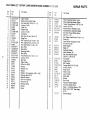
REPAIR PARTS
CRAFTSMAN
Ref.
No,
h_
!
2
3
4
5
6
7
8
9
10
I1
!2
13
14
15
16
17
!8
t9
20
22
23
24
25
26
27
28
29
30
31
32
33
34
22"" ROTARY
LAWN MOWER
MODEL NUMBER
Part
No.
Part Name
850991X479
851667
Upper Handle
Engine Zone Control Cable
Hex Head Bolt 1/54-20
X 1-1/2
Locknut
1/4-20
Cabte Clip
Handle Knob
Locknut
I/4-20
Control
Bar
Rear Door Kit find, Ref, #10)
Hinge Rod
Self Tapping
Screw 10-24 x 5/8
Hex Tapping
Screw 1/4-20 x 1/2
Hex Head Screw
1/4-20 x 3/4
Back Plate
Side Baffle
Discharge
Baffle
Rear Baffle
Truss Head Screw 10-24 x 1/2
Locknut
10-24
Rear Skirt
Engine Pulley
Hi-Pro Key #505
Hubcap
Retainer Clip
Washer
Wheel & Tire Assembly
8.00 x 2.00
Shoulder Bolt 3/8-t6
Belleville Washer
Axle Arm Assembly
Selector Knob
Selector Spring
Washer
Spacer
STD522515
STD541425
85827
63688
STD541425
851509
¢8137
750328
67215
8TD512505
54583
88644X479
750480X479
88668X479
87596X479
STD511005
STD541410
751083
85543
87677
77400
85179
52180
87748
84921
62335
85022
87877
850856
88348
84920
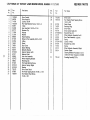
REPAIR PARTS
917o372490
Refl
2_
35
36
37
38
39
Part
No,
850923
850924
55187
STD541431
86912X417
86913X417
850998
_2
_3
44
750097
87930
48173
46
47
48
49
5O
851514
51
52
53
54
87587X479
85463
851000
STD533t07
74400
88652
51793
84676X479
58714
851219
!03672X
750627
750635
752191
52
58
57
58
58
60
61
62
63
64
851074
850263
851084
752193
Part Name
Wheel Adjusting
Bracket (Right)
Thread
Cutting Screw 5/16-!8
x 3/4
Locknut
5/16-! 8
Handle Bracket Assembly
(Left)
Handle Bracket Assembly
(Right)
Hex Head Thread Rolling Screw
3/8-!6
x 1-1/8
Hex Washer Head Screw 10-24 x 1/2
Guide Clip
i Lawn Mower
Housing (Inc!. Ref.
#14,15,51
& 52)
Blade Adapter
Blade 22"
Hardened Washer
Helical Washer 3/8
Hex Head Machine Screw
3/8-24
x 1 3/8 Grd. 8
Front Baffle
Danger Decal
Belt Snubber
Carriage Bolt 5/16-18
x 5/8
Locknut
3!8-16
Hinge Screw
Hairpin Cotter
Lower Handte
Handle Bolt
Washer
Rope Guide
Instruction
Decal (Engine)
hstruction
Decal (Drive)
Engine - Craftsman
Mode_ 143.414302
25-27)
Owners
Manual
(Source 143)
(See Pages
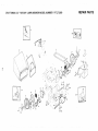
CRAFTSMAN
22"
ROTARY
LAWN
MOWER
MODEL
NUMBER
REPAIR
917.372490
PARTS
25
I
[
27
/
28
35_
CRAFTSMAN
P_
Ref,
No.
Part
1
2
3
4
5
6
7
8
9
10
11
12
13
1-4
15
18
!7
t8
19
20
21
22
23
24
25
26
27
750560
48029
74189
750029
83691
54338
85179
77400
52160
86920
87729
53753
74507
76401
86273
86274
851020
87877
88285
850922
58922
61528
851022
851226
751031
87866
750097
22"
ROTARY
LAWN MOWER
MODEL NUMBER
Part Name
No.
Drive Control
Drive Head Kit
Locknut 10-24
Pan Head Machine Screw 10-'24 x 2
V-Belt
Hex Head Bolt 1/4-20 x 2 3/4
Retainer Clip
Hubcap
Washer
Nylon Bushing
Wheel & Tire Assembly 8.00 x 2.00
E-Ring
Pinion
Dust Cover
Spacer Bearing
Believille Washer
Selector Spring (Left)
Selector Knob
•Axle Arm Assembly
Wheel Adjusting Bracket
Retaining Clip
Flat Head Machine Screw
Selector Spring (Right)
Washer
Drive Cover Decal
Pan Head Tapping Screw 10-24 x 2 3/4
Hex Washer Head Screw
10-24 x 3/8
REPAIR PARTS
917,372490
Ref.
No.
Part
No.
Part Name
28
29
750293
750108
30
31
32
33
34
35
36
37
38
39
40
41
52
53
83700
74976
83681
48176
STD580014
48175
48184
83632
STD541425
57076
75192
48174
88614
Drive Cover
Hex Washer Head Tapping Screw
10-24 x 3/8
Cable Clamp
Retaining Ring
Drive Pulley
Drive Control Cable Kit
Woodruff Key #3
Wheel Adjuster Assembly (Left)
Gear Case Assembly _,_ Z_L
Spring
Locknut 1/4-20
Woodruff Key #2 ! 3
Spring
Wheel Adjuster Assembty (Right)
Catcher Frame
Clipping Deflector Accessory (not included with lawn mower) 7=1 33303
54
751663
Grassbag AssembJy 2.0 Bu.
22 '° POWER-PROPELLED
LAWN
MOWER
917,3t2490
REPAIRPARTS
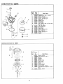
GEAR CASEASSEMBLYPART NUMBER751001
22
Part
No.
Part Name
Ref.
No.
Pare
No.
Part Name
I
2
3
4
5
6
53838
85178
88386
57072
57388
48032
KopsL_knut 1/4-20
AdlustingBracket
ShifterAssambJy
7
B
9
10
11
77881
77039
750430
57079
75144
12
13
14
15
16
17
18
19
20
21
22
87822
86447
83659
750436
750355
STD581050
850848
83720
65692
83680
50950
23
751046
GroovedPin 1/8 x 3/4
Plug
Helical Gear
Jaw Clutch
Grease
E-Ring
Hi-Pro Key
Worm _aff
Weed_tf Key #3
Worm
Hax Heed MachineS_rew
1/4-20 x I 114
Identification Tag
Rat.
NO.
Grooved Pin 1/8 x 112
Gear CasoHalves(inc. Upper&
LowerHalves) find°Rof. 4, 5, 7)
hating
SpringBracket
Drive Shaft
Harden_ Washer
Yake Clutch
CARBURETOR
NO.
632078A
Part
Ref.
632078A
631615
631616
Carburetor
Shaft _ Lever Assy., Throttie
Shutter, Throttle
650506 Screw, Throttle shutter
631767
Spring, Throttle return
631971
Seal, Dust
631184
Washer, Fiat
632047 Primer Assy.
631027
Plug, Welch
631021
Iniet NeedJe, Sest _ CJip Assy.
(IncL No. 13)
631022 Clip, inlet needle
632019 Float, Carburetor
631024 , Shaft, Float
631700 t Bowl, Float
631334 Gasket, Bowl-to-body
631937 Nut, Float Bowl
631028 Gasket, Bowl-to-body
631807 I F_tting, Fuel inlet
632158 .[ Spacer
1
3
4
5
6
7
9
1t
12
9
Part Name
NO.
No.
!
I
/
J
J
_J
REWIND
STARTER
NO. 590621
---r--Ref. ! Part
No. t No.
_
....
_©>
3
2
25
Part
Name
590621
1 ! 590599,
21590000
3 I 5,90615
4 1590601
5 I &90598
6 I 590616
7
590617
8
590618
9
590619
10
590620
11
590622
12 t 590635
Starter, Rewind
Pin, Spring (Incl. No. 4)
Washer
Retainer
Washer
Spring, Brake
Dog, Starter
Spring, Dog
Pulley
Spring, Rewind
Cover, Spring
Housing Assy.
Starter
Rope, Starter (Length 98" 8 9/64"
dia.)
!3
Handle,
_
Starter
MODELandSERIAL
NUMBERSHERE
189"\1_4""--
-7
130
101
"\
126
.
/
120
192
_2_%
193
""- 3!o
!82,
I
19
/
0---.307
2O7
185
/
178
28
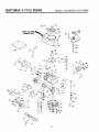
C rTSMAN 4-CYCLEENGIHE
P_t
No.
33968B
26727
33734
34214A
*33735
30200
34695
33886
28277
30589
31383A
31335
650548
31361
32600
35801
34535
34536
34537
33562B
33563B
335648
33567
33568
33569
20381
32875
32610A
27241
33553
29814
*35261
34311C
30572
*28833
27897
30574
30590A
30591
30588A
29193
650488
611004
611108
650815
650816
34443A
610118
650814
34961
"33554A
34342
29313C
29315C
28314B
29315C
6021A
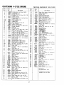
MODEL
Part Name
Cylinder Assy. (Incl. Nos. 8 8- 20)
Pin, Dowel
Element, Breather
Breather Assy. (Incl. Nos. 6, 8, 9, 12A
8- 128)
Gasket, Breather
Screw, Hex washer hd. self-tap Seres,
10-24 x 9/16
Elbow, Breather tube
Tube, Breather
Washer, Flat
Rod, Governor (Incl. No. 14)
Lever, Governor
Clamp, Governor lever
Screw, Hex washer hd., 8-32 x 5/16
Spring, Extension
Seal, Oil
Crankshaft Assy.
Piston,
Pin 8- Ring
Assy.
(Std.)
(incl. Nos. 41, 42 8 43)
Piston, Pin 8- Ring Assy. (.010 oversize) (Incl. Nos. 41, 42 & 43)
Piston, Pin 8- Ring Assy, (.020 over °
size) (tncl, Nos, 41, 42 8- 43)
Piston 8 Pin Assy. (Std,) (Incl. No. 4.3)
Piston
8- Pin Assy.
(.010 oversize)
(Incl. No. 43)
Piston
8- Pin Assy.
(.020 oversize)
(Incl. No. 43)
Ring Set, Piston (Std,)
Ring Set, Piston (.010 oversize)
Ring Set, Pie%on (.020 oversize)
Ring, Piston pin retaining
Rod Asey., Connecting
(Inclo No, 46)
Bolt, Connecting
rod
Valve, Lifter
Camshaft
(Mech.
Compression
Release)
Pump Assy., Oil
Gasket, Mounting
flange
Fiange, Mounting
(Inc!. Nos. 72, 73, 75
8 80)
Plug, Oil drain (Incl. No. 73)
Gasket, Oil p{ug (Not required
with
plastic oit ptug)
Seal, Oil
Shaft, Governor
Washer, Fiat
Gear Assy., Governor (Incl, No. 81)
Spool, Governor
Ring, Retaining
Screw, Hex hd. Seres, 1/4-20 x 1-1/4
Key, Flywheel
Flywheel
Washer, Bellevilte
Nut, Flywheel
Solid State Assy.
Cover, Spark plug
Screw,
Torx T-15 hex washer
hd.
Seres, 10-24 x 1
Wire, Ground
Gasket, Cylinder head
Head, Cylinder
Valve, Exhaust (Std.) (Incl. No. 15!)
Valve, Exhaust (1/32"
oversize) (Incl.
No, 151)
Valve, Intake (Std.) (Incl. No. 151)
Valve,
Intake
(1/32"
oversize)
Incl. No. 151)
Screw, Hex flange hd,, 5/16-18 x 1-1/2
Ref.
Part
NO.
No.
135
35395
150
151
169
!72
174
178
182
184
185
186
189
31672
31673
"27234A
32755
650128
29752
6201
*26756
31384A
32653
650839
190
191
192
193
194
195
207
216
223
224
238
35831
35040
34966
34.965
32309
610873
34.336
33O86
650451
"3469OA
650932
239
241
245
250
260
261
*34338
353'97
35066
35065
3&393A
30200
262
650831
275
276
277
285
287
290
292
298
34613
33753
650795
35000
850884
30705
26460
28763
300
301
305
306
307
308
34369A
35355
35577
34265
35499
650562
310
313
327
357
380
39O
4OO
35578
34080
35392
34985
632078A
590621
3374OD
NUMBER
Part
143,414302
Name
Spark Plug, Resistor (Champion
RJ19LM or equivalent)
Spring, Valve
Cap, Lower vane spring
Gasket, Valve spring box
Cover, Valve spring box
Screw, Hex hd. Seres, !0-24 x I/2
Nut 8- Lockwasher,
I/4_28
Screw, Hex hd., 1/4.-28 x 7/8
Gasket, Carburetor
Pipe, intake (Incl. No_ 224)
Link, Governor spring
Screw,
Hex washer
hd. Powerlok,
1/4-20 x 3/8
Lever, Brake
Bracket, S.E. Brake /hcl. No. 195t
Link, Control
Sprig,
Extension
Rin_ta
_ ng
er_in a_s_y;,'
Lin
[t_ _!i
Lever, Sp'e_d;;-_jus_!ng
;;
Screw
Hex hd Se_s_ _/4-2# x !
Gasket, Intake pipe
Screw,
Hex washer
bd. shoulder,
10-32 x 48/64
Gasket, Air cleaner
Collar, Air cleaner
Filter, Air cteaner (Paper)
Cover, Air cleaner
Housing, Blower
Screw, Hex washer hd, self-tap Sems,
10-24 x 9/I6
Screw,
Hex washer
hd.
Power_ok
thread, 1/4-20 x 15/32
Muffler Assy°
Plate, Lock
Screw, Hex hd., !/4-20 x 2-1/4
Hub, Starter
Screw, Hex washer hd., 8-_ x 1/2
Line, Fuel
Clamp, Fuet tine
Screw,
Hex washer hd. shakeproof,
10-32 x 35/64
Tank_ Fuel (hcL Nos. 2£2 8 301)
Ca
:%
Tu_
Oii
!:
Ga et IFI
0
Ring ......
Screw,
Hex washer hd. shakeproo[,
10-32 x 1/2
Dipstick,
Oil fill
Spacer, Flywheel key
Plug, Starter
Retainer, Starter rope
Carburetor
(hcL No, 184)
Starter, Rewind
Gasket Set (Incl, items marked ")
RPM Setting:
High Speed: 2£00 -. 3200
*Indicates Parts included in
Gasket Set, Ref. No. 400.
27
®
5.0 HORSE POWER
MODEL NO.
917.372.490
22" REAR BAGGER
POWER PROPELLED
ROTARY LAWN MOWER
Each Lawn Mower has its own model number.
engine has its own model number.
Each
The model number for your lawn mower will be found on
a decaJ attached to the rear of the lawn mower housing.
The model number for the engine wiEI be found on the
Blower Housing of the engine adjacent to the spark plug.
AJl parts listed herein may be ordered through Sears,
Roebuck and Co. Service Centers and most Retail Stores.
WHENORDERING
R[PAIRPARTS,ALWAYSGIV[ THEFOLLOWING
iNFORMATION:
* PRODUCto "ROTARY LAWNMOWER"
HOW TO ORDER
REPAIRPARTS
* MODELNUMBER- 917.372490
* ENGINE= CRAFTSMAN
MOD[L NO. 14.3.414.302
* PARTNUMBER
* PARTDESCRIPTION
Your Sears merchandise has added value when you con=
sider that Sears has service units nationwide staffed with
Sears trained technicians...professional
technicians
specifically trained on Sears products, having the parts,
tools and the equipment to insure that we meet our pledge
to you, we service what we sel!.
752.193
10/05/90
Printed in LLS.Ao