1
0
'S MANUAL
I:RRFTSMRI!
®
6=5 Horsepower
2500
2,7
High Pressure Washer
Model No:
919.762500
o Safety
o Assembly
o Operation
o Maintenance
o Parts List
WARNING:
Before using this
product,
read
this manual
and foIIow
ai| Safety
Rules
and Operating
instructions,
..... /i_
Sears,
15300
_GP-7_2500A
Roebuck
Rev, 4/_5/98
and
Co.,
._
HoffmaR
_',_//
Estates,
"_"
EL 60179
o Espanoi
U.SoA=
TABLE OF CONTENTS
Warranty
Safety
............................................
Guidelines
2
..............................
Storage
.................................................
3-5
TrouMeshooting
....................................
t5
t6
Assembly
..........................................
5-7
Parts ................................................
17-28
Operation
..........................................
8-11
EPA Codes ......................................
29-30
......................................
12-14
Maintenance
Service
and Adjustments
LIMITED
..................
ONE YEAR WARRANTY
15
ON CRAFTSMAN
How to Order Parts ............... Back Cover
EspaSol
...........................................
HIGH PRESSURE
WASHER
For one year from the date of purchase, when this Craftsman High Pressure Washer is maintained
and operated according to the instructions in the owner's manual, Sears will repair, free of charge,
any defect in material and workmanship.
If your Craftsman Pressure Washer is used for commerical or rental purposes, this warranty
applies only for 90 days from the date of purchase.
LIMITED
ONE YEAR WARRANTY
ON CRAFTSMAN
ENGINE
Maintenance, replacement or repair of the emission control devices and systems may be performed by any nonroad engine repair establishment or individual. However, to obtain no charge
repairs under the terms and provisions of Craftsman warranty statement, any service or emission
contro! part repair or replacement must be performed by an factory authorized dealer.
For one year from the date of purchase, when this Craftsman engine is maintained and operated
according to the instructions in the owner's manual, Sears wil! repair, free of charge, any defect in
material and workmanship.
If your Craftsman engine is used for commericaf or rental purposes, this warranty applies onlyfor
90 days from the date of purchase. This warranty does not cover: Expendable items such as
spark plugs and air filters, which become worn during normal use.
Repairs necessary because of operator abuse or negligence, including damage resulting
from no
water being suppiied to pump or failure to maintain the equipment according
to the instructions
contained in the owner's manual, are not covered under warranty.
WARRANTY SERVICE _SAVAILABLE BY RETURNING THE HIGH PRESSURE WASHER TOTHE
NEAREST SEARS SERVICE CENTER/DEPARTMENT
THROUGHOUT THE UN}TED STATES.
This, warranty gives you specific
state to state°
Sears,
Roebuck
legal rights and you may atso have other rights, which
a#d Co,, D/817 WA, Hoffma_
Estates,
_L 601 79
vary from
32-50
SAFETY
GUIDELINES
- DEFINITIONS
This manual contains information that is important for you to know and understand. This information relates to protecting
YOUR SAFETY and PREVENTING EQUIPMENT PROBLEMS. To help you recognize this information, we use the symboIs
below. Please read the manual and pay attention to these sections. SAVE THESE DEF_N_T_ONSiINSTRUCT|ONS.
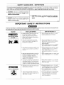
_, WARNING indicates a potentially hazardous
situation which, if not avoided, could result in
death or serious inju_,
A CAUTION
indicates
which, if not avoided,
a potentially
hazardous
situation
_
result in minor or moderate
_i, DANGER indicates an imminently
hazardous
situation which, if not avoided, will result in
death or serious _.
1_2_7
IMPORTANT
SAFETY
INSTRUCTIONS
improper
operation
or maintenance
of this product could result in serious
and understand
all warnings
and operating
instructions
before using.
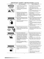
WHAT CAN HAPPEN
HAZARD
RISK OF EXPLOSION
OR FIRE
.
injury and property
damage.
HOW TO PREVENT
Read
iT
Spilled gasoline and its vapors can
become ignited from cigarette
sparks, electrical arcing, exhaust
gases, and hot engine components
such as the muffter.
. Shut off engine and allow it to cooi
before adding fuel to the tank.
Heat will expand fueI in the tank
which could result in spillage and
possible fire explosion.
Use care in filling tar_,k to avoid
spilling fuel. Move pressure washer
away from fueling area before
starting engine.
* Keep maximum fuel !eve! _'_" below
top of tank to allow for expansion.
Operating the pressure washer in an
explosive environment could result
in a fire.
e Operate and fuel equipment
in welt
ventilated areas free from obstructions. Equip areas with fire
extinguishers
suitabIe for gasoline
fires.
= Never operate pressure washer in an
area containing dry brusb_ or weeds.
Materials placed against or near the
pressure washer can interfere with
its proper ventilation features
causing overheating and possible
ignition of the materials.
Improperly stored fuet could Iead to
accidental ignition. Fuel improperly
secured could get into the hands of
children or other unqualified persons.
Breathing exhaust fumes will cause
serious injury or death.
R|SK TO BREATHING
Some cleaning fluids contain substances which could cause injury to
skin, eyes, or lungs,
• Store fuel in container approved for
gasoline, in a secure !ocat}on away
from work area.
Operate pressure washer in a well
ventilated area. Avoid enciosed areas
such as garages, basements
,etc.
Never operate unit in a !ocation
occupied by humans or animafs.
o Use only cleaning fluids specifically
recommended
for h;gh pressure
washers. Foliow manLJacturers
recommendations.
MPORTANT
HA_RD
iNSTRUCTiONS
WHAT CAN HAPPEN
RISK OF UNSAFE
OPERATION
RISK OF INJURY FROM
SPRAY
RISK OF
ELECTRICAL
SHOCK
IHI
SAFETY
II
I
RISK OF FLUID INJECTION
HOW TO PREVEHT _T
Unsafe operation of },our pressure
washer could lead to serious injury
or death to you or others.
The spray gun/wand is a powerful
cleaning toot that couid look like a
toy to a child.
• Become famiIiar with the operation
and controls of the pressure washer.
• Keep children away from the
pressure washer at ati times.
,, Never defeat the safety features of this
product.
• Do not operate machine with missing,
broken, or unauthorized parts.
Reactive force of spray will cause
gun/wand to move, and could cause
the operator to slip or fall, or
misdirect the spray. Improper control
of gun/wand can result in injuries to
self and others.
• Never leave wand unattended while
unit is running.
• Keep work area free of obstacles.
• Stand on a stable surface and grip gun/
wand firmly. Expect the gun to kick
when triggered.
High velocity fluid spray can cause
objects to break, propelling particles
at high speed.
Always wear ANSI approved Z87 safety
glasses. Wear protective clothing to
protect against accidental spraying.
• Ught or unsecured objects can become
hazardous projectiles.
• Never point wand at, or spray people or
animals.
• Always secure trigger lock when wand
is not in service to prevent accidental
operation.
• Never permanently secure trigger in pul!
back (open) position.
• Spray directed at electrical outlets or
switches, or objects connected to an
electrical circuit, could result in a fatal
electrical shock.
Unplug any electrically operated
product before attempting to clean it.
Direct spray away from electric outlets
and switches.
Your washer operates at fluid
pressures and velocities high enough
to penetrate human and animal flesh,
which could result in amputation or
other serious injury. Leaks caused by
loose fittings or worn or damaged
hoses can result in injection injuries.
DO NOT TREAT FLUID INJECTION AS
A SIMPLE CUT! See a physician
immediately!
Relieve system pressure before
attempting maintenance or disassembly of equipment.
RiSK OF CHEMtICAL BURN
cont'd}
,, Use of acids, toxic or corrosive
chemicals, poisons, insecticides, or
any kind of flammable solvent with this
product could resutt in serious injury
or death.
• Never place hands in front of nozzle.
• Direct spray away from self and others.
= Make sure hose and fittings are
tightened and in good condition.
Never
hold onto the hose or fittings during
operation.
° Do not allow hose to contact muffler.
• Never attach or remove wand or hose
fittings
o
while system
is pressurized.
Use only hose and high pressure
accessories
rated for 2500 PSi service.
To relieve system pressure, shut off
engine, turn off water supply, and pul!
gun trigger until water stops flowing.
Do not use acids, gasoline, kerosene, or
any other flammable materials in this
product. Use only household
detergents, cleaners and degreasers
recommended for use in pressure
washers.
• Wear protective clothing to protect
eyes and skin from contact with
s ra'ed materialso
9111
ii
iiiiii
ii
iiiiiiiii
iiiiiiiii i
IMPORTANT
SAFETY
iNSTRUCTiONS
HA;_J_RD
WHAT CAN HAPPEN
N_$N OF HOT SURFACES
® Contact with hot surfaces, such as
engines exhaust components, could
result in serious burn.
Symbols
Owner's
(¢#nt'd}
HOW TO PREVENT JT
During operation, touch only the control
sudaces of the pressure washer, Keep
chiidren away from the pressure washer
at all times. They may not be able to
recognize the hazards of this product.
Manual
Shutoff
Fuel
l_kl
Choke
IMPORTANT:
The powerful spray from your pressure washer is capable of causing damage to fragile surfaces such as: wood, glass,
automobile paint, auto stripping and trim, and delicate objects such as flowers and shrubs. Before spraying, check the
item to be cleaned to assure yourself that it is robust enough to resist damage from the force of the spray. Avoid the
use of the concentrated spray stream except for very strong surfaces like concrete and steel.
Operating unit with water supply shut off without flow of water will result in equipment damage. You should never run
this pressure washer for more than 2 minutes without pulling the trigger to allow cool water to enter the pump and the
heated (recircutated) water to exit. Running the pressure washer with water supply shut off will void your warranty.
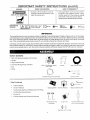
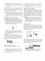
Carton
Contents
_
Main Unit pressure washer with wheels
Handle
_._.:
ili!_
• High Pressure Hose
ii_<:_i!i_::::
Chemical Pickup Hose and Filter
• Gun
•
_'
Main Unit pressure washer
with wheels
• Wand
_,'i/
Handle
High Pressure Hose
i!i
Gun and Wand
Chemical Pickup Hose and Filter
Bag Containing
Video Cassette
Owners'
Manual
Video Cassette
Nozzle Cleaning
Kit and Replacement
Handle Mounting
Hardware
Owners'
Manuai
Nozzie
Cteaning
Kit
O-Rings
Engine Oil
Rubber Isolator and Mounting
Hardware
Handle Mounting
Hardware
Enai<e Oil
Rep!acement O-Rings
Rubber isolator and
Mounting Hardware
Tools Required
for Assembly
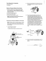
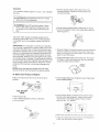
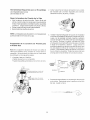
2. • Remove wood plank from the frame of the unit.
An adjustable wrench is required. Discard bolt
and board.
Adjustable wrench
1/2" Socket
Remove
Pressure
Washer
from
Carton
, Open box from the top. Locate and remove from
box, the parts box, which includes gun, handle,
wand,oil, knobs and J bolts. Next remove the parts
bag and the handle.
• Cut carton along dotted lines.
• Remove all carton inserts.
,, Roil unit through opening in carton.
3.
•
Note: The pressure hose and chemical hose are
located at the bottom of the box.
Preparing
the Pressure
Washer
for First Use
Note: Included with your pressure washer is a video
tape on how to prepare your unit for operation. It is
recommended you view this tape before performing
the next steps.
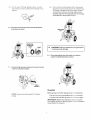
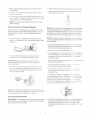
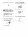
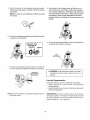
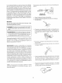
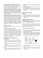
1. • insert handle onto frame.
Mount the rubber isolator to the frame. To
mount isolator place threaded end of bolt
through the washer. Next with washer on bolt
place threaded end of bolt through larger hole
in bottom of the rubber isolator. Place threaded
portion of isolator through the front hole
location where the wood plank was mounted on
the pressure washer. Next place Iockwasher
over threaded portion of bolt that has been
ptaced through the mounting hole in the pressure washer and use nut to tighten isolator to
the frame. Tighten nut with an adjustable
wrench. All isolator parts are supplied in parts
bag.
• Slide J bolts into frame.
• Tighten knobs turning in c!ockwise direction.
NUT
,.._!!
_
LOCKWASHER
PRESSU_i
_/
WASHER ,;
_;_"f
_ten knob
_-_
in clockwise
direction to threaded
o
/;'
ISOLATOR
end of d bo_,)
BOLT
(insert J boff here. Threaded
goes in bottom
end
hole)
,
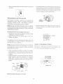
• Connect wand with nozz{e assembly to gun. To
tighten, turn knob in clockwise direction. Hand
tighten.
5. _ Cut tie wrap off of high pressure hose, Unwind
high pressure hose to attach the threaded end to
_e
gURo
8. _ Your units pump is shipped with a tempo_'a_
p_ug that must be repiaced with a breather cap,
This p_ug is located over the pump's oil port.
Unscrew and remove this plug. Remove the
breather cap from the bag attached to the plug
and instalJ it in the pump's oil port,
6. • Connect chemical hose to the chemical injector
hose barb on pump.
CHEMICAL
INJECTOR
HOSE
PUMP
BREATHER
CAP
,&
CAUTION" Failure to replace the plug will result
in serious pump damage.
9. • Place assembled
washer's handle
gun and wand on pressure
bracket as shown.
7. , Connect high pressure hose to the quick connect
outlet on pressure washer.
Uti
'
1;
CONNECT
Checklist
NOTE: Always keep hose away from engine
muffier,
Before going any further please review the following:
Be sure you have completed assembly instruction.
Double check aH fittings to be s{._rethey are tight.
IMPORTANT: Before any attempt to sta_ your pressure washer be sure to check engine oit (See Operation
under Engine Oil, page 9.}
I
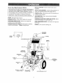
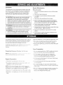
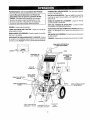
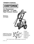
Know Your High Pressure
RECOIL STARTER- Used for starting the engine
manually.
Washer
Read this Owner's Manual and Safety Rules before
operation of your High Pressure Washer Compare
this illustration with our pressure washer to familiarize
yourself with the location of various controls and
adjustments. Save this manual for future reference.
PUMPENGINE
Develops
high pressure.
OIL FILL- Place where engine
oil is poured.
SPRAY GUN ASSEMBLY- Controls the application of
water onto cleaning surface with trigger device.
PUMP OIL FILL- Port where pump oit is poured and
breather cap is located.
GAS TANK/CAP- Cap is removed and unleaded
gasoline is poured.
CHEMICAL INJECTION TUBE AND FILTER- Mixes
water and detergent in outlet water flow.
PRESSURE REGULATORAllows you to adjust the
pressure of the outlet stream.
HIGH PRESSURE OUTLET- Connection for high pressure hose.
ENGINE RUN/STOP SWITCH- Sets engine in starting
mode for recoil starter -- Stops running engine.
CHOKE- Lever used for starting unit.
GUN WAND
)./_IASSEMBLY
HANDLE
HiGH PRESSURE HOSE
,\
ON/OFF
SWITCH
GAS
PRESSURE
REGULATOR
BREATHER
CAP
MUFFLER
PUMP OIL
PORT
CHEMICAL
ADJUSTMENT
KNOB
ENGINE O_L
FILL
PUMP
CHEMICAL _NJECTOR
TUBE & F_LTER
WATER INLET
CONNECTION
HiGH PRESSURE OUTLET
i
,Ik Warning: Read Owner's Manual. Do not attempt I
to operate equipment
until you have read Owners[
Matruua_cJOrnSafety, Operation,
and Maintenance
I
Note: Included with your unit is a video cassette that
demonstrates how to operate your pressure washer.
tf you have a video cassette recorder you should
view the video before operation,
,& Warning: Never adjust spray pattern when spraying. Never put hands in front of spray nozzle to
adjust spray pattern because you could be
injured.
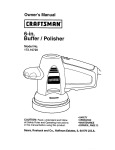
Stopping
Your Pressure
Adding
Before running the high pressure washer, check the
pump oil level by viewing the sight gtass on the side
of the pump, When properly filled, the oil will be at
the half way point marked by the two triangles. Your
pressure washer pump is shipped with oil, Add oil
only if oil level is lower than the half way point on the
sight glass. Do not overfill, Use 30 weight nondete;gent oil if necessary.
,& CAUTION: Do Not use engine oil that has been
[
shipped with your unit in your pump, Engine oil
I
is detergent and your pump uses a non-detergent [
oil. Detergent oil can cause damage to your pump,j
Washer
Engine
A CAUTION: Do not run pump without the water
supply connected
and turned on. Failure to do so
will result in pump damage.
To turn pressure washer
to the stop position,
Pump Oi[
off place the on/stop
switch
Oil
Your unit has been shipped without
oil in the engine.
A bottle of SAE 30 weight oil is included in the carton.
Remove oil plug located on the side of engine. Using a
funnel fill engine crankcase up to the last thread in the
oil port. Pour slowly. Oil reading will be inaccurate
on
unlevet ground.
Simply shutting OFF engine wig not release
pressure in the system.
Squeeze the trigger on the
spray gun for about 3 seconds to relieve pressure_
Spray stream wi!I decrease in length.
iMPORTANT:
This unit is equipped with a therma;
relief valve, if unit is allowed to run for severaI m;n -_Jtes without pressing the trigger on the spray gun,
several drops of water may be released through this
valve to cool the unit. The heated water will be pb_rged
from the bottom of the pump.
BEFORE
STARTING
THE
ENGINE
To operate the engine you wilt need to do the following,
A CAUTION: Always check engine oil levei before
every staR. Running engine !ow of oil or out of oil
couId result in serious damage.
A CAUTION: Always check pump oil Ievei before
_, every start, Running pump low on oil couId ,_-esu!t
in pump damage.
"
NOTE_ When adding oil to the engine crankcase;
use
a high quality detergent
oil classified
"For Service SF,
SG, SH rated SAE 30 weight. Use no special additives, Select the oiFs viscosity grade according
to
you expected operating temperatures.
SAE
Vi.'_eesity
Grades
Air cooled engines run hotter than automotive
engines.
The use of multi-viscosity
oil such as (10W-30, etc.) in
ambient temperatures
above 40°F (4°C) will result in
higher than normai oil consumption.
If multFviscosity
o]i is used, check the oi_ level more frequentIy
to
prevent any posssible engine damage due to lack or
lubrication.
Use of SAE30 oil below 40°F (4°C) will result in hard
starting and possible engine damage dL_e to inadequate _ubrication.
Gasoline
Connect garden hose to the water inlet on the
pressure washer. Tighten by turning water intet
counterclockwise.
Your pressure washer engine is 4 cycle. Use unteaded
fuel only.
CAUTION: Do not overfill the fuel tank. Always
allow room for fuel expansion.
WARNING: Never fitl fuel tank indoors. Never
fill fuet tank when engine is running or hot, Do
not smoke or have open flame when filting fuel
tank.
Connect high pressure hose to discharge on pump.
Connect the garden hose to the water spout and turn
water supply on.
Use clean, fresh, regutar unleaded gasoline with a
minimum of 85 octane. Do not mix oil with gasoline.
If unleaded fue_ is not availaMe, _eaded fuel may be
used.
#! f! I , ; _,,
iMPORTANT:
It is important to prevent gum deposits
from forming in essentia! fuel system parts such as the
carburetor, fuel filter hose or tank during storage. Also,
experience indicates that alcohol-blended
fuels (called
gasohoi or using ethanol or methanol) can attract moisture which leads to separation
and formation of acids
during storage. Acidic gas can damage the fuel system
of an engine while in storage. To avoid engine problems,
the fuel system should be emptied before storage of 30
days or longer. Never use engine or carburetor cleaner
products in the fuel tank or permanent damage may
occur,
Squeeze
pressure
spew out
easier to
trigger on pressure washer wand to relieve air
caused by turning on the water. Water witI
of the gun in a thin stream. This will make it
start the engine.
® Engage the safety latch on the spray gun. This locks
the trigger in place and keeps you from accidentally
spraying a high pressure stream.
AFETY
NOTE: Never start pressure washer with out water
source turned on and connected to pressure washer.
To Start
Your Pressure
Make sure fuel shutoff
position.
ATCH
Washer
o On the engine there is a choke!run lever. Place lever
to the choke position.
valve is turned to the open
OFF
__-_
_............
-- _................
z_:t
FUEL SHUTOFF
VALVE
Remove gas cap
® Add unleaded gasoline,
Do not overfill.
.,_/X:.iii_-i:
-_
"_ ...........
J
- '_)',_
On the engine there is a throttle control tever. Place
throttte to the rabbit position.
Always start engine
with throttfe in the rabbit position. Place on/stop
switch to the "on" postion.
slowly, to fuel tank.
ON
Make st_re fuel shut off valve is to the ope_ positio_.
Grasp the starter grip aad pull siow_y _ntit resistance
is felt_ then pull firmly to start engine.
10
Whenenginestarts,graduallymovechokeleverto
RUNposition.
}fenginedoesnotstartafter5 pu_ls,
piacechoke
backtorunposition.
Prepare
the soapichemica_
as required
by your job.
Insert soapichemicai
line into your container
chemicals not inc!uded).
(soap/
For hot engine starts make sure choke/run }ever is in
the run position, Make sure fue_ shut off valve is open
and throttie is in the Rabitt position.
NOTE: If any leaks are present shut unit down and
tighten fittings.
How
To Use Yeur
Pressure
Washer
NOT_; The first step involves applying an appropriate
soap/chemical
solution to penetrate and loosen grime.
The soap/chemica!
is appIied at iow pressure to avoid
splashing, over spray and waste. Leave the solution
on surface for 3 to 5 minutes to atiow solution to work.
On the end of your spray gun is a nozzle that you can
twist from side to side, With the adjustable nozzle you
can adjust the nozzie to either high pressure or Iow
pressure.
NOTE: The second step involves cleaning the surface
you have prepared with the pressure washer and then
rinsing it clean.
Turn the nozzle in a counter clockwise direction to
achieve low pressure. Turn nozzie clockwise for high
pressure.
Turn the adjustable nozzie counter c;ockwise
to low
pressure mode. Soap/chemicais
cannot be applied
with nozzle in high pressure position.
o Review the use of the adjustable r;oxz e.
o Connect garden hose to water infer (see "To Start "_,<our
Pressure Washer"), check that high p_{:-ss_.._re
hose is
connected
to spray gun and pump (s.i _ Assembly},
and start engine.
For most effective cleaning, keep spray nozzie
between 8 and 24 inches of cleaning sudaceo
o AppIy soap/chemicals
to dry surfac
bottom and working up.
iMPORTANT:
If you get spray nozzle too close,
especially on high pressure, you may damage the
cleaning su.dace.
o Al!ow the soap/chemicals
minutes before washing
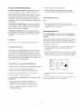
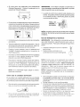
The pressure control knob is located on the pump.
You can increase the pressure by turning the knob
ciockw_se or decrease the pressure by turning the
knob counterclockwise.
/ rIq
_08
\ i
: .j
...,,
Your pressure washer is equipped with a (;isemicaI
injector adjustment
knob. With the k_u._b_uily opened
you will get maximum chemical draw. With knob fui_y
ciosedyouwiilgetnocbernicaidraw.
r knob_n
counter clockwise direction to achieve _(re chemica_
draw and clockwise for less chemicai d_"_w.
_,', ", /
x%
to soak i_ b : :,,een 3-5
and rinsing?;.
For cleaning, start at iower portion (::i }:_ to be
washed and work upward_ using !o;:
::.en over.iapping strokes.
::
'/_ _-._,.,_
.........
._\
'.,
'-,
,.
.'.string from the
, ,
/
NOTE; The maximum
pressure for the unit is set at its
maximum setting at the factory. Do not attempt Io adjust
the pressure higher than this factory setting.
//
;/i/
t_siasg Soaps/Chemicals
After using the p_essure washer, it is recommended
the pump, chemical iniector and chemical !ire be
flushed with clear wate._: To do so. simply place
chemical injector hose in water arsd siphon for I to 2
minutes.
IMPORTANT; Use soaps and chemicals that are designed
specifically for use with pressure washers. To apply soap/
chemicals follow these steps:
11
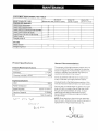
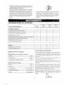
ON SIB_L{T'__
MAINTENANCE
PRESSURE
Every 25
Before each use Ihours oryearly
TASK
Even 50
hours oryeady
Ihours oryeady
WASHER
'C'heck!cIean infet"screen,
x
Check high pressure hose.
'Check soap andchemical hose andfilte_ChEck guriand wand for tea_'s.
Purge pump of air a5_ co ntamina nts
-CheSk pump oii
Chang_ pump oil
x
ENGINE
Check oil levet
x
x
x
x
x
x
Change engine oil
Product
Pressure
Specifications
Washer
General
2500
Flow Rate
CIeaning
The warranty of the high pressure washer does not
cover items that have been subjected to operator
abuse or negligence. To receive full value from the
warranty, operator must maintain high pressure
washer as instructed in this manual.
Specifications
Pressure
2.7 GPM
Units (psi x GPM)
Recommendations
6750
Some adjustments wil! need to be made periodocaIIy to maintain your high pressure washer,
Engine Specifications
RPM
Rated Horsepower
Spark Plug Gap
Gasoline
Oil
All adjustments
manual should
3600
Capacity
6.5
0.030"
in the Maintenance
section of this
be made at least once each season.
Once a year you should clean or replace the spark
plug and clean or replace the air filter and check
the gun and wand assembly for wear. A clean
spark plug and clean air filter assure proper
fuel-air mixture and help your engine run better
and last longer,
(0.76mm)
3 Quarts
SAE 30 weight
NOTE: Over time the o-rings in the gun assembly
become worn. Attached to your owners manuat is a
reptacememt
o-ring and split backup ring,
12
Pressure
Washer
Maintenance
Pull the trigger on the gun and hold.
Check and C_ean inlet Screen: Examine inlet screen
on pump inlet fitting, Clean if clogged replace if torn,
When the water supply is steady and constant,
diser_gage trigger and refasten the wand extension.
Chock High Pressure Hose: High pressure hose can
devetop _eaks from wear, kinking, and abuse. _nspect
hose each time before use. Check for cuts, _eaks,
abrasionsor
bulging of cover, damage or movement of
couplings, if any of these conditions exist, replace hose
immediately.
Chock Chemical/Soap
soap hose and clean if
on pump fitting. Check
filter or hose if either is
Maintenance
OH
OH level should be checked prior to each use
or at least every 5 hours of operation, To check oil see
Adding Engine Off on page 9.
Hose: Examine the chemical/
clogged. Hose should fit tightly
for leaks and tears. Replace
damaged.
Chock Gun and Wand: Examine hose connection
to
gun making sure it is secure. Test trigger by pressing
and making sure it springs back into place when you
re!ease it.
Pump
Engine
Changing
it
Engine
Oil
For a new engine, change oil after the first 5 hours of
operation. Thereafter, change oil after every 50 hours of
operation.
Change the oit while the engine is stitl warm. The oil will
ftow freety and carry away more impurities. Make sure
the engine is level when filling, checking, or changing oil.
OH
Pump oit level should be checked before each use.
Change the oil as follows:
Changing
Pump
,, To keep dirt, grass, etc., out of the engine, clean the
area around the drain plug and oil plug before
removing it.
Oi!
Oil shoutd be changed after the first 10 hours of operation. Subsequent
changes after each 50 hours of operation. To drain oil, simply remove oil plug with a adjustable wrench. The oii plug is located at the bottom of the
pump. Dispose of used oit. Properly remove pump oil filI
plug. Add 30 weight non-detergent
oil Flit until oil level is
at the mid point on the sight gIass.
Remove the oi! drain p_g and oil plug, Tilt the engine
slightly towards the oil drain to obtain better drainage.
Be sure to af_ew ampie time for complete drainage.
1,11,
Purge
Pump
of Air and Contaminants
W?;I
To remove
the air from
the pump,
follow
these
i/
%
steps:
Set up the pressure washer as described in
Assembly section and connect the water supply,
Remove the wand extension from the spray gun,
Reinstall the drain plug. Make sure it is tightened
securely.
Pull the trigger on the gun and hold.
To remove the contaminants
these steps:
from
o Fill the crankcase with new oil of the proper type, up
to the threads in the oi! port, Pour stowiy,
the pump, follow
Set up the pressure washer as described in
ASSEMBLY section, connect the water supply.
Remove the wand extension from the spray gun.
Start the engine according
OPERA TtON section.
to instructions
in the
13
• Reinstal! the oil fill cap or plug and tighten securely.
Service
Do not clean engine with a forceful spray of water
because water could contaminate fuel system. With
a brush or cloth clean finger guard after every use to
prevent engine damage caused by overheating.
RNGER
GUARD
Air Cleaner
To service pre-cleaner, wash in liquid detergent and
water. Allow to dry thoroughly before using. Do not oil
pre-cleaner. Replace if very dirty or damaged.
Before running engine, clean muffler area to remove all
combustible debris.
NOTE: Do not use petroleum solvents, e.g., kerosene,
which wil! cause the cartridge to deteriorate.
Do not use
pressurized
air to clean cartridge. Pressurized air can
damage the cartridge.
To service air cleaner follow these steps:
I. Unscrew cover screws. Remove cover and air cleaner
assembly.
2. Remove cartiridge from cover, then retainer
(if equipped) and pre-cleaner.
NOTE: Do not use petroleum solvents, e.g., kerosene,
which will cause the cartridge to deteriorate.
Do not use
pressurized
airto clean cartridge. Pressurized air can
damage the cartiridge.
Clean and Replace
Spark
Plug
Change the spark plug every 100 hours of operation or
once each year, whichever comes first. This will help
your engine to start easier and run better.
3. Reassemble pre-cfeaner or retainer (if equipped.)
Place in cover with pre-cleaner mesh side toward
cartridge. Place cartridge in retainer in cover.
4. Push cover and air cleaner assembly squarely onto
base (tabs must be in slots, if equipped) and hold
firmly. Tighten cover screws securely.
RES1STOR
Keep engine
and parts
clean!
14
Carburetor
Nozzle
Maintenance
The carburetor of your high pressure washer is pre,*set
at the factory, The carburetor should not be tampered
with, _fyou pressure washer is used at an altitude in
excess of 5000 feet consult with your nearest Sears
Service Center regarding high altitude set changes.
Hi-Low
Lance:
I.
Shut off the pressure washer and turn off the water
suppty.
2. Disconnect spark plug wire.
3, Pull trigger on gun handle to relieve any water
pressure.
A CAUTION:
Engine speed was properly adjusted
at the factory and shoutd require no additional
adjustment.
Do not attempt to change engine
speed. If you believe the engine is running too fast
or too slow, take your pressure washer to a Sears
Authorized Service Center for repair and adjustment.
4, Disconnect the wand/lance from the gun,
5. Remove the high-pressure nozzle from the lance.
Remove any obstructions with the nozzle cleaning
tool provided and backflush with clean water.
6. Direct water supply into nozzle end to backflush
loosened particles for 30 seconds,
_WARNING:
High engine speeds are dangerous and
increase the risk of personal injury or damage to
equipment.
7. Reassemble the nozzle to the lance using teflon tape
to prevent leaks. Tighten securely.
8. Reconnect wand/lance to gun and turn on water
supply.
,_I,WARNING:
Low engine speeds impose a heavy
toad on the engine and when sufficient engine
power is not available could shorten engine life.
9. Start pressure washer and place wand/lance into
high pressure setting to test.
This pressure washer should be stored in such a way to
protect it from freezing.
Do not store this unit outdoors
or in an area where temperatures
wH! fal! below 32 ° R
This can cause extensive damage to this unit°
Add one teaspoon
o Repiace
Washes
for
T_p the unit on the end with the water
poi_!ting upward.
o Run pressure wass_er for fuif 5 min:_tes to al!ov_,_ f,._ei
stabilizer to enter the rue! system.
and disconnect
Set unit upright and pull starter handle on engine 4 to
6 times to circulate anti-freeze in pump until antifreeze is discharged from the pump.
the water supp!yo
pl_xg wire and remove
inlet fitting
Pou_ approximately
1/4 cup of nomtoxic R.V. antifreeze down the fitting where the water hose attaches
to the Dump.
NOTE: Whiie doing this procedure make sure wa, te,
supp!y is turned on and flowing to ,the unit. NEVER run
unit without water suppiy running th_rough pump,
the spark
Preparation
P{s!ithe recoil on the engine 4 to 6 times to discharge
_-_mainingwater in pump_
First add a f_ei stab;_izer _o the fuei tang..
Disconnect
plugo
the spark
Puii the trigger on the spay gun to release the
p_essL_rein the high pressure hose, Detach high
rsressure hose and garden hose from the unit.
Preparatio_
Next shut off engine
the spark plug, but do not connect
Be sure engine switch is in "OFF" position and spark
piug wire has been removed from spark plug.
Storag_:_
NOTE: If you do not piar_ i<; c_se yo,_ _ _._.i-_it
_:::_30 :.::_.,:sc _
more, unit shouid be prepared [or s_or_{_e.
Engine
hole.
piug wire.
P_mp
Pressure
the spark plug
Place rag over spark plug hole and pull the recoil a
few times to lubricate the combustion
chamber.
_f unit has to be stored under freezin£_} co_ditio_-_s a nontoxic R.V, anti-freeze
can be used to p_otec_ fro:_
freezing.
Preparing
of oil through
the spa_k
15
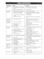
SYMPTOM
CAUSE
SOLUTION
Engine won't
start
1. Engine throttle is in "OFF" Position.
2. Choke lever has not been placed to
choke.
S_ide thro_te to "Rabbit" position.
2. Slide choke tever to choke position°
3. Pressure buildup
3. Depress trigger gun.
Won't Draw
Chemical
after initial use.
l. Nozzle not in chemical draw position.
2. Chemical screen is obstructed.
3. Chemical screen not working.
Pump running
normally but
pressure does
not achieve
rated values
4. Chemical
or stuck.
injector orifice obstructed
5. Chemical
injector closed.
1. Water supply
5. Open chemical
knob.
restricted.
t.
2. Nozzle is in low PSi position.
2.
3. Nozzle incorrect
3.
4.
5.
or worn.
4. Pump sucking air.
5. Nozzle blocked.
Fluctuating
Pressure
1. Place nozzle to low pressure.
2. Check chemical screen; clean if obstructed.
3. Make sure chemical screen is submerged in
chemical/water.
4. Check and clean.
1. Pump sucking air.
2.
3.
4.
5.
injector by turning adjustment
Check water supply and filter screen for.
blockage. Check hoses for btockage_ kinks,
leaks, etc.
Twist nozzle at end of wand clockwise the high
pressure poskion.
Check and replace.
Check that hoses and fittings are air-tight.
Clean nozzle.
t. Check that hoses and fittings are air tight. Purge air
from garden hose.
2. Clean. Check filter frequently.
3. Check and replace.
4. Check hose for kinks.
Garden hose inlet strainer clogged.
Worn Seals or Packing.
Inadequate water supply.
Fouled or dirty inlet or discharge
valves.
5. Check flow available to pump. Check for
excessive heat, 145° F or above.
6. Clean inlet and discharge valve assemblies.
Replace if damaged.
6. Leaky discharge
hose.
Pressure drops
after period of
normal use
I.
partially obstructed.
2.
Nozzle worn.
3. Pump Valves worn, dirty or stuck.
4. Worn pump piston packing.
Use nozzle cleaning kit to clear obstruction. (See
Nozzle Maintenance under Service Adjustment.)
2. Clean or replace.
3. Check and replace.
4. Check and replace.
Pump noisy
t,
Water too hot.
2. Pump sucking air.
3. Valves dirty or worn.
4. Worn bearings.
!. Reduce temperature below 63 ° C or 145 o F.
2. Check that hoses and fittings are air tight.
3. Check, clean or replace°
4. Check and replace if necessary.
Presence
I. High humidity.
2. Piston packing and oil seal worn.
of
water in oi_ (oi!
milky),
Water dripping
from pump
Nozzle clogged,
1. Change Qi!.
I 2. Check and replace oil seats_
1. Thermat relief functioning normal.
2. FiRings Loose.
3. O-rings of piston guide or retainer
1. Protecting pump, if not using pressure washer for
a long period of time. shutoff engine.
2. Tighten°
3. Check and replace.
4. Check and rep}ace_
worn,
4. Piston packing worn.
O _ Dripping
-.._
1.
1. Oi{ seai worn
2. Loose drain plug or worn drain plug
o-dng°
i. Check and replace
2. Tighten drain plug orreplaceO-ring.
16
Do not over torque.
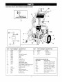
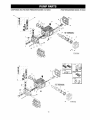
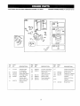
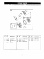
CRAFTSMAN
2500 PSI HIGH PRESSURE WASHER 919.762500
5
1
8
22__
@_23
1
(_----
24
21
18
KEY#
PART NUMBER
DESCRIPTION
KEY#
PART NUMBER
DESCRIPTION
1
2
3
4
5
6
7
8
9
lO
It
12
9OO
16498
16471
16396
16504
16371
16470
16503
16830
H100
16823
15111
16501
Handle
Knob
Gun
Tire Simi-Pnuematic
Foot Rubber
J Bolt
Frame
O_ring Kit
Chemical Hose
Lance Hi/Low
High Pressure Hose
Decal Front Craftsman
21
22
23
24
N03515
Ft I9
F078
F112
Nozzle
Hex Nut
Lock Washer
Fiat Washer
16727
PKI6642
F035
16829
F464
F064
Engine (Refer to Engine Breakdown
Bdggs #121432-01 t2-E1)
Decat Operation
Pump
High Pressure QC
Adapter* Garden Hose
Nut Pal 1/2"
Stew Hex HDC
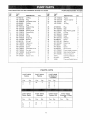
15
16
17
18
i9
20
PARTS NOT iLLUSTRATED
I7
MGP-762500
Owners Manual
F078
Lockwasher,
Fl19
Nut Hex 3t8" Engine to Frame
F066
SCrew 3/8" Engine to Frame
F107
Lockwasher-Pump
15167
Srew, Hex- Pump to Engine
F078
Lockwasher_
NCT00I
Nozzle Cleaning Kit
F039
QC Socket for HP Hose
17091
Nozzie 3 pack 0°, 25 °, 40 °
Spray Pattern
Engine to Frame
to Engine
Pump to Engine
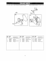
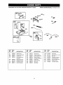
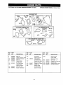
CRAFTSMAN
2500 PSI HIGH PRESSURE WASHER 919.762500
PUMP BREAKDOWN
t6
t0
14
11
t2 13
15
24
7O
40
i
28
73
36
38
C
/
F
{
D
C
t8
MODEL PK16642
ORAFTSMAN
2500PSiHIGHPRESSURE
REF,
NO.
PART
NO.
WASHER 9!9.762500
DESCRIPTION
QTY.
I
2
3
4
5
6
7
AR-960160
AR-1260t 62
AR-1269050
AR-880830
AR-62030t
AR-1780130
AR-t260130
O-Ring
P_ug
Complete valve
O-Ring
Plug
Support ring
Gasket
6
6
6
6
1
3
3
8
9
10
11
12
13
14
t5
16
17
AR-1780090
AR-1780010
AR-t266740
AR-1260790
ARq780550
ARq 780490
AR-880130
AR-I780050
AR-t780510
AR-1200430
Piston guide
Pump body
Cap
Circlip
Snapring
Bearing
Oil cap
Piston pin
O-Ring
Screw
3
I
1
t
!
1
t
3
1
6
18
19
AR-1789010
AR-1780040
Complete
Con rod
1
3
20
.2!
22
AR-1780060
AR-480480
AR-i260091
Guiding piston
O-Ring
Spacer disc
cover
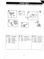
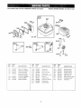
PUMP BREAKDOWN
_,
NO,
PART
NO.
23
24
25
27
AR-I780070
AR-1260100
AR-1260! I0
AR_740290
28
30
3I
32
33
36
37
38
40
41
42
44
67
68
69
70
7i
72
73
3
3
3
AR-880530
AR-!260460
AR-t780100
AR_770260
AR-1260440
AR-t780380
AR-138!550
AR-680570
AR-1321190
ARq321080
AR-48067!
AR-t80030
AR-820440
AR-1789200
AR-1380580
ARq780590
16747
AR-2973
16506
DESCRIPTION
QTY.
Piston
Piston washer
Nut
3
3
3
O-Ring
2
Plug
Seat
Rear Piston guide
O-Ring
Gasket
Head
Washer
Screw
Bearing
Snap ring
Seal
Screw
Grub screw
Pump head pre-ass,
Gas engine flange
Holiow shaft ¾"
Chemical tnjector
Unloader
Therma_ Relief Valve
PARTS KiTS
]
A=K1T 16739
Valves
B=KBT16746
Pistons
Pos.
3
4
Pos.
23
Qty.
6
6
i
F=KIT 16749
Beadngs
Pos.
Pos.
7
32
3
3
33
3
13
40
10
16
30
42
Qty.
!
t
3
1
G=KmT 16747
_njector Kit
Qbj.
I
I
Oil
Seals
for
C=KIT
16748
D Version
Pos
Qty.
3
D=K_T 18745
Water Seals
Qty.
i
Pos, Qt'y,
_
19
71
!
H=K_T 16744
Unloader O-Ring
Kit
Pos,
PKt6642
Qty,
2
3
3
3
3
1
8
8
1
1
1
4
1
1
1
!
I
I
1
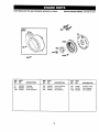
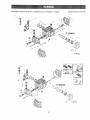
CRAFTSMAN
2500PS_ H_GH
PRESSURE WASHER 9I 9.762500
BRIGGS
ENGINE
MODEL
#12t 432-0! 12-Et
12
REF.
NO.
PART
NO.
DESCRIPTION
1
2
3
t 2
690045(P)
399269
692266
692549
Cylinder Assembly
Bushing
Seal-Oil
Gasket-Crankcase
15
69t 696
Ptug-Oii
REF.
NO,
PART
NO.
DESCRIPTION
REF.
NO.
PART
NO,
DESCRIPTION
17
18
20
2t
22
692510
690047
692550
692261
692551
Bearing-Bait
Cover_Crankcase
Seal-Oil
Cap-Oil Fil!
Screw-Hex.
306
307
529
1019
1058
692552
690345
692553
690035
273700
Shield-Cylinder
Screw_Hex.
Grommet
LabeiKit
Qwner_sManuai
2O
CRAFTSMAN
2500PSi
HiGH PRESSURE WASHER 919.762500
BRIGGS
ENGINE
MODEL
#121432-0112-E1
13,,
305A
63s_
305
_o22'-..._f
, RE£
NO.
5
7
tt
13
33
34
35
40
45
51
124
PART
NOo
DESCRIPTION
499922
692554
692600
691137
499642
499641
69 t 304
692194
690977
692555
692568
Head-Cylinder
Gasket-Cylinder
Tube-Breather
Screw*Hex.
Vatve-Exhaust
Valve=intake
SpdngWaive
Retainer-Valve
TappetWalve
Gasketqntake
Screw*Hex.
Head
REF.
NO.
PART
NO.
DESCRIPTION
155
189
692556
69t 295
Piate-Cy!inder
Head
Bali-Rocker
Arm
238
305
305A
691300
691 ! 08
692557
337
353
383
635
830
_
RER
NO.
PART
NO,
DESCRIPT!ON
868
692044
SeaFValve
Cap-Valve
Screw*Hex,
Screw-Hex.
978
1022
1023
1026
69t 892
691890
499924
692560
Gasket-Plate
Gasket-RockerCover
Cover-Rocker
Rod-Push
690965
692558
Plug-Spark
Nut-Hex.
1029
1034
691230
691343
Arm_Rocker
Guide-Push
19374
692186
692559
Wrench-Spark
Plug
Boot-Spark
Plug
Screw_Hex,
2!
Rod
CRAFTSMAN
2500 PSI HIGH PRESSURE WASHER 919.762500
BRIGGS
ENGINE
MODEL
#121432-0112-E1
17
24_
26
742
743_
RER
NO.
PART
NO,
DESCRIPTION
16
17
24
25
26
27
28
692561
692510
690974
499627
499631
691866
499423
Crankshaft
Bearing-Bali
Key-Flywheel
Piston Assembly
Ring Set
Lock-Piston Pin
PimPiston
RER
NO.
PART
NO,
DESCRIPTION
29
30
32
46
690124
692562
691664
692563
Rod-Connecting
Dipper-Connecting
Screw-Connecting
Gear-Cam
22
Rod
Rod
_
RER
NO.
PART
NO.
DESCRIPTION
146
219
220
741
742
743
690979
692418
691724
692565
692564
692566
Key-Timing
Gear-Governor
Washer-Thrust
Gear-Timing
Ring-Retaining
Gear-fdler
CRAFTSMAN
2500
PSi HIGH PRESSURE WASHER 9t9.762500
BRIG GS ENGINE
MODEL
#12!432-0112-E1
1
124
@
,%
@ _4
634A
137_
t!o@
REF_, PART
i NO.
NO_
DESCRIPTION
REF_ PART
NO.
NO.
DESCR!PT1ON
REFo
NO.
PART
NO.
DESCR_P3"tON
s.............
51
692555
95
98
104
108
110
691636
398185
691242
692567
1!I
690572
Gasket-Intake
(2 Required)
Screw=Slotted
Screw-ldle Speed
Pin-Float Hinge
Vatve_Choke
Washer-Sea;
(Sotd in Kit Only)
Spring-Friction
(Choke)
1t7
122
127
690048
690043
130
I3I
133
t34
691181
699024
398187
398188
Jet-Main (Standard)
Spacer-Carburetor
Plug-Welch
(Sotd in Kit Oniy)
Valve-Throttle
ShaffoThrottte
Float-Carburetor
Valve-Needle
137
!41
163
699023
691887
186
692317
634
634A
975
23
493640
Gasket-Float Bowl
(Sold in Kit Only)
Shaft-Choke
Gasket-Air Cleaner
Connector-Hose
Washer
(Sold in Kit Only)
Washer
(Soid in Kit Oniy)
Bowl-Float
CRAFTSMAN
2500 PSi HIGH PRESSURE WASH ER 919.762500
!
BRIGGS
ENGINE
MODEL
#121432-0112-E1
562
211
281
188
"i
81_N6 s....
356A
4
RER
NO,
PART
NO,
75
98A
188
202
495659
493280
690877
692569
209
211
222
227
692569
691798
692572
692573
1
DESCRIPTION
RER
NO.
PART
NO.
DESCRIPTION
Washer Set
Screw-ldle Speed
Screw-Hex.
Link-Mechanical
Governor
Spring-Governor
Spring-Governor
Bracket-Control
Lever-Governor
232
265
267
281
333
334
347
354
356
692570
691024
690804
692574
692605
691061
692599
692575
692602
Spring-Link
Clamp-Casing
Screw-Slotted Hex.
Panel-Contro!
Armature-Magneto
Screw-Hex.
Switch-Rocker
Nut-Lock
Wire-Stop
24
347
RER
NO.
PART
NO.
DESCRIPTION
356A
562
592
615
616
663
843
851
692603
691112
691251
692576
692547
692577
692578
493880
Wire-Stop
Bolt-Governor Level
Nut_Hex.
Retainer-Governor
Crank-Governor
Screw-Slotted Hex.
Sleeve-Lever
Terminal-Cable
CRAFTSMAN
2500PS!HiGHPRESSURE
WASHER
919.762500
8RiGGS
ENG{NE
MODEL
#121432-0112-Et
957
642
534_
967
535
346
RE_
NO,
PART
NO.
161
163
176
t 87
692579
691887
692 t27
298049
t87A
298
300
692601
690453
692580
DESCRIPTION
Base-Air CIeaner
Gasket-Air Cleaner
Screw-Shoulder
Line-Fue} (Cut to
Required Length)
Line_Fue_ (Motded)
Locknut_Muffler
Muff_e_---Exhaust
RE_.
NOo
PART
NO.
DESCRIPTtON
346
346A
373
526
534
535
601
642
819
832
690661
692581
692582
691127
692583
691710
692201
692584
692598
692584
Screw-Hex.
Screw*Hex.
Nut-Tinnerman
Screw-Hex,
Screw-S_otted Hex.
Filter-Air
C_amp-Hose
Cover-Air C!eaner
Screw-Hex.
Guard-Muffler
25
REEF, PART
NO,
NO°
DESCR_PT[O_
863
863A
864
957
958
967
97I
972
Bracket-Muffler
Bracket_Muffter
Adapter_Muffier
Cap-FueI Tank
Valve-Shutoff
Fi_ter_Air (Pre-FiIteO
Screw-Shoulder
Tank_Fuei
692595
692596
692548
69I 654
692586
69t 706
69I t06
692587
CRAFTSMAN
2500 PSi HIGH PRESSURE WASHER 919.762500
BRIGGS
ENGINE
MODEL
#121432-0112-E1
23
1005
332 (_
188A _
305 _'
RER
NO.
PART
NO.
..............
23
65
188A
692588
692608
692590
RER
NO.
DESCRIPTION
,
Flywheel
Screw-Hex.
Screw-Shoulder
,,,,
PART
NO.
..............
304
305
332
,...................
692589
691108
690662
RER
NO.
DESCRIPTION
Housing-Blower
Screw-Hex.
Nut-Ffywheel
26
,,,,, L,
PART
NO.
DESCRIPTION
,.................................
363
455
1005
19069
692591
692592
Flywheel Puller
Cup-Flywheel
Fan-Flywheel
CRAFTSMAN
RER
NO.
PART
NO.
55
691422
56
58
498144
692593
59
692594
2500 PS! HIGH PRESSURE WASHER 919,762500
BRIGGS
ENGINE
MODEL
#121432-0112-E1
REF,
PART
REF.
PART
DESCRIPTION
NO,
NO,
DESCRIPTION
NO.
NO.
DESCRIPTION
HousingoRewind
Starter
Puliey-Starzer
Rope_Starter (Cut To
Suit)
Insert-Grip
60
60A
65A
373A
393152
691930
690837
690800
Gdp_Starter Rope
Grip-Starter Rope
Screw-Hex.
Nut*Hex.
459
608
623
689
692260
497830
691696
69! 855
PawFRatchet
Sta_Se_'_Rewind
Screw-Shoulder
Spring-Friction
456
692299
RetaineFSpring
27
CRAFTSMAN
2500 PSi HIGH PRESSURE WASHER 919,762500
BRIGGS
ENGINE
MODEL
#121432-0t12-E1
358 GASKET SET
1022
868_
1033 VALVE OVERHAUL
121 CARBURETOR
KIT
_'_-J_
70
KIT
t
634 @.
534A@
13
11o@
127_
977 CARBURETOR
110 _
137_
REFo PART
NO.
NO.
3
7
12
20
5t
692266
692554
692549
692550
692555
104
1t0
691242
121
122
690032
690043
DESCRIPTION
Seal-Oil
Gasket-Cylinder Head
Gasket-Crankcase
Sea!-Oil
Gasket-Intake
(2 Required)
Pin-Float Hinge
Washer-Seat
(Sold in Kit Only)
Carburetor Kit
Spacer-Carburetor
RER
NO.
127
134
398188
137
163
358
634
_
634 @
PART
NO,
691887
690031
GASKET SET
16_
634A@
DESCRIPTION
Plug-Welch
(Sold in Kit Only)
Valve-Needle
(includes Seat)
Gasket-Float Bowl
(Sold in Kit Only)
Gasket-Air Cleaner
Gasket Set
Washer-Shaft
(Throttle Shaft)
(Sold in Kit Only)
28
RER
NO.
PART
NO.
DESCRIPTION
692044
690033
691892
691890
690034
Washer-Shaft
Choke Shaft
(Sold in Kit OnLy)
Seat-Valve
Gasket Set-Carburetor
Gasket-Plate
Gasket-Rocker Cover
Kit-Valve Overhaul
634A
868
977
978
1022
1033
Briggs & Stratton Corporation (B&S), the California Air Resources Board (GARB)
and the United States Environmental Protection Agency (U.S. EPA)
Emission Control System Warranty Statement (Owner's Defect Warranty Rights and Obligations)
In the interestofthe environment,B&S enginesthatmeet stdctemisTO CERTIFIED ENGINES PURCHASED iN CALiFORNiA IN 1995
sionrequirementsare labeled,'qhis engine conformsto 1995-1998
AND THEREAFTER, WHICH ARE USED iN CALIFORNIA, AND
California emission regulations for ULGE engines and U.S. EPA
TO CERTIFIED MODEL YEAR 1997 AND LATER ENGINES
Phase I ragutationsforsmatl non-road engines."
WHICH ARE PURCHASED AND USED ELSEWHERE tN THE
EMISSION CONTROL WARRANTY COVERAGE IS APPLICABLE
UNITED STATES.
California and United States Emission Control Defects Warranty Statement
GARB, U.S. EPA and B&S are pleased to explain the Emission
there has been no abuse, neglect or improper maintenance of your
Control SystemWarranty on your 1996 and later utility or lawn and
ULGE engine.
garden equipment (ULGE) engine. In California, new ULGE engines
Your emission control systemincludespartssuch as the carburetor,
produced on or after August 1, 1995 must be designed, built and
air cleaner, ignition system, muffler and catalytic converter. Also
equipped to meet the State's stringent anti-smog standards., Elseincluded may be connectors and other emission related assemblies.
where in the United States, new non-road, spark-ignition engines
Where a warrantable condition exists, B&S will repair your ULGE
certified for model year I997 and later, must meet similar standards
engine at no cost to you including diagnosis, parts and labor.
set forth by the U.S. EPA. B&S must warrant the emission control
system on your engine for the periods of time listed below, provided
Briggs & Stratton Emission Control Defects Warranty Coverage
ULGE engines are warranted relative to emission control parts
below.lfanycoveredpartonyourengineisdefective,
the part wiltbe
defects for a period ol two years, subject to provisionsset forth
repaired or replaced by B&S.
Owner's Warranty Responsibilities
As the ULGE engine owner, you are responsible for the performance
You are responsible for presentingyour ULGE engine to an Authoof the required maintenance listed in your Operator/Owner Manual
rized B&S Service Dealer as soon as a problem exists. The undisB&S recommends that you retain ait your receipts covering mainteputed warranty repairs should be completed ina reasonable amount
nance on your ULGE engine, but B&S cannot deny warranty solely
of time, not to exceed 30 days.
for the lack of receipts or for your failure to ensure the performance of
If you have any questions regarding your warranty rights and
a}l scheduled maintenance.
responsibilities, you should contact a B&S Service Representative
at 1-4t4-259-5262.
As the ULGE engine owner, you shoutd however be aware that B&S
may deny you warranty coverage if your ULGE engine or a part has
The emission warranty is a defects warranty. Defects are judgedon
failed due to abuse, neglect, improper maintenance or unapproved
normal engine performance.The warranty isnot related to an in-use
modifications.
emission test.
Bdggs & Stratton Emission Control Defects Warranty Provisions
The following are specific provisionsrelative toyourEmission Control Defects Warranty Coverage. it isin addition to the B&S engine warranty
for non=regulated engines found in the Operator/Owner Manual.
t. Warranted Parts
3. No Charge
Coverage under this warranty extends only to the parts listed
Repair or replacement of any Warranted Part will be performed
below (the emission control systems parts) to the extent these
at no charge to the owner, including diagnostic labor which leads
to the determination that a Warranted Part is defective, if the
parts were present on the engine purchased,
diagnostic work is performed at an Authorized B&S Service
a_ Fuel Metering System
Dealer. For emissions warranty service contact your nearest
•
Cold start enrichment system (serf choke)
Authorized B&S Service Dealer as Iisted in the "Yellow Pages_
Carburetor and intemat parts
under "Engines, Gasoline," "Gasoline Engines," "Lawn
Mowers," or similar category.
•
Fuel Pump
4.
Claims and Coverage Exclusions
b. Air Induction System
Warranty
claims shall be filed in accordance with the provisions
°
Air cleaner
of the B&S Engine Warranty Policy. Warranty coverage shall be
°
intake manifold
excluded for failures of Warranted Parts which are not odginat
B&S parts or because of abuse, neglect or improper maintec. Ignition System
nance as set forth in the B&S Engine Warranty Poticy. B&S is not
•
Spark plug(s)
liable to cover failures of Warranted Parts caused by the use of
°
Magneto ignition system
add-on, non-originaL or modified parts.
d. Catalyst System
5. Maintenance
Catalytic converter
Any Warranted Part which is not scheduled for replacement as
required maintenance or which is scheduled only for regular
•
Exhaust manifold
inspectionto the effect of "repair or replace as necessary" shalt
,
Air injectionsystem or pulse valve
be warranted as to defects for the warranty period. Any
e. Miscellaneous Items Used in Above Systems
Warranted Part which is scheduled for replacement as required
maintenance shall be warranted as to defects onty for the period
•
Vacuum, temperature, position,time sensitive valves
of time up to the first scheduled replacement for that part. Any
and switches
replacement part that is equivalent inperformance and durability
® Connectors and assemblies
may be used in the performance of any maintenance or repairs.
2. Length of Coverage
The owner is responsible for the performance of all required
maintenance, as defined in the B&S Operator/Owner Manual.
B&S warrants to the initial owner and each subsequent purchaser
that the Warranted Parts shall be free from defects in materials
6. Consequential Coverage
and workmanship which caused the failure of the Warranted
Coverage hereunder shall extend to the failure of any engine
Parts for a period of two years from the date the engine is delivcomponents caused by the failure of any Warranted Part still
ered to a retail purchaser.
under warranty.
29
Briggs & Stratton welcomes warranty repair and apologizes
to you for being inconvenienced.
Any Authorized Service
DeaJer may perform warranty repairs. Most warranty repairs
are handled routinely, but sometimes requests for warranty
service may not be appropriate. For example, warranty would
not apply if engine damage occurred because of misuse, lack
of routine maintenance, shipping, handling, warehousing or
improper installation. Similarly, warranty is void if the serial
number of the engine has been removed or the engine has
been altered or modified.
4.
5.
Repair or adjustment of associated parts or assemblies
such as cJutches, transmissions, remote controls, etc.,
which are not manufactured by Briggs & Stratton.
6. Damage or wear to parts caused by dirt, which entered
_he engine because of improper air cleaner maintenance,
re-assembly, or use of a nomodginal air cleaner etement
or cartridge. (At recommended intervals, clean and re_oit
the Oii-Foam® element or the foam pre-c}eaner, and
replace the cartridge.) Read "Owner's Manual."
7. Parts damaged by overspeeding, or overheating caused
by grass, debris, or dirt, which plugs or cIogs the cooting
fins, or flywheel area, or damage caused by operating the
engine in a confined area without sufficient ventilation.
(Clean fins on the cylinder, cylinder head and flywheel at
recommended intervals.) Read "Owner's Manual."
if a customer differs with the decision of the Service-Denier, an
investigation wilt be made to determine whether the warranty
appties. Ask the Service Dealer to submit a_]supporting facts to
his Distributor or the Factory for review. If the Distributor or the
Factory decides that the c_aim is justified, the customer will be
fulh/reimbursed for those items that are defective. To avoid
misunderstanding which might occur between the customer
and the Dealer, _isted below are some of the causes of engine
failure that the warranty does not cover.
tmproper maintenance:
8.
The life d an engine depends upon the conditions under
which it operates, and the care it receives. Some applications,
such as tillers, pumps and rotary mowers, are very often used
in dusty or dirty conditions, which can cause what appears to
be premature wear. Such wear; when caused by dirt, dust_
spark plug cleaning grit_ or other abrasive matedal that has
entered the engine because of improper maintenance, is not
covered by warranty.
9.
PROBLEMS CAUSED BY PARTS THAT
ORIGINAL BRfGGS & STRATTON PARTS.
ARE
NOT
2,
Equipment controls or installations that prevent starting,
cause unsatisfactory' engine performance, or shorten
engine life. (Contact equipment manufacturer.)
3_
Leaking carburetors, dogged fuel pipes, sticking valves,
or other damage, caused by using contaminated or sta_e
fuet. (Use clean, fresh, lead-free gasoline and Briggs &
Stratton gasoline stabilizer, Part No. 5041 .)
Engine or equipment parts broken by excessive vibration
caused by a loose engir',e mounting, toose cutter blades,
unbalanced Mades or Ioose or unbala_ced impetlers,
improper attachment of equipment to er_gine crankshML
overspeeding or other abuse in operation.
A bent or broken crankshafL caused by striking a solid
object with the cutter b!ade ot a rotary lawn mower, or
excessive v-belt tightness.
t0. Routine tune-up or adjustment of the engine.
1I. Engine or engine component faiiure, i.e, combustion
chamber, valves, vatve seats, valve g_Jides, or burned
starter motor windings, caused by the use of alternate
fuels such as, liquified petroleum, natu_at gas, a_tered
gasolines, etc.
This warranty covers engine related defective material
and]or workmanship
_
and not re_21acement or refund
of the equipment to which the engine may be mounted.
Not does the warranty extend to repairs
required
because of:
1,
Parts which are scored or broken because an engine was
operated with insufficient or contaminated lubricating oil,
or an incorrect grade of lubricating oil (check oil level daily
or after every 8 hours of operation. Refi}l when necessary
and change at recommended intervals.) Read "Owner's
Manual,"
3O
For the
repair
or replacement
parts
Call 7 am - 7 pro, 7 days
you need
a week
II -800m366-PART
(1 =800-366-7278)
For
in-home
major
Ca]_ 24 hours
brand
repair
a day, 7 days
service
a week
1 -800-4-REPAIR
{1 °800-473=7247)
Fer the
Sears
Parts
and
location
Repair
Ca_! 24 hours
of a
OeHter
a day, 7 days
1 =800-488=i
For
information
MaintenaRce
about
in your
222
Agreement
A__I
-- ---- --=,,--i
a Sears
or to inquire
Agreement
call £ am o 5 pro, Monday-Saturday
1 °800_827=6655
A_,qedca's Repair
Sea_s,
Ro÷b_ck
and
Specialists
Coo, Hoffman
L
a week
on purchasing
an e×isting
area
Estates,
_L 60179
U.SoA.
MANUAL
DEL
MAN
®
Lavadora de Alta Presi6n
6.5 Caballos de Fuerza
PSI 2.7 GPM
Modelo No.
919.762500
ADVERTENCIA:
Leer este
manual y observar
todas ias
Precauciones
de Seguridad
e
Instrucciones
de Operacibn
antes de usar este equipo,
LINEA
DE AYUDA AL
CL|ENTE
PARA
A LA
MAQUINA
LAVADORA
A PRESlON
1-800-245-5873
• Seguridad
• Ensamblaje
• Operaci6n
...................
_;Y• Mantenimiento
,.
_-----. iL:
• Lista de Partes
• Espa_ol
/
Sears,
16500
MGP-762500A
4/15t98
Roebuck
and
Co.,
Hoffman
Estates,
|L 60179
U.S.A.
TABLA DE CONTEN|DO$
Garanfia ....................................................
Operaci6n
Servicio
y Regutaciones
...........................
35-37
Afmacenamiento
..........................................
37-39
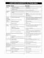
Guia para DiagnSstico
........ _....................................
40-44
Partes ..................................................
42-44
C6mo Ordenar
Pautas de Seguridaci
Ensamblaje
34
Mantenimiento
..........................
....................................
GARANT_A
LIMIITADA
......................................
de Problemas
Repuestos
DE UN ANO PARA LAVAOORAS
DE ALTA PRESJ6N
GARANT_A
a Presi6n se usa papa propSsitos
comerciales
per 90 d[as a partir de la fecha de compra,
LJP_TADA
DE UN ANO
DEL
MOTOR
45
...... 46
47-50
......... Contratapa
CRAFTSMAN
Per un aSo a partir de _afecha de compra, y siempre que esta Lavadora Craftsman
se mantenga y opere de scuerdo a !as instrucciones
÷n e} ManuaI del Operador,
cualquier defecto de material o fabdcaci6n
sin costo alguno.
Siesta Lavadora Craftsman
garantia s61o sera ap!icable
45
de Alts Presi0_q
Sears repara__
o para alquiiec
esta
CRAFTSMAN
Per un aSo a pa_i_ de la fecha de compra de este motor Craftsman y siempre que se ma_.tenga !,,
opere de acuerdo a _as instrucciones
en e_ Manuat del Opersdor, Sears reparara cualquier defecto
de material o fabricaci6n
sin costo aiguno,
Si el motor Craftsman
se usa pars prop6sitos
comerciales
o de a_qu}Ier, la garantis s6!o se_-_,i
aplicable per 90 dias a partir de ia fecha de compra,
Esta garantia no cubre piezas sujetss _-_
desgaste tales come bujias y fiitros de sire, }os cuaIes se gastan con el use normal
La garantia no cubre }as reparaciones que se haga.q necesarias debido al mat use o neg}iger_cia de
pa_e del operador, incluyendo daSos causados per no suministrarle agua a la bombs o no mante,__r
el equipo de acuerdo aias instrucciones
contenidas en este manual.
SE PUEDE OBTENER SERVIC_O PeR GARANTiA St SE LLEVA LA LAVADORA DE ALTA PRESION/_,_
CENTROiDEPARTAMENTO
DE SERV_C]O DE GARANTiA MAS CERCANO EN CUALQU_ER LUGAR
DE ESTADOS UNIDOS. Esta garantia _eotorga ciertos derechos
podr[a tenet otros derechos que varian de un estado a otto,
Sears,
Roebuck
and Oo_ D/8!
tegales especificos
7 WA, Heffma#
34
Estates,
y usted tambiey-,,
_L G0t79
PAUTAS
DE SEGURIDAD
- DEFINICIONES
............................................
,l,lilil,ll,l,,Hii i i
Este manual contiene informaci6n que es importante que usted sepa y entienda. Esta informaci6n se retaciona con la
protecci6n de SU SEGURIDAD y la PREVENClON DE PROBLEMAS AL EQUtPO. Para ayudarle a identificar esta informaci6n
usamos los siguientes sfmbolos. Pot favor leer este manual y prestar atenciSn especial a estas secciones. CONSI=RYAR
ESTAS DEFINICIONESIINSTRUCCIONES.
A ADVERTENCIA
indica
una
situaci6n
potencialmente riesgosa, la cuat, si no se evita
puede causar lesiones serias o muerte.
PELIGRO
indica
una situaci6n
riesgosa
inminente que si no se evita causar& tesiones
serias o muerte.
_, CUIDADO indica una situaci6n potencialmente
petigrosa que si no se evita puede causar
lesiones menores.
1012/97
INSTRUCCIONES
LA OPERACtON O EL MANTENIMIENTO
A LA PROPIEDAD.
LEER Y ENTENDER
IMPORTANTES
DE SEGURIDAD
INAPROPIADOS
DE ESTA UNIDAD PUEDEN CAUSAR LESIONES
TODAS LAS ADVERTENCIAS
DE SEGURIDAD E INSTRUCCIONES
SERIAS Y DAI_OS
DE OPERACION
ANTES DE USAR ESTAUNIDAD,
illlll,llnllll
RIESGO
RIEGO DE INCENDIO O
EXPLOSION
QUE PUEDE SUCEDER
COMO
illl illl
i ¸i i i n
PREVENIRLO
• La gasotina y tos vapores de gasolina pueden
encenderse
con las chispas
de los
cigarrillos, arcos electricos, gases de escape
y los componentes calientes de los motores
tales como el mofle.
• Apagar el motor y permitir que se enfrie
antes de agregar combustible al tanque.
• El cator expandira et combustible en el
tanque lo cual puede causar un derrame y
posiblemente fuego o exp!osion.
* Tener cuidado al Itenar el tanq ue para evitar
derramarel combustible. Retirarta lavadora
de presion del _.rea de relleno de
combustible antes de arrancar el motor.
* Mantener el nivel maximo det combustible
a 1.5 cm por debajo de ta tapa det tanque
de combustible
para dejar sitio para la
expansi6n.
W! I "Jd q[d :To]
= Operar la unidad en un ambiente con
riesgos de expJosi6n, puede causar un
incendio.
. Operar y agregar combustible al equipo en
areas bien ventiladas
y libres de
obstrucciones. Equipar el Area de operacion
con extinguidor(es)
adecuado(s)
para
incendios de gasolina.
• Los materiates colocados contra ta lavadora
de presi6n o cerca de esta pueden interferir
con su ventilaci6n apropiada causando
sobrecalentamiento y posible inflamacion
de los materiafes.
. Nunca operar la lavadora de presion en un
#.reaque contenga hierbas o ramas secas.
o Et combustible indebidamente guardado
puede causar una ignici6n accidental. El
combustible
indebidamente
asegurado
puede caer en las manos de niSos u otras
personas indebidas.
• AImacenar la gasolina en envase designado
para contener gasolina yen un tugar seguro
lejos del Area de trabajo.
= lnhalar los gases det escape
lesiones serias o muerte.
o Operar la Iavadora de presion en un Area
bien ventilada. Evitar &teas cerradas tales
como garajes, sotanos, etc.
causar&
R_IESGO A LA RESPIRACION
Nunca operar !a unidad en tugares
ocupados por personas ni animales.
o Aigunos tiquidos limpiadores contienen
sustancias que pueden causar da_o a la piel,
los ojos o los pulmones.
35
Solo
usar
liquidos
timpiadores
especialmente
recomendados
para
lavadoras de alta presion.
Seguir las
recomendaciones del fabricante.
JNSTRUCCIGNE$
DE $EGURIDAD
QUE PUEDE SUCEDER
R|ESGO
R|ESGO
Ir,IPORTANTE$
COMO PREVEN_RLO
La operaci6n o mantenimiento
inadecuados
de ia lavadora de presi6n puede causar
lesiones sodas o muerte al operador o a otras
personas.
La pistolaYtubo aplicador es una herramienta
potente
de limpieza y a un ni#,o podria
parecede un juguete.
La fuerza reactiva del chorro hark que el
aplicador
"patee" y pueda causar que e!
POR OPERAC16N
INSEGURA
operador se resbale y caiga o dirija mal el
chorro, La p_rdida de control del apiicador
puede causar lesiones al mismo operador o
a otros.
• El chorro de los tiquidos a aita vetocidad
puede causar la rotura de atgunos objetos
proyectando
sus
particulas
a attas
velocidades.
RIESGO DE LESlONES
POR EL CHORRO
Los objetos
se pueden
peligrosos.
{Cont°}
livianos o que no esten sujetos
convertir
en proyectiles
Famitiarizarse con la operaci6n y los contro;es
de la lavadora de presi6n.
Mantener a los ni_os alejados de la lavadora de
presion en todo momento.
• Nunca budar los dispositivos
de seguridad de
este equipo.
No operar lama, quina con piezas faltantes, rotas
o no autorizadas.
,, Nunca dejar desatendido
e! tubo aplicador
cuando Ja tavadora est6 en operaci6n.
- Mantener et _,rea de trabajo libre de obstaculos.
Pararse en una superficie estable y agarrar con
firmeza ta pistota/tubo
aplicador.
Prepararse
pars el retroceso de la pistola aplicadora
cada
vez que se presione el gatillo.
Siempre
cumptan
usar anteojos
de seguridad
que
con la norma Z87 de ANSI. Siempre
usar ropa especial
para protegerse
det chorro.
Nunca apuntar el tubo apticador ni dirigir el
chorro a personas ni animales.
Para evitar que se accione accidentatmente
siempre
enganchar
el seguro
del gatiilo
cuando _a pistola aplicadora
no este en uso.
Nunca f%r el gatilto permanentemente
en la
posici6n de abierto.
CHOQUE
Didgir el chorro
hacia tomacorrientes
o
interruptores
electricos,
o hada obietos
conectados
al suministro
e_¢ctrico p_ede
causar choque electrico.
De_cone_,_ar cua q_ er..pa, a,o ._
antes
de intentar /impiario,
No dirigir el chorro a
tomacorrie_]tes
ni a interruptores
electricos.
La maquina ope_a con fluidos a aita presi6n
y a velocidades Io suficientemente
aitas para
penetrar el cuerpo de personas y animaies,
Io cual puede resultar en lesiones sefias y
amputaci6n,
Las perdidas causadas
pot
conexiones fiojas o gastadas ptJeden ca_Jsar
inyecci6n
y Iesiones,
iNO TR/_,TAR LA
INYECCION
DE LiQUIDOS
COMO UN
SlMPLE CORTE! Obtener atenci6n m_Sd$ca
de inmediato.
Nunca
colocar
ias manos
deiante
de }a
boq:filta.
No dirigir ei chorro hacia uno mismo ni hacia
otras personas,
Asegurarse queta manguera y !as conexiones
est6n bien ajustadas yen buenas condiciones,
Nunca aga_rar ta manguera ni ias conexiones
durante ta operaci6n_
No permitir que 12mang_sera entre en contacto
con el tootle.
ELECTRICO
RtESGO
DE 1NYECCIUN
LiQUIDO
DE
Ativiar la presi6n
intentar
darte
desensambIado.
dei sistema
antes
mantenimiento
de
o
Nunca poner ni quitar el tubo apticador ni los
acoptes
de ia manguera
mientras
que ei
sistema este presurizado.
Usar t_nicamente mangueras y accesorios
de
alta presidn para ser,vicio a 2500 RSL
Para aliviar !a presion del sistema, apagar e!
motor, cortar ei suministro de agua y tirar de_
gat}ilo hasta qL_e ei agua deie de flt_ir,
E_ uso de
corrosivos,
b.cidos,
quimicos
toxicos
venenos,
insecticidas,
o
o
cua{quier tipo de solvente inflamable en esta
unidad pueden causar Iesiones personaIes
sedas o mtseAe.
,No usar acfdos, gasoiina, kerosene ni otros
materiales inflamables
en esta unidad.
861o
usar detergentes
domesticos_
desengrasantes
recomendados
esta iavadora de presion.
!impiadores
y
para usar en
Usar ropa protectora
para evita_ qua los ojos
y ia piei entren en co;stacto con ios matedales
rooiados.
36
RIESGO
R_ESGO
POR
SUPERFICIES
CAL_ENTE$
Ei contacto con superficies calientes, tales
como los componentes dei escape, puede
causar quemaduras sedas.
Durante ia operaci6n;
s61o tocar Ias
superficies de controt. Mar_tener a !os ni_os
alejados de Is lavadora en todo momento.
Ellos pueden no reconocer _os riesgos de
esta maq ulna.
IMPORTANTE:
Et poderoso chorro producido por la lavadora de presidn es capaz de da_ar superficies fragites tales como; madera,
vidrio, pintura y molduras automotrices, y objetos delicados tales como flores y arbustos. Antes de rociar, inspeccionar
e! objeto a Jimpiarse para asegurarse que es to suficientemente robusto como para resistir la fuerza deI chorro sin
sostener da_os. Evitar usar chorros muy concentrados excepto para timpiar superficies fuertes tales como concreto
y acero.
Operar la unidad con et suministro de agua cerrado y sin flujo de agua le causara da_os a! equipo. Nunca se debe
operar esta lavadora de presi6n por mas de 2 minutos sin tirar del gatillo para permitir e! ingreso de agua fria a la
bombay que haga salir et agua caliente. Operar la tavadora de presi6n con el flujo de agua cortado anularb, la
garantia.
Contenidos
o
Q
o
Q
o
o
Unidad
Asa
de la Caja
principal
Manguera
Manguera
y fittro
Pistota
de ta tavadora
a presi6n
para afta presi6n
absorbente de sotuciones
con ruedas
quimicas
Asa
Unidad principal de ta lavadora
a presi6n con ruedas
Manguera
para
alta presiOn
Tubo aplicador
Pistola y Tubo aplicador
Manguera absorbente
de sotuciones quimicas y fiitro
Bolsa conteniendo
• Casete de video
® ManuaIdelOperador
® Juego de limpiador de boquiiias y aniilos "O" de
repuesto
Botella de aceite para motor
Tope amortiguador
de caucho para pata y
elemento de fijacion
Elementos de sujeci6n para et asa
Casete de video
Manuat del Operador
Juego de limpiador
boquitlas
de
©
Botella de aceite
para motor
Etementos de sujeci6n
para el asa
Ani!ios "O" de repuesto
37
Tope amortiguador de
caucho papa pata y
elemento de fijaci6n
Herramientas
Requeridas
Liaveregulable paratuercas
Llave de dado de 1/2"
Sacar
ia Lavadora
para et Ensamblaje
de Presi6n
2. Quitar _ap!ancha de madera del bast dot de _aunidad.
Se necesita usar una Iiave regulable para tuercaso
Desechar ta tuerca_ ei pemo y !a taMao
de la Caja
• Abrir la caja pot _a parle de arriba. Dentro de la ca_a
ubicar y sacar ia caja con piezas que inctuye fa pistola,
el asa, el tubo apiicador, la bote!la de aceite, las perillas
y pemos J. Luego sacar ]a bolsa con piezas y el asa.
Cortar la caja a !o largo de !a linea punteada.
o Sacar todos fos insertos de ca_6n,
NOTA: La manguera para atta presi6n y ta manguera para
quimbos estAn en el rondo de fa caja.
Preparacibn
de la Lavadera
et Primer Use
de Presi6n
.
para
Nota: En la caja de ia lavadora se inctuye una cinta de
video que muestra
como preparar
fa unidad para su
operaci6n,
Se recomienda
vet esta c}nta de video antes
de continuar
con bs siguientes
t,
et asa en el bastidoro
_ lnsertar
hstalar el tope amo_iguador
de caucho en e_ bastidor
colocando la arandela en et extremo roscado deI pemo,
Luego, con ta arandeta montada,
insertar el extremo
roscado del pemo en el orificio del tope amortiguador
de caucho,
Colocar
Ia parte roscada
del tope
amortiguador en el mismoorificio donde estuvo montada
la tabla en la }avadora a presi6n.
Luego colocar ta
arandela de presi6n en la parte roscada det perno que
ha\ atravesado
et orificio de montaje en ta lavadora a
presi6n, y para sujetar el tapon al bastidor cotocar!e la
tuerca a! pemo y ajustarla, Todas las piezas del tope
amortiguador
se suministran
en ta bo!sa de piezaso
pasos,
Delizar los pemos J er_ et bastidor.
Ajustar las perilias gir_p, dotas en el setstido det reloj.
(bse_ar pemo J aquL E} extremo
_oscado entra en et odficic, i_lferior)
4.
38
Conectar ettubo aplicador con la extensi6n de ia boquiIla
en ia pistota. Para ajustar, g}rar !a peritla en et sentido
del rebi. Ajustar a mano.
5. Cortar el amarre de la manguera para atta presi6n.
Desenrollar la manguera y conectar el extremo roscado
a la pistola.
.
NOTA: No sacar la cinta sefladora de Tefl6n que est&
en la rosca.
Esta unidad ha sido despachada de f_.brica con un
tap6n temporal en la bomba que debe reemplazarse
con una tapa respiradora. Este tap6n estA ubicado en
la toma de aceite de la bomba. Desenroscar el tap6n
para sacarlo, Sacar la tapa respiradora de la bolsa
adherida al tap6n e instalarla en la toma de aceite de la
bomba,
6. Conectar la manguera para qufmicos al niple del inyector
de qufmicos en la bomba.
9. Colocar ta pistola ensamblada con el tubo apticador en
et soporte de la lavadora a presi6n.
PARA
INYECCION
DE
QU|MICOS
BOMBA
/
TAPA
RESPtRADORA
7. Conectar la manguera para atta presi6n al acople de
conexi6n r,Spida en la salida de la presi6n en la tavadora.
ACOPLE
, _, i,
j ;
CUIDADO: Omitir reemplazar el tapdn por la tapa
respiradora puede causar dados serios a fa
bomba.
DE
CONEXION RAPIDA
fl'
EN LA SALIDA
Lista de Comprobacibn
Antes de continuar, por favor comprobar Io siguiente:
• Haber seguido tas instrucciones
de ensamblaje
completamente,
• Haber revisado dos veces que todos los acoples est_n
firmemente ajustados.
NOTA: Siempre mantener ta manguera alejada det tubo de
escape del motor.
IMPORTANTE:
Antes de cuatquier intento de arrancar Ia
lavadora a presi6n, cerciorarse
de inspeccionar
el aceite
deI motor (referirse a fa seccidn Aceite del Motor en el
capftulo Operaci6n.
Ver !a p_gina 9).
39
Familiarizarse
con la Lavadora
de Presi6n
CUERDA DEL ARRANCADOR:
et motor manuaimente.
Leer el Manual del Operador y ias Pautas de
Seguridad antes de operar la Lavadora de Alta
Presi6n. Comparar esta ilustraci6n con nuestra
lavadora de presi6n para familiarizarse con los
diversos controles y dispositivos de reguJaciSn.
Conservar este manual para referencia futura.
PISTOLA APLICADORA: Tiene un gatillo que permite
controlar el agua que se aplica a la superficie que se
desea lavar,
TOMA DE ACEITE DE LA BOMBA:
se echa aceite a la bomba.
Lugar por donde
TAPA DEL TANQUE DE GASOLINA: La tapa se saca
para retlenar con gasolina sin pfomo.
TUBO INYEGTOR DE QUIMICOS Y FILTRO: Mezcla el
agua yet detergente en et punto de alimentaciSn deI
agua.
BOMBA: Desarrolla atta presi6n.
TOMA DE ACEITE DEL MOTOR:
echa aceite al motor.
Se usa para arrancar
Lugar pot donde se
REGULADOR DE PRESI(_N: Permite regular Zapresi6n
del chorro de satida,
SALIDA DE ALTAPRESlON: Conexi6n para la manguera
de alta presi6n.
INTERRUPTOR PARA ARRANCAR Y APAGAR: Cotoca
Ia unidad en la modatidad para arrancar con ta cuerda de
arranque y para Apagar el motor cuando est_ funcionando.
CEBADO: Paianquitade cebado para arrancar la unidad,
CONJUNTO DE PISTOLA
Y TU BO APLICADOR
ASA
MANGUERA
DE
INTERRUPTOR
PARA
ALTA PRESION
ARRANCAR
Y APAGAR
TAPA DE
GASOLINA
REGULADOR
DE PRES|ON
TOMA DE ACEITE DEL
MOTOR
TOMA DE ACEITE DE LA
BOMBA
MOFLE
40
PERILLA REGULADORA
DE QUiMICO$
A Adverte_cia:Leerel ManuaidelOperador.No
intentaroperaresteequipohastahaberteidoias
instrucciones de Seguridad, Operaci6n y
Mantenimientoo
A CU_DADO: Siemp{e verificar e_ nivet de1aceite de
la bombs antes de cads arranque, Hacer que la
bomba funcione con poco aceite puede causar
da_os sedos a _abombs,
Nots: En la caja de ia tavadora se incluye una cinta de
video que muestra como operar Ia lavadora de presi6n. Si
se dispone de una grabadora de vfdeo se recomienda vet
esta cinta antes de operar !a unidad,
Agregar
Aceite
a la IBo_ba
Antes de hacer funcionar
la tavadora a presi6n,
inspeccionar el nivel del aceite de la bomba pot Ia mirifla
de viddo en el costado de ta bomba, Cuando Is bomba
esta debidamente Hens, et nivel del aceite estarA en el
medio entre los dos tri_nguIos,
La unidad ha sido
despachada de fabrics con aceite en ta bomba, Agregar
aceite solo si el nivel ha cafdo de_ punto medio de _a
miriHa, NO sobreflenar, Usar aceite no detergente de
grado 30,
_& Advertencia:
Nunca
ta formaNunca
deI abanico
de! chorro mientras
se regular
este rociando.
cotocar
t
modificar
ia forma
del chorro
tas manos delante de ta boquilla
lesionarse.
Apagade
de la Lavadera
porque
puede
de_ chorro pars
CUIDADO:
No usar ei aceite para motor provisto
con _a unidad. E! aceite pars motor que se ha
provisto contiene detergentes y la bombs requ}ere
sceite sin detergentes.
EI aceite con detergentes
puede dssr Ja bombs.
de Presi6n
i_&, CUIDADO: No operar la bombs a menos que Ia manguera
i
de abastecimiento de agua este conectada a una ilave de
I
agua que este abierta, de Io contrario de da_ara la bombs,
Pars apagar ta favadora a presi6n, cotocar eI interruptor
en la posici6n de "OFF" (Apagado).
Aceite
del Motor
La unidad ha sido despschada sin aceite en el motor,
pero se incluye una botetla de aceite SAE 30 en Ia caja de
embalaje. Sacar el tap6n de aceite ubicado sl costado
dei motor. Usando un embudo Itenar de aceite dei carter
hasta ia Oftima vuelta de la rosca en {a toms de aceite.
Rellenar el aceitelentsmente,
La presi6n de agua de! sistema no se aliviara con solo
apagar el motor. Presionar el gatiIto de la pistola por
unos 3 segundos para descargar la presi6n. La tongitud
del chorro disminuira.
fMPORTANTE:
Esta unidad esta equipada
vAlvula termica de afivio. Si se deja funcionar
por varios minutos sin presionar e! gatiilo de
puede set que varias gotas de agua satgan
valvula para enfriar la unidad. El agua ftuira del
la bomb&
con una
Ia unidad
la pistota
pot esta
fondo de
M i
]_
/C f4
NOTA: Cuando se agregue aceite al carter, usar aceite detergente
de aita catidad ctasificado "Para servicio SF, SG, SH, de grado
SAE 30'L No usar aditivos especiales. Seleccionar el grado de
viscosidad del aceite de acuerdo con ias temperaturas de
operacion que se esperen tenet.
J:iii';
Grados de V_scosidad SAiE
Antes
de Arrancar
eJ Motor
Hacer io siguiente para hacer que el motor funcione:
I A CU_DADO: Siempre vedficar el nive! de! aceite de_
1
motor antes de cada arranque. Hacer que e} motor /
funcione sin aceite o con e_nivel bsio puede causar
i
da_os serios a! motor,
j
t
4t
Los motores enfriados pot aire funcionan mAs calientes
que ios motores de los autom6viles. E! uso de aceites
de viscosidad multiple tal como (!0W-30, etc.) en
temperaturas ambientaies superiores a 4°C/40°F, haran
que el consumo de aceite aumente por encima de io
normai. Si se usa aceite de viscosidad mOltiple, revisar
et nivei del aceite con m_s frecuencia para evitar ta
posibilidad de da_os at motor por operar con poca
tubricaci6n. El uso de aceite SAE 30 en temperaturas
inferiores
a 4°C/40°F
dificultara
et arranque
y
posiblemente cause da_os al motor debido a lubricaci6n
inadecuada.
Cerciorarse que ta v4Ivu_ade control de combustible est6
abierta.
VALVULA
DE
COMBUSTIBLE
=
•
Sacar la tapa del tanque de gasotina.
Agregar tentamente gasotina sin piomo en el tanque.
No sobreltenar.
Gasolina
El motor de la lavadora de presi6n es de 4 tiempos.
Qnicamente gasotina sin ptomo,
Usar
la expansion
combus*
,_ Siempre
OUIDADO:dejar
No espacio
retlenar efpara
tanque
de gasotinadel
demasiado.
tible.
Conectar una manguera de jardin a la boquilla de la
toma de agua en la lavadora a presi6n. Ajustarta girando
la boquilla de la toma de agua contra et sentido det
,_ADVERTENClA:
Nunca rellenar el tanque en interiores.
Nunca retlenar el tanque de combustible cuando el motor este funcionando ni cuando este caliente. No fumar
ni tenet llamas cerca cuando se retiene combustible.
reloj.
",i_ _
_
/
......
_!
ii
L__
Usar gasolina regular sin plomo que este fresca y limpia
de minimo 85 octanos.
No mezclar el aceite con la
gasolina.
Si no se dispone de gasolina
puede usar gasolina con piomo.
sin p_omo, se
Conectar ia manguera para atta presion a la descarga
de ta bomba.
Conectar ta manguera de agua a ia Ilave de suministro
de agua y abrirla.
IMPORTANTE:
Durante et almacenaje,
es importante
evitar Ia formaci6n de sedimentos pegajosos en el sistema
de combusti6n
tales como en el carburador, manguera
de! fittro de combustible o tanque, La experiencia tambi_n
nos indica que fas gasolinas
mezcladas
con alcohol
i
- -
(llamadas gasohoI o que tienen etanol o metanol) pueden
atraer humedad que iuego se separara y formaM acidos
durante et almacena]e de ia unidad. La gasolina acfdica
puede daBar et motor mientras este aimacenado.
Para
evitarle
problemas
al motor, vaciar el sistema
de
combusti6n
antes de almacenar la unidad por 30 dias o
mas. Nunca echar productos limpiadores
para el motor
o el carburador
en eI tanque de combustibie
porque se
pueden causar daSos permanentes.
NOTA:
Nunca arrancar
que este conectada
ltave este abierta.
ia iavadora a presion
a un suministro
-,,k
"-L
Apretar el gatillo de ia pistola aplicadora para descargar
la presi6n de aire acumulada
al haber abierto ta ltave
det suministro de agua. La pistola disparate_ un peque_o
chorro de agua. Esto facilitara el arranque deI motor.
Enganchar el seguro de la pistoia ap!icadora.
el gatiilo en posici6n y evitar_i que se aplique
de alta presi6n en forma accidental
a menos
de agua y que la
S_GURO
42
.-
Esto fijaM
un chorro
El motor tiene una palanquita para CHOKE/RUN
(CebadoiOperaci6n).
Colocar la palanquita en la
posici6n de "Choke" (Cebado).
IMPORTANTE: Si se afloja la boquilla concentrando el
chorro demasiado, especialmente en alta presi6n, se puede
daSar la superficie que se estA tavando.
La perilta de control de la presi6n estA ubicada en la
bomba. Se puede aumentar la presi6n girando la perilla
en el sentido del retoj o disminuirla
girando la perilla
contra el sentido del retoj.
........ ...........
nf
PERILLA DE _'._
El motor tiene otra palanquita para control de aceleraci6n,
colocarla en la posici6n de fa liebre. Siempre echar el
motor a funcionar con ta patanquita en la posicidn de la
tiebre Cotocar el interruptor
de "ON/STOP"
(Activado/
Desactivado)
en la posici6n de "ON" (Activado).
CONTROL
DE PRESI__'_'
_.,,
NOTA: La presi6n maxima de esta unidad viene regutada
de fabrica. No intentar aumentar la presi6n que se regula
en fAbrica.
m
ACTIVADO
Uso de Detergentes
Cerciorarse q ue la valvuIa para etcontrol del combustible
este abierta.
IMPORTANTE: Usar detergentes y productos quimicos
que esten dise_ados especfficamente
para usar en
lavadoras a presi6n. Para aplicar detergente seguir estos
® Tomar la manija de la cuerda deI arrancador y tirar de
ella Ientamente hasta sentir una resistencia, luego tirar
de ella firmemente para que el motor arranque.
Cuando e! motor arranque,
mover
"CHOKE"
(Cebado) gradualmente
"RUN" (Operacidn).
•
la palanquita
a la posici6n
y Quimicos
pasos:
•
det
de
Preparar el detergente o quimico requerido
para ta tarea,
lnsertar et tubo succionador
en el
contenedor
(no se inctuye el detergente).
Si el motor no arranca despues de tirar de Ia cuerda dei
arrancador
5 veces, regresar fa palanca de "CHOKE"
(Cebado) a Ia posici6n RUN (Operacion).
Para voiver a arrancar
el motor
cuando
NOTA: Et primer paso es la preparaci6n
de ta solucidn
adecuada de detergente o quimico apropiado
para que
penetre en la suciedad y la suette. Aplicar el detergente
o quimico a baja presi6n
para evitar que salpique y se
desperdicie.
Dejar que la soluci6n
repose sobre la
superficie unos 3 a 5 minutos para que actOe.
este caliente,
cerciorarse que la paianquita de aceleraci6n
est6 en la
posici6n de "RUN" (Operaci6n).
Cerciorarse
que la
valvula para el control def combustible
est6 abierta y
que el acelerador est6 en la posici6n de la liebre.
NOTA: Si se presentasen
ajustar las conexiones.
Como
usar
Ja Lavadora
fugas,
apagar
la unidad
NOTA: El segundo
y
paso consiste
presi6n para lavar ta superficie
luego enjuagarfa.
en usar ta lavadora
a
que se ha preparado
y
de Presi6n
Girar la boquilla regulable contra eI sentido del reloj para
la modaHdad de presi6n baja. No se puede apticar
detergenteiquimicos
con la boquitla en la posici6n para
presion alta.
Revisar la posicidn de ta boquilla regulabIe.
Conectar una manguera de jard[n a la entrada de agua
(ver la secci6n "Arranque de ia Lavadora a Presi6n" en
la pAgina 9), vedfica_ que la manguera para alta presi6n
est6 conectada
a la pistola apficadora
y a la bomba
(ver ia seccidn "Ensamblaie")
y arrancar e_ motor.
Apiicar e_ detergenteiquimico
a la superficie
seca
comenzando
de abajo y trabajando hacia ardba.
Permitir que ei detergenteiqu[mico
repose de 3 a 5
minutos en ia supe_ic;e antes de iava_ _y eniuagar
En el extremo de fa pistota aplicadora
hay una boquifla
que se puede girar a ambos tados, Con la boquilfa regulable
se controla ta presidn det chorro para atta o baja presidn.
Girar la boquiHa contra el sentido de! retoj para ta presidn
baja yen el sentido dei reloj para ta presi6n alta.
Pa_a un lavado mb_s efectivo, mantener ia boquitla de
rociado a una distancia de entre 20cm (8") y 60cm (24")
de ia superficie que se esta Iavandoo
43
Para lavar, comenzar por _a parte inferior de ta
superficie y avanzar hacia arriba aplicando en tramos
largos trasJapados y uniformes.
La lavadora a presion est,, equipada con una perilla
para regular ta inyecci6n del qu[mico. Con _aperil_a
totalmente abierta se obtendrA _emAximo de succi6
de qdmico. Con _aperiHatota_mente cerrada no habrA
succi6n de qu_mico. Girar la pedtla contra ef sentido
de_reioj para lograr una mayor succ6n deJdetergentei
quimico yen el sentido del reloj para una menor
succ6n.
RESPONSABIL|DADES
DEL
Se recomienda que despues de usar _aIavadora de
presi6n se tave intemamente la bomba, et inyector
de qu_micos y Jamanguera de qu_micos con agua
_impia. Para et_osimptemente sumergir fa manguera
de qufmicos en agua y sifonear agua pot ! a 2
minutos.
PROPtlETARIO
J
TAREA DE MANTENIMIENTO
Antes de
Cada Uso
i
Horas
o Cada25
Cada At_o
Floras
Horas
o Cada50
Cada Ano J oCada
Cada 100
A_o
LAVADORA A PRES](SN
!nspeccionariHmpiar
ia malla de entrada.
X
Inspeccionar ta manguera para alta presion.
X
lnspeccionar las mangueras de succi6n de
detergenteiquimico
y filtro.
X
lnspeccionar para detectar fugas pot la pistolaitubo
Purgar el aire y los contaminantes
ap_icador
X
de {a bomba
X
tnspeccionar el aceite de ta bomba
X
Cambiar el ace}re de la bomba
X
lnspeccionar el nivel de aceite,
Cambiar el aceite del motor,
/
l
X
X
Recomendaciones
Especificaciones
Especificac}ones
dei
_Squipe
2700
indice de Flujo
3 GPM
Unidades de Limpieza (PSt x GPM)
Especificaciones
Aigunas regulacionesiajustes periodicos ser_n necesafias para
el mantenimiento de ta lavadora a a]ta presi6n.
8100
Todas las regutacionesiajustes en la Seccion de Mantenimiento
de este manual deberan ilevarse a cabo pot _omenos una vez por
temporada.
dei Motor
RPM
Potencia
Luz de la Buj[a
Capacidad de Gasolina
Aceite
La garantia de la lavadora a alta presion no cdbre tas piezas que
ban sido sujetas a mal uso o negligencia pot parte det operador.
Para mantener tavalidez de la garantia, el operador debera hacerie
et mantenimiento a la lavadora de alta presion como se indica en
este manual
de _a Lavadora de P_'es_6_
Presi6n
Generales
3600
Una vez at afio se deberan timpiar o reemplazar !a buj_ay el filtro
de aire y se deberan inspeccionar ta pistola y eI tubo aplicador
para detectar puntos de desgaste. Una bujia y un filtro de aire
limpios asegurarb=n una buena mezcla de aire y combustible y
ayudarAn a que el motor opere mejor y dure m#{s.
7.5 HP
0.76ram (0,030")
NOTA: Con el transcurso del fiempo, los aniIIos "0" de la pistota
rociadora se gastarb.n. Con la unidad se provee un ]uego de
anillos "O" de repuesto que viene adherido af manual del
4.4 LL (4.6 Qts)
SAE grado 30
operadon
44
MantenJm[ente
de ]a Lavadora
de Presi6n
Retirar la extensi6n de! tubo aplicador de ta pistola
aplicadora.
o Arrancar el motor de acuerdo a _asinstrucciones en la
secci6n de OPERACI6N.
_nspeccionary
Cambiar la Mafia de Entrada:
Examinar
Ia malla en el acople de entrada de _a bomba.
Limpiar si
estuviese atorada, _eemplazar si estuviese rota.
Tirar de_gatillo en la pisto_a y mantenerlo presionado.
Soitar el gatillo y votver a instalar ia extensi6n del tubo
aplicador cuando el suministro de ague est_ constante
y parejo,
lnspeccionar la Manguera de AIta Presi6n: Lamanguera
de atta presi6n puede desarrollar fugas debido al desgaste,
estrangulamiento o maitrato. Inspeccionar la manguera
antes de cada uso para detectar cortes, fugas, abrasiones,
protuberancias en el forro, dafios o juego de los acoples.
Si existiese afguna de estas condiciones, reemplazar ta
manguera de inmediato.
Mantenirniente
del Motor
Aceite
El nivet dei aceite debera inspeccionarse antes de cada
uso de fa lavadora o por 1o menos cada 5 horas de
operaci6n. Referirse ala secci6n "Aceite det Motor" en
la pagina 9.
Inspeccionar la Manguera de Suministro de Quimico!
Detergente: Examinar la manguera de qdmicoidetergente
y limpiarla si estuviese obstruida. La manguera debe
quedar bien ajustada en ef acople de la bomba.
lnspeccionar para detectar fugas o roturas. Reemplazar el
filtro o ta manguera si aIguno de ellos estuviese daSado.
Cambie de Aceite de! Motor
En motores nuevos cambiar el aceite despu6s de las
primeras 5 horas de operaciSn. Posteriormente debe
cambiarse cada 50 horas de operaci6n.
_nspeccionar la Pistola/Tubo Aplicador:
Examinar las
conexiones de la manguera ala pistota para cerciorarse
que est6n bien asegurados. Probar el gatillo presionandolo
para asegurarse que regrese a su posici6n cuando se
suelte,
Cambiar el aceite cuando el motor todavia este caliente.
El aceite fluirA con mayor facitidad y arrastrarA mas
impurezas consigo. Cerciorarse que el motor este nivetado
aI tlenar, medir o cambiar et aceite.
Aceite de la Bomba
El nivel det aceite de la bomba debe inspeccionare antes
de cada uso.
Cambiar
Cambio de Aceite de la Bomba
El aceite debe cambiarse despues de tas primeras 10 horas
de operacion. Posteriormente debe cambiarse cada 50
horas de operaci6n. Para drenar el aceite, simptemente
sacar el tap6n de drenaje del aceite con una Itaveajustabte
para tuercas. E1tap6n det aceite estA en la parte inferior
de ta bomba. Desechar el aceite usado apropiadamente.
Sacar Ia tape de la toma de aceite y echar aceite grado 30
no detergente. Llenar hasta que eI nivef llegue al punto
medio en la mirilla de vidrio.
el aceite
de la siguiente
forma:
Antes de sacar e! tap6n de drenaje y la tapa de ta
toma de aceite, fimpiar la suciedad,
pasto y todo
cuerpo extraSo de atrededor.
Sacar e! tap6n de drenaje y la tapa de _a toma de
aceite. {ncfinarel motor hacia e! lado del drenaje pare
obtener
un mejor drenaje.Cerciorarse
de permitir
tiempo suficiente
pare tograr un drenaje completo.
Purgar et Aire y tos Contarninantes
de la Bomba
Seguir estos pesos pare eliminar et aire de la bomba:
Preparar la lavadora de presi6n como se describe en
la Seccion de Ensamblaje y conectar el suministro de
ague.
Retirar ia extensi6n del tubo aplicador de la pistola
aplicadora.
Tirar del gatilto en ta pistola y mantenerlo presionado.
Votver a instaiar e_ tap6n de drenaje
quede bien ajustado.
Seguir estos pesos pare eliminar los contaminantes de la
bomba:
y cerciorarse
que
Usando un embudo Ilenar de aceite del c#Jter nasta _a
Qttmia vuelta de la rosca an la tome de aceite. Rellenare{
aceitelentamente°
Preparar la lavadora de presi6n como se describe en ta
secci6n de ENSAMBLAJE, conectar e_ suministro de
ague.
45
Velvet a instaiar _ataps con vadfla medidora en la toma
de aceiteo
No !impiar el motor con un chorro de agua fueS:e porque
ei agua podrfa contaminar e] sistema de combustible,
Despu6s de cads use; con una b_ocha o cepiiIo }impia:
ei protector con abed_urasde ventilaoiOn pars evitar que
ei motor se da¢ie per sobrecale,_stamiento,
F
i
[
Mantenimiento
de_ FHtro de A_te
Para limpiar et prefiltro,
lavarlo en una solucion
de
detergente con agua. Permitir que seque completamente
antes de votverlo
a usar.
No aceitar
et prefih_o.
Reemplazarlo
si estuviese muy sucio o dadado.
Antes de operar el motor, limpiar el _rea dei merle pars
eiiminar
el paste y los residues
que puedan
ser
combustibles.
NOTA: No usar solventes de petrdteo come per ejemplo
kerosene porque el cartucho se puede da_ar, No usar aire
presudzado para timpiar el car_uche, El aire presudzado
puede da_ar el cartucho.
Rata Empiar eJfittro de aire seguir estos pasos:
1, Desenroscar _ospemos que sujetan _acubierta. Sacar
ia cubierta y el conjunto de filtroso
2. Sacar e} ca£ucho de !a cubierta, lue9o e} reten (si io
tuviese) y el prefiltro.
Para {impiar el car_ucho, golpeado levemente sobre una
superficie plana_ No aceitar el cartucho.
Reemplazado sJ
estuviese muy sucio o da_ado.
Limpiar
NOTA: No usar soiventes de petr6ieo come per ejemplo
kerosene porque e! cartucho se puede da_ar, No usar aire
presurizado pars limpiar e! cartuchoo El sire presurizado
puede daBar el cartuchoo
y Reemplazar
Ia Buj_a
Reempiazar la bujia cads i00 betas de operacion
vez cads a_So,io que ocL_rra pr}me_o. Esto ayudara
el motor a;ranque con faciiidad y opere meier.
3. Velvet a ensambiar el p,"efiltro y el reten (si to tuviese).
Colocarlos dentro de ia cubie£a con el iado de Is malia
hacia el cartucho.
Colocar el cartucho en e! reten en _a
cubierta.
alineados
pesta_as,
sujetarlo
en forms
segura.
i
°
PERNO
_Mantener
#mpias
R£S_STE_qO_A
_
_
_as piezas
C_JB{E_A
y e_ me_er!
46
....
>
/
4
._,
,..&
l
"-
OALtBRAOOR
//-},..4
4. _nstalar la cubierta yet conjunto de fiitros bien
sobre la base (si estuviese
equipado
con
estas deben encaiar
en tas ranuras)
y
firmementeo Aiustar los pernos de !a cubie£a
o u,_'..a
a que
Carburador
Limpieza de _a BequiHa
Tube ApHcador de Atta Y Baja presi6n:
E! carburador de _a_avadora de aita presi6n est_ regu_ado
de fAbdca. E_carburador no deberA alterarse. Si la _avadora
Si _a boquifla se obst_uyese, _a unidad podda elevar ia
presi6n demasiado y restdngir et flujo causando una
sobrepresi6n en ta lavadora. Si esto sucediese:
de presi6n se usa a una altitud superior a t,500 metros
(5,000'), consuftar con ei Centro de Servicio de Sears mAs
cercano para obtener tas regulaciones
necesarias para la
aRitud.
1. Co_ocar el interruptor dei motor en la posici6n de "OFF"
(Apagado) y desconectar
ei cable de la buj[a.
2. Cerrar el suministro
CU_DADO: La vetocidad del motor se fij6 en la f#.brica a
un punto apropiado y no debe requerir regulaciones
adicionales. No intentar alterar la velocidad dei motor. En
caso que se sospeche que el motor est& operando muy
lento o muy rapido, flevar ta lavadora de presion a un
Centro de Ser_,icio Autorizado de Sears para que io
reparen o regulen.
boquifla y moverlo hacia adelante
eliminar ta obstrucci6n.
6o Votver a ensamblar
y e; tubo aplicador.
de agua.
aun sigue obstruia,
A continuaci6n,
apagar
suministro de agua.
caiga por debajo de O°C (32°F). Esto puede causar da_os
extensos a la unidad.
•
Desconectar
•
Echar una cucharadita
el motor
repetir
todos
estos
y desconectar
el
et cable de ia bujia y sacar la bujia.
de aceite en el orificio de la bujia.
Taponar el orificio con un pa6o y tirar de la manija de la
cuerda del arrancador
varias veces para lubricar la
cAmara de combustkSn.
Si la unidad
tiene que atmacenarse
en iugares
de
temperaturas congelantes, se debera usar un anticongelante
no toxico R.V. para protegerla de ta congelaci6n.
Volver a colocar
buj[a.
pars
Preparaci6n
Ia buiia, pero no conectar
el cable de la
de la Bombs
® Cerciorarse de poner el interruptor
"OFF" (apagado)
y que el cable
desconectado.
NOTA: Si no se tiene planeado usar la tavadora de presi6n
por 30 dias o m5s, debe preparase ta unidad para su
almacenamiento.
-
al
8. Co_ocar e! interruptor de_ motor en _a posici6n de "ON"
(Activado) y votver a arrancar la lavadora. Referirse a
Ins instrucciones
pars hacer funcionar la lavadora.
Esta lavadora de presi6n debe almacenarse
de tat forma
que est6 protegida de fa congelaci6n.
No atmacenar la
unidad en el exterior ni en un Area donde la temperatura
,
la pistola
7. Votver a abrir e_ suministro
9. Si la boqui!la
pasos.
det
y hacia atras hasta
5. Eliminar los residuos adicionaies
pasando
agua
reverso por el tubo durante unos 30 a 60 segundos.
_I_ CU|DADO: Las bajas velocidades det motor imponen una
carga pesada at motor, y cuando el motor no provee ta
potencia necesada; la vida Otil del motor podria acortarse.
Preparacibn
para aliviar _a
de la pistola.
4. Limpiar
la boquilla
usando
un clip para papeles
enderezado,
lntroducir el alambre en un extremo de la
_& ADVERTENCIIA: Las velocidades elevadas de operaci6n
son peligrosas y aumentan el riesgo de daSos personales
o at equipo.
Preparacibn
de Ja Unidad
su Almacenamiento
de agua.
3. Tirar det gatillo de la pistoIa aplicadora
presi6n; desconectar
el tubo aplicador
en la posici6n de
de la bujia este
e Apretar el gatitto de la pistola pars aliviar la presi6n
la manguera de presi6n. Desconectar
la manguera
aIta presi6n y ia manguera de jardin de ta unidad.
Motor
Pdmero agregade
estabitizador
de combustible
al
tanque de gasoiina.
Hacer funcionar {a _avadora por 5 minutos compietos
pars permitir que el estabiIizador de combustiMe entre
a todo ei sistema de combusti6n.
de
de
Tirar de la manija del arrancador
4 a 6 veces pars
descargar ei agua remanente en ta bombs.
Inc_inar la unidad con el orificio de entrada de agua
apuntando
hacia arriba.
Echar aproximadamente
l/4 de taza de anticongetante
no t6xico
R.V. pot el orificio donde se conecta
ta
manguera de agus a ia bombs.
NOTA: Mientras se tleve a cabo este procedimiento,
cerciorarse que ia bombs tenga su suministro de agua y
que e! agua sstga de _a unidad. NUNOA permitir que la
unidad tuncione sin que corra agua por !a bombs,
Poner is maquina ai derecho
y tirar de is manija de_
arrancador
de 4 a 6 veces pars hacer circuiar
e_
anticongelante
dent_o de _a bombs basts que expulse
un poco°
47
SJNTOMA
CAUSA
SOLUCI()N
El motor no
arranca
t, La pa_anquita de aceleraci6n dei motor est,. en la
posici6n "OFP' (APAGADO),
2, La va,lvuta de "Choke" (cebado) no estb. en !a
1, Deslizar ta palanquita de aceteraci6n a ia posici6n de "RUN"
(OPERACtON),
2. Deslizar la pafanquita
a la posici6n do "Choke",
posici6n de "Choke",
3, Acumulaci6n
No absorbe
quimico
de presi6n despu6s dei usa inicial.
1. La boquilla de Ia pistola no esta en la posici6n de
absorber.
1, Colocar ta boquilia en la posici6n para baja presi6n,
2, La malla de succi6n de quimicos
2. tnspeccionar
obstruida.
3, La succi6n de quimicos
esta obstruida.
no esta trabajando,
4. E_odficio del inyector de quimicos esta obstruido,
La bomba
funciona
normalmente
1, Suministro de agua restringido.
pero ta presi6n
no aicanza los
niveles
2. Boquilla en la posici6n de baja presi6n.
especificados,
Presi6n
Fluctuante
limpiar
si estuviese
3. Cerciorarse que el extremo de! tuba de succi6n de qdmicos
est6 sumergido,
4, Inspeccfonar y limpiar.
3. Revisar y reemptazar.
5, Boquilta obstruida,
5, Limpiar la boquilia.
1, La bomba absorbe aire.
I. Vedficar que las mangueras y acoples no tengan fugas de
aire. Purgar el aire de ta manguera de jardin.
2. Limpiar. tnspeccionar el f!ttro con frecuencia.
4, Cerciorarse
de aire.
de la manguera
dei jardin
que tas mangueras
y acoples no tengan fugas
3. inspeccionar y reempiazar.
4. Inspecc{onar la manguera para ver que no est6 estrangulada
o acodada
Vatvulas de entrada o descarga sucias o gastadas.
5. Vedficar que el flujo de suministro a la bomba sea el adecuado.
Fugas en _amanguera de descarga,
Asegurarse que la temperatura no exceda (63°C/I45°F).
6, Limpiar las vaIwJlas de entrada y desca_ga. Reemplazar
fuese necesario.
t. Boquitla atorada, o parcialmente
obstruida.
Boquitla gastada.
3, V_tvulas de la bomba est_n gastadas, sucias o
pegadas,
4, Empaque
del pist6n de ta bomba est,, gastado.
2,
si
t. Usar ÷} _uego para limpieza do boquiHas para e!iminar la
obstrucci6n.
(Referirse a Ia seccion Mantenimiento
de
BoquiIfas en el capitulo Servicio y Regutac}ones)
2, Limpiar o reemptazan
3, Revisar y reemptazar.
4, Revisar y reemplazar.
1, Agua muy caJiente.
2, Bomba absorbe aire,
!, Reducir ta temperatura par debajo de 63°C 6 t 45°R
2, Verificar que tas mangueras y acop!es no tengan fugas de
aire,
3. V_ivulas sucias o gastadas,
4, Rodamientos gastados,
3, Revisah !impiar o reemplazar.
4. Revisar y reemptazar si fuese necesado,
Presencia de
1, Atta humedad,
Agua en el Aceite
(Aceite Iechoso)
2, Empaque
Agua Goteando
de la Bombs
1, Valvuta t6n,_ica de aiivio funcionando normaimente
Goteo de Aceite
de quimicos,
1, Verificar el suministro de agua y la malla del flitro para detectar
cuaiquier bloqueo, lnspeccionar las mangueras para detectar
si hay btoqueos, estrangulaciones,
fugas, etc.
2, Girar ia periila en et sentido del reioj para Iograr la presi6n
alta.
3_ Settos o empaques gastados.
Suministro de agua inadecuado.
Bomba ruidosa
ta maila
3, Boquilla incorrecta o gastada.
4. La bomba absorbe aire,
2, La matla de !a entrada
La presi6n cae
despu6s de un
periodo normal
de usa
3, Presionar el gatillo de la pistol&
delpist6n
1. Cambiar el aceite,
y sellos de aceites gastados.
2, Rev{sar y reemptazar
los sei!os de aceite.
2, Acoptes flojos,
1, Esta protegiendo Ia bomba si !a lavadora est,_, funcionando
par un tiempo largo pero sin usarse, Apagar el motor.
2. Ajustar,
3. Anitlos "O" de la guia del pist6n o retenes gastados,
4, Empaque det pist6n gastado.
3. Revisar y reemplazar.
4. Revisar y reemplazac
1. SeIlo de aceite gastado,
_2_Tap6n de d_enaje fio]o o ani_io "O" de} tap6n
gastado_
48
I. Revisar y reempIazar,
2, .,_ustar el tap6n de drenaje o reemplazar
No sabreaiustar
et article "O",
CRAFTSMAN
2500
PS| MAQU|NA
LAVADORA DE ALTA PRESTON 919,2'62500
I
8
3
!8
20
PARA
5
DE
VEA LA PAGINA 16
VERSION
EN
49
7
CRAFTSMAN
2500PSiMAQUtNA
LAYADORA
DEALTA
PRESTON
919.762500
BOMBA
PARTES
# PK16642
t6
t0
14
/
1!
15
I2 13
t9
25 24
7O
/
/
40
=,
41
67
42
28
C
5O
CRAFTSMAN
2500 PSI MAQUINA LAVADORA DE ALTA PRESION 919.762500
PARA
DE
VEA LA PAGINA 18
VERSION
EN INGLES
51
BOMBA PARTES # PK16642
CRAFTSMAN 2500 PS! MAQUtNA LAVADORA DE ALTA PRESTON 919.762500
DE PA
PARA
INA 19-27
A LA
VERSION
MOTOR PARTE$ # 12I 432-0112-E'_
EN INGLES
52
53
54
Para solicitar servicio de reparac_6n e
repuestos que usted necesite, J|amar
de 7 am a 7 pm_ los 7 dias de ta semana ai
1 o800o366-PART
(1-800°366=7278)
Para servicio de reparacibn en su domicilio
de electrodom_sticos de las principales
marcas, llamar las 24 horas del dia,
los 7 dias de la semana al
1 -800=4-REPAIR
(! -800-473-7247)
Para |a ubicacibn de! Centro de
Repuestos y Reparacibn de Sears
en su area_ tlamar las 24 heras
de! dias, _os 7 d_as de la semana a!
1 -800-488=
1222
"1=.800-.827...6655
America's
Sears,
Roebuck
a_d
Repai_ Spe_Lis_s
Co.,
Hoffman
Estates,
_L 60179
U.SoA.