1
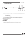
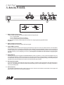
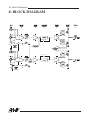
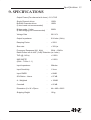
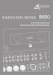
Installation & Operation Manual
AV2.2P
Dual Channel Audio Amplifier
Status A
AV2.2P
Power
Status B
Internal Revision Info
AUS, EUR, USA
Copyright
Rev A: 22nd Sept 2004
This symbol is intended to alert the user to the
presence of uninsulated “dangerous voltage”
within the product’s enclosure that may be of
sufficient magnitude to constitute a risk of electric
shock to persons.
CAUTION
RISK OF ELECTRIC SHOCK
DO NOT OPEN
CAUTION: TO REDUCE THE RISK OF ELECTRIC SHOCK.
DO NOT REMOVE COVER (OR BACK).
This symbol is intended to alert the user to the
presence of important operation and maintenance (servicing) instructions in the literature
accompanying the appliance.
NO USER-SERVICEABLE PARTS INSIDE.
REFER SERVICING TO QUALIFIED SERVICE PERSONNEL.
WARNING !
To prevent electric shock do not use this (polarized) plug
with an extension cord, receptacle or other outlet unless
the blades can be fully inserted to prevent blade exposure.
TO REDUCE THE RISK OF FIRE OR ELECTRIC SHOCK.
DO NOT EXPOSE THIS EQUIPMENT TO RAIN OR MOISTURE.
To prevent electric shock, match wide blade of plug to
wide slot, fully insert.
Caution:
AV2.2P
CONTENTS
Section
Page No.
1. Introduction
4
2. Front Panel
5
3. Back Panel
6
4. Installation
7
5. Operation
9
6 Maintenance
12
7. Dimensions
13
8. Block Diagram
14
9. Specifications
15
AV2.2P
4 Introduction
1. INTRODUCTION
The AMAV AV2.2P is a 1 RU stereo power amplifier. Designed for the demanding commercial audio-visual
market, the AV2.2P delivers 100 watts per channel at 4 ohms from an elegant, slim line package. The AV2.2P
features front panel dual colour status LEDs, on board limiter, ground lift switch and the option of bridged
operation delivering 200 watts at 8 ohms. Add to this the AV2.2P's whisper quiet operation, achieved via its
convection cooled design and you have an elegant, high quality audio amplifier. The AV2.2P offers the power and
the features demanded by any quality AV application.
AV2.2P
Front Panel 5
2. FRONT PANEL
1
2
Status A
1
Power
Status B
AV2.2P
3
1.
4
3
5
Status Indicators for Channels A and B
These are dual colour LEDs which indicate the status of the output stage. They indicate three levels of
operation:
Below 1 watt( unlit )
1 watt and above( green )
1dB below actual clipping( red )
2. Power ON indicator
This LED will illuminate Blue to indicate that the amplifier is ON and is receiving the mains power.
3. Attenuators for Channels A and B
Level control for the amplifier is provided by a potentiometers on the front panel. There are two such controls,
one for each channel.
4. Power ON Switch
Press the switch upwards for power On and downwards for power Off.
5. Rack Ears
The amplifier is supplied with a pair of Rack Ears for mounting the amplifier in a 19” Rack.
AV2.2P
6 Back Panel
3. BACK PANEL
2
5
1
BALANCED INPUT
CH-A
PUSH TO
GND LIFT
BALANCED INPUT
CH-B
OUTPUT - B
PUSH TO
BRIDGE
230V ~ 50 Hz 360VA
(F5) Fuse 2.0 A S.B.
OUTPUT - A
3
BRIDGE
ENGINEERED BY AUDIO TELEX COMMUNICATIONS PTY LTD SYDNEY AUSTRALIA
STEREO: 2x 100W/4 OHMS/ CLASS 2 WIRING
BRIDGED MONO: 200W/8 OHMS/ CLASS 2 WIRING
4
6
PIN 2
HOT
+
PIN 1
GND
PIN 2
HOT
+
PIN 1
GND
PIN 3
COLD
-
PIN 3
COLD
FEMALE XLR
MALE XLR
1. Balanced Input (Channel-A)
There is a pair of XLR connector provided for balanced signal input.
Pin 1 = Signal GND
Pin 2 = Hot (Non-inverting or In phase)
Pin 3 = Cold (Inverting or reverse phase)
A female XLR is wired in parallel with the male XLR for strapping/looping signal between
amplifiers.
2. Balanced Input (Channel-B)
Same as Channel - A but for Channel-B input signal.
3. Signal GND Lift switch
Pushing this switch IN disconnects signal ground from the input connectors on both channels. It is intended to
be used when ‘hum’ is caused by earth loops (due to different ground potentials between source equipment
and the amplifier) or stray magnetic field pick up on the input ground/shield wiring. (It does not interrupt signal
ground continuity on the strapping connector). The amplifier should be turned off before engaging this
switch!
4. Bridge Switch
Pushing this switch IN engages the BRIDGE/MONO mode of operation. In this mode the amplifier will only
accept signal applied to channel A’s input XLR’s and the level of both channels will be controlled by channel
A’s attenuator. The output from channel B will automatically be of the opposite polarity (reversed phase) and
speaker termination should be sourced from the Red binding-post outputs.
5. Binding Post Outputs
Touch proof binding posts (banana jacks) are provided for speaker output termination with banana plugs or
bare wire. The Red post is used as Positive and the Black post is used as Negative. For bridge connection,
use only the Red posts.
6. AC Power Inlet
The amplifier is fitted with an IEC mains inlet connector. Please ensure that the mains lead is of an approved
type and is of sufficient current carrying capacity.
AV2.2P
Installation 7
4. INSTALLATION
Power Requirements
Power consumption for your model AV2.2P amplifier is indicated on the rear panel for maximum output.
Ensure that your mains voltage is the same as the rear panel mains voltage marker (+/- 10%).
Mounting
The amplifier is designed as a table top model as well as for standard 19" rack mounting and occupies 1 EIA rack
unit (1.75"/44.45mm). The rack mounting ears are packed separately with the amplifier. The mounting centres
are:
Vertical: 1.26" (32mm)
Horizontal: 18.4" (467.36mm)
The slots in the mounting flange will accept bolt diameters up to 1/4" (6.35mm).
We recommend that you provide additional support for the amplifier, especially if road use is planned, as the
weight could bend some rack frames. This support can be provided by secure shelving, support rails or a rear
rack mounting strip to match up with the rear rack mount ears provided on your AV 2.2P amplifier.
Cooling
The AV2.2P uses a convection cooling system. The cabinet is designed to it allow the heat sink surface to cool
efficiently. One rack space should be provided above and below the amplifier for maximum cooling.
An unrestricted airflow to the unit must be provided. Any restriction of the air flow will cause heat to build up within
the amplifier.
If the amplifier is to be operated in an environment where the airflow is restricted (such as in sealed racks) cooling
should be supplemented by cooling fans to evacuate the heated air and boost the flow of cool air.
Input Wiring
IMPORTANT
Do not directly connect pin 1 on the amplifier’s input or strapping XLR to the amplifier’s chassis, speaker ground
or power ground!
NOTE : Input signal ground is not to be used as a safety ground (earth).
The input to the amplifier is a balanced 3-pin configuration and requires all three pins to be connected. Only high
quality twin-core shielded cable should be used.
When wiring for a balanced source, the connector going to the input of the amplifier should be wired as follows:
Pin 1 = GROUND / SHIELD.
Pin 2 = HOT (In Phase - non inverting).
Pin 3 = COLD (Reverse Phase - inverting).
When wiring from an unbalanced source, you must ensure that pin 3 is connected to pin 1 (input ground), either
by linking the pins in the input connector or by the source equipment's output wiring.
AV2.2P
8 Installation
When wiring for an unbalanced source:
Pin 1 =GROUND/SHIELD,
Pin 2 = HOT (in phase with the amplifier’s output),
Pin 3 = GROUND/SHIELD (joins to pin 1).
NOTE:
In-line XLR connectors often have a termination lug that connects directly to the chassis of the connector.
Do not link this lug to pin 1 at the amplifier’s input as it will defeat the amplifier’s input grounding scheme.
Output Wiring
When wiring to your speakers, always use the largest gauge wire your connector will accept. The longer the
speaker lead, the greater the losses will be, resulting in reduced power and less damping at the load. We
recommend using a heavy duty, two core flex (four core flex if bi-amping), 10 to 12 gauge (2mm2 to 2.5mm2 or
50/0.25 or equivalent) as a minimum.
When terminating to the 4 mm binding post (banana jack) output connectors, banana plugs or bare wires can be
used. The red terminal is positive and the black terminal is negative (ground).
If running in BRIDGE mode, only the red binding posts are used.
AV2.2P
Operation 9
5. OPERATION
IMPORTANT
All signal source equipment should be adequately earthed. This not only ensures your safety but
everybody else's as well. Faults can and do occur in mains connected equipment where the
chassis can become “live” if it is not properly earthed. In these instances, the fault in a “floating”
(ungrounded) piece of equipment will look for the shortest path to ground, which could possibly be
the amplifier's input. If the fault current is large enough, it will destroy the input to your amplifier and
look for the next available path, which may be you!
Before making any connections to the AV2.2P, observe the following:
Ensure the mains voltage supply matches the label on the rear panel of the amplifier (+/- 10%).
Ensure that the power switch is OFF.
Ensure that all system grounds (earth) are connected to a common point. Avoid powering equipment within a
system from multiple power sources that may be separated by large distances.
Check the continuity of all interconnecting leads to the amplifier; ensure that there are no open or short circuited
conductors.
Ensure that the power handling capacity of the load (speakers) can adequately cope with the power output of the
amplifier.
Before operating the AV2.2P, ensure that:
- The attenuators are at the “OFF” position (fully anticlockwise).
- The GROUND LIFT Switch is not engaged (should be in the “out” position).
- The BRIDGE Switch is not engaged if you are not running the amp in bridged mode.
Powering Up
REMEMBER
The amplifier should be the last piece of equipment that you turn on and the first piece of equipment that you
turn off.
We recommend turning the attenuators on the amplifier down when turning the unit on.
Level Matching
The normal operating position for the attenuator is the max position (fully clockwise, no attenuation). In this
position the amplifier operates at full gain. Turning the attenuator down (anticlockwise), reduces the input
sensitivity.
NOTE:
If full power output is required, you should operate the amplifier with the front panel attenuator above the half way
(12 o’clock) position, otherwise clipping of the input circuitry with resultant distortion will occur before full output
power is achieved.
Sensitivity
The amplifier is a linear device operating with a fixed input-to-output voltage gain (less attenuation). The
maximum output voltage swing is determined by the applied mains voltage, load, load type and the duty cycle of
the applied signal.
The input sensitivity for the AV 2.2P when the attenuator is at maximum position (fully clockwise) is nominally:
+ 4.0 dBu (1.23 Volts) for rated Power into a 8 ohm load.
AV2.2P
10 Operation
+ 2.2 dBu (1.0 Volts) for rated Power into a 4 ohm load.
The signal source (i.e. the equipment feeding signal to the amplifier) should have an output impedance
of 600 Ohms or lower to avoid unwanted high frequency loss in the cabling.
Input overload occurs at +19.10dBu (7.00 volts).
Hum Problems
Most equipment is designed for minimum hum when used under ideal conditions. When connected to other
equipment, and to a safety earth in an electrically noisy environment, problems may occur.
The three "E"s of hum and hum related noise which can plague an audio system are:
a) Electrostatic radiation,
b) Electromagnetic radiation, and
c) Earth loops
Electrostatic radiation capacitively couples system elements, causing an interference voltage that mainly
affects higher impedance paths, such as amplifier inputs. The source is generally a nearby high voltage, such
as a mains lead or a speaker lead. The problem can usually be reduced by moving the offending lead away, or
by providing additional electrostatic shielding (i.e. an earthed conductor which forms a barrier to the field).
Electromagnetic radiation induces interference currents into system elements that mainly effect lower
impedance paths. Radio transmitters or stray magnetic fields from mains transformers are often the cause of
this problem. It is generally more difficult to eliminate this kind of interference, but again, moving the source
away or providing a magnetic shield (i.e. a steel shield) should help.
Earth loops can arise from the connection of the various pieces of equipment and their connection to
different safety earths. This is by far the most common cause of hum, and it occurs when source equipment
and the amplifier are plugged into different points along the safety earth, where the safety earth wiring has a
current flowing through it. The current flowing through the wire produces a voltage drop due to the wire’s
resistance. This voltage difference between the amplifier earth and source equipment earth appears to the
amplifier's input as a signal and is amplified as hum.
There are three things you can do to avoid earth loop problems:
Ensure the mains power for the audio system is “quiet” i.e. without equipment on it such as air-conditioning,
refrigeration or lighting which may generate noise in the earth circuit.
Ensure all equipment within the system shares a common ground/ safety earth point. This will reduce the
possibility of circulating earth currents, as the equipment will be referenced to the same ground potential.
Ensure that balanced signal leads connecting to the amplifier are connected to earth at one end only.
Signal Ground-Lift Switch
When proper system hook-up has been made, you may still have some hum or hum related noise. This may
be due to any of the previously mentioned problems.
The AV2.2P has a “Signal Ground Lift” switch which disconnects the input ground wiring from the amplifier. A
substantial drop in hum and/or hum related noise can result from the judicious use of this switch.
AV2.2P
Operation 11
NOTE
If the input ground lift switch is used, you must ensure adequate shielding of the input wiring. If the signal source
equipment does not provide adequate shielding (i.e. a definitive connection to ground), you must disconnect the
shield from the input connector's ground pin (Pin-1) and re-connect it to the "drain" contact on the input
connector. This will ensure the shield on your input wiring actually goes to the amplifier chassis and subsequently
to earth.
DO NOT CONNECT PIN-1 DIRECTLY TO THE DRAIN CONNECTION.
You will defeat the amplifiers internal grounding scheme and possibly cause instability in the amplifier.
Always ensure that the amplifier is off and the attenuators are turned down when you engage this switch. This
switch should only be used when the amplifier is operated from a balanced signal source.
NOTE: Be wary of quasi-balanced outputs, these are often no more than floating unbalanced outputs.
AV2.2P
12 Maintenance
6. MAINTENANCE
Only competent or qualified persons should attempt any service or maintenance of the amplifier.
Your AV2.2P needs minimal maintenance. No internal adjustments need to be made to the amplifier
to maintain optimum performance.
To provide years of reliable operation, we suggest a maintenance inspection be carried out every 12
months.
Heat Sink
The surface of the Heat Sink may become covered with dust over time, reducing it’s efficiency. The heat sink
should be cleaned as part of routine maintenance.
Fuses
Along with the rear panel mains fuse, there are four (4) rail fuses provided internally in the unit. These
rail fuses are in series with the positive and negative output supply to each amplifier channel and
provide overall protection for the output stage. If the amplifier is subjected to heavy use such as short
circuits, these fuses will eventually fatigue and may require replacing.
NOTE
Make sure the unit is off and is unplugged from the mains. Give the main filter capacitors time to discharge before
removing lids and inspecting the fuses.
You should replace any fuse if it’s element is sagging or discoloured. Only ever replace with the same type fuse
and current rating.
When checking for a failed fuse, do not rely on visual inspection alone. You should use an ohm meter to check
continuity.
AV2.2P
Dimensions 13
7. DIMENSIONS
44.0 mm
32.0 mm
482.0 mm
467.0 mm
Status A
Power
Status B
AV2.2P
442.0 mm
BALANCED INPUT
CH-B
BALANCED INPUT
CH-A
PUSH TO
BRIDGE
OUTPUT - B
PUSH TO
GND LIFT
230V ~ 50 Hz 360VA
(F5) Fuse 2.0 A S.B.
OUTPUT - A
BRIDGE
ENGINEERED BY AUDIO TELEX COMMUNICATIONS PTY LTD SYDNEY AUSTRALIA
STEREO: 2x 100W/4 OHMS/ CLASS 2 WIRING
BRIDGED MONO: 200W/8 OHMS/ CLASS 2 WIRING
283.5 mm
16.0 mm
AV2.2P
14 Block Diagram
8. BLOCK DIAGRAM
OFF
ON
22E
O/P (A) Current limit
O/P (B) Current limit
OFF
22E
AV2.2P
ON
Specifications 15
9. SPECIFICATIONS
Output Power (Per channel at 4 ohms) 0.1% THD
Single Channel driven
Both/All Channels driven
(2 ohm loads not recommended)
:
:
120W
100W
Bridge mode : 8 ohm
:
(4 ohm bridging not recommended)
200W
Voltage Gain
:
20.0 V/V
Output Impedance
:
0.04 ohm (1kHz)
Damping Factor
:
> 200:1
Slew rate
:
> 30V/µs
Frequency Response (@ 1 KHz)
:
20Hz ~ 60KHz
Rated Power into 4 ohm (-3 dB) Distortion (re 4 ohm)
THD (@ 1 KHz)
:
< 0.02%
IMD SMPTE
(60Hz : 7 KHz 4 : 1)
:
< 0.03%
Input Impedance
:
20kohm
Input Sensitivity
:
1 Vrms
Input CMRR
:
> 80dB
S/N Ration : Linear
:
> 97 dB
A - Weighted
:
> 100dB
Crosstalk
:
> 65 dB
Dimension (H x W x D)mm
:
44 x 482 x 299.5
Shipping Weight
:
10 kg
AV2.2P
AUSTRALIA and NEW ZEALAND
www.australianmonitor.com.au
Sydney
(NSW & ACT Sales)
Brisbane
(Qld Sales)
Perth
(WA Sales)
Private Bag 149, Silverwater NSW 1811
149 Beaconsfield Street, Silverwater
NSW 2128
Ph: (02) 9647 1411
Fax: (02) 9648 3698
E-mail: [email protected]
P.O. Box 871, Fortitude Valley QLD 4006
42 Commerical Road, Fortitude Valley
QLD 4006
Ph: (07) 3852 1312
Fax: (07) 3252 1237
E-mail: [email protected]
P.O. Box 404, North Perth WA 6906
299 Fitzgerald Street, West Perth WA 6005
Ph: (08) 9228 4222
Fax: (08) 9228 4233
E-mail: [email protected]
Melbourne
(Vic & Tas Sales)
Adelaide
(SA & NT Sales)
P.O. Box 151, Blackburn South VIC
3130
22/277 Middleborough Road, Box Hill
VIC 3128
Ph: (03) 9890 7477
Fax: (03) 9890 7977
E-mail: [email protected]
P.O. Box 157, Hindmarsh SA 5001
31 Walsh Street, Thebarton SA 5031
Ph: (08) 8352 4444
Fax: (08) 8352 4488
E-mail: [email protected]
Auckland
(NZ Sales)
P.O. Box 512, Albany 1331
Unit B, 11 Piermark Drive, Albany 1331
Ph: (09) 415 9426
Fax: (09) 415 9894
E-mail: [email protected]
EUROPE/ASIA/MIDDLE EAST
www.australianmonitor.com.au
International Sales
Private Bag 149, Silverwater NSW 1811
149 Beaconsfield Street, Silverwater NSW 2128
Australia
Ph: 61-2- 9647 1411
Fax: 61-2-9748 2537
E-mail: [email protected]