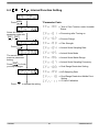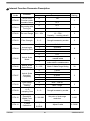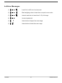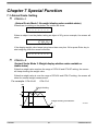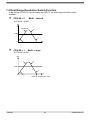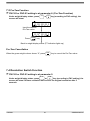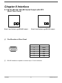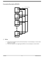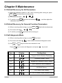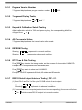
1
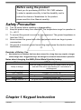
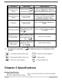
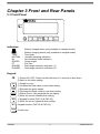
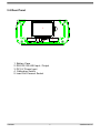
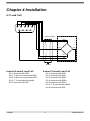
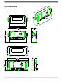
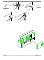
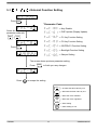
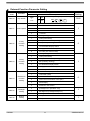
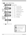
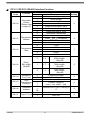
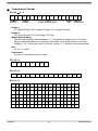
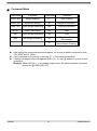
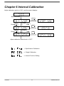
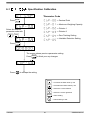
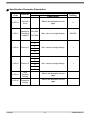
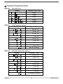
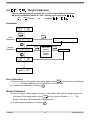
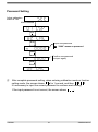
A Higher Level of Precision… A Higher Level of Performance Intell-Weigh 10™ Indicator NTEP Approved 10,000 Divisions, COC # 10-010 User Operation Manual Table of Contents Safety Precaution ....................................................................................................................... 3 Chapter 1 Keypad Instruction ................................................................................................... 3 Chapter 2 Specifications ........................................................................................................... 4 Chapter 3 Front and Rear Panels ............................................................................................. 6 3-1 Front Panel .................................................................................................................... 6 3-2 Rear Panel ..................................................................................................................... 7 Chapter 4 Installation................................................................................................................. 8 4-1 Load Cell ....................................................................................................................... 8 4-2 Dimensions ................................................................................................................... 9 4-3 Battery Assemble ....................................................................................................... 10 Chapter 5 External Function Parameter Setting .................................................................... 11 5-1 External Function Setting ........................................................ 12 5-2 RS-232 Setting .......................................................................... 14 Chapter 6 Internal Calibration ................................................................................................. 19 6-1 Specification Calibration .......................................................... 20 6-2 Weight Calibration .................................................................... 23 6-3 Internal Function Setting .......................................................... 25 6-4 Error Messages ........................................................................................................... 27 Chapter 7 Special Function ..................................................................................................... 28 7-1 Animal Scale Setting .................................................................................................. 28 7-2 Dual Range Resolution Switch Function .................................................................. 29 7-3 Pre-Tare Function ....................................................................................................... 30 7-4 Resolution Switch Function....................................................................................... 30 Chapter 8 Interface .................................................................................................................. 31 8-1 OP-01 RS-232 / RS-485 Serial Output with RTC (Real Time Clock) ........................ 31 Chapter 9 Maintenance ............................................................................................................ 33 9-1 Default Recovery for All Parameters ......................................................................... 33 9-2 Default Recovery for General Function Parameters ................................................ 33 9-3 Self-diagnosis Mode ................................................................................................... 33 9-3-1 Program Version Number.............................................................................. 34 9-3-2 7-Segment Display Testing ........................................................................... 34 9-3-3 Keypad & Calibration Switch Testing ........................................................... 34 9-3-4 A/D Conversion Value.................................................................................... 34 9-3-5 EEPROM Testing ............................................................................................ 34 9-3-6 RTC Time & Date Testing .............................................................................. 34 9-3-7 RS-232 Serial Output Interface Testing ( OP-01 ) ........................................ 34 Appendix 7-SEGMENT DISPLAY CHARACTERS ................................................................... 35 FM/FMR 1 ZSME300000103 FM/FMR 2 ZSME300000103 Before using the product Thank you for purchasing EXCELL FM / FMR indicator. In order to operate smoothly, to last the durability, and to reduce the chance of breakdown for this product, please read this User Manual carefully. Safety Precaution Turn off power before installing or disassembling. Keep the product away from sunshine. The temperature range for operation is 0 ~ +40 ℃. To connect the ground is a must for this equipment. The ground impedance is less than 100 . Never connect the ground with other equipments which are huge in power consumption. No ground or incorrect ground connecting might cause the electric shocks or breakdowns. Reminder of Battery Use: ! New batteries or batteries that have been stored for a long time may require a longer initial charge time. Suggest having a full charge for at least 8 hours before operation. Notes about charging the NiMH (Nickel-Metal Hydride) battery: Status Ready to charge During charging Finish charging Battery fault Without battery Battery voltage is below 2.5 V LED Description Once the scale is connected with AC power mains, the green and red LEDs will be inter-flashing for 3 seconds as a self-diagnosis. The red LED will be ON. The green LED will be ON. The green and red LEDs keep inter-flashing without stop. The red LED will be ON. The green and red LEDs keep inter-flashing without stop. Chapter 1 Keypad Instruction FM/FMR 3 ZSME300000103 Function General Function Setting Operation Press and hold and then press , ENTER F1 Refer to <Chapter 5> External Function Parameter Setting for details Weighing Parameter Setting Adjust calibration switch to ON Setting for decimal point, capacity, division, zero tracking, and unstable detection, etc. Refer to 6-1 Specification Setting for details. Calibration Adjust calibration switch to ON Refer to 6-2 Weight Calibration for details. While turning on with Self-diagnosis Mode countdown, press and ZERO hold Refer to 9-3 Self-diagnosis Mode for details. Adjust calibration switch Default Recovery for to ON, and then press All Parameters and hold F1 ENTER . Refer to 9-1 for details. While turning on with Default Recovery for countdown, press and General Function hold F1 ENTER. Parameters Refer to 9-2 for details. F1 Description ENTER During the operation, use the following keys to complete all the works. ZERO TARE GROSS NET F2 Increase the flash value by one ENTER Decrease the flash value by one Move the cursor leftward ESC Move the cursor rightward Save setting Abort setting / Exit Chapter 2 Specifications Analog Specification Load Cell Current Max. Load Cell Input Voltage FM/FMR : DC 5 V 5% 60 mA (Up to Four 350 Ω Load Cells) : 16 mV 4 ZSME300000103 Input Sensitivity Conversion Rate Resolution : 0.15 V/d or more : Approximately 120 times/s (max.) : 20 bits Digital Specification Display Display Frequency Display Range Min. Division Decimal Point Memory : LCD, 6 digits, 25.4 x 10 mm (W x H), LED backlight (Black digits for FM; Red digits for FMR) : 50 times/s (max) : - 999 999 ~ 999 999 : 1, 2, 5, 10, 20, 50 : 0, 0.0, 0.00, 0.000, 0.0000 : Calibration parameter and function setting are all stored in EEPROM. Optional Interface Card OP-01 RS-232 / RS-485 (Includes RTC Function) Power Requirement Adaptor Spec Optional 2 types of batteries Max. Power Consumption : Input 120 / 230 V AC 50 ~ 60 Hz Output 9 V / 1000 mA : 6 V NiMH rechargeable battery kit (5 pcs) (1800 mA/hr) or general batteries (5 pcs) :110 mA (with 4 Load Cells + backlight + RS-232 interface) NiMH battery → 15 hours General battery → 24 hours 45 mA (with 1 Load Cell + no backlight + no RS-232 interface) NiMH battery → 36 hours General battery → 60 hours Others Operation Temperature : 0 ~ 40 ℃ Operation Humidity : < 85% R.H. Dimensions (W D H) (mm) : 193 49.5 94.4 (excluding protrusions) 225 60 134.7 (including protrusions) Weight : 700 g FM/FMR 5 ZSME300000103 Chapter 3 Front and Rear Panels 3-1 Front Panel R + - TARE ESC MOTION ZERO + M+ TARE GROSS GROSS NET PT RANGE 1 F2 RANGE2 F1 ENTER Indication: : Battery charged status (only available to charged model) : TARE : MOTION : M+ : GROSS : PT : RANGE1 : RANGE2 : Battery charging status (only available to charged model) Tare mode Unstable weighing indication Accumulation mode indication Gross weight Pre-Tare Dual-range resolution indication (1) Dual-range resolution indication (2) Keypad: ESC 1) Power ON / OFF. Press and hold this key for 3 seconds to shut down. 2) Abort or exit when setting. ZERO 1) Weight re-zero. 2) Increase the flash value by one when setting. TARE 1) Eliminate the gross weight. 2) Decrease the flash value by one when setting. GROSS NET 1) Switch Gross / Net weight shown on display. 2) Move the cursor leftward when setting. F2 1) Keypad function (FNC-02 & FNC-03). 2) Move the cursor rightward when setting. F1 Keypad function (FNC-02 & FNC-03). ENTER FM/FMR Confirm key. 6 ZSME300000103 3-2 Rear Panel 1 2 5 3 4 MINI INDICATOR後蓋(ABS) ABS RoHS材質限制: ˙ 鎘:100ppm以下 ˙ 鉛、汞、六價鉻、多溴聯苯、多溴二苯醚:1000ppm以下 1. Battery Case 2. RS-232 / RS-485 Input / Output 3. DC 9 V Power Input 4. Calibration Switch 5. Load Cell Connect Socket FM/FMR 7 ZSME300000103 Chapter 4 Installation 4-1 Load Cell 4 5 9 2 3 8 7 1 6 Load cell cable Load cell EXC+ SEN+ SIG+ SIG- EXCSEN- Shield 4-wired (5-wired) Load Cell 6-wired (7-wired) Load Cell Pin 1 connects with SIG+ Pin 2, 3 short to connect with EXCPin 4, 5 short to connect with EXC+ Pin 6, 7, 8 connects with shield Pin 9 connects with SIG- FM/FMR Pin 1 connects with SIG+ Pin 2 connects with EXCPin 3 connects with SENPin 4 connects with SEN+ Pin 5 connects with EXC+ Pin 6, 7, 8 connect with shield Pin 9 connects with SIG- 8 ZSME300000103 4-2 Dimensions FM/FMR 9 ZSME300000103 4-3 Battery Assemble 將多餘的電線塞入電池孔中 Stuff the surplus wires into the battery case. FM/FMR 10 ZSME300000103 Chapter 5 External Function Parameter Setting Under general weight display status, press F1 ENTER , and the screen will show: ENTER Press ZERO Press TARE key key ENTER ESC Press to escape. Back to weight display status. External function setting RS-232 / RS-485 interface function FM/FMR 11 ZSME300000103 5-1 b External Press Function Setting ENTER *Parameter Code Key Disable Select the desired parameter code with ZERO / DSP Update (Display Update) F1 Key Function Setting TARE F2 Key Function Setting Press ENTER+F2 Function Setting ENTER Backlight Function Setting Beeper Setting The screen shows previous parameter setting. Press Press ESC ENTER . to finish your any changes to escape the setting ZERO TARE Decrease the flash value by one GROSS NET Move the cursor leftward F2 ENTER ESC FM/FMR 12 Increase the flash value by one Move the cursor rightward Save setting Abort setting or exit ZSME300000103 External Function Parameter Setting Parameter Code Function FNC-00 Key disable FNC-01 FNC-02 FNC-03 FNC-04 FNC-05 FNC-06 FM/FMR DSP Update F1 Key Function Setting F2 Key Function Setting ENTER+F2 Function Setting Backlight Setting Beeper Setting 0000 1111 Default Setting Setting Value Description Parameter 0 ON 0000 is corresponding to:(from left to right) ZERO 1 OFF TARE GROSS NET 0000 F2 0 No Limit 1 20 times/s 2 10 times/s 3 5 times/s 4 1 times/s 0 Print (printing) 1 Units (units switch) 2 M+ (accumulation and printing) 3 MC (memory clearing) 4 Weight / Weight Accumulation / Times Accumulation Display Switch 5 HR (high resolution switch) 6 Pre-Tare (Pre-Tare function) 0 Print (printing) 1 Units (units switch) 2 M+ (accumulation and printing) 3 MC (memory clearing) 4 Weight / Weight Accumulation / Times Accumulation Display Switch 5 HR (high resolution switch) 6 Pre-Tare (Pre-Tare function) 0 Print Function (Print) 1 Units Shift (Units) 2 Accumulation and Print (M+) 3 Clean the Accumulation Value (MC) 4 Weight / Accumulation Value / Accumulation Times Shift Display 5 Resolution Conversion 0 Auto Backlight On (backlight on in operation only) 1 Backlight On (backlight always on) 2 Backlight Off 0 Beeper off 1 Beeper on 13 1 5 1 0 1 1 ZSME300000103 5-2 RS-232 Setting *Parameter Code Information Pattern ENTER Press Transmission Method Transmission Rate Select the desired parameter code with ZERO / Parity, Bit Length, Stop Bit Unstable or Over Load TARE Auto Transmission Condition Command Address Press ENTER Output Format Transmission Times The screen shows previous parameter setting. ENTER Press to finish your any changes Press ESC Date Setting Time Setting to escape the setting. ZERO TARE Decrease the flash value by one GROSS NET Move the cursor leftward F2 ENTER ESC FM/FMR 14 Increase the flash value by one Move the cursor rightward Save setting Abort setting or exit ZSME300000103 OP-01 / RS-232 / RS-485 Interface Function Parameter Code Function RS1-00 Information Pattern (Please refer to page 16) RS1-01 Transmission Method RS1-02 Transmission Rate RS1-03 Parity, Bit Length, Stop Bit RS1-04 Unstable or Over Load RS1-05 Auto Transmission Condition RS1-06 Command Address RS1-07 Output Format FM/FMR Setting Value Default Setting Parameter Description 0 Display Correspondingly 1 Gross Weight 2 Net Weight 3 Tare 0 4 Weight Accumulation Value 5 Times Accumulation Value 6 Output with Date & Time 0 Continuous Transmission 1 Auto Transmission 2 Press or to transmit 0 3 Command Mode (no address) 4 Command Mode (with address) 0 1 200 1 2 400 2 4 800 1 3 9 600 4 19 200 No Parity N、8、1 0 8 Bits Length 1 Stop Bit Odd Parity, O、7、1 1 7 Bits Length, 2 1 Stop Bit Even Parity, E、7、1 2 7 Bits Length, 1 Stop Bit 0 Continuous Output 0 1 Stop Output 0 Positive (over + 10d) 0 Positive / Negative 1 (over + 10d, under – 10d) 00 Available only if RS1-01 setting is 0 “4” 99 F1 0 1 F2 Standard Format UMC 600 15 0 ZSME300000103 FM/FMR RS1-08 Transmission Times RS1-09 RS1-10 Date Setting Time Setting 0 1 2 3 4 5 No Limit 1 times/s 2 times/s 5 times/s 10 times/s 20 times/s YY.MM.DD HH.MM.SS 16 4 ZSME300000103 Transmission Format RS1-00 0 ~ 3 S , T Header 1 G S , + 1 Header 2 2 3 . 4 5 6 g CR LF Weight Data (8 digits) Unit Terminators Header 1 ST: Stable Weight / US: Unstable Weight / OL: Weight Overload Header 2 GS: Gross Weight / NT: Net Weight / TR: Tare Weight Data (8 digits) The first digit of weight data represents “+ / -“indication for weight value. The other 7 digits, including decimal point, represent the weight value. If the weight is over load (Header 1: OL), the screen turns into “blank” except “+ / -“indication and decimal point. Unit kg, lb, t or “blank” Terminators CR and LF are data termination code. RS1-00 = 4 T N , 1 2 3 CR LF , + 1 2 3 4 . RS1-00 = 5 T W 5 6 k g CR LF X X CR LF RS1-00 = 6 D A T E : 2 0 X X / X X / T I M E : X X : X X : X X CR LF G R O S : + 1 2 3 4 . 5 6 k g CR LF N E T : + 1 2 3 4 . 5 6 k g CR LF T A R : + 1 2 3 4 . 5 6 k g CR LF T N : X X X CR LF T W : + 1 2 . 5 6 k g CR LF FM/FMR E S 3 4 17 ZSME300000103 Command Mode Command Function Command Function READ / RW Weight Reading CT Tare Clearing ZERO / MZ Weight Re-zeroing Rl Weight Accumulation Rm Times Accumulation TARE / MT Gross Weight Deducting NTGS Gross / Net Switch Rn Date MG Gross Weight Indicating Ro Time MN Net Weight Indicating AT DT Weight and Times Accumulation Weight and Times Accumulation Clearing After setting the commands mentioned above, it’s a must to add the termination code “CR (0DH) and LF (0AH)”. If the command is not correct, it will reply “E” + “Command Unidentified”. If setting command mode with address (RS1-01 = 4), add “@ address” in front of each command. Example: When RS1-06 = 1, for reading weight value, the whole complete command should be “@01RW (CR) (LF)”. FM/FMR 18 ZSME300000103 Chapter 6 Internal Calibration Adjust calibration switch to “ON”, and the screen displays: After 2 seconds ENTER Press ZERO Press TARE ENTER Press ZERO Press TARE ENTER Adjust calibration switch back to “OFF”. Specification Calibration Weight Calibration Internal Function Setting FM/FMR 19 ZSME300000103 6-1 Specification Calibration *Parameter Code Press ENTER Decimal Point Maximum Weighing Capacity Division 1 Select the desired parameter code with ZERO / Division 2 TARE Zero Tracking Setting Unstable Detection Setting Press ENTER The screen shows previous parameter setting. Press Press ESC ENTER . to finish your any changes to escape the setting ZERO TARE GROSS NET F2 ENTER ESC FM/FMR 20 Increase the flash value by one Decrease the flash value by one Move the cursor leftward Move the cursor rightward Save setting Abort setting or exit ZSME300000103 Specification Parameter Description Parameter Function Code Parameter CSP-00 Decimal Point CSP-01 Maximum Weighing Capacity 999 999 000 000 Setting Value Description Default Setting Refer to the description on next page 0 Max. value for weight display 999 999 Min. value for weight display 1 Min. value for weight display 1 1 2 CSP-02 Division 1 5 10 20 50 1 2 CSP-03 Division 2 5 10 20 50 CSP-04 Zero Tracking Setting Refer to the description on next page CSP-05 Unstable Detectiion Setting Refer to the description on next page FM/FMR 21 ZSME300000103 Parameter Display Description CSP-00 Decimal Point Display Decimal Point Digit None CSP-04 . 1 digit . 2 digits . 3 digits . 4 digits Zero Tracking Setting Display Division/Time 0.25 d / 1 s . 0.5 d / 1 s . 0.75 d / 1 s . 1d / 1 s 1.25 d / 2 s . 1.5 d / 2 s . 1.75 d / 2 s . 2 d / 2s No Zero Tracking CSP-05 Unstable Detection Setting Display Division / Time 0.25 d / 1 s . 0.5 d / 1 s . 0.75 d / 1 s . 1d / 1 s 1.25 d / 2 s . 1.5 d / 2 s . 1.75 d / 2 s . 2d/2s No Unstable Detection FM/FMR 22 ZSME300000103 6-2 Weight Calibration Turn on and warm up the machine for 15 to 30 minutes before calibration. Adjust the calibration switch to “ON”, and the screen will show TARE ZERO Press or to select . . Procedure ENTER ENTER Zero Calibration Zero calibration completed ESC ENTER Weight Calibration ESC Place the weight mass and set the weight ENTER Confirmed Set calibration switch to “OFF” Zero Calibration ENTER a) Ensure nothing on the platter; after being stable, press , and the screen will display “……. ”. The zero calibration will be complete 5 seconds later. b) To abort zero calibration, just press ESC . Weight Calibration a) Place an object, whose weight is known, on the platter, and input the weight value from front panel. After being stable, press ENTER and the screen will show “……. ”. The weight calibration will be complete 5 seconds later. b) To abort weight calibration, just press FM/FMR ESC 23 . ZSME300000103 Password Setting Adjust calibration switch to “ON” After 2 seconds ZERO F1 Input new password “0000” means no password. ENTER Confirm new password (re-input again) ENTER After complete password setting, when entering calibration mode or function setting mode, the screen shows for 1 second, and then . It’s necessary to input the correct password to continue each setting. If the input password is not correct, the screen shows FM/FMR 24 . ZSME300000103 6-3 Internal Function Setting Press ENTER *Parameter Code Tare or Zero Function under Unstable Status Select the desired parameter code with ZERO Re-zeroing after Turning on ZERO Re-zero Range / Filter Strength Press ENTER Animal Scale Sampling Rate Animal Scale Mode The screen shows previous parameter setting. Animal Scale Stable Range Animal Scale Sampling Frequency ENTER Press to finish your any changes. Dual Range Resolution Setting A/D Sampling Rate Dual Range Resolution Middle Point Setting G Value Calibration Press FM/FMR ESC to escape the setting 25 ZSME300000103 Internal Function Parameter Description Setting Value Description Parameter Code Function 0 ON CFN-00 Tare or Zero Function under Unstable Status 1 OFF Re-zeroing after Turning on 0 OFF 1 ON CFN-02 Re-zero Range 0% ~ 30% 0%: Full range re-zero 1% ~ 30%: Capacity setting value% 2 CFN-03 Filter Strength 0~5 Strength increases by number 2 0 1 2 3 0 No limit 20 times/s 10 times/s 5 times/s OFF Mode 1: No weight shows under unstable status Mode 2: Weight shows no matter under stable or unstable status CFN-01 CFN-04 Animal scale Sampling Rate CFN-05 Animal Scale Mode Parameter 1 1 1 2 Animal Scale Stable Range 0 ~ 100 CFN-07 Animal Scale Sampling Frequency 0 1 2 3 4 CFN-08 Dual Range Resolution Setting CFN-09 A/D sampling Rate 0~9 CFN-10 Dual Range Resolution Middle Point Setting 0 ~ 999 999 CFN-11 G Value Calibration 9.78032 | 9.83218 CFN-06 FM/FMR Default Setting Mode 2: Stable Range Setting 8 times 16 times 32 times 64 times 128 times 0 Multi - interval 1 Multi - range Strength increases by number Set point of dual-range resolution Adjust G value 26 0 0 30 2 0 4 5 000 9.79585 ZSME300000103 6-4 Error Messages (1) Load Cell or A/D circuit is abnormal (2) Real weighing value is lower than or equal to zero value (3) Internal resolution is lower than 0.15 μV/d range (4) . Incorrect password (5) Internal value is higher than zero range (6) Internal value is lower than zero range FM/FMR 27 ZSME300000103 Chapter 7 Special Function 7-1 Animal Scale Setting CFN-05 = 1 (Animal Scale Mode1: No weight display under unstable status) When there is nothing on the platter, the screen will show: When an object is on the platter, taking an object of 20 g as an example, the screen will show: . If the display weight value keeps being lower than zero plus 10d or press Enter key to start weighing, then the screen will show: CFN-05 = 2 (Animal Scale Mode 2: Weight display whether under unstable or stable status) When the weight value reaches the range of CFN-06 and CFN-07 setting, the screen will keep showing the weight value. When the weight value is over the range of CFN-06 and CFN-07 setting, the screen will show the normal weight measurement. For example: CFN-06=30 CFN-07=2 WT Weight Holding 30d Weight Holding Cancellation 32 Times 10d FM/FMR T 28 ZSME300000103 7-2 Dual Range Resolution Switch Function If the setting of CSP-02 is not the same as CSP-03, the dual range resolution will be available. CFN-08 = 0 Multi - interval If CFN-09 = 5 000 WT Division 2 2 5 000 1 T 0 Division 1 CFN-08 = 1 Multi - range If CFN-09 = 5 000 WT 2 2 5 000 T T 0 1 FM/FMR 2 Recover when back to zero 29 ZSME300000103 7-3 Pre-Tare Function FNC-02 or FNC-03 setting is at parameter 6. (Pre-Tare Function) Under weight display status, press screen will show: F1 or F2 key (according to FNC setting), the Input the desired Pre-Tare value Press ENTER key Back to weight display status (PT indication lights up) Pre-Tare Cancellation When the gross weight column shows “0”, press TARE key to cancel the Pre-Tare value. 7-4 Resolution Switch Function FNC-02 or FNC-03 setting is at parameter 5. F1 F2 Under weight display status, press or key (according to FNC setting), the screen will show 10 times resolution and recover the original resolution after 5 seconds. FM/FMR 30 ZSME300000103 Chapter 8 Interface 8-1 OP-01 RS-232 / RS-485 Serial Output with RTC (Real Time Clock) CN2 CN3 CN2 CN3 123 123 123 123 Short 1 and 2 pins to get RS-485 output. Pin Allocation of Rear Panel 4 5 9 Short 2 and 3 pins to get RS-232 output. 8 1 2 3 7 6 Pin Function 2 RXD 3 TXD 5 SG 6 DA 7 DB RS-485 interface is capable to connect up to 10 mini-indicators. FM/FMR 31 ZSME300000103 Connection Description (RS-485) Terminal Resistant Host EX0419 # 1 RS - 06 = 01 EX0419 # 2 RS - 06 = 02 EX0419 # 10 RS - 06 = 10 Notice If the terminal resistant is built-in the host interface, it’s not necessary to connect with another one outside. If the host computer is no signal ground (SG), it’s not necessary to connect with it. FM/FMR 32 ZSME300000103 Chapter 9 Maintenance 9-1 Default Recovery for All Parameters (1) Adjust the calibration switch to “ON”, when re-zeroing after turning on, press F1 ENTER and hold them simultaneously. . (2) The screen will show ENTER (3) To confirm, press and hold until showing calibration switch to “OFF”. , and then adjust the 9-2 Default Recovery for General Function Parameters (1) When re-zeroing after turning on, press ENTER ENTER and hold simultaneously. . (2) The screen will show (3) To confirm, press F1 and hold until re-turning on. 9-3 Self-diagnosis Mode (1) When re-zeroing after turning on, press (2) The screen will show (3) Use ZERO Press Item FM/FMR or ENTER TARE ZERO and hold. , which means entered self-diagnosis mode. keys to select item intended to test. key to enter self-diagnosis, and press Display ESC key to exit. Testing Item 1 Program Version Number Displaying 2 7-Segment Display Testing 3 Keypad and Calibration Switch Testing 4 A/D Conversion Value Displaying 5 EEPROM Testing 6 RTC Date & Time Testing 7 OP-1 RS-232 Serial Output Interface Testing 33 ZSME300000103 9-3-1 Program Version Number 7-Segment display shows program version number XX. 9-3-2 7-segment Display Testing 7-Segment display shows to and “.”. 9-3-3 Keypad & Calibration Switch Testing Adjust calibration switch to “ON”, and press any key, the corresponding bit will be changed from 9-3-4 to . A/D Conversion Value 7-Segment display shows the internal value of the scale. 9-3-5 EEPROM Testing Showing represents in normal condition. Showing represents in abnormal condition. 9-3-6 RTC Time & Date Testing Press ENTER key to enter the testing mode, and the screen will show date YY.MM.DD. Example: “05.11.03” represents 3rd of November, 2005. Press ENTER key again to show time HH.MM.SS. Example: “09.45.50” represents 9 o’clock, 45 minutes and 50 seconds. 9-3-7 RS-232 Serial Output Interface Testing ( OP - 01 ) (1) Short Pin 2 and Pin 3 of the 9-pin D-SUB socket of serial output. Showing represents in normal condition. Showing represents in abnormal condition. (2) If connected with a computer (protocol must be corresponding), the screen will show to FM/FMR , which means RS-232 output is in normal condition. 34 ZSME300000103 Appendix 7-SEGMENT DISPLAY CHARACTERS Number Letter Display Letter 0 A N 1 B O 2 C P 3 D Q 4 E R 5 F S 6 G T 7 H U 8 I V 9 J W K X L Y M Z ℃ FM/FMR Display 35 Display ZSME300000103 Intelligent Weighing Technology has more than 50 years experience in the weighing industry,both in the USA and worldwide. With contacts in over 50 countries including the USA, we provide you with the weighing equipment you need. When you invest in weighing equipment from Intelligent Weighing Technology, you’re really buying peace of mind. Quality - Scales and balances solidly built from the ground up with superior engineering and components for exacting results. Value - From bench scales to analytical balances, weighing equipment priced for real-world business applications, with superior service and support. Experience - Expert advice to help you choose just the right product for your application. Quality + Value + Experience…it adds up to the Intelligent Investment. Intelligent Weighing Technology, Inc. www.intelligentwt.com FM/FMR 36 ZSME300000103