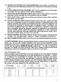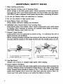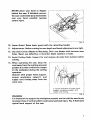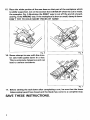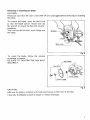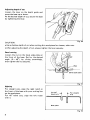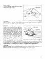
1
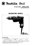
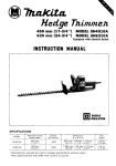
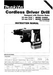
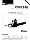
Square Cut Saw
185 mm (744”) MODEL 5007s
INSTRUCTION MANUAL
DOUBLE
INSULATION
SPECIFICATIONS
Blade
diameter
185 mm
(7-1/4”)
Max. cutting capacities
900
58.5mm
(2-5/16”)
450
45.5 mm
(1-3/16“)
No load speed
(RPM)
5,800
Overall
length
395 mm
(15-112“)
* Workpieces up t o 2 x 10 can be cut when the guide plate is installed.
Manufacturer reserves the right t o change specifications without notice.
Note: Specifications may differ from country t o country.
weight
5.5kg
(12.1Ibs)
IMPORTANT
SAFETY INSTRUCTIONS
(For All Tools)
WARNING: WHEN USING ELECTRIC TOOLS, BASIC SAFETY
PRECAUTIONS SHOULD ALWAYS BE FOLLOWED TO REDUCE
THE RISK OF FIRE, ELECTRIC SHOCK, AND PERSONAL
INJURY, INCLUDING THE FOLLOWING:
READ ALL INSTRUCTIONS.
1. KEEP WORK AREA CLEAN. Cluttered areas and benches invite injuries.
2. CONSIDER WORK AREA ENVIRONMENT. Don't use power tools in damp
or wet locations. Keep work area well lit. Don't expose power tools t o rain.
Don't use tool in presence of flammable liquids or gases.
3. KEEP CHILDREN AWAY. All visitors should be kept away from work area.
Don't let visitors contact tool or extension cord.
4. STORE IDLE TOOLS. When not in use, tools should be stored in dry, and high
or locked-up place - out of reach of children.
5 . DON'T FORCE TOOL. It will do the job better and safer at the rate for which
it was intended.
6. USE RIGHT TOOL. Don't force small tool or attachment t o do the job of a
heavy-duty tool. Don't use tool for purpose not intended.
7 . DRESS PROPERLY. Don't wear loose clothing or jewelry. They can be caught
in moving parts. Rubber gloves and non-skid footwear are recommended
when working outdoors. Wear protective hair covering to contain long hair.
8.USE SAFETY GLASSES. Also use face or dust mask i f cutting operation is
dusty.
9. DON'T ABUSE CORD. Never carry tool by cord or yank it to disconnect from
receptacle. Keep cord from heat, oil, and sharp edges.
IO. SECURE WORK. Use clamps or a vise t o hold work. It's safer than using
your hand and it frees both hands t o operate tool.
1 1 . DON'T OVERREACH. Keep proper footing and balance at all times.
12. MAINTAIN TOOLS WITH CARE. Keep tools sharp and clean for better and
safer performance. Follow instructions for lubricating and changing accessories. Inspect tool cords periodically and if damaged, have repaired by authorized service facility. Inspect extension cords periodically and replace if
damaged. Keep handles dry, clean, and free from oil and grease.
13. DISCONNECT TOOLS. When not in use, before servicing, and when changing accessories, such as blades, bits, cutters.
2
14. REMOVE ADJUSTING KEYS AND WRENCHES. Form habit of checking to
see that keys and adjusting wrenches are removed from tool before turning
it on.
15. AVOID UNINTENTIONAL STARTING. Don’t carry plugged-in tool with finger
on switch. Be sure switch is OFF when plugging in.
16. OUTDOOR USE EXTENSION CORDS. When tool is used outdoors, use only
extension cords intended for use outdoors and so marked.
17. STAY ALERT. Watch what you are doing, use common sense. Don’t operate
tool when you are tired.
18. CHECK DAMAGED PARTS. Before further use of the tool, a guard or other
part that is damaged should be carefully checked to determine that it will
operate properly and perform its intended function. Check for alignment of
moving parts, binding of moving parts, breakage of parts, mounting, and
any other conditions that may affect its operation. A guard or other part
that is damaged should be properly repaired or replaced by an authorized
service center unless otherwise indicated elsewhere in this instruction
manual. Have defective switches replaced by authorized service center. Don’t
use tool if switch does not turn it on and off.
19. GUARD AGAINST ELECTRIC SHOCK. Prevent body contact with grounded
surfaces. For example; pipes, radiators, ranges, refrigerator enclosures.
20. REPLACEMENT PARTS. When servicing, use only identical replacement parts.
VOLTAGE WARNING: Before connecting the tool to a power source (receptacle,
outlet, etc.) be sure the voltage supplied is the same as that specified on the
nameplate of the tool. A power source with voltage greater than that specified
for the tool can result in SERIOUS INJURY to the user - as well as damage to
the tool. If in doubt, DO NOT PLUG IN THE TOOL. Using a power source with
voltage less than the nameplate rating is harmful to the motor.
Use Of Extension Cord
If the extension cord is intended to be used outdoors, the cord shall be marked
with the suffix W-A following the cord type designation, for example - SJTWA, t o indicate it is acceptable for outdoor use. Use an extension cord heavy
enough to carry the current the tool will draw. Undersize cord will cause a drop
in line voltage resulting in loss of power and over-heating. Make sure the extension cord is in good condition before using. Use the table below t o determine
the proper wire size required in the extension cord.
Ampere rating
(on nameplate)
0 -
2.00
2.10
3.40
Ext. Cable Length
25 Ft.
50 Ft.
75 Ft.
100 Ft.
150 Ft.
-
3.50
5.00
-
5.10
7.00
-
7.10 12.00
12.10
16.00
Wire Size (American Wire Gauge)
18
18
18
18
16
18
18
18
16
14
18
18
16
14
12
18
16
14
12
12
16
14
12
10
14
12
10
-
-
~
-
ADDITIONAL SAFETY RULES
To avoid kickback, do support board
or panel near the cut.
4
Don't support board or panel away
from the cut.
NEVER place your hand or fingers
behind the saw. If kickback occurs,
the saw could easily jump backwards
over your hand, possibly causing
severe injury.
Fig. 3
IO. Lower Guard. Raise lower guard with the retracting handle.
11. Adjustments. Before cutting be sure depth and bevel adjustments are tight.
12. Use Only Correct Blades In Mounting. Don’t use blades with incorrect size
holes. Never use defective or incorrect blade washers or bolts.
13. Avoid Cutting Nails. Inspect for and remove all nails from lumber before
cutting.
14. When operating the saw, keep the
cord away from the cutting area and
position it so that it will not be caught
on the workpiece during the cutting
operation.
Operate with proper hand support,
proper workpiece support, and
supply cord routing away from the
work area.
A typical illustration of proper hand
support, workpiece support, and
supply cord routing.
Fig.
WARNING:
It is important to support the workpiece properly and to hold the saw firmly
to prevent loss of control which could cause personal injury. Fig. 4 illustrates
typical hand support of the saw.
5
15. Place the wider portion of the saw base on that part of the workpiece which
is solidly supported, not on the section that will fall off when the cut is made.
As examples, Fig. 5 illustrates the RIGHT way to cut off the end of a board,
and Fig. 6 the WRONG way. If the workpiece is short or small, clamp it down.
DON'T TRY TO HOLD SHORT PIECES BY HAND!
Fig.
Fig. 5
16. Never attempt to saw with the circular saw held upside down in a vise.
I
Fig. 7
17. Before setting the tool down after completing a cut, be sure that the lower
(telescoping) guard has closed and the blade has come to a complete stop.
SAVE THESE INSTRUCTIONS.
6
Removing or installing saw blade
CAUTION :
Always be sure that the tool is switched off and unplugged before removing or installing
the blade.
To remove the blade, press the shaft lock
so that the blade cannot revolve and use
the wrench to loosen the hex bolt counterclockwise.
Then remove the hex bolt, outer flange and
the blade.
I
Fig.
To install the blade, follow the removal
procedure in reverse.
BE SURE TO TIGHTEN THE HEX BOLT
SE CU R E LY.
Saw blade
I
Fig.
CAUTION :
0 Be sure the blade i s installed with teeth pointing up at the front of the tool.
0
Use only the Makita wrench to install or remove the blade.
7
Adjusting depth of cut
f
Loosen the lever on the depth guide and
move the base up or down.
A t the desired depth of cut, secure the base
by tightening the lever.
1
CAUTION :
0 Use a shallow depth of cut when cutting thin workpiece for cleaner, safer cuts.
Fig. 1(
*After adjusting the depth of cut, always tighten the lever securely.
Bevel cutting
Loosen the nut on the bevel scale plate on
the front of the base. Set for the desired
by tilting accordingly,
angle (0- 45')
then tighten the nut securely.
Bevel scale plate
L
Fig. 1
Sighting
For straight cuts, align the right notch in
the front of the base with your cutting line
on the workpiece.
For 45' bevel cuts, align the left notch
with it.
For 45"
bevel cuts
4
,
:;straight
'
I
Base plate
I
Fig. 12
8
Switch action
To start the tool, simply pull the trigger.
Fig. 1:
CAUTION :
Before plugging in the tool, always check to see that the trigger switch actuates properly
and returns to the "OFF" position when released.
Operation
\
1
\
Rear handle
Grasp the rear handle with your right hand
and the front grip with your left. Maintain
Front grip
proper balance and control. Set the saw
base on the workpiece to be cut with i t s
guide plate contacting flush against the side
of the workpiece and without the blade
making any contact. Turn the tool on and
wait until the blade attains full speed. Now
simply move the tool forward over the
workpiece surface, keeping it flat and
advancing smoothly until the cut is completed. The guide plate will cause the tool
Fig. 14
t o cut perpendicularly (90') to the side
of the workpiece contacted by the guide plate. When the cut is completed, turn the tool
off and wait until the blade has come to a complete stop. Return the tool back to i t s
original position. The guide plate will return to i t s original position automatically.
CAUTION :
When you attempt to cut workpieces wider than travel distance of the guide plate or t o
perform cuts other than square cuts, remove the guide plate from the tool.
9
Removing or installing guide plate
To remove the guide plate, carefully unhook the end of the spring from the saw
base by pushing forward and raising it.
Then remove the guide plate by sliding it
backward.
To install the guide plate, follow the removal procedures in reverse.
I
CAUTION :
Fig. 15
Never stretch the spring more than 350 mm (13-25/32") long. The spring may come off
the guide plate unexpectedly, resulting an injury to you.
Guide rule (Rip fence)
The handy guide rule allows you t o do accurate straight cuts parallel with a straight
edge of the workpiece. To install the guide
rule, first remove the guide plate from the
tool. Then simply slide the guide rule up
snugly against the side of the workpiece
and secure it i n position for the desired
cut with the nut on the front of the base.
It also makes repeated cuts of uniform
width possible.
h
Fig. 16
10
MA1NTENANCE
CAUTION :
Always be sure that the tool is switched off and unplugged before attempting to perform
inspection or maintenance.
Replacing carbon brushes
Remove and check the carbon brushes
regularly. Replace when they wear down
to the limit mark. Keep the carbon brushes
clean and free t o slip in the holders. Both
carbon brushes should be replaced a t the
same time. Use only identical carbon
brushes.
IP
/
Limit mark
Fig. 1
Use a screwdriver to remove the brush
holder caps. Take out the worn carbon
brushes, insert the new ones and secure
the brush holder caps.
Fig. 1I
To maintain product SAFETY and RELlABl LITY, repairs, any other maintenance or
adjustment should be performed by Makita Authorized or Factory Service Centers,
always using Makita replacement parts.
11
ACCESSOR I ES
CAUTION :
These accessories or attachments are recommended for use with your Makita tool specified in this
manual. The use of any other accessories or attachments might present a risk of injury to persons. The
accessories or attachments should be used only i n the proper and intended manner.
Wrench 13
Part No. 781203-2
0
0
Guide rule
Part No. 164095-8
Chisel tooth combination saw blade
For rip and cross-cut work.
Most frequently used for
general carpentry.
721245-4
0
Carbide-tipped saw blade
Faster, smoother, longer sawing
without blade sharpening.
Cuts wood, dry wall, plastics,
hard wood, etc.
12
185 (7-1/4”)
Feb.-20-'92
US
185 mm ( 7 - 1 / 4 ' )
SQUARE CUT SAW
Model 5007s
Note: The switch, noise suppressor and other part configurations
may differ from country to country.
13
Feb.-20-'92
MODEL 5 0 0 7 5
O
";'M
DESCRIPTION
ITEM
NO.
NO.
USED
35
1
1
1
1
1
1
1
1
1
1
1
1
4
1
1
1
1
1
1
1
1
1
1
1
1
1
1
1
1
1
1
1
1
1
DESCRIPTION
MACHINE
1
2
3
4
5
6
7
6
9
10
11
12
13
14
15
16
17
19
1
1
1
1
1
1
1
4
2
1
3
1
2
2
1
1
2
20
1
1
21
2
22
1
1
1
1
1
1
1
1
1
1
1
1
1
23
24
25
26
27
26
29
30
31
32
33
34
-
Fan 92
ARMATURE ASSEMBLY
[With Item 1. 3. 4, 34 &
ln~ulafionWasher
Ball Bearing 606LB
FIELD ASSEMBLY
Pan Head Screw M 4 x l 2
Switch
Pan Head Screw M4x25
Rivet 0 - 5
Name Plate
Pan Head Screw M5x50
Motor Housing
Carbon Brush
Brush Holder Cap
Cord Guard
Styam Rslief
Pan Head Screw M 4 x l 6
Handle Cover
Cord
Pan Head Screw M5x55
Rubber Pin 4
Inner Flange 4 0
Retaining Ring 5 - 4 2
Tension Spring 4
Bearing Retainer 22-36
Spindle
Woodruff Key 5
Ball Bearing 6202LL6
Pan Head Screw M6x20
Rubber Sleeve 6
Blade Case
0 Ring 32
Ball Bearing 6201LLB
36
351
[With Washer1
IWith Washer]
[With Washerl
[With Warherl
IWith Washer & Bond1
37
36
39
40
41
42
43
44
45
46
47
48
49
50
51
52
53
54
55
56
57
56
59
60
61
62
63
64
65
66
67
66
Note. The Switch and other part specifications may differ from country 10 country.
14
oust Seal 12
Spindle Lock
Hex Nut M 6
Pan Head Screw M4x6 [With Washerl
Lock Plate
Lever Plate
Flat Washer 6
Needle Bearing 1010
Retaining Ring S - 15
Helical Gear 39
Ring 1 5
Bearing Box
Pan Head Screw M4x16 (With Washer)
Safety cover
Lever
Pan Head Screw M4x10 lWith Washer)
Outer Flange 4 0
Hex Flange Head Bolt M6x20
Pan Head Screw M5x12 [With Washer)
Spring Pin 6-40
Cap Square Neck Bolt M6x20
Flat Washer 6
Cap Square Neck Bolt M6x24
Bare
Flat Washer 6
Spring Washer 6
Wing Nut M 6
Flat Washer 6
S p m l Spring
Flat Washer 6
Guide Plate
Pan Head Screw M6x2O
Rubber Sleeve 6
Spring Pin 6 - 2 6
US
P
MAKITA LIMITED ONE YEAR WARRANTY
Warranty Policy
Every Makita tool is thoroughly inspected and tested before leaving the factory. It is warranted to
be free of defects from workmanship and materials for the period of ONE YEAR from the date of
original purchase. Should any trouble develop during this oneyear period, return the COMPLETE
tool, freight prepaid, to one of Makita’s Factory or Authorized Service Centers. If inspection shows
the trouble is caused by defective workmanship or material, Makita will repair (or at our option,
replace) without charge.
This Warranty does not apply where:
repairs have been made or attempted by others:
repairs are required because of normal wear and tear:
The tool has been abused, misused or improperly maintained;
alterations have been made t o the tool.
IN NO EVENT SHALL MAKITA BE LIABLE FOR ANY INDIRECT, INCIDENTAL OR CONSEQUENTIAL DAMAGES FROM THE SALE OR USE OF THE PRODUCT. THIS DISCLAIMER
APPLIES BOTH DURING AND AFTER THE TERM OF THIS WARRANTY.
MAKITA DISCLAIMS LIABILITY FOR ANY IMPLIED WARRANTIES, INCLUDING IMPLIED
WARRANTIES O F “MERCHANTABILITY” AND “FITNESS FOR A SPECIFIC PURPOSE,”
AFTER THE ONE-YEAR TERM O F THIS WARRANTY.
This Warranty gives you specific legal rights, and you may also have other rights which vary from
state
to
state. -~
Some. states do
not
~ . .~
_.
. allow the exclusion or Limitation of incidental or conseauential
damages. so the above limitation or exclusion may not apply to you. Some states do n i t allow
limitation on how long an implied warranty lasts, so the above Limitation may not apply to you.
~
~
~
~
~
Makita Corporation
3-11-8, Sumiyoshi-cho,
Anjo, Aichi 446 Japan
883805 - 063
PRINTED IN JAPAN
1992 - 4 - N