1
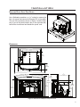
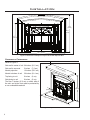
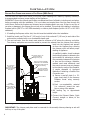
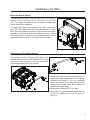
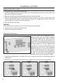
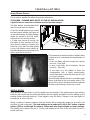
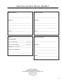
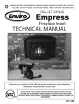
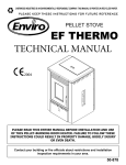
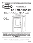
SHERWOOD INDUSTRIES IS AN ENVIRONMENTALLY RESPONSIBLE COMPANY. THIS MANUAL IS PRINTED ON RECYCLED PAPER.
PLEASE KEEP THESE INSTRUCTIONS FOR FUTURE REFERENCE
PELLET STOVE
Empress
Fireplace Insert
TECHNICAL MANUAL
Contact your building or fire officials about restrictions and installation
inspection requirements in your area.
PLEASE READ THIS ENTIRE MANUAL BEFORE INSTALLATION AND USE
OF THIS PELLET BURNING ROOM HEATER. FAILURE TO FOLLOW THESE
INSTRUCTIONS COULD RESULT IN PROPERTY DAMAGE, BODILY INJURY, OR
EVEN DEATH.
50-1386
Table of Contents
Introduction............................................................................................................3
Rating Label Location.....................................................................................3
Important Safety Data....................................................................................3
Safety Warnings And Recommendations...........................................................3
Automatic Safety Features...............................................................................4
Installation...............................................................................................................5
Removing Pellet Stove From Pallet...................................................................5
Dimensions....................................................................................................5
Clearances to Combustibles.............................................................................6
Masonry Fireplace Installation.........................................................................7
Positive Flue Connection without a Full Reline (USA Only)..................................8
Adjusting Hopper Height ................................................................................9
Installation of Cast Skirt Option.......................................................................9
Surround Panel Installation............................................................................10
Thermostat Installation.................................................................................10
Slider/Damper Setting...................................................................................11
Troubleshooting......................................................................................................12
Wiring Diagram.......................................................................................................15
Parts List................................................................................................................16
Parts Diagram - Components....................................................................................18
Parts Diagram - Parts..............................................................................................19
Warranty...............................................................................................................20
Installation Data Sheet............................................................................................23
2
Introduction
* This manual is designed for the technician in conjunction with the owner’s manual. *
RATING LABEL LOCATION:
The rating label is located on the hopper top behind the surround panel.
IMPORTANT SAFETY DATA:
Please read this entire Owner’s Manual before installing or operating this ENVIRO Pellet
Stove. Failure to follow these instructions may result in property damage, bodily injury
or even death. Contact your local building or fire official to obtain a permit and any information on
installation restrictions and inspection requirements for your area.
To prevent the possibility of a fire, ensure that the appliance is properly installed by adhering
to the installation instructions. An ENVIRO dealer will be happy to assist you in obtaining information
with regards to your local building codes and installation restrictions.
Be sure to maintain the structural integrity of the home when passing a vent through walls, ceilings, or
roofs.
The stove’s exhaust system works with negative combustion chamber pressure and a slightly positive
chimney pressure. It is very important to ensure that the exhaust system be sealed and airtight. The ash
pan and viewing door must be locked securely for proper and safe operation of the pellet stove.
Do not burn with insufficient combustion air. A periodic check is recommended to ensure proper
combustion air is admitted to the combustion chamber. Setting the proper combustion air is achieved by
adjusting the slider damper located in the front of the unit under th ash pan.
When installing the stove in a mobile home, it must be electrically grounded to the steel chassis of the
home and bolted to the floor. Make sure that the structural integrity of the home is maintained and all
construction meets local building codes.
Soot or creosote may accumulate when the stove is operated under incorrect conditions such as an
extremely rich burn (black tipped, lazy orange flames).
If you have any questions with regard to your stove or the above-mentioned information, please feel free
to contact your local dealer for further clarification and comments.
SAFETY WARNINGS AND RECOMMENDATIONS:
Caution: Do not connect to any air distribution duct or system.
Do not burn garbage or flammable fluids such as gasoline, naptha or engine oil.
Unit hot while in operation. Keep children, clothing and furniture away. Contact
may cause skin burns.
SOOT: Operation of the stove with insufficient combustion air will result in the formation of soot which
will collect on the glass, the heat exchanger, the exhaust vent system, and may stain the outside of the
house. This is a dangerous situation and is inefficient. Frequently check your stove and adjust the slider/
damper as needed to ensure proper combustion. See: “INSTALLATION - SLIDER/DAMPER SETTING”.
FLAMMABLE LIQUIDS: Never use gasoline, gasoline-type lantern fuel, kerosene, charcoal lighter
fluid, or similar liquids to start or “freshen up” a fire in the heater. Keep all such liquids well away from
the heater while it is in use.
3
Introduction
ELECTRICAL: The use of a surge protected power bar is recommended. The unit must be
grounded. The grounded electrical cord should be connected to a standard 120 volts, 60 hertz electrical
outlet and also must be accessible. If this power cord should become damaged, a replacement power
cord must be purchased from the manufacturer or a qualified ENVIRO dealer. Be careful that the electrical
cord is not trapped under the appliance and that it is clear of any hot surfaces or sharp edges. This unit’s
maximum power requirement is (4.1 Amps) 500 watts.
GLASS: Do not abuse the glass by striking or slamming the door. Do not attempt to operate the stove
with broken glass. The stove uses ceramic glass. Replacement glass must be purchased from an ENVIRO
dealer. Do not attempt to open the door and clean the glass while the unit is in operation or if glass is
hot. To clean the glass, use a soft cotton cloth and mild window cleaner, gas or wood stove glass cleaner,
or take a damp paper towel and dip into the fly ash. This is a very mild abrasive and will not damage the
glass.
SMOKE DETECTOR: Smoke detectors should be installed and maintained in the structure when
installing and operating a pellet burning appliance.
OPERATION: The ash pan and door must be closed securely for proper and safe operation of the pellet
stove. Also ensure all gaskets on the door are checked and replaced when necessary.
INSTALLATION: Be sure to maintain the structural integrity of your home when passing a vent through
walls, ceilings, or roofs. It is recommended that the unit be secured into its position in order to avoid any
displacement.
DO NOT INSTALL A FLUE DAMPER IN THE EXHAUST VENTING SYSTEM OF THIS UNIT.
DO NOT CONNECT THIS UNIT TO A CHIMNEY FLUE SERVING ANOTHER APPLIANCE.
FRESH AIR: Outside Fresh Air is optional. Consider all large air moving devices when installing your unit
and provide room air accordingly. Limited air for combustion may result in poor performance, smoking
and other side effects of poor combustion.
If you have any questions with regards to your stove or the above-mentioned information, please feel
free to contact your local dealer for further clarification and comments.
SINCE SHERWOOD INDUSTRIES LTD. HAS NO CONTROL OVER THE INSTALLATION OF
YOUR STOVE, SHERWOOD INDUSTRIES LTD. GRANTS NO WARRANTY IMPLIED OR STATED
FOR THE INSTALLATION OR MAINTENANCE OF YOUR STOVE. THEREFORE, SHERWOOD
INDUSTRIES LTD. ASSUMES NO RESPONSIBILITY FOR ANY CONSEQUENTIAL DAMAGE(S).
SAVE THIS INSTRUCTION MANUAL FOR FUTURE REFERENCE
AUTOMATIC SAFETY FEATURES:
Your pellet Stove has the following safety features:
A) The stove will shut off when the fire goes out and the exhaust temperature drops below 120 °F
(49°C).
B) The stove has a high temperature safety switch. If the temperature on the hopper reaches 200 °F
(93 °C) the auger will automatically stop and you will get a #2 flash code, and the stove will shut off
when the exhaust temperature cools. If this happens call your local dealer to reset the 200 °F (93 °C)
high limit switch. FIND THE REASONS WHY THE UNIT OVERHEATED.
C) The unit is equipped with a vacuum switch to monitor the venting and the build up of ash in the burn
pot; if either becomes blocked the vacuum switch will turn off the auger and the stove will shut off.
4
Installation
REMOVING PELLET STOVE FROM PALLET:
Use a flathead screwdriver or 5/16” socket to remove the
four (4) screws that secure the Empress FPI to the pallet.
Two (2) of the screws are shown in Figure 1 and the other
two (2) are in the same location but on the opposite side;
behind the circuit board and beside the power cord.
Figure 1: Removing Stove From the Pallet.
DIMENSIONS:
3011/16" (779mm)
2715/16" (710mm)
207/8" (530mm)
711/16"
(196mm)
151/16"
(383mm)
131/8"
(334mm)
83/4"
(222mm)
3015/16" (786mm)
42" (1067mm)
1415/16"
(379mm)
30"
(762mm)
2913/16"
(757mm)
27"
(686mm)
229/16"
(573mm)
2113/16"
(554mm)
1913/16"
(503mm)
Figure 2: Dimensions of Empress Fireplace Insert.
5
Installation
313/8"
(797mm)
289/16"
(725mm)
241/16"
(611mm)
425/8" (1083mm)
Figure 3: Dimensions of Empress Fireplace Insert with Optional Skirt.
CLEARANCES TO COMBUSTIBLES:
Refer to Figure 4.
Side wall to center of unit 24 inches (61.0 cm)
Side wall to surround
3 inches
Mantel projection
12 inches (30.5 cm)
Mantel to bottom of unit
36 inches (91.4 cm)
Top facing to unit
0 inches
(0 cm)
Side facing to unit
0 inches
(0 cm)
1 2"
(7.6 cm)
(30
.5cm
)M
antl
e
The floor 6 inches (15.2 cm) on either side of
the unit and to the front must be protected by
a non-combustible material.
36"
(91cm)
3"
(7.6cm)
24"
(61cm)
Flo
Min
6" ( or Pro
15 c
tect
i
m)
in fr on;
ont
of d
o
or
Figure 4: Empress FPI Clearance to Combustibles.
6
Installation
MASONRY FIREPLACE INSTALLATION:
If installing the Empress with a skirt
the skirt must be installed before the
installation.
Rain Cap
Steel Plate or Flashing
A non-combustible hearth pad must
cover combustible flooring underneath,
as well as 6” (150 mm) in front of the
heater and 6” (150 mm) to the side of
the heater.
Flexible or Rigid 3"
Stainless Steel Liner
1. Install the hearth pad.
Flexible stainless
steel pipe
connection
Damper Removed
or Fastened Open
2. Lock the fireplace damper in the
open position.
12" (30.5cm) Mantle
Minimum 36" (91 cm)
from Bottom of stove
3. Install a positive flue connector at
the fireplace damper.
Surround Panel
4. Set leveling leg to approximate
height.
5. Connect a Exhaust Starter Quick
Connect, straight or elbow, to the
exhaust pipe.
Optional
Exhaust Starter
Elbow (or Exhaust
Starter with
Clean-out Tee)
Min 6"
(150 mm)
Floor Protection
������� ���������
6. This fireplace insert must be installed
with a continuous chimney liner of 3”
or 4” diameter extending from the
fireplace insert to the top of the
chimney. The liner must conform
to type 3 requirements of CAN/ULC
S635.
����������� �����
Figure 5: Masonry fireplace installation without skirt.
When installing the insert into a masonry fireplace, DO NOT
remove any bricks or masonry, with the following exception:
masonry or steel, including the damper plate, may be
removed from the smoke shelf and adjacent damper frame,
if necessary, to accommodate a chimney liner. Do this only if
their removal will not weaken the structure of the fireplace
and chimney, and will not reduce protection for combustible
materials to less than that required by the national building
code. When installing the fireplace insert into a zero clearance
fireplace, DO NOT cut or modify any factory firebox parts.
Figure 6: Masonry fireplace installation with
skirt.
7
Installation
POSITIVE FLUE CONNECTION WITHOUT A FULL RELINE (USA ONLY):
This unit does not require a full reline (in USA only) when installing into a masonry fireplace, however, it
is recommended to ensure proper drafting of the appliance.
IMPORTANT: Ensure the chimney and firebox are cleaned and free of all debris, including soot and ashes,
before proceeding with this installation. If it is not clean soot maybe blown into the room through the
unit’s blower. Ensure the fireplace and chimney have not deteriorated in any way. If there is any sign of
corrosion or damage in the chimney the unit can not be installed. This unit can be installing in a masonry
fireplace built to (UBC 37 or ULC S628 standards) or a factory built fireplace (built to UL 127 or ULC S610
standards).
1. If installing the Empress with a skirt, the skirt must be installed before the installation.
2. Install the hearth pad. The floor 6” (150 mm) in front of the unit and 6” (150 mm) to each side of the
unit must be protected with a non-combustible hearth pad.
3. The vent connector from the insert must extend a minimum of 18” above the chimney seal plate.
The chimney seal plate area must be sealed to prevent the exhaust from the chimney from coming
back into the fireplace and prevent
air from the fireplace from entering
the chimney which will affect proper
drafting of appliance.
The existing chimney can
not be corroded or
damaged in any way.
Chimney must be completely
sealed with a non-combustible
material and maybe removed
annually for cleaning.
Top of vent pipe
must be 18"
(45.7cm) minimum
above the chimney
seal plate.
12" (30.5cm) Mantle
Minimum 36" (91 cm)
from Bottom of stove.
Surround Panel
A qualified installer should evaluate
the existing fireplace to determine the
best method for achieving a positive
flue connection between the vent pipe
or liner and the chimney. Whatever
method used must effectively seal
the area to prevent room air passage
to the chimney cavity of the fireplace.
A couple examples of Approved
Methods of Achieving a Positive Flue
Connection are:
a) Secure a seal-off plate (i.e. 22gage sheet steel) in the masonry
fireplace throat using masonry
screws.
b) Pack non-combustible material
(i.e. rockwool) around the vent
pipe or using a flue adapter.
Optional
Exhaust Starter
Elbow (or Exhaust
Starter with
Clean-out Tee).
Min 6"
(15.2 cm)
Floor Protection
������� ���������
����������� �����
4. Set leveling
height.
leg
to
approximate
5. Connect the Exhaust Starter Quick
Connect, straight or elbow, to the
exhaust pipe.
Figure 7: Masonry fireplace positive flue installation.
IMPORTANT: The chimney seal plate must be removed for the annually chimney cleaning as ash will
build up on top of the plate.
8
Installation
ADJUSTING HOPPER HEIGHT:
The back height of this unit can be set to one (1) of three (3)
heights; 1913/16” (503 mm), 2013/16” (529 mm), 2113/16” (554
mm). The hopper should be set to the maximum height that
can be used in the installation.
To change the height of the hopper up or down, remove the
seven (7) T-20 screws, three (3) on each side and one (1) on the
back. The screw placement is shown Figure 8. Move the hopper
assembly to the required setting and replace the screws. When
the hopper back is in place it is recommended that silicone is
used to seal the bottom lip of the hopper back and sides.
Figure 8: Screws to move hopper.
INSTALLATION OF CAST SKIRT OPTION:
The cast skirt is a five (5) piece option that can be
installed when the front of the Empress FPI is going
to be lower then the back of the unit; ensure that
none are damaged before you proceed.
Figure 9: Assembling Cast Skirt.
1. Using a 3⁄8” socket or wrench connect the five (5)
pieces of the skirt together with four (4) screws
provided (see Figure 9). Do not completely
tighten the screws; the screws should be loose
enough that the cast pieces will be able to be
adjusted but notfall apart.
2. Gently put the Empress FPI on its back.
Figure 10: Installing Cast Skirt.
3. Using two (2) screws provided attach the cast
skirt to the bottom of the unit as shown in
Figure 10.
9
Installation
SURROUND PANEL INSTALLATION:
1. Lift the cast top, it will come up and forward.
2. Install the daughter board onto the right side of the surround panel onto the two (2) studs. Fasten into
place with a wingnut on each stud.
3. Plug the wiring harness from the daugther board into the mother board.
4. Slide the surround panel behind the cast top and line up the two (2) hooks on either side on the
surround panel with the slots on either side of the Empress FPI. Wiggle the surround to ensure the
surround panel to the back of the surround pannel.
5. Push cast top back into place.
REMOVAL:
When maintenance is required on the unit the surround must be removed.
1. Lift the cast top, it will come up and forward.
2. Lift the surround panel up and out.
THERMOSTAT INSTALLATION:
Figure 11: Mother Board.
This control board can be placed into three (3)
different modes: Full Auto ON/OFF, High/Low
Thermostat or Manual Mode. From the factory
the far right AUTO pins are jumped and the
control board is in manual mode operation (see
Figure 12). If the far left AUTO pins are jumped
the circuit board is in Full Auto ON/OFF mode
(see Figure 13). When the center AUTO pins are
jumped the unit is in the HI / LOW thermostate
mode (see Figure 14), the unit will be taken to
a low or idle setting when the thermostat is
not calling for heat. When the thermostat calls
for heat, the unit will go to the setting that is
displayed on the control board Heat Indicator.
1. Install the wall thermostat in a location that is not to close too the unit but will effectively heat the
desired area.
2. Install a 12 or 24 Volt Thermostat using an 18 x 2 gauge wire from the unit to the thermostat.
Figure 12: Auto pins set-up MANUAL.
10
Figure 13: Auto pins set-up ON/OFF.
Figure 14: Auto pins set-up HI/LOW.
Installation
SLIDER/DAMPER SETTING:
This is used to regulate the airflow through the pellet stove.
THE SLIDER / DAMPER MUST BE SET AT TIME OF INSTALLATION.
A Qualified Service Technician or Installer must set the Slider Damper.
The slider damper is located behind the
cast doors and under the firebox.
• If the fire should happen to go out and
the heat output indicator has been set
on the lowest setting, the Slider Damper
should be moved to the left slightl,
lessen the air flow into the firebox.
• If, after long periods of burning, the
fire builds up and overflows the burn
pot or there is a build up of clinkers, this
would be a sign that the pellet quality
is poor, this requires more primary air,
the slider damper must be moved to the
right to give the fire more air.
Less Air
More Air
Figure 15: Slider / damper positions.
The easiest way to make sure that an efficient flame
is achieved is to understand the characteristics of
the fire.
• A tall, lazy flame with dark orange tips requires
more air – Push Right
• A short, brisk flame, like a blowtorch, has too
much air – Push Left
• If the flame is in the middle of these two
characteristics with a bright yellow/orange,
active flame with no black tips then the air is set
for proper operation.
The combustion exhaust blower is a variable speed
blower controlled by the heat output setting. This
blower will increse or decrease the blower speed as
the heat output setting is turned up or down.
Figure 16: Efficient Flame.
SPECIAL NOTES:
Pellet quality is a major factor in how the pellet stove will operate. If the pellets have a high moisture
content or ash content the fire will be less efficient and has a higher possibility of the fire building up and
creating clinkers (hard ash build-up). If this happens, move the Slider / Damper to the right slightly to
increase the air flow to the fire.
Taking a reading of vacuum pressure inside the firebox with a magnehelic gauge can be used to set
the slider for best combustion. The best settings are a reading of 0.12 to 0.13 inches of water
column (30 Pa) on the high fire setting. Some fuels may require higher or lower settings.
The reading can be taken from the 1⁄8” (3 mm) hole located on the front of the unit below the door in
the ash pan front.
11
Troubleshooting
DO NOT:
● Service the stove with wet hands. The stove is an electrical appliance, which may pose a shock hazard
if handled improperly. Only qualified technicians should deal with possible internal electrical failures.
● Do not remove from the firebox any screws without penetrating oil lubrication.
● Hold the ON / OFF BUTTON down. This is a momentary contact switch and can be damaged if held
down too long.
WHAT TO DO IF:
1. The stove will not start.
2. The stove will not operate when hot.
3. The exhaust blower will not function normally.
4. Light # 2 on Heat output bar flashing.
5. The auger motor will not function normally.
6. The 200 °F (93 °C) high limit temperature sensor has tripped.
7. The convection blower will not function normally.
8. Ignitor- the pellets will not light.
9. Control settings (Heat Level) has no effect on the fire.
10. The stove keeps going out.
*NOTE: All troubleshooting procedures should be carried out by qualified technicians or
installers.
1. The stove will not start.
üMake sure the stove is plugged in and the wall outlet is supplying power.
üPush the ON /OFF button. You may need to wait approximately 30 seconds for circuit board to initiate
before the stove will turn on.
üIf the control board has been placed in the on/off thermostat mode, then turn the thermostat up to
call for heat.
üCheck the heat level indicator. - If the # 2 light is flashing refer to section 4. Light # 2 on Heat output
bar flashing.
üCheck the fuse on the motherboard; nothing will work if the fuse is blown.
üIf the unit still does not start, contact your local service dealer for service.
2. The stove will not operate when hot.
üCheck the heat level indicator if a fire is not detected, or if the fire has gone out the #3 light will
flash because the exhaust temperature sensor’s contacts have opened.
üCheck the hopper for fuel.
üThe burn pot liner may require cleaning. Build up in the burn pot will cause the unit to shut off by
stopping the auger feed.
üIncorrect air damper setting. - Excessive air may consume the fire too quickly before the next drop of
fuel, leaving completely unburned fuel in the burn pot liner. - Insufficient air will cause build up, further
restricting the air flow through the burn pot liner. This in turn will cause the fuel to burn cold and very
slowly. Fuel may build up and smother the fire. In this case clean the burn pot. (Note: the unit may
require a change to the vent system or installation of fresh air to correct air to fuel ratio
problems).
üCheck the fuse on the motherboard; nothing will work if the fuse is blown.
üCombustion blower failure. - The combustion blower is not turning fast enough to generate the proper
vacuum in the fire box. Visual check – is the blower motor turning.
12
Troubleshooting
üCheck the exhaust blower voltage across the blower wires (>=114V on #5 setting and >= 82V on #1
setting). – Replace the Circuit Board if the Voltage reading is less than 82V. with a line voltage >115V
AC.
üCheck vacuum levels in the exhaust channel by bypassing the vacuum switch, then remove the vacuum
hose from vacuum switch. Check the vacuum readings by placing the open end of the vacuum hose on
a Magnahelic Gauge (readings must be above 0.07” W.C. (17.4 Pa) on low fire).
üPoor quality fuel – insufficient energy in the fuel to produce enough heat to keep the stove burning or
operational.
üExhaust temperature sensor failure. – Bypass sensor located on exhaust blower if stove now operates
properly, the unit may require cleaning or a new sensor. Contact your local dealer for service.
üContact your local dealer for service.
3. The exhaust motor will not function normally.
üOpen the left side access panel; check all connections against the wiring diagram.
üSee “2. The stove will not operate when hot.” Section.
4. Light # 2 on Heat output bar flashing
(The 200 °F ( 93 °C) high limit temperature sensor has tripped.)
üReset sensor and determine cause – was it a convection blower failure? Test by connecting it directly
to power.
To reset Circuit Board after a trouble code - push the ON/OFF button
5. The auger motor will not function normally.
üThe burn pot liner may require cleaning. Build up in the burn pot will cause the unit to shut off.
üCheck for obstructions in the hopper system.
üEnsure door is closed and ash pan is closed. The auger motor will stop if there is not enough vacuum
in the stove.
üPinch, break or blockage in vacuum hose - check hose for pinch points or damage, replace or re-route
as required. Blow out vacuum hose
üBlocked exhaust / venting system - have stove and venting cleaned and inspected.
üSevere negative pressure in area where unit is installed - check the operation by opening a window,
does this solve the problem? If it does, install fresh air intake to unit or room. Venting system may
require vertical section to move termination into a low pressure zone.
üVacuum switch failure - bypass the vacuum switch, if this corrects the problem check for above problems
before replacing the vacuum switch.
üDamage to orange wires between circuit board and vacuum switch - inspect wires and connectors
üCombustion blower failure - the combustion blower is not turning fast enough to generate the proper
vacuum in the exhaust channel. Visual check; is the blower motor turning? Check the exhaust blower
voltage across the blower wires (>=114V on #5 setting and >= 82V on #1 setting). – Replace the
circuit board if the Voltage reading is less than 82V. with a line voltage >114V AC.
üCheck vacuum levels by bypassing the vacuum switch, then remove the Vacuum hose from Vacuum
Switch. Check vacuum readings by placing the open end of the Vacuum Hose on a Magnahelic Gauge.
(readings must be above .07” W.C. on low fire).
üCall your local dealer for service.
13
Troubleshooting
Auger light flashes but auger motor does not turn at all.
üIf the auger gear box does not turn but the motor’s armature does try to spin then the auger is jammed.
– Try to break apart jam by poking at the jam through the drop tube. If this fails then empty the hopper
and remove the auger cover **remember to re-seal the cover after installation**
üCheck the fuse on the motherboard; nothing will work if the fuse is blown.
6. The convection blower will not function normally.
üClean all grill openings at the back and below unit as well as the fan blades.
üContact your local dealer for service.
7. Ignitor- the pellets will not light.
(Everything else in the stove operates but the ignitor will not light the pellets.)
üMake sure the burn pot liner is up tight and square to the ignitor tube by pushing the burn pot back
against the ignitor tube.
üCheck to see if the exhaust blower is operating. If not, contact your local dealer for service.
NOTE: The ignitor should be bright orange in color after about five (5) minutes. If not replace the
ignitor.
8. Control settings (Heat Level) has no effect on the fire.
üNote: If the system light is flashing the control board has complete control of the unit. When the units
system light becomes solid then control of the unit is given back to the operator.
üIf there is no control of the heat level button make sure the thermostat is calling for heat.
üCall your local dealer for service.
9. The stove keeps going out.
a) If the stove goes out and leaves fresh unburned pellets or cigarette-like ashes in the burn pot liner,
the fire is going out before the stove shuts off.
üCheck Ash build-up in the burn pot can make the auger stop. Increase the air by moving the slider to
the right.
üCheck to see that the slider / damper is in the correct position.
üTurn the heat level up slightly (poor quality pellets will require slightly higher settings).
üSet the auger trim till the #1 and #5 lights are illuminated.
b) If the stove goes out and there are partially burned pellets left in the burn pot liner, the stove has shut
down due to a lack of air, exhaust temperature, or power failure.
üAdjust the slider / damper.
üCheck to see if the stove needs a more complete cleaning.
üTurn the heat level up slightly (poor quality pellets will require slightly higher settings).
üDid the power go out?
üContact your local dealer for service.
14
Wiring Diagram
Orange
Orange
Vacuum
Switch
Blue
Combustion
Blower
Daughter Board
Red
Connect
Thermostat
Here
White
Red
Brown
120oF (49oC)
Exhaust
Temperature
Sensor
Ground
Power
Cord
Brown
Black
Black
Red
White
115V
White
220V
Blue
Common
Thermostat
Selector Pins
115V
Black
220V
Brown
Hot
Mother Board
Ignitor
Convection
Blower
Purple
White
Auger
Motor
200oF (93oC)
High Limit
Temperature
Sensor
Yellow
White
Black
White
Grey
Grey
Purple
Blue
Yellow
Red
Orange
Orange
Brown
Brown
Grey
Grey
15
Parts List
Reference
Number
1
2
3
4
5
6
7
8
9
10
11
12
13
14
16
Description
120 °F (49 °C) Ceramic Fan Temperature Sensor
Domestic Power Cord - 115V
Auger Motor - 115V
High Limit Temp Sensor 200 °F (93 °C) Manual Reset
Silicone Hose
Ash Pan Latch
Pellet Stove Cleaning Brush
Convection Blower - 115V
Door Screen
Brick Panel Retainers (set of 2)
Door Knob - Brushed Nickel
Combustion/ Exhaust Blower - 115V
400 Watt Ignitor - 115V
Dual bulb door gasket - 10 ft (3.05m)
Hinge Pin - Silver
Circuit Board 5 Amp Fuses - 115V (Pair)
5⁄8“ ID Auger Collar with Screw
Auger - 115 V
Auger Plate with Bushing
Burn Pot - 1.5” Intake Hole
Empress FPI Domestic Owner’s Manual - 115V
Empress FPI Domestic Technical Manual - 115V
Vacuum Switch - Low Preasure
Part
Number
EC-001
EC-042
EF-001
EF-016
EF-018
EF-060
EF-156
EF4i-002
50-177
50-185
50-262
50-473
50-619
50-634
50-750
50-833
50-968
50-1346
50-1359
50-1366
50-1385
50-1386
50-1390
Parts List
Reference
Number
15
16
17
18
19
20
21
22
23
24
25
26
27
28
29
29
29
30
30
30
31
32
32
32
Description
Exhaust Starter Tube 3” Quick Connect
Mother Board - 120V
Daughter Board - 120V
Slider Damper & Lever
Exhaust Starter Elbow Quick Connect
Exhaust Starter Gasket
Daughter Board Decal
Ignitor & Intake Tube
Cast Brick Panel Set
Inner Door Complete with Glass & Tape
Burn Pot Liner with Sides
Door Bolt, Hardened Bushing & Nut
Inner Door Handle
Glass With Tape
Empress FPI Cast Surround Panel - Painted
Empress FPI Cast Surround Panel - Diamond Black
Empress FPI Cast Surround Panel - Antique Chestnut
Empress FPI Cast Skirt - Painted
Empress FPI Cast Skirt - Diamond Black
Empress FPI Cast Skirt - Antique Chestnut
Empress FPI Oversized Filler Surround Panel
Empress FPI Casting Complete - Painted
Empress FPI Casting Complete - Diamond Black
Empress FPI Casting Complete - Antique Chestnut
Part
Number
50-1391
50-1392
50-1393
50-1394
50-1395
50-1396
50-1397
50-1398
50-1399
50-1400
50-1401
50-1465
50-1467
50-1468
50-1258
50-1260
50-1261
50-1262
50-1264
50-1265
50-1348
50-1403
50-1404
50-1405
17
Parts Diagram - Components
Empress - Fireplace Insert Components
October 2006
3
1
11
21
17
16
10
5
12
14
18
8
2
9
20
18
4
October 2006
Empress - Fireplace Insert Parts
15
19
31
29
22
13
25
30
32
6
23
28
24
26
7
27
Parts Diagram - Parts
19
Warranty
Sherwood Industries Ltd. is the manufacturer of the Enviro line of heating products. At Sherwood
Industries, our commitment to the highest level of quality and customer service is the most important
thing we do. Each Enviro stove is built on a tradition of using only the finest materials and is backed by
our Exclusive Lifetime Limited Warranty to the original purchaser. With Enviro, you’re not just buying a
stove, you’re buying a company with years of unequalled performance and quality.
Limited Lifetime Warranty:
Under this warranty, Sherwood Industries Ltd. covers the fireplace or stove body and accessories
against defects in materials and workmanship, for part repair or replacement for the first seven (7)
years and limited labour for the first two (2) years to the original purchaser. This Warranty covers:
Firebox, Heat Exchanger, Burn Pot, Firebox Panels, Ceramic Glass, Pedestals, Panels, Legs, Log Sets
and Door Assembly. Please see the exclusions and limitation section below as certain restrictions and
exclusions apply to this warranty.
Limited Three (3) Year Warranty
Under this warranty, Sherwood Industries Ltd. covers the Burn Pot Liner against defects in materials
and workmanship, for part repair or replacement for the first three (3) years and limited labour for the
first two (2) years to the original purchaser. Please see the exclusions and limitation section below as
certain restrictions and exclusions apply to this warranty.
Limited Two (2) Year Warranty:
Under this warranty, Sherwood Industries Ltd. covers: Ignitor, Auger Motor, Circuit Board, Timers, Temp
Sensors, Blowers, Vacuum Switch and Wire Harness, against defects in materials and workmanship, for
part repair or replacement for the first two (2) years and limited labour for the first two (2) years to
the original purchaser. Please see the exclusions and limitation section below as certain restrictions and
exclusions apply to this warranty.
Limited One (1) Year Warranty:
Under this warranty, Sherwood Industries Ltd. covers all exterior surface finishes against defects in
materials and workmanship, for part repair or replacement and limited labour for the first (1) year to
the original purchaser. Please see the exclusions and limitation section below as certain restrictions and
exclusions apply to this warranty.
Here is how our Warranty works
If you have any concerns with your Enviro product please contact the dealer where you purchased the
fireplace or stove. Your dealer shall make all claims under this warranty in writing.
To the Dealer
When filling out a warranty claim please complete the following information on an official warranty claim
form:
Customer information: Name, address and telephone number of purchaser and date of purchase.
Dealer information: Date of installation, name of installer and dealer, serial number of the appliance,
nature of complaint, defects or malfunction, description and part numbers of any parts replaced.
To the Distributor
Sign and verify that work and information are correct.
20
Warranty
Exclusions and Limitations:
1. This Warranty does not cover tarnish, discoloration or wear on the plating or paint.
2. This Warranty excludes wear and tear or breakage caused by cleaning, moving or service on log set.
3. A qualified installer must install this stove or fireplace. This Limited Warranty covers defects in materials
and workmanship only if the product has been installed in accordance with local building and fire codes;
in their absence, refer to the owner’s manual. If the product is damaged or broken as a result of any
alteration, willful abuse, mishandling, accident, neglect, or misuse of the product, the Limited Warranty
does not apply.
4. The stove must be operated and maintained at all times in accordance with the instructions in the
Owner’s Manual. If the unit shows signs of neglect or misuse, it is not covered under the terms of this
Warranty policy. Performance problems due to operator error will not be covered by the Limited Warranty
policy.
5. As this is a heating appliance some changes in colour of surface finishes may occur. This is not a flaw and
as such is not covered under this warranty.
6. Some minor expansion, contraction, or movement of certain parts and resulting noise, is normal and not
a defect and, therefore, is not covered under this Limited Warranty.
7. Misuse includes over-firing. Over-firing this appliance can cause serious damage and will nullify the
Limited Warranty.
8. The Limited Warranty will cover glass thermal breakage only and will not cover misuse of the stove glass,
including but not limited to glass that is struck, has surface contaminates or has had harsh or abrasive
cleaners used on it.
9. This warranty does not cover products made or provided by other manufacturers and used in conjunction
with the operation of this stove without prior authorization from Sherwood Industries Ltd. The use of
such products may nullify the Limited Warranty on this stove. If unsure as to the extent of this Limited
Warranty, contact your authorized Enviro dealer before installation.
10. Sherwood Industries Ltd. will not be responsible for inadequate performance caused by environmental
conditions.
11. The Limited Warranty does not cover installation and operational related problems such as spillage
caused by environmental conditions. Environmental conditions include but are not limited to nearby
trees, buildings, roof tops, wind, hills, mountains, inadequate venting or ventilation, excessive offsets,
negative air pressures or other influences caused by mechanical systems such as furnaces, fans, clothes
dryers etc.
12. The Limited Warranty is void if:
a) The stove has been operated in atmospheres contaminated by chlorine, fluorine or other damaging
chemicals.
b) The stove is subject to submersion in water or prolonged periods of dampness or condensation.
c) Any damage to the unit, combustion chamber or other components due to water, or weather damage
which is the result of, but not limited to, improper chimney/venting installation.
c) Salt air in coastal areas or high humidity can be corrosive to the finish; these environments can cause
rusting. Damage caused by salt air or high humidity is not covered by the Limited Warranty.
13. Exclusions to the Limited Warranty include: injury, loss of use, damage, failure to function due to
accident, negligence, misuse, improper installation, alteration or adjustment of the manufacturer’s
settings of components, lack of proper and regular maintenance, alteration, or act of God.
14. The Limited Warranty does not cover damage caused to the fireplace or stove while in transit. If this
occurs, do not operate the stove and contact your courier and/or dealer.
15. The Limited Warranty does not extend to or include firebox paint, door or glass gaskets with damage
caused by normal wear and tear, or exterior paint discoloration or chipping, worn gaskets, etc.
16. The Limited Warranty does not include damage to the unit caused by abuse, improper installation, or
modification of the unit.
21
Warranty
17. Damage to plated surfaces caused by fingerprints, scratches, melted items, or other external scores and
residues left on the plated surfaces from the use of abrasive cleaners or polishes is not covered in this
warranty.
18. The Limited Warranty does not cover tarnish, discoloration or wear on the plated surfaces.
19. The paint on the Metal Brick Liner may peel. This is due to the extreme conditions applied to the paint
during normal usage. It is not a flaw and is not covered under warranty.
20. Sherwood Industries Ltd. is free of liability for any damages caused by the fireplace or stove, as well as
inconvenience expenses and materials. The Limited Warranty does not cover incidental or consequential
damages.
21. The Limited Warranty does not cover any loss or damage incurred by the use or removal of any
component or apparatus to or from the Enviro fireplace or stove without the express written permission
of Sherwood Industries Ltd. and bearing a Sherwood Industries Ltd. label of approval.
22. Any statement or representation of Enviro products and their performance contained in Enviro
advertising, packaging literature, or printed material is not part of the Limited Warranty.
23. The Limited Warranty is automatically voided if the fireplace or stove’s serial number has been removed
or altered in any way. If the stove is used for commercial purposes, it is excluded from the Limited
Warranty.
24. No dealer, distributor, or similar person has the authority to represent or warrant Enviro products beyond
the terms contained within the Limited Warranty. Sherwood Industries Ltd. assumes no liability for such
warranties or representations.
25. Sherwood Industries Ltd. will not cover the cost of the removal or re-installation of the stove, hearth,
facing, mantels, venting or other components.
26. Labour to replace or repair items under this Limited Warranty will be covered per our warranty service
fee reimbursement schedule. Labour rates are set per component and as such total labour costs may
not be covered.
27. Sherwood Industries Ltd. is not liable for freight or labour on any stove replaced in-field and is not liable
for travel costs for service work. In the event of in-home repair work, the customer will pay any in-home
travel fees or service charges required by the Authorized Dealer.
28. At no time will Sherwood Industries Ltd. be liable for any consequential damages which exceed the
purchase price of the unit. Sherwood Industries Ltd. has no obligation to enhance or modify any stove
once manufactured (example: as a stove evolves, field modifications or upgrades will not be performed).
29. This Limited Warranty is applicable only to the original purchaser and it is non-transferable.
30. This warranty only covers Enviro products that are purchased through an authorized Enviro dealer.
31. If for any reason any section of the Limited Warranty is declared invalid, the balance of the warranty
remains in effect and all other clauses shall remain in effect.
32. The Limited Warranty is the only warranty supplied by Sherwood Industries Ltd., the manufacturer
of the stove. All other warranties, whether express or implied, are hereby expressly disclaimed and
purchaser’s recourse is expressly limited to the Limited Warranty.
33. Sherwood Industries Ltd. and its employees or representatives will not assume any damages, either
directly or indirectly, caused by improper usage, operation, installation, servicing or maintenance of this
stove.
34. Sherwood Industries Ltd. reserves the right to make changes without notice. Please complete and mail
the warranty registration card and have the installer fill in the installation data sheet in the back of the
manual for warranty and future reference.
35. Sherwood Industries Ltd. is responsible for stocking parts for a maximum of seven (7) years after
discontinuing the manufacture or incorporation of the item into its products. An exception to this would
be if an OEM supplier is not able to supply a part.
22
Installation Data Sheet
The following information must be recorded by the installer for warranty purposes and future reference.
NAME OF OWNER:
NAME OF DEALER:
_________________________________________
_________________________________________
ADDRESS:
ADDRESS:
_________________________________________
_________________________________________
_________________________________________
_________________________________________
_________________________________________
_________________________________________
PHONE:___________________________________
PHONE:___________________________________
MODEL:___________________________________
NAME OF INSTALLER:
SERIAL NUMBER:___________________________
DATE OF PURCHASE: _____________
_________________________________________
(dd/mm/yyyy)
DATE OF INSTALLATION:___________(dd/mm/yyyy)
ADDRESS:
MAGNEHELIC AT INSTALL:___________________
_________________________________________
INSTALLER’S SIGNATURE:
_________________________________________
_________________________________________
_________________________________________
PHONE:___________________________________
MANUFACTURED BY:
SHERWOOD INDUSTRIES LTD.
6782 OLDFIELD RD. SAANICHTON, BC, CANADA V8M 2A3
www.envirofire.biz
October 30, 2006
C-11193
23