1
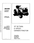
8EA/RS
OWNERS
MANUAL
Caution:
Read Rules for
Safe Operation
and Instruction s
Carefully
GT 18 TWIN
TRACTOR
Assembly
Installation
Operation
Repair Parts
Sears, Roebuck and Con,Chicago, IL 60684 U.S_A.
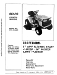
CONGRATULATIONS
on your purchase of a Sears GT 18
Garden Tractor° It has been designed, engineered and manufactured to give you dependability and performance. Should
you experience any problem you cannot easily remedy,
please contact your nearest Sears Service Center. They have
competent, well-trained technicians and the proper tools and
parts to service or repair this unit.
MODEL
NUMBER,
SERIAL
NUMBER,
THE MODEL AND SERIAL
FOUND
ON THE MODEL
TO THE DRAWBAR,
Please read and retain this manual° The instructions will enable
you to assemble, operate and maintain your' Tractor properly. Always observe the "RULES FOR SAFE OPERATION".
YOUR
NEW
GARDEN
NUMBERS WILL BE
PLATE ATTACHED
YOU SHOULD
RECORD BOTH MODEL
AND
SERIAL NUMBERS AND KEEP IN A SAFE PLACE
FOR FUTURE REFERENCE=
GT 18
TRACTOR
FEATURES...
CRAFTSMAN
18 H.P. TWIN-CYLINDER
ENGINE-cootrunning performance and long life with plenty of power- to
take on a variety of yard, gardening or snow removal tasks,
ATTACHMENT
VERSATILITY*-handIes
a large variety of
Sears Yard and Garden Tractor Attachments including _ o o
44 INCH MOWER with three "high-lift"
blades to stand
grassup for level cuts.
OTHER SOIL TILLAGE
ATTACHMENTS
including Plow,
Disc Harrow, Drag Harrow and Cultivator.
46 INCH DOZER
or
INTERLOCK
SWITCH SYSTEM--allows engine to start only
when tractor Clutch-Brake Pedal is depressed and Attachment
Clutch Switch is in "OFF" position.
, _jr
r_rnoves snow.
powdery
ALL GEAR TRANSMISSION-six
speedsforward, two reverse _.
(_.INCH
SNOW
speeds--to let you select the proper match for the terrain and
snow with ease..
tile job. Automotive-type
differential helps guard against turf
REAR GRADER
AND LEVELER
BLADE levels new
scuffing_
yards, grading lanes, driveways and parking areas,
CONTROL PANEL-wlth
Throttle, Choke, Light Switch, Ignition Switch, Ammeter, Parking Brake Lever and C_utch
Swltch--conveniently grouped for ease of use.
LIMITED
ON
ONE
ELECTRIC
YEAR
START
WARRANTY
RIDING
EQUIPMENT
For one year from date of purchase, when this ridinq equipment is maintained, lubricated, and tuned up according to the
operating and maintenance instructions in the owner s manual, Sears will repair free of charge any defect in material or'
workmanship in this electric start riding equipment.
This warranty excludes blade(s), blade adapter(s),
worn during normal use°
This warranty
spark plug(s), air cleaner and belt(s), which are expendable and become
does not cover:
tire replacement or repair caused by punctures from outside objects (such as nails, thorns, stumps, or glass);
and
repairs necessary because of operator abuse or- negligence, including the failure to maintain the equipment
according to instructions contained tn the owner s manual; and
riding equipment used for commercial or rental purposes.
FULL
SO-DAY
WARRANTY
ON
BATTERY
For 90 days from the date of purchase, if any battery included with this riding equipment provesdefective in material or
workmanship and our testing determines the battery will not hold a charge_Sears will replace the battery at no charge.
WARRANTY
SERVICE iS AVAILABLE
BY CONTACTING
THE NEAREST SEARS SERVICE CENTER/DEPARTMENT IN THE UNITED STATES, This warranty applies only while this product is in use in the United States.
This warranty gives you specific legal rights, and you may also have other rights which vary from state to state.
Seam, Roebuck and Co., D/698-731A, Sears Tower,Chicago,/L 60684
-2-
TABLE
RULES FOR SAFE OPERATION
ASSEMBLY
OPERATION
INSTRUCTIONS
INSTRUCTIONS
........
OF CONTENTS
BELOW
.................
................
RULES
MAINTENANCE
INSTRUCTIONS
4
TROUBLE
7
REPAIR PARTS ...........................
FOR SAFE
1_ Know the controls
and how to stop quickly.
READ THE
OWNERIS
MANUAL.
2. Do- not allow children to operate the vehicle. Do not allow
adults to operate
it without
proper
instruction
or without having read the owners manual.
3. Do not carry passengers. Keep children
and pets a safe distance away_
4. Always wear substantial
footwear,,
Do not wear loose fitting
clothing
that could get caught in moving parts°
5. Keep your eyes and m nd on your tractor,
mower and the
,
"
area being
cut. Don It let other "interests d_stract
yo.,U
6o Do not attempt
to operate your tractor
or mower when
not in the drivers seat.
7. Always
get on or off your tractor
from the operators
left
hand side.
8. Clear the work area of obiects which might be picked up
and thrown,
9. Disengage
all attachment
clutches
before
attempting
to
start the engine,
10 Disengage
power to attachments
and stop the engine before leaving the operator s position.
11o Disengage power to mower,
stop the engine and disconnect
spark plug wire(s) from spark plug(s) before cleaning, making an adjustment
or repairs
12 Disengage
power to attachments
when transporting
or not
in use°
13 Take all possible precautions
when leaving the vehicle unattended,
[Jisengage the power-take=off,
lower the attachments,
return
drive
control
lever to neutral,
shift
into
neutral,
set the parking brake, stop the engine and remove
the key
14. Do not stop or start suddenly
when going uphill or downhill. Mow up and down the face of slopes (not greater than
15°); never across the face, Refer to page 47.
15. Reduce speed on slopes and make turns gradually
to prevent tipping
or loss of control
Exercise extreme
caution
when changing direction
on slopes°
16., While going up or down slopes, place Gear S,bift Control
Lever in 1st gear and Range Shift Lever in "'LO"
(Low)
position
to negotiate the slope without
stopping,
17_ Never mow in wet or slippery
grass, when traction
is unsure or at a speed which could cause a skid.
18o Stay alert for holes in the terrain and other hidden hazards,
19. Do not drive too close to creeks, ditches and public highways,,
20° E_tercise special care when mowing
around
fixed objects
in order to prevent
the blades from striking
them
Never
deliberately
run tractor
or mower into or over any foreign
object.
21,, Never shift gears until tractor
comes to a stop,
22., Never place hands or feet under the mower,
in discharge
chute or near any moving parts while tractor or mower are
running.
Always keep clear of discharge chute,
23,
SHOOTING
.............
13
.....................
25
27
OPERATION
Use care when pulling loads or using heavy eqUipment_
a. Use only approved drawbar
hitch points.
b Limit loads to those you can safely control.
c, !_o not turn sharply_ Use care when backing°
d.
24.
25,,
26.
27°
28.
29.
30.
31o
32°
33.
34,
35.
36,
37.
Use counterweight
or wheel weights when suggested in
the owner s manual.
Watch out for traffic when crossing or near roadways,_
When
using any attachments,
never direct
discharge
of
material
toward
bystanders
nor allow anyone near the vehicle while in operation,
Handle gasoline with care - it is highly flammable,
a. Use approved
gasoline containers.
b. Never remove the cap of the fuel tank or add gasoline to
a running
or hot engine, or fill the fuel tank indoors.
Wipe up spilled gasoline.
co Open doors if the engine is run in the garage - exhaust
fumes are dangerous.
Do not run the engine indoors,
Keep the vehicle and attachments
in good operating
condition,
and keep safety devices in place°
Keep all nuts, bolts and screws tight to be sure the equipment is in safe working
condition.
Never store the equipment
with gasoline in the tank inside
a building
where fumes may reach an open flame or spark°
Allow the engine to cool before storing in any enclosure.
To reduce fire hazard, keep the engine free of grass, leaves
or excessive grease. Do not clean product
while engine is
running.
Except
for
adjustment;
DO NOT operate
Engine
if air
cleaner
or cover directly
over carburetor
air intake is re=
moved. Removal of such part could create a fire hazard_
Do not operate without
a muffler
or tamper with the exhaust system,
Damaged
mufflers
or spark arresters could
create
a fire hazard.
Inspect
periodically
and replace
if
necessary.
The vehicle
and attachments
should be stopped
and inspected for damage after striking
a foreign
object and the
damage should be repaired before restarting
and operating
the equipment,
Do not change the engine governor
settings
or overspeed
the engine; severe damage or injury may result.
When using the vehicle with
mower,
proceed
as follows;
a. Mow only in daylight
or in good artificial
light.
b. Shut the engine off when unclogging
chute,
co Check the blade mounting
bolts for proper tightness at
frequent
intervals,,
Do not operate the mower without
the deflector
shield in
place.
Disengage power to mower before backing up. Do not mow
in reverse unless absolutely
necessary and then only after
careful observation
of the entire area behind the mower
LOOK FOR THIS SYMBOL TO POINT OUT IMPORTANT SAFETY
PRECAUTIONS.
IT MEANS - ATTENTION!
BECOME ALERT!
YOUR SAFETY IS INVOLVED.
WARNING
This
unit
is equipped
with
an internal
combustion
•
engine and should not be used on or near any unimproved
forest-covered,
brush
f
covered or grass-covered
land unless the engine s exhaust system is equipped with
laws (if any). If a spark arrester is used, it should be maintained
in effective working
a spark arrester meeting
order by the operator.
applicable
local or state
In the State of California the above is required by law (Section 4442 of the California Public Resources Code). Other states may
have similar laws. Federal laws apply on federal lands, See your Authorized Service Center for spark arrester muffler part number
106664X.
-3 -
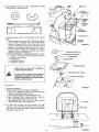
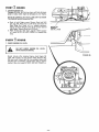
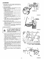
ASSEMBLY
CUT
AWAY
VIEW
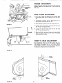
VENT
To assemble and adjust your Tractor
CAP
two 7/16"
wrench
you will need:
wrenches, one 3/4" wrench and one 9/16"
NOTE: RIGHT HAND (R.H_) AND LEFT HAND (LH.) ARE
DETERMINED
FROM OPERATOR'S
POSITION WHILE
SEATED ON THE TRACTOR
TUBE
1. Remove Fasteners holding Tractor and Mower Deck to skid.
Also remove Battery, Steering Wheel and Bag of Parts.
BATTERY
CELL
WEAR EYE AND FACE SHtELD_
FIGURE
WASH HANDS OR CLOTHING
IMMEDIATELY tF ACCIDENTALLY
IN CONTACT
WITH ELECTROLYTE°
1
DO NOT SMOKE, FUMES FROM CHARGED ELECTROLYTE
ARE EXPLOSIVE.
BATTERY
COMPARTMENT
2. Fill and charge Battery (before installing)° NOTE: SEE
DETAILED
INSTRUCTIONS
PACKAGED
WITH BATTERY.
a,, Fill Battery with electrolyte to bottoms of tubes in cells
(Fig. 1). NOTE: DO NOT OVERFILL.
OVERFILLING
WILL RESULT IN DAMAGE TO TRACTOR.
b. Check level of electrolyte after 30 minutes, Add additional electrolyte if necessary. NOTE: TIGHTEN VENT
CAPS SECURELY,
c. Charge Battery at a iate not exceeding three amperes
for about two and one half hours,.
d_ Neutralize excess electrolyte for disposal by adding it
to four inches of water in a five gallon plastic container_ Stir with a wooden or plastic paddle while adding
baking soda until the addition of more soda causes no
more foaming
GRILL
DO NOT SHORT BATTERY
TERMINALS°
BEFORE METAL
INSTALLING
BATTERY,WRIST=
REMOVE
BRACELETS,
WATCH
BANDS,
RINGS, ETC= FROM
YOUR PERSON.
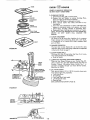
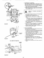
FIGURE 2
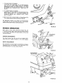
3. Install Battery.
a. L_ift hood from rear sides (Figo 2),,
b_ Remove tape from Plastic Tray. Make sure Drain Tube
(Fig_ 3) is fastened to Drain Hole in Battery Tray and
Battery Tray is positioned in hole of Battery Support.
c= Flace Battery in Plastic Tray (Battery Terminals to front
of Tractor ) (Fig, 3)_
klUT
HER
4_ Connect
Battery
Cables using: two
Washers, two Lockwashers
and two
size below) found in Bag of Parts,
Hex Bolts, two
Hex Nuts (shown
Fiat
full
HEX
BOLTS
BLACK
(NEGATIVEI
CABLE
FROM ACCIDENTAL
FIGURE 3
-4-
GROUNDING,
°°°"
t
ao Connect RED Battery Cable to Positive (+) Battery Terminal with Hex Bolt, Flat Washer, Lockwasher and Hex
Nut (Fig° 3)° Tighten securely_
b_ Connect BLACK Ground Cable to Negative (-) Battery
Terminal with remaining Hex Bolt, Flat Washer, Lockwasher and Hex Nut (Fig,, 3}_ Tighten securety_
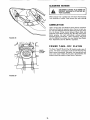
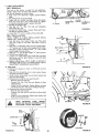
5o Install Battery using: two Int./Exto Lockwashers, two Wing
Nuts {shown full size below) and
INTJEXT.
LOCKWASHER
WING
NUT
WING NUT
tNTJEXT,
LOCKWASHER
ACCESS
DOOR
TERMINAL
GUARD
TERMINAL
ACCESS DOOR
BATTERY
two Battery
Parts.
Bolts
and one Terminal
Guard
found
BOLT
in Bag of
BATTERY
SUPPORT
a, Using the square hole on one side of the Battew
Support
(Fig, 4") insert one Battery
Bolt,
head of Bolt down°
Fasten the Battery
Bolt to the Terminal
Guard using
into/Exto Lockwasher
and Wing Nut as shown in Fig. 4.
b. Assemble
the remaining
Battery
Bolt to other side of
Battew
Support and fasten Terminal
Guard to it with remaining
lnt./Exto
Lockwasher
and Wing Nut_ Tighten
Wing Nuts securely by hand (Fig° 4).
NOTE:
USE TERMINAL
ACCESS DOORS (FIG 4) FOR:
1. Inspection
for secure conne_tlons
(tighten
hardware)..
2. Inspection
for corrosion.
FIGURE 4
HEX WASHER HEAD BOLT
LOCKWASHER
3. Testing battery..
4,_ ,Jumping (if required}.
5. Charging {if requiredL
ASHER
STEERING
WHEEL
WHEN NOT IN USE, KEEP TERMINAL
ACCESS DOORS CLOSED.
WHEEL
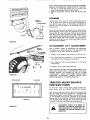
DO NOT START ENGINE UNTIL MOWER
SUSPENSION BRACKET HAS BEEN RELEASED° SEE MOWER AND DRIVE BELT
INSTALLATION,
PAGE 8.
INSERT
STEER,NO
COLUMN
6. Close Hood.
FIGURE
7.
Install Steering Wheel.
NOTE: POSITION
FRONT WHEELS
FORWARD,
a. Remove
Hex Washer Head Bolt, Lockwasher
and Large
Washer from Steering Column
(Fig_ 5)°
bo Position Steering Wheel over Steering Wheel Insert
c. S_ecure Steering
Wheel to Steering
Cotumn
using Hex
Bolt, Lockwasher
and Large Washer (Figr 5).
do Snap Steering
Wheel Cap in place on Steering Wheel.
Steering Wheel Cap found in Bag of Parts.
SEAT
8. To adjust seat position, pivot seat forward.
Use 3/4"
wrench to loosen Seat Bolt and stide seat to desired position. Make sure seat sets straight on Seat Pan and tighten
Seat Bolt securely (Fig° 6)°
PAN
SEAT BOLT
/
-5_
5
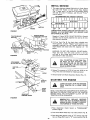
8NUTIIAL
SERVICE
1. This engine hag been shipped filled
Oil Level with Tractor on level
(Fig, 7) clean, push it in tight for
and read Oil Level. If necessary,
mark is reached,
RECOMMENDED
with oil. Check Engine
ground., Wipe Dipstick
a few seconds, remove
add Oil. until. , FULL t_
SAE VISCOSITY
GRADES
I I I J 1301
I.J_LJ_-L--1
DIPSTICK
-20°
ENGINE
0°
32 °
60 °
80 °
100 °
TEMPERATURE
RANGE EXPECTED BEFORE NEXT OIL
CHANGE, ALL OILS MUST MEET A.Po/. SERVICE CLASStFICATION SD, SE, OR SF.
FIGURE7
PARKING
BRAKE
"ENGAGED"
POSITION
"CLUTCH/BRAKE"
POSITION
Capacity is 3 pints. NOTE:
assembly
must be securely
when engine is operating°
DO NOT OVERFfLL
tightened
into tube
2, Fitl Fuel Tank (Fig, 6)r, Use fresh, clean, unleaded auto,
mot ve gasol ne_ (Leaded
Regular grade gasoline is an
acceptable substitute, but will increase carbon and lead
oxide deposits and reduce valve tife)_ Capacity is 3 - 1/2
gallons_
.
ct
"CLUTCH" POSITION
BRAKE
Dipstick
at all times
II
.
I
WARNING: DO NOT USE GASOHOL OR METHANOL.
These type fuels react with water content in the fuel
and tend to form strong acids which can corrode metal
parts and harm rubber and plastics,,
SHAFT
FIGURE 8
FILL TO BOTTOM OF GAS TANK FILLER NECK° DO NOT OVERFILL,
WIPE
OFF ANY SPILLED OIL OR FUEL. DO
NOT STORE, SPILL OR USE GASOLINE
NEAR AN OPEN FLAME.
ATTACHMENT
IGI_
KEY
_'HRDTTLE
CONTROL
3, Reduce Tire pressure to 14 PSI in front and t0 PSI in rear'
Tires, (Tires were overinflated for' shipping purposes),
CHOKE
4, Remove bands from Mower Suspension Bracket (Fig. 11),
PARKING
BRAKE
STARTING
[
_!_
THE
ENGgNE
YOUR TRACTOR
IN A LARGE,
LEARNTOSTART,STOPANDREVERSE
AREA.
OPEN
"RANGE
IFT
LEVER
GEAR SHIFT
CONTROL LEVER
NOTE: THIS TRACTOR IS EQUIPPED WITH INTER LOCK
SWITCHES TO PREVENT STARTING OF THE TRACTOR
ENGINE WHILE THE ATTACHMENT
CLUTCH OR THE
TRACTOR CLUTCH IS ENGAGED.
FIGURE 9
IMMEDIATELY
THAT ARE NOT
ORDER. DO NOT
THE PURPOSE OF
1, Place Attachment
position (Fig. 9),
2. Push Clutch-Brake
Clutch
REPLACE
SWITCHES
IN PROPER WORKING
ATTEMPT TO DEFEAT
THESE SWITCHES.
Switch
in
"DISENGAGED"
Pedal fully into brake position (Fig. 8),
Place Gear Shift Control Lever- in "N" neutral, start position and Range Shift Lever in "N" neutral posltion (Fig. 9)o
4. PullChokeout(Fig.9).
5 Move
ThrottleControltomiddleposition
(Fig°9)o
OUT
THEOPERATE
DEFLECTOR
SHIELDWITH1N
DO NOT
THE MOWER
PLACE.
6.TurnIgnitionKeyto "START"position
untilEngine
starts
(Fig,9). NOTE:DONOTRUNSTARTER
CONTINUOUSLYFORMORETHANFIFTEEN
SECONDS
PER
MINUTE°If engine
doesnotstartafterseveral
attempts,
moveThrottleControlto "F" (fast)position,waitafew
minutes
andtry again.
Thefirsttimeyoustarttheengine,
it will take extra cranking time to move fuel from tank to the engine.
NOTE: ALLOW ENGINE TO WARM UP FOR A FEW
MINUTES BEFORE ENGAGING CLUTCH OF TRACTOR
OR ATTACHMENT.
7. When restarting a warm engine, move Throttle Control mid_
way between "S" (slow) and "F" (fast) position. C_hoke
may not have to be used
OPERAT"ON
NOTE: A SPARK ARRESTER MUFFLER (PAGE 30) IS
AVAILABLE
AS AN ACCESSORY PART FOR YOUR
TRACTOR, CHECK LEGAL REQUIREMENTS
IN YOUR
AREA.
STOPPING
YOUR
1. Push Clutch-Brake Peda_ into full
2_
Place
lease
brake
WILL
4, Place Attachment
tion=
5
Move Throttle
Lever to
Clutch
Control
6. Turn Ignition
stop Engine.
CAUTION
If
BRAKE
It
_
.
poslt_om
Parking Brake Lever in "ENGAGED _ position and repressure from Clutch-Brake. P_dal should remain in
position. NOTE: MAKE SURE PARKING BRAKE
HOLD TRACTOR SECURE,
3o Move Shift Control
BEFORE DRIVING THE TRACTOR,
INSTALL
MOWER OR REMOVE
FRONT
MOWER SUSPENSION ARM (FIG. 11).
TRACTOR
I1
I!
NEUTRAL
_ ,
position,,
Lever in "DISENGAGED"
to "S" (slow)
Key to "OFF"
posi-
position.
position.
Never use Choke to
1, Keep all shields in place,
TOR
TO PREVENT
USE.
REMOVE KEY WHEN
2o Before leaving operator's
position:
a. Shif_ transmTssion to neutral
b.
€.
d.
e.
Depress Clutch/Brake
Pedal and set Parking
Disengage Attachment
Lever.
Shut off engine.
Remove Ignition
Key,
3. Wait for al! movement
4.
Keep
5
Always
clothing
people
and
to stop before
pets a safe distance
servicing
TRACTOR
avoid
parts.
TRANSPORTING
machine.
machine,
loose fitting
OPERATION
2
II
|I
|I
,
Push Clutch-Brake
Pedal down firmly
(Fig, 8). Move Gear
Shift
Control
Lever to desired gear and Range Shift Lever
to "LO _ (Low) position
(Fig 9)
3. Release Clutch-Brake
Pedal SLOWLY
or rearward movement.
4o If ground
"F"
(fast)
to a different
to
start
forward
travel is too slow, move Throttle
Control
to
position
or press Clutch-Brake
Pedal and shift
gear.
NOTE: BRING TRACTOR
TO COMPLETE STOP BEFORE
SHIFTING
GEARS.
ALWAYS
SELECT
A
GROUND TRAVEL SPEED THAT WILL SUIT THE TERRAIN AND THE ATTACHMENT
BEING USED°
NEVER PLACE YOUR HANDS OR FEET
IN OR UNDER ANY POWERED ATTACHMENT OR NEAR ANY MOVING PART
WHILE TRACTOR OR ANY POWERED
ATTACHMENT
IS RUNNtNG.
YOUR
TRACTOR
For pushing or towing your tractor, place Gear Shift Control
I!
11
. .
Lever and Range Shift Lever to N neutral posttton (Fig. 9).
NOTE: DO NOT TOW YOUR TRACTOR
FASTER THAN
SIX MILES PER HOUR.
TRACTOR
OPERATIION
1. Choose the lowest
hills,
1,. With engine running and warm place Throttle Control midway between S (slow) and F (fast) pos=tton,
ii
!
Brake.
away from
wear substantial
footwear
and
that could get caught in moving
UNAUTHORIZED
LEAVING TRAC-
gear BEFORE
ON HH=LS
starting
up or down
1
DO
NOT
DRIVE
UP OR
DOWN HILLS
WITH DO
SLOPES
THAN
AND
NOT GREATER
DRIVE
ACROSS
SLOPE. REFER TO PAGE 47.
2, AVOID STOPPING OR SHIFTING ON HILLS,
a, If slowing is necessary, move Throttle Control
to m_ddle position.
I
15 ° ,
ANY
Lever
7
LEAVE ENOUGH ROOM WHEN STOP-|
PING
AND
STARTING
TO ALLOW
SLIGHT TRACTOR ROLL DOWNHILL AS
CLUTCH-BRAKE
PEDAL
MOVES
THROUGH CLUTCH POSITION,
b. tf stopping is absolutely necessary, push Clutch-Brake
Pedal quickly to brake position and engage Parking
Brake.
CoTo restart your tractor, make sure tractor is in 1st gear
and that you have allowed room to roll slightly downhill Disengaga Parking Brake and release Clutch-Brake
Pedal SLOWLY to start tractor forward movement_
-7 - 3, Make all turns slowly
STARTING
YOUR
A LOW BATTERY
NEGATIVE
(BLACK
CABLE)
TERMINAL
TRACTOR
WITN
if your Battery is too low to start the engine, it should be
recharged. If Jumper Cables" are used for emergency star"_ing
follow this procedure: NOTE: YOUR TRACTOR IS EQUIPPED WITH A 12 VOLT NEGATIVE GROUNDED SYSTEM,
THE OTHER VEHICLE MUST ALSO BE A 12 VOLT NEGA,
T1VE GROUNDED SYSTEM.,
LEAD-ACID BATTERIES GENERATE EXPLOSIVE GASES. KEEP SPARKS, FLAME,
AND
SMOKING
MATERIALS
AWAY
FROM BATTERIES. ALWAYS WEAR EYE
PROTECTION AROUND BATTERIES,
POSITIVE
(RED CABLE)
TERMINAL
1.
Connect each end of the RED cable to the POSITIVE (+)
terminals of each battery (taking care not to short against
chassis) (Fig. 10),
2_
Connect
(-)
one
terminal
end
of fuIty
of the BLACK
charged
cable
to the
NEGATIVE
battery°
3. Connect the other end of the cable to ENGINE BLOCK
or good CHASSIS GROUND on tractor (away from Gas
Tank or Battery},
4_
FIGURE
10
Disconnect cables in reverse order:
a, Engine Block or chassisof tractor,_
b. Negative terminal of fully charged bat'_ery.
c. Positive terminajso
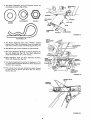
MOWER
AND
DRIVE
BELT
IN STALLATION
Your tractor has been shipped with the Mower Suspension
Bracket banded to the frame° Remove bands and lower Mower
Suspension Bracket (Fig 11)
DRIVE
BELT INSTALLATION
BRACKET
1,, Remove Hood and Grill (see page 24)°
FIGURE
2.
Place Mower Drive Belt over Clutch PuJley and under Idler
Pulley and Tension Pulley (Fig, 12), NOTE" PULL LEVER
UP TO SWING TENSION PULLEY FOR BELT CLEARANCE_ Make sure narrow "V" side of Beit is engaged with
each Pulley,
3_
Pull Mower Drive Belt over Front Mower Suspension Bracket (Fig° 13)_
11
4. Replace Hood and Grill°
CLUTCH
MOWER SUSPENSION
BRACKET
MOWER
DRIVE
BELT
LEVER
MOWER
DRIVE BELT
TENSION
PUt_,LEY
IDLER PULLEY
FIGURE 12
-8 -
FIGURE 13
4, TheMowerSuspension
ArmsandFasteners
(shownfull
sizebelow)arefoundinBagof Parts,
O
____00
CLIP
C _
RETAINING
O
BRACKET
LOCKWASHER
RETAINING
CLIP
HEX NUT
/
•
WASHER
WASHER
LIFT LINK
STUD
SUSPENSION
ARM
HEX
NUT
LOCKWASHER
FIGURE 14
RETAINING
CL|P
DEPTH
ADJUSTMENT
KNOB
5. The Mower Suspension Arms have "FRONT"
Stamped
between holes. Place the Suspension Arms on Brackets on
both sides of Frame. Retain with Retaining Clip (Fig° 14).
6. Slide Mower under Tractor.
\.
ATTACHMENT
HANDLE
Deflector to right hand side..
7. Siide Front Suspension Brackets into Mower Brackets, Retain with Release Pins (Fig= 15). Turn Depth Adjustment
Knob counterclockwise (_)
until it stops,
8, Slide Suspens}on Arms into Rear Suspension
Retain with Reiease Pins (Fig, 15),
Brackets=
REAR
SUSPENSION
BRACKETS
9. Turn Depth Adjustment Knob (Fig. 15) clockwise (/'_)
to remove slack from Mower Suspension. Raise Attachment
Handle to full up position.
10,
Press plunger
down
to lower mower to
Mandrel
(Fig. I6),
and push Attachment
ground.
Roll
D'rlve
Handle
Belt
over
MOWER
BRACKET
RELEASE PIN
PiN
forward
FRONT
SUSPENSION
BRACKET
Primary
MOWER
BELT
FIGURE
15
FIGURE
16
DRIVE
PRIMARY
MANDREL
-9_
MOWER ADJUSTMENT
Adjust the mower while tractor is parked on level ground or
driveway, Make sure tire pressures are 14 PSI in front; 10
PSI in rear.
POSITION
ATTACHMENT
HANDLE
SiDE
FIAIRPIN
CLIP
z1
1, Use a ruler to make sure Flanges at rear of mower deck
are the same height from the ground on each side (Fig
19).
J
GAUGE
WHEEL
TO SLIDE ADJUSTMENT
CLEVIS
PIN
2.
_,
If adjustment
side of tractor
is required,
above Foot
3o Move Attachment
FIGURE
snap out Access
Rest (Fig,, 18),
Cover
on LH_
Handle to full '_UPt' position (Fig_ 17).
17
4. To lower' right side of mower, loosen Nut "B" and screw
Nut "A" down on Adjustment Rod.
5o To lower left side of mower, loosen Nut "B" and screw
Nut "A I_up on Adjustment Rod.
6o Adjust until both rear• mower flanges
are theIT same
height
_]
tI
II
above the ground, T=ghten Nuts A and B securely,
Snap Access Cover in place,
NUT
"'A"
©
FRONT
TO
REAR
ADJUSTMENT
Move Attachment
Handle to full "UP" position (Fig. 17).
After leveling side to side, measure R.H. Flanges at FRONT
AND REAR OF MOWER° The Roll Front Flange should
measure 3/4" lower than the R.H Rear Flange (Fig t9)
If adjustment is required, follow procedure below
FIGURE
18
FRONT
FLANGE
REAR
FLANGE
FIGURE 19
FLANGE
- 10-
1. TO RAISE FRONT_OF MOWER
Loosen Nuts "D _, Screw Nuts "C" up onto Suspension
Arms (Fig. 20). NOTE; SCREW NUTS "C" ON BOTH
SUSPENSION ARMS THE SAME NUMBER OF TURNS
SO MOWER WILL REMAIN LEVEL. Tighten Nuts "D"
securely.
2. TO LOWER FRONT OF MOWER
Loosen Nuts "C'L Screw Nuts "D" down Suspension Arms,
NOTE: SCREW NUTS "D" THE SAME NUMBER OF
TURNS SO MOWER WILL REMAIN
LEVEL. Tighten
Nuts "C" securely.
3, With mower deck at desired height, set Gauge Wheels (Fig°
! 7} to lowest position without touching the ground_
Use Adjustment
Handle to set mower at the approximate
cutting height you need. Use Clevis Pins (Fig. 17) to set gauge
wheels at lowest point without touching the ground.
NUT "D"
SUSPENSION
ARMS
FIGURE 20
MOWER
OPERATUON
When ready to mow, lower Attachment
Handle (Fig. 21)
to preferred mower height. Select a gear that a)lows mowing
at full throttle. This allows the mower blades to lift and cut
the grassefficiently.
MOWER
ATTACHMENT
HANDLE
/
ENGAGEMENT
Pull Clutch Switch (Fig. 22) out and up to engage clutch.
There will be an engine hesitation as the clutch engages.
DEPTH ADJUSTMENT
Fine adjustment of mower height is controlled by the Depth
Adjustment Knob. Turn clockwise (_)
to raise mower° Turn
counterclockwise 0_'_) to lower mower (Fig, 22).
FIGURE 21
CLUTCHSW|TCH
"ON"POSITION
CLUTCH
SWITCH
"OFF"
POSITION
DEPTH
ADJUSTMENT
KNOB
,FIGURE 22
-11 -
Use the Runner on the right hand side as a guide; the blade
cuts approximately an inch outside the runner,,
!
f
NEVER
REMOVE
DEFLECTOR.
KEEP
HANDS AND FEET FROM UNDER MOWER,
-,_-,-RoH,RUNNER
DEFLECTOR
.
FIGURE 23
Before leaving operator s position:
a, Shift transmission to neutral,
b, Set parking brake°
c. Disengage attachment clutch.
do Shut off engine.
eo Remove ignition key,
3. Wait for all movement
to stop before servicing machine.
4. Keep people and pets a safe distance away from
machine.
MOWER
EXCEPT WHEN SITTING
ON
NEVER ENGAGE ("ENGAGE" POSITION)
TRACTOR SEAT.
TIRE CHAINS CANNOT
HOUSING ATTACHED=
FIGURE 24
DEPTH
ADJUSTMENT
KNOB
BE USED WITH
THE
MOWER
READ THE "RULES FOR SAFE OPERA,
TION"
CAREFULLY
BEFORE OPERATING YOUR MOWER° REFER TO PAGE 3.
5_
PLUNGER
ENT
HANDLE
6.
FIGURE 25'
-12-
Use Attachment Handle to lower mower into cutting position, Start mowing at stow speed and increase ground speed
by increasing throttle as conditions will permit,_ Average
cutting height is approximately
2 - I/2 to 2 - 3/4 inches,
Height of cut can be adjusted by means of the Depth
Adjustment Knob (Fig, 25). Turn Depth Adjustment Knob
(clockwise ((_}
or counterclockwise
(f_,)
to match preselected Lift Control Lever mowing height.
Drive so that clippings are discharged onto the area that has
been cut. Have the cut area to the right of the machine°
This will result in a more even distribution
of clippings
and more uniform cutting. When mowing large areas (Fig.
24), start by turning to the ;ight so that the clippings will
be discharged away from shrubs, fences, driveways, etc.
After two or three rounds, mow in the opposite direction
making left hand turns until f_nished. If grass is extremely
tall, it should be mowed twice. The first time cut relatively
high_ The second time to the desired helght, The left hand
side of mower should be used for trimming.
MOWER
MAINTENANCE
INSTRUCT,ONS
MOWER CLUTCH
":'OFF" POSITION
BEFORE MAKING
ANY INSPECTION,
ADJUSTMENT OR REPAIR: PUSH TRACTOR
CLUTCH-BRAKE
PEDAL
COMPLETELY INTO BRAKE POSITION MOVE
SHIFT CONTROL LEVER TO NEUTRAL
POSITION. PLACE PARKING BRAKE IN
"ENGAGED"
POSITION.
TURN
OFF
MOWER CLUTCH SWITCH IFIG. 26).
IGNITION
SHUT OFF THE ENGINE. MAKE ABSOLUTELY SURE THE BLADES AND ALl.
MOVING
PARTS HAVE COMPLE'TELY
STOPPED. REMOVE THE IGNITION KEY.
DISCONNECT THE SPARK PLUG WIRES
FROM THE SPARK PLUGS AND KEEP
WIRES AWAY FROM THE PLUGS TO
PREVENT INJURY FROM ACCIDENTAL
STARTING,
BLADE
PARKING
:BRAKE
CLUTCHBRAKE
PEDAL
"BRAKE"
POSITION
FIGURE 26
CARE
For best results mower blades must be kept sharp, The blades
can be sharpened with a few strokes of a file or on a grinding
wheel We suggest they be sharpened after every 15 hours of
mowing° Do not attempt to sharpen while on mower.
1. When grinding, care should be taken to maintain blade balance and the blade should be checked for proper balance
before reinstallation on mower_ Unbalanced or bent blade
will cause excessive vibration when running and eventual
damage to mower or engine° Replace bent or damaged
blades_
2. To ensure satisfactory operation, it is recommended that
before the start of each mowing season, the oldblades be
discarded and replaced with new blades. Mower blades can
be purchased at any Sears Service Center/Departments and
most Sears Retail Stores=
BLADE
SWITCH
,
LOCKWASHER...----_._
BLADE
HEX HEAD HEAT--'-_
TREATED
GRADE5
BOLT
_:_
FIGURE 27
REPLACEMENT
It is not necessary to remove mower
placement.
By moving
Lift Control
tion wilt permit access to blades
from tractor for blade re=
Lever to up (Rear) posi-
A GRADE 5 HEAT TREATED BOLT
CAN BE IDENTIFIED
BY THREE
LINES INDICATED
ON THE BOLT
HEAD AS SHOWN AT LEFT.
1.. Remove the Hex Head Bott_ Lockwasber and Fiat Washer
(Fig. 27L
2,, Install new blade with SHARP EDGE DOWN and secure
with Flat Washer, Lockwasher and Hex Head Bolt TIGHTEN SECURELY,
ALWAYS USE GRADE 5 HEAT TREATED
BOLTS TO ATTACH
BLADES, CHECK
BOLTS IN BLADES OCCASIONALLY TO
MAKE SURE BOLTS ARE TIGHT° TORQUE BOLTS 30- 35 FT. LBS.
DA, LY IWA, NTENANCE
Make sure ati nuts on bolts are tight, cotter p_ns and retainer
springs are secure. Keep blades sharp. Observe all safety pre,
cautions. Keep mower well lubricated°
-13-,
CLEAN|NG
I
I
A
_
I
MOWER
DISCONNECT
SPARK
PLUGWIRES
TO1
PREVENT
ACCIDENTAL
STARTING
FORE
CLEANING.
BE- |
1
Water pressure from a garden hose wil! remove fresh clippings
from underside of mower_ Clean mower after each mowing,
/
LUBRtlCATII
ON
Under normal usage the Mandrels should require lubrication
after every 50 hours of operation and at the end of each season. The outer Mandrels should be filled with grease (six shots)
thru the Grease Fittings located between Mower Blade and
underside of the Mower Housing (Fig° 28)° Wipe fitting clean
before greasing, Use high performance, extreme pressure
lubricating grease. Amdex No, I EP or equlvalent. This grease
may be obtained by ordering thru your nearest Sears Repair
Parts Department, Part No, 2557R or equivalent°
FIGURE 28
POWER
TA/KE=
OFF
CLUTCH
The Power Take-Off Clutch (Fig, 29) should provide years of
service. The Clutch incorporates a built in brake that stops the
Pulley almost immediately° Eventually, the internal brake will
wear so the mower blades wilt not stop as recommended. Adjustment should be made by a Sears Service Technician_
POWER
"-OFF
CLUTCH
FIGURE 29
_14_
OUTER
BLADES
(CENTER
BELT
TO OUTER
ROUTING
1o Remove
DRIVE
DECAL
Mower
from
MANDRELS)
UNDER
MOWER
Tractor(see
below)°
2, Remove Top Cover Self Tapping
Idler Arm Bolt,.
3,
BELT
Ro!l Belt over the top of the R.H.
DECK
COVER,
ilDLER
tNUT
ARM
CENTRAL
MANDREL
SHEAVE
LH. M LANDREFLAT IDLER
SHEAVE
SHEAvER'H"
MANDREL
Screws, and Nut from
Mandrel°
4. Pult Belt off all other Mandrels,
5° Remove
any dirt and grass which
around Mandrels and Idler Arm,
may
have
accumulated
6. Check Deck idler Arm Assembly and Flat Idler to see that
they rotate freely (Fig, 30)_
7, Be sure spring is hooked in Deck Idler Atm Assembly and
on bolt in Mower Housing (Fig, 30),
FIGURE 30
8. Install new Belt in groove of L,H, Mandrel Sheave, lower
groove of Center Mandrel Sheave and around Flat Idler as
shown (Fig, 30)_
9, From a position at discharge end of mower, roll Belt into
groove of RH, Mandrel Sheave (Fig 30),
/
10o Rotate Center Mandrel
is in grooves properly.
Sheave by hand
MANDRELSHEAVEo
BLADES WILL ROTATE
ATTACHMENT
HANDLE _
to make sure Belt
WITH CENTER
"BELT_
11, Reassemble Top Cover to Deck, Tighten
ly,
12.
Install Mower
to tractor
all Screws secure-
ISUSPENSION
BRACKETS
,g I I
RELEASEPIN
(see page 8)
BRACKETS
RELEASE
\
REMOVING
FROM
I.,Lower
2
TRACTOR
Mower
Pull the four
(Fig, 31 ),
3_ Pull back
4, Slide
drel.
MOWER
FIGURE 31
(4}
on Attachment
Mower
forward
5,, Raise Attachment
tractor.
Release
Lift
Pins out
Lift
Handle
and remove
Handle.
of Suspension
and tock
Belt
from
Sl_ide Mower
into
Brackets
place.
Primary
Man-
out from
unde_
NOTE: WHEN OPERATING TRACTOR WITHOUT MOWERi
REMOVE IDLER BRACKET FROM FRONT OF TRACTOR.
1, Pull Belt up through Idler Bracket and out of tractor, Use
Lever to swing Tension Pulley for Belt removal.
2, Remove Lockwashers and Nuts from Idler Bracket (Figi
32).
STORAGE
IDLER
BRACKET
Remove mower from tractor for winter storage. When mower
is to be stored for a period of time, clean it thoroughly, remove all dirt, grease, leaves, etc, Give blades and underside of
housing a good coat of grease or rust preventative, Store in a
clean dry area,
HER
NUT
LEVER
Each outer mandrel should be greased thru the Grease Fitting
located between mower blade and underside of the mower
housing (Fig, 28), Give each Grease Fitting 6 shots of Grease.
Wipe fitting clean before greasing. Use high performance extreme pressure lubricating grease. {Amdex No. 1 EP or' equiva_
" lent), Wipe mandrel dean of excess grease. This grease may be
obtained by ordering thru your nearest Sears Repair Parts Department. Part No. 2557R
NUT
LOCKWASHER
FIGURE 32
ATTACHMENT
SPRING
BUSHING
LOFT
ADJUSTMENT
Due to different
weights of Attachments_ the Attachment
Lift Spring may require adjustment. _he Adjustment
Bolt
is located on rear of tractor top left side (Fig. 33).
ENT
LIFT SPRING
1,_ Holding
Spring
Bushing
with
Wrench,
loosen
Jam
Nut,
2. Turn Adjustment Bott clockwise (F'_)
to extend Spring
and reduce lift effort (for heavier Attachments),
3, Turn Adjustment Bolt counterctockwise ((_,)
Attachments),
(for lighter
JAM NUT
4, Retighten
Jam Nut against Spring
Bushing,
NOTE: DO NOT ADJUST FOR MAXIMUM
SPRING TENSION WHEN USING LIGHT ATTACHMENTS
SUCH AS A
MOWER. ADJUST
LIFT SPRING TO AID IN LIFTING
ATTACHMENT
, DON'T OVER POWER SPRING. WHEN
REMOVING
ATTACHMENT
ALWAYS
ADJUST
WITH
SPRING TENSION TO ITS LOWEST POSITION.
FIGURE 33
DISCHARGING
CHARGING
\
/
\
TRACTOR
MA|NTENANCE
INSTRUCTIONS
/
/
D C AMPERES
IC3
a
=
r_
=
=
1:3
15
lo
5
0
5
to
t5
To keep your tractor running better', longer; perform necessary service using the following
Maintenance Schedule.
Each time you start your tractor, check your Ammeter (Fig,
34), The needle should move towards the + (charging) mark
indicating the battery is being charged as you operate the tractor,. The headlights wlll not show a discharge on the ammeter
because they are not connected to the battery (they have their
own electrical source, see page 26). If you have a lift motor
connected it wilt show a discharge when being operated,
AMMETER
DISCONNECT
SPARK PLUG WIRES TO
PREVENT ACCIDENTAL
STARTING BEFORE MAKING ANY INSPECTION, ADJUSTMENT OR REPAIR (EXCEPT CARBURETOR).
FIGURE 34
-16-
1, CHANGE ENGINE OIL
Changing Oil after the first two hours will help eliminate
break*in residue which might be damaging to your Engine.
NOTE: BE CAREFUL NOT TO ALLOW DIRT TO ENTER
THE ENGINE WHEN CHANGING OIL.
ao Drain oil with Engine warm. Remove Hood and Grill
(see page 24). Place Hose on Oil Drain and loosen Oi!
Drain Wing Nut° Catch oil in a suitable container.
Tighten Oil Drain Wing Nut after all oil has been drained
from Engine° Remove Hose from Oil Drain,
b. Refill Engine Oil. (See chart, page 6). Refill capacity
is 3 pints. NOTE: DO NOT OVERFILL,
Replace Dipstick.
EVERY
ENGINE
OIL
DIPSTICK
AND
FILL
TUBE
__
HOURS
1, CHECK ENGINE OIL LEVEL
DO NOT CHECK ENGINE
WITH ENGINE RUNNING°
OIL
LEVEL
FIGURE 35
Several minutes after stopping Engine, check Engine Oil
Level with Tractor on level ,ground,, Wipe dipstick (Fig.
35) clean push it down tight for a few seconds, remove and
read Od Level,, If necessary, add Od until FULL mark =s
reached. (See chart, page 6)_ NOTE: DO NOT OVERFILL
•
.
,
II
11
,
- 17-
(EVERY 15 HOURS IF OPERATING
IN VERY DUSTY CONDITIONS)
1.i CLEAN AIR FILTER
a. Unscrew Knob (Fig, 36) to remove Cover.
b. Remove Nut and Washer _o remove Cartridge Plate,
Paper Cartridge and Oil Foam Pre-Cleaner.
c. Wash Foam Pre-Cleaner in detergent and water,,
d, Rinse. squeeze (rather than twist) and allow to dry
thoroughly _ "
e. Coat with three Tablespoons of SAE. 30 Engine Oil,
squeeze to distribute evenly, and squeeze out excess°
f. Check Paper Cartridge. Replace if excessively dirtyr,
g. Reassemble Paper Cartridge and re-positlon on Tractor.
NOTE: NEVER RUN ENGINEWlTHAIR
CLEANER REMOVED
AS DIRT
(DUST} WILL
DAMAGE
THE
ENGINE_
_WASHER
CARTRIDGE
PLATE
PAPER
CARTRIDGE
OIL FOAM
PRE-CLEANER
2_
BODY
3_
CLEAN AIR SCREEN
Air' Screen (Fig, 38) must allow free-flow of air to prevent
Engine damage from oven-heating. Clean with a wire brush,
or compressed air to remove dirt, chaff, stubborn dried
gum and fibers°
CHANGE
The
FIGURE 36
5_
FRONT
AXLE
PIVOT
FRONT SPINDLE
(GREASE
FITTING)
LEFT 8= RIGHT)
LUBRICATE THE
STEERING PLATE
IN AREA OF
SECTOR GEAR
Engine
Oil
FRONT
ENGINE
_=_
_ _I,L_')
....
PIVOT
_=_L
.
_"
18-
are suspended
POINTS
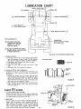
b_ Hood Hinges.
c, Foot Pedal Shaft (both ends).
d_ Lift Shaft (both ends).
e, Steering Plate.
SEE LUBRICATION
CHART,
PAGE
(GREASE
FITTING}
LEFT & RIGHT)
materials
LUBRICATE STEERING AND FRONT WHEELS
There are four Grease Fittings on your Tractor (Fig. 37).
Using a Grease Gun. give each Grease Fitting two shots of
Extreme Pressure Lubricating Grease Amdex No. I or
equivalent (available through your Sears Service Center).
Sears Part No,. 2557R.
Place several drops of S.A.E. 30 Oil
move against each other, especially:
a. Front Axle Pivot,
WHEEL
is at the end of a day's
CLEAN FRONT GRILL
The front Grill (Fig, 2) must allow free flow of air to prevent engine damage from overheating,
a, Brush off debris.
6_ OIL
FIGURE 37
FIGURE 38 _
OIL
to drain
operation
when all dirt and foreign
in the hot Oil. Refer to page 17.
4_
OIL FILL _
DIPSTIC v'
ENGINE
best time
at points
19_
where
parts
LUBRICATION
(_
C'2_ WHEEL
SPINDLE
/'SPINDLE
(_
BEARINGS-_
_WHEEL
ENGINE
BEARINGS
@
(_)
BOTH ENDS OF
FOOT PEDAL SHAFI'
--
O
BOTH ENDS LIFT SHAFT (_)
SAE MOTOR OIL
--
EXTREME PRESSURE
LUBRICATING GREASE
AMDEX NO, t, SEARS
PART NO. 2557R
Q
TRANSAXLE
(CHECK LEVEL AT REAR
FILL PLUG) !(_
REFER TO ENGINE OIL SPEC'S.
(UNDER INITIAL PREPARATION
IN OWNERS MANUAL)
SEE PAGE 14 FOR MOWER LUBRICATION.
7. CHECK
a,
BATTERY
Electrolyte
solution
levei in each Battery
Cell should be
even with
bottoms
of tubes in ceils (Fig, 39)o Add distilled
water if necessary,, NOTE:
DO NOT OVERFILL°
b, Keep Battery and Terminals
clean. Refer to step 8,
c. Keep Battery Bolts tight,,
d. Keep Vent
Caps tight
and small vent holes in Caps
open.
e_ Recharge SLOWLY
at 3 amperes if necessary.
8o CLEAN BATTERY AND TERMINALS
Corrosion and dirt on the Battery and Terminals cause
the Battery to "leak" power and hinders the operation of
the charger.
a. Remove the Battery from the Tractor and wash with
four tablespoons of baking soda to one gallon of water,
NOTE: BE CAREFUL
NOT TO GET THE SODA
SOLUTION INTO THE CELLS. Rinse the Battery with
pfain water, dry and reinstall on Tractor.
b. Clean terminals and cable ends with a wire brush until
bright. Replace Battery Cables. Coat terminal connections with Vasoline.
w.v
CUT-AWAY
VIEW
VENT CAP
}ATTERY
. TUBE
FIGURE 39
.,,_._HEAT SHIE LD
.ou.s
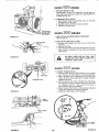
1. CLEAN ENGINE COOLING FINS
Remove any dust, dirt or oil from Engine Cooling Fins
to prevent Engine damage from overheating (Fig. 41).
Air Guide Covers must be removed (Fig, 40)_
2. MUFFLER
Do not operate the tractor without a Muffler (Fig. 40) or
tamper with the exhaust system° Damaged Mufflers or
spark arresters could create a fire hazard. Inspect periodically and repJace if necessary° If your engine is equipped
with a spark arrester screen assembly, remove every 50
hours for cleaning and inspection. R_plaee if damaged.
- 19 -
AIR
SCREEN
FIGURE 40
svs.vI]®®.o..s
1. REPLACE SPARK PLUGS
Replace Spark Plugs at the beginning of each season or
every 100 hours_ whichever comas first. Gap should be set
at .030 inch (Fig. 42).
2_ LUBRICATE BALL JOINTS
a Move Rubber Boots to expose Ball Joints on Tie Rods
and Steering Link (Fig. 43)_
b. Coat Ball Joints with Silicone Spray Lubricant
c. Reposition Rubber Boots_
Ew.v
CLEAN
AREA
OF ALL DIRT
AND DEBRIS
FIGURE
.o..s
1_ REPLACE AIR CLEANER
Refer to page 18,
41
PAPER CARTRIDGE
2. REPLACE IN*LINE FUEL FILTER
a, Remove Hose Clamps from Fuel Lines at Fuel Filter
(Fig_ 44),
b. Remove Fuel Filter°
co Place new Fuel Filter in position with fuel line (arrow on
side of Filter in direction of Fuel Filter) and reinstall
Hose Clamps.
GAUGE
PLUG
BE SURE THERE ARE NO FUEL LINE
LEAKS AND THAT HOSE CLAMPS ARE
PROPERLY INSTALLED.
FIGURE 42
TIE
ROD
1o CHANGE TRANSAXLE OIL
ao Block up Rear Axle (Fig. 45) securely or use a Tractor'
Jack. Remove left Rear Wheel by removing Hub Bolts.
b. Drain Transaxle Oil by removing Drain and Filler Plugs
(Fig's. 45 & 47) and catching Oi! in suitable container..
Replace Drain Plug.
c, Refill Transaxle with S=A..E 30 (SC, SD or SE) Motor
Oi!o Capacity is 5 quarts. Pressure Relief Valve (R..H side
of Transaxle) (Fig. 45 - Inset) may be held open to
allow Transaxie to fill more quickly.
do Check Pressure Relief Valve° It should spring completely
closed when pulled out by hand and released.
eo Reposition wheel. Secure with Hub Bolts.
BALL JOINTS
TIE ROD
JAM
STEERING
NUTS
LINK
BOOT
FIGURE 43
HOSE
CLAMPS
FUEL
FILTER
LH. SIDE
PLUG
FIGURE 44
- 20-
FIGURE 45
AS NEEDED
\
.\
1, Make sure all nuts on bolts are tight and cotter pins are secure° Observe
all safety
precautions,
Keep Tractor
well
lubricated
(refer to page 18),,
2o TOE-IN
TIE ROD
TIE ROD
._..._
ADJUSTMENT t \ \
SLEEVE8
_ \\
ADJUSTMENT
If any parts in Front Axle or Steering Mechanism
are being
replaced, Toe-In adjustment
is required.
a, Loosen
.Jam Nuts (Fig_ 46) at each end of Tie Rod
Adjustment
Steeves,
b, Adjust
both Tie Rods so that Tie Rod Joints measure
Ii
9- 5/8
from center to center,
c, On front of front tires measure distance from center to
center (measurement
No,1}o
d, On rear of front
tires measure distance from center to
center (measurement
No, 2),
eo Compare measurements
- measurement
No. 1 should be
1/8- 1/4 less than measurement
No. 2,
f, If not adjust each Tie Rod equally to get correct
measuremento
_BALL
fJ
JOINTB_
T,E.oo
(%
"_RUBBER
BOOT
STEERING
LINK
"_
J
FIGURE 46
g, Tighten
Jam
Nuts
making
sure Tie
Rod Joints
are
parallel (180 °) to each other. This adjustment
secures
proper front wheel Toe-In and Steering operat_ono
•)
TRANSAXLE
.tUG
3. CHECK TRANSAXLE
OIL LEVEL
a, Remove Filler Plug (Fig, 47) from Transaxieo Oil Level
should be even with Filler Piug threads° Add SoAoE_30
Motor Oii if necessary.
b Check Pressure Relief Valve (Fig, 45 - inset) located on
R.H side near top, It should spring completely closed
when pui{ed out by hand and released.
4. BRAKE ADJUSTMENT
IF TRACTOR
REQUIRES MORE THAN
SIX
FEET
STOPPING
DISTANCE
IN
HIGHEST
GEAR ON A LEVEL
DRY
CONCRETE OR PAVED SURFACE THEN
BRAKE MUST BE ADJUSTED,
a.
Remove
(4) Hex Washer Head Tapping
Screws from
Shift
Cover Plate (Fig, 48), located on top of tractor
frame° Remove the Cover Ptateo
b.
Loosen Jam Nut (G) on Brake Rod (B) at Clevis (C)
(Fig. 49). If you find it difficult
to loosen Jam Nut (G),
remove Cover Plate in LH, Frame Rail,
c,
Rotate
Brake Rod (B) counterclockwise,
((-_)
Brake Rod out of Clevis (C) four to six turns,
Start tractor
with Transmission
in "NEUTRAL"
tion
d,
FIGURE
47
turning
posi-
"5 ...........
e, Depress
Brake-Clutch
Pedal to the point where
Belt
stops moving
Hold Brake-Clutch
Pedal in position
by
engaging Parking Brake
If Belt begins to move after engaging Parking Brake, depress Brake-Clutch
Pedal to next
notch on Parking Brake.
f, Shut engine off. Rotate
Brake Rod (B) clockwise
by
hand, turning
Brake Rod into Clevis (C), until tight,,
T_ghten Jam Nut (G) on Brake Rod (B) at Clevis (C)
(Fig, 49)°
g, Reinstall
Lift Cover Plate and four (4) Mounting
Screws,
If Cover Plate was removed
in step b it should be re-
E
F
placed
C
- 21 -
iFIGURE
49
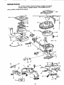
5o CARBURETOR ADJUSTMENT
Never attempt to change maximum engine speed. This is
preset at the factory and should only be changed by a qualified service technician who has the necessary equipment.
a. Move Throttle Control (on the dashboard) to I_SLOW'*
position. Remove'All: Cleaner (Fig. 36).
b. Check that two holes "A" line up. If not, loosen Clamp
Screw and adjust Throttle Cable until the two holes do
line up (Fig. 50 - Inset),
_HROTTLE
r
i _CABLE
GOVERNOR
CONTROL
REFER TO "STARTING
PAG E 6.
THE
ENGINE",
co Start Engine and allow to warm for five minutes. Make
final adjustments with engine running.
d_ High Speed is fixed, no adjustment is possible,,
e, Adjust Carburetor Mixture Screw to suggested initial
setting,
-- Turn Mixture Screw clockwise (/_)
closing finger
tight ONLY, and then turn counterclockwise
(f'_)
1 - t/2 turns (Fig. 51).. CAUTION:
VALVE MAY
BE DAMAGED IF TURNED IN TOO FAR.
f. Hold Governor Control against Throttle
Stop. Turn
Mixture Screw clockwise (('_)
until engine begins to
run rough (Fig. 51).
g. Turn Mixture Screw counterclockwise (_)
until engine
begins to run rough,. Set Mixture at smoothest idle
between the two points attained in steps f and go
h. Release Governor Control. Engine will speed up for
governed idle. Replace Air Cteanero
J
HOLE"A"
FIGURE 50
6o V-BELT ADJUSTMENT
A new V-Bett may stretch after the first few hours of operation resulting in loss of ground speed_
a. To tighten Belt, remove (4) Hex Washer Head Tapping
Screws from Shift Cover Plate (Fig. 48) located on top
of tractor frame• Remove the Cover Plate.
•
, ,
b. Place Parking
Brake Lever _in It ENGAG E D li pos=tlon,,
!1
Refer to Stopping
Your
Tractor
page
7,,
t*lr.
li"
,
.
c. Loosen Nut
A located on outside of R.H. Chassis
Frame (Fig. 56), slide Take-Up Idler down approximately 1/2" and tighten Nut "A",
d. Disengage Parking Brake.
e,, Check position of Clutch Idler Bracket (Fig. 52).
f+ Repeat steps b thru e untd a 1 - 1/t6
dmenson is
obtained between Idler Tab and Frame as shown in Fig
FIGURE 51
52.
g. Tighten Nut "A" securely.
h, Reinstall Shift Cover Plate and (4) Screws removed in
step a,
R.H. SIDE OF TRACTOR
ENGINE
PULLEY
IDLER
BRACKET
1-1/16" i
/.
_?_
|
....
t
NUT "A"
CLUTCH
I
TAKE. UP
IDLER "
,FIGURE 5:2
- 22-
7, V-BELT
REPLACEMENT
BELT
REMOVAL
The belt on this tractor
is special for this application.
Always
replace with the Sears belt number
in the parts
list. It is not necessary to remove mower°
a, Raise hood
and disconnect
negative
ground
battery
cable.
b° Set parking brake (to get belt stack),
c_ Loosen (do not remove)
two Engine Pulley Belt Guide
Bolts and swivel
R,H. side of Belt Guide up, Tighten
LHo Bolt to hold Belt Guide in position
(Fig° 53).
do Roll Belt off Enqine Pulley,
e, Roll
Belt off I_V"
Idler,
Flat Idler
and Adjustable
f.
g,
FIGURE 54
THERE
IS A BELT
INSTALLATION
LEFT HAND FOOTREST
DECAL
a,
Push Belt down
from
Engine
Pulley area_ Place back
(flat)
side of Belt on Flat tdler_ (Flat
Idler is next to
Frame.)
b. Place Belt on Adjustable
Idler and over Clutch Pulley
"V"
(narrow)
part of Belt should engage Clutch Pulley,
co Place Belt around
Transaxle
Pulley.
"V"
part of Belt
g
TRANSAXLE
PULLEY
INSTALLATION
NOTE:
UNDER
e,
f
PULLEY
Idler Pulleys (Fig. 54)°
Pull Belt off Clutch Pulley - between
Pulley and Frame
Pull Belt off Transaxle
Pulley.
Loosen Nut "A" on R.H. outside of Frame (Fig. 56)°
BELT
d
ADJUSTABLE
IDLER
"V"IDLER
should engage Transaxle
Pulley,
Make sure 1_, V It part of Belt engages
Idler
!tvll
(Fig
O
O
1
3
54).
-I
Roll Belt over Engine Pulley,
Loosen L.H
Engine Pulley Belt Guide Bolt and swivel
Belt Guide onto R_H. Bolt. Tighten
LH° and R_H_ Botts
securely (Fig. 55).
Release Parking
Brake. NOTE:
WHEN
A NEW BELT
HAS BEEN INSTALLED,
YOU MUST CHECK V-BELT
ADJUSTMENT
AND BRAKE
ADJUSTMENT
8_ TIRE CARE
a, Maintain
tire
at 10 PSL
I
FIGURE 55
pressure
in front
at
14 PSI and rear tires
b
Keep tires free of gasoline, oil, or insect control
chemicals which can destroy rubber°
c Avoid stumps, stones, deep ruts and other hazards that
may cause tire damage.
d_ Removing front wheel for tire repair (Fig 57).
--- Block up front axle securely°
e,
--
Remove
Hub
wheel removal
Cap,
Klip
Ring
-
Repair tire and reassemble° Replace Washer and snap
Klip Ring securely in axle groove
Replace Hub Cap.
Removing rear wheel for tire repair.
o-- Block up rear axle securely
--- Remove
Hub Cap and (5) Hub
removal.
-_- Repair tire and reassemble.
Bolts and Hub Cap securely.
WHEN
and
Bolts
Replace
MOUNTING
BEADS ARE SEATED,
CAN CAUSE A FATAL
Washer
to allow
to allow
and tighten
TIRES,
\
wheel
Hub
UNLESS
OVERINFLATION
EXPLOSION.
\
/
/
FIGURE 56
/
1
BELT
WASHER
FIUB
CAP
LOOSEN
KLIP RING
FIGURE 53
PULLEY
- 23 -
FIGURE
57
9,
WiRE
CONNECTION
FINISH
Keep tractor finish and seat free of gasoline, oil, insect
chemicals or battery electrolyte. Protect painted surfaces
with automotive type wax,
10, HOOD REMOVAL
a_ Lift Hood_ Disconnect Headlight Wiring Connection
(Fig. 58},
bo Unscrew one Screw at rear of each Side Panel {Fi0.
58)°
co Pivot Hood and Side Panel forward and lift off tractor
(Fig. 59).
d. To replace, reverse the above procedure.
SCR
FIGURE 58
FIGURE 59
DATES
i AS YOU COMPLETE
Check Engine Oil Level
,,_m__/_
¢_._-_
_;k___ _
___ ____q."_>___'J, 9,'_,
_i_
(_hange Engine Oil (see chart, page 6)
Lubricate Pivot Points (see page 19)
Check Brake Operation
Clean Air Screen
Clean Air Filter
Replace Air Cleaner Paper Cartridge
Clean Engine Cooling Fins
V"
Replace Spark Plug
Check Battery Level
Check Tire Pressure
Replace Fuel Filter
- 24 -
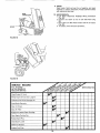
TROUBLE
SHOOTING
POSSIBLE CAUSE
POSSIBLE REMEDY
WILL NOT START
Clutch-Brake Pedal in drive position
Attachment Clutch Switch in "ENGAGED" position
No gasoline in Fuel Tank or clogged Fuel Line or Fuel
Filter
Blown Fuse
Dead Battery
Defective Ignition or loose Wiring
Spark Plug fouled
Push Pedal into brake position (Fig, 8).
Move Lever to "DISENGAGED"
position (Fig, 9)
Fill Tank with fresh Gasoline, Check Fuel Line (Fig, 44)
and Carburetor (clean if necessary)
Check for fault and replace Fuse
Recharge or replace Battery
Check Wiring
Replace Spark Plug and adjust gap (Fig. 42)
HARD TO START
Choked improperly, flooded
Place
Engine
Throttle
Control
in fast
position
(Fig,
9) and
Clogged Fuel Tank, Fuel Line or Fuel Filter
Spark Plug fouled
Defective
Battery
Defective
Ignition or loose wiring
Water in gasoline or old fuel
starter several times to clean out gas
Remove and clean (Fig, 44)
Replace Spark Plug and adjust gap (Fig, 42)
Recharge or replace
Check the wiring and Spark Plug
Drain Fuel Tank and Carburetor,
use fresh fuel and
replace Spark Plug
Improper
Carburetor
Poor compression
Make necessary adjustments
Major engine overhaul
adjustment
(Fig
50)
ENGINE MISSES OR LACKS POWER
Engine overloaded
Ctogged Fuel Filter
Clogged Fuel Tank
Partially plugged Air Cleaner
Improper Carburetor adjustment
Dirty Air Screen
Low oil level
Spark Plug fouled, improper gap or wrong type
Faulty ignition
Poor compression
Gasoline in oil
Dirty Air Cleaner
Shift to a lower gear or reduce load
Remove and replace (Fig, 44)
Remove and clean
Remove and clean (Fig, 36)
Make necessary adjustments (Fig, 50)
Clean Air Screen, Cylinder Fins (Fig, 41) and Muffler
Add or change oil (Fig. 35)
Replace Spark Plugs and adjust gap !Fig 42)
Check Spark Plugs and for any loose wires
Major Engine overhaul
Drain Engine oil and refill
Remove and clean (Fig, 36)
ENGINE OVERHEATS
D_rty Air Screen
Low oll level
Dirty Engine
Partially plugged Muffler
Improper Carburetor adjustment
Clean Air Screen (Fig 40)
Add or change oil (Fig, 35)
Clean Cylinder
Fins, rotating Screen and Muffler
Remove and clean Muffler (Fig 40)
Adjust Carburetor {Fig, 50)
NO LIGHTS
No Headlight with Light Switch in "ON" position
and engine running
Check W_re Connections
WON'T CHARG E
Blown Fuse
Defective Battery
STORAGE
chart,
page
and Switch.
area
area
Replace Light Bulbs
Check for fault and replace
Replace
=
1, FUEL SYSTEM
NOTE: THE USE OF A FUEL ADDITIVE,
SUCH AS STABIL, OR AN EQUIVALENT,
WILL MINIMIZE THE FORMATION OF FUEL GUM DEPOSITS DURING STORAGE.
SUCH AN ADDITIVE
MAY BE ADDED TO THE GASOLINE IN THE FUEL TANK OF THE ENGINE, OR TO
THE GASOLINE IN A STORAGE CONTAINER,
If Sta_Bi! is not used all fuel should be removed from fuel
tank.,
a, Drain fuel tank and carburetor by allowing the engine to
run out of gasoline, I_IOTE: GASOLINE
LEFT IN
YOUR ENGINE WILL LEAVE GUM DEPOSITS CLOGGING FUEL SYSTEM.
b, Dispose of gasoline if not to be used. NOTE: GASOLINE STORED
FOR SEVERAL
MONTHS
LOSES
ITS VOLATILITY
(ABILITY
TO BURN EFFECTIVELY)°
2. ENGINE OIL
Drain (with engine warm) and replace with ctean engine oil.
(See
run
b Pour one ounce of oil through spark plug holes into cylinders.
c, Turn Ignition
Key to "START"
position for a few
seconds to distribute oil
d,, Replace with new Spark Plugs=
4. BATTERY
al Remove battery if tractor is not used regularly during
winter months, Store in cool, dry place {above 50°F.).
CAUTION:
A DIRTY
BATTERY
CAN
RUIN A
FLOOR.
CLEAN
BATTERY
BEFORE
STORAGE.
b. Re-charge each month if necessary. NOTE: BATTERIES
NOT IN USE FOR SEVERAL
MONTHS AND NOT
KEPT FULLY
CHARGED,
PRODUCE SULPHATE
DEPOSITS ON PLATES WHICH CANNOT
BE REMOVED BY RECHARGING.
5. GENERAL CLEANING
Clean engine, battery, seat, finish, etc. of all foreign matter,
6, STORE IN A CLEAN AND DRY AREA.
6),
3. CYLINDERS
a. Remove Spark Plugs°
Sears, Roebuck and Co. reserves the right to make any changes
in design or improvements
without
imposing any obligation
25-t°
install
the
same upon
its
items
heretofore
manufaetured_
GT 18 TWIN GARDEN
TRACTOR-MODEL
SCHEMATIC,
,
NUMBER
i;vj,
-
REDt
917,255910
BLACK
RED
POWER
TAKE.OFF
!
WHITE
INTER'K,
SW.
SOLENOID
RED_
S
WHITE
BED
ELECTRIC
BLACK
CLUTCH
AMMETER*
M
FUSE
BLACK
IGNITION
SWITCH
RED
MAGNETRON
IGNITION
30 AMP
G
PLUGS
BLACK
IGNITION SWITCH
STD365402
POSITION
CIRCUIT
OFF
M-G
ON
E3-L
START
B-S
RED
ENGINE COIL
DIODE
ASSEMBLY
)
*INDUCTIVE
TYPE. WIRE COILED AS SEEN FROM BACK OF
DASHBOARD_
5 AMPS., 10 VAC (MIN.)
@ MAX. R.P.M.
ORANGE
LIGHT
SWITCH
PTO SWITCH 4021J
LIGHTS
WILL
AMMETER°
NOT
REGISTER
ON
YOUR TRACTOR IS EQUIPPED WITH A
SPECIAL ALTERNATOR
SYSTEM. THE
LIGHTS ARE NOT CONNECTED TO THE
BATTERY,
BUT
HAVE
THEIR
OWN i
ELECTRICAL
SOURCE_ BECAUSE OF
-T_HjS, THE
BRIGHTNESS
OF THE
LIGHTS
WILL
CHANGE
WITH
THE
ENGINE SPEED. AT IDLE SPEED THE
LIGHTS WILL DIM. AS THE ENGINE IS
SPEEDED
UP, THE LIGHTS WILL BECOME THEIR BRIGHTEST,
POSITION
CIRCUIT
OFF
B+E, C+D
ON
B+A
CHASSIS
GROUND
WIRING
INSULATED
CLIPS
NOTE: IF WIRING
INSULATED
CLIPS
WERE REMOVED FOR SERVICING OF
UNIT,
THEY SHOULD BE REPLACED
TO PROPERLY SECURE YOUR WIRING.
- 26 -
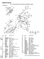
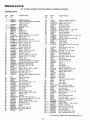
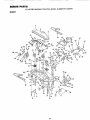
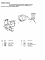
REPAIR
PARTS
GT 18 TWIN GARDEN
TRACTOR--MODEL
NUMBER
917,255910
ELECTRICAL
_35
34
48
43
44
10
18
D
9
!25
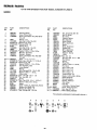
KEY
NO.
PART
NO.
DESCRIPTION
STD365410 * Switch
KeySet - Ignition
'_S-T4;_654_0"
11151000
Washer- Lock- Int, Tooth 5t8
3258J
Nut - Hex 5/8- 32
5
105791X
Ammeter
6
I05382X
Switch- Light
7
913BR
Battery
8
7603J
Tray - Battery
9 C_,,W_.!00541K
Tube - Drain - ,,-,_,_ '3(_,.',_)
10
6999R
Clamp- Hose
11
2008J
Solenoid
12
10090400
Washer- Lock 1/4
o 13
STD54!225
*Nut- Hex-Jam I/4- 20
17190408
Screw - Hex Washer Thread Cutting
1/4 - 20 x !/2
Switch - Interlock
_'_J15
104445X
'_
16
71031008
Screw- Hex Washer No. 10- 32 x 1/2
17
73951000
Nut- Keps No. 10 - 32
!8
106315X
Diode Assembly
Harness - Wire,- _=,_4_to53_ 6 _£
19r_y_,.-_105387 X
2O
4152J
Bulb * Headlight
21
STD380300
* Fuse - 30 Amp
22
74610628
Bolt - Hex 3/8 - 24 x 1 - 3/4
23
STD523707
*Bolt - Hex 3/8- 16 x 3/4
_-_- 24
4207J
Cable - Ground
11050500
Washer- Lock- Ext. Tooth 5/16"
_Jo -- 25
4021J
Switch- PTO
0_'_ 26
4022J
Nut. Hex
._x_ 27
- 27
KEY
NO..
PART
NO.
28
4799J
29
719J
30
51J
31
5t15J
32
106553X
33
106316X
34
106367X
35
106366X
36
19132203
37
STD651137
38
72240460
39
11030400
4O
STD54!625
41
102476X
42
STD522507
43
STD55t025
44
STD541025
45
STD551125
46
!05819X
47 ()J_t_&I06617X
48 _v_,__106580X
--I01539X
-106t55X
_\_
-- 1
._k$_3
*STANDARD
-
DESCR IPTION
Cable - Battery
Cover -Terminal
Cover - Terminal
Cable _ Starter
Cover - Cable
Clutch - Electric
Spacer - Clutch
Stop - Clutch
Washer
*Washer - Lock 3/8
Bolt- Carriage 1/4- 20 x 7.1/2
Washer = Lock- IntJExt. Tooth 1/4
*Nut- Wing 1/4- 20
Guard - Terminal
* Bolt - Hex !/4- 20 x 3/4
*Washer 9/32 x 5/8 x 16 G&
*Nut- Hex t/4 - 20
*Washer - Lock 1/4
Harness=-Ignition
Clamp, Hose
Kit, Replacement Fuseholder
Sheet, Instruction, Tractor 15 o Slope
Manual - Owners
HARDWARE--PURCHASE
LOCALLY
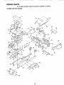
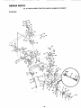
REPAIR
PARTS
GT 18 TWIN GARDEN
TRACTOR.-MODEL
NUMBER
917.255910
CHASSIS AND ENCLOSURES
61
:M
y
M
63
12
13
71
52
18
39
27
27
27
38
67 E
'59
- 28-
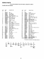
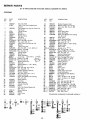
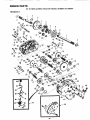
REPAIR PARTS
GT 18 TWIN
GARDEN
TRACTOR*_MODEL
NUMBER
917,255910
CHASSIS AND ENCLOSURES
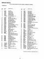
KEY
NOo
PART
NO
1
2
3
4
5
6
7
8
9
10
11
12
13
14
15
16
105515X
105516X
105529X
105536X
73680500
19171912
STD551150
STD525010
t05513X
73680600
t05507X
t06202X
I05801X
STD523797
105567X
17490608
17
17490612
18
105511X
19
105514X
20
1055t2X
21
19132012
22
105531X
23
I05509X
24
106020X
25
105965X
26_,,_106082X
27
6999R
28
5277J
29
3008,1
30
I05465X
3!
105466X
32
105464X
33
!05506X
34
106504X
DESCRIPTION
KEY
NO
Seat
Pan Seat
Bolt ° Shoulder
Washer - Spring
Nut- Lock 5/16- 18
Washer t7/32 x 13/16 x 12 Ga.
*Washer- Lock 1/2
*Bolt _ Hex 1/2 - 13 x 1
Bracket - Pivot Seat
Nut- Lock 3/8 !6
Fender
Refector - Taillight
Decal
* Bolt Hex 3/8- 16 x 3/4
Decal - Chassis
Screw - Hex Washer Thread Rolling
3/8- 16 x 1/2
Screw - Hex Washer Thread Rolling
3/8 x 16 x 3/4
Strap - Fender
Clamp - Spring
Spring - Compression
Washer 13/32 x 1 I/4 x 12 Ga,
Nut - Push
Bracket- Fender
Tank Fuel
Cap Fuel
Pad - Spacer - _:_= - GqSJL1
Clamp- Hose
Line - Fuel
Line Fuel
Footrest
LH
Pad o Footrest
Footrest- R H°
Rait- Frame R H
Rait Frame L H
35
36
37
38
39
40
41
42
43
44
45
46
47
46
49
50
51
52
54
55
56
57
58
59
61
62
63
64
65
66
67
68
69
70
71
PART
NO
DESCRIPTION
7982J
74760716
73680700
105520X
I05562X
t0555tX
105494X
I05495X
t06013X
_06087X
brawbar
Bolt- Hex 7/16- 14 x 1
Nut Lock 7/t6
14
Pane_ Side R H
Decal
Panel Side L H.
Bracket Pivot Frame R Ho
Bracket Pivot Frame - L H.
Hood
:'Shield_Heat_ Frbn_;
STD551125 *Washer- Lock 1/4
STD541025 *Nut- Hex 1/4 20
I05526X
Gril{
105492X
Bracket Pivot Grill- Roll
I05493X
Bracket Pivot Grill Loll
106003X
Lens R H
106004X
Lens LH
106006X
Bezel _ L H.
106005X
Bezel R.Ho
11030400
Washer Lock - lnt,/Ext, Tooth
10609tX
Hinge R H
106090X
Hinge L H
105524X
Strap - Grill
105571X
Decal - Hood - RHo
105570X
Decal- Hood Loll
105569X
Decal Fender
106225X
Decal - Drive Belt Schematic
4900J
Decal Clutch/Brake
3645J
Bushing
87103
Stem - Tank, Fuel
105806X
Decal - Grill
105568X
Decal Grill (Stripe)
19131416 •
Washer 13/32 x 7/8 x 16 Gao
*STANDARD
A
C
D
E
F
17 (_21
@4
G
H
36
_10
@46
J
_47
HARDWARE_ PURCHASE
K
_47
L
M
17
14
_47
lo
70
37
- 29-
t_10
1/4
LOCALLY
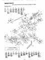
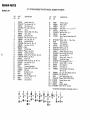
REP M
PAaT8
GT 18 TWIN GARDEN
GROUND
A
TRACTOR-MODEL
NUMBER
917.255910
DRIVE
B
10
_
14
(_
15
d#11
A
49
U
9
D
69
l
71
59
SparkOPTtONAt.
Attester Muffler
106664X
EQUIPMENT
J
K
L
M
N
1
O
P
Q
R
70
@_11
_82
- 30 -
U
•
RmPAURPARTS
GT 18 TWIN
GROUND
KEY
NO_
GARDEN
TRACTOR-MODEL
NUMBER
917.255910
DRIVE
PART
NO.
DESCRIPTION
1 J'_-106B37X
2
106035X
Bracket, Support
Engine, 18 H.P., Model No. 422437
Type Noo0721-0t
3
13240200
Elbow, Street
4 _,_
9767H
Valve, Oil Drain
5 ,_--_-:_:t3260302; :: ; B_sliing
6
7
105574X
Muffler, L H
8
I05575X
Muffler_ R.H.
9
8545J
Gasket, Muffler
10
74570412
Screw, Socket Hdo, t/4 - 20 x 3/4
1t
STD551125 _Washer, Lock, 1/4
12
5266J
Base, Engine
13
STD523707 *Bott, Hex, 3/8 - 16 x 3/4
14
STD523112 *Bolt, Hex, 5/16- 18x 1 - 1/4. Gr 5
15
STD551131 *Washer, Lock, 5/16
16
STD541031 *Nut t He×, 5/16 - 18
17
73680600
Nut, Lock, 3/8- 16
18
I01343L
Pulley, Ground Drive
19
STD551137 *Washer, Lock, 3/8
20
19131614
Washer, 13/32 x 1 x 14 Ga..
2t
105599X
Bracket, Drive, Mule
22
72110608
Bolt, 3/8- 16 x 1
23
106000X
Bracket, V-Pulley, Drive, Mule
24
19131612
Washer, 13/32 x I x I2 Gao
25
101344L
Pulley, Idler
26
5255J
Bracket, Idler, Flat
27
I06048X
Guard, Belt, Mule Drive, Flat Idler
28
106023X
Guard, Belt, Mule Drive, V-idler
29
72_110616 _::i _B_|t:i Ca_i:_3/8 :__6 _' 2
30
STD533707
*Bolt, Carro, 3/8_ 16 x 3/4
3!
2083R
Idler, Flat
32
STD551037
*Washer, 13/32 x 13/16 x 16 Ga,
33
101347L
Bracket, Flat Idler
34
STD533710
*Bolt, Carr, 3/8- t6 x I
35
STD541037
*Nut, Hex, 3/8- 16
36
105592X
Bracket, Clutch w/Bearing (Inco Key
No 106)
37
207J
Washer, Hardened
36
12000039
Klip Ring
39
8846R
Idler, Grooved
40
STD523715
*Bolt, Hex, 3/8- 16x 1 - 1/2
41
73930600
Nut, Lock, 3/8- 16
42
101355X
Spr_ng, Extension
43
STD570907
*Pin, Cotter, 3/32 x 3/4
44
101356L
Rod, Clutch
45
104366X
Idler, Flat
46
STD523720 *Bolt, Hex, 3/8- 16 x 2
47
19131413
Washer, 13/32 x 7/8 x 13 Ga,
48
I05597X
Retainer, Belt
49
104577X
Adapter
50
STD5237t0
"Bolt, Hex, 3/8- 16 x 1 Gr. 5
51
17190512
Screw, Hex, Slotted, 5/16 - 18 x 3/4
52
t05500X
Retainer, Belt, Lower
53
19131312
Washer, 13/32 x 13/16 x 12 Ga.
54
101345M
Rod, Shift, Hi-Lo
55
!05598X
Bracket, Rod, Shift
56
100196K
Knob
57
73680500
Nut, Loc*k, 5/16 _ 18
58
STD571810 *Pin, Cotter, 3/16 x 1
59
10!342N
V-Belt
KEY
NO.
PART
NO.
60
61
62
63
64
65
66
67
68
69
70
7t
72
73
74
75
76
7952J
74760716
STD551143
101341M
9204H
104375X
19252016
STD571812
106021X
5693J
17720406
!04596X
11050600
STD541137
8893R
677A637
74370612
DESCRIPTION
Bracket, Support, Transa_le
Bolt, Hex, 7/16- 14 x 1
Washer, Lock, 7/16
Pulley, Transaxle
Nut, Lock, 1/2_ 20
Shaft, Foot Pedal
Washer, 25/32 x 1 - 1/4 x 16 Ga.
Pin, Roll, 3/16 x 1 - 1/4
Spring, Extension
Control, Throttle
Screw, Hex, Thd. Cut, 1/4 - 20 x 1/2
Control, Choke
Washer, Lock, Ext. Tooth, 3/8
*Nut, 3/8 - 24
Cover, Pedal
Bracket, Brake
Screw, Mach, Unct. FIo Hd., 3/8 16 x 3/4
77
74760614
Bolt, Hex, 3/8 - 16 x 7/8
78
7920J
Band, Brake
79
72140405
Bolt, Cam, 1/4- 20 x 5/8
80
STD54t025
"Nut, Hex, 1/4- 20
81
7229J
Guide, Rod, Brake
82
!685H
Nut, Lock, 5/16- 18
83
STD5331 t0 *Bo!t, Carro, 5/16 - 18 x 3/4
84
5308J
Rod, Brake
85
7241J
Spring, Compression
86
73530600
Nut, Lock, 3/8 - 24
87
t00604K
Yoke
88
5102J
Pin, Clevis
89
71673
Cap, P_unger
90
8000J
Rod, Parking Brake
91
19111216
Washer, 11/32 x 3/4 x 16Gao
92
634A692
Bushing and Wheel Hub
93
7563R
Washer, Thrust, Axle
94
12000034
Klip Ring
95
1304H
Bolt, Hub
96
106277X
Wheel, Rear
97
I05588X
Tire, Rear
7154J
Tu be, Tire (Not furnished)
98
65139
Val re, Tire
99
59192
Cap, Valve
100
214J
Drum, Brake
10t
STD541410 *Nut - Lock No. 10- 24
t02
633A109
Gear Shift Lever Assembly
103
2228M
Key, Woodruff
t04
4186J
Spacer, Transaxle
105
74760740
Bolt, Hex, 7/I6- 14 x 2- 1/2
106
1013501<
Bearing- Idler
107
7192J
Tie - Cable
108
61159
Knob - Throttle Control
109
9858M1
Key - Woodruff
1t0
5304J
Actuator - Switch, Interlock
111
74321016
Screw- Fin 10- 24 x 1
112 ,_-*_ _3280252: : Nipple, :Pipe
113,'_,-__:_'_19i320i2 .... Waslier 13_32 x 1- 1/4 x 12 Ga.
! 14 _- .'-J104601X
Bracket - Interlock
115_,,_. J STD522507 *Bolt- Hex 1/4- 20 x 3/4
1t6_ _'_:_ 73680400
Nut - Crownlock 1/4- 20
117_'.,"_'=!-104758X
Cap- Hub, Rear
118:;_!,:t,;,J19131210
Washer 13/32 x 3/4 x 10 Gao
119 _;!_/._.-_73680700
Nut. Crownlock 7/16 - 14
*STANDARD
-31
HARDWAREs-PURCHASE
LOCALLY
REPA|R
PARTS
GT 18 TWIN GARDEN
TRACTOR--MODEL
NUMBER
917.255910
STEERING
53
._52
21_,,_
'_'39
37
-40
75
M
L
/ 48
71
78
41
32
56
30
63
29
17
13
15
82
i81
83
2O
54
21
22
22
26
26
21
22
27
- 32 -
t85
RE PAiR
PARTS
GT 18 TWIN
GARDEN
TRACTOR_-MODEL
NUMBER
917,255910
STEERING
KEY
NO.
PART
NO.
t
---
106230X
8134H
2
106228X
DESCRIPTION
3
4
5
6
7
8
9
10
11
12
13
14
15
16
17
18
19
20
2!
278H
9040H
106045X
6266H
12000029
5284J
STD523707
73680600
674A244
1309H
5298J
74781044
STD551162
STD54t062
6855M
106046X
102997X
7e24_;3J-STD551137
22
23
24
25
26
27
28
29
30
31
32
33
STD541137
- 5292J
677A607
19292016
7990J
STD523720
73510600
102439X
104239X
72110608
t01274N
17490612
34
35
36
37
38
39
102458X
12000034
100713N
100711L
678H500
74040616
40
4t
42
43
I06014X
9038R
105519X
105536X
A
B
C
Tire, t6 x 6,50
Tube, Front (not furnished
tractor)
Front Wheel (inc. Key No.
Key No. 4)
Fitting, Grease
Bearing
Spindle, R.H_
Bearing, Thrust
Klip Ring
Bracket, Axfe
*Bo_t- Hex 3/8 - 16 x 3/4
Nut, Lock, 3/8- t6
Axle t Front, (inc. K_y No.
Bearing
Tube, P_vot, Axle
Bolt, Hex 5/8- 11 x 2- 3/4
*Washer, Lock 5/8
*Nut, Hex 5/8- 11
Fitting, Grease
Spindle, LH_
Sector Assembly
Link, Drag
_'_._%'_
*Washer, Loci< 3t8
KEY
NO.
with
3 and 2 of
12)
Gr. 5
P_-_"J_,
_=,-p,._5
*Nut, Hex 3/8- 24
_"
_"
Bushing, Beilcrank
t_)_''_'-_
Bellcrank
Washer 29/32 x I - I/4 x 16 Ga.
Rod, Tie
*Bolt, Hex 3/8 - 16 x 2 Gro 5
Nut, Keps 3/8 - 16
Bracket, Support, Steering
Bearing, Flanged
,Bo]t, Carr. 3/8- t6 x 1 Gr. 5
Support, Steering
Screw, Hex Washer Thd, Ro!!_ng
3/8 - 16 x 3/4
Shaft, Steering
Klip Ring
Wheel, Steering
Adapter, Steering
Washer
Bolt - Hex Slotted Washer Hal.
3/8- 16 x 1
Sleeve, Steering
Bearing
Dash, Lower
Dash
D
PART
NO.
44
i45
46
47
48
49
50
51
105525X
19131416
,-_-!!05_,
106486X
106002X
106042X
105572X
17240408
52
53
54
55
56
57
58
59(_I,
60
61
62
63
64
65
66
105810X
I00710L
STD525020
73680800
19172610
t06385X
677A451
L10436 IX
STD533720
19131413
STD541037
5213J
105589X
STD533110
19t 1t610
67
73680500
68
7985J
69
I06199X
70
I05487X
71
4043J
72
65139
73
59192
74
106198X
75
105565X
_76
!06615X
78
8022J
79
8921R
80
8922R
81
7919J
82
73700600
83
STD541337
84
STD533107
85
19252016
87_JJ- 19132012
88_.__o-1 74930516
89_,._._ STD541031
90_ '_ 104757X
*STANDARD
E
-33-
DESCRIPTION
Bracket, Support, Dash
Washer 13/32 x 7/8 x 16 Ga.
Boit- Cam 3/8 - t6 x 2 - 3/4
Spacer
U-Clip
Cover. Gate, Shift
Decal. Shift Gate
Screw. Hex Washer Thd. Cutting
1/4 * 20 x I/2
Decal. Insert
Insertm Steering Wheel
*Bolt - Hex 1/2 - 13 x 2
Nut. Lock t/2 - 13
Washer 17/32 x 1 - 5/8 x 10 Ga..
Bracket. Idler
Pulley, Idler
Spring _ vo_.s qfg0S
*Bolt, Carriage 3/8- 16 x 2
Washer 13/32x 7/8 x 13Ga,
*Nut- Hex 3/8- 16
Bracket, Frame Front
Guard, Belt, Engine
* Bolt - Carriage 5/16 - 18 x 1
Washer 11/32 x 1 x 10 Ga.
Nut, Lock 5/16- t8
Support, Battery
Decal - Caution
Screw, Special
Washer
Stem, Valve
Cap, Valve
Decal, Dash, Instruction
Decal, Instruction
Pin, Mounting, Idler Bracket
Plug - Dash
Joint - Tie Rod - R°H.. Thread
Joint - Tie Rod - LH. Thread
Rod- Tie
Nut - Hex Jam 3/8- 24_L;H.
*Nut - Hex Jam 3/8 o 24
*Bolt _ Carriage 5/16 - 18 x 3/4
Washer 25/32 x t - 1/4x t6Ga,
Washer 13/32 x t - 1/4x 12Ga.
Bolt. Hex 5/!6 _ 18 x 1
* Nut_ Hex 5/16- 18
Cap _ Hub, Front
HARDWARE-PURCHASE
LOCALLY
REPAM
PART8
GT 18 TWIN GARDEN
MOWER
TRACTOR-MODEL
NUMBER
917.255910
5o
L ! FT
54
17
1!
14
26
24
23
11
!
46
43
49
5g
60
58
33
41
40
45
44
39
REPAIR
PART8
GT 18 TWIN GARDEN
MOWER
TRACTOR--MODEL
NUMBER
917.255910
LIFT
KEY
NO.
PART
NO.
DESCRIPTION
1
2
3
4
5
6
7
8
9
t0
!1
12
13
14
15
16
17
18
19
20
21
22
23
24
25
26
27
28
29
3O
31
100734K
STD541237
1063!8X
STD570907
2876H
19131016
105505X
105559X
STD523107
73680500
105573X
STD522505
73680400
Handle. Adiust, Lift
*Nut, He× Jam, 3/B - 16
Rod, Adiust, Lift
*Pin, Cotter, 3/32 x 3/4
Spring
Washer 13/32 x 5/8 x 16 Ga.
Cover_ Access
Shield, Heat, Rear
*Bolt, Hex, 5/16 - 18 x 3/4
Nut, Lock, 5/16 - 18
Brace, Heat Shield
*Bolt. Hex, 1/4- 20 x 1/2
Nut, Lock, 1/4 - 20
106504X
STD55!13t
105040X
74750806
STD551108
105041X
STD511005
73631000
105633X
6519J
19151216
12000037
7594J
7901J
73900400
7596J
105503X
*Washer, Lock, 5/16
E}racket, Fuel Pump
Screw, Sl. Hex Hd. No. 8 - 32 × 3/8
*Washer, Lock No. 8
Pump, Fuet
*Screw, Hex Hd. No. 10 - 24 x 1/2
Nut, Lock No. 10- 24
Shaft, Lift
Trunnion, Stop Depth
Washer 15/32 x 3/4 x t6 Ga.
Kiip Ring
Bracket, Lift, L.H.
Bolt, Shoulder
Nut, Hex Flange 1/4 - 20
Link, Lift, L.H,
Link, Lift, R.H.
Bushing,
KEY
NO.
PART
NO.
DESCRIPTION
32
4939M
33
I05630X
34
t05622X
35_-,_,_*_106644X
36
105723X
37
STD523710
38
106019X
39
74570616
Retainer, Spring
Washer, Nyion
Lever, Lift
Rod, Detent _c-,3
Io_G,._QX
Plunger, Lever
*Bolt- Hex 3/8 - 16 x 1
Grip, Handle
Screw.. Cap, Hex Socket Head, 3/8 16xl
40
STD551050 *Washer 17/32 x 1 _t/16 x 13 Ga.
41
9135R
Retainer Spring
42
I05429X
Arm, Suspension
43
1054!3X
Stud, Pivot Center
44
STD551150
*Washer, Lock, 1/2
45
STD541050 *Nut, Hex, t/2 - 13
46
105501X
Bracket, Suspension, Mower
47
STD533707 *Bolt, Carriage, 3/8 - 16 x 3/4
48
73680600
Nut. Lock. 3/8 - 16
49
674A247
Spring - Ass v, - Assist, Lift
50
105589X
Guard, Belt. Engine
51
STD533107 *Bolt, Carriage, 5/t6 - 18 x 1
52
19131612
Washer 13/32 x 1 x 12 Ga.
53
105526X
Panel, Side, R.H.
54
105527X
Panel, Side, L.H.
55
17490608
Bolt, Hex Washer Thd, Roiling,
3/8 - 16 x 1/2
56
73800600
Nut, Lock. Hex w/_Nasher, 3/8 - 16
57
STD541037
*Nut, Hex 3/8.16
58
5328J
BoIt- Adiust, Spring, Assist
59
STD551037
*Washer 13/32 x 13/16 x 16 Ga.
60 P_L_678H445
Bracket, Spring - Assist
6!_,
_- 106012X
Spacer
62 _-:_ 1(]4_0!_X
__Bracket - Switch
63 _\,_._=,_STD522507 * Bolt - Rex i/4- 20 x 3/4
Snap
*STANDARD
A
B
C
13
_)
D
16
E
F
(3
H
J
K
_21
_28
_47
_51
?'55
_37
2= =g
@4s
HARDWARE-PURCHASE
L
_
63
LOCALLY
REPAIR P_T8
GT 18 TWiN GARDEN
TRACTOR--MODEL
NUMBER
917.255910
MOWER
G
51
47
47
/
35
38
12
37
\
6O
44 55
45
4O
71
56
51
D
35 35
34
_!/6
18
17
15
31
17
16
15
16
17
- 36 +
32
49
a ,RT8
GT 18 TWIN GARDEN
TRACTOR-MODEL
NUMBER
917.255910
MOWER
KEY
NO.
!
2
3
4
5
6
7
8
9
10
11
12
13
14
PART
NO.
106579X
106022X
17490508
7631J
72110505
STD551131
STD54t031
8418J
721,48506
1685H
STD551031
105194X
106038X
17490612
15 _-_,,,J_0
_106635X
16
STD623715
17
STD551137
t8
19132012
t9
674A213
20
7834J
21
7835J
22
72110522
23
19111610
24
I02403X
25
STD523715
26
STD541037
27
104361X
28
STD523112
29
19111216
3O
8438J
31
106224X
32
I05448X
33
t05449X
34
STD533707
DESCRIPTION
KEY
NO.
PART
NO.
DESCRIPTION
35
73680600
36
105453X
37
5565J
38
4939M
39
4898H
40
105455X
41
105433X
42
105430X
43
105434X
44
105436X
45
105441X
46
78850
47
9135R
48
106381X
49
STD541050
50
74760622
51
105435X
52
3720R
53
12000039
54
19171612
55
105440X
56
105456X
57
105460X
58
105461X
59
105457X
6O
73680500
62
19111016
63
105895X
64
106551X
65
105896X
66
106520X
68
5846R
69
3713J
70_'_-6224J
71A_,ko_.73680800
Housing, Mower
Cover - Drive, Deck
Screw - Hex Washer Thd. Rot! 5/t6 18 x 1/2
Runner, L.H.
Bolt, Cam 5/t6- 18 x 5/8
*Washer-Lock, 5/16
*Nut-Hex 5/16 - 18
Runner, R,H.
Bolt, Carr. 5/16 - 18 x 3/4
Nut, Lock 5/16- 18
*Washer 11/32 x 11/16 x 16 Ga.
Mandrel - Secondary
Mandrel - Primary
Screw. Hex Washer Th& Roll 3/8 t6 x 3/4
Blade -_,s
l_otq_;_'_
*Bolt ° Hex, 3/8 = 24 x 1 _ 1/2 Gr. 5
*Washer-Lock, 3/8
Washer 13/32 x 1 - 1/4x 12Ga.
Arm Assembly, Idler
Liner, Bearing
Bearing
Bolt, Carriage 5/16 - t8 x 2-3/4
Washer11/32x
l x10Ga.
Pulley, Idler
*Bolt - Hex 3/8- 16x 1 - 1/2
*Nut- Hex 3/8- 16
Spring
*Bolt- Hex 5/16- 18 x 1 - 1/4 Gr. 5
Washer tl/32 x 3/4 x 16Ga.
Spacer
Decal o V-Belt, Dr., Schematic, Mower
Bracket, Gao Wheel, R,H.
Bracket, Ga. Wheel, L,H,
*Bolt, Carriage 3/8- 16 x 3/4
Nut, Crownlock 3/8.16
Bar, Ga, Whee}
Pin, Clevis
Retainer, Spring
Bolt, Shoulder
Wheel, Gauge
Brkt., Suspension
Spacer
Brace, Suspension
Parallel Link
Brkt,, Suspension
Decal - Warning
Retainer- Spring
V-Belt
*Nut, 1/2- 13
Bolt, Hex 3/8 _ t6 x I - 3/8
Pin, Release
Spring
Ring, Klip
Washer 17/32 x 1 x I2 Gao
Pin, Clevis
8rkt., Outer, RoH_
Brkt., Inner, R.H,
Brkto, Inner, L.Ho
Brkt°, Outer, L.H.
Loeknut 5/1.6- t8
Washer 11/32x 5/8 x 16Ga.
Shield, Deflector
Spring, Deflector
Bracket, Deflector
Rod, Hinge
Push Nut
Instruction. Caution Decal
Decal - Safety Standard
Nut - Hex 1/2- 13
*STANDARD
A
B
C
D
E
9
35
O,o
- 37 -
HARDWARE--PURCHASE
F
50
35
G
14
_
7
LOCALLY
REPAmR PARTS
GT 18 TWIN GARDEN
TRACTOR-oMODEL
NUMBER
917.255910
TRANSAXLE
3
7
14
61
59 5_
54
73
69
70
"
49
40
41
24
REPAmR PARTS
GT 18 TWIN
GARDEN
TRACTOR--MODEL
NUMBER
917.255910
TRANSAXLE
KEY
PART
NO,,
NO,
1
2
3
4
5
6
7
B
4197R
6845R
4199R
4216R
4215R
4217R
6256H
74020652
9
I0
11
12
13
14
15
16
17
18
19
20
21
22
23
24
25
26
27
28
29
3O
31
7392M
6272H
4985R
6266H
42t2R
4196R
6276H
633A63
8118M
8740H1
6217H
4218R
6252HI
7810H
4986R
7393R
992Rt
6216H
6262H
101416X
6269H
5655H
101414X
32
33
34
35
36
37
38
39
6277H
4225R
7396H
4198R
4200R
7395H
6275H
633A64
40
41
42
45
46
47
13060400
13200400
13280424
6271H
13060200
74780524
48
10140500
DESCRIPTtO"J
Axle Shaft
Retaining Ring
Final Drive Gear
Differential Gear
Differential Pinion
Differential Carrier
Axle Thrust Washer
Hex Bob 3/8 ..24 x 3- 1/4
(t" Thread Length)
Steel Ball
Spring Shift Fork Detent
Shift Fork, High - Low Range
Thrust Bearing Race
4th Reduction Pinion
3rd Reduction Gear Shaft
Snap Ring ..Crescent Type
High - Low Range Gears
Needle Bearing
Sintered Iron Bearing
Shift Fork Shaft, High - Low Range
Differential Pinion Spacer
Differential Pinion Bushing
Gripco Centerlock Nut 3t8- 24
Shift Fork - t..Ho
Oil Seal
Sintered Iron Bearing
Shift Fork Shaft
Shift Fork - Roll
Shift Shaft, High. Low Range
Oil Seal
Pressure Relief Valve
Gearcase, Reverse idler Shaft and
Bearings. R.Ho (Inc. Key NoJs. 17,
18, 25, 33, 50, 63, 76, 77 and 82)
Dowel Pin
Needle Bearing
Thrust Bearing Race
4th Reduction Gear Shaft
4th Reduction Gear Spacer
Thrust Bearing Race
GearcaseGasket
Gearcaseand Bearings - L.H.
(Inc. Key No's. 18.25, 49. 50 (2),
51 and 52)
Pipe Plug 1/2 o 14 N.P.T.
Elbow 90 °, 1/2. 1/4 NPoTo
Pipe Nipple 1/2 - 14 NPT.
Oil Seal
Pipe Plug 1/4 - 18 N.P.To
*Hex Bolt 5/16 - 18 x I ..1/2
Grade 5
Lockwasher 5/16 Extra Heavy
KEY
PART
NO,
NO
49
50
51
52
53
54
55
56
57
58
59
60
61
62
63
64
4895H
4222R
1529R
8119M
4220R
4209R
4213R
4442R
4195R
4214R
4194R
752BR
4208R
4207R
7398H
4203R
65
66
67
68
69
70
71
4204R
2698J
4926H
4205R
4206R
1370H
633A69
72
73
74
75
76
77
78
79
80
81
82
83
84
85
86
87
88
89
90
91
92
93
94
95
96
97
98
208J
420t R
12000002
1153R
7392H
3990H
73220500
1167R
73360700
6270H
7384H
t00196K
5384J
297BJ
633A85
8739H!
4924H
19151516
8t05R
19181511
75J
6274H
76020412
10040500
74760514
633A109
101444X
"STANDARD
- 39 -
DESCRIPTION
Needle Bearing
Needle Bearing
Needle Bearing
Needle Bearing
Thrust Bearing Race
3rd Reduction Pinion. Low
4th Reduction Gear
3rd Reduction Pinion Spacer
2nd Reduction Gear Shaft
Final Drive Pinion
1st Reduction Gear Shaft
1st Reduction Shaft Spacer
3rd Reduction Pinion- High
2nd Reduction Gear
Needle Bearing
Low Speed Gear and 2nd Reduction
Pinion Cluster
Reverse Gear
Key oHi -Pro 1/8 x 17/32
Snap Ring - CrescentType
intermediate Speed Gear
High Speed Gear
Thrust Bearing Race
Intermediate and High Speed Cluster
Pinions
Input Shaft
Low Speed Pinion
E-Ring
Reverse Idler Gear
Reverse Idler Thrust Washer
Needle Bearing
*Hex Nut 5/16 ,,18
Sealing Washer
Hex Jam Nut 7/16 - 20
Oil Seal
Reverse Idler Shaft
Control Knob
Gear Shift Lever- Bent
Gear Shift Cap
Gear Shift Ball Cover and Pin
Shift Lever Guide Ball ..Keyed
Spring
Washer t5/32 x 15/16 x !6Go,
Shift Mechanism Seal
Washer 9/16 x t5/t6 x t2 Go,
Gear Shift Gate and Reinforcement
Shift Ball Cover Gasket
Cotter 1/8 x 3/4
* Lockwasher 5/t 6
*Hex Bolt5/16- 18 UNC x 7/8
Gear Shift Lever Ass'y,
Transaxle Assembly LessBrake Drum
& Shift Lever
HARDWARE,..rpURCHASE
LOCALLY
REPAHR PARTS
GT 18 TWIN GARDEN TRACTOR--MODEL
NUMBER 917.255910
ENGINE-MODEL
NUMBER 422437, TYPE NUMBER 0721-01
CYLINDER,
CRANKSHAFT
AND ENGINE
BASE GROUP
52
3
38
16
17
62
66
13
29
27
- 40 -
REPAIR
PARTS
GT 18 TWIN
GARDEN
ENGINE_-MODEL
CYLINDER,
CRANKSHAFT
KEY
NO,
PART
NO.
I
2
3
4
5
8
7
8
9
10
11
tl
11
12
13
t4
15
16
17
18
19
394900
391086
212461
212462
270984
270983
393243
393153
27803
93394
270882
271145
271148
93113
93111
91084
394430
394535
291675
93847
394955
I9
19
19
20
20
20
20
21
394956
394957
394958
394959
394960
394961
394962
394023
22
23
260924
299691
23
24
25
26
27
28
29
30
31
32
33
34
391286
394306
223053
92909
390420
65906
26828
221596
292260
93630
261368
212337
AND
ENGINE
TRACTOR-MODEL
HUMBER
BASE
422437,
917.255910
NUMBER
0721-01
GROUP
DESCRIPTION
Cylinder Assembly
Seal- Oil
Head- Cylinder No. t
Head- Cylinder No. 2
*Gasket ..Cylinder Head No 1
*Gasket - Cylinder Head No, 2
Breather Assembly NoD 1
Breather Auembly No, 2
*Gasket .. Valve Cover
Screw., Scm
°Gasket ,. CrankcaseCover t/64" Thick
"Gasket _ Crankcar_ Cover °008" Thick
°Gasket - CrankcaseCover ,089" Thick
Screw ,,Cylinder Head (2., t5/16" long)
Screw- Cylinder Head (1 !5/16" long)
Rug,, Oil Drain
Crankshaft
Cover Assembly- Crankcase
Seal. Oi!
Screw- CrankcaseCover Mtg, Sam
Piston Assembly • Standard (Inc,
Key No_s, 20 & 22)
Piston A_embly ...010" O.So
Piston Assembly - ,020" O,,S,
Piston Assembly - °030" O,So
Ring Set- Piston, Standard
Ring Set., Piston- ,010" O.S,
Ring Set, Piston- ,020" O,S.
Ring Set- Piston- °030" O,&
Dipstick and Tube Assembly (inc.
Key No's 44, 45 & 46)
Lock- Piston Pin
Pin Assembly ..Piston - Standard
(Inc. Key NOD22)
Pin Assembly. Piston .. ,005"O.S
Rod Assembly - Connecting
Dipper- Connecting Rod
Screw. Connecting Rod
Valve Exhaust
Spring, Intake Valve
Spring ,.Exhaust Valve
Retainer • Intake Valve
Rotocoil ,,Exhaust
Retainer ..Exhaust Valve Rotocoil
Tappet ,,Valve
Gear. Cam
NUMBER
TYPE
KEY
NO
PART
NO,
35
36
37
38
39
40
271316
296004
394348
89838
220883
394539
41
42
43
44
45
46
47
48
49
50
51
52
53
54
55
56
57
58
59
60
61
62
63
54
65
66
67
68
69
70
71
72
73
74
90576
231174
280180
394014
68838
392782
93783
223055
394391
270981
222700
93053
93851
394396
66538
93448
222698
220863
222773
261363
393606
393741
231218
210940
261463
261559
391115
230318
92791
93722
261528
92268
261623
261560
DESCRIPTION
Foam Seal. Governor Shaft
Pipe. Fuel {Inc. Key No. 52)
Gear. Governor
Wrench - Spark Plug
Washer ..Gov. Crank (inside)
Plug. Spark (Resistor) (2 ,.3/8 high- 60
mm)
Nut- Hex 8- 32
Terminal
Grommet _ insulator
Cap and Dipstick ,_Oil Filler
Sealo Filler Tube
Tube° Oil Filler
Screw ,,Hex Hd_
Trough - Dipper
Base. Engine
"Gasket, Engine Base
Baffle. Air
Clamp° Fuel Pipe
Retainer. E-Ring
Crank • Governor
Elbow- Spark Plug
Plug. Hex Socket
Key- Flywheel
Washer
Washer - Thrust
Gear° Timin_
Seat Assay,and Retainer
Bearing,, Ball (P.T.O. side)
+Guide. Exhaust Valve
+Seat- Exhaust Valve (Standard)
+Seat _.Intake VaNe (Standard)
Lower Bushing- Gov_
Wire ,,Ground
Connector _ Fuel Pipe
Washer. Lock Shakeproof
Terminai ,,
Spade
Valve,, Intake
Washer
+ Bearing - Cyiinder
Upper Bushing - Governor
*inc,, in Gasket Set - 394501
+Special Too{s required to install
R_PAIR PARTS
..........
GT 18 TWIN GARDEN
ENGINE..M
TRACTOR.
ODEL Nit InA_,,,,,,,._
"MODEL NUMBER
"',==H 422437, TYPE
AIR CLEANER-CARBURETOR
GROUp
NUMBER
34
55
917.255910
0721-01
$ EPABR PARTS
GT 18 TWIN GARDEN TRACTOR-MODEL
NUMBER
ENGINE-MODEL
NUMBER 422437, TYPE NUMBER
AIR CLEANER-CARBURETOR
KEY
NO.
PART
NO,
1
2
3
280185
280168
_2970
4
5
271412
270B84
0
7
93415
032O8
8
398620
397241
10
11
12
13
212718
231209
282681
03499
14
15
221939
392072
16
9102O
17
18
19
26157
271607
298514
2O
230886
21
22
299098
398619
23
24
25
222010
392673
94152
27
28
28A
29
30
31
93879
231338
280474
222752
212292
93715
917.255910
0721-01
GROUP
DESCRIPTION
KEY
NO.
PART
NOo
Tube - Breather
Tube- Intake
Manifold ASs'y. - Intake
+=Gasket- Carb, Mtg.
*Gasket ° Intake Manifold Mtg.
Screw _Carb_ Mt9. Sere
Sctow - Intake Manifold Mt9, Sam
I
t
Carburetor Ass y. (inc, Key No s_
9, 10, 11, 12, 13, 14, 150t6, 17,
18, t9, 20, 21, 22, 23, 24, 25, 28,
44, 46, 47, 46, 49° 50, 51, 61, 63,
32
33
34
35
36
37
38
39
261444
261531
261729
261563
222807
222828
394324
393846
40
41
222289
93868
64 & 65),
Body Ass y. • Upper Carb. (inc. Key
No's. 10, 13, 18, 23 & 24)
Body- Upper Carb.
BOshing - .Throttle Shaft
+Valve A,'y_- Carb. Idle
Screw- Throttle and Choke Valve
Mtg. Sam
Valve- Throttle
Shaft and Lever° Throttle
Screw _M_h° FiL Hd. 8- 32 x 5/8
Spring- Throttle Adj,
+'Gasket- C_rburetor Body
Float- Carburetor
+Pin- Float Hince
+VaNe, Fuel Inlet
Body - Lower Carb. (Inc, Key No's,
11, 13, 14, 15 & 65)
Valve- Choke
Shaft and Lever, Choke
Screw- Hex Head Sam
10132 x 5/8
Screw- CasingClamp
°Jet - Needle Valve
O-Ring Seal
Body- Air Cleaner
Knob- Air Clemer
Nut- Hex
42
43
44
45
52
53
54
55
56
57
58
59
60
221535
93893
397882
231172
271271
271411
271180
93853
92278
223001
222835
93496
392643
61
62
63
66
67
68
69
70
.....
261560
394018
271013
93892
394358
93053
393815
394501
394502
DESCRIPTION
Link- Governor
Link- Speed _uot
Spring - Governor
Spring- Governed Idle
Bracket - Speed Control
Lever - S_e_ Control
Plate Ass y. Governor Control
Lever Ass y,- Governor (inc. Key
No's. 40, 55 & 56)
Washer
,_rew. Sam
Clamp- Casing
Screw - Sam
Plug (Inc, Key No, 28A)
Bushing - Speed Control
Element - Air Cleaner
+Gasket- Air Cleaner
Washer
Bolt. Governor Lever
Nut oHex 10.24
Cover - Air Cleu_er
Car_ridg_Plate - Air Qearmr
Saew- Sam
Mounting Strap Ass*y., Air Cleaner
(Inc. Key No. 43)
Upper Bushing - Governor
Certridg_- Air Claaxter
+Washer• Choke Shaft
Screw° Sam
Filter- Fuel
Clamp - Fuel Pipe
Fuel- Line (28"} (cut to required length)
Gasket Set
Carburetor Overhaul Kit
* Included in Gasket Set - 394501
+Included in Carburetor Overhaul Kit - 394502
°High Altitude - Jet - Needle
Valve - Part No. 231333
- 43 -
REPAIR
PARTS
....
GT 18 TWIN GARDEN TRACTOR*-MODEL
NUMBER
ENGINE-MODEL
NUMBER 422437, TYPE NUMBER
STARTER
MOTOR
917.255910
0721_01
GROUP
1
2
31
9
11
33
--_
29
28 I_27
23
20
2_23
KEY
NC)_
2
3
4
5
6
7
8
__J
17
PART
NO,
DESCRIPTION
KEY
NO.
PART
NO.
DESCRIPTION
394891
Armature Group (Inc_ Key No_s.
2,3 & 5)
Trigger Coil Assay Magnatron Ignition
Terminaf - Ignition Coils
Screw Armature Mtg Sere
Armature Ass'y.
Flywheel and Ring Gear Ass'y,
Screw _Sere
Diode and Connector Ass_yo
(Dual Circuit)
Stator * Alternator (Dual Circuit_ (Inc_
Key Noo 8)
Gear- Ftywheel Ring (Includes Mounting
Parts)
Nut Flywheel Lock
Fan * Booster
Housing Assembly
Puller- Flywheet (Optional Accessory)
Thru BoJt
16
17
395538
395537
18
394808
Brush Set
Commutator End Cap Ass'y. - Starter
(InCo Key No. 16)
Motor= Starting (Inc. Key No'=. 13,
150 16, 17, 19. 20, 21, 22, 23 & 24)
19
20
21
22
23
24
25
26
27
28
29
31
32
33
34
392747
394860
391135
280104
90366
91162
393254
93754
92674
223008
231247
93808
393362
271174
396865
394970
221798
93381
394988
392956
93621
393537
392595
I0
391362
11
12
13
14
15
22906
212418
393825
19203
94003
.44.
Armature Assembly (Motor)
Drive End Cap Ass y. - Starter
Crutch Ass'y, * Starter
Gear - Starter
Lockwasher
Screw - Hex Hd. - 6/16.18x
1 - I/2"
Kit - Pinion Springt(tnc_ Key No's. 22 & 26
!Roll Pin
Screw- Hex Hd,
Screen = Rotating
Nut - Hex
Screw - Scm
Alternator HarnessAss y.
Gasket - Exhaust
Starter Drive Group (inc. Key No_s,
21, 22, 25 & 26)
RI IR PARTS
GT 18 TWIN GARDEN
TRACTOR--MODEL
ENGINE-MODEL
NUMBER
422437,
TYPE
MUFFLER,
AIR
GUIDE
AND
HOUSING
KEY
NO,
PART
NO.
DESCRIPTION
I
2
3
4
5
222848
222849
93163
392681
93158
Cover - Air Guide
Cover - Air Guide
Screw- Sere
Housing- Blower
Screw. Sere
NUMBER
NUMBER
917.255910
0721-01
GROUP
KEY
NO,
6
7
8
PART
NO,
DESCRIPTION
222847
222846
93777
Shield- Cylinder
Shield - Cylinder
Screw- Hex Hd., (Back Plate
to Cylinder )
Back Plate AssJy_
392934
45 -
SERVICS
NOTES
- 46
I
SIGHT AND HOLD THSS LEVEL
SKY LaNE OR TREE
WITH
®
Operate
your Tractor
up and down the face of slopes (not
greater than 15°); never across the face, Make turns gradu*
ally to prevent tipping or toss of control.
Exercise extreme
caution when changing direction on slopes.
GT 18 TWIN
6 SPEED
S__S
OWNERS
MANUAL
GARDEN TRACTOR
MODEL NO.
917.255910
The Model Number will be found on the Model Plate attached
to the Drawbar. Always mention the Model Number when requesting service or repair parts for your Garden Tractor.
All parts listed herein may be ordered from any Sears Service
Center/Departments
and most Sears Retail Stores.
WHEN ORDERING
REPAIR
FOLLOWING
INFORMATION:
HOW TO ORDER
REPAIR PARTS
•
O
®
O
THE
THE
THE
THE
PARTS,
ALWAYS
GIVE
THE
PART NUMBER
PART DESCRIPTION
MODEL NUMBER
NAME OF MERCHANDISE
If the parts you need are not stocked locally, your order will
be electronically
transmitted to a Sears Repair Parts Distribution Center for "expedited handling",
Sears, Roebuck and Co., Chicago, IL 63684 U.&A.