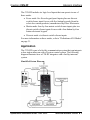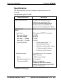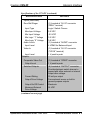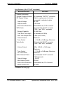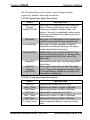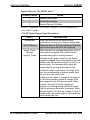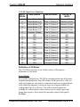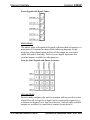
1
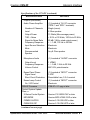
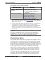
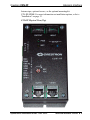
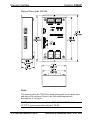
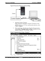
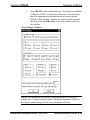
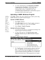
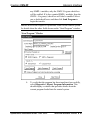
Crestron C2N-IIF Intercom Interface Operations & Installation Guide This document was prepared and written by the Technical Documentation department at: Crestron Electronics, Inc. 15 Volvo Drive Rockleigh, NJ 07647 1-888-CRESTRON All brand names, product names and trademarks are the property of their respective owners. ©2004 Crestron Electronics, Inc. Crestron C2N-IIF Intercom Interface Contents Intercom Interface: C2N-IIF 1 Introduction......................................................................................1 Features and Functions ..........................................................1 Application ............................................................................3 Specifications.........................................................................4 Physical Description ..............................................................8 Industry Compliance............................................................17 Setup...............................................................................................17 Network Wiring ...................................................................17 Hardware Hookup................................................................18 Identity Code .......................................................................20 Installation ...........................................................................23 Programming Software ..................................................................24 Earliest Version Software Requirements.............................24 Programming with SIMPL Windows..................................24 Programming with VisionTools™ Pro-e.............................33 Uploading and Upgrading..............................................................36 Communication Settings......................................................37 Uploading a SIMPL Windows Program..............................40 Uploading a VT Pro-e Project .............................................42 Firmware Upgrade ...............................................................44 Problem Solving.............................................................................46 Troubleshooting...................................................................46 Further Inquiries ..................................................................47 Future Updates.....................................................................48 Return and Warranty Policies ........................................................49 Merchandise Returns / Repair Service ................................49 CRESTRON Limited Warranty ..........................................49 Operations & Installation Guide - DOC. 6235 Contents • i Crestron C2N-IIF Intercom Interface Intercom Interface: C2N-IIF Introduction Features and Functions The Crestron® Intercom Interface (C2N-IIF) is an interface module designed to integrate an intercom door station with a Crestron facility control system. Functional Summary • Integrates intercom door station products from companies like Holovision and Siedle, with Crestron facility control systems • Receives signals from door station microphone and video camera outputs • Input for door bell switch closure • Microphone input with phantom power and volume control potentiometer • Built-in 13-watt audio amplifier with EMI output filters for driving 8 Ohm door station speaker • Line-level audio input (balanced) with output to the door station speaker features electronic volume and tone controls • WAV file playback to door station speaker with electronic volume and tone controls • Storage and playback of up to 30 WAV files (up to 30 seconds total at 8 KHz) • Supplies 12 VDC power at 200 mA to door station camera (if equipped) Operations & Installation Guide - DOC. 6235 Intercom Interface: C2N-IIF • 1 Intercom Interface Crestron C2N-IIF Functional Summary (continued) • Composite video output transmits video signals up to 500 feet over CAT5 cable • Eight switched outputs capable of switching loads up to 50 mA at 24 VDC each (i.e. relays, LEDS, solenoids, etc.) • Six logic-level inputs can be configured to support three different configurations: Essex panel inputs (five) plus one discrete switch closure; four-by-four matrix switch closure plus two discrete switch closures; six discrete switch closures • Mounts with included dual-lock fastener tape, optional screws, or the optional mounting kit C2N-IIF-SPMK that includes a speaker, microphone, and mounting plate for use with Holovision door station products. • Touch-settable ID (TSID) ready The C2N-IIF provides power to a door station camera (12 VDC at 200 mA) and receives signals from a door station’s microphone, video, and bell outputs. If the door station is equipped with a keypad, button presses can also be received and passed on to the Crestron control system. The C2N-IIF is compatible with door station products from companies like Holovision® and Siedle®. The microphone and video signals from a door station are passed through the C2N-IIF’s RJ-45 audio and video connectors for connection to Crestron C2N-IADS30x24 and C2N-IVDS24x24 intercom distribution systems or other Crestron devices that receive CAT5 audio and video. The microphone volume is adjustable via a potentiometer. Audio signals from a Crestron system are received through the C2N-IIF’s RJ-45 audio input, amplified with the built-in amplifier, and sent to the C2N-IIF speaker outputs. The C2N-IIF can store and play up to 30 WAV files (up to 30 seconds total playback for WAV files sampled at 8 KHz) through the built-in 13-watt amplifier. Volume and tone for the audio and WAV signals are adjusted electronically. The C2N-IIF features eight switched outputs capable of switching loads up to 50 mA at 24 VDC each (i.e. relays, LEDS, solenoids, etc.). The loads can be powered by the built-in 24 VDC outputs or other power source. 2 • Intercom Interface: C2N-IIF Operations & Installation Guide - DOC. 6235 Crestron C2N-IIF Intercom Interface The C2N-IIF includes six logic-level inputs that can operate in one of three modes. • Essex mode: five Essex keypad panel inputs plus one discrete switch closure input for use with five-button keypads (found in select door station products) manufactured by Essex Electronics. • Matrix mode: four-by-four matrix switch closure inputs plus two discrete switch closure inputs for use with a four button-by-four button electronic keypad. • Discrete mode: six discrete switch closure inputs. For more information on these modes, refer to “Definitions of IO Modes” on page 31. Application The C2N-IIF is part of a facility communication system that can integrate a door station intercom with a Crestron control system. The following diagram illustrates how a C2N-IIF integrates with a facility intercom system. Simplified System Diagram Operations & Installation Guide - DOC. 6235 Intercom Interface: C2N-IIF • 3 Intercom Interface Crestron C2N-IIF Specifications The following table provides a summary of specifications for the C2N-IIF. Specifications of the C2N-IIF SPECIFICATION Power Requirements Default Net ID Inputs Logic-Level Max Input Voltage Min Input Voltage Min Logic “1” Voltage Max Logic “0” Voltage Operating Modes DETAILS 20 Watts (0.83 Amp @ 24 VDC) If devices are connected to the C2N-IIF’s switched outputs and/or 24 VDC outputs, the C2N-IIF can consume up to an additional 12 Watts. 19 (6) Located at “INPUT” connector. 5.5 VDC -0.5 VDC 3.2 VDC 0.9 VDC • 5 Essex panel inputs + 1 discrete switch closure • 4x4 button matrix switch closure + 2 discrete switch closures • 6 discrete switch closures Microphone Input Power Microphone Input Level Recommended Mic (1) Located at “AV IO” connector (“MIC” terminal) 5 VDC, current limited 34 mV typical Electret microphone (Panasonic WM-61B or similar). capable of being biased from a 5VDC current limited source. (continued on next page) 4 • Intercom Interface: C2N-IIF Operations & Installation Guide - DOC. 6235 Crestron C2N-IIF Intercom Interface Specifications of the C2N-IIF (continued) SPECIFICATION Inputs (continued) Door Bell Ringer Input Type Max Input Voltage Min Input Voltage Min Logic “1” Voltage Max Logic “0” Voltage Audio Line In Input Level Video In Input Level Outputs Composite Video Out Output Level Switched Outputs Current Rating Output Drive Voltage Output On/Off Control Maximum External Drive Voltage DETAILS (1) Located at “AV IO” connector (“BELL” terminal) Logic / Switch Closure 5.5 VDC -0.5 VDC 3.2 VDC 0.9 VDC (1) Located at “AUDIO” connector 4 VRMS for Balanced Input (1) Located at “AV IO” connector (“VID IN” terminal) 1 V peak to peak (1) Located at “VIDEO” connector 1 V peak to peak (8) Located at “OUTPUT” connector. Provide electronic switch closure to ground with either external or internal output drive voltage. 50 mA per output From external source or built-in general purpose outputs Electronic 24 VDC (continued on next page) Operations & Installation Guide - DOC. 6235 Intercom Interface: C2N-IIF • 5 Intercom Interface Crestron C2N-IIF Specifications of the C2N-IIF (continued) DETAILS SPECIFICATION Outputs (continued) General Purpose Outputs DC Supply Voltage Output Voltage Output Current Short Circuit Protection WAV Audio Storage Capability Total WAV File Length WAV File Sample Rate Volume Control Tone Control Voice Audio Volume Control Tone Control On / Off Control Video Camera Power Output Voltage Max Output Current Short Circuit Protection Minimum Wire Size (2) Located at “OUTPUT” connector. Used to supply power to devices connected to switched outputs. 24 VDC 0.5 A total Re-settable fuse, 0.75 A nominal (1) Located at “AV IO” connector (“SPK+” and “SPK-“ terminals) 30 WAV files 30 seconds (at 8 KHz) 8 KHz (8 bit, mono) Electronic + / - 14 dB, in 2 dB steps, Electronic (1) Located at “AV IO” connector (“SPK+” and “SPK-“ terminals) -80 to +20 dB, in 1 dB steps, Electronic + / - 14 dB, in 2 dB steps, Electronic Electronic (1) Located at “AV IO” connector (”12V“ terminal) +12 VDC 200 mA Re-settable fuse, 0.3 A nominal 20 AWG (continued on next page) 6 • Intercom Interface: C2N-IIF Operations & Installation Guide - DOC. 6235 Crestron C2N-IIF Intercom Interface Specifications of the C2N-IIF (continued) SPECIFICATION Outputs (continued) Audio Power Amplifier Number of Channels Load Output Power THD + Noise Signal-to-Noise Ratio Frequency Response Input Source Selection Mute Recommended Speaker Microphone Audio Output Level Frequency Response Volume Control DETAILS (1) Located at “AV IO” connector (“SPK+” and “SPK-“ terminals) Single (mono) 8 Ohm speaker 13 Watts (Max average power) < 0.5% at 13 Watts, 100 Hz to 20 KHz 80 dB (1 KHz, rated output power) + / - 1 dB, 100 Hz to 20 KHz Electronic Electronic Any 8 Ohm speaker (1) Located at “AUDIO” connector 1 VRMS + / - 5 dB, 1 KHz to 20 KHz MIC VOL potentiometer Essex Panel Power Signal Level Short Circuit Protection Essex Lamp Control On / Off Control C2N-IIF Firmware (1) Located at “INPUT” connector 5 VDC Re-settable fuse, 0.3 A nominal (1) Located at “INPUT” connector Electronic C2N-IIF.v1.1.upg or later Control System Update Files1,2,3 2-Series Control System MP2/MP2E CNMSX-AV/PRO CNRACKX/-DP Version C2-V2004.CUZ or later Version MP2-V3062.CUZ or later Version 5.12.63X.UPZ or later Version 5.12.63W.UPZ or later (continued on next page) Operations & Installation Guide - DOC. 6235 Intercom Interface: C2N-IIF • 7 Intercom Interface Crestron C2N-IIF Specifications of the C2N-IIF (continued) DETAILS SPECIFICATION Operating Temperature and Humidity Dimensions and Weight -22º to 140º F (-30º to 60º C), 10 to 90% Relative Humidity (noncondensing) Height: 5.14 in (13.06 cm) Width: 2.74 in (6.96 cm) Depth: 1.48 in (3.76 cm) Weight: 13.40 oz. (0.38 kg) 1. The latest software versions can be obtained from the Downloads | Software Updates section of the Crestron website (www.crestron.com). Refer to the NOTE following these footnotes. 2. Crestron 2-Series control systems include the AV2 and PRO2. Consult the latest Crestron Product Catalog for a complete list of 2-Series control systems. 3. CNX update files are required for either CNMSX-AV/PRO or CNRACKX/-DP. Filenames for CNX update files have a UPZ extension. To avoid program problems, make certain you are using the update file with the correct suffix letter (e.g., W or X). NOTE: Crestron software and any files on the website are for Authorized Crestron dealers and Crestron Authorized Independent Programmers (CAIP) only. New users may be required to register to obtain access to certain areas of the site (including the FTP site). Physical Description The C2N-IIF is shown in the following diagrams. The module is housed in a black enclosure with labels on the front. A 4-position mini-terminal block connector for connecting Cresnet and a 9-position mini-terminal block connector for connecting to a door station are located on the side of the unit. The front of the unit has connections for the outputs, logic-level inputs, CAT5 audio, and CAT5 video. A pushbutton for setting the network ID is recessed below the front of the enclosure. Microphone volume is adjusted via a potentiometer recessed below the front of the enclosure. The potentiometer is adjusted with a flat-head screwdriver. LEDs on the front of the unit indicate power, Cresnet activity, and the setup mode. The C2N-IIF has mounting flanges to secure the unit to a mounting surface. It can also be secured with the included dual-lock 8 • Intercom Interface: C2N-IIF Operations & Installation Guide - DOC. 6235 Crestron C2N-IIF Intercom Interface fastener tape, optional screws, or the optional mounting kit C2N-IIF-SPMK. For more information on installation options, refer to “Installation” on page 23. C2N-IIF Physical View (Top) Operations & Installation Guide - DOC. 6235 Intercom Interface: C2N-IIF • 9 Intercom Interface Crestron C2N-IIF Physical Views of the C2N-IIF Ports All connections to the C2N-IIF are made through the ports on the front and side of the enclosure. Refer to the following diagrams and descriptions of each port. NOTE: Interface connectors for the NET, AV IO, INPUT, and OUTPUT ports are provided with the C2N-IIF. 10 • Intercom Interface: C2N-IIF Operations & Installation Guide - DOC. 6235 Crestron C2N-IIF Intercom Interface NOTE: Images shown are for illustrative purposes only. VIDEO (OUT) This RJ-45 connector supplies a balanced composite video signal from the door station camera (if equipped) to a Crestron C2N-IVDS24x24 or any other device that receives balanced composite video over CAT5 cable. RJ-45 Connector Specifications TYPE PIN SIGNALS 8-Position RJ-45 1 2 3 4 5 6 7 8 Video + Video N/A N/A N/A N/A N/A N/A 1 8 1 8 Top Front NOTE: For additional information on audio/video connections over CAT5, refer to the latest version of the Crestron CAT5 Wiring Reference Guide (Doc. 6137) which is available from the Downloads | Product Manuals section of the Crestron website (www.crestron.com). AUDIO (IN/OUT) This RJ-45 connector receives balanced, mono, audio signals from a Crestron C2N-IADS30x24 or any other device that sends balanced mono audio signals over CAT5 for transmission through the C2N-IIF’s speaker output. This connector also supplies balanced, mono, audio signals from a door station’s microphone output to a Crestron C2N-IADS30x24 or any other device that receives balanced, mono, audio signals over CAT5. Operations & Installation Guide - DOC. 6235 Intercom Interface: C2N-IIF • 11 Intercom Interface Crestron C2N-IIF RJ-45 Connector Specifications TYPE PIN SIGNALS 8-Position RJ-45 1 Line level MIC OUT + Line level MIC OUT N/A Line Level Audio In + Line Level Audio In N/A N/A N/A 2 3 4 5 6 7 8 1 8 1 8 Top Front NOTE: For additional information on audio/video connections over CAT5, refer to the latest version of the Crestron CAT5 Wiring Reference Guide (Doc. 6137) which is available from the Downloads | Product Manuals section of the Crestron website (www.crestron.com). INPUT This 12-position male connector provides six logic-level inputs to the C2N-IIF. A 12-inch connecting cable is supplied. The inputs are configured via software to operate in one of three modes. • Five Essex panel inputs + one discrete switch closure (Mode 0). For use with five-button keypads (found in select door station products) manufactured by Essex Electronics. • Four-by-four (4 x 4) matrix switch closures + two discrete switch closures (Mode 1). For use with a four-by-four electronic keypad. • Six discrete switch closures (Mode 2) For information on these modes, refer to “Definitions of IO Modes” on page 31. The following table lists the pin assignments for each operating mode. 12 • Intercom Interface: C2N-IIF Operations & Installation Guide - DOC. 6235 Crestron C2N-IIF Intercom Interface Pin Assignments for Input Port PIN WIRE COLOR ESSEX (Mode 0) MATRIX (Mode 1) DISCRETE (Mode 2) 1 Black N/A N/A 2 Red N/A N/A 3 White 4 Green 5 Orange 6 Blue 7 Brown 8 Yellow Matrix Row 1 Matrix Row 4 Matrix Row 2 Discrete Input 1 Matrix Row 3 N/A Discrete Input 1 Discrete Input 4 Discrete Input 2 Discrete Input 5 Discrete Input 3 Ground 9 Violet N/A Ground 10 Gray N/A Ground 11 Pink N/A N/A 12 Tan Essex Pin 1 Essex Pin 2 Essex Pin 3 Essex Pin 4 Essex Pin 5 Essex Pin 6 Essex Pin 7 Essex Pin 8 Essex Pin 9 Essex Pin 10 Essex Pin 11 Discrete Input 1 Discrete Input 2 Discrete Input 6 NOTE: When using the Matrix mode, smaller matrices are supported. The C2N-IIF can support a maximum of four rows and four columns. When using smaller matrices (i.e. 4x3, 3x3), each row and column of the matrix output must be matched to the corresponding port on the C2N-IIF. Do not connect a column output to a row input. For information on selecting the C2N-IIF’s operating mode, refer to “C2N-IIF Symbol in Programming Manager” on page 27. Operations & Installation Guide - DOC. 6235 Intercom Interface: C2N-IIF • 13 Intercom Interface Crestron C2N-IIF OUTPUT This 14-position male connector can be configured via software to provide up to eight switched outputs (50 mA max at 24 VDC per output) for devices connected to the C2N-IIF. Two general-purpose outputs (500 mA total at 24 VDC) are also provided to power devices that are switched by the C2N-IIF’s switched outputs or other devices that require a 24 VDC signal. A 12-inch connecting cable is supplied. NOTE: Devices connected to the switched outputs can be powered by the C2N-IIF’s general outputs at pins 10 and 12, or can be powered externally. If devices are connected to all of the switched outputs and are powered by the general outputs, each switched output is capable of driving a 50 mA at 24 VDC (maximum) load (0.4 A total). An additional 0.1 A at 24 VDC is still available from the general output. NOTE: If devices connected to the switched outputs are powered externally, the general outputs on pins 10 and 12 can drive a 0.5 A maximum load at 24 VDC. Each switched output is still rated at 50 mA at 24 VDC). The output port operates in the mode specified for the input port. Refer to “INPUT” on page 12 for more information on the input port’s operating mode. The following table lists the pin assignments for each operating mode. Pin Assignments for Output Port PIN WIRE ESSEX COLOR (Mode 0) 1 Black 2 Red 3 White 4 Green 5 Orange Discrete Output 1 Discrete Output 2 Discrete Output 3 Discrete Output 4 Discrete Output 5 MATRIX (Mode 1) DISCRETE (Mode 2) Discrete Output 1 Discrete Output 2 Discrete Output 3 Discrete Output 4 Matrix Input Column 1 Discrete Output 1 Discrete Output 2 Discrete Output 3 Discrete Output 4 Discrete Output 5 (continued on next page) 14 • Intercom Interface: C2N-IIF Operations & Installation Guide - DOC. 6235 Crestron C2N-IIF Intercom Interface Pin Assignments for Output Port (continued) PIN IN WIRE ESSEX COLOR (Mode 0) 6 Blue Discrete Output 6 7 Brown Discrete Output 7 8 Yellow Discrete Output 8 9 10 Violet Gray 11 12 Pink Tan 13 RedGreen RedYellow Ground +24 VDC Ground +24 VDC Ground 14 MATRIX (Mode 1) DISCRETE (Mode 2) Matrix Input Column 2 Matrix Input Column 3 Matrix Input Column 4 N/A +24 VDC Discrete Output 6 Ground +24 VDC N/A +24 VDC Ground +24 VDC N/A Ground N/A Ground Ground Discrete Output 7 Discrete Output 8 NOTE: When using the Matrix mode, smaller matrices are supported. The C2N-IIF can support a maximum of four rows and four columns. When using smaller matrices (i.e. 4x3, 3x3), each row and column of the matrix output must be matched to the corresponding port on the C2N-IIF. Do not connect a column output to a row input. NET This four-position terminal block connector is used to connect the C2N-IIF to the Cresnet network. If making network connections to a control system or other Cresnet peripherals, refer to “Network Wiring” on page 15. Operations & Installation Guide - DOC. 6235 Intercom Interface: C2N-IIF • 15 Intercom Interface Crestron C2N-IIF AV IO This nine-position terminal block connector is used to receive a microphone’s output signal, a video camera’s output signal, and a doorbell switch closure. This connector also provides 12 VDC power to a video camera (if equipped), and speaker-level audio to a door station speaker. Indicators, Buttons, and Controls The indicators, buttons, and controls of the C2N-IIF are described in the following paragraphs. PWR (Power) This LED illuminates when 24 volts DC is supplied to the C2N-IIF. NET This LED illuminates when communication between the control system and the C2N-IIF is established (the unit is polled on the network). Illumination indicates that the SIMPL Windows program currently loaded has a network device defined at the same Net ID as the C2N-IIF. The LED flashes when communication with the processor occurs. SETUP LED and Pushbutton The C2N-IIF is Touch Settable ID-ready. The SETUP pushbutton and its associated LED are used for setting a units network ID during the initial configuration of a Cresnet system or when the device is being added/replaced. Refer to “Method B (Touch Settable ID)” on page 21 for detailed information. MIC VOL (Microphone Volume Control) The volume of an incoming microphone signal can be raised or lowered with the potentiometer that is recessed below the top of the enclosure. To raise the microphone signal volume, turn the potentiometer clockwise with a small flat-head screwdriver. To lower the microphone signal volume, turn the potentiometer counterclockwise with a small flat-head screwdriver. 16 • Intercom Interface: C2N-IIF Operations & Installation Guide - DOC. 6235 Crestron C2N-IIF Intercom Interface Industry Compliance As of the date of manufacture, the C2N-IIF has been tested and found to comply with specifications for CE marking and standards per EMC and Radiocommunications Compliance Labelling (N11785). NOTE: This device complies with part 15 of the FCC rules. Operation is subject to the following two conditions: (1) this device may not cause harmful interference, and (2) this device must accept any interference received, including interference that may cause undesired operation. Setup Network Wiring NOTE: When installing network wiring, refer to the latest revision of the wiring diagram(s) appropriate for your specific system configuration, available from the Downloads | Product Manuals | Wiring Diagrams section of the Crestron website (www.crestron.com). When calculating the wire gauge for a particular Cresnet run, the length of the run and the power factor of each network unit to be connected must be taken into consideration. If Cresnet units are to be daisy-chained on the run, the power factor of each unit to be daisy-chained must be added together to determine the power factor of the entire chain. If the unit is a home-run from a Crestron system power supply network port, the power factor of that unit is the power factor of the entire run. The length of the run in feet and the power factor of the run should be used in the following resistance equation to calculate the value on the right side of the equation. Resistance Equation R < 40,000 L x PF Where: R = Resistance (refer to table below). L = Length of run (or chain) in feet. PF = Power factor of entire run (or chain). Operations & Installation Guide - DOC. 6235 Intercom Interface: C2N-IIF • 17 Intercom Interface Crestron C2N-IIF The required wire gauge should be chosen such that the resistance value is less than the value calculated in the resistance equation. Refer to the following table. Wire Gauge Values RESISTANCE (R) WIRE GAUGE 4 16 6 18 10 20 15 22 13 Doubled CAT5 8.7 Tripled CAT5 NOTE: All Cresnet wiring must consist of two twisted-pairs. One twisted pair is the +24V conductor and the GND conductor and the other twisted pair is the Y conductor and the Z conductor. NOTE: When daisy-chaining Cresnet units, strip the ends of the wires carefully to avoid nicking the conductors. Twist together the ends of the wires that share a pin on the network connector, and tin the twisted connection. Apply solder only to the ends of the twisted wires. Avoid tinning too far up the wires or the end becomes brittle. Insert the tinned connection into the Cresnet connector plug and tighten the retaining screw. Repeat the procedure for the other three conductors. Hardware Hookup The C2N-IIF serves as an interface between a door station and the Cresnet system. Refer to the illustration after this paragraph for proper connections; apply power last. When making network connections to a control system or Cresnet peripherals, refer to “Network Wiring” on page 17. 18 • Intercom Interface: C2N-IIF Operations & Installation Guide - DOC. 6235 Crestron C2N-IIF Intercom Interface Hardware Hookup for the C2N-IIF OUTPUT: TO SWITCHED DEVICES (RELAYS, SOLENOIDS, ETC.) INPUT: FROM ESSEX KEYPAD OR OTHER LOGIC-LEVEL DEVICES CRESNET: TO CONTROL SYSTEM AND OTHER CRESNET DEVICES MIC + GND: AUDIO SIGNAL FROM DOOR STATION MICROPHONE VID IN + GND: VIDEO SIGNAL FROM DOOR STATION CAMERA 12V + GND: 12 VOLT DC SIGNAL POWERS DOOR STATION CAMERA BELL: FROM DOOR STATION‘S DOOR BELL BUTTON PRESS SPK-/SPK+: AUDIO SIGNAL TO DOOR STATION SPEAKER AUDIO: TO/FROM AUDIO RECEIVER OR SWITCHER Operations & Installation Guide - DOC. 6235 VIDEO: TO VIDEO RECEIVER OR SWITCHER Intercom Interface: C2N-IIF • 19 Intercom Interface Crestron C2N-IIF Identity Code All equipment and user interfaces within the network require a unique identity code (Net ID). These codes are two-digit hexadecimal numbers from 03 to FE. The Net ID of each unit must match an ID code specified in the SIMPL Windows program. Refer to “Setting the Net ID in Device Settings” on page 27 for details of the SIMPL Windows procedure. Refer to the note on page 36 for a definition of Viewport. The Net ID of the C2N-IIF has been factory set to 19. The Net IDs of multiple C2N-IIF in the same system must be unique. Net IDs are changed from a personal computer (PC) via the Crestron Viewport. NOTE: For detailed information on establishing communication between the PC and control system, refer to “Communication Settings” on page 37. If communication cannot be established, refer to the “Troubleshooting Communications” section in the respective Operations Guide for the control system. There are two different methods—Method A or Method B—for setting the Net ID: Method A (Cresnet address-settable ID), described below, applies to devices in a Cresnet system with a CNX control system or with a 2Series control system and requires that a single unit be the only network device connected to the control system. Method B (Touch Settable ID or TSID), which begins on page 21, applies to all TSID-ready devices in a Cresnet system with 2-Series control system upgrade file (CUZ) version 3.029 or later. TSID functionality makes it possible for the control system to recognize a network device via its serial number, which is stored in the device’s memory. This method does not require that any devices be disconnected from the network; Net IDs may be set with the entire Cresnet system intact. This method requires the use of the Crestron Viewport version 3.35 or later. Use the appropriate method to set the Net ID. Method A (Cresnet address-settable ID) 1. Ensure that the device requiring a Net ID change is the only unit connected to the control system. 2. Open the Crestron Viewport. 20 • Intercom Interface: C2N-IIF Operations & Installation Guide - DOC. 6235 Crestron C2N-IIF Intercom Interface 3. From the Viewport menu, select Functions | Set Network ID. The software checks the baud rate and then opens the "Set Network ID" window. 4. In the "Set Network ID" window, select the device requiring a Net ID change from the Current Network Devices text window. 5. Select the new Net ID for the device from the Choose the new network ID for the selected device (Hex): text box. 6. Click Set ID to initiate the change. This will display the "ID command has been sent" window. 7. In the "Command Complete" window, click OK. 8. In the Current Network Devices text window, verify the new Net ID code. 9. In the "Set Network ID" window, click Close. NOTE: The new Net ID code may also be verified by selecting Diagnostic | Report Network Devices in the Viewport (alternately, select F4). 10. Repeat this procedure for each additional network device requiring a Net ID change. Method B (Touch Settable ID) Before using this method, you should have a list of all current network devices and their Net IDs, to avoid assigning duplicate IDs. Set Net ID by TSID These procedures are for TSID-enabled network devices during the initial configuration of a Cresnet system or when such devices are being added/replaced. 1. Ensure that all network devices are connected to the control system. 2. Open the Crestron Viewport version 3.35 or later. 3. From the Viewport menu, select Functions | Assign Cresnet ID by Serial Number. The “Set Net ID by TSID” window appears. The window is first displayed with the data fields empty. Operations & Installation Guide - DOC. 6235 Intercom Interface: C2N-IIF • 21 Intercom Interface 4. Crestron C2N-IIF Click on the Search for Touch Settable Devices button. The system searches the network and lists all TSID-enabled devices found. The list is similar to the report produced by pressing F4 (Report Network Devices); the first eight digits of each line constitute the TSID number (hexadecimal form of the serial number). “Set Net ID by TSID” Window 5. Enter either the serial number or TSID number of the device that requires a change. The list scrolls to and highlights the device listing. The listing should show the device’s current Cresnet ID (a.k.a. Net ID). 6. Enter the Cresnet ID that the device should be set to and click OK. The number you enter should appear on the list. CAUTION: This function does not prevent you from setting duplicate IDs. Be sure to check current assignments before entering the desired Cresnet ID number. Serial Number to TSID Conversion This utility is useful in a case where there are multiple devices of the same type on a network, you need to locate a particular one, you know 22 • Intercom Interface: C2N-IIF Operations & Installation Guide - DOC. 6235 Crestron C2N-IIF Intercom Interface the TSID but not the serial number, and your site installation list is based on device serial numbers. In this (or the reverse) situation, do the following: 1. Open the Crestron Viewport. 2. From the Viewport menu, select Functions | Serial Number ÅÆ TSID Conversion Tool. The “Serial Number ÅÆTSID Conversion Tool” window is displayed. “Serial Number to TSID Conversion Tool” Window 3. Enter the serial number or TSID number as instructed; press the appropriate button to obtain the corresponding number. NOTE: Enter serial numbers, including spaces, exactly as they appear on the unit label. Alpha characters in serial numbers or TSID numbers may be entered in upper or lower case. Installation The C2N-IIF can be installed in a door station enclosure or near a door station (typically within 10 feet) using the included dual-lock fastener strip or #6 pan head screws (not supplied). The optional C2N-IIF-SPMK Intercom Interface Mounting Kit can be used for installation with specific Holovision door station plates. For more information on the C2N-IIF-SPMK refer to the latest revision of the C2N-IIF-SPMK Installation Guide (Doc. 6265) which can be downloaded from the Downloads | Product Manuals section of the Crestron website (www.crestron.com). Operations & Installation Guide - DOC. 6235 Intercom Interface: C2N-IIF • 23 Intercom Interface Crestron C2N-IIF Programming Software Have a question or comment about Crestron software? Answers to frequently asked questions (FAQs) can be viewed in the Online Help section of the Crestron website (www.crestron.com). Go to http://support.crestron.com to post your own question or view questions you have submitted to Crestron’s True Blue Support. First-time users will need to establish a user account. Earliest Version Software Requirements NOTE: Crestron recommends that you use the latest software to take advantage of the most recently released features. The latest software is available from the Downloads | Software Updates section of the Crestron website (www.crestron.com). The following are recommended software version requirements for the PC: • SIMPL Windows version 2.04.14 or later with library update file 276. Requires SIMPL+ Cross Compiler version 1.1. • Crestron Database version 16.1.3 or later. Required by SIMPL Windows and VT Pro-e. • VisionTools Pro-e version 2.2.0.0 or later. Used for WAV file management. Programming with SIMPL Windows NOTE: The following are acceptable file extensions for programs that include a C2N-IIF, developed for specific control system types: .smw projectname.smw (source file) .spz projectname.spz (compiled file for 2-series) .bin projectname.bin (compiled file for CNX generation) .csz projectname.csz (compiled file for CNX generation with SIMPL+) .ush projectname.ush (compiled file for CNX generation user SIMPL+ module header file) 24 • Intercom Interface: C2N-IIF Operations & Installation Guide - DOC. 6235 Crestron C2N-IIF Intercom Interface .usp projectname.usp (source code module for SIMPL+) .umc projectname.umc (user macro for SIMPL) SIMPL Windows is Crestron's primary software for programming Crestron control systems. It provides a well-designed graphical environment with a number of workspaces (i.e., windows) in which a programmer can select, configure, program, test, and monitor a Crestron control system. SIMPL Windows offers drag and drop functionality in a familiar Windows environment. NOTE: The following assumes that the reader has knowledge of SIMPL Windows. If not, refer to the extensive help information provided with the software. NOTE: In the following, the PRO2 control system is used. This section explains how to create a SIMPL Windows program that includes the C2N-IIF. Configuration Manager is where programmers “build” a Crestron control system by selecting hardware from the Device Library. In Configuration Manager, drag the PRO2 from the Control Systems folder of the Device Library and drop it in the upper pane of the System Views. The PRO2 with its associated communication ports is displayed in the System Views upper pane. PRO2 System View The System Views lower pane displays the PRO2 system tree. This tree can be expanded to display and configure the communications ports. Operations & Installation Guide - DOC. 6235 Intercom Interface: C2N-IIF • 25 Intercom Interface Crestron C2N-IIF Expanded PRO2 System Tree C2Net-Device Slot in Configuration Manager To incorporate the C2N-IIF into the system, drag the C2N-IIF from the Cresnet Control Modules | Cresnet I/O Control & Other Modules folder of the Device Library and drop it in the System Views. The PRO2 system tree displays the device in slot 9 with a default Net ID of 19 as shown in the following illustration. NOTE: The first C2N-IIF in a system is preset with a Net ID of 19, when its symbol is dragged into the upper pane of System Views. Additional C2N-IIF devices are assigned different Net ID numbers as they are added. C2Net Device, Slot 9 26 • Intercom Interface: C2N-IIF Operations & Installation Guide - DOC. 6235 Crestron C2N-IIF Intercom Interface Setting the Net ID in Device Settings Double-click the C2N-IIF icon to open the “Device Settings” window. This window displays the C2N-IIF device information. If necessary, select the Net ID tab to change the Net ID, as shown in the following figure. “Device Settings” Window for the C2N-IIF NOTE: SIMPL Windows automatically changes Net ID values of a device added to a program if a duplicate device or a device with the same default Net ID already exists in the program. Always ensure that the hardware and software settings of the Net ID match. For Net ID hardware settings details, refer to “Identity Code” on page 20. C2N-IIF Symbol in Programming Manager Programming Manager is where programmers “program” a Crestron control system by assigning signals to symbols. The following describes the C2N-IIF symbol in the SIMPL Windows Programming Manager. Operations & Installation Guide - DOC. 6235 Intercom Interface: C2N-IIF • 27 Intercom Interface Crestron C2N-IIF C2N-IIF Symbol in SIMPL Windows Programming Manager NOTE: The symbol image has been altered to fit the page. 28 • Intercom Interface: C2N-IIF Operations & Installation Guide - DOC. 6235 Crestron C2N-IIF Intercom Interface The following tables list the symbol’s input and output signals, respectively, and their functional descriptions. C2N-IIF Digital Input Signal Descriptions INPUT DESCRIPTION Output1_On/Off through Output8_On/Off When high, the respective switched output will close. In Essex and Discrete mode, all eight outputs are available. In Matrix mode, only outputs 1 through 4 are available, while outputs 5 through 8 are reserved to enable four-by-four matrix switching. When high, all audio signals to the speaker are muted for as long as the signal remains high. When high, the Essex keypad (if installed) backlight is activated for as long as the signal remains high (Essex mode only). Enables audio to be routed from the line level source to the speaker output, for as long as the signal remains high. When low, cuts off the audio path. When signal pulses high, currently playing WAV file will stop. When signal pulses high, the WAV file (digital joins 13 through 42 respectively) will play. Refer to “Sound Manager Guidelines” on page 35 for information on digital joins. MuteAudio EssexBacklight AudioOutputEn CancelWAV PlayWAV1 through PlayWAV30 C2N-IIF Analog Input Signal Descriptions INPUT Audio_Vol Audio_Treble Audio_Bass WAV_Vol WAV_Treble WAV_Bass IO_Mode_Select DESCRIPTION Adjusts audio volume from 0 to 100%. Adjusts audio treble ± 14 dB in 2 dB steps. Adjusts audio bass ± 14 dB in 2 dB steps. Adjusts WAV volume from 0 to 100%. Adjusts WAV treble ± 14 dB in 2 dB steps. Adjusts WAV bass ± 14 dB in 2 dB steps. Selects Operating Mode for Input and Output ports. Operations & Installation Guide - DOC. 6235 Intercom Interface: C2N-IIF • 29 Intercom Interface Crestron C2N-IIF Signal Values for “IO_MODE_Select” SIGNAL VALUE 0 1 2 MODE Selects Essex Mode. Selects Matrix Mode. Selects Discrete I/O Mode. Refer to “Definitions of IO Modes” on page 31 for an explanation of each of the IO modes. C2N-IIF Digital Output Signal Descriptions INPUT DESCRIPTION DoorBellBtn Goes high when door bell switch closes (pushed) for as long as the signal remains high. Goes high when a WAV file is playing. Remains high for as long as the WAV file is playing. Goes high when a corresponding input is low. If connected to a keypad, this means that the corresponding button is being pressed. In Essex mode, when a button on the Essex keypad is pressed, the corresponding output will briefly pulse. When discrete input 6 is low (i.e. a button press), the corresponding output will remain high for as long as the input is low. In Discrete mode, when inputs 1 through 6 are low, the corresponding output will remain high for as long as the input is low. In Matrix mode, inputs 1 through 4 are mapped to 16 button presses (outputs 5 through 8 are also mapped to the 16 button presses). When buttons 1 through 16 on the keypad are pressed, the corresponding output will remain high for as long as the button is pressed. When discrete inputs 5 or 6 are low, outputs 17 and 18 (respectively) will remain high for as long as the input equals logic low. WAV_Playing Input1_Press through Input18_Press 30 • Intercom Interface: C2N-IIF Operations & Installation Guide - DOC. 6235 Crestron C2N-IIF Intercom Interface C2N-IIF Input Press Definitions INPUT PRESS ESSEX MODE MATRIX MODE DISCRETE MODE 1 2 3 4 5 6 7 8 9 10 11 12 13 14 15 16 17 18 Essex Button 1_2 Essex Button 3_4 Essex Button 5_6 Essex Button 7_8 Essex Button 9_0 Discrete 1 Press N/A N/A N/A N/A N/A N/A N/A N/A N/A N/A N/A N/A Row 1, Column 1 Row 1, Column 2 Row 1, Column 3 Row 1, Column 4 Row 2, Column 1 Row 2, Column 2 Row 2, Column 3 Row 2, Column 4 Row 3, Column 1 Row 3, Column 2 Row 3, Column 3 Row 3, Column 4 Row 4, Column 1 Row 4, Column 2 Row 4, Column 3 Row 4, Column 4 Discrete 1 Press Discrete 2 Press Discrete 1 Press Discrete 2 Press Discrete 3 Press Discrete 4 Press Discrete 5 Press Discrete 6 Press N/A N/A N/A N/A N/A N/A N/A N/A N/A N/A N/A N/A Definitions of IO Modes The C2N-IIF can operate in one of three modes. Following are definitions of each mode. Essex Mode Essex mode configures the C2N-IIF for communication with five-button keypads manufactured by Essex Electronics. In this mode five of the six logic-level inputs are reserved for connection to an Essex keypad (shown in the following diagram), leaving one logic-level input available for reading other logic-level devices. All of the switched outputs are available for connection to contact closure devices such as gates and garage door openers. Essex mode also provides control of the panel's backlight. Operations & Installation Guide - DOC. 6235 Intercom Interface: C2N-IIF • 31 Intercom Interface Crestron C2N-IIF Essex Keypad with Signal Names Matrix Mode The matrix mode is designed for keypads with more than six buttons, to a maximum of 16 buttons (as shown in the following diagram). In this mode four of the digital inputs and four of the outputs are reserved to enable 4x4 matrix switching. This leaves two digital inputs and four switched outputs available for other purposes. Four-by-Four Keypad with Button Locations Discrete Mode Discrete mode configures the unit for operation with any non-Essex door station. Here all six logic-level inputs can be connected as required, e.g., to buttons on the panel or to logic-level devices, while all eight switched outputs are available for connection to contact closure devices. 32 • Intercom Interface: C2N-IIF Operations & Installation Guide - DOC. 6235 Crestron C2N-IIF Intercom Interface Device Extenders Device extenders provide additional logic and functionality to a device. The Poll Manager symbol is a device extender for the C2N-IIF. Poll Manager takes the C2N-IIF on and off line during polling by the control system. For additional information about Device Extenders, refer to the latest version of the Crestron SIMPL Windows Symbol Guide (Doc. 6120), or the on-line help included with SIMPL Windows. Example Program An example program for the C2N-IIF is available from the Crestron FTP site (ftp.crestron.com/Examples). Search for the file C2N-IIF.smw that contains the example program. Programming with VisionTools Pro-e WAV files and their associated digital joins are stored on the C2N-IIF using VisionTools® (VT) Pro-e. NOTE: The following are acceptable file extensions for programs that include a C2N-IIF: .vtp projectname.vtp (VT Pro-e source file) .hex projectname.hex (compiled file) WAV File Audio Messages The C2N-IIF is capable of playing audio messages as system prompts and responses. These files are recorded as WAV files on a PC using an audio utility such as Sound Recorder that is packaged with Microsoft Windows 95/98/Me/XP/NT/ 2000™. Files from other sources may also be converted to an acceptable format by using this or a similar utility. Many other audio utilities are available commercially or as shareware. The C2N-IIF only accepts the following WAV file format: PCM, 8 KHz, mono, 8 bit. The C2N-IIF can store up to 30 WAV files. The total length of all WAV files cannot exceed 30 seconds. For more information about how to use Sound Recorder, refer to its User’s Guide and extensive help information provided with the software. Pre-recorded WAV files for voice prompts and responses are available from Crestron. These files can be stored into and programmed for use in Operations & Installation Guide - DOC. 6235 Intercom Interface: C2N-IIF • 33 Intercom Interface Crestron C2N-IIF the C2N-IIF directly or may be edited with the Sound Recorder. For example, the individual files can be combined to create custom messages. NOTE: WAV files can be obtained from the Crestron FTP site (ftp.crestron.com/Wave LC/). Sound Manager Crestron VT Pro-e (version 2.1.0 and later) contains an audio tool, Sound Manager, which permits the panel designer to attach WAV files to a touchpanel project. Sound Manager is available from the Tools pulldown menu and opens the “Sound Manager” window, shown after this paragraph. “Sound Manager” Window 34 • Intercom Interface: C2N-IIF Operations & Installation Guide - DOC. 6235 Crestron C2N-IIF Intercom Interface Sound Manager Guidelines There are two things to keep in mind when using Sound Manager. 1. Each WAV file must be assigned a unique digital join number. The join number options include none, or a number (13 for WAV file 1 through 42 for WAV file 30). The default is none. The other WAV files can be played by having the SIMPL Windows program assert the assigned join number. 2. Each WAV file must have the correct audio format and attributes for the C2N-IIF target type selected in VT Pro-e. The correct audio format is PCM, 8 KHz, mono, 8 bit. Using Sound Manager The Sound List component, shown below, permits the designer to attach WAV files to the C2N-IIF project. Complete the following steps to attach (add) a WAV file. Sound List Component 1. Use the Browse button to locate the desired WAV files. It should appear in the field adjacent to the Browse button. 2. If necessary, select the Play button to verify that the file in the browse field is the desired file. 3. Select the Add button to transfer the WAV file to the Sound List table located below the browse field. The audio parameters of the file also appear to the right of the table. 4. Repeat steps 1 through 3 for each desired WAV file. Operations & Installation Guide - DOC. 6235 Intercom Interface: C2N-IIF • 35 Intercom Interface Crestron C2N-IIF NOTE: When specifying a join, only join numbers 13 through 42 can be assigned to WAV files. Join number 13 corresponds to WAV1, join 14 corresponds to WAV2, etc. NOTE: To remove a WAV file from the Sound List table, highlight the file and click on the Remove button. The Properties button opens the “Sound Properties” window for a highlighted WAV file in the Sound List table. The designer can assign a join number either automatically with the Auto button or by scrolling down to the desired number. Select Description to enter comments about the WAV file. Uploading and Upgrading Assuming a PC is properly connected to the entire system, Crestron programming software allows the programmer to upload programs to the system and network devices after their development. However, there are times when the files for the program and projects are compiled and not uploaded. Instead, compiled files may be distributed from programmers to installers, from Crestron to dealers, etc. Even firmware upgrades are available from the Crestron website as new features are developed after product releases. In those instances, one has the option to upload via the programming software or to upload and upgrade via the Crestron Viewport. NOTE: The Crestron Viewport is available as a pull-down command from SIMPL Windows and VT Pro-e (Tools | Viewport) or as a standalone utility. The Viewport utility performs multiple system tasks, primarily via an RS-232 or TCP/IP connection between the control system and a PC. It is used to observe system processes, upload new operating systems and firmware, change system and network parameters, and communicate with network device consoles and touchpanels, among many other tasks. Viewport can also function as a terminal emulator for generic file transfer. All of these functions are accessed through the commands and options in the Viewport menus. Therefore, for its effectiveness as a support and diagnostic tool, the Crestron Viewport may be preferred over development tools when uploading programs and projects. 36 • Intercom Interface: C2N-IIF Operations & Installation Guide - DOC. 6235 Crestron C2N-IIF Intercom Interface The following sections define how one would upload a SIMPL Windows program, a VT Pro-e project, or upgrade the firmware of the C2N-IIF. However, before attempting to upload or upgrade, it is necessary to establish communications with the control system. Communication Settings NOTE: For laptops and other PCs without a built-in RS-232 port, Crestron recommends the use of PCMCIA cards, rather than USB-toserial adapters. If a USB-to-serial adapter must be used, Crestron has tested the following devices with good results: Belkin (large model) F5U103 I/O Gear GUC232A Keyspan USA-19QW (Discontinued) Results may vary on the computer being used. Other models, even from the same manufacturer, may not yield the same results. The procedure in this section provides details for RS-232 communication between the PC and the control system. If TCP/IP communication is preferred, consult the latest version of the Crestron e-Control Reference Guide (Doc. 6052) or the respective Operations Guide for the control system. These documents are available from the Downloads | Product Manuals section of the Crestron website (www.crestron.com). Refer to the figure below for a typical connection diagram when uploading files. NOTE: Use a standard DB9 male to female “straight-through” cable. Operations & Installation Guide - DOC. 6235 Intercom Interface: C2N-IIF • 37 Intercom Interface Crestron C2N-IIF Typical Connection Diagram when Uploading 1. Open the Crestron Viewport. Either launch the stand-alone version of Viewport, or start SIMPL Windows or VT Pro-e and from the menu bar, select Tools | Viewport. 2. Refer to the figure after this step. From the Viewport menu, select Setup | Communications settings (alternatively, press Alt+D) to open the “Port Settings” window. Setup | Communications Settings Command 38 • Intercom Interface: C2N-IIF Operations & Installation Guide - DOC. 6235 Crestron C2N-IIF Intercom Interface 3. Select RS-232 as the connection type. Verify that an available COM port (COM 1 is shown after this step) is selected, and that all communication parameters and necessary options from the “Port Settings” window are selected as shown after this step. Click the OK button to save the settings and close the window. “Port Settings” Window NOTE: The parameters shown in the illustration above are the port settings for a 2-Series control system. Consult the Operations Guide for the control system being used for exact parameter selection. Operations & Installation Guide - DOC. 6235 Intercom Interface: C2N-IIF • 39 Intercom Interface 4. Crestron C2N-IIF To verify communication, select Diagnostics | Establish Communications (Find Rack). This should display a window that gives the COM port and baud rate. If communication cannot be established, refer to the “Troubleshooting Communications” section in the respective Operations Guide for the control system. Uploading a SIMPL Windows Program A control system source file has the extension .smw. A compiled SIMPL Windows file has the extension .spz for a 2-Series control system, .bin for CNX generation, and .csz for CNX generation with SIMPL+. The SIMPL Windows file can be uploaded to the control system using SIMPL Windows or via the Crestron Viewport. Upload via SIMPL Windows 1. Start SIMPL Windows. 2. Select File | Open to view the “Open” window, navigate to the SIMPL Window file (.smw), and click Open. 3. Select Project | Transfer Program. Upload via Crestron Viewport 1. Verify that the procedure for “Communication Settings” that begins on page 37 has been performed. 2. As shown after this step, select File Transfer | Send Program (alternatively, press Alt+P) from the Viewport menu bar. File Transfer | Send Program Command 3. The “Send Program” window appears, as shown on the next page. Click Browse, locate the compiled file (.spz for a 2Series control system) and click Open. This will display the program's header information and enable one or both of the What to Send check boxes. If the program does not contain 40 • Intercom Interface: C2N-IIF Operations & Installation Guide - DOC. 6235 Crestron C2N-IIF Intercom Interface any SIMPL+ modules, only the SIMPL Program check box will be enabled. If it does contain SIMPL+ modules, then the SIMPL+ Program(s) check box will also be enabled. Select one or both check boxes and then click Send Program to begin the transfer. NOTE: Refer to the respective Operations Guide for the control system for details about the other fields shown on the “Send Program” window. “Send Program” Window 4. To verify that the program has been transferred successfully, select Diagnostics | Report Program Information. This should display a window that provides details about the current program loaded into the control system. Operations & Installation Guide - DOC. 6235 Intercom Interface: C2N-IIF • 41 Intercom Interface Crestron C2N-IIF Uploading a VT Pro-e Project The C2N-IIF Intercom Interface source file has the extension .vtp. A compiled VT Pro-e file has the extension .hex. The VT Pro-e file can be uploaded to the C2N-IIF using VT Pro-e or via the Crestron Viewport. Upload via VT Pro-e 1. Start VT Pro-e. 2. Select File | Open | Project to view the “Open” window, navigate to the VT Pro-e file (.vtp), and click Open. 3. Select File | Upload Project. This automatically selects the compiled .hex file. Upload via Crestron Viewport 1. Verify that the procedure for “Communication Settings” that begins on page 37 has been performed. 2. As shown after this step, select File Transfer | Send Network Device Sound/Data File… from the Viewport menu. File Transfer | Send Touchpanel Network Device Sound/Data File…Command NOTE: If using a version of Viewport prior to version 3.81, use the Send Touchpanel command. 3. As shown after this step, select the Net ID of the C2N-IIF and then click OK. The “Open” window appears (refer to the following graphics). 42 • Intercom Interface: C2N-IIF Operations & Installation Guide - DOC. 6235 Crestron C2N-IIF Intercom Interface “Select Network ID” Window NOTE: If problems occur when transferring any Cresnet file (touchpanel project/firmware), lower the port speed baud rate to 38400 to match the Cresnet bus speed when transferring through a control system. “Open” Window 4. Select the compiled file (.hex) file and click Open. The transfer will complete automatically. Operations & Installation Guide - DOC. 6235 Intercom Interface: C2N-IIF • 43 Intercom Interface Crestron C2N-IIF Firmware Upgrade A firmware upgrade file has the extension .csf. To take advantage of all of the C2N-IIF features, it is important that the unit contains the latest firmware available. Please check the Crestron website (http://www.crestron.com/downloads/software_updates.asp) for the latest version of firmware. Not every product has a firmware upgrade, but as Crestron improves functions, adds new features, and extends the capabilities of its products, firmware upgrades are posted. To upgrade the firmware, complete the following steps. NOTE: The following is the acceptable file extension for a firmware update file: .upg C2N-IIF.V.XXXXX.upg (C2N-IIF firmware) NOTE: You must use Viewport version 3.81 or later to update the C2N-IIF firmware. 1. Make sure that “Communication Settings,” which begins on page 37, has been performed. 2. As shown after this step, select File Transfer | Update Network Device Firmware… from the Viewport menu bar. File Transfer | Update Network Device Firmware… Command 44 • Intercom Interface: C2N-IIF Operations & Installation Guide - DOC. 6235 Crestron C2N-IIF 3. Intercom Interface As shown in the “Select Network ID” window, select the Net ID of the C2N-IIF, and then click OK. The “Open” window appears (refer to the following graphics). “Select Network ID” Window NOTE: If problems arise when transferring any Cresnet file (touchpanel project/firmware), lower the port speed baud rate to 38400 to match the Cresnet bus speed. “Open” Window 4. Browse to the desired [filename].upg file and click Open to begin the transfer. Operations & Installation Guide - DOC. 6235 Intercom Interface: C2N-IIF • 45 Intercom Interface Crestron C2N-IIF Problem Solving Troubleshooting The following table provides corrective action for possible trouble situations. If further assistance is required, please contact a Crestron customer service representative. C2N-IIF Troubleshooting TROUBLE C2N-IIF does not function. POSSIBLE CAUSE(S) C2N-IIFis not receiving power. C2N-IIF Net ID is not correct. C2N-IIF Net ID is not set to match the Net ID specified in SIMPL Windows. C2N-IIF Net ID is the same as another device’s Net ID. Microphone audio is not audible. C2N-IIF does not receive logic input. Microphone is not properly connected to C2N-IIF. Microphone volume is set too low. C2N-IIF is set to wrong operating mode. C2N-IIF INPUT connector is wired incorrectly for operating mode. CORRECTIVE ACTION Confirm that power is supplied via the Cresnet connector. In Viewport, poll the network to verify Net ID. Verify SIMPL Windows program for setting Net ID. Assign a different Net ID for the C2N-IIF to match the Net ID specified in the SIMPL Windows program. Verify microphone connection to C2N-IIF. Raise microphone volume. Set correct operating mode (see “INPUT" on page 12). Rewire INPUT connector for desired operating mode (see “INPUT" on page 12). (continued on next page) 46 • Intercom Interface: C2N-IIF Operations & Installation Guide - DOC. 6235 Crestron C2N-IIF Intercom Interface C2N-IIF Troubleshooting (continued) TROUBLE POSSIBLE CAUSE(S) CORRECTIVE ACTION C2N-IIF switched outputs do not function. C2N-IIF is set to the wrong operating mode. Set correct operating mode (see “C2N-IIF Symbol in Programming Manager" on page 27). Rewire OUTPUT connector for desired operating mode (see “OUTPUT" on page 14). C2N-IIF OUTPUT connector is wired incorrectly for operating mode. Further Inquiries If after reviewing this Operations & Installation Guide, you cannot locate specific information or have questions, please take advantage of Crestron's award winning customer service team by calling: • In the US and Canada, call Crestron’s corporate headquarters at 1-888-CRESTRON [1-888-273-7876]. • In Europe, call Crestron International at +32-15-50-99-50. • In Asia, call Crestron Asia at +852-2341-2016. • In Latin America, call Crestron Latin America at +5255-5093-2160. • In Australia and New Zealand, call Crestron Pacific at +613-9480-2999. You can also log onto the online help section of the Crestron website (www.crestron.com) to ask questions about Crestron products. First-time users will need to establish a user account to fully benefit from all available features. Operations & Installation Guide - DOC. 6235 Intercom Interface: C2N-IIF • 47 Intercom Interface Crestron C2N-IIF Future Updates As Crestron improves functions, adds new features, and extends the capabilities of the C2N-IIF, additional information may be made available as manual updates. These updates are solely electronic and serve as intermediary supplements prior to the release of a complete technical documentation revision. Check the Crestron website (www.crestron.com) periodically for manual update availability and relevance. Updates are available from the Download | Product Manuals section and are identified as an “Addendum” in the Download column. 48 • Intercom Interface: C2N-IIF Operations & Installation Guide - DOC. 6235 Crestron C2N-IIF Intercom Interface Return and Warranty Policies Merchandise Returns / Repair Service 1. No merchandise may be returned for credit, exchange, or service without prior authorization from CRESTRON. To obtain warranty service for CRESTRON products, contact the factory and request an RMA (Return Merchandise Authorization) number. Enclose a note specifying the nature of the problem, name and phone number of contact person, RMA number, and return address. 2. Products may be returned for credit, exchange, or service with a CRESTRON Return Merchandise Authorization (RMA) number. Authorized returns must be shipped freight prepaid to CRESTRON, 6 Volvo Drive, Rockleigh, N.J., or its authorized subsidiaries, with RMA number clearly marked on the outside of all cartons. Shipments arriving freight collect or without an RMA number shall be subject to refusal. CRESTRON reserves the right in its sole and absolute discretion to charge a 15% restocking fee, plus shipping costs, on any products returned with an RMA. 3. Return freight charges following repair of items under warranty shall be paid by CRESTRON, shipping by standard ground carrier. In the event repairs are found to be non-warranty, return freight costs shall be paid by the purchaser. CRESTRON Limited Warranty CRESTRON ELECTRONICS, Inc. warrants its products to be free from manufacturing defects in materials and workmanship under normal use for a period of three (3) years from the date of purchase from CRESTRON, with the following exceptions: disk drives and any other moving or rotating mechanical parts, pan/tilt heads and power supplies are covered for a period of one (1) year; touchscreen display and overlay components are covered for 90 days; batteries and incandescent lamps are not covered. This warranty extends to products purchased directly from CRESTRON or an authorized CRESTRON dealer. Purchasers should inquire of the dealer regarding the nature and extent of the dealer's warranty, if any. CRESTRON shall not be liable to honor the terms of this warranty if the product has been used in any application other than that for which it was intended, or if it has been subjected to misuse, accidental damage, modification, or improper installation procedures. Furthermore, this warranty does not cover any product that has had the serial number altered, defaced, or removed. This warranty shall be the sole and exclusive remedy to the original purchaser. In no event shall CRESTRON be liable for incidental or consequential damages of any kind (property or economic damages inclusive) arising from the sale or use of this equipment. CRESTRON is not liable for any claim made by a third party or made by the purchaser for a third party. CRESTRON shall, at its option, repair or replace any product found defective, without charge for parts or labor. Repaired or replaced equipment and parts supplied under this warranty shall be covered only by the unexpired portion of the warranty. Except as expressly set forth in this warranty, CRESTRON makes no other warranties, expressed or implied, nor authorizes any other party to offer any warranty, including any implied warranties of merchantability or fitness for a particular purpose. Any implied warranties that may be imposed by law are limited to the terms of this limited warranty. This warranty statement supercedes all previous warranties. Trademark Information All brand names, product names, and trademarks are the sole property of their respective owners. Windows is a registered trademark of Microsoft Corporation. Windows95/98/Me and WindowsNT/2000 are trademarks of Microsoft Corporation. Operations & Installation Guide - DOC. 6235 Intercom Interface: C2N-IIF • 49 Intercom Interface Crestron C2N-IIF This page intentionally left blank. 50 • Intercom Interface: C2N-IIF Operations & Installation Guide - DOC. 6235 Crestron C2N-IIF Intercom Interface This page intentionally left blank. Operations & Installation Guide - DOC. 6235 Intercom Interface: C2N-IIF • 51 Crestron Electronics, Inc. 15 Volvo Drive Rockleigh, NJ 07647 Tel: 888.CRESTRON Fax: 201.767.7576 www.crestron.com Operations Guide - DOC. 6235 04.04 Specifications subject to change without notice.