1
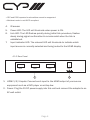
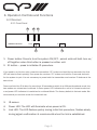
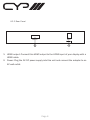
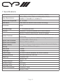
CWHDI-TxRx
HDMI Wireless Transmitter &
Receiver Set
OPERATION MANUAL
Precautions
Failure to follow the precautions described below may cause damage to this HDMI
device and void the warranty.
• DO NOT open the case. This will void the warranty, if you find a problem with
this product, please return it to your retailer or seller who will assist you or
provide you with a solution.
• DO NOT use third-Party AC adaptors or power cords. This may damage the
device.
• DO NOT bump, jar or drop the product because it may cause damage and void
the warranty.
• DO NOT allow liquids to come into contact with the units because they may
cause damage.
Table of Contents
1.
Introduction
1
2.
Features
1
3.
Package Contents
2
4.
Operation Controls and Functions
3
4.1
4.2
Transmitter
3
4.1.1. Front Panel
3
4.1.2. Rear Panel
4
Receiver
5
4.2.1. Front Panel
5
4.2.2. Rear Panel
6
5.
Remote Control
7
6.
Connection Diagram
8
7.
Specifications
9
8.
Troubleshooting
10
Finden Sie ab Seite 9.
1. Introduction
This wireless HDMI transmitter and receiver set uses baseband technology with
a Wireless High Definition Interface (WHDI) to deliver uncompressed HD video
and audio up to 15~30 metres open field, while maintaining superb,
wire-equivalent quality and robustness with no latency. The transmitter and
receiver both come with embedded antennas.
2. Features
•Uncompressed wireless transmission of HD video/ audio at an equivalent
quality to using a cable connection.
•Supports common video resolutions including;
•HDTV: 480i/p, 576i/p, 720p, 1080i and 1080p(24fps/30fps)
•PC: VGA@60/72, SVGA@60/72, XGA@60/70.
•Transmission distance between 15~30 metres open field depending on
environment, no line of sight required.
•Real time link, less than 1 millisecond latency
•Strong 256-bit AES based encryption for security.
•Video Data Rates 1.5Gbps.
•5GHz licensed band, MIMO RF.
•Supports CEC functionality.
•Fully HDCP Compliant.
•Unicast and Multicast broadcast options.
•Auto shut down of both devices when one of them is switched off.
•Control Channel allows two-way communications at 10Kbps.
Page 1
3. Package Contents
• Wireless HDMI Transmitter unit.
• Wireless HDMI Receiver unit.
• 2 x 5V/2.6A DC power supply adaptors.
• Operation Manual.
• CR-67 Transmitter Remote
• CR-68 Receiver Remote
• Device Stand x 2
Page 2
4. Operation Controls and Functions
4.1 Transmitter
4.1.1 Front Panel
4
5
6
PowerL ink
CWHDI-TX Transmitter
Power
7
HDMI1 HDMI2 HDMI3
Input
1
ID
2
3
1. Power button: Press to turn the system ON/OFF - paired units will both turn on/
off together when this button is pressed on either unit.
2. Input button: Press to select input source (1/2/3).
3. ID button: Press to initialise ID reset procedure and re-link units if necessary*
*These sets are already paired before they leave the factory so it is usually not necessary for you to
reset them again unless the units have been unpaired.
If you need to re-link the units, press the transmitter “ID” button and hold for two seconds (the Link
LED will start to flash quickly), then press the receiver “ID” button and hold for two seconds and wait
for the system to pair. It is not necessary to press both the transmitter and receiver ID buttons at the
same time.
Press and hold the ID button for more than 10 seconds to switch to a different broadcast mode, the
two modes are unicast and multicast. Unicast mode means that the transmitter transmits to only one
paired receiver. In multicast mode, the transmitter transmits to multiple receivers. A Green power LED
indicates the unit is in Unicast mode and a red power LED indicates it is switched to multicast Mode.
The factory default is Unicast mode. We recommend that you use this mode for household use.
Note: Due to the nature of the transmission, the multicast mode has no uplink and therefore no
bi-directional communication between the Transmitter and Receiver. This results in the following
limitations:
• HDCP protected content can not be transmitted.
Page 3
• CEC and EDID repeater functionalities cannot be supported.
• Multicast mode is not HDCP compliant.
4.
5.
6.
7.
IR sensor.
Power LED: The LED will illuminate when power is ON.
Link LED: The LED flashes quickly during initial link procedure, flashes slowly during signal confirmation & remains solid when the link is established.
Input indicator LED: The relevant LED will illuminate to indicate which input source is currently selected and being routed to the HDMI display.
4.1.2 Rear Panel
HDMI3
HDMI2
HDMI1
1
DC 5V
2
1. HDMI 1/2/3 Inputs: Connect each input to the HDMI output of your source
equipment such as a DVD player or set-top-box.
2. Power: Plug the 5V DC power supply into this unit and connect the adaptor to an
AC wall outlet.
Page 4
4. Operation Controls and Functions
4.2 Receiver
4.2.1 Front Panel
3
IR
CWHDI-RX Receiver
4
5
Power Link
Power
ID
1
2
1. Power button: Press to turn the system ON/OFF - paired units will both turn on/
off together when this button is pressed on either unit.
2. ID button – press to initialise ID procedure.
If you need to re-link the units, press the transmitter “ID” button and hold for two seconds (the Link
LED will start to flash quickly), then press the receiver “ID” button and hold for 2 seconds and wait
for the system to pair. It is not necessary to press both the transmitter and receiver ID buttons at the
same time.
Press and hold the ID button for more than 10 seconds to switch to a different broadcast mode, the
two modes are unicast and multicast. A Green power LED indicates the unit is in Unicast mode and
a red power LED indicates it is switched to multicast Mode. The factory default is Unicast mode. We
recommend you use this mode for household use.
3.
IR sensor.
4.
Power LED: The LED will illuminate when power is ON.
5.
Link LED: The LED flashes quickly during initial link procedure, flashes slowly during signal confirmation & remains solid when the link is established.
Page 5
4.2.2 Rear Panel
HDMI OUT
DC 5V
1
2
1. HDMI output: Connect this HDMI output to the HDMI input of your display with a
HDMI cable.
2. Power: Plug the 5V DC power supply into this unit and connect the adaptor to an
AC wall outlet.
Page 6
5. Remote Control
1. Power: Press to turn the device ON/
OFF.
POWER
ID
INPUT
2. ID: Press transmitter remote’s “ID”
1
button for 2 seconds and then
2
receiver remote’s “ID” for 2 seconds
3
①
②
③
and wait for the system to pair. These
systems are already paired before
Transmitter CR-67
they leave the factory so it is not
usually necessary for you to have to
re-link the units.
POWER
ID
3. (transmitter remote only) Input
source selection: Press 1, 2 or 3 to
select your desired input source. You
can use this remote at the receiver
end to select a different input.
Receiver
Page 7
CR-68
①
②
6. Connection Diagram
Page 8
7. Specifications
Radio Power
Transmit power is configurable up to 63mW (+18dBm)
Video Resolutuions
480i/p, 576i/p, 720p, 1080i and 1080p(24fps/30fps),
VGA@60/72, SVGA@60/72, XGA@60/70
Frequencies Supported
Modulation
4.9 ~ 5.9 GHz
Bandwidth
20MHz
Wireless Range
Antenna
15 ~ 30 metres open field
System Features
Digital Video Interface
Digital Audio Interface
System Latency
Security
Input ports
Output port
Power Supply
Dimensions (mm)
Weight (g)
OFDM MIMO with WHDITH video-modem Technology
Transmitter: 4 transmit antennas and 1 recieve antenna
Receiver: 5 receiver antennas and 1 transmit antenna
Automatic Transmission Power Control (ATPC) for best power
performance.
Automatic Frequency Selection (AFS) for avoiding interference.
Up to 24bit RGB or YCbCr (4:4:4)
PCM 2ch, DTS 5.1, AC3 5.1
Less than 1 millisecond delay between video/audio source & display
Strong 256 bit AES-Based Encryption
3 x HDMI
1 x HDMI
5V/2.6A DC (US/EU standards, CE/FCC/UL certified)
162.6 (W) x 164.5 (D) x 33.5 (H)
Transmitter: 348
Receiver: 316
Chassis Material
Silk Skin Colour
Operating Temp.
Power Consumption
Plastic
Piano Black
0°C ~ 40°C
Transmitter: 1.95W
Receiver: 1.62W
Page 9
8. Troubleshooting
Situation
Check Point/s
Power LED does not illuminate when power is
ON.
1. Check the right adaptor is being used - 5V/2.6 A is
the correct adaptor.
2. Check all power connectors are plugged in correctly.
3. Press the power buttons to turn on the devices
After powering up Tx & Rx, the Link LEDs are
flashing quickly / slowly without displaying a
picture.
1. Ensure your connected screen is On, and has the
correct HDMI input selected, otherwise the Receiver
unit’s link LED will flash.
2. This is normal if the devices are pairing or learning,
the LED will flash slowly when it is carrying out a signal
confirmation. Once signal lock is confirmed the LED will
remain on.
3. If the LED flashes quickly for more than
3 minutes, perform an ID reset as described on page 3
of this manual.
4. If the LED flashes slowly for more than
3 minutes, check the input selection on the transmitter
and confirm a device is connected to that input.
The Link LED remains on but no image is displayed or an unexpected image is displayed.
1. Check if source’s resolution is supported, the device
can support up to 1080i and 1080p 24/30, please
make sure the source is sending a supported resolution, and confirm that your display can also accept that
resolution.
2. Check that both the source and the display are HDCP
compliant.
3. Check that the TV is on the correct AV channel.
4. Check all hdmi cables have a good physical connection to the Rx/Tx units and connected sources and
display.
Input LEDs do not illuminate.
If the display connected to the receiver unit is not
turned on and set to the correct HDMI channel, the
input LEDs will not illuminate.
Different colours on Power LED.
A Red Power LED indicates multicast mode
and a Green Power LED indicates Unicast mode.
If the Tx’s power LED is green but the Rx’s is Red. Press
and hold the Rx’s ID key for 10 seconds to change to
Unicast mode. In similar scenarios hold the ID button
down on the appropriate unit to set it to the required
broadcast mode. To change both units from one broadcast mode to the other carry out the procedure on both.
Page 10
www.cypeurope.com