1
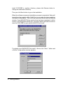
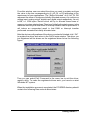
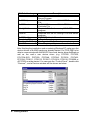
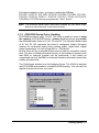
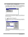
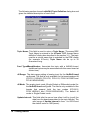
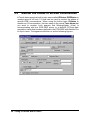
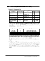
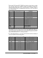
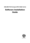
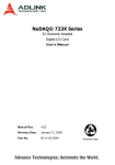
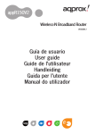
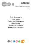
PCIS-DDE
DDE Server for
NuDAQ PCI-bus Cards (Win-NT)
User’s Guide
@Copyright 1998~1999 ADLink Technology Co., Ltd.
All Rights Reserved.
Manual Ver. 1.22: November 29, 1999
The information in this document is subject to change without prior notice in
order to improve reliability, design and function and does not represent a
commitment on the part of the manufacturer.
In no event will the manufacturer be liable for direct, indirect, special,
incidental, or consequential damages arising out of the use or inability to
use the product or documentation, even if advised of the possibility of such
damages.
This document contains proprietary information protected by copyright. All
rights are reserved. No part of this manual may be reproduced by any
mechanical, electronic, or other means in any form without prior written
permission of the manufacturer.
Trademarks
IBM PC is a registered trademark of International Business Machines
Corporation. Intel is a registered trademark of Intel Corporation. Other
product names mentioned herein are used for identification purposes only
and may be trademarks and/or registered trademarks of their respective
companies.
Getting service from ADLink
♦
Customer Satisfaction is always the most important thing for ADLink
Tech Inc. If you need any help or service, please contact us and get it.
ADLink Technology Inc.
Web Site
Sales & Service
Technical
Support
TEL
Address
♦
http://www.adlink.com.tw
[email protected]
NuDAQ
[email protected]
NuDAM
[email protected]
NuIPC
[email protected]
NuPRO
[email protected]
Software
[email protected]
AMB
[email protected]
+886-2-82265877
FAX
+886-2-82265717
9F, No. 166, Jian Yi Road, Chungho City, Taipei, 235 Taiwan, R.O.C.
Please inform or FAX us of your detailed information for a prompt,
satisfactory and constant service.
Detailed Company Information
Company/Organization
Contact Person
E-mail Address
Address
Country
TEL
Web Sit
FAX
Questions
Product Model
Environment to Use
Challenge Description
Suggestions for ADLink
OS
Computer Brand
M/B :
CPU :
Chipset :
Bios :
Video Card :
Network Interface Card :
Other :
Contents
CHAPTER 1 Introduction to PCIS-DDE ................ 1
1.1
W HAT IS DDE......................................................................... 1
1.2
DDE CONVERSATION .............................................................. 3
CHAPTER 2 Getting Started ................................. 5
2.1
PCIS-DDE INSTALLATION ........................................................ 5
2.1.1
2.1.2
2.2
Installation............................................................................................ 5
PCIS-DDE Device Driver Handling................................................. 9
PCIS-DDE SERVER CONFIGURATION ...................................... 11
2.2.1
/Configure/Board Configuration................................................... 11
2.2.2
2.2.3
/Configure/Topic Definition ...........................................................13
/Configure/DDE Server Settings...................................................15
CHAPTER 3 Using PCIS-DDE with InTouch ....... 17
3.1
DDE ITEM NAMES D EFINITION IN INTOUCH................................ 17
3.2
MONITOR THE C OMMUNICATION STATUS OF MODULES ................ 23
3.3
MONITOR THE STATUS OF AN DDE CONVERSATION .................... 24
CHAPTER 4 DDE Item Names In PCIS-DDE....... 27
4.1
PCI-7200/7432.................................................................... 28
4.2
PCI-7230 ............................................................................ 29
4.3
PCI-7234 ............................................................................ 30
4.4
PCI-7250(WITH/WITHOUT PCI-7251) ....................................... 31
4.5
PCI-7248/7296.................................................................... 32
4.6
PCI-7433 ............................................................................ 34
Contents • i
4.7
PCI-7434 ............................................................................ 35
4.8
PCI-9111DG/HR.................................................................. 36
4.9
PCI-9112 ............................................................................ 38
4.10 PCI-9113 ............................................................................ 40
4.11 PCI-911 4DG/HG ................................................................. 41
4.12 PCI-9118DG/HG/HR............................................................ 42
4.13 PCI-6208V/18V/08A............................................................ 44
4.14 CPCI-7252 .......................................................................... 45
Appendix InTouch Sample Programs.................. 47
I.
EXECUTE SAMPLE PROGRAMS................................................ 48
II.
CONVERTING RAW DATA OF ANALOG INPUT AND ANALOG OUTPUT TO
ENGINEERING U NIT................................................................ 50
ii • Contents
1
Introduction to PCIS-DDE
PCIS-DDE is an application for Windows NT operating systems. It acts as a
DDE (Dynamic Data Exchange) Server and allows other Windows
application programs to access data from NuDAQ PCI-bus data acquisition
cards. It may be used with Wonderware InTouch and any Microsoft
Windows program that is capable of acting as a DDE Client.
1.1
What is DDE?
DDE (Dynamic Data Exchange) is a communication protocol designed by
Microsoft to allow concurrently running programs in the Windows
environment to exchange data and instructions with each other. It
implements a client-server relationship between the applications. The
server application provides the data and accepts requests from any other
application interested in the data. The requesting applications are called
clients which can both read and write data maintained by the server. Some
applications such as InTouch and Microsoft Excel can simultaneously be
both a client and a server.
Introduction to PCIS-DDE • 1
Client applications can use DDE for one-time data transfers or for
continuous data exchanges in which updates are sent as soon as new
information is available. For one-time data transfers, the client application
only requests the “snapshot” data from the server application. For
example, as a macro for report generation is executed in Excel, a link to
another DDE program will be set up to request the specified data. The link
will be terminated after the requested data is received. Then the received
data are used to generate reports.
The continuous data exchanges mode is also named “hot link”. While a
client application sets up a link to another DDE program, it requests the
server application to advise the client whenever a specific item's value
changes. These data links will remain active until either the client or server
program terminates the link or the conversation. It is a very efficient means
of exchanging data because once the link has been established no
communication occurs until the specified data value changes. InTouch
uses DDE to communicate with I/O device drivers and other DDE
application programs.
For InTouch, if the tagname are defined as I/O type, they can read or write
their values to or from another DDE compliant Windows program. For
example, InTouch can read or write their values to Excel, and Excel can
also read or write data to InTouch Database. Whenever the data from
source are updated, the remote data are updated automatically as soon as
new information is available. DDE can be used to dispatch control
instructions to process-connected instruments. With this ability, two or
more related applications can be combined together to make up a large
size of super application. For example, Excel spreadsheet can perform the
optimal calculation for production. Thus, Excel may read data from InTouch
database, which are accessed from I/O controllers or sensors. Reference
to the data, the Excel spreadsheet performs some complicated calculation.
InTouch reads the calculated result back from Excel and then uses this
optimal value to control various production parameters.
2 • Introduction to PCIS-DDE
1.2
DDE Conversation
Two Windows application wishing to exchange data must establish a
conversation. The client opens a channel to the server application by
specifying:
l Server Application Name
For PCIS-DDE server, the application name is PciDDE.
l Topic (Logical Device) Name
The DDE topic is a general classification of data within which multiple data
items may be "discussed" (exchanged) during the conversation. For PCISDDE server, the topic might be a NuDAQ board name with its card number,
e.g. Pci7200#0. The topic is active whenever at least one conversation has
been established between the server’s logical device and the outside
world’s applications (client). The topic is de-active when the last
conversation to a topic has terminated.
l Items/Tagnames
Items are individual pieces of data that are passed between applications.
An item is active whenever any DDE conversation is referencing this item.
All the valid item names for PCIS-DDE server are mentioned in chapter 4 of
this manual. For example, the item name is “PDI” for client application (e.g.
InTouch) to get the digital input data of PCI-7200.Please refer to the related
chapter for the details.
The following statement is the DDE address convention for representing an
DDE conversation:
Application|Topic!Item
For example, to get the digital input data of PCI-7200 through PCIS-DDE
server, the conversation might be the following (assume the topic name is
defined as Pci7200#0):
PciDDE|Pci7200#0!PDI
Introduction to PCIS-DDE • 3
2
Getting Started
2.1
PCIS-DDE Installation
2.1.1 Installation
The Setup program in ADLink CD-ROM performs all tasks necessary for
complete installation.
step 1. Insert the ADLink CD-ROM into your CD-ROM drive.
step 2. If Windows NT is loaded, click the Start button on the Taskbar,
and then choose Run.
Step 3. Type x:\setup (x identifies the drive that contains the compact
disc) in Open text box, then click OK.
Step 4. Setup first displays the main screen. Select Software Package.
Step 5. Setup then displays the ADLink’s software products screen.
Select InTouch & DDE Server. Then select PCI BASE DDE to
setup PCIS-DDE.
Setup first displays a Welcome dialog box. Please click
installation.
to go on
Setup then prompts a user information dialog box including Name,
Company and Serial Number text field. The “Serial Number” field must be
filled in correctly, otherwise the PCIS-DDE will run in 120 minutes DEMO
mode.
Setup then prompts a dialog box for you to specify the destination directory
for PCIS-DDE. The default path is C:\ADLink\PCISDDE. If you want to
Getting Started • 5
install PCIS-DDE in another directory, please click Browse button to
change the destination directory.
Then you click Next button to go on the installation.
When the software component installation process is completed, Setup will
launch the driver registry utility, PciUtil, for you to make the driver registries
and board configuration. The PciUtil main window is shown as the following
window. If any NuDAQ PCI-bus card’s driver has been registered, it will be
shown on the Registered Driver list. The driver registry procedure must be
done for PCIS-DDE to work with NuDAQ PCI-bus card.
To register one of NuDAQ PCI-bus cards’ drivers, click “New…” button and
a Driver Configuration window appears.
6 • Getting Started
From this window, user can select the driver you want to register and type
the value in the box corresponding to AI, AO, DI, or DO according to the
requirement of your applications. The “Buffer Allocated” of AI, AO, DI, DO
represent the sizes of contiguous Initially Allocated memory for continuous
analog input, analog output, digital input, digital output respectively. Its unit
is KB, i.e. 1024 bytes. Device driver will try to allocate these sizes of
memory at system startup time. The size of initially allocated memory is the
maximum memory size that DMA or Interrupt transfer can be performed. It
will induce an unexpected result in that DMA or Interrupt transfer
performed exceeds the initially allocated size.
After the device configurations of the driver you select is finished, click “OK”
to register the driver and return to the PciUtil main window. The driver you
just registered will be shown on the registered driver list as the following
figure:
Then you can select Exit! Command in the menu bar to exit the driver
registry utility. To make the registered drivers work, you have to re-start
Windows NT system.
When the installation process is completed, the PCISDDE directory should
contain the following files and sub-directories.
Getting Started • 7
File/Sub-directory
PciDDE.exe
PciDDE.hlp
PciDDE.cnt
Wwdlg32.dll
Pdde.dll
PciDDE.pdf
Samples <DIR>
Samples\NuDAQ.cfg
Util <DIR>
Description
NuDAQ PCI-base card 32-bit DDE
Server Program
NuDAQ PCI-base card 32-bit DDE Server Help
File
NuDAQ PCI-base card 32-bit DDE Server Help
Contents File
Required DLL file for running PCIS-DDE server
program
Required DLL file for running PCIS-DDE server
program
PCIS-DDE User’s Manual
InTouch Sample programs
Configuration file for running sample programs
Driver Registry utility
After finishing the installation and re-entering Windows NT, make sure the
device drivers of NuDAQ cards are already started. For PCIS-DDE to be
able to communicate with NuDAQ PCI-bus card, device driver AdlDask as
well as the card’s own device driver (e.g. PCI7200, PCI7230,
PCI-7234.SYS, PCI7250, PCI7248, PCI7296, PCI7432, PCI7433,
PCI7434, PCI9111, PCI9112, PCI9113, PCI-9114, PCI9118, PCI6208 or
cPCI7252) must be started. You can open the “Control Panel”, double-click
“Devices”, and a Devices window will be shown as below.
8 • Getting Started
If the device status is none, you have to select the AdlDask,
PCI7200, PCI7230, PCI-7234, PCI7250, PCI7248, PCI7296, PCI7432,
PCI7433, PCI7434, PCI9111, PCI9112, PCI-9113, PCI-9114, PCI9118,
PCI6208 or PCI7252 device and press the “Start” button.
Note: The AdlDask driver must have been started as you press Start
button to start the card’s own device driver.
2.1.2 PCIS-DDE Device Driver Handling
PCIS-DDE provides a utility, PciUtil. This utility is used for users to make
the registry of PCIS-DDE drivers, remove installed drivers and modify
the allocated buffer sizes of AI, AO, DI and DO. The allocated buffer sizes
of AI, AO, DI, DO represent the sizes of contiguous Initially Allocated
memory for continuous analog input, analog output, digital input, digital
output respectively. Its unit is page KB, i.e. 1024 bytes.
Device driver will try to allocate these sizes of memory at system startup
time. The size of initially allocated memory is the maximum memory size
that DMA or Interrupt transfer can be performed. It will induce an
unexpected result in that DMA or Interrupt transfer performed exceeds the
initially allocated size.
The PciUtil main window is as the following figure. The PciUtil is installed
with PCIS-DDE and located in <InstallDir>\Util directory. You can use it to
register the device drivers you need.
Getting Started • 9
Using this utility to install a new driver, please refer to section 2.1.1.
Using PciUtil to change the buffer allocated settings of one of the
NuDAQ PCI-bus cards’ device drivers, select the driver from the
Registered Driver list and click “Modify…” button and then a “Driver
Configuration” window is shown as below.
Inside the allocated buffer size fields of AI, AO, DI and DO are the originally
set values. Type the value in the box corresponding to AI, AO, DI, or DO
according to the requirement of your applications, and then click “OK”
button.
To remove a registered driver, select the driver from the Registered Driver
list in The PciUtil main window and click “Remove” button. The selected
driver will be deleted from the registry table.
10 • Getting Started
2.2
PCIS-DDE Server Configuration
For PCIS-DDE to perform properly, PCIS-DDE server configuration is
required before its operation. To perform the required configurations, start
up PCIS-DDE by clicking PCIS-DDE V1.2 from program files menu and
then the PCIS-DDE Server main window is s hown as follows:
The configuration items include Board Configuration, Topic Definition and
DDE Server Settings. The detail of the configuration items is described in
the following sections.
2.2.1 /Configure/Board Configuration
To configure the board, select Board Configuration from Configuration
Menu in NuDAQ main window. The "Adapter Board Settings" dialog box is
as follows:
The fields and buttons in Adapter Board Settings dialog box are described
in the following:
Getting Started • 11
Push this button to close the dialog box.
Define a new board and the “NuDAQ Adapter Card Setting”
dialog box displays as the figure below.
This button appears only as at least one board has been
defined. Push this button to modify the settings for the
selected board.
This button appears only as at least one board is defined. Push
this button to delete the selected board.
The following section shows the NuDAQ Adapter Card Setting dialog box
and gives the detailed description of each field:
Board Type:Select the board type for this configuration.
Board Number:Select the board sequence number. The board sequence
number represents the sequence number of the cards
with the same card type or card series plugged in the PCI
slots (The relationship between card types and card
series is listed in the description of Board Type field). The
card sequence number setting is according to the PCI slot
sequence in the mainboard. For example, if there are two
PCI-7200 cards and one PCI-9112 card plugged on your
PC, the Board number of the PCI-7200 board in the prior
slot should be set as 0, and the Board number of the other
PCI-7200 will be 1. The Board number of the PCI-9112
card has to be set as 0.
12 • Getting Started
Reply Timeout:This field is used to input the amount of time (in seconds)
the NuDAQ boards on the system will be given to reply to
commands from the PCIS-DDE Server. The Timeout
message is sent out when a NuDAQ board fails to
respond. The value is valid from 1 to 32 and the default
value is 3 seconds.
2.2.2 /Configure/Topic Definition
To define the Topics, select Topic Definition from Configuration Menu in
NuDAQ main window. The topic definition operation is not valid until at
least one board is defined. The "Topic Definition" dialog box is as follows:
The fields and buttons in Topic Definition dialog box are described in the
following:
Push this button to close the dialog box.
Define a new topic and the NuDAQ Topic Definition dialog
box displays as the figure below.
This button appears only as at least one topic is defined. Push
this button to modify the settings for the selected topic.
This button appears only as at least one topic is defined. Push
this button to delete the selected topic.
Getting Started • 13
The following section shows the NuDAQ Topic Definition dialog box and
gives the detailed description of each field:
Topic Name: This field is used to enter a Topic Name. (The same DDE
Topic Name is entered in the InTouch "DDE Access Name
definition" dialog box described in the section 3.1). The topic
must be a unique name that is matched by the DDE clients
(for example InTouch). Topic Name can be up to 32
characters long.
Card Type#BoardNumber: Associate the topic with a NuDAQ board
(additional topics may be associated with this same board at
a later time).
AI Range: The data range setting of analog input for the NuDAQ board
configured. The field is only available for the boards support AI
(PCI-9111 DG/HR, PCI-9112, PCI-9113, PCI9114 DG/HG and
PCI-9118DG/HG/HR).
AI Mode: The analog input mode (Single Ended or Differential mode) for
the NuDAQ board configured. The field is only available for the
boards that support both the two modes (PCI-9112,
PCI9114DG/HG and PCI-9118DG/HG/HR). The default AI
mode is Single Ended mode.
Update Interval: This field tells the server how often it will try to poll the
data from the board associated to the topic defined. The
valid range of Update Interval is from 1 to 65535 and
the default value is 1000(msec).
14 • Getting Started
Since each DI/O port of PCI-7248/96 can be set as input port or output
port, this button is used to configure the port direction (Input port or output
port) of PCI-7248/7296 boards. To perform PCI-7248/96 DI/O port
configuration, push this button and the dialog box is shown as the
following figure:
In this window, you can set each port as an input port or an output port by
selecting the port direction from the combo box that is beside each port
name. CN1 and CN2 sections are available for both PCI-7248 and
PCI-7296. However, CN3 and CN4 sections are only available for
PCI-7296.
2.2.3 /Configure/DDE Server Settings
A number of parameters that controls the internal operation of the Server
can be set. In most cases, the default settings for these parameters provide
good performance and do not require changing. However, they can be
changed to fine-tune the Server for a specific environment. To configure
the PCIS-DDE server, select DDE Server Settings from Configuration
Menu in NuDAQ main window. The "DDE Server Settings " dialog box is as
follows:
Getting Started • 15
The fields and buttons in dialog box above are described in the following:
Configuration File Directory: This field is used to specify the path (disk
drive and directory) in which the PCIS-DDE will save its
configuration file. PCIS-DDE will use this path to load the
configuration file the next time it is started.
Note: Only the "path" may be modified with this field. The configuration file
is always named NuDAQ.cfg.
Protocol Timer Tick: This field is used to change the frequency, where the
Server executes the communication protocol. The
valid range of the Protocol Timer Tick is from 1 to
65535 and the default value is 50 msec.
NetDDE being used: This field must be checked when Wonderware
NetDDE is used.
Push this button to close "DDE Server Settings" dialog box
and cancel this command.
Push this button to save the settings and close "DDE Server
Settings" dialog box after the configuration is finished.
16 • Getting Started
3
Using PCIS-DDE with InTouch
3.1
DDE Item Names Definition in InTouch
For InTouch, the DDE item name can be defined in Tag Name Dictionary to
read/write data from other applications. To define the tagnames, invoke the
/Special/Tag Name Dictionary... command (in WindowMaker). The "
Tagname Dictionary " dialog box will appear:
Click on this button to define a new Tag Name
Using PCIS-DDE With InTouch • 17
Enter the Tagname in this field. (The tagname defined here
is the name InTouch will use. The PCIS-DDE server does
not see this name. The item name that PCIS-DDE server
uses is defined in Item Name field, an input field in Details
box).
Click on this button to select the tag type. The Tag Types
dialog box is as follows:
To access PCIS-DDE server items, the type of Tagname should be I/O
type.
There are four I/O types. They are briefly described in the following:
l I/O Discrete
Discrete input/output tagname with a value of either 0 (False, Off)
or 1 (True, On).
l I/O Integer
A 32-bit signed integer value between -2,147,483,648 and
2,147,483,647.
l I/O Real
Floating (decimal) point tagname. The floating point value may be
38
38
between -3.4e and +3.4e . All floating point calculations are
performed with 64-bit resolution, but the result is stored in 32-bit.
l I/O Message
Text string input/output tagname that can be up to 131 characters
long.
18 • Using PCIS-DDE With InTouch
After selecting tag types, the "Details" dialog box associated to the tag
type will appear:
Note: If Details dialog box does not appear, click Details at the top of the
Tagname Dictionary dialog box.
Input all the information related to the tag name. If selecting I/O Integer or
I/O Real as the type for your tagname, it is required to input the values of
Min EU, Max EU, Min Raw and Max Raw
Click on this button to define the DDE access
name associated to the tagname. The Access Name dialog box is as
follows:
Using PCIS-DDE With InTouch • 19
Click on this button to close the dialog box.
Click on this button to define a new DDE access name.
Click on this button to modified the selected DDE access
name. An Modify Access Name dialog box will appear.
Click on this button to delete the selected DDE access nam e.
The following figure illustrate the Add/Modify Access Name dialog box:
Enter an arbitrary name. InTouch uses Access
Names to reference real-time I/O data of tagname
associated to the Access name. (It is generally
advisable that the same name defined for the
PCIS-DDE topic is used here.)
If the data resides in a network I/O Server, type the remote
node's name in the field.
20 • Using PCIS-DDE With InTouch
In this field, type the actual program name, PciDDE, for
the PCIS-DDE server program from which the data
value will be acquired.
Note: Do not enter the .exe extension portion of the program name.
In this field, type the topic name you want to access. The
"Topic Name" MUST be the same name used when the
topics were configured in the PCIS I/O DDE Server
program.
Select Advise all items if you want the server program to poll for all
data whether or not it is in visible windows, alarmed, logged, trended or
used in a script.
Note: Selecting this option will impact performance, therefore its use is not
recommended.
Select Advise only active items if you want the server program to poll only
points in visible windows and points that are alarmed, logged, trended or
used in any script.
Click on this button to save the settings followed by closing the
dialog box and then the Access Names dialog box will
reappear. Click “Done” to close the dialog box and return to
Tagname Dictionary dialog box and Details dialog box as the
figure below.
Click on this button to cancel the command followed by
closing the dialog box and then the Access Names dialog box
will reappear. Click “Done” to close the dialog box and return
to Tagname Dictionary dialog box and Details dialog box as
the figure below.
Using PCIS-DDE With InTouch • 21
The last step is to define the DDE item name. In this field, type the item
name for the desired data value in the PCIS-DDE server. Please refer to
the chapter 4 for the valid item names of each NuDAQ PCI-bus data
acquisition cards. For example, to access the digital input value of
PCI-7200 module, type PDI in this field.
Note: It is important to understand that the "tagname" is the name used
within InTouch to refer to a data value. The Item is the name used by
I/O DDE Server program to refer to the same value. These names
do not have to be the same, however, it is recommended when
applicable to use the same names.
22 • Using PCIS-DDE With InTouch
3.2
Monitor the Communication Status of
Modules
For each board being used, there is a built-in discrete item, Status, that
you can use to monitor the state of the communications with NuDAQ
PCI-bus data acquisition cards. Status is set to "0" when communications
with the device fails and set to "1" when communications is successful.
From InTouch, you can read the state of the communications by defining a
tagname and associating it with the topic configured for the device by using
the word Status as the item name. The following figure is an example of
Tagname Definition for monitoring the status of all communication to a
NuDAQ PCI-bus data acquisition card in InTouch.
From Excel, you can read the status of the communications by entering
the following formula in a cell:
=PciDDE|TopicName!'STATUS'
Using PCIS-DDE With InTouch • 23
3.3
Monitor the Status of an DDE Conversation
InTouch also supports a built-in topic name called IOStatus (DDEStatus in
versions prior to InTouch 7.0) that can be used to monitor the status of
specific DDE conversations. When using the built-in topic IOStatus to
monitor an I/O conversation, the item name is the actual Topic Name that
you want to monitor. Let's assume that WindowViewer (View) is
communicating with the PCIS-DDE server to a NuDAQ PCI-bus data
acquisition cards that has been defined in the PCIS-DDE with Module1 for
its topic name. The tagname definition is as the following figures:
24 • Using PCIS-DDE With InTouch
Excel can also be used to perform this same type of monitoring by entering
the same information in a formula in a spreadsheet cell. For example, to
monitor the same topic as above, the following would be entered:
=View|IOStatus!'Module1'
Using PCIS-DDE With InTouch • 25
4
DDE Item Names In PCIS-DDE
The following sections list the commands and the corresponding item
names and the data types of NuDAQ PCI-bus data acquisition cards. The
Special Command Set is available for all the NuDAQ PCI-bus data
acquisition cards. Except special commands, all the item names begin
with an “P” character. The definition of each data type is described in
section 3.1 of this manual. Please refer to the related section for the
details.
DDE Item Names In PCIS-DDE • 27
4.1
PCI-7200/7432
Digital I/O Command Set
Command
Item Name
Digital Data In in digital
format
PDI*
Digital Data Out in
digital format
PDO*
Digital Data In in real
format
PRDI
Digital Data Out in
String mode
PSDO
Requested/Poked
value
Data: xxxxxxxxxx
Example: 1234567890
Range: -2147483648~
2147483647
Data: xxxxxxxxxx
Example: 1234567890
Range: -2147483648~
2147483647
Data:xxxxxxxxxx
Example: 1234567890
Range: 0 ~
4294967295
Data: xxxxxxxxxx
Example: 1234567890
Range: 0 ~
4294967295
Nth bit Digital Data In
PBI0…PBI31 Data: 0 or 1
(N is the bit number)
Fast Nth bit Digital Data PASBI0 …
Data: 0 or 1
In (N is the bit number) PASBI31*
R/W Data Type
R
Integer
W
Integer
R
Real
W
String
R
Integer
R
Integer
* For InTouch, the value of Nth bit of PDO/PDI can be poked/advised by
using Tag.0N as the item name. For example, to poke the value of the 0th
bit of PDO, set tagname as Tag.00, or to poke the value of the 1st bit of
PDO, set tagname as Tag.01.
* To get the value of Nth bit of PDO/PDI by using Tag.0N as the item name,
the data type of PDO/PDI have to be set as integer. As mentioned before,
the “integer” is “32-bit signed i nteger” in InTouch. That means the range of
“integer” is –2147483648 ~ 2147483647. However, to poke or advise the
32-bit unsigned data, use “PRDI” (the data type is real) for digital input or
“PSDO” (the data type is string) for digital output.
28 • DDE Item Names In PCIS-DDE
* “PASBIn” and “PBIn” (n is the bit number) commands are both used for
n-th bit digital data in. For signal bit digital data input, the performance of
these two commands are almost the same. However, for multi-bits digital
data input, using “PASBIn” can get much higher performance than “PBIn”.
Hence “PASBIn” command is especially suitable for multi-bits digital data
input.
4.2
PCI-7230
Digital I/O Command Set
Command
Item Name
Requested/Poked
value
Data Range: 0 ~ 65535
Example: 32767
Data Range: 0 ~ 65535
Example: 32767
R/W
Data
Type
R
Integer
W
Integer
Digital Data In
PDI
Digital Data Out
PDO
Nth bit Digital Dat In
(N is the bitnumber)
Fast Nth bit Digital
Data In (N is the bit
number)
PBI0…
PBI15
Data: 0 or 1
R
Integer
PASBI0 …
PASBI15*
Data: 0 or 1
R
Integer
* For InTouch, the value of Nth bit of PDO/PDI can be poked by using
Tag.0N as the item name. For example, to poke the value of the 0th bit of
PDO, set tagname as Tag.00, or to poke the value of the 1st bit of PDO,
set tagname as Tag.01.
* “PASBIn” and “PBIn” (n is the bit number) commands are both used for
n-th bit digital data in. For signal bit digital data input, the performance of
these two commands are almost the same. However, for multi-bits digital
data input, using “PASBIn” can get much higher performance than “PBIn”.
Hence “PASBIn” command is especially suitable for multi-bits digital data
input.
DDE Item Names In PCIS-DDE • 29
4.3
PCI-7234
Digital I/O Command Set
Command
Item Name
Digital Data Out
in digital format
PDO*
Digital Data Out
in String mode
PSDO*
Requested/Poked
value
Data: xxxxxxxxxx
Example: 1234567890
Range: -2147483648 ~
2147483647
Data: xxxxxxxxxx
Example: 1234567890
Range: 0 ~ 4294967295
R/W Data Type
W
Integer
W
String
* For InTouch, the value of N th bit of PDO can be poked/ by using Tag.0N
as the item name. For example, to poke the value of the 0 th bit of PDO,
set tagname as Tag.00, or to poke the value of the 1s t bit of PDO, set
tagname as Tag.01.
* To get the value of N th bit of PDO by using Tag.0N as the item name, the
data type of PDO have to be set as integer. As mentioned before, the
“integer” is “32-bit signed integer” in InTouch. That means the range of
“integer” is –2147483648 ~ 2147483647. However, to poke 32-bit
unsigned data, use “PSDO” (the data type is string) for digital output.
30 • DDE Item Names In PCIS-DDE
4.4
PCI-7250(with/without PCI-7251)
Digital I/O Command Set
Command
Item Name
Digital Data In
PDI0…PDI3*
Digital Data Out
PDO0…PDO3*
Nth bit Digital Data In
PBI0…PBI31*
(N is the bit number)
Fast Nth bit Digital
PASBI0 …
Data In (N is the bit
PASBI31*
number)
Requested/Poked
R/W Data Type
value
Data Range: 0 ~ 255
Example: 128
Data Range:0 ~ 255
Example: 128
R
Integer
W
Integer
Data: 0 or 1
R
Integer
Data: 0 or 1
R
Integer
* The PCI-7551 cards are used as the expansion boards of the PCI-7250
board. Please refer to the PCI-7250/7251 user’s manual for the details. In
PCIS-DDE, the digital I/O ports and their related item names of
PCI-7250/7251 are defined as follows:
Card
Port
Item Name
PCI-7250
PCI-7251#1
PCI-7251#2
PCI-7251#3
0
1
2
3
PDO0 / PDI0 / PBI0 ~ PBI7
PDO1 / PDI1 / PBI8 ~ PBI15
PDO2 / PDI2 / PBI16 ~ PBI23
PDO3 / PDI3 / PBI24 ~ PBI31
* For InTouch, the value of N th bit of PDOn/PDIn (n is the port number) can
be poked/advised by using Tag.0N (N is the bit number) as the item name.
For example, to poke the value of the 0th bit of PDO0, set tagname as
Tag.00, or to poke the value of the 1s t bit of PDO0, set tagname as
Tag.01.
* “PASBIn” and “PBIn” (n is the bit number) commands are both used for
n-th bit digital data in. For signal bit digital data input, the performance of
these two commands are almost the same. However, for multi-bits digital
data input, using “PASBIn” can get much higher performance than “PBIn”.
Hence “PASBIn” command is especially suitable for multi-bits digital data
input.
DDE Item Names In PCIS-DDE • 31
4.5
PCI-7248/7296
Configuration and Digital I/O Command Set
Command
Item Name
Configuration
PCP*
Setting
Requested/Poked
value
Data: xxxx
Example: 000F,
indicates that
Output ports:
P1A, P1B,P1CH, P1CL
Input ports:
P2A, P2B, P2CH, P2CL
P3A, P3B, P3CH, P3CL
P4A, P4B, P4CH, P4CL
PDI1A, PDI1B, PDI1C,
Data Range: 0 ~ 15 for
PDI1CH, PDI1CL,
PDI1CH, PDI1CL,
P DI2A, PDI2B, PDI2C,
PDI2CH, PDI2CL,
PDI2CH, PDI2CL,
Digital Data In
PDI3CH, PDI3CL,
P DI3A, PDI3B, PDI3C,
PDI41CH, PDI4CL;
PDI3CH, PDI3CL,
Data Range: 0 ~ 255 for
PDI4A, PDI4B, PDI4C,
the other ports.
PDI4CH, PDI4CL
PDO1A, PDO1B,
PDO1C, PDO1CH,
PDO1CL,
Data Range: 0 ~ 15 for
PDO2A, PDO2B,
PDI1CH, PDI1CL,
PDO2C, PDO2CH,
PDI2CH, PDI2CL,
Digital Data
PDO2CL,
PDI3CH, PDI3CL,
Out
PDO3A, PDO3B,
PDI41CH, PDI4CL;
PDO3C, PDO3CH,
Data Range: 0 ~ 255 for
PDO3CL,
the other ports
PDO4A, PDO4B,
PDO4C, PDO4CH,
PDO4CL
Nth bit Digital
Data In (N is
Data: 0 or 1
PBI0…PBI95*
the bit
number)
Fast Nth bit
Digital Data In PASBI0…
Data: 0 or 1
(N is the bit
PASBI95*
number)
32 • DDE Item Names In PCIS-DDE
R/W Data Type
W
Message
R
Integer
W
Integer
R
Integer
R
Integer
* Since each DI/O port of PCI-7248/96 can be set as input port or output
port, the item name PCP is used to configure the direction of each port.
One bit of the poked data of PCP controls one port. The port names of
PCI-7248/7296 and their corresponding control bits in PCP are listed in
the following table:
Port Name Controlled Bit in PCP
P1A
P1B
P1CU
P1CL
P2A
P2B
P2CU
P2CL
P3A
P3B
P3CU
P3CL
P4A
P4B
P4CU
P4CL
0
1
2
3
4
5
6
7
8
9
10
11
12
13
14
15
Remarks
For both PCI-7248/7296
For both PCI-7248/7296
For both PCI-7248/7296
For both PCI-7248/7296
For both PCI-7248/7296
For both PCI-7248/7296
For both PCI-7248/7296
For both PCI-7248/7296
For PCI-7296 only
For PCI-7296 only
For PCI-7296 only
For PCI-7296 only
For PCI-7296 only
For PCI-7296 only
For PCI-7296 only
For PCI-7296 only
* For example, if P1A, P1B, P1CH, P1CL are set as output ports and P2A,
P2B, P2CH, P2CL P3A, P3B, P3CH, P3CL, P4A, P4B, P4CH, P4CL are
set as input ports, the poked value in hexadecimal format will be 000F,
that is 0000 0000 0000 1111 (in binary format).
* For “Nth bit Digital Data In” command, the bit number and their related port
name are listed in the following table:
Port Name Valid bit number in PBI
P1A
P1B
P1C
P2A
P2B
P2C
P3A
P3B
P3C
P4A
P4B
P4C
0~7
8 ~15
16 ~ 23
24 ~ 31
32 ~ 39
40 ~ 47
48 ~ 55
56 ~ 63
64 ~ 71
72 ~ 79
80 ~ 87
88 ~ 95
Remarks
For both PCI-7248/7296
For both PCI-7248/7296
For both PCI-7248/7296
For both PCI-7248/7296
For both PCI-7248/7296
For both PCI-7248/7296
For PCI-7296 only
For PCI-7296 only
For PCI-7296 only
For PCI-7296 only
For PCI-7296 only
For PCI-7296 only
DDE Item Names In PCIS-DDE • 33
* “PASBIn” and “PBIn” (n is the bit number) commands are both used for
n-th bit digital data in. For signal bit digital data input, the performance of
these two commands are almost the same. However, for multi-bits digital
data input, using “PASBIn” can get much higher performance than “PBIn”.
Hence “PASBIn” command is especially suitable for multi-bits digital data
input.
4.6
PCI-7433
Digital I/O Command Set
Command
Item Name
Requested/Poked
value
Data: xxxxxxxxxx
Example: 1234567890
PDI0 ~ PDI1*
Range: -2147483648~
2147483647
Data: xxxxxxxxxx
Digital Data In in real PRDI0~
Example: 1234567890
format
PRDI1
Range: 0 ~ 4294967295
Nth bit Digital Data In PBI0 …
Data: 0 or 1
(N is the bit number) PBI63
Fast Nth bit Digital
PASBI0 …
Data In (N is the bit
Data: 0 or 1
PASBI63*
number)
Digital Data In in
digital format
R/W Data Type
R
Integer
R
Real
R
Integer
R
Integer
* There are 64 digital input channels in a PCI-7433 card. Please refer to the
PCI-7433 user’s manual for the details. In PCIS-DDE server, the digital
input ports and their related item names of PCI-7433 are defined as
follows:
Channel Number
0 ~ 31
32 ~ 63
Port
Item Name
0
1
PDI0 / PRDI0
PDI1 / PRDI1
* For InTouch, the value of Nth bit of PDI0/PDI1 can be advised by using
Tag.0N as the item name. For example, to advice the value of the 0 th bit
of PDI0, set tagname as Tag.00, or to poke the value of the 1s t bit of PDI0,
set tagname as Tag.01.
34 • DDE Item Names In PCIS-DDE
* To get the value of N th bit of PDI0/PDI1 by using Tag.0N as the item name,
the data type of PDI0/PDI1 have to be set as integer. As mentioned
before, the “integer” is “32-bit signed integer” in InTouch. That means the
range of “integer” is –2147483648 ~ 2147483647. However, to poke or
advise the 32-bit unsigned data, use “PRDI0” or “PRDI1” (the data type is
real) for digital input.
* “PASBIn” and “PBIn” (n is the bit number) commands are both used for
n-th bit digital data in. For signal bit digital data input, the performance of
these two commands is almost the same. However, for multi-bits digital
data input, using “PASBIn” can get much higher performance than “PBIn”.
Hence “PASBIn” command is especially suitable for multi-bits digital data
input.
4.7
PCI-7434
Digital I/O Command Set
Command
Item Name
Digital Data Out
PDO0 ~ PDO1*
in digital format
Digital Data Out PSDO0 ~
in String mode PSDO1*
Requested/Poked
value
Data: xxxxxxxxxx
Example: 1234567890
2147483648 ~
2147483647
Data: xxxxxxxxxx
Example: 1234567890
Range: 0 ~ 4294967295
R/W Data Type
W
Integer
W
String
* There are 64 digital output channels in a PCI-7434 card. Please refer to
the PCI-7434 user’s manual for the details. In PCIS-DDE server, the
digital input ports and their related item names of PCI-7434 are defined as
follows:
Channel Number
Port
Item Name
0 ~ 31
32 ~ 63
0
1
PDO0 / PSDO0
PDO1 / PSDO1
* For InTouch, the value of N th bit of PDO0/PDO1 can be poked/ by using
Tag.0N as the item name. For example, to poke the value of the 0th bit of
PDO0, set tagname as Tag.00, or to poke the value of the 1s t bit of PDO0,
set tagname as Tag.01.
DDE Item Names In PCIS-DDE • 35
* To get the value of Nth bit of PDO0/PDO1 by using Tag.0N as the item
name, the data type of PDO0/PDO1 have to be set as integer. As
mentioned before, the “integer” is “32-bit signed integer” in InTouch. That
means the range of “integer” is–2147483648 ~ 2147483647. However, to
poke 32-bit unsigned data, use “PSDO0” or “PSDO1” (the data type is
string) for digital output.
4.8
PCI-9111DG/HR
Analog I/O, Digital I/O and Range Setting Command Set
Command
Item Name
Read Analog Input
PAI0…PAI15
Fast Analog Input
PASAI0 …
PASAI15*
Analog Data Out
PAO0
Digital Data In
PDI
Digital Data Out
PDO
Nth bit Digital Data In
(N is the bit number) PBI0…PBI15
Fast Nth bit Digital
PASBI0 …
Data In (N is the bit
PASBI15*
number)
36 • DDE Item Names In PCIS-DDE
Requested Poked
value
For PCI-9111DG:
Data range:
-2048 ~ 2047
example: 1024
For PCI-9111HR:
Data Range:
-32768 ~ 32767
example: 12345
For PCI-9111DG:
Data range:
-2048 ~ 2047
example: 1024
For PCI-9111HR:
Data Range:
-32768 ~ 32767
example: 12345
Data range:
0 ~ 4095
example: 2048
R/W Data Type
R
Integer
R
Integer
W
Integer
R
Integer
W
Integer
Data: 0 or 1
R
Integer
Data: 0 or 1
R
Integer
Data Range: 0~65535
Example: 32767
Data Range: 0~65535
Example: 32767
Analog Input Range
Setting
PSR
Digital Data In from
Extended input port
PEDI
Digital Data Out to
Extended output port
Nth bit Digital Data In
from Extended output
channels (N is the bit
number)
Fast Nth bit Digital
Data In from
Extended output
channels (N is the bit
number)
PEDO
Data Range*: 1 ~ 5
Example: 2, indicates
that the AI range is ±5V
Data Range: 0~255
Example: 127
Data Range: 0~15
Example: 12
W
Integer
R
Integer
W
Integer
PEBI0…PEBI
15
Data: 0 or 1
R
Integer
PAEBI0 …
PAEBI15*
Data: 0 or 1
R
Integer
Data Range*: 1 ~ 3
Example: 2, indicates
that the EDO port is set
as output port
W
Integer
Extended output port
PSEDO
Setting
* In PCIS-DDE, each analog input range is represented by an integer. The
valid input ranges and their corresponding integers for PCI-9111DG/HR
are:
Analog Input Range
Represented Integer
±10V
±5V
±2.5V
±1.25V
±0.625V
1
2
3
4
5
* In PCIS-DDE, the valid extended output port (EDO) settings for
PCI-9111DG/HR are:
EDO mode
Represented Integer
EDO_INPUT
EDO_OUT_EDO
EDO_OUT_CHN
1
2
3
DDE Item Names In PCIS-DDE • 37
* “PASAIn” and “PAIn” (n is the channel number) commands are both used
for analog data in. For signal channel analog data input, the performance
of these two commands are almost the same. However, for
multi-channels analog data input, using “PASAIn” can get much higher
performance than “PAIn”. Hence “PASAIn” command is especially
suitable for multi -channels a nalog data input.
* “PASBIn/PAEBIn” and “PBIn/PEBIn” (n is the bit number) commands are
both used for n-th bit digital data in. For signal bit digital data input, the
performance of these two commands are almost the same. However, for
multi-bits digital data input, using “PASBIn/PAEBIn” can get much higher
performance than “PBIn/PEBIn”. Hence “PASBIn/PAEBIn” command is
especially suitable for multi -bits digital data input.
4.9
PCI-9112
Analog I/O, Digital I/O and Range Setting Command Set
Command
Item Name
Read Analog Input
PAI0…PAI15
Fast Analog Input
PASAI0 …
PASAI15*
Analog Data Out
PAO0
PAO1
Digital Data In
PDI
Digital Data Out
PDO
Nth bit Digital Data In
PBI0…PBI15
(N is the bit number)
Fast Nth bit Digital
PASBI0 …
Data In (N is the bit
PASBI15*
number)
Analog Input Range
PSR
Setting
38 • DDE Item Names In PCIS-DDE
Requested/Poked
value
Data range:
0 ~ 4095
example: 2048
Data range:
0 ~ 4095
example: 2048
Data range:
0 ~ 4095
example: 2048
R/W Data Type
R
Integer
R
Integer
W
Integer
R
Integer
W
Integer
Data: 0 or 1
R
Integer
Data: 0 or 1
R
Integer
Data Range*:
1 ~ 5 (Bipolar)
15 ~ 18 (Unipolar)
Example: 2, indicates
that the AI range is ±5V
W
Integer
Data Range: 0~65535
Example: 32767
Data Range: 0~65535
Example: 32767
* In PCIS-DDE, each analog input range is represented by an integer. The
valid input ranges and their corresponding integers for PCI-9112 are:
Analog Input Range
Represented Integer
±10V
±5V
±2.5V
±1.25V
±0.625V
0 ~ 10V
0 ~ 5V
0 ~ 2.5V
0 ~ 1.25V
1
2
3
4
5
15
16
17
18
* “PASAIn” and “PAIn” (n is the channel number) commands are both used
for analog data in. For signal channel analog data input, the performance
of these two commands are almost the same. However, for
multi-channels analog data input, using “PASAIn” can get much higher
performance than “PAIn”. Hence “PASAIn” command is especially
suitable for multi -channels analog data input.
* “PASBIn” and “PBIn” (n is the bit number) commands are both used for
n-th bit digital data in. For signal bit digital data input, the performance of
these two commands are almost the same. However, for multi-bits digital
data input, using “PASBIn” can get much higher performance than “PBIn”.
Hence “PASBIn” command is especially suitable for multi-bits digital data
input.
DDE Item Names In PCIS-DDE • 39
4.10 PCI-9113
Analog Input and Range Setting Command Set
Command
Item Name
Read Analog
PAI0…PAI31
Input
Fast Analog
Input
PASAI0 …
PASAI31*
Analog Input
PSR
Range Setting
Requested/Poked value
Data range:
0 ~ 4095
example: 2048
Data range:
0 ~ 4095
example: 2048
Data Range*:
1, 2, 7 ~ 12 (Bipolar)
15, 19 ~ 21 (Unipolar)
Example: 2, indicates that the
AI range is ±5V
R/W Data Type
R
Integer
R
Integer
W
Integer
* The analog input signal polarity and full range of PCI9113 have to be set
by using the jumpers (JP1 and JP2) on board. Please refer to the
PCI-9113 user’s manual for the details.
* In PCIS-DDE, each analog input range is represented by an integer. The
valid input ranges and their corresponding integers for PCI-9113 are:
Analog Input Range
Represented Integer
±10V
±5V
±0.5V
±0.05V
±0.005V
±1V
±0.1V
±0.01V
0 ~ 10V
0 ~ 1V
0 ~ 0.1V
0 ~ 0.01V
1
2
7
8
9
10
11
12
15
19
20
21
* “PASAIn” and “PAIn” (n is the channel number) commands are both used
for analog data in. For signal channel analog data input, the performance
of these two commands are almost the same. However, for
multi-channels analog data input, using “PASAIn” can get much higher
40 • DDE Item Names In PCIS-DDE
performance than “PAIn”. Hence “PASAIn” command is especially
suitable for multi -channels analog data input.
4.11 PCI-9114DG/HG
Analog Input, Digital I/O and Range Setting Command Set
Command
Item Name
Read Analog Input
PAI0…PAI31
Fast Analog Input
PASAI0 …
PASAI31*
Digital Data In
PDI
Digital Data Out
PDO
Nth bit Digital Data In
PBI0…PBI15
(N is the bit number)
Fast Nth bit Digital
PASBI0 …
Data In (N is the bit
PASBI15*
number)
Analog Input Range
Setting
PSR
Requested/Poked
value
Data range:
-32768 ~ 32767
example: 1024
Data range:
-32768 ~ 32767
example: 1024
R/W Data Type
R
Integer
R
Integer
R
Integer
W
Integer
Data: 0 or 1
R
Integer
Data: 0 or 1
R
Integer
For PCI-9114DG
Data Range*: 1 ~ 4
For PCI-9114HG
W
Data Range*: 1, 10, 11, 12,
Example: 2, indicates that
the AI range is ±5V
Integer
Data Range: 0~65535
Example: 32767
Data Range: 0~65535
Example: 32767
* In PCIS-DDE, each analog input range is represented by an integer. The
valid input ranges and their corresponding integers for PCI-9114DG/HG
are:
Analog Input Range
Represented Integer
±10V
±5V
±2.5V
±1.25V
±1V
±0.1V
±0.01V
1
2
3
4
10
11
12
DDE Item Names In PCIS-DDE • 41
* “PASAIn” and “PAIn” (n is the channel number) commands are both used
for analog data in. For signal channel analog data input, the performance
of these two commands are almost the same. However, for
multi-channels analog data input, using “PASAIn” can get much higher
performance than “PAIn”. Hence “PASAIn” command is especially
suitable for multi -channels analog data input.
* “PASBIn” and “PBIn” (n is the bit number) commands are both used for
n-th bit digital data in. For signal bit digital data input, the performance of
these two commands is almost the same. However, for multi-bits digital
data input, using “PASBIn” can get much higher performance than “PBIn”.
Hence “PASBIn” command is especially suitable for multi-bits digital data
input.
4.12 PCI-9118DG/HG/HR
Analog I/O, Digital I/O and Range Setting Command Set
Command
Item Name
Resd Analog Input
PAI0…PAI15
Fast Analog Input
PASAI0…
PASAI15
Analog Data Out
PAO0
PAO1
Digital Data In
PDI
Digital Data Out
PDO
42 • DDE Item Names In PCIS-DDE
Requested/Poked
value
For PCI-9118DG/HG
Data range
0 ~ 4095
example: 2048
For PCI-9118HR
Data Range
-32768 ~ 32768
example: -12345
For PCI-9118DG/HG
Data range:
0 ~ 4095
example: 2048
For PCI-9118HR
Data Range:
-32768 ~ 32768
example: -12345
Data range:
0 ~ 4095
example: 2048
Data Range: 0 ~ 15
Example: 15
Data Range: 0 ~ 15
Example: 15
R/W Data Type
R
Integer
R
Integer
W
Integer
R
Integer
W
Integer
Nth bit Digital Data
In (N is the bit
PBI0…PBI15
number)
Fast Nth bit Digital
PASBI0…
Data in (N is the bit
PASBI3
number)
Analog Input Range
PSR
Setting
Data: 0 or 1
R
Integer
Data: 0 or 1
R
Integer
For PCI-9118DG/HR
Data Range*:
2 ~ 5 (Bipolar)
15 ~ 18 (Unipolar)
For PCI-9118HG
Data Range*:
2, 7 ~ 9 (Bipolar)
15, 19 ~ 21 (Unipolar)
Example: 2, indicates that
the AI range is ±5V
W
Integer
* In PCIS-DDE, each analog input range is represented by an integer. The
valid input ranges and their corresponding integer are:
Analog Input Range
Represented Integer
±5V
±2.5V
±1.25V
±0.625V
±0.5V
±0.05V
±0.005V
0 ~ 10V
0 ~ 5V
0 ~ 2.5V
0 ~ 1.25V
0 ~ 1V
0 ~ 0.1V
0 ~ 0.01V
2
3
4
5
7
8
9
15
16
17
18
19
20
21
* “PASAIn” and “PAIn” (n is the channel number) commands are both used
for analog data in. For signal channel analog data input, the performance
of these two commands are almost the same. However, for
multi-channels analog data input, using “PASAIn” can get much higher
performance than “PAIn”. Hence “PASAIn” command is especially
suitable for multi -channels analog data input.
DDE Item Names In PCIS-DDE • 43
* “PASBIn” and “PBIn” (n is the bit number) commands are both used for
n-th bit digital data in. For signal bit digital data input, the performance of
these two commands is almost the same. However, for multi-bits digital
data input, using “PASBIn” can get much higher performance than “PBIn”.
Hence “PASBIn” command is especially suitable for multi-bits digital data
input.
4.13 PCI-6208V/18V/08A
Configuration and Analog Output Command Set
Command
Item Name
Requested/Poked
R/W Data Type
value
Data range: 0 ~ 2,
Where
0: 0 ~ 20 mA
1: 5 ~ 25 mA
2: 4 ~ 20 mA
For PCI-6208V/16V:
Data range:
For PCI-6208V
-32768 ~ 32767
/08A:
example: 2048
PAO0 ~ PAO7
For PCI-6208A:
For PCI-6216V:
Data range:
PAO0 ~ PAO15
0 ~ 32767
example: 2048
Voltage to Current
Mode Setting for
PCP
PCI-6208A
W
Integer
Analog Data Out
W
Integer
R
Integer
W
Integer
Data: 0 or 1
R
Integer
Data:0 or 1
R
Integer
Digital Data In
PDI
Digital Data Out
PDO
Nth bit Digital Data
In (N is the bit
PBI0…PBI3
number
Fast Nth bit Digital
PASBI0…
Data In (N is the bit
PASBI3
number)
Data Range: 0 ~ 15
Example: 10
Data Range: 0 ~ 15
Example: 10
* “PASBIn” and “PBIn” (n is the bit number) commands are both used for
n-th bit digital data in. For signal bit digital data input, the performance of
these two commands is almost the same. However, for multi-bits digital
data input, using “PASBIn” can get much higher performance than “PBIn”.
Hence “PASBIn” command is especially suitable for multi-bits digital data
input.
44 • DDE Item Names In PCIS-DDE
4.14 cPCI-7252
Digital I/O Command Set
Command
Item Name
Digital Data In
PDI
Digital Data Out
PDO
Nth bit Digital Data In
(N is the bit number) PBI0…PBI15
Fast Nth bit Digital
PASBI0…
Data In (N is the bit
PASBI15
number)
Requested/Poked
R/W Data Type
value
Data Range: 0 ~ 65535
Example: 128
Data Range: 0 ~ 255
Example: 128
R
Integer
W
Integer
Data: 0 or 1
R
Integer
Data: 0 or 1
R
Integer
* For InTouch, the value of Nth bit of PDO/PDI can be poked/advised by
using Tag.0N (N is the bit number) as the item name. For example, to
poke the value of the 0th bit of PDO, set tagname as Tag.00, or to poke
the value of the 1st bit of PDO, set tagname as Tag.01.
* “PASBIn” and “PBIn” (n is the bit number) commands are both used for
n-th bit digital data in. For signal bit digital data input, the performance of
these two commands is almost the same. However, for multi-bits digital
data input, using “PASBIn” can get much higher performance than “PBIn”.
Hence “PASBIn” command is especially suitable for multi-bits digital data
input.
DDE Item Names In PCIS-DDE • 45
Appendix InTouch Sample
Programs
There are several InTouch sample programs provided in this software
package. They could help you to program your own applications by using
InTouch and PCIS-DDE easily. The brief descriptions of these sample
programs are specified as follows:
7200Demo
7248Demo
7296Demo
7230Demo
7234Demo
7250Demo
7432Demo
7433Demo
7434Demo
6208_16Vdemo
6208Ademo
PCI-7200 InTouch Sample Program -32-bit DI & 32-bit DO
PCI -7248 InTouch Sample Program -24-bit DI & 24-bit DO
Output ports:
P1A, P1B, P1CH, P1CL
Input ports:
P2A, P2B, P2CH, P2CL
PCI –7296 InTouch Sample Program -48-bit DI & 48-bit DO
Output ports:
P1A, P1B, P1CH, P1CL
P3A, P3B, P3CH, P3CL
Input ports:
P2A, P2B, P2CH, P2CL
P4A, P4B, P4CH, P4CL
PCI –7230 InTouch Sample Program -16-bit DI & 16-bit DO
PCI –7234 InTouch Sample Program -32-bit DO
PCI -7250 InTouch Sample Program -4 ports 8-bit DI/ Relay DO
PCI -7432 InTouch Sample Program -32-bit DI/DO
PCI -7433 InTouch Sample Program -64-bit DI
PCI -7434 InTouch Sample Program -64-bit DO
PCI -6208V/16V InTouch Sample Program -8 channels AO
PCI -6208A InTouch Sample Program --
Intouch Sample Programs • 47
9111Demo
9112Demo
9113Demo
9114dgDemo
9118dghgDemo
7252Demo
I.
0 to 20 mA of 8 channels AO
PCI –9111DG InTouch Sample Program 16 bit DI/DO, 16 channels AI, 1 channel AO
PCI -9112 InTouch Sample Program –
16 bit DI/DO, 16 channels AI, 2 channel AO
PCI -9113 InTouch Sample Program –
32 channels AI
PCI –9114DG InTouch Sample Program –
32 channels AI, 16 bit DI/DO
PCI-9118DG/HG InTouch Sample Program -16 bit DI/DO, 16 channels AI, 2 channel AO
cPCI -7252 InTouch Sample Program –
16 bit DI, 8 bit Relay DO
Execute Sample Programs
To run these sample programs, please follow the following steps:
Step1. Execute PCIS-DDE program
Step 2. Configure PCIS-DDE properly
The topic names required for each sample program have to be defined.
The demo programs with their own corresponding topics are list in the
following table:
Demo Program
Topic Name
7200Demo
PCI7200#0
7248Demo
PCI7248#0
7296Demo
PCI7296#0
7230Demo
PCI7230#0
7234Demo
PCI7234#0
7250Demo
PCI7250#0
7432Demo
PCI7432#0
7433Demo
PCI7433#0
7434Demo
PCI7434#0
6208_16VDemo
PCI6208V#0
6208ADemo
PCI6208A#0
9111Demo
PCI9111DG#0
9112Demo
PCI9112#0
9113Demo
PCI9113#0
9114dghgDemo
PCI9114DG#0
9118dghgDemo
PCI9118DG#0
7252Demo
cPCI7252#0
48 • Intouch Sample Programs
Please refer to chapter 2 for the detailed descriptions about the PCIS-DDE
Server configuration.
A configuration file “NuDAQ.cfg”, located in Samples directory, is provided.
This configuration file defines all the topic names required for executing our
sample programs. To use this configuration file, set the configuration file
path as the directory where this configuration file is located (the default is
“C:\ADLink\Pcisdde\Samples”), and then re-execute PCIS-DDE server
program.
This configuration file will be used while PCIS-DDE Server program is
re-executed. For the configured topics fitting your system, use
“/Configure/Topic Definition” command to modify the contents of the topics
(e. module address, data range, … etc.). Please refer to section 2.2.2 for
the detailed descriptions about topic definition.
Step 3. Start the InTouch program (INTOUCH.EXE) and select the InTouch
sample program you want to execute in the list in the InTouch Application
Manager dialog box. If the sample programs are not shown in the list, on
the Tools menu, click Find Applications. The Starting directory for
search dialog box appears and locates the directory in which you want to
search for applications, and then click OK. The InTouch Application
Manager will reappear displaying icons for all the applications that were
found in the selected directory.
Please refer to InTouch User’s Guide or related reference books to get the
information about using InTouch.
Intouch Sample Programs • 49
II.
Converting Raw Data of analog input and
analog output to Engineering Unit
In InTouch, you can convert raw data of AI and AO to engineering unit in
tagname dictionary dialog box. For example, the analog input range is ±
5V and the data range of AI raw data is 0 to 4095 for PCI9112. You can
set the range of engineering unit and raw data as the following figure:
Since the data conversion will be performed by InTouch, it’s very convenient
for users using engineering unit to perform AI/AO in InTouch.
50 • Intouch Sample Programs