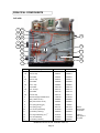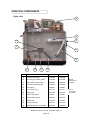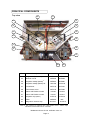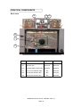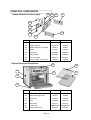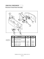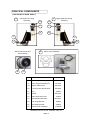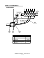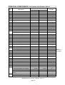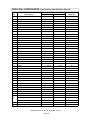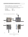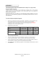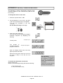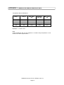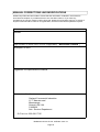
1
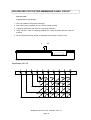
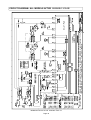
SERVICE
ALL CTM3 MODELS & TIM HORTON'S COMBINATION OVEN
MANUFACTURED FROM JANUARY 2003
SERVICE MANUAL
Mealstream
CAUTION MICROWAVE EMISSIONS
DO NOT BECOME EXPOSED TO EMISSIONS FROM THE MICROWAVE GENERATOR
OR PARTS CONDUCTING MICROWAVE ENERGY
Mealstream Ovens Pt. No. 32Z3403 Issue 15
Page 1
TABLE OF CONTENTS
Microwave safety precautions................................................. 3
Safety code ............................................................................. 4
Product specifications ............................................................. 5
Installation instructions............................................................ 6
Main features ....................................................................... 7-8
Principal components: LHS..................................................... 9
Principal components: RHS .................................................. 10
Principal components: Top.................................................... 11
Principal components: Back view.......................................... 12
Principal components: door, roof and heater element .......... 13
Principal components: Cavity Parts & External Panels......... 14
Principal components: Electronic control panel assembly .... 15
Principal components: Tim Hortons Control panels .............. 16
Principal components: ( not shown in main views ) ............. 17
Principal components: Input wiring details ............................ 18
Principal components: Part no. identification charts ........ 19-21
Procedure for Microwave leakage test............................. 22-23
Procedure for Power output measurement ........................... 24
Procedures for Principal Component tests ...................... 25-26
Procedure for Door interlock adjustment and test .......... 27-29
Procedure for building and fitting the door ....................... 30-34
Procedure for replacing door seal assembly.................... 35-36
Procedure for removing shelf runners & element cover........ 37
Procedure for replacing Heater Element............................... 38
Procedure for replacing Hot air Motor assembly................... 39
Procedure for replacing Magnetron assembly ................. 40-41
Procedure for Testing Membrane panel circuit ................ 42-43
Circuit diagrams .............................................................. 44-47
Error codes and diagnostics.................................................. 48
Appendix 1: Test Procedure for Tim Hortons........................ 49
Appendix 2: MenuKey® Download procedure ...................... 50
Appendix 3: Temperature Sensor resistance data................ 51
Manual corrections and modifications................................... 52
Mealstream Ovens Pt. No. 32Z3403 Issue 15
Page 2
MICROWAVE SAFETY
CAUTION
WARNING TO SERVICE TECHNICIANS
PRECAUTIONS TO BE OBSERVED BEFORE AND DURING
SERVICING TO AVOID POSSIBLE EXPOSURE TO
EXCESSIVE MICROWAVE ENERGY
(a)
Do not operate or allow the oven to be operated with the door open.
(b)
Make the following safety checks on all ovens to be serviced before
activating the magnetron or other microwave source , and make repairs
as necessary:
1) interlock operation.
2) proper door closing.
3) seal and sealing surfaces (arcing, wear, and other damage).
4) damage to or loosening of hinges and latches.
5) evidence of dropping or abuse.
(c)
Before turning on microwave power for any service test or inspection
within the microwave generating compartments, check the magnetron,
wave guide or transmission line, and cavity for proper alignment,
integrity and connections.
(d)
Any defective or misadjusted components in the interlock, monitor, door
seal, and microwave generation and transmission systems shall be
repaired, replaced, or adjusted by procedures described in this manual
before the oven is released to the owner.
(e)(i) A microwave leakage check to verify compliance with the Federal
Performance Standard should be performed on each oven prior to
release to the owner. For U.S.A.
(e)(ii) A microwave leakage check to verify compliance with the Canadian
Regulation, HEALTH AND WELFARE, SOR/79 920 should be
performed on each oven prior to release to the owner. For CANADA.
Mealstream Ovens Pt. No. 32Z3403 Issue 15
Page 3
SAFETY CODE
This manual is designed to assist engineers who have been on a recognised product
familiarisation and training course run by Garland. It has been prepared to offer technical
guidance for the Mealstream range of Combination Microwave Ovens.
Please remember that it is wiser not to attempt a service task if you are unsure of being able to
complete it competently, quickly, and above all safely.
To avoid injury to yourself, and to protect the appliance from possible damage, please follow this
Safety Code when servicing these ovens.
Before attempting to repair the oven, check it for microwave leakage.
Check that the oven is not emitting microwaves, even when supposedly not in
operation.
Check that the oven is not operating continuously, whether the display indicates
cooking or not.
Always discharge the HT capacitors before working on the oven using a suitably
insulated 10 MΩ Resistor.
Before removing any covers from the oven, do all of the following.
• Switch off the mains supply and remove the plug from the wall socket.
or
• If the oven is hard wired, ensure that the power is turned off at the isolator switch.
Note:
The On/Off switch on the oven is not adequate protection against electric
shock, as it does not isolate all of the internal wiring from the mains.
Upon completion of a service on a Mealstream oven, or before reconnecting the appliance to the
electrical supply for testing, check all of the following points:
•
•
•
•
•
•
•
All internal electrical connections are correct (see wiring diagram Page 44-47).
All wiring insulation is correct and is not touching a sharp edge.
All grounding connections are electrically and mechanically secure.
All door safety interlocks are secure and mechanically sound.
The door operation is smooth, and the arms run freely in the slots.
The door activates all three of the door interlock switches in the correct order
(see pages 27-29).
The temperature sensor is correctly connected to the Power PCB.
Before finishing a service call, recheck the following points:
•
•
•
•
All of the electronics are functioning correctly, and all of the touch pads are working.
Microwave emissions are below permissible limit - 4 mW/cm².
The power output of the oven is checked in accordance with page 24.
Oven has correct 2 inch ( 50mm ) air gap all round and 2 inch ( 50mm ) above.
Air flow should not be restricted. (see page 6).
Mealstream Ovens Pt. No. 32Z3403 Issue 15
Page 4
PRODUCT SPECIFICATIONS
Model Number: + Voltage + Frequency + Phases + Controls + Country
Model No.
CTM3
Voltage
Frequency
Phases
208V
20
240V
24
50Hz
50
60Hz
60
Single
1
Three
3
Control Type
Series 5
S5
Country
UK
UK
Customer Variant
N.America
A
N.America
TH = Tim Hortons
Power
Requirements
208Volts
240Volts
Power Output
Microwave 100% 1425W
Convection
3000W
Combination
1425W + 3000W
External
Dimensions
Height
30 inches ( 765mm )
Width
29.5 inches ( 770mm )
Depth
25 inches ( 635 mm)
208V ac 60Hz 30Amp 2P & G
240V ac 60Hz 40Amp 2P & G
Manufacturers Height
recommended
clearances
Width
32 inches ( 815 mm )
Depth
27 inches ( 685 mm)
Internal
Dimensions
Height
Width
Depth
Capacity
10.2 inches ( 260mm )
19.3 inches ( 490mm )
14.2 inches ( 360mm )
1.62 ft³ ( 45.86 litres )
Weight
Nett
Gross packed
198 lb.s ( 90 kg )
227 lbs ( 103 kg )
Construction
Cavity
Casework
304 Stainless Steel
Settings
Microwave
Temperature
Timer
Programs
100%,75%,50%,25%, Convection only
Off, 300°F, 350°F, 400°F, 440°F, 480°F
Up to 30 minutes per stage
Cook Programs can have 3 cooking stages of up to 30
minutes for each stage
31.5 inches ( 795 mm )
Mealstream Ovens Pt. No. 32Z3403 Issue 15
Page 5
INSTALLATION INSTRUCTIONS
Installation Instructions for Mealstream Combination Ovens
Power Supply Requirements
The Mealstream Series should be connected to a suitable electricity supply, which can cope
with the switching-on surge that occurs with certain types of catering equipment, including
microwaves. Because of this requirement, we strongly recommend that a separate, suitably
rated supply is installed for the oven.
The supply for the oven should be fitted with a Type "C" or Time Delay circuit breaker,
rated at:
50 Amp for 208V electrical supply ( 2PH + GND )
50 Amp for 240V electrical supply ( 2PH + GND ) Canada models
30 Amp for 208V electrical supply ( 2PH + GND )
30 Amp for 240V electrical supply ( 2PH + GND )
US models
If the oven is hard-wired to the supply, a double-pole isolator switch with a contact gap of at
least 1/8 inch ( 3 mm ) should be fitted.
Grounding requirement
This appliance must be connected to a grounded, metallic, permanent wiring system, or an
equipment grounding conductor should be run with the circuit conductors and connected to the
equipment grounding terminal or lead on the appliance.
Positioning the Oven
In order to maintain adequate ventilation for air intake
and exhaust, and to allow access for cleaning filters,
you must allow a minimum of 2 inches ( 50 mm )
clearance at the sides and rear of the oven,
and at least 2 inches ( 50 mm ) above.
Air intake temperature should not exceed 110°F/45°C
excessive temperature will lead to reduced operating
duty cycle, or premature ageing of internal components.
Failure to comply with these conditions will invalidate
the warranty.
NEVER
NEVER
Install an oven above fryers,
grills, griddles or any other
major heat source.
32ins
31.5ins
27ins
Stack machines on top of
each other. Always use a
double stand or a separate
shelf.
ALWAYS Place containers in the cavity
carefully - impact damage
may chip the vitreous enamel
coating on the runners and
baffle plate.
Note:
The minimum recommended
clearance required for air flow
Mealstream Ovens Pt. No. 32Z3403 Issue 15
Page 6
16ins
MAIN FEATURES
a
b
b
c
f
g
d
j
i
e
h
k
a On/Off SWITCH
f HOT AIR FAN
This is used to turn the oven On or Off.
IT DOES NOT ISOLATE INTERNAL
WIRING FROM THE MAINS SUPPLY.
b EXHAUST VENTS
Allows exhausted air from the magnetron
cooling system to escape.
c OVEN CAVITY
The oven cavity is mainly constructed
from stainless steel panels. It must be
kept clean.
d BAFFLE PLATE
Situated behind the baffle plate, and
circulates the hot air through the baffle
plate, over the heating element, and around
the edge of the baffle plate back into the
cavity.
g RATING PLATE
The rating plate is situated on the rear of
the oven, and states the Model, Serial
Number, Electrical Ratings and
Manufacturers telephone number.
h DOOR
Forms the inside rear of the oven and
covers the hot air circulation fan. This
must be cleaned on a regular basis, and
kept free of debris.
The door consists of a thermally insulated
inner section, and an additional air gap
provided by a twin skinned door front to
lower the surface temperature.
i DOOR SEAL
e RUNNERS
These are mounted on each side of the
oven cavity to support the rectangular
racks or oven trays.
j ELECTRICAL SUPPLY CORD
Electrical supply cord is situated on the rear
of the oven,
k AIR FILTER
Main intake for cooling air for internal
components. Must be clear of obstructions.
Mealstream Ovens Pt. No. 32Z3403 Issue 15
Page 7
MAIN FEATURES
Electronic control panel
a
b
j
i
h
g
f
a
Stage LED's
b
Program & Time Display
e
Convection Pad
f
Power Pads
g
Time / Preset Pads
h
Temperature Set Pads
i
Cancel / Callback Pad
j
Program Pad
N
Menukey™
Tim Hortons control panel
a
M
N
e
b
N
MENU
KEY
K
L
K
Preheat
L
Cancel
M
Icon Cook Pads
N
MenuKey™
O
Quarter, Half & Full Batch Load
M
Mealstream Ovens Pt. No. 32Z3403 Issue 15
Page 8
O
PRINCIPAL COMPONENTS
Left side
1
1A
2
2A
3
3A
4
4A
5
5A
13
6
12
14
7
11
8
10
9
No
Description
208V
240V
1
Fuse holder
30Z0231
30Z0231
1A
Fuse 10 amp
30Z0217
30Z0217
2
Fuse holder
30Z0231
30Z0231
2A
Fuse 10 amp
30Z0217
30Z0217
3
Fuse holder
30Z0285
30Z0285
3A
Fuse 1 amp
30Z0957
30Z0957
4
Fuse holder
30Z1178
30Z1178
4A
Fuse 20 amp
30Z1177
30Z1177
5
Fuse holder
30Z1178
30Z1178
5A
Fuse 20 amp
30Z1177
30Z1177
6
Electrical supply terminal block
31Z0149
31Z0149
7
Filter ( Heater circuit )
30Z0997
30Z0997
8
Filter ( Microwave circuit )
30Z0997
30Z0997
9
Door spring (short type)
520000
520000
Door spring( Long )
40C1141
40C1141
10
Door arm stop assembly
11C0279
11C0279
11
Microswitch ( Primary )
30Z0240
30Z0240
11C0167
11C0167
9
A
B
12
Door hinge assembly ( LH )
13
Door arm assembly
11C0300
11C0300
14
Microswitch ( Monitor )
30Z0240
30Z0240
Mealstream Ovens Pt. No. 32Z3403 Issue 15
Page 9
Note A
Ovens after
June 2003
Note B
See page 17
for parts
PRINCIPAL COMPONENTS
Right side
95
22
21
59
15
20
90
16
No
17
18
19
Description
208V
240V
15
Door arm assembly
11C0300
11C0300
16
Door hinge assembly ( RH )B
11C0166
11C0166
17
Micro-switch ( Secondary )
30Z0240
30Z0240
18
Door arm stop assembly
11C0279
11C0279
19
Door spring
520000
520000
19
Door spring( Long )A
40C1141
40C1141
20
Steam pipe
40C1023
40C1023
21
Steam vent guard
790061
790061
22
Temperature sensor
50E123
50E123
59
Rubber stop
31Z1150
31Z1150
90
Cavity Vent Pipe
40C1013
40C1013
95
Diode Board assy. with leads
11M0325
11M0325
Mealstream Ovens Pt. No. 32Z3403 Issue 15
Page 10
Note B
See page 17
for parts
Note A
Ovens after
June 2003
PRINCIPAL COMPONENTS
Top view
60
61
87
87
23
23
24
24
63
63
26
26
27
27
62
28
No
Description
208V
240V
23
Magnetron (Panasonic)
30Z1171
30Z1171
24
Resistor 470 R
30Z0283
30Z0283
26
Capacitor 0.88µf (2300V)A
30Z0861
30Z0861
26
Capacitor 0.88µf (2500V) Kit
10C0192
10C0192
27
Transformer
30Z1139
30Z1191
28
Twin blower motor
30Z1145
30Z1067
60
25mm OD Flexible conduit
314402
314402
61
20mm OD Flexible conduit
314401
314401
62
Capacitor clip (99mm)
31Z0176
31Z0176
63
Filter
30Z0997
N/A
87
Magnetron Thermal Trip
2571016
2571016
Note A: This Capacitor is replaced with 0.88µf 2500V and 2 x 109mm clips
included in a service kit Part No. 10C0192
Mealstream Ovens Pt. No. 32Z3403 Issue 15
Page 11
PRINCIPAL COMPONENTS
Back view
94
104 105
Description
208V
88
64
65
No
240V
64
Hot air motor assembly
11C0312
11C0312
65
Capacitor 6µF
30Z1148
30Z1148
88
Overheat Safety Thermostat
30Z1024
30Z1024
94
Hot Air motor Resistor 50R
N/A
30Z1165
104
Twin Blower Resistor 39R
N/A
30Z1164
105
Twin Blower Resistor 50R
N/A
30Z1165
Mealstream Ovens Pt. No. 32Z3403 Issue 15
Page 12
PRINCIPAL COMPONENTS
86
Door and cavity roof
67
86
72
106
107
77
108
109
71
89
76
No
Description
208V
240V
101825
101825
53
M5 Hex/hd s/s Screw
67
Stirrer glass assy. ( inc. long seals )
11C0319
11C0319
71
Door seal kit
11C0292
11C0292
72
Door choke
790007
790007
86
Cavity roof seal (short)
790052
790052
Door Assembly Garland
11C0336
11C0336
Door Assembly Tim Hortons
11C0380
11C0380
Door Assembly Unbranded
11C0418
11C0418
93
76
Door Handle Towel Rail
32Z1064
32Z1064
77
Bolt 1/4" 20 UNC 3/4" Hex
109050
109050
89
Door Handle
40C1020
40C1020
106
Flat Washer S/S M5 x 20
104036
104036
107
Nylon Washer
104250
104250
108
Spring Washer
31Z5005
31Z5005
109
Flat Washer S/S M6 x 20
104054
104054
Mealstream Ovens Pt. No. 32Z3403 Issue 15
Page 13
PRINCIPAL COMPONENTS
70
Heater Element and Cavity parts
103
69
92
57
68
102
92
70
85
No
Description
208V
240V
57
Mesh washer
31Z5044
31Z5044
68
Heater element
40C0949
40C0948
69
Heater element cover plate
790047
790047
70
Baffle
11C0311
11C0311
85
Dome Nut
80X7025
80X7025
92
Tray Support
40C0950
40C0950
102
Hot Air Impeller
MC3111
MC3111
103
Hot Air Impeller Securing Nut
105065
105065
External Parts and accessories
98
96
100
101
97
110
99
No
Description
208V
240V
96
Side Panel Left Side
790002
790002
97
Side Panel Right Side
790003
790003
98
Top Panel
790005
790005
99
Foot
32Z1052
32Z1052
100
Wire Rack
40C1011
40C1011
101
Crumb Tray
RBR290X02
RBR290X02
110
Rear Outer Panel
40C0951
40C0951
Mealstream Ovens Pt. No. 32Z3403 Issue 15
Page 14
PRINCIPAL COMPONENTS
Electronic Control Panel Assembly
29
34
33
32
31
73
No
Tim Hortons
See page 16
30
Description
208V
240V
29
On/Off Switch
30Z0503
30Z0503
30
Control Panel Assy with Menukey
(except Tim Hortons)
11C0379
11C0379
31
Logic Board (except Tim Hortons)
11C0377
11C0377
32
Relay Board (except Tim Hortons)
11C0316
11C0212
33
AC Ribbon connector
11M0116
11M0116
34
DC Ribbon connector
11M0117
11M0117
73
MenuKey Assembly
10C0148
10C0148
Mealstream Ovens Pt. No. 32Z3403 Issue 15
Page 15
TIM HORTONS CONTROL PANEL
US/ English
No
Description
208V
240V
30
Control Panel Assy with Menukey
11C0332
11C0332
31
Logic Board
11C0331
11C0331
32
Relay Board
11C0316
11C0212
208V
240V
US/ English 1/4 Load
No
Description
30
Control Panel Assy with Menukey
11C0412
11C0412
31
Logic Board
11C0411
11C0411
32
Relay Board
11C0402
11C0403
208V
240V
French Canadian
No
Description
30
Control Panel Assy with Menukey
11C0413
11C0413
31
Logic Board
11C0411
11C0411
32
Relay Board
11C0402
11C0403
208V
240V
Unbranded
No
Description
30
Control Panel Assy with Menukey
11C0414
11C0414
31
Logic Board
11C0411
11C0411
32
Relay Board
11C0402
11C0403
Mealstream Ovens Pt. No. 32Z3403 Issue 15
Page 16
PRINCIPAL COMPONENTS
( not shown in main views )
12
Left Hand Door Hinge
Assembly
16
52
52
51
51
55
56
Right Hand Door Hinge
Assembly
54
54
53
53
Motor shaft screen and
seal assembly
49
Stirrer motor assembly
58
50
No.
Description
All models
12
Door Hinge Assembly LH
11C0167
16
Door Hinge Assembly RH
11C0166
49
Motor shaft screen
40C1005
50
Hot air motor damper/seal
40C1008
51
Pin
52
Roller
53
M5 Hex/hd s/s Screw
54
M5 stainless steel Nut
55
LH Hinge bracket
790024
56
RH Hinge bracket
790025
58
Stirrer motor assembly
790027
40C0752
101825
80X7003
11C0162
Mealstream Ovens Pt. No. 32Z3403 Issue 15
Page 17
PRINCIPAL COMPONENTS
Input wiring details
6
Green/Yellow
L1
L2
Black
Green
White
48
47
46
No
Description
All models
6
Electrical Supply Terminal Block
31Z0149
46
Cable Gland
31Z0500
47
Gland Nut
31Z0499
48
Electrical Supply Cord 3 Core
30Z1162
91
Electrical Supply Plug 50Amp
(Canada)
31Z0298
Mealstream Ovens Pt. No. 32Z3403 Issue 15
Page 18
PRINCIPAL COMPONENTS: Part Number Identification Chart 1
Part No
No
Description
208V
240V
Page No
1
Fuse holder
30Z0231
30Z0231
9
1A
Fuse 10 amp
30Z0217
30Z0217
9
2
Fuse holder
30Z0231
30Z0231
9
2A
Fuse 10 amp
30Z0217
30Z0217
9
3
Fuse holder
30Z0285
30Z0285
9
3A
Fuse 1 amp
30Z0957
30Z0957
9
4
Fuse holder
30Z1178
30Z1178
9
4A
Fuse 20 amp
30Z1177
30Z1177
9
5
Fuse holder
30Z1178
30Z1178
9
5A
Fuse 20 amp
30Z1177
30Z1177
9
6
Electrical supply terminal block
31Z0149
31Z0149
9/18
7
Filter ( Heater circuit )
30Z0997
30Z0997
9
8
Filter ( Microwave circuit )
30Z0997
30Z0997
9
9
Door spring
520000
520000
9
Door spring( Long )
40C1141
40C1141
9
10
Door arm stop assembly
11C0279
11C0279
9
11
Microswitch ( Primary )
30Z0240
30Z0240
9
12
Door hinge assembly ( LH )
11C0167
11C0167
9/17
13
Door arm assembly
11C0300
11C0300
9
14
Microswitch ( Monitor )
30Z0240
30Z0240
9
15
Door arm assembly
11C0300
11C0300
10
16
Door hinge assembly ( RH )
11C0166
11C0166
10/17
17
Microswitch ( Secondary )
30Z0240
30Z0240
10
18
Door arm stop assembly
11C0279
11C0279
10
19
Door spring
520000
520000
10
Door spring( Long )
40C1141
40C1141
10
20
Steam pipe
40C1023
40C1023
10
21
Steam vent guard
790061
790061
10
22
Temperature sensor
50E123
50E123
10
23
Magnetron
30Z1171
30Z1171
11
24
Resistor 470 R
30Z0283
30Z0283
11
25
HT diode
11C0266
11C0266
11
26
Capacitor 0.88µf (2300V)
30Z0861
30Z0861
11
26
Capacitor 0.88µf (2500V) Kit
10C0192
10C0192
11
27
Transformer
30Z1139
30Z0992
11
28
Twin blower motor
30Z1145
30Z1067
11
29
On/Off Switch
30Z0503
30Z0503
15
30
Control Panel Assembly (Except Tim Hortons)
A
11C00379
11C0379
15
Control Panel Assembly US Tim Hortons
11C0412
11C0412
16
Control Panel Assy. French C. Tim Hortons
11C0413
11C0413
16
11C0414
11C0414
16
Logic Board (Except Tim Hortons)
11C0377
11C0377
15
Logic Board Tim Hortons
11C0411
11C0411
16
Control Panel Assy. UnBranded Tim
Hortons
31
Mealstream Ovens Pt. No. 32Z3403 Issue 15
Page 19
Note A
Ovens after
June 2003
PRINCIPAL COMPONENTS: Part Number Identification Chart 2
Part No
No
Description
208V
Page No
240V
46
Cable Gland
31Z0500
31Z0500
18
47
Gland Nut
31Z0499
31Z0499
18
48
Mains Cable 3 Core
30Z1162
30Z1162
18
49
Motor shaft screen
40C1005
40C1005
17
50
Hot air motor damper/seal
40C1008
40C1008
17
51
Pin
52
Roller
53
M5 Hex/hd s/s Screw
54
M5 stainless steel Nut
55
56
57
790027
790027
17
40C0752
40C0752
17
101825
101825
80X7003
80X7003
17
LH Hinge bracket
790024
790024
17
RH Hinge bracket
790025
790025
17
Mesh washer
31Z5044
31Z5044
14
58
Stirrer motor assembly
11C0162
11C0162
17
59
Rubber stop
31Z1150
31Z1150
10
60
25mm OD Flexible conduit
314402
314402
11
61
20mm OD Flexible conduit
314401
314401
11
62
Capacitor clip (99mm)
31Z0176
31Z0176
11
63
Filter
30Z0997
N/A
11
64
Hot air motor assembly
11C0312
11C0312
12
65
Capacitor (Motor starter)
30Z1148
30Z1148
12
67
Stirrer glass assy.
11C0319
11C0319
13
68
Heater element
40C0949
40C0948
14
69
Element cover plate
790047
790047
14
70
Baffle
11C0311
11C0311
14
71
Door seal kit
11C0292
11C0292
13
72
Door choke
790007
790007
13
73
Menu-Key Assembly
10C0148
10C0148
15
76
Handle
32Z1064
32Z1064
13
77
Bolt 1/4" 20 UNC 3/4" Hex
85
Dome Nut
86
13/17
109050
109050
13
80X7025
80X7025
13
Cavity roof seal (short)
790052
790052
13
87
Magnetron Thermal Trip
2571016
2571016
10
88
Cavity Overheat Thermostat
30Z1024
30Z1024
12
89
Door Handle
40C1020
40C1020
13
90
Cavity Vent Pipe
40C1013
40C1013
10
91
Electrical Supply Plug (50A Canada)
31Z0298
31Z0298
18
92
Tray Support
40C0950
40C0950
13
Door Assembly Garland
11C0336
11C0336
13
Door Assembly Tim Hortons
11C0380
11C0380
13
Door Assembly Unbranded
11C0418
11C0418
13
N/A
30Z1165
12
11M0325
11M0325
10
93
94
Hot Air motor Resistor 50R
95
Diode assy with leads
Mealstream Ovens Pt. No. 32Z3403 Issue 15
Page 20
PRINCIPAL COMPONENTS: Part Number Identification Chart 3
Part No
No
96
Description
208V
240V
Page No
Side Panel Left Side
790002
790002
14
97
Side Panel Right Side
790003
790003
14
98
Top Panel
790005
790005
14
99
Foot
32Z1052
32Z1052
14
100
Wire Shelf
40C1011
40C1011
14
101
Crumb Tray
RBR290X02
RBR290X02
14
102
Hot Air Fan
MC3111
MC3111
14
103
Hot Air Fan Securing Nut
105065
105065
14
N/A
30Z1164
12
104
Twin Blower Resistor 39R
105
Twin Blower Resistor 50R
N/A
30Z1165
12
106
Flat Washer S/S M5 x 20
104036
104036
13
107
Nylon Washer
104250
104250
13
108
Spring Washer
31Z5005
31Z5005
13
109
Flat Washer S/S M6 x 20
104054
104054
13
110
Door Spacer Kit
10C0171
10C0171
28
111
Rear Outer Panel
40C0951
40C0951
14
Mealstream Ovens Pt. No. 32Z3403 Issue 15
Page 21
PROCEDURE FOR MICROWAVE LEAKAGE TEST (1)
Warning
Check for radiation leakage after servicing. Should the leakage be more than 4mW/cm² Inform
Garland service centre immediately. After repairing or replacing any radiation safety device, keep
a written record for future reference, as required by D.H.H.S. and Health and Welfare Canada
regulation.
This requirement must be strictly observed. In addition, the leakage reading must be recorded on
the service repair documentation while in the customer’s premises.
Please Note
DO NOT attempt to carry out the following procedure
unless you have the following tools.
Tools required for microwave leakage test
Tim Hortons
600ml glass beaker
To carry out this test the Icon Pads
need to be switched to
ENGINEERING MODE PROGRAMS
See Appendix 1
Supply of cold water
Microwave leakage meter
Read and understand all of these notes and procedure before carrying out this operation.
Note before measuring.
•
Make sure that the survey meter you are using has been calibrated and is suitable for
measuring frequencies of 2,450 MHz.
•
Do not exceed meter full scale deflection, leakage meter should initially be set to the
highest scale, then adjusted down as necessary to ensure that low readings are measured
on the most sensitive range.
•
To prevent false readings, hold the probe on the grip provided and move along the areas
indicated on the following page. The probe should be moved at 1 inch/second (2.5cm).
•
With any casework removed the leakage should not exceed 4mW/cm².
•
When measuring the leakage, always hold the probe at 2” (50mm) from the test area using
the probe supplied with the instrument.
•
Always hold the probe at right angles to the oven and point of measurement.
Procedure
1
Place 275ml of cold water in the 600ml glass beaker.
2
Place the 600ml glass beaker in the centre of oven.
3
Close the door and set time for 30 seconds then press Power pad 100%
(change water every 30 seconds to prevent boiling).
Tim Hortons: In ENGINEERING MODE (see Appendix 1 ) press Pad 01 then any Load pad
(QUARTER, HALF, FULL) watch time display and open door at 30 seconds.
4
Set the leakage meter to the appropriate scale/range.
5
Move the survey meter probe along the areas indicated in (Figures 1 to 4 page 23).
6
Remember to change the water after 30 second since water that boils will result in
inaccurate readings.
Mealstream Ovens Pt. No. 32Z3403 Issue 15
Page 22
PROCEDURE FOR MICROWAVE LEAKAGE TEST (2)
•
Readings must be below 4mW/cm². If a level greater that 4mW/cm² is observed,
this should be reported to Garland Service Division immediately.
•
In any case, notes should be kept of the leakage that is observed. In terms of level and
position on the oven. This should be kept with the service documentation.
Control Panel
Door Perimeter
Rear and Side Covers
Left & right Side Air Filters.
- Figure
- Figure
- Figure
- Figure
2
2
1, 3 & 4
3&4
Test for microwave leakage at all points marked with a
Fig. 1
Fig. 2
Fig. 3
Fig. 4
Mealstream Ovens Pt. No. 32Z3403 Issue 15
Page 23
PROCEDURE FOR POWER OUTPUT MEASUREMENT
The power output specification, 1425W on this model is established under IEC 705 standard
method. This method is only workable in Laboratory controlled conditions.
An approximate method is as follows.
Tim Hortons Ovens
To carry out this test the Icon Pads need to be switched to ENGINEERING MODE PROGRAMS
See Appendix 1
1
Fill one beaker ( glass or plastic ) with one litre ( 1.78 pints ) of tap water ( at about 68ºF/
20ºC ) and measure the water temperature.
( Use a thermometer with a 1/10, 0.1 degree gauge ).
2
Place the beaker in the centre of the cavity.
3
General Market Models
Set Time to 1 minute 3 seconds and Power to 100%
Wait until the counter reaches zero.
Tim Hortons Ovens
With the oven in ENGINEERING MODE ( see Appendix 1) Press Pad 01 (Cake) and any
Load Pad ( Quarter, Half, Full ) Wait until the counter reaches zero.
4
Take the beaker out immediately stir the water with a plastic implement and measure the
water temperature.
5
Calculate the temperature rise of water in the beaker. The temperature rise of the water
should be within the following range:
Temperature Rise
27ºF ( 15ºC )
Minimum
36ºF ( 20ºC )
Maximum
Power Output is affected by the line voltage under load.
For correct Power Output measurement, the line voltage under load must be correct.
Mealstream Ovens Pt. No. 32Z3403 Issue 15
Page 24
PROCEDURES FOR PRINCIPAL COMPONENTS TEST (1)
1.
Power Transformer Test
You will need:
A Digital Multi-meter (D.M.M.)
A Megger or similar resistance meter using 500V d.c.
WARNING:
High voltages and large currents are present at the secondary winding
and filament winding of the Power Transformer. It is very dangerous to
work near this part when the oven is on. NEVER make any voltage
measurements at the High Voltage circuits, including the magnetron
filament.
WARNING:
Even when the oven is not cooking, the Power Transformer has High
Voltages present because of the Soft Start circuit. Isolate the oven
before testing.
See Safety Code ( Page 4 )
1
2
3
4
Isolate the oven from the mains supply.
Ensure that the High Voltage Capacitor is discharged before commencing work.
Remove all connections from the Power Transformer.
Using a D.M.M., check the resistance of the windings. Results should be as follows:
Mains winding (between tags)
Approximately 1.1 Ω
High Voltage winding (between tag and chassis)
Approximately 60 Ω
Filament winding (between terminals)
Less than 1 Ω
5 Using a Megger, test the insulation resistance between:
Primary winding and chassis
Pass if over 10 MΩ
Filament winding and chassis
Pass if over 10 MΩ
One end of the High Voltage winding is connected to the chassis, so this is not tested.
Mealstream Ovens Pt. No. 32Z3403 Issue 15
Page 25
PROCEDURES FOR PRINCIPAL COMPONENTS TEST (2)
2.
High Voltage Capacitor Test
You will need:
A Digital Multi-meter (D.M.M.)
A Megger or similar resistance meter using 500V d.c.
WARNING:
High voltages and large currents are present at the High Voltage Capacitor.
It is very dangerous to work near this part when the oven is on. NEVER make any voltage
measurements at the High Voltage circuits, including the magnetron filament.
WARNING:
Even when the oven is not cooking, the High Voltage Capacitor has High
Voltages present because of the Soft Start circuit. Isolate the oven before testing.
See Safety Code ( Page 4 )
1
2
3
4
Isolate the oven from the mains supply.
Ensure that the High Voltage Capacitor is discharged before commencing work.
Remove all connections from the High Voltage Capacitor.
Using a D.M.M., check for continuity between the terminals & compare results with table
Between Terminals
Pass if approximately 10 MΩ
Between Terminals and Case
Pass if open circuit
5 Using a Megger, test the insulation resistance between the terminals and the case.
Between Terminals and Case
3.
Pass if over 100 MΩ
High Voltage Rectifier Test
You will need:
A Megger or similar resistance meter using 500V d.c.
WARNING:
High voltages and large currents are present at the High Voltage Rectifier.
It is very dangerous to work near this part when the oven is on. NEVER make any voltage
measurements at the High Voltage circuits, including the magnetron filament .
WARNING:
Even when the oven is not cooking, the High Voltage Rectifier has High
Voltages present because of the Soft Start circuit. Isolate the oven before testing.
See Safety Code ( Page 4 )
1
2
3
4
Isolate the oven from the mains supply.
Ensure that the High Voltage Capacitor is discharged before commencing work.
Remove all connections from the High Voltage Rectifier.
Using the Megger, test for continuity in both directions. Compare results with following
Open Circuit both ways
FAIL
Conducts one way only
PASS
Short Circuit both ways
FAIL
Conducts one way, leaks the other
FAIL
Mealstream Ovens Pt. No. 32Z3403 Issue 15
Page 26
PROCEDURE FOR DOOR INTERLOCK ADJUSTMENT AND TEST (1)
The door on the Mealstream oven is monitored by three microswitches. These are used in the
conventional “Primary, Secondary and Monitor” switch arrangement shown below.
The switches operate as follows:
Door Interlock Arrangement
L1
Primary switch 11
Switches shown in Door Closed position
Secondary switch
17
Power Out
Power In
L2
Monitor switch 14
1. Monitor switch ( 14 ,Top left-hand Side ). The Monitor switch will produce
a short circuit across the mains supply if the Primary interlock switch is
faulty, when the door is opened, thus blowing the microwave fuse and
rendering the oven inoperative.
2. Primary Interlock ( 11 , Bottom left-hand ) and Secondary Interlock
( 17 , Bottom right-hand ) Switches. Operate simultaneously.
The Primary switch will cut off the microwave emissions from the oven when
the door is opened by breaking the electrical supply circuit to the
transformers. The Secondary interlock switch will cut off the microwave
emission if the Primary switch have failed.
Note:
If operation of the Monitor switch has caused the Microwave Fuse to blow,
the Primary and Monitor microswitches must be changed, as they may have
been damaged by the high short-circuit currents involved.
Mealstream Ovens Pt. No. 32Z3403 Issue 15
Page 27
PROCEDURE FOR DOOR INTERLOCK ADJUSTMENT AND TEST (2)
Please Note
DO NOT attempt to carry out the following procedure
unless you have the following tools and parts.
Continuity Meter
Spacer
Door Spacer Kit
Part No. 10C0171
No. required
Part No.
S10 Door Spacer 10mm
2
40C1119
S5 Door Spacer 5mm
2
40C1118
S1 Door Spacer 1mm
2
40C1114
WARNING
Before starting this test procedure please make sure that the oven is disconnected
from the electrical supply and that the oven power switch (ON/OFF) is in the OFF
position.
After each step check that the interlocks are operating in the correct order using a
continuity meter.
See Safety Code ( Page 4 )
Disconnect the microswitches and check for the continuity of the switches with a continuity meter
Step 1: Set the interlock so that they activate in the following order.
When closing the door.
Interlock
Order
SW1 (Monitor)
1st
SW2 (Primary)
2nd Note both SW2 and SW3 activate together
SW3 (Secondary)
2nd Note both SW2 and SW3 activate together
When opening the door.
Interlock
Order
SW1 (Monitor)
3rd
SW2 (Primary)
1st Note both SW2 and SW3 activate together
SW3 (Secondary)
1st Note both SW2 and SW3 activate together
Mealstream Ovens Pt. No. 32Z3403 Issue 15
Page 28
PROCEDURE FOR DOOR INTERLOCK ADJUSTMENT AND TEST (3)
Step 2: Insert S10 10mm spacer into door.
(See figure 1 below for inserting spacer
correctly).
Interlock
Step 3: Remove S10 10mm spacer and insert S1 1mm
spacer into the door and close the door.
Step 4: Remove S1 1mm spacer and insert S5 5mm
spacer into the door and close the door.
Order
SW1 (Monitor)
CLOSED
SW2 (Primary)
OPEN
SW3 (Secondary)
OPEN
Interlock
Order
SW1 (Monitor)
OPEN
SW2 (Primary)
CLOSED
SW3 (Secondary)
CLOSED
Interlock
Order
SW1 (Monitor)
OPEN
SW2 (Primary)
OPEN
SW3 (Secondary)
OPEN
If an oven fails this sequence
then check the microswitches are functioning correctly and repeat steps 1 to 4.
After carrying out this procedure make sure that the interlock monitor switch is properly connected
according to the circuit diagram on pages 44-46.
Figure 1
Door side seal
Door top seal
Door spacer
The door spacer must always be
located on the point where the side
seals and top seals meet.
Please note.
It is very important after completing this procedure to carry out a
microwave leakage test procedure. See pages 22-23.
Mealstream Ovens Pt. No. 32Z3403 Issue 15
Page 29
PROCEDURE FOR BUILDING AND FITTING MEALSTREAM DOOR
Parts required for door fitting
Please Note
DO NOT attempt to carry out the following procedure
unless you have the following tools and parts.
Item No.
Description
Part No.
Quantity
11C0166
1
101820
4
1
RHS door hinge assy
2
M5 x 10mm
3
M5 flat washer
31Z5008
29
4
M5 shake proof washer
31Z5012
29
5
Spacer
790084
2
6
M5 x 16mm hex screw
101876
2
7
Door frame assy
11C0303
1
8
LHS door hinge assy
11C0167
1
9
Door arm assy
11C0300
2
10
Door arm Pivot Pin
790010
2
11
Door spring
520000 or 40C1141
2
12
Door Stop
40C0854
2
13
Door stop spring clip
31Z5047
2
14
M5 stainless steel full nut
80X07003
23
15
Door seal set of 4
11C0292
1
16
CAF 30 Adhesive
31Z0186
As required
17
Door insulation set
40C0942
1
18
Outer Door Skin
Check Oven Model
1
19
M3 counter sunk screw
31Z3094
7
20
Choke Plate
790007
1
21
SPACER KIT
10C0171
1
Tools required for door fitting
M5 Nut runner
Door Spacers S325 & 3 off S215
Flat head screw driver
Long nose pliers
5mm open-ended spanner
Adhesive skeleton gun
Engineers rule
Mealstream Ovens Pt. No. 32Z3403 Issue 15
Page 30
PROCEDURE FOR BUILDING AND FITTING MEALSTREAM DOOR
1. Visually check all parts to be used.
2. Fit right hand side (RHS) Hinge assy. to base
assy. loosely fit in place with bottom bolts, 2
off M5 x 10mm, 2 off M5 flat washer, 2 off M5
shockproof washer.
Fit spacer to fill gap between Hinge assy and
Inner side panel, loosely fit spacer in place
with 1 off M5 bolt x 16mm, 1 off M5 flat
washer, 1 off M5 shakeproof washer.
Spacer
Hinge
fixings
3. Insert (RHS) Pivot pin of door frame into
(RHS) Hinge assy. Place door frame against
cavity face and slide on (LHS) Hinge assy to
the (LHS) Pivot pin of door frame,
Pivot
pin
4. Fit right hand side (RHS) Hinge assy to base
assy, loosely fit in place with bottom bolts, 2
off M5 x 10mm, 2 off M5 flat washer, 2 off M5
shockproof washer. Fit spacer to fill gap
between Hinge assy. and Inner side panel,
loosely fit spacer in place with 1 off M5 bolt x
16mm, 1 off M5 flat washer, 1 off M5
shakeproof washer.
Pivot pin
Mealstream Ovens Pt. No. 32Z3403 Issue 15
Page 31
PROCEDURE FOR BUILDING AND FITTING MEALSTREAM DOOR
5. Fit door frame assembly (including seals
and cage nuts) firmly against cavity and
tighten all fixing bolts to secure (RHS)
and (LHS) Hinge assy.
Hinge
6. Position door frame central by using the
following method.
Measure the distance between the side of the
door and the TDK Mounting Strip on both
sides with the door in the closed position.
Add these two measurements together and
divide by 2. Adjust hinge adjustment bolt so
the door is the distance calculated from the
TDK Mounting Strip and lock in position with
lock nut.
TDK
Mount
Door
Door hinge adjustment
7. Fit (RHS) and (LHS) door arms through slots
in cavity and insert door arm pivot pins
through door arms into door frame.
Door arm pivot pin
Spring clips
8. Fit door springs to door arms and to the hook
at base of inner side panels. Check operation
of door and remove (LHS) spring.
Mealstream Ovens Pt. No. 32Z3403 Issue 15
Page 32
PROCEDURE FOR BUILDING AND FITTING MEALSTREAM DOOR
9. Position door choke to Door Frame Assembly
making sure it is in the correct orientation (the
top of door choke is marked with ‘T‘ on the
underside).
‘T’
Mark
Stage 2
Stage 1
10. Loosely fit 3 off M5 flat washers, 3 off M5
shockproof washers, and 3 off M5 stainless
steel full nuts.
1
11. Tape choke Spacer S325 to the cavity base and
tape choke Spacers S215 to sides and top of
door choke.
Close the door and centralise the door choke.
Fit the remaining 20 M5 washers and nuts
tighten the fixings evenly.
4
3
1
Cavity base
S325
2
Choke fingers Top
S215
3
Choke fingers Left
S215
4
Choke fingers Right
S215
2
Remove spacing pieces and check door
operation.
Mealstream Ovens Pt. No. 32Z3403 Issue 15
Page 33
PROCEDURE
FOR
BUILDING
AND
FITTING MEALSTREAM DOOR
12. Fold the square piece oven insulation in half
and place it in the recess in the oven door.
Place the rectangular piece into the remainder
of the door (foil facing out).
Stage 1
13. Place the outer skin over the door frame
assembly and fix with 7 of M3x12 counter sunk
screws around the LHS, RHS and top of the
door.
Please note.
It is very important after completing this procedure,
to carry out a Door interlock adjustment and test procedure.
See pages 27-29.
Mealstream Ovens Pt. No. 32Z3403 Issue 15
Page 34
Stage 2
PROCEDURE FOR REPLACING DOOR SEAL ASSEMBLY (1)
Parts required for replacing carbon loaded door seals
Please Note
DO NOT attempt to carry out the following procedure
unless you have the following tools and parts.
Item
Description
Part Number
Quantity
1
Door seal set of 4
11C0292
1
2
CAF 30 ( Black )
31Z0186
As required
Tools required for replacing carbon loaded door seals
Long nose pliers
Adhesive skeleton gun
Flat head screw driver
Please note.
Before proceeding with this procedure ensure that the oven is disconnected
from the power supply.
If the oven has been operating recently please allow time for the oven to cool.
Removing Door seal
1
Open the oven door.
2
Use a pair of long nose pliers to unclip one end of the seal. (See figure 1 page 36)
3
Peel back the door seal assembly and unclip at the other end. (See figure 2 page 36)
4
Remove the residue CAF 30 adhesive with a flat head screw driver. (See figure 3 page 36)
5
Visually inspect the vitreous enamel to ensure that it is undamaged.
Fitting a New Seal
1
Clip on end of the door seal in place. Using a pair of long nose pliers, stretch the door seal
and connect the other end in place. (See figure 4, 5 & 6 page 36)
2
Visually inspect that the door seal is sitting in the rebate provided.
3*
Perform door interlock set-up procedure (See page 27-29)
4*
Perform a microwave leakage test procedure. (See page 22-23)
5
Lift the seal and applied a thin line of CAF 30 adhesive along the length of the rebate and
push the seal down. (See figure 7 page 36)
6
Seal the ends of the door seal with CAF 30 (See figure 8 page 36)
Leave the door in the open position to allow the adhesive to set.
* It is very important to carry out these procedures
Mealstream Ovens Pt. No. 32Z3403 Issue 15
Page 35
PROCEDURE FOR REPLACING DOOR SEAL ASSEMBLY (2)
Figure 1
Figure 2
Figure 3
Figure 4
Figure 5
Figure 6
Figure 7
Figure 8
Please note.
It is very important after completing this procedure,
to do a Door interlock adjustment and test procedure.
See pages 27-29.
Mealstream Ovens Pt. No. 32Z3403 Issue 15
Page 36
PROCEDURE FOR REMOVING SHELF RUNNERS AND ELEMENT COVER PLATE
Please Note
DO NOT attempt to carry out the following procedure
unless you have the following tools.
Tools required for removing shelf runners and element cover plate.
M6 nut runner
M5 nut runner
M5 stainless steel
dome nut
Pt. No. 80X7025
M6 x 12mm
stainless steel Hex
Head screw
Pt No. 80T7133
Element cover plate
Shelf runner
1.
Loosen the rear fixings screws of both shelf runners with M6 nut runner.
2.
Remove the front fixings screws of both shelf runners with M6 nut runner.
3.
Pull the shelf runners forwards away from the rear screws.
4.
Remove the 4 off M5 dome nut securing the Element cover plate.
5.
Lift the Element cover plate out taking care to not damage the temperature sensor pocket.
Mealstream Ovens Pt. No. 32Z3403 Issue 15
Page 37
PROCEDURE FOR REPLACING HEATER ELEMENT
Please Note
DO NOT attempt to carry out the following procedure
unless you have the following part and tools.
Parts required for replacing heater element.
Item Description
1
Heater Element
2
Mesh Washer
Part Number
Quantity
208 volt 40C0949 / 240 volt 40C0948
1
31Z5044
3
Tools required for replacing heater element.
M5 nut runner
1.
Disconnect or isolate oven from mains supply.
2.
Remove outer covers.
3.
Remove shelf runners and element cover plate
( See page 37 ).
4.
Disconnect wires from heater element terminals at rear of
oven.
5.
Remove M5 screw securing heater element.
6.
Remove heater element.
7.
Refit new heater element with new mesh
washers fitted over each terminal and 3 off
M5 Flat washer over the M5 screw (this is
very important to prevent microwave
leakage).
8.
Tighten M5 screw and check that the
heater element is not touching the
cavity or protruding to much that it
will not touch the element cover plate.
9.
Heater Element
Reconnect wires to heater element terminals
at rear of oven.
10. Replace element cover plate and shelf runners.
11. Perform Microwave Leakage procedure
(see page 22-23) checking carefully around
the heater element terminals at rear of oven.
12. Replace outer covers and fully test oven.
Mealstream Ovens Pt. No. 32Z3403 Issue 15
Page 38
M5 x 25mm Hex head
S/S screw Pt. No. 101825
3x M5 Flat
Washers
Mesh
Washers
PROCEDURE FOR REPLACING HOT AIR MOTOR ASSEMBLY
Please Note
DO NOT attempt to carry out the following procedure
unless you have the following part and tools.
Parts required for replacing hot air motor assembly.
Item Description
1
Hot Air Motor Assembly
Part Number
Quantity
11C0312
1
Tools required for replacing hot air motor assembly.
M5 nut runner
1.
Disconnect or isolate Oven from mains supply.
2.
Remove outer covers.
3.
Remove shelf runners and element cover plate (See page 37).
4.
Remove fan blade securing nut and remove fan blade.
5.
Disconnect motor connection at terminal block.
(Note: which wire colour goes to which terminal).
6.
Disconnect Motor Earth tag then undo all securing nuts from the
motor mounting plate and remove the fan motor assembly.
7.
Check the position and condition of the hot air motor damper/seal
(this a important microwave leakage seal) in the motor shaft
screen. (See page 17).
8.
Fit new hot air motor assembly, and fit all securing washers and
nuts, ensure it is aligned centrally into the hole in the cavity, and
tighten all securing nuts. Make sure the ground wire is connected.
9.
Reconnect motor connection at terminal block.
(Note: correct position of each wire colour).
Fan blade securing nut
10. Refit fan blade and fan blade securing nut, and ensure that the
fan/motor rotates free by hand.
11. Refit shelf runners and element cover plate.
12. Perform Microwave Leakage procedure (see pages 22-23),
checking carefully around the hot air motor assembly at rear
of oven.
13. Replace outer covers and fully test oven.
Mealstream Ovens Pt. No. 32Z3403 Issue 15
Page 39
Fan blade
PROCEDURE FOR REPLACING MAGNETRON ASSEMBLY (1)
Parts required for replacing magnetron
Please Note
DO NOT attempt to carry out the following procedure
unless you have the following tools and parts.
Item
Description
Part Number
Quantity
1
Magnetron
30Z1171
1
Tools required for replacing magnetron
Philips screw driver
M5 nut runner
WARNING
Before proceeding with this procedure ensure that the oven
is disconnected from the power supply,
And the high voltage capacitors are discharged
See Safety Code ( Page 4 )
1.
Remove the top and side casing from the oven.
2.
Remove the air duct cover plate.
(See figure 1 page 41)
3.
Disconnect the 2 wires and earth wire from the over temperature stat and the 3 wires from
the magnetron connection block.
(See figure 2 page 41)
4.
Remove the 4 nuts from the magnetron fixing.
(See figure 3 page 41)
5.
Remove the magnetron.
(See figure 4 page 41)
6.
Remove the 2 screws form the over temperature stat on the magnetron and remove.
(See figure 4 page 41)
7.
Visually inspect the new magnetron making sure that the wire mesh gasket seal is in place
and undamaged. Check the outer casing for any damage such as dents.
(See figure 5 page 41)
8.
Attach the oven temperature stat to the new magnetron.
(See figure 5 page 41)
9.
Visually inspect the magnetron mount in the wave guide making sure that it is undamaged
and that there is no debris that may obstruct the new magnetron when fitted.
(See figure 5 page 41)
10.
Place the new magnetron in position making sure it is in the correct orientation.
11.
Replace the 4 fixing nuts making sure that they are tightened equally.
12.
Reconnect the wiring to the over temperature stat.
13.
Reconnect the wiring to the magnetron.
14.
Replace the air duct cover.
Mealstream Ovens Pt. No. 32Z3403 Issue 15
Page 40
PROCEDURE FOR REPLACING MAGNETRON ASSEMBLY (2)
Figure 1 - 6
Figure 2
Figure 1
Magnetron
connection
block
Temperature
Stat.
Screw
Figure 3
Figure 4
Temperature
Stat.
Screws
4 x Magnetron
screw fixings
Figure 5
Temperature
Stat.
Figure 6
Magnetron mount
Wire mesh
Please note.
After completing this procedure do a microwave leakage test.
See page 22-23.
Mealstream Ovens Pt. No. 32Z3403 Issue 15
Page 41
PROCEDURE FOR TESTING MEMBRANE PANEL CIRCUIT
You will need:
A Digital Multi-meter (D.M.M.)
1. The oven isolate from the electrical supply.
2. Remove the Logic Assembly from the Control Panel Housing.
3. Unplug the membrane “tail” from the Logic PCB Assembly.
4. Using a D.M.M., check for continuity between the correct terminals when the pads are
pressed.
5. When the panel has been tested, re-assemble and re-test the control circuit.
1
10
Mealstream 501 US
Mealstream Ovens Pt. No. 32Z3403 Issue 15
Page 42
PROCEDURE FOR TESTING MEMBRANE PANEL CIRCUIT (2)
Mealstream 501 US Tim Hortons & Unbranded Variant
Note:PINS 1-4 Lower Layer & Pins 5-10 upper layer
Mealstream 501 US Tim Hortons French (Canada)
Note:PINS 1-4 Lower Layer & Pins 5-10 upper layer
Mealstream Ovens Pt. No. 32Z3403 Issue 15
Page 43
Mealstream Ovens Pt. No. 32Z3403 Issue 15
Page 44
30Z1177
30Z1177
30Z1177
30Z1177
CIRCUIT DIAGRAM: ALL MODELS BEFORE 05.28.02
CIRCUIT DIAGRAM: ALL MODELS AFTER 05.28.02-11.10.02
Mealstream Ovens Pt. No. 32Z3403 Issue 15
Page 45
Mealstream Ovens Pt. No. 32Z3403 Issue 15
Page 46
8
FILTER 3 & 4
FOR 240V VERSION
14
A
14
VOLTAGE
PSU
15
A
15
9
7
GRA2
MS2
8
DOOR
TEST 4
OMIT
GRA1 AND GRA2
ON 208V VERSION
MS1
12
L(2)
N(4)
3
(1)U
(3)U
RX1
GOLD
RESISTOR
*
MF3
FILTER 3
4
2
FUSE
10 AMP
F2
T1
D
C
7
6
5
4
RX2
5
3
MEMBRANE
4
FUSE
10 AMP
F3
(1)U
(3)U
11C0291
LOGIC PCB
6
*
MF4
FILTER 4
GOLD
RESISTOR
MAG 1
L(2)
N(4)
3
LHS
NOTE
REVERSE
PHASING
NOTE 1: ON 240V 60HZ VERSION ONLY - 208V MAGNETRON COOLING FAN IS SUPPLIED VIA
SERIES 39R AND 50R RESISTOR AS SHOWN. ON 208V 60HZ VERSION NO RESISTORS ARE FITTED
MEALSTREAM SERIES 5 WIRING DIAGRAM 2POLE/3POLE + GND (NORTH AMERICA) FROM NOV 2002
15
B
GRA1
BLUE
BROWN
RED
YELLOW
COLOR
MAGNETRON
OVERHEAT
1
2
3
4
NO
INTERLOCK
TEST POINTS
5
1
* OMIT
SW1 = 30Z0240
SW2 = 30Z0240
SW3 = 30Z0240
7
STIRRER
MOTOR
BLUE
MAGNETRON
COOLING FAN
M4
SECONDARY
SW3
TEST 3
MONITOR
SHOWN IN DOOR
OPEN POSITION
PRIMARY
SW2
SW1
39R
20A
10A
10A
1A
20A
20A
20A
13
6uF
CONVECTION
FAN
BROWN
(1)U
(3)U
(3)U
(1)U
50R
=
=
=
=
=
=
=
MF2
FILTER 2
MF1
FILTER 1
SEE NOTE 1
F1
F2
F3
F4
F5
F6
F7
SW4
L(2)
N(4)
F6
F7
N(4)
MERRYCHEF
PART No.
30Z1177
30Z0217
30Z0217
30Z0957
30Z1177
30Z1177
30Z1177
FUSE
F4
FUSE
F5
FUSE
FUSE
L(2)
6
39R
A
TEST 2
TEST 1
L1
FUSE RATING
L2
LINK
FOR
2POLE
F1
FUSE
7
50W
B
C
D
L3
EARTH
TB1
8
T2
2
2
OVER HEAT
30Z0124
HS1
572°F
300°C
RHS
10
MAG 2
11
Date:
A1
Size
1
Sheet
40C0952
Monday, November 11, 2002
Document Number
STATION ROAD WEST
ASH VALE, ALDERSHOT
HANTS GU12 5XA
TEL:+44 (0)1252 371000 FAX:+44 (0)1252 37100
MERRYCHEF LTD
50E123
CAVITY SENSOR
11C0402 208V
11C0403 240V
RELAY PCB
16
D
C
3.0 KW
CAVITY HEAT
1
1
of
1
Rev
9
A
B
C
D
CIRCUIT DIAGRAM: ALL MODELS AFTER 11.11.02
CIRCUIT DIAGRAM: ALL MODELS AFTER 04.06.03
Mealstream Ovens Pt. No. 32Z3403 Issue 15
Page 47
ERROR CODES AND DIAGNOSTICS
The Mealstream will identify some of the most common problems by flashing an error message
code in the time display window.
These are the error messages, and suggestions for repairing them.
1
Door not fully shut.
Close door fully.
2
Possible electrical fault
Door switch inoperative.
3
Magnetron overheating.
Check air filters.
Check location, air inlet
temperature and air filters.
1
No time has been set.
Set a time.
2
Invalid time has been
set.
Set a valid time.
3
Use call-back to check program.
4
Invalid program has
been set.
TIM HORTONS
No cook program
assigned to selected pad
1
Oven not heating up.
Check heater fuse.
2
Possible Heater fault.
Confirm operation of heater
circuit.
1
Oven Cavity overheating. Confirm heater relay is
operating.
Ensure correct Menukey is
installed (switch oven off then
on to show key No. )
Check sensor.
1
Oven is not at correct
temperature to start
program.
Remove food.
Allow oven to reach correct
temperature.
If the key is removed before Switch oven off and begin the
the download is complete or MenuKey download again.
the process is interrupted
See Appendix 2.
the display shows EPS
then FAIL then REDO
Mealstream Ovens Pt. No. 32Z3403 Issue 15
Page 48
APPENDIX 1
Tim Hortons variants: Power Test and Microwave Leakage Test (Pages 22-24)
Engineering Mode programs
In order to carry out the Power Test and Microwave Leakage Test on Tim Hortons
variant Ovens, the Icon Pad programs on the control panel need to be switched to
Engineering Program Mode.
Engineering Mode does not affect the current Menukey program settings for the Icon
pads and the current Menukey programs are automatically restored when the oven is
next switched on.
To switch to Engineering Mode Programs:
1
With the oven switched off hold down the CANCEL ( ANNULER ) Pad and switch the oven
ON, the display shows the current Menukey Code, continue to hold the CANCEL
( ANNULER ) Pad for approximately 10 seconds until the display shows EE
indicating the oven is now in engineering mode
2
00:00
Programs will be set as follows:
Program Number
Time
Temp
Power
Pad 01
1 minute 3 secs
Off
100%
Pad 02
3 minutes
Off
100%
Pad 03
59 minutes 59secs
480 °F
None
30 minutes
480 °F
100%
29 minutes 59 secs
480 °F
50%
Stage 1
Pad 04
Stage 2
All other programs will be blank
3
Follow the Leakage Check Procedure as detailed on pages 22-23, using Program 01
( Cake ) to give the required 1 minute 3 seconds at 100% Microwave Power setting.
4
Follow the Power test procedure as detailed on Page 24 using Program Pad 01 ( Cake) to
give the required 1 minute 3 seconds at 100% Microwave Power setting.
5
On completion the current Menukey programs are automatically restored when the oven is
next switched on.
Mealstream Ovens Pt. No. 32Z3403 Issue 15
Page 49
APPENDIX 2: MenuKey™ DOWNLOAD PROCEDURE
The MenuKey™ System automatically changes all the
cooking programs on the numbered icon pads with the
turn of a key.
To change the menus on the oven:
1
Ensure the power switch is off.
2
Lift the MenuKey™ cover in the top panel
of the oven and put the key in the keyhole
Turn the key clockwise to the stop
( ¼ turn ).
Do not remove the key at this stage.
3
Switch the power switch on.
The oven will now go through the program
download sequence by displaying the
following:
The Key Code
example: Key 01
The number of
example: 38 programs
programs and each
program number on the key.
When the display shows 0:00, the cavity
lights up and the fans start.
Remove the key and close the cover and
the oven is ready to use with the new
programs.
To confirm the download is successful
Switch off the oven.
Switch on and the display briefly will show the following:
EPS-FAIL-REDO
If the key is removed before
the download is complete or
the process is interupted the
display shows EPS then FAIL
then REDO
Switch oven off and begin the
MenuKey download again.
1. The new key code
2. 0:00 (oven ready to use)
Mealstream Ovens Pt. No. 32Z3403 Issue 15
Page 50
APPENDIX 3: TEMPERATURE SENSOR RESISTANCE DATA
Temperature Sensor Resistance
Temp °F
Temp °C
Min. Rate
kΩ
Standard
Rate kΩ
Max. Rate
kΩ
212
100
11.490
13.060
14.810
302
150
2.803
3.161
3.434
392
200
0.950
1.000
1.050
482
250
0.3572
0.3865
0.4171
R(200)°C = 1 kΩ ± 5%
Note:
These resistances will only be apparent in a stable cavity temperature as the
sensor has a slow response time.
Mealstream Ovens Pt. No. 32Z3403 Issue 15
Page 51
MANUAL CORRECTIONS AND MODIFICATIONS
Whilst every effort has been made to ensure that the information contained in this manual is
accurate and complete, if you believe that an error has been made, or if you have any
suggestions for how the manual could be improved, please fill in and return this form. A review of
any forms returned will be made on a regular basis, and the manual will be updated if required.
Name
Address
Page number on which error occurs (if applicable) - Mealstream Garland
Description of error
Suggestion for improvement to manual
Please return this form to:
Garland Commercial Industries
1177 Kamato road
Mississauga
Ontario L4W 1X4
CANADA
Attn : Service Department
Or Fax it on 800-361-7745
Mealstream Ovens Pt. No. 32Z3403 Issue 15
Page 52