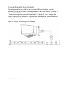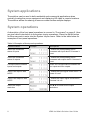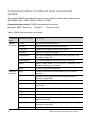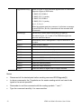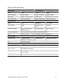
1
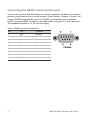
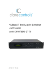
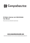
HDMI 4x4 Matrix Switcher User Guide Model CM-MT4420-HD 2014-02-382 • Rev 02 Copyright © 21MAR14 Clare Controls, Inc. All rights reserved. This document may not be copied in whole or in part or otherwise reproduced without prior written consent from Clare Controls, Inc., except where specifically permitted under US and international copyright law. Trademarks and patents HDMI 4x4 Matrix Switcher, Model CM-MT4420-HD name is a trademark of Clare Controls, Inc. Other trade names used in this document may be trademarks or registered trademarks of the manufacturers or vendors of the respective products. Manufacturer Clare Controls, Inc. 7519 Pennsylvania Ave., Suite 104, Sarasota, FL 34243, USA Version This document applies to HDMI 4x4 Matrix Switcher User Guide, Model CM-MT4420-HD version 2. Contact information 2014-02-382 • Rev 02 For contact information, see www.clarecontrols.com. Content Limitation of liability...ii Introduction...1 Features...1 Package contents...1 Product appearance...2 Front panel...2 Rear panel...3 System connection...3 Usage precautions...3 Connecting the RS232 communication port...4 Connecting with the computer...5 System diagram...6 Connection procedure...6 EDID management...7 EDID automatic handshake...7 System applications...8 System operations...8 IR controls...9 Using the IR remote...9 Communication protocol and command codes...10 Specifications...13 Panel drawing...14 Troubleshooting and maintenance...15 Safety operation guide...16 After-sales service...17 HDMI 4x4 Matrix Switcher User Guide i Limitation of liability To the maximum extent permitted by applicable law, in no event will Clare Controls, Inc. be liable for any lost profits or business opportunities, loss of use, business interruption, loss of data, or any other indirect, special, incidental, or consequential damages under any theory of liability, whether based in contract, tort, negligence, product liability, or otherwise. Because some jurisdictions do not allow the exclusion or limitation of liability for consequential or incidental damages the preceding limitation may not apply to you. In any event the total liability of Clare Controls, Inc. shall not exceed the purchase price of the product. The foregoing limitation will apply to the maximum extent permitted by applicable law, regardless of whether Clare Controls, Inc. has been advised of the possibility of such damages and regardless of whether any remedy fails of its essential purpose. Installation in accordance with this manual, applicable codes, and the instructions of the authority having jurisdiction is mandatory. While every precaution has been taken during the preparation of this manual to ensure the accuracy of its contents, Clare Controls, Inc. assumes no responsibility for errors or omissions. ii HDMI 4x4 Matrix Switcher User Guide Introduction The HDMI 4x4 is a matrix switcher with four, female HDMI inputs and four, female HDMI outputs. It enables cross-point switching from any input to any output, or all outputs, and supports 3D, 4K x 2K, and 1080P. It can be used in both residential and commercial applications to allow sharing of HD source content to multiple displays. Features HDMI 1.4a, supports 3D. HDTV compatible with high definition transmission resolution up to 1920 x 1200 at 60 Hz, and supports 1080P. HDCP compliant and DVI compatible, supporting DVI1.0. RS232 controllable EDID management. Supports firmware upgrade via USB port on front panel. HDMI switcher is controllable via RS232, IR (remote included), or the front panel. RS232 serial control port for serial commands and third-party control. RS232 controllable front panel security lock to avoid unauthorized or accidental use when the matrix is installed in an unsecure environment. Built-in gain compensation technique and synchronous signal correction technology. Switching speed is less than 200 ns (maximum). LCD screen shows real-time connection status, switching status, whether input/ output signal is with HDCP, and output resolution. Package contents 1 x serial cable 1 x IR remote 1 x remote IR receiver 1 x mounting bracket set 4 x plastic feet 1 x power supply 4 x power supply adapters 1 x user manual Notes: Please verify that the product and all the accessories are included. If not, contact your dealer. HDMI 4x4 Matrix Switcher User Guide 1 Product appearance Front panel Figure 1: Front panel of the HDMI 4x4 switcher (1) Firmware Micro USB port for updating firmware. (2) Power indicator Power 'on' indicator light. (3) IR receiver IR receive window. (4) LCD indicator Shows real-time system status. (5) INPUTS Normal mode: Input buttons range from 1 to 4. Inquire mode: Press and hold “SELECT” for 3 seconds to enter this mode to check connection status, switching status, HDCP and output resolution. Press ◄► to change menus and ▲▼ to change selection. (6) OUTPUTS Output buttons range from 1 to 4. (7) FUNCTION SELECT: Used to transfer video and audio signal (HDMI) from an input to an output. Example: To transfer both the video and audio signals from input channel 3 to output channel 4, press Input 3 + SELECT + Output 4. GLOBAL: Used to transfer video and audio signal (HDMI) of an input channel to all output channels. Example: To transfer HDMI signal from input channel 2 to all output channels, press Input 2 + GLOBAL. EDID: Used to manually control EDID management. Example: To learn the EDID data of the display on output channel 2 to input channel 3, press Input 3 + EDID + Output 2. 2 HDMI 4x4 Matrix Switcher User Guide Rear panel Figure 2: Rear panel of the HDMI 4x4 switcher (1) GROUND Connection point for equipment grounding. (2) INPUTS Four HDMI input ports. Connect them to the HDMI ports on the signal sources. (3) OUTPUTS Four HDMI output ports. Connect them to the HDMI ports on the output source devices. (4) IR EYE A .25 in. mono jack for rear connection of IR control. (5) RS232 The serial port for unit control, 9-pin female connector. Connects with a control device, such as a PC. Note: Be sure to fill in the corresponding communication protocol parameters correctly. (6) Power input Connect with the power adaptor. Indicator light is on when the switcher is powered. Be sure to use the adapter that came with the unit. System connection Usage precautions The system should be installed in a clean environment with the property temperature and humidity controlled. All devices should be connected before powering on. The Cat5e/Cat6 terminations for HDBaseT devices should be a straight-thru TIA/EIA T568B standard. HDMI 4x4 Matrix Switcher User Guide 3 Connecting the RS232 communication port You can use the front-mounted buttons to control the switcher. However, you can also perform control functions via a control system (Clare Controls, Crestron, Control4, etc.) using its RS232 communication port. The RS232 communication port is a female, 9-pin D connector (DB9). As shown in the table below, only pins 2, 3, and 5 are used. The standard functions of Tx, Rx, and Gnd apply. Table 1: RS232 connection definitions No. Pin Function 1 N/u Unused 2 Tx Transmit 3 Rx Receive 4 N/u Unused 5 Gnd Ground 6 N/u Unused 7 N/u Unused 8 N/u Unused 9 N/u Unused 4 HDMI 4x4 Matrix Switcher User Guide Connecting with the computer The switcher can be controlled via a computer COM port. However, another scenario is to use a third-party control system such, as Clare Controls, Crestron, or Control4. The RS232 protocols required for these systems are listed in the section “Communication protocol and command codes” on page 10. Use a straight-thru RS232 cable (non-null modem) to connection to these systems, unless otherwise stated by the control system’s manufacturer. Figure 3: Switcher connecting to the computer HDMI 4x4 Matrix Switcher User Guide 5 System diagram The 4x4 switcher allows up to four HDMI sources (Blu-ray DVD, tablet, digital camcorder, PC, etc.) to be routed to any or all of the four HDMI destinations (HDTV, projector, AV receiver, etc.). The diagram below shows an example of possible connections. Figure 4: System diagram Connection procedure 1. Connect the HDMI sources (e.g., DVD) to the HDMI “INPUTS” on the SWITCHER with the HDMI cables. 2. Connect the HDMI displays to the HDMI “OUTPUTS” on the SWITCHER with HDMI cables. 3. Connect the RS232 port on the SWITCHER to a control device with a serial cable (included). Control SWITCHER via the control device (e.g., a PC). 4. Connect an IR receiver to the IR Eye port (optional). 5. Connect the power adapter (included) to the switcher. 6 HDMI 4x4 Matrix Switcher User Guide EDID management The switcher has a built-in EDID management database. The EDID management system can handle the handshake automatically, manually, or it can be set to the factory default. EDID automatic handshake The EDID data management can communicate with the sources and displays automatically. When the sources and displays are connected to the switcher, they share the EDID/DCC information with the switcher. The communication solution is shown below. Figure 5: EDID communication The EDID database includes the most common display data, but not all. This is due to capability and firmware limitations. You can manually refresh the EDID data to update the EDID database. EDID management of the switcher The RS232 commands for EDID management of the switcher includes “EDIDMon.” and “EDIDMoff.” (Note the period at the end of the command.) When the command is correctly sent, all the connected displays appear blank for two to three seconds and then recover. The switcher sends the RS232 feedback command “EDIDMOn.” or “EDIDMoff.”. When the “EDIDMoff.” command is sent to the switcher, it will reset to the factory default EDID data. Note: If the output[X] does not connect to an active display, the EDID management takes no action. HDMI 4x4 Matrix Switcher User Guide 7 System applications The switcher can be used in both residential and commercial applications when centrally locating the source equipment and displaying HD video in remote locations. The switcher allows the sharing of source content across multiple displays. System operations A description of the front panel operations is covered in “Front panel” on page 2. Here we give a brief introduction to the system inquiry operations. Press the Select button for three seconds to enter into the System Inquire menu. Refer to the table below for examples of front panel operations. Table 2: Examples of front panel operations Function items Example Description Check the connection status of inputs Y means the corresponding port is connected with input device. N means it is not. Check the connection status of outputs Y means the corresponding port is connected with output device. N means it is not. Correspondence between inputs and outputs Shows the correspondence between the four inputs and four outputs. Check if the input is with HDCP Y means the input signal is with HDCP. N means it is not. Check if the output is with HDCP Y means the output signal is with HDCP, N means it is not. Check the output resolution Use ▲▼ to check all four output resolutions. 8 HDMI 4x4 Matrix Switcher User Guide IR controls Using the IR remote Figure 6: IR remote Note: A built-in IR or extended IR receiver connected to an IR Eye can control the device with this remote control. HDMI 4x4 Matrix Switcher User Guide 9 Communication protocol and command codes Through the RS232 communication port, you can control a device with a baud rate of 2400, 4800, 9600, 19200, 38400, 57600 or 115200. Communication protocol: RS232 communication protocol Baud rate: 9600 Data bit: 8 Stop bit: 1 Parity bit: none Table 3: RS232 command types and codes Command types Command codes Functions System command /*Type; Inquire the models information. /%Lock; Lock the front panel buttons on the matrix. /%Unlock; Unlock the front panel buttons on the matrix. /^Version; Inquire the version of firmware. /:MessageOff; Turn off the feedback command from the COM port. It will only show “Switch OK.” /:MessageOn; Turn on the feedback command from the COM port. Demo. Switch to Demo mode, 1->1, 2->2, 3->3 … and so on. The switching interval is two seconds. Undo. To cancel the previous operation. [x]All. Transfer signals from the input channel [x] to all output channels. All#. Transfer all input signals to the corresponding output channels, respectively. All$. Switch off all the output channels. [x]#. Transfer signals from the input channel [x] to the output channel [x]. [x]$. Switch off the output channel [x]. [x]@. Switch on the output channel [x]. All@. Switch on all output channels. [x1] V[x2]. Transfer the AV signal from the input channel [x1] to the output channel [x2]. [x1] B[x2]. Transfer the AV and IR signal from the input channel [x1] to the output channel [x2]. Status[x]. Inquire [x] output statues. Operation command 10 HDMI 4x4 Matrix Switcher User Guide Status. Inquire all outputs statues one by one. Save[Y]. Save the present operation to the preset command [Y], ranges from 0 to 9. Recall[Y]. Recall the preset command [Y]. Clear[Y]. Clear the preset command [Y]. PWON. Work in normal mode. PWOFF. Enter into standby mode and cut off the power supply. STANDBY. Enter into standby mode. /%[Y]/[X]:[Z]. HDCP management command. [Y] is for input (value: I) or output (value: O). [X] is the number of one port, if the value of X is ALL (all ports). [Z] is for working status (value: 1 or 0). Y=I & Z=1, means the input port is compliant with HDCP. Y=O & Z=1, means output with HDCP. Y=I & Z=0, means the input port is not compliant with HDCP. Y=O & Z=0, means output without HDCP. DigitAudioON[x]. Enable HDMI audio output of port x. X=1, 2, 3, 4, enable this one port. X=5, enable all the 4 ports. DigitAudioOFF[x]. Disable HDMI audio output of port x. X=1, 2, 3, 4, disable this one port. X=5, disable all the 4 ports. EDIDH[x]B[y]. Copy the EDID from output port [x] to input port [y]. If the EDID data is effective and the audio part supports not only PCM mode, then force-set it to PCM mode. If the EDID data is not effective, then set it as initialized EDID data. EDIDPCM[x]. Set the audio part of input port [x] to PCM format in EDID database. EDIDG[x]. Get EDID data from the output and display the output port number of X. EDIDMInit. Recover the factory default EDID data. EDIDM[X]B[Y]. Manually EDID switching. Copy the EDID data of output[X] to the input[Y]. EDIDUpgrade[x]. Upgrade EDID data via the RS232 port [X] is for input port, when the value of X is 5, it means to upgrade to all input ports. When the switcher gets the command, it will show a message to send EDID file (.bin file). Operations will be canceled after 10 seconds. (Note 1) Please cut off all connections of HDBaseT ports. HDMI 4x4 Matrix Switcher User Guide 11 UpgradeIntEDID[x]. Select one type of EDID data and upgrade built-in EDID data. Supports 4 types of EDID data: 1. 1080P, 2D, PCM2.0 2. 1080P, 2D, 5.1 (audio) 3. 1080P, 3D, PCM2.0 4. 1080P, 3D, 5.1 (audio) [x] = 1, 2, 3 or 4 When the switcher gets the command, it will show a message to send EDID file (.bin file). Operations will be canceled after 10 seconds. EDID/[x]/[y]. Set the built-in EDID data of input port [x] to type [y]. The value of [y] is 1, 2, 3, and 4. The EDID data types are same as mentioned above. %0801. Automatically HDCP management. If input is with HDCP, so is output. %0911. Reset to factory default. %9961. Check the system locking status. %9962. Check the status while in standby mode. %9971. Check the connection status of the inputs. %9972. Check the connection status of the outputs. %9973. Check the HDCP status of the inputs. %9974. Check the HDCP status of the outputs. %9975. Check the switching status. %9976. Check the output resolution. %9977. Check the status of digital audio of output channels. Notes Disconnect all the twisted pairs before sending command EDIDUpgrade[X]. In above commands, the [ ] symbols are for easier reading and do not need to be typed in the actual operation. Remember to end the commands with the ending symbols “.” and “;”. Type the command carefully. It is case-sensitive. 12 HDMI 4x4 Matrix Switcher User Guide Specifications Video Input Video Output Input HDMI Output HDMI Input connector Female HDMI Output connector Female HDMI Input level T.M.D.S. 2.9 V / 3.3 V Output level T.M.D.S. 2.9 V / 3.3 V Input impedance 100Ω (differential) Output impedance 100Ω (differential) Gain 0 dB Bandwidth 6.75 Gbit/s Video signal HDMI Maximum pixel clock 225 MHz Resolution range Up to 1920 x 1200 or 1080P at 60 Hz Switching speed 200 ns (max.) EDID management In-built EDID data and manual EDID management HDCP Supports HDCP 1.3, auto and manual HDCP management. Video general Control parts Control Ports Panel Control 1 IR EYE (black) 1 RS232 (9 pin female D) IR Default IR remote Front panel buttons General Power supply 12 VDC, 2 A Case dimension (W × H × D) 19.0 × 1.74 × 9.3 (48.28 × 4.41 × 23.5 cm) (1U high, full rack wide) Temperature -4 to +158ºF (-20 to +70ºC) Humidity 10% to 90% HDMI 4x4 Matrix Switcher User Guide 13 Panel drawing Figure 7: Panel drawing of the HDMI 4x4 switcher 14 HDMI 4x4 Matrix Switcher User Guide Troubleshooting and maintenance When there is color loss or no video signal output, ensure that the cables are well connected, or not broken. When EDID management does not work normally, the HDMI cable may be broken at the output end. When switching, there is a blank screen on the display, the display may not support the resolution of the video source. Switch again or manage the EDID data manually to make the resolution of the video source automatically comply with the output resolution. When a user cannot control the switcher by computer through its COM port, check the COM port number in the software. Make sure the COM port is in good condition and the communication protocol is correct. When switching and there is no output image: Ensure there is a signal at the input and the output. Ensure the output port number is the same as the controlled output port. Ensure the input/output cables are not broken, or the connectors are loose. Try another cable. If the static becomes stronger when connecting the video/audio connectors, check the grounding and make sure it is well connected, as it could damage the switcher. If you cannot control the switcher through the RS232 port, front panel buttons, or the IR remote, the unit may be broken. Return it to the dealer for repair. HDMI 4x4 Matrix Switcher User Guide 15 Safety operation guide To guarantee the reliable operation of the equipment and safety of the staff, please follow the procedures listed below. The system must be grounded properly. Do not use two blades plugs. Ensure the supply voltage is in the correct range of 100~240 V and from 50~60 Hz. Do not locate the device in a place that is abnormally hot or cold or does not have proper temperature control and ventilation. The device generates heat when running. Its environment should be well ventilated to prevent damage caused by overheating. Disconnect power in humid weather, or when left unused for long periods. Before making or removing any connections to the device, ensure that the power supply has been disconnected. Do not attempt to open the enclosure of the equipment. Do not attempt any repairs. There are no user-serviceable parts inside. Any attempt to open the equipment will result in a complete void of any warranty and may result in serious injury or death. Do not splash any chemical substances or liquids on or around the equipment. 16 HDMI 4x4 Matrix Switcher User Guide After-sales service If there appears to be problems when running the device, refer to the “Troubleshooting and maintenance” section in this manual. Return shipping costs are not covered by this warranty. You can contact Customer Support at http://support.clarecontrols.com. Please be ready to provide the following information. Product model number, version and serial number. Detailed description of the trouble issues. Description of all connections and third-party equipment being used. We offer this product with a three-year warranty, which starts from the first day you purchase this product. If, during the warranty period, the unit cannot be repaired, a suitable replacement will be issued. Replacement units will be comparable to the original. However, due to potential design changes over time, replacement units may not be identical to the unit replaced. Items not covered by this warranty. Damage caused due to incorrect usage and/or connections. Damage caused due to installation by person(s) not adequately trained in the installation of this equipment. Any attempt to open this unit and access internal components shall immediately void this warranty. Damage caused by any physical force (dropping the unit or dropping an object upon the unit, etc.). Damage caused by voltage/cycle fluctuations outside acceptable range. Damage caused by over-current, voltage spikes or lightning damage due to inadequate surge protection. A valid invoice of purchase via an authorized dealer shall be required for any warranty coverage. HDMI 4x4 Matrix Switcher User Guide 17