1
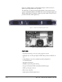
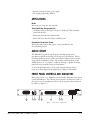
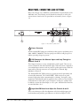
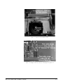
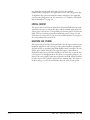
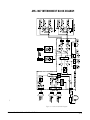
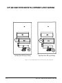
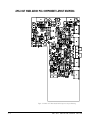
CLEAR-COM ENCORE
AMS-1027
AMPLIFIED MONITOR SPEAKER
INSTRUCTION MANUAL
AMS-1027 Amplified Monitor Speaker Instruction Manual
© 2007 Vitec Group Communications Ltd. All rights reserved.
Part Number 810284Z Rev. 1
Vitec Group Communications, LLC.
850 Marina Village Parkway
Alameda, CA 94501
U.S.A
Vitec Group Communications
7400 Beach Drive
Cambridge Research Park
Cambridgeshire
United Kingdom
CB25 9TP
Vitec Group Communications
Room 1806, Hua Bin Building
No. 8 Yong An Dong Li
Jian Guo Men Wai Ave
Chao Yang District
Beijing, P.R. China 100022
® Clear-Com, CellCom/FreeSpeak and the Clear-Com Communication Systems logo are registered trademarks of The Vitec Group
plc.
CONTENTS
OPERATION . . . . . . . . . . . . . . . . . . . . . . . . . . . . . . . . . . . . . . . 1-1
Description . . . . . . . . . . . . . . . . . . . . . . . . . . . . . . . . . . . . . . . . . . . . . . . . . . 1-1
Features . . . . . . . . . . . . . . . . . . . . . . . . . . . . . . . . . . . . . . . . . . . . . . . . . . . . . 1-2
Applications. . . . . . . . . . . . . . . . . . . . . . . . . . . . . . . . . . . . . . . . . . . . . . . . . . 1-3
Radio. . . . . . . . . . . . . . . . . . . . . . . . . . . . . . . . . . . . . . . . . . . . . . . . . . . 1-3
Television/Video Postproduction. . . . . . . . . . . . . . . . . . . . . . . . . . . . . . 1-3
Commercial Industrial Sound . . . . . . . . . . . . . . . . . . . . . . . . . . . . . . . . 1-3
Audio Circuit . . . . . . . . . . . . . . . . . . . . . . . . . . . . . . . . . . . . . . . . . . . . . . . . 1-3
Front Panel Controls and Indicators . . . . . . . . . . . . . . . . . . . . . . . . . . . . . . . 1-3
Internal Speakers . . . . . . . . . . . . . . . . . . . . . . . . . . . . . . . . . . . . . . . . . 1-4
Volume Control . . . . . . . . . . . . . . . . . . . . . . . . . . . . . . . . . . . . . . . . . . 1-4
Audio Level Bargraph Meter Displays. . . . . . . . . . . . . . . . . . . . . . . . . . 1-4
Power Indicator LED . . . . . . . . . . . . . . . . . . . . . . . . . . . . . . . . . . . . . . 1-4
Headphone Jack . . . . . . . . . . . . . . . . . . . . . . . . . . . . . . . . . . . . . . . . . . 1-4
Balance Control . . . . . . . . . . . . . . . . . . . . . . . . . . . . . . . . . . . . . . . . . . 1-4
Rear Panel Connectors and Settings. . . . . . . . . . . . . . . . . . . . . . . . . . . . . . . . 1-5
Power Connector . . . . . . . . . . . . . . . . . . . . . . . . . . . . . . . . . . . . . . . . . 1-5
XLR Connectors for Balanced Inputs and Loop-Through on Channels A
and B. . . . . . . . . . . . . . . . . . . . . . . . . . . . . . . . . . . . . . . . . . . . . . . . . . . . . . . 1-5
Input Gain/VU Meter Level Adjust for Channels A and B . . . . . . . . . . 1-5
RCA Connectors for Unbalanced Inputs on Channels A and B . . . . . . 1-6
Vol/Bal to A-Vol/B-Vol Retrofit Instructions . . . . . . . . . . . . . . . . . . . . . . . . . 1-6
INSTALLATION. . . . . . . . . . . . . . . . . . . . . . . . . . . . . . . . . . . . . . 2-1
Quick Start . . . . . . . . . . . . . . . . . . . . . . . . . . . . . . . . . . . . . . . . . . . . . . . . . . 2-1
Mounting . . . . . . . . . . . . . . . . . . . . . . . . . . . . . . . . . . . . . . . . . . . . . . . . . . . 2-1
Heat Dissipation . . . . . . . . . . . . . . . . . . . . . . . . . . . . . . . . . . . . . . . . . . . . . . 2-1
Sympathetic Vibration. . . . . . . . . . . . . . . . . . . . . . . . . . . . . . . . . . . . . . . . . . 2-1
Mechanical Bracing . . . . . . . . . . . . . . . . . . . . . . . . . . . . . . . . . . . . . . . . . . . . 2-1
Audio Connections . . . . . . . . . . . . . . . . . . . . . . . . . . . . . . . . . . . . . . . . . . . . 2-1
Electrical Interference . . . . . . . . . . . . . . . . . . . . . . . . . . . . . . . . . . . . . . . . . . 2-2
AC Power . . . . . . . . . . . . . . . . . . . . . . . . . . . . . . . . . . . . . . . . . . . . . . . . . . . 2-2
MAINTENANCE . . . . . . . . . . . . . . . . . . . . . . . . . . . . . . . . . . . . . 3-1
General Mechanical Observations . . . . . . . . . . . . . . . . . . . . . . . . . . . . . . . . . 3-1
General Audio Circuitry Observations. . . . . . . . . . . . . . . . . . . . . . . . . . . . . . 3-1
General Level Meter and Level Gain Calibration Observations . . . . . . . . . . . 3-2
Audio Circuit Description . . . . . . . . . . . . . . . . . . . . . . . . . . . . . . . . . . . . . . . 3-2
Input Section. . . . . . . . . . . . . . . . . . . . . . . . . . . . . . . . . . . . . . . . . . . . . . . 3-2
Volume Controls . . . . . . . . . . . . . . . . . . . . . . . . . . . . . . . . . . . . . . . . . . . . 3-2
AMS-1027 AMPLIFIED SPEAKER STATION
i
Limiting Circuitry . . . . . . . . . . . . . . . . . . . . . . . . . . . . . . . . . . . . . . . . . . . 3-3
Headphone and Speakers. . . . . . . . . . . . . . . . . . . . . . . . . . . . . . . . . . . . . . 3-3
AMS-1027 Interconnect Block Diagram . . . . . . . . . . . . . . . . . . . . . . . . . . . . 3-4
Left and Right Meter Driver PCA Component Layout Drawings . . . . . . . . . 3-5
AMS-1027 Left and Right Meter Driver PCA Schematic . . . . . . . . . . . . . . . 3-6
AMS-1027 Main Audio PCA Component Layout Drawing . . . . . . . . . . . . . 3-7
SPECIFICATIONS. . . . . . . . . . . . . . . . . . . . . . . . . . . . . . . . . . . . . 4-1
AMS-1027 Amplified Speaker Station . . . . . . . . . . . . . . . . . . . . . . . . . . . . . . 4-1
LIMITED WARRANTY . . . . . . . . . . . . . . . . . . . . . . . . . . . . . . . . . . . 5-I
Warranty Period. . . . . . . . . . . . . . . . . . . . . . . . . . . . . . . . . . . . . . . . . . . . . . . 5-i
Technical Support . . . . . . . . . . . . . . . . . . . . . . . . . . . . . . . . . . . . . . . . . . . . . 5-i
Warranty Repairs and Returns . . . . . . . . . . . . . . . . . . . . . . . . . . . . . . . . . . . . 5-ii
Non-Warranty Repairs and Returns. . . . . . . . . . . . . . . . . . . . . . . . . . . . . . . . 5-ii
Extended Warranty . . . . . . . . . . . . . . . . . . . . . . . . . . . . . . . . . . . . . . . . . . . . 5-ii
Service Contract . . . . . . . . . . . . . . . . . . . . . . . . . . . . . . . . . . . . . . . . . . . . . 5-iii
Liability . . . . . . . . . . . . . . . . . . . . . . . . . . . . . . . . . . . . . . . . . . . . . . . . . . . . 5-iii
ii
AMS-1027 AMPLIFIED SPEAKER STATION
IMPORTANT SAFETY INSTRUCTIONS
1.
2.
3.
4.
5.
6.
7.
Please read and follow these
instructions before operating
this product.
8.
9.
10.
11.
12.
13.
14.
15.
Read these instructions.
Keep these instructions.
Heed all warnings.
Follow all instructions.
Do not use this apparatus near water.
Clean only with dry cloth.
Do not block any ventilation openings. Install in accordance with the
manufacturer’s instructions.
Do not install near any heat sources such as radiators, heat registers, stoves,
or other apparatus (including amplifiers) that produce heat.
Do not defeat the safety purpose of the polarized or grounding-type plug. A
polarized plug has two blades, with one wider than the other. A
grounding-type plug has two blades and a third grounding prong. The wide
blade or the third prong are provided for your safety. If the provided plug
does not fit into your outlet, consult an electrician for replacement of the
obsolete outlet.
Protect the power cord from being walked on or pinched particularly at
plugs, convenience receptacles, and the point where they exit from the
apparatus.
Only use attachments/accessories specified by the manufacturer.
Use only with the cart, stand, tripod, bracket, or table specified by the
manufacturer, or sold with the apparatus. When a cart is used, use caution
when moving the cart/apparatus combination to avoid injury from tip-over.
Unplug this apparatus during lightning storms or when unused for long
periods of time.
Refer all servicing to qualified service personnel. Servicing is required when
the apparatus has been damaged in any way, such as power-supply cord or
plug is damaged, liquid has been spilled or objects have fallen into the
apparatus, the apparatus has been exposed to rain or moisture, does not
operate normally, or has been dropped.
WARNING: To reduce the risk of fire or electric shock, do not expose this
product to rain or moisture.
Please familiarize yourself with the safety symbols in Figure 1. When you see
these symbols on this product, they warn you of the potential danger of electric
shock if the main station is used improperly. They also refer you to important
operating and maintenance instructions in the manual.
AMS-1027 AMPLIFIED MONITOR SPEAKER
iii
CAUTION
RISK OF ELECTRIC SHOCK
DO NOT OPEN
This symbol alerts you to the presence of uninsulated dangerous
voltage within the product's enclosure that might be of sufficient
magnitude to constitute a risk of electric shock. Do not open
the product's case.
This symbol informs you that important operating and maintenance instructions are included in the literature accompanying
this product.
Figure 1: Safety Symbols
iv
AMS-1027 AMPLIFIED MONITOR SPEAKER
1
OPERATION
Thank you for choosing the Clear-Com AMS-1027 Amplified Speaker Station.
For optimum results, please read this entire manual before installing your
AMS-1027 station.
The AMS-1027 is a bi-amplified, self-contained, rack-mountable audio monitor
speaker that occupies only a single rack space.
This amplified speaker station features exceptional audio quality, very low
distortion, and high output power. It provides convenient, powerful,
high-quality audio monitoring capability in locations where few other monitor
speakers can fit. The specially designed 2-way speaker system will reach output
levels of 96 dB SPL at 2 feet (0.6m) without audible distortion.
The AMS-1027’s design
provides high-quality audio
monitoring, even in
high-noise environments.
The steel enclosure is magnetically shielded, allowing the speaker station to be
placed above or below a television monitor without affecting the monitor’s color
balance. Equipped with electronically balanced 3-pin XLR inputs or unbalanced
line-level RCA inputs, the AMS-1027 enables you to easily monitor a variety of
audio sources. Its input limiter minimizes speaker distortion, and separate
channel volume controls allow easy adjustment of stereo signals or two discrete
monophonic signals. The AMS-1027 has two multi-segment, LED bar-type level
displays, adjustable from the rear panel.
To achieve the extended bass response produced by the AMS-1027, the
low-frequency signals from both channels are summed into a single bass
amplifier. This amplifier drives a specially developed, baffled loudspeaker, which
is centered in the unit. The mid/high frequency drivers are mounted at opposite
ends of the AMS-1027, providing the maximum amount of stereo image
separation possible.
The Clear-Com AMS-1027 Amplified Speaker Station is a valuable accessory in
a wide variety of facilities and installations, particularly where rack space is at a
premium.
DESCRIPTION
The single-rackspace AMS-1027 permits convenient monitoring of one stereo or
two monophonic (“mono”) analog input sources, with excellent full-range
fidelity.
Two front-firing midrange-tweeter speakers and a compact high-performance
woofer are arranged in an efficient bi-amp design. The summed bass feature is
important for audible detection of “out of phase” conditions. Speaker amp
limiters prevent accidental damage to speakers from high input levels.
Front-panel volume and balance controls are standard, but can be re-configured
in the field as A volume/B volume. Ten-segment LED bargraph meters with
rear-panel input calibration provide an indication of input levels. Balanced
AMS-1027 AMPLIFIED SPEAKER STATION
1-1
inputs are on XLR connectors, with unbalanced inputs on RCA connectors.
Passive loop-through XLRs are also provided.
The AMS-1027 is completely magnetically shielded to allow interference-free
operation immediately adjacent to all CRT video monitors. Its lighter weight and
shallower-depth chassis (compared to similar-type units) makes it ideal for use in
portable and mobile vehicle applications.
Figure 1-1: AMS-1027 Amplified Speaker Station
Figure 1-2: Interior of AMS-1027 Unit
FEATURES
• Selectable monitoring of one stereo analog signal in one unit
• Although only one rack space high, the AMS-1027 produces 96 dB SPL at 2
feet
• Volume/Balance controls are standard, internally configurable as
A-volume/B-volume
• 10-segment level meters
• Headphone jack with speaker muting
• Accepts both balanced (XLR) and unbalanced (RCA) inputs
• XLR loop-through connectors
• Blowout-proof speakers
• Lightweight and shallow-depth chassis
1-2
AMS-1027 AMPLIFIED SPEAKER STATION
• Internal universal AC mains power supply
• Thoroughly magnetically shielded
APPLICATIONS
Radio
Monitoring incoming and outgoing feeds
Television/Video Postproduction
• Confidence/cuing monitoring for all types of ATRs and VTRs in machine
rooms and edit bays
• Monitoring network and transmitter feeds
• ENG, SNG and other OB vehicles and EFP systems
Commercial Industrial Sound
Monitoring audio feeds in theme parks, security installations, and
teleconferencing systems
AUDIO CIRCUIT
The AMS-1027’s popular bi-amp design provides high-quality audio
reproduction, ideal for monitoring even in high noise environments. The two
front-firing midrange-tweeter speakers and compact high-performance woofer,
along with the summed bass feature, offer accurate sound reproduction and
audible detection of “out of phase” conditions. Damage to speakers from high
input levels are prevented by using in-circuit limiters.
For more detailed information, see the audio circuit description and the
interconnect block diagram in the Maintenance Chapter of this manual.
FRONT PANEL CONTROLS AND INDICATORS
Please refer to Figure 1-3 to familiarize yourself with the AMS-1027’s front-panel
controls and indicators. The following sections describe the functions of each of
the various controls and indicators found on the front panel and are referenced,
by number, to Figure 1-3.
Amplified
Monitor Speaker
AMS-1027
1
2
3
4
5
1
6
3
1
Figure 1-3: Front Panel of AMS-1027
AMS-1027 AMPLIFIED SPEAKER STATION
1-3
1
Internal Speakers
The AMS-1027’s internal speaker system is comprised of two mid/high-range
speakers (left and right) and one woofer speaker (center). The two side channel
speakers reproduce, in stereo, only the mid and high frequencies, while the center
woofer speaker reproduces the low frequencies summed from both the left and
right channels.
2 Volume Control
The volume-control knob adjusts the loudness of the audio reproduced by the
internal speakers or connected headphone.
3 Audio Level Bargraph Meter Displays
Audio levels for the left and right channels are displayed via two 10-segment
LED bargraph meters on the respective sides of the front panel. Dynamic range
for these meters is 23 dB. Gain calibration for these meters is via two recessed
trim pots on the rear panel (see “Rear Panel Connectors and Controls” later in
this chapter for more information). Meters are factory set for VU mode and gain
at 0 = +4 dBu.
The AMS-1027’s front-panel
controls and indicators are
illustrated in Figure 1-3.
4
Power Indicator LED
The power indicator LED signals the operating condition of the power supply.
The LED glows green to indicate the AMS-1027 is connected to mains power
and an operating voltage is present.
5 Headphone Jack
For critical listening or for listening in high noise environments, use the stereo
headphone feature rather than the internal speakers. The left and right channels
are separated for stereo listening in the headphones. When you plug in
headphones, the internal speakers will mute. This jack accepts the standard
1/4-inch tip-ring-sleeve stereo plug.
6 Balance Control
This control pans the volume balance between the left and right speakers. If the
balance is adjusted hard left or right, a slight L+R channel mix is retained (only
in low bass frequencies) so that phase discrepancies can be discerned.
Separate left and right volume controls may be selected via internal jumpers in
lieu of a balance control. For instructions on how to perform this retrofit, see
“VOL/BAL to A-VOL/B-VOL Retrofit Instructions” on page 1-6.
1-4
AMS-1027 AMPLIFIED SPEAKER STATION
REAR PANEL CONNECTORS AND SETTINGS
Please refer to Figure 1-4 to familiarize yourself with the rear panel features of the
AMS-1027 unit. The following sections describe the functions of each of the
various features found on the rear panel and are referenced, by letter, to Figure
1-4.
B
100-240-VAC
50/60 Hz 1.0A
AMS-1027
A
C
D
C
Figure 1-4: Rear Panel of AMS-1027
A
Power Connector
Attach a standard IEC-320 power cord between this connector and mains power
(100 - 240VAC, 50/60 Hz). The front panel power LED (6) will glow green to
indicate operating voltages are present.
B
XLR Connectors for Balanced Inputs and Loop-Through on
Channels A and B
These inputs are meant to receive standard analog audio signals. There are two
sections; Channel A (left) and Channel B (right), with each section comprised of
one standard input connector and one passive loop-through connector. Both the
input and loop-through connectors are configured for a balanced, high
impedance connection.
The “BALANCED IN” XLR connectors are panel mounted 3-pin females and
are internally terminated. The “LOOP-THRU” XLR connectors are panel
mounted 3-pin males and are unterminated (for “chaining” the signal to other
equipment). If unbalanced signals are applied to these connectors, they should be
connected between either pin 2 or pin 3 and pin 1. In that case, a jumper must
be added to connect the unused input (3 or 2) to pin 1. All balanced connections
are wired with Pin 2 “hot.”
C
Input Gain/VU Meter Level Adjust for Channels A and B
These recessed trim pots allow the adjustment of the left and right input gain
levels simultaneously with the gain calibration of the left and right VU level
AMS-1027 AMPLIFIED SPEAKER STATION
1-5
meters. There are two trim pots; one for Channel A (left) and one for Channel B
(right). This dual adjustment configuration aids in the calibration of the meters
with the input gain.
Adjustment is between -10dBu and +10dBu (nominal). Gain increases as the
pots are turned clock-wise. These controls may be accessed with a small flat-blade
screwdriver.
Note: Do not force the trim pots past their stop points as this will damage the
unit.
D
RCA Connectors for Unbalanced Inputs on Channels A and B
These inputs are meant to receive standard, unbalanced, -10 dBu line level audio
signals. Both are configured for an unbalanced, high impedance connection.
Panel-mounted female RCA connectors are used.
VOL/BAL TO A-VOL/B-VOL RETROFIT INSTRUCTIONS
You can reconfigure the unit
to give it two separate
volume controls. Instructions
are included in this chapter.
The AMS-1027 is configured at the factory with Volume/Balance controls. To
change the function of the Volume/Balance controls on the front panel to an “A”
Volume/“B” Volume (left and right) configuration, follow the instructions
below:
1. Disconnect the unit from AC and all line connections.
2. Remove the AMS-1027’s top cover.
3. Locate the Vol/Bal harness (flat cable) running from the right-side front panel
PCB (See Figure 1-5).
4. On the Main PCB, unplug the harness ribbon cable connector from J18 and
plug it into J16 (See Figure 1-6).
5. Replace the AMS-1027’s top cover and reconnect.
Remember that the front panel text will still refer to the right-side control as a
balance. You may want to place a label over the old text of both knobs to indicate
their new function as “A” and “B” (or Left and Right) volume controls.
1-6
AMS-1027 AMPLIFIED SPEAKER STATION
Figure 1-5: Locate the volume/balance cable
Figure 1-6: Unplug the cable from jumper 18 and plug it into jumper 16
AMS-1027 AMPLIFIED SPEAKER STATION
1-7
2
INSTALLATION
QUICK START
You can install the AMS-1027 in four easy steps:
1. Slide and secure the unit into the rack.
2. Connect the audio signals to the XLR or RCA input connectors.
3. Plug the unit’s supplied IEC-320 power cord into the AC mains.
4. Configure volume controls and set level meters (if required).
MOUNTING
You install the AMS-1027 in
four easy steps.
The unit should be mounted where convenient for operating, ideally at
approximately ear level for best high-frequency response. Its superior magnetic
shielding eliminates concerns about locating it adjacent to most types of CRT
monitors, including even high-resolution color monitors.
HEAT DISSIPATION
Heat dissipated by the speaker amps is conducted directly to the left side of the
chassis; no special considerations for cooling are necessary as long as the ambient
temperature inside the rack area does not exceed approximately 60° C (140° F).
SYMPATHETIC VIBRATION
You can locate an
AMS-1027 next to most
types of CRT monitors
because of its superior
magnetic shielding.
Sympathetic vibration from other equipment (cables, etc.) in the rack may be
serious enough to interfere with the unit’s sound quality in the listening area. The
use of thin card stock and/or felt or foam weather-stripping type materials
between adjacent vibrating surfaces, or tying up loose cables, and so on, may be
required to stop vibrations external to the unit.
MECHANICAL BRACING
Even though the unit is fairly heavy, the chassis is securely attached to the front
panel at eight points along its surface, not just at the four corners of the chassis
ears. This feature will reduce or eliminate rear bracing requirements in many
mobile/portable applications. The weight of internal components are distributed
fairly evenly around the unit.
AUDIO CONNECTIONS
Connection of the audio feeds is straightforward. Refer to the interconnect block
diagram in the Maintenance Chapter for clarification of the general signal paths
into and out of the AMS-1027 unit.
AMS-1027 AMPLIFIED SPEAKER STATION
2-1
ELECTRICAL INTERFERENCE
As with any audio equipment, maximum immunity from electrical interference
requires the use of balanced, shielded cable; however, satisfactory results can
sometimes be obtained without it. The internal circuitry common is connected
to the chassis. Unbalanced sources may also be applied to the balanced inputs.
The gain is 6 dB greater with a single-ended source connected across both “hot”
terminals than when connected between either pin 2 or 3 and common. Note
that the unused input terminal of a balanced input should be connected to
common, rather than being left floating, to insure best immunity to noise.
AC POWER
The unit's AC mains connection is via a standard IEC inlet, with safety ground
connected directly to the unit's chassis. The universal AC input (100-240VAC,
50/60Hz) switching power supply is a self-resetting sealed type, with automatic
over-voltage and over-current shutdown. There is no user-replaceable fuse in
either the primary or secondary circuit.
2-2
AMS-1027 AMPLIFIED SPEAKER STATION
3
MAINTENANCE
GENERAL MECHANICAL OBSERVATIONS
Elimination of cabinet and component sympathetic vibrations (resonances)
requires considerable attention to mechanical details. Because of this, and the
physical constraints of the speaker’s acoustic enclosures, even minor changes to
any of the mechanical details of the unit can seriously impair its acoustic
performance. This especially applies to the speaker baffles. If mechanical work on
the unit is necessary, be sure to make adequate notes to permit accurate
reassembly.
If you disassemble the
AMS-1027 unit, you may
impair the unit’s magnetic
shielding.
Due to our unique method of shielding, the magnetic shielding is usually
degraded slightly by any disassembly of the unit, except removal of the rear panel.
Almost any maintenance or repair will require removal of the cover. If an
immediately adjacent video monitor shows magnetic interference after
reassembly of the unit, it must be returned to the factory to restore the shielding
completely.
Refer to the overall unit interconnect block diagram which appears later in this
chapter for assistance in tracing the signal path through the detailed schematic.
GENERAL AUDIO CIRCUITRY OBSERVATIONS
Since a single-sided power supply is used, all amplifier sections are “biased” with
a 1/2-supply reference, so all opamp signal terminals on the main board should
have a DC level of 12 ± 0.7V.
Signal inputs to the main audio board are via the balanced XLR analog inputs or
unbalanced RCA inputs.
Signal feed points for level meters and the phase indicator are immediately after
the input stage, and before the volume control section.
The signal pick-off for the headphones is after the volume and balance controls.
Analog switches mute the speakers, controlled by circuitry, which senses
connection of headphones to the jack.
The power amps are attached to an aluminum heatsink plate (which is also
connected to the circuit common for these devices). The heatsink plate forms an
operational module separate from the chassis, which allows access to the solder
side of the circuit board while power is applied to the circuitry. To avoid thermal
shutdown of the power amp(s), they should not be operated without their tabs
being fastened to the heatsink plate.
Variations in the frequency response of different production runs of drivers has
sometimes required minor adjustments in the equalization/crossover components
in individual runs of units. Some of these components may have values slightly
different than those indicated in the schematic, which are the nominal ones. If
AMS-1027 AMPLIFIED SPEAKER STATION
3-1
any of the drivers (speakers) are replaced, it may be necessary to change some of
these components to achieve maximum flatness of response.
The operating threshold of the woofer limiter is critical to both satisfactory
reproduction of musical transients and preventing damage to, or destruction of,
the speaker itself. The side speaker output limiter circuits are similarly important,
though not as critically adjusted.
Note: The woofer power amps are arranged in a bridge configuration; care must
be taken to avoid letting either speaker terminal contact the chassis (common) or
the grounded lead of any test equipment so as not to short out the power amps.
The side speaker outputs are single-ended, so these precautions are not as
important for them.
GENERAL LEVEL METER AND LEVEL GAIN CALIBRATION OBSERVATIONS
The display driver circuit
provides a total of 23 dB of
visual audio level indication
via a 10-segment LED
bargraph.
The display driver circuit provides a total of 23 dB of visual audio level
indication via a 10-segment LED bargraph. Meter calibration adjustments are via
two recessed trim pots (right and left) on the rear panel labeled “LEVEL ADJ.”
Please note that these trim pots also simultaneously adjust the gain at the left and
right input connectors. The range of adjustment is -10dBu to +10dBu
(nominal). The driver PCB connects the LEDs in the bargraph in a series string.
The anode of the LED corresponding to the lowest input level (-20) is connected
to V+, with the other 9 LEDs following, and the outputs of the bargraph
connected to the node between each LED.
Note: Only one output of the bargraph is active (low) at any one time, so if the
LED string is “broken” (open) at any point, the bargraph will go OFF whenever
the input level is at or above the level corresponding to the break.
AUDIO CIRCUIT DESCRIPTION
INPUT SECTION
The balanced input is buffered by a differential input of the audio signal to dual
op amp ICs 1a and 2a. The output of ICs 1b and 2b goes through P1 and P2,
which simultaneously sets the input volume gain and VU meter driver levels and
then proceeds to the input of the quad VCA (U4) after receiving a slight treble
boost. The output from the quad VCA (U4) then goes to a dual rectifier (IC5),
used to drive the VU meters. This setup also allows the inclusion of unbalanced
signals via the RCA jacks on the rear panel.
VOLUME CONTROLS
Volume controls are implemented through a quad VCA chip (U4). The control
potentiometer for each VCA is buffered by IC3 and IC4. Sections A and B of the
dual IC each buffer one volume control. Counter-clockwise rotation of the
volume pot decreases the wiper voltage causing the IC3A and IC4A output to
AMS-1027 AMPLIFIED SPEAKER STATION
3-2
rise, which decreases the audio level of the VCA. For the standard
volume/balance configuration, the right hand control board is plugged into J18.
To implement the optional A volume/B volume configuration, the right hand
control board is plugged into J16. For instructions, see “Vol/Bal to A-Vol/B-Vol
Retrofit Instructions” on page 1-6.
LIMITING CIRCUITRY
The output of the four VCAs are summed into IC8A and IC8B where the audio
waveform’s conversion to voltage takes place, and the rectified output from each
of these stages is the input to a corresponding non-inverting section of IC3A and
IC4A. These non-inverting sections develop limiting control voltages for each
VCA section. A voltage above 2 volts across D2 and D6 will cause a lower gain in
the corresponding section of the VCA.
HEADPHONE AND SPEAKERS
The output of the four VCAs (IC8A and IC8B) is also the input circuitry for the
headphone amplifier as well as the input of the speaker amplifiers, through IC7.
Signals from IC8 are passed through IC10 (highpass filters A and B) for the side
speaker amps, IC12A and IC11B. The input and output of these filters are
summed through resistor packs SP9 and SP8 into the VCA (U4) on pin 10. Due
to the inversion of the highpass filters, this allows a corresponding lowpass to be
derived. The control signal for this phase is derived from IC4B, which is rectified
from the output of IC9, which is used as the bass summing amp. The output of
the driver stage goes to IC11A and IC12B to drive the center woofer speaker.
3-3
AMS-1027 AMPLIFIED SPEAKER STATION
AMS-1027 INTERCONNECT BLOCK DIAGRAM
7
Figure 3-1: Interconnect Block Diagram
AMS-1027 AMPLIFIED SPEAKER STATION
3-4
LEFT AND RIGHT METER DRIVER PCA COMPONENT LAYOUT DRAWINGS
Left Meter Driver PCA Layout Drawing
Right Meter Driver PCA Layout Drawing
Figure 3-2: Left and Right Meter Driver PCA Component Layout Drawings
3-5
AMS-1027 AMPLIFIED SPEAKER STATION
AMS-1027 LEFT AND RIGHT METER DRIVER PCA SCHEMATIC
Figure 3-3: Left and Right Meter Driver Schematic
AMS-1027 AMPLIFIED SPEAKER STATION
3-6
AMS-1027 MAIN AUDIO PCA COMPONENT LAYOUT DRAWING
Figure 3-4: AMS-1027 Main Audio PCA Component Layout Drawing
3-7
AMS-1027 AMPLIFIED SPEAKER STATION
J2
J3
RCA JACK
XLRM
XLRF
1
3
J1
1
2
2
1
3
J4
XLRF
P2
10K
2
J5
XLRM
2
3
1
1
3
2
2
2
2
RCA JACK
J6
2
3
1
1
3
2
1
3
3
3
3
1
1
2
2
1
1
R89
47K
R88
47K
R86
47K
R87
47K
C3
.47u
C29
C24
100p
C27
.47u
C8
100p
.47u
C5
2
3
2
3
C30
100pC32
C1
100p
C43
2
C68
JP7
HEADER 2
JP6
2
1
HEADER 2
220uf
1
+
220uf
R2
4.7k
C50
.1u
+C41
150U
220UF
R50
2.7OHM
R47 IC12B
100KLM4765
1
MISC1
R39
2.7OHM
R36 IC12A
100K LM4765
3
IC11B
LM4765
1
R60
100K
C65
.1u
R64
2.7
C74
.1U
C66 +
150U
IC11A
LM4765
3
R51
100K
R57
2.7OHM
+ C61
150U
C57
.1u
+C54
150U
1N5401
D20
C25
100p
C2
100p
JP4
1
2
3
4
HEADER 4
R21
10K
R22
10K
IC2A
LF353
1
R13
4.7k
IC1A
LF353
1
C34
100U
R72
2.2 K 5W R27
1 OHM
HEADER 2
1
2
HEADER 2
H1
SIPI4
.4 7u
R20
10K
SP7
47k
R8
10K
SIPI4
SP2
47k
8
P1
10K
1
2
4
8
4
+
-
+
R37
10K
7
LF353
IC2B
IC1B
7
LF353
M
- 12
+ 13
S
M
- 12
+ 13
S
C95 +
10u
M
- 7
+ 8
S
MISC2
PAD4-40
C87 +
1U
R61
10K
15k
R79
15 k
R62
3
SIPI4
SIPI4
SP9
33K
C69
C76 +
10u
.1U
C55
.47u
6
5
R34
75k
IC10B
LF353
7
.47u
C63
1N4148
D16
1N4148
D15
2
3
C35
560PF
560 PF
C28
C21
560 PF
C16
560 PF
C26
560PF
IC10A
1
LF353
SP6
470OHM
SP8
33K
C89
.001u
C91
00pf
22K
R56
R55
10K
C86 +
1U
C92
00pf
.1U
.001u
C47
C88
.47u
R49
22K
R80
15k
R81
15k
SP5
68K
220PF SIPI4
C19
C18
.47u
C10
1
220PF
C15
C85 +
1U
R48
10K
C94 + C49 +
10u
1U
M
- 7
+ 8
S
6
5
R11
2.7K
6
5
R1
2.7K
4
8
4
8
4
R40
8.2K
C44
.022u
C81 +
10u
IC3B
7
LF353
BIAS
R15
2.2k R17
47 OHM
C40
.022u
6
5
8
LF353
IC9A
1
R63
75k
U4
SSM2164
SP10
33K
C58
560 PF
2
3
R41
8.2K
R65
8.2K
C71
.022u
.022u
C67
6
5
R66
8.2K
C72 C73
.022u .022u
C46
C45
.022u .022u
R23
4.7k
SIPI4
C 62
.022u
LF353
IC9B
7
C11
.22U C12
.22U
IC4A
1
LF353
IC4B
7
LF353
C90
.22U
3
2
LF353
1 IC3A
2
3
R42
47K
IC8A
1
LF442
6
5
IC8B
7
LF442
C51 100p
2
3
R26
47K
C36 100p
R9
150k
C93 +
10u
C23
.22U
C17
.22U
R43
2.2 K
2.2 K
D6
BIAS
.1u
C52
.1u
C37
1N4148
D19
1N4148
D7
1
1N4148
D9
B I AS
LED
R18
470K
2
1N4148
D3
SP3
10K
1
1N4148
D5
D2
R6 LED
150k
2
SP1
10K
C14
10Uf
C7
.2 2U
R28
C33
C82 +
.47u 10u
6
5
2
3
C4
10Uf
.47u
C42
.47u
C39
C6
.2 2U
R5
R14
33K
6
5
2
3
D1
R4
330K
R59
10K
R58
22K
R53
10K
R54
10K
R44
22K
IC7B
6
7
5
NE5532
C53
100p
IC7A
1
NE5532
R29
22K
R35
C59
2 20uf
47 OHM
R46
47OHM
R16
1.5K
R74
3.3K
22C600 uf
LEDR30 K
3.3
6
5
+C80
47U
+ C79
47U
+C22
2.2 UF
R73
3.3 K
J17
1
2
3
4
5
6
7
8
9
10
11
12
13
14
15
16
CON16A D14
2
1
D11
1N4148
IC5A
1
R7
1.5 K
+
C9
2.2 UF
LF353
1N4148
D10 330K
R10
1N4148
1N414 8
IC5B
LF353
D4
7
C38
100p
2
3
J10
1
2
3
4
5
CON5
BIAS
R45
10K
BIAS
R33
10K
.2 2U
C20
33K
AMS-1027 Main Audio PCA Schematic
1
V+
R19
100K
SP4
10K
C13
.22U
1
4
8
4
8
8
4
8
+
-
1
2
1
2
6
5
4
9
15
11
10
4
14
2
6
5
4
9
15
11
8
GND 8
IN2 7
CONT2 6
5
OUT2 4
OUT1 3
CONT1 2
IN1
MODE 1
VIN3
CONT3
OUT3
OUT4
CONT4
IN4
V+
9
10
11
12
13
14
15
16
+
-
10
4
14
4
+
-
4
+
-
+
-
1
+
-
+
-
8
4
+
-
8
+
-
4
+
8
4
+
8
4
8
4
+
-
4
D8
1N414 8
D13
1N414 8
4
8
+
-
8
IC6B
7
LM358
2
3
4
8
+
-
+
-
+
+
-
2vc
+
-
+
-
AMS-1027 AMPLIFIED SPEAKER STATION
+
+
Figure 3-5: AMS-1027 Main Audio PCA Schematic
3-8
C83
560PF
IC6A
1
LM358
R77
4.7k
R78
47OHM +
C84
00pf
J16
2
1
3
4
6
5
7
8
9
10
12
11
14
13
16
15
CON16A
R32
6.8K
R25
6.8K
R90
1.2 k
2
4
6
8
10
12
14
16
CON16A
J18
1
3
5
7
9
11
13
15
4
SPECIFICATIONS
AMS-1027 AMPLIFIED SPEAKER STATION
0 dBu is referenced to 0.775 volts RMS
Input impedance
Input level for full output
(volume full on)
Meter calibration range
Hum and noise
Acoustic freq. response
Maximum acoustic output
Electrical distortion
Acoustic distortion
(speaker outputs)
Magnetic shielding
Power Amp Output to Speakers
Channel Separation
Power Supply
AMS-1027 AMPLIFIED SPEAKER STATION
100KΩ balanced
0dBu balanced, -10dBu unbalanced
-10 to +10dBu for “0” reading
Better than -70dB below full output
60 Hz to 16 KHz (± 6dB)
96dB SPL at 2 feet
Less than 0.3% at any level below limiting
threshold
Typically <2% at any level below limiting,
100 Hz–15 KHz
Less than 0.3 Gauss any adjacent surface
Average 5 watts per L/R channel; 10 watts
woofer
Better than 70dB @ 1 KHz
Universal AC input (100-240 V)
UL/CSA approved
4-1
Power Consumption
Operating Temperature Range
Connectors
Chassis dimensions (H x W x D)
Weight
40 watts
Does not exceed approximately 60° Celsius
(140° Fahrenheit)
Balanced: XLR (with loop-through)
Unbalanced: RCA
1.75 x 19 x 9 inches
(44.5 x 483 x 229 mm)
7.5 lbs. (3.4 kg)
Notice About Specifications
While Clear-Com makes every attempt to maintain the accuracy of the
information contained in its product manuals, that information is subject to
change without notice. Performance specifications included in this manual are
design-center specifications and are included for customer guidance and to
facilitate system installation. Actual operating performance may vary.
AMS-1027 AMPLIFIED SPEAKER STATION
4-2
4-3
AMS-1027 AMPLIFIED SPEAKER STATION
LIMITED WARRANTY
Vitec Group Communications (VGC) warrants that at the time of purchase, the
equipment supplied complies with any specification in the order confirmation
when used under normal conditions, and is free from defects in workmanship
and materials during the warranty period.
VGC offers 24 x 7 customer
support if you have an
Extended Warranty or
Service Contract.
Return Material
Authorization (RMA)
numbers are required for all
returns.
Both warranty and
non-warranty repairs are
available.
During the warranty period VGC, or any service company authorized by VGC,
will in a commercially reasonable time remedy defects in materials, design, and
workmanship free of charge by repairing, or should VGC in its discretion deem it
necessary, replacing the product in accordance with this limited warranty. In no
event will VGC be responsible for incidental, consequential, or special loss or
damage, however caused.
WARRANTY PERIOD
The product may consist of several parts, each covered by a different warranty
period. The warranty periods are:
• Cables, accessories, components, and consumable items have a limited
warranty of 90 days.
• Headsets, handsets, microphones, and spare parts have a limited warranty of
one year.
• UHF wireless IFB products have a limited warranty of one year.
• UHF wireless intercom systems have a limited warranty of three years.
• All other Clear-Com and Drake brand systems and products, including
beltpacks, have a limited warranty of two years.
The warranty starts at the time of the product’s original purchase. The warranty
start date for contracts which include installation and commissioning will
commence from the earlier of date of the Site Acceptance Test or three months
from purchase.
TECHNICAL SUPPORT
To ensure complete and timely support to its customers, VGC’s User Support
Center is staffed by qualified technical personnel. Telephone and email technical
support is offered worldwide by the User Support Center.
The User Support Center is available to VGC’s customers during the full course
of their warranty period. Telephone support during the warranty period will be
offered at no charge between 09:00 and 17:00 according to the customer’s local
time zone.
In addition, for customers who purchase an Extended Warranty or Service
Contract, 24-hour customer support is offered immediately upon purchase of
WARRANTY
i
such agreement. For more information, contact your authorized dealer,
distributor, or sales representative.
Instructions for reaching VGC’s User Support Centers are given below.
Telephone for Europe, Middle East and Africa: +49 40 6688 4040
Telephone for the Americas and Asia: +1 510 337 6600
Email: [email protected]
Once the standard warranty period has expired, the User Support Center will
continue to provide telephone support if you have purchased an Extended
Warranty or Service Contract. In these cases, you will have access to telephone
support 24 hours per day, 7 days per week.
WARRANTY REPAIRS AND RETURNS
Before returning equipment for repair, contact a User Support Center to obtain a
Return Material Authorization (RMA). VGC representatives will give you
instructions and addresses for returning your equipment. You must ship the
equipment at your expense, and the support center will return the equipment at
VGC’s expense.
For out-of-box failures, use the following contact information:
Europe, Middle East and Africa
Tel: +44 1223 815000 Email: [email protected]
North America, Canada, Mexico, Caribbean & US Military
Tel: +1 510 337 6600 Email: [email protected]
Asia Pacific & South America
Tel: +1 510 337 6600 Email: [email protected]
VGC has the right to inspect the equipment and/or installation or relevant
packaging.
NON-WARRANTY REPAIRS AND RETURNS
For items not under warranty, you must obtain an RMA by contacting the User
Support Center. VGC representatives will give you instructions and addresses for
returning your equipment.
You must pay all charges to have the equipment shipped to the support center
and returned to you, in addition to the costs of the repair.
EXTENDED WARRANTY
If you purchase an Extended Warranty, you are also given access free of charge to
the User Support Center 24 hours a day, 7 days a week.
You can purchase an extended warranty at any time during the first two years of
ownership of the product. The purchase of an extended warranty extends to five
ii
WARRANTY
years the warranty of any product offered with a standard two-year warranty.
The total warranty period will not extend beyond five years. Any purchase of an
extended warranty provides 24 x 7 customer support in addition to the warranty
immediately upon purchase of the warranty extension.
Note: VGC does not offer warranty extensions on UHF wireless intercom
systems, or on any product with a 1-year or 90-day warranty.
SERVICE CONTRACT
VGC also offers service contracts that provide 24 x 7 telephone support, advance
replacements, training, proactive maintenance, on-site visits, and no charge for
repair or replacement of equipment. For more information, contact your
authorized dealer, distributor, or sales representative.
LIABILITY
THE FOREGOING WARRANTY IS VGC'S SOLE AND EXCLUSIVE
WARRANTY. THE IMPLIED WARRANTY OF MERCHANTABILITY
AND FITNESS FOR A PARTICULAR PURPOSE AND ANY OTHER
REQUIRED IMPLIED WARRANTY SHALL EXPIRE AT THE END OF
THE WARRANTY PERIOD. THERE ARE NO OTHER WARRANTIES
(INCLUDING WITHOUT LIMITATION WARRANTIES FOR
CONSUMABLES AND OTHER SUPPLIES) OF ANY NATURE
WHATSOEVER, WHETHER ARISING IN CONTRACT, TORT,
NEGLIGENCE OF ANY DEGREE, STRICT LIABILITY OR OTHERWISE,
WITH RESPECT TO THE PRODUCTS OR ANY PART THEREOF
DELIVERED HEREUNDER, OR FOR ANY DAMAGES AND/OR LOSSES
(INCLUDING LOSS OF USE, REVENUE, AND/OR PROFITS). SOME
STATES DO NOT ALLOW THE EXCLUSION OR LIMITATION OF
INCIDENTAL OR CONSEQUENTIAL DAMAGES OR THE
LIMITATION ON HOW LONG AN IMPLIED WARRANTY LASTS, SO
THE ABOVE LIMITATIONS MAY NOT APPLY TO YOU. IN ANY
EVENT, TO THE MAXIMUM EXTENT PERMITTED UNDER
APPLICABLE LAW, VGC'S LIABILITY TO CUSTOMER HEREUNDER
SHALL NOT UNDER ANY CIRCUMSTANCES EXCEED THE COST OF
REPAIRING OR REPLACING ANY PART(S) FOUND TO BE
DEFECTIVE WITHIN THE WARRANTY PERIOD AS AFORESAID.
This warranty does not cover any damage to a product resulting from cause other
than part defect and malfunction. The VGC warranty does not cover any defect,
malfunction, or failure caused beyond the control of VGC, including
unreasonable or negligent operation, abuse, accident, failure to follow
instructions in the manual, defective or improperly associated equipment,
attempts at modification and repair not approved by VGC, and shipping
damage. Products with their serial numbers removed or defaced are not covered
by this warranty.
This warranty does not include defects arising from installation (when not
performed by VGC), lightning, power outages and fluctuations, air conditioning
failure, improper integration with non-approved components, defects or failures
WARRANTY
iii
of customer furnished components resulting in damage to VGC provided
product.
This limited warranty is not transferable and cannot be enforced by anyone other
than the original consumer purchaser.
This warranty gives you specific legal rights and you may have other rights which
vary from country to country.
iv
WARRANTY