1
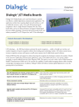
Dialogic® 1000 and 2000
Media Gateway Series
Getting Started Guide
September 2011
64-0259-06
Copyright and Legal Notice
Copyright © 2007-2011 Dialogic Inc. All Rights Reserved. You may not reproduce this document in whole or in part without permission in writing from Dialogic Inc.
at the address provided below.
All contents of this document are furnished for informational use only and are subject to change without notice and do not represent a commitment on the part of
Dialogic Inc. and its affiliates or subsidiaries (“Dialogic”). Reasonable effort is made to ensure the accuracy of the information contained in the document.
However, Dialogic does not warrant the accuracy of this information and cannot accept responsibility for errors, inaccuracies or omissions that may be contained
in this document.
INFORMATION IN THIS DOCUMENT IS PROVIDED IN CONNECTION WITH DIALOGIC® PRODUCTS. NO LICENSE, EXPRESS OR IMPLIED, BY ESTOPPEL
OR OTHERWISE, TO ANY INTELLECTUAL PROPERTY RIGHTS IS GRANTED BY THIS DOCUMENT. EXCEPT AS PROVIDED IN A SIGNED AGREEMENT
BETWEEN YOU AND DIALOGIC, DIALOGIC ASSUMES NO LIABILITY WHATSOEVER, AND DIALOGIC DISCLAIMS ANY EXPRESS OR IMPLIED
WARRANTY, RELATING TO SALE AND/OR USE OF DIALOGIC PRODUCTS INCLUDING LIABILITY OR WARRANTIES RELATING TO FITNESS FOR A
PARTICULAR PURPOSE, MERCHANTABILITY, OR INFRINGEMENT OF ANY INTELLECTUAL PROPERTY RIGHT OF A THIRD PARTY.
Dialogic products are not intended for use in certain safety-affecting situations. Please see http://www.dialogic.com/about/legal.htm for more details.
Due to differing national regulations and approval requirements, certain Dialogic products may be suitable for use only in specific countries, and thus may not
function properly in other countries. You are responsible for ensuring that your use of such products occurs only in the countries where such use is suitable. For
information on specific products, contact Dialogic Inc. at the address indicated below or on the web at www.dialogic.com.
It is possible that the use or implementation of any one of the concepts, applications, or ideas described in this document, in marketing collateral produced by or
on web pages maintained by Dialogic may infringe one or more patents or other intellectual property rights owned by third parties. Dialogic does not provide any
intellectual property licenses with the sale of Dialogic products other than a license to use such product in accordance with intellectual property owned or validly
licensed by Dialogic and no such licenses are provided except pursuant to a signed agreement with Dialogic. More detailed information about such intellectual
property is available from Dialogic’s legal department at 1504 McCarthy Boulevard, Milpitas, CA 95035-7405 USA. Dialogic encourages all users of its
products to procure all necessary intellectual property licenses required to implement any concepts or applications and does not condone or
encourage any intellectual property infringement and disclaims any responsibility related thereto. These intellectual property licenses may differ from
country to country and it is the responsibility of those who develop the concepts or applications to be aware of and comply with different national
license requirements.
Dialogic, Dialogic Pro, Dialogic Blue, Veraz, Brooktrout, Diva, Diva ISDN, Making Innovation Thrive, Video is the New Voice, VisionVideo, Diastar, Cantata,
TruFax, SwitchKit, SnowShore, Eicon, Eiconcard, NMS Communications, NMS (stylized), SIPcontrol, Exnet, EXS, Vision, PowerMedia, PacketMedia, BorderNet,
inCloud9, I-Gate, ControlSwitch, NaturalAccess, NaturalCallControl, NaturalConference, NaturalFax and Shiva, among others as well as related logos, are either
registered trademarks or trademarks of Dialogic Inc. and its affiliates or subsidiaries. Dialogic’s trademarks may be used publicly only with permission from
Dialogic. Such permission may only be granted by Dialogic’s legal department at 1504 McCarthy Boulevard, Milpitas, CA 95035-7405 USA. Any authorized use of
Dialogic’s trademarks will be subject to full respect of the trademark guidelines published by Dialogic from time to time and any use of Dialogic’s trademarks
requires proper acknowledgement.
The names of actual companies and products mentioned herein are the trademarks of their respective owners.
Publication Date: September 2011
Document Number: 64-0259-06
Dialogic® 1000 and 2000 Media Gateway Series Getting Started Guide
Software License Agreement
This is a Software License Agreement ("Agreement") between you the
Company and your Affiliates and all your Authorized Users (collectively
referred to hereinafter as "You" or "Your") and Dialogic Inc. or its subsidiaries
("Dialogic").
Do not use any Dialogic software and any associated materials (collectively,
the "Software") which are loaded on the Dialogic® Media Gateway hardware
product ("Product") until You have carefully read the following terms and
conditions. By using the Software, You agree to the terms of this Agreement.
If You do not wish to so agree, Dialogic is unwilling to license the Software to
You. In such event, You may not use or copy the Software, and You should
promptly contact Dialogic for instructions on return of the unused Product(s)
in accordance with Dialogic's standard return policies. Using the Product
constitutes Your acceptance of the terms and conditions contained in this
Agreement. You assume responsibility for the selection of the Software to
achieve Your intended results, and for the installation, use, and results
obtained from the Software.
LICENSE. You may use the Software solely in connection with Your
organization's use of the Product, subject to these conditions:
You may not copy any part of the Software or its documentation, except as
authorized in (a) - (d) below, and You agree to prevent unauthorized copying
of the Software
(a) You may install and use one copy of the Software on a single-user
computer, file server, or on a workstation of a local area network, and only in
conjunction with a legally acquired Product;
(b) The primary Authorized User on the computer on which the Software is
installed may make a second copy for his/her exclusive use on either a home
or portable computer;
(c) You may copy the Software into any machine readable or printed form for
backup purposes in support of your use of one copy of the Software; and
(d) You may make one copy of Dialogic's documentation pertaining to the
Software, provided that all copyright notices contained within the
documentation are retained;
You may not modify the Software and/or merge it into another program.
You may transfer the Software, its documentation and its license to another
eligible party within Your Company if the other party agrees to accept the
terms and conditions of this Software License Agreement. If You transfer the
Software and documentation You must at the same time either transfer all
copies whether in printed or machine readable form to the same party or
destroy any copies not transferred; this includes all modifications and portions
of the Software contained in or merged into other Software.
You may not reverse engineer, decompile, disassemble, rent, lease or
sublicense the Software.
You may not use, copy, modify or transfer the Software and documentation, or
any copy in whole or in part, except as expressly provided for in this
Agreement.
If You transfer possession of any copy of the Software or documentation to
another party in any way other than as expressly permitted in this Agreement,
this license is automatically terminated.
The Software may include portions offered on terms in addition to those set
forth herein, as set out in a license accompanying those portions.
OWNERSHIP OF SOFTWARE AND COPYRIGHTS. Title to all copies
of the Software remains with Dialogic, its subsidiaries, or its suppliers. The
Software is copyrighted and protected by the laws of Canada, the United
States and other countries, and by international treaty provisions. You may not
remove any copyright notices from the Software, which you must treat like
any other copyrighted material except as expressly permitted in this
Agreement. Dialogic may make changes to the Software, and/or to items
referenced therein, at any time and without notice, but Dialogic is not
obligated to support or update the Software. Except as otherwise expressly
provided, Dialogic grants no express or implied right under Dialogic patents,
copyrights, trademarks, trade secrets or other intellectual property rights in
connection with the Software. You may transfer the Software only if the
recipient agrees to be fully bound by these terms and provided that You retain
no copies of the Software.
UPGRADES OF ADDED FEATURES: If the Software is provided as an
upgrade or added feature and the upgrade or added feature is an upgrade or
added feature from another software product licensed to You and Your
Authorized Users by Dialogic, the upgrade or added feature is governed by the
License Agreement earlier provided with that software product package and
the present Agreement does not grant you additional license(s).
THIRD PARTY SOFTWARE: Third party software (e.g. - drivers, utilities,
operating system components, etc.) which may be distributed with the
Software or Product hereunder is provided "AS IS" without warranty of any
kind, whether express or implied, including warranties of merchantability,
non-infringement or fitness for a particular purpose, and your use and
installation thereof is also subject to the terms and conditions of any third
party licenses which may be supplied with such software. Some Software
components may be subject to open source license provisions and Your use
and further distribution of such Software is subject to the respective open
source license under which it is provided. Please see below for additional third
party license information related to certain third party software. Dialogic
expressly disclaims liability of any kind with respect to your installation or
use of third party software.
TERM: This Agreement is effective until terminated. You may terminate it at
any time. It will also terminate upon conditions set forth elsewhere in this
Agreement or immediately if you fail to comply with any terms or conditions
of this Agreement. You agree upon such termination to destroy the Software
and documentation together with all copies thereof.
LIMITATION OF LIABILITY. TO THE MAXIMUM EXTENT
PERMITTED BY APPLICABLE LAW, IN NO EVENT WILL DIALOGIC
INC., ITS SUBSIDIARIES, ITS SUPPLIERS OR ITS RESELLERS OR
THEIR RESPECTIVE DIRECTORS, OFFICERS OR EMPLOYEES BE
LIABLE FOR ANY INDIRECT, SPECIAL, INCIDENTAL OR
CONSEQUENTIAL DAMAGES ARISING OUT OF YOUR USE OF OR
INABILITY TO USE THE SOFTWARE, INCLUDING, WITHOUT
LIMITATION, DAMAGES FOR LOSS OF GOODWILL, LOST PROFITS,
BUSINESS INTERRUPTION, LOSS OF INFORMATION, WORK
STOPPAGE, COMPUTER FAILURE OR MALFUNCTION, OR ANY AND
ALL OTHER DIRECT, INDIRECT, CONSEQUENTIAL OR INCIDENTAL
DAMAGES ARISING OUT OF THE USE OR INABILITY TO USE THE
SOFTWARE, EVEN IF DIALOGIC INC. OR A SUBSIDIARY HAS BEEN
ADVISED OF THE POSSIBILITY OF SUCH DAMAGES, OR FOR ANY
CLAIM BY ANY OTHER PARTY, REGARDLESS OF THE LEGAL OR
EQUITABLE THEORY (CONTRACT, TORT OR OTHERWISE) UPON
WHICH THE CLAIM IS BASED. IN ANY CASE, DIALOGIC INC. OR ITS
SUBSIDIARIES' ENTIRE LIABILITY UNDER ANY PROVISION OF
THIS SOFTWARE LICENSE AGREEMENT SHALL NOT EXCEED IN
THE AGGREGATE THE SUM OF THE FEES THAT YOU PAID FOR THIS
SOFTWARE LICENSE (IF ANY). SOME JURISDICTIONS DO NOT
ALLOW THE EXCLUSION OR LIMITATION OF INCIDENTAL OR
CONSEQUENTIAL DAMAGES, SO THIS EXCLUSION AND
LIMITATION MAY NOT BE APPLICABLE.
US GOVERNMENT RESTRICTED RIGHTS. The Software is provided
with "RESTRICTED RIGHTS." Use, duplication, or disclosure by the US
Government is subject to restrictions as set forth in FAR52.227-14 and
DFAR252.227-7013 et seq. or its successor. Use of the Software by the
Government constitutes acknowledgement of Dialogic's proprietary rights
therein.
EXPORT CONTROL. You agree to comply with all export laws and
restrictions and regulations of the Canada, the United States and other
applicable governments as well as their agencies or authorities, and not to
export or re-export the Software or any direct product thereof in violation of
any such restrictions, laws or regulations, or without all necessary approvals.
By downloading or using the Software, You agree to the foregoing and
represent and warrant that You comply with these conditions.
High Risk Activities. The Software is not fault-tolerant and is not designed,
manufactured or intended for use or resale as on-line control equipment in
hazardous environments requiring fail-safe performance, such as in the
operation of nuclear facilities, aircraft navigation or communication systems,
air traffic control, direct life support machines, or weapons systems, in which
the failure of the Software could lead directly to death, personal injury, or
severe physical or environmental damage ("High Risk Activities").
Accordingly, Dialogic, its subsidiaries and its suppliers specifically disclaim
any express or implied warranty of fitness for High Risk Activities. You agree
that Dialogic, its subsidiaries and its suppliers will not be liable for any claims
or damages arising from the use of the Software in such applications.
LIMITED WARRANTY: The only warranty Dialogic makes is that the
medium on which the Software is recorded will be replaced without charge if
Dialogic, in good faith, determines that it was defective in materials or
workmanship and if returned to your supplier with a copy of your receipt
within ninety (90) days from the date you received it. Dialogic offers no
warranty for your reproduction of the Software. This Limited Warranty is void
if failure of the Software has resulted from accident, misuse, abuse or
misapplication. This limited warranty gives You specific legal rights. You may
have others, which may vary from jurisdiction to jurisdiction.
EXCLUSION OF OTHER WARRANTIES. Except as defined above in
"LIMITED WARRANTY," THE SOFTWARE IS PROVIDED "AS IS"
WITHOUT ANY EXPRESS OR IMPLIED WARRANTY OF ANY KIND
INCLUDING
WARRANTIES
OF
MERCHANTABILITY,
NONINFRINGEMENT, FITNESS FOR A PARTICULAR PURPOSE, OR
AGAINST LATENT DEFECTS. Dialogic does not warrant or assume
responsibility for the accuracy or completeness of any information, text,
graphics, links or other items contained within the Software.
Right to Audit: If this Software is licensed for use in a Company, Your
Company agrees to keep all usual and proper records and books of accounts
and all usual proper entries relating to each reproduction and Authorized User
of the Software during the term of this Agreement and for a period of three (3)
years thereafter. During this period, Dialogic may cause an audit to be made of
the applicable records in order to verify Your compliance with this Agreement
and prompt adjustment shall be made to compensate for any errors or
omissions disclosed by such audit. Any such audit shall be conducted by an
independent certified public accountant selected by Dialogic and shall be
conducted during the regular business hours at Your offices and in such a
manner as not to interfere with Your normal business activities. Any such
audit shall be paid for by Dialogic unless material discrepancies are disclosed.
For such purposes, "material discrepancies" shall mean an overuse of the
Software by the number of Authorized Users within the Company exceeding
the paid licensed number by more than three percent (3%). If material
discrepancies are disclosed, Your Company agrees to pay Dialogic for the
costs associated with the audit as well as the license fees for the additional
Authorized Users. In no event shall audits be made more frequently than semiannually unless the immediately preceding audit disclosed a material
discrepancy.
TERMINATION OF THIS AGREEMENT. Dialogic may terminate this
Software License Agreement at any time if You violate its terms. Upon
termination, You will immediately destroy the Software or return all copies of
the Software to Dialogic at Your cost.
APPLICABLE LAWS. Claims arising under this Software License
Agreement shall be governed by the laws of the State of California, excluding
its principles of conflict of laws and the United Nations Convention on
Contracts for the Sale of Goods.
ADDITIONAL TERMS. Dialogic is not obligated under any other
agreements unless they are in writing and signed by an authorized
representative of Dialogic. All notices to Dialogic under this Agreement shall
be sent to Dialogic's legal department at 1504 McCarthy Boulevard, Milpitas,
CA 95035, USA. In the event that any provision of this Agreement is found to
be invalid, the remainder of the Agreement shall remain in full force and
effect and the closest legally valid alternative provision giving effect to the
intention of the original severed invalid clause shall be deemed to be included
in this Agreement.
APPLICABLE THIRD PARTY LICENSE INFORMATION:
(a) AMD Flash API (Memory Drivers 1.1).
The AMD Flash API (Memory Drivers 1.1) is distributed subject to the
terms on AMD's website which are as follows:
This software constitutes a basic shell of source code for programming all
AMD flash components. AMD will not be responsible for misuse or
illegal use of this software for devices not supported herein. AMD is
providing this source code "AS IS" and will not be responsible for issues
arising from incorrect user implementation of the source code herein. It is
the user's responsibility to properly design-in this source code. Include
this copyright notice if there is a location the end user would be able to
access: © Copyright 2002 Advanced Micro Devices, Inc.
(b) SSL Implementation
Copyright (C) 1995-1998 Eric Young ([email protected]) * All rights
reserved. This package is an SSL implementation written by Eric Young
The implementation was written so as to conform with Netscape's SSL.
This library is free for commercial and non-commercial use as long as the
following conditions are adhered to. The following conditions apply to all
code found in this distribution, be it the RC4, RSA, lhash, DES, etc.,
code; not just the SSL code. The SSL documentation included with this
distribution is covered by the same copyright terms except that the holder
is Tim Hudson ([email protected]). Copyright remains Eric Young's, and
as such any Copyright notices in the code are not to be removed. If this
package is used in a product, Eric Young should be given attribution as
the author of the parts of the library used. This can be in the form of a
textual message at program startup or in documentation (online or
textual) provided with the package. Redistribution and use in source and
binary forms, with or without modification, are permitted provided that
the following conditions are met: 1. Redistributions of source code must
retain the copyright notice, this list of conditions and the following
disclaimer. 2. Redistributions in binary form must reproduce the above
copyright notice, this list of conditions and the following disclaimer in the
documentation and/or other materials provided with the distribution. 3.
All advertising materials mentioning features or use of this software must
display the following acknowledgement: "This product includes
cryptographic software written by Eric Young ([email protected])" The
word 'cryptographic' can be left out if the rouines from the library being
used are not cryptographic related:-). 4. If you include any Windows
specific code (or a derivative thereof) from the apps directory (application
code) you must include an acknowledgement: "This product includes
software written by Tim Hudson ([email protected])" THIS
SOFTWARE IS PROVIDED BY ERIC YOUNG ``AS IS'' AND ANY
EXPRESS OR IMPLIED WARRANTIES, INCLUDING, BUT NOT
LIMITED
TO,
THE
IMPLIED
WARRANTIES
OF
MERCHANTABILITY AND FITNESS FOR A PARTICULAR
PURPOSE ARE DISCLAIMED. IN NO EVENT SHALL THE
AUTHOR OR CONTRIBUTORS BE LIABLE FOR ANY DIRECT,
INDIRECT,
INCIDENTAL,
SPECIAL,
EXEMPLARY,
OR
CONSEQUENTIAL DAMAGES (INCLUDING, BUT NOT LIMITED
TO, PROCUREMENT OF SUBSTITUTE GOODS OR SERVICES;
LOSS OF USE, DATA, OR PROFITS; OR BUSINESS
INTERRUPTION) HOWEVER CAUSED AND ON ANY THEORY OF
LIABILITY, WHETHER IN CONTRACT, STRICT LIABILITY, OR
TORT (INCLUDING NEGLIGENCE OR OTHERWISE) ARISING IN
ANY WAY OUT OF THE USE OF THIS SOFTWARE, EVEN IF
ADVISED OF THE POSSIBILITY OF SUCH DAMAGE. The license
and distribution terms for any publicly available version or derivative of
this code cannot be changed. i.e. this code cannot simply be copied and
put under another distribution license [including the GNU Public
License.]
Contractor/ manufacturer is:
DIALOGIC INC.
1504 McCarthy Boulevard, Milpitas, CA 95035, USA
Contents
Revision History . . . . . . . . . . . . . . . . . . . . . . . . . . . . . . . . . . . . . . . . . . . . . . . . . . . . . . . . . . . . . 11
About This Publication . . . . . . . . . . . . . . . . . . . . . . . . . . . . . . . . . . . . . . . . . . . . . . . . . . . . . . . 13
Purpose . . . . . . . . . . . . . . . . . . . . . . . . . . . . . . . . . . . . . . . . . . . . . . . . . . . . . . . . . . . . . . .
Intended Audience . . . . . . . . . . . . . . . . . . . . . . . . . . . . . . . . . . . . . . . . . . . . . . . . . . . . . . .
How to Use This Publication . . . . . . . . . . . . . . . . . . . . . . . . . . . . . . . . . . . . . . . . . . . . . . .
Related Information . . . . . . . . . . . . . . . . . . . . . . . . . . . . . . . . . . . . . . . . . . . . . . . . . . . . . .
1
Controls, Indicators, and Connectors . . . . . . . . . . . . . . . . . . . . . . . . . . . . . . . . . . . . . . . . . . . 15
1.1
1.2
1.3
1.4
2
Front Panel Indicators for DMG1000 Models . . . . . . . . . . . . . . . . . . . . . . . . . . . . . . . . . .
1.1.1 Ready Indicator. . . . . . . . . . . . . . . . . . . . . . . . . . . . . . . . . . . . . . . . . . . . . . . . . . .
1.1.2 Link Indicator . . . . . . . . . . . . . . . . . . . . . . . . . . . . . . . . . . . . . . . . . . . . . . . . . . . .
1.1.3 Data Indicator . . . . . . . . . . . . . . . . . . . . . . . . . . . . . . . . . . . . . . . . . . . . . . . . . . . .
1.1.4 PORT STATUS Indicators . . . . . . . . . . . . . . . . . . . . . . . . . . . . . . . . . . . . . . . . . .
Rear Panel Controls, Indicators, and Connectors for DMG1000 Models . . . . . . . . . . . . .
1.2.1 DC POWER Connector . . . . . . . . . . . . . . . . . . . . . . . . . . . . . . . . . . . . . . . . . . . .
1.2.2 DIAGNOSTICS Connector . . . . . . . . . . . . . . . . . . . . . . . . . . . . . . . . . . . . . . . . . .
1.2.3 PBX PORT Connectors . . . . . . . . . . . . . . . . . . . . . . . . . . . . . . . . . . . . . . . . . . . .
1.2.4 LAN (Ethernet) Port . . . . . . . . . . . . . . . . . . . . . . . . . . . . . . . . . . . . . . . . . . . . . . .
1.2.5 TX/RX/FULL/100 Indicators . . . . . . . . . . . . . . . . . . . . . . . . . . . . . . . . . . . . . . . . .
1.2.6 RESET Switch . . . . . . . . . . . . . . . . . . . . . . . . . . . . . . . . . . . . . . . . . . . . . . . . . . .
Front Panel Indicators for DMG2000 Models . . . . . . . . . . . . . . . . . . . . . . . . . . . . . . . . . .
1.3.1 READY Indicator. . . . . . . . . . . . . . . . . . . . . . . . . . . . . . . . . . . . . . . . . . . . . . . . . .
1.3.2 DATA Indicator . . . . . . . . . . . . . . . . . . . . . . . . . . . . . . . . . . . . . . . . . . . . . . . . . . .
1.3.3 LAN STATUS 1 and 2 Indicators . . . . . . . . . . . . . . . . . . . . . . . . . . . . . . . . . . . . .
1.3.4 T1/E1 STATUS Indicators . . . . . . . . . . . . . . . . . . . . . . . . . . . . . . . . . . . . . . . . . .
Rear Panel Controls, Indicators, and Connectors for DMG2000 Models . . . . . . . . . . . . .
1.4.1 AC Power Connector . . . . . . . . . . . . . . . . . . . . . . . . . . . . . . . . . . . . . . . . . . . . . .
1.4.2 AC Power Switch . . . . . . . . . . . . . . . . . . . . . . . . . . . . . . . . . . . . . . . . . . . . . . . . .
1.4.3 T1/E1 Connectors . . . . . . . . . . . . . . . . . . . . . . . . . . . . . . . . . . . . . . . . . . . . . . . . .
1.4.4 COM 1 and COM 2 Connectors . . . . . . . . . . . . . . . . . . . . . . . . . . . . . . . . . . . . . .
1.4.5 LAN1 and LAN2 (Ethernet) Port . . . . . . . . . . . . . . . . . . . . . . . . . . . . . . . . . . . . . .
15
15
16
16
16
17
17
17
18
18
19
19
19
19
20
20
20
21
21
21
21
22
22
Preparing for Installation - DMG1000 Models . . . . . . . . . . . . . . . . . . . . . . . . . . . . . . . . . . . . . 23
2.1
2.2
2.3
3
13
13
13
14
Unpacking the Unit . . . . . . . . . . . . . . . . . . . . . . . . . . . . . . . . . . . . . . . . . . . . . . . . . . . . . .
Components of the System . . . . . . . . . . . . . . . . . . . . . . . . . . . . . . . . . . . . . . . . . . . . . . . .
2.2.1 DMG1000 Unit . . . . . . . . . . . . . . . . . . . . . . . . . . . . . . . . . . . . . . . . . . . . . . . . . . .
2.2.2 Power Supply Unit . . . . . . . . . . . . . . . . . . . . . . . . . . . . . . . . . . . . . . . . . . . . . . . .
2.2.3 AC Power Cord . . . . . . . . . . . . . . . . . . . . . . . . . . . . . . . . . . . . . . . . . . . . . . . . . . .
System Requirements . . . . . . . . . . . . . . . . . . . . . . . . . . . . . . . . . . . . . . . . . . . . . . . . . . . .
2.3.1 Additional Components. . . . . . . . . . . . . . . . . . . . . . . . . . . . . . . . . . . . . . . . . . . . .
2.3.2 Power Requirements . . . . . . . . . . . . . . . . . . . . . . . . . . . . . . . . . . . . . . . . . . . . . .
2.3.3 PBX Requirements . . . . . . . . . . . . . . . . . . . . . . . . . . . . . . . . . . . . . . . . . . . . . . . .
23
23
24
24
24
25
25
25
26
Preparing for Installation - DMG2000 Models . . . . . . . . . . . . . . . . . . . . . . . . . . . . . . . . . . . . . 27
Dialogic® 1000 and 2000 Media Gateway Series Getting Started Guide
Dialogic Corporation
5
Contents
3.1
3.2
3.3
4
Installation . . . . . . . . . . . . . . . . . . . . . . . . . . . . . . . . . . . . . . . . . . . . . . . . . . . . . . . . . . . . . . . . . . 35
4.1
4.2
4.3
4.4
6
Unpacking the Unit . . . . . . . . . . . . . . . . . . . . . . . . . . . . . . . . . . . . . . . . . . . . . . . . . . . . . . . 27
Components of the System . . . . . . . . . . . . . . . . . . . . . . . . . . . . . . . . . . . . . . . . . . . . . . . . 27
3.2.1 DMG2000 Unit . . . . . . . . . . . . . . . . . . . . . . . . . . . . . . . . . . . . . . . . . . . . . . . . . . . . 28
3.2.2 AC Power Cord . . . . . . . . . . . . . . . . . . . . . . . . . . . . . . . . . . . . . . . . . . . . . . . . . . . 28
System Requirements . . . . . . . . . . . . . . . . . . . . . . . . . . . . . . . . . . . . . . . . . . . . . . . . . . . . 29
3.3.1 Additional Components . . . . . . . . . . . . . . . . . . . . . . . . . . . . . . . . . . . . . . . . . . . . . 29
3.3.2 Power Requirements . . . . . . . . . . . . . . . . . . . . . . . . . . . . . . . . . . . . . . . . . . . . . . . 29
3.3.3 Protocols Supported/PBXs Validated Against . . . . . . . . . . . . . . . . . . . . . . . . . . . . 30
Installation Procedure - DMG1000 Models. . . . . . . . . . . . . . . . . . . . . . . . . . . . . . . . . . . . . 35
Installation Procedure - DMG2000 Models. . . . . . . . . . . . . . . . . . . . . . . . . . . . . . . . . . . . . 36
Basic Configuration via the Serial Port (All Models) . . . . . . . . . . . . . . . . . . . . . . . . . . . . . . 37
Basic Configuration via the IP Interface (All Models) . . . . . . . . . . . . . . . . . . . . . . . . . . . . . 38
Dialogic® 1000 and 2000 Media Gateway Series Getting Started Guide
Dialogic Corporation
Figures
1
2
3
4
Front Panel - DMG1000 Models . . . . . . . . . . . . . . . . . . . . . . . . . . . . . . . . . . . . . . . . . . . . . . . .
Rear Panel - DMG1000 Models. . . . . . . . . . . . . . . . . . . . . . . . . . . . . . . . . . . . . . . . . . . . . . . . .
Front Panel - DMG2000 Models . . . . . . . . . . . . . . . . . . . . . . . . . . . . . . . . . . . . . . . . . . . . . . . .
Rear Panel - DMG2000 Models. . . . . . . . . . . . . . . . . . . . . . . . . . . . . . . . . . . . . . . . . . . . . . . . .
Dialogic® 1000 and 2000 Media Gateway Series Getting Started Guide
Dialogic Corporation
15
17
19
21
7
Contents
8
Dialogic® 1000 and 2000 Media Gateway Series Getting Started Guide
Dialogic Corporation
Tables
1
2
3
4
5
6
7
8
9
10
11
DIAGNOSTICS Connector Pin Designations . . . . . . . . . . . . . . . . . . . . . . . . . . . . . . . . . . . . . .
PBX PORT Connector Pin Designations . . . . . . . . . . . . . . . . . . . . . . . . . . . . . . . . . . . . . . . . . .
T1/E1 Connector Pin Designations . . . . . . . . . . . . . . . . . . . . . . . . . . . . . . . . . . . . . . . . . . . . . .
COM 1 and COM 2 Connector Pin Designations . . . . . . . . . . . . . . . . . . . . . . . . . . . . . . . . . . .
PBX Requirements - DMG1000 Models . . . . . . . . . . . . . . . . . . . . . . . . . . . . . . . . . . . . . . . . . .
PBX Requirements - T1 CAS Protocol . . . . . . . . . . . . . . . . . . . . . . . . . . . . . . . . . . . . . . . . . . .
PBX Requirements - T1 QSIG Protocol. . . . . . . . . . . . . . . . . . . . . . . . . . . . . . . . . . . . . . . . . . .
PBX Requirements - T1 NI-2 Protocol. . . . . . . . . . . . . . . . . . . . . . . . . . . . . . . . . . . . . . . . . . . .
PBX Requirements - E1 QSIG Protocol . . . . . . . . . . . . . . . . . . . . . . . . . . . . . . . . . . . . . . . . . .
PBX Requirements - T1 5ESS Protocol . . . . . . . . . . . . . . . . . . . . . . . . . . . . . . . . . . . . . . . . . .
PBX Requirements - T1 DMS100 Protocol . . . . . . . . . . . . . . . . . . . . . . . . . . . . . . . . . . . . . . . .
Dialogic® 1000 and 2000 Media Gateway Series Getting Started Guide
Dialogic Corporation
18
18
22
22
26
30
31
32
33
34
34
9
Contents
10
Dialogic® 1000 and 2000 Media Gateway Series Getting Started Guide
Dialogic Corporation
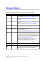
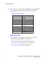
Revision History
This revision history summarizes the changes made in each published version of this document.
Document No.
Publication Date
Description of Revisions
64-0259-06
September 2011
Updated to support Version 6.0 SU8 Software.
Added note for ROLMPhone 400 to PBX Requirements - DMG1000 Models table.
64-0259-05
February 2009
Added new requirement NTU, CSU, DSU, or some other similar device is required
that provides line isolation to Additional Components section in System
Requirements.
64-0259-04
March 2008
Updated to support Version 6.0 Software.
Added new DMG2060DTISQ and DMG2120DTISQ models which include support for
survivability.
Added Rack Mounting Warnings to Installation Procedure - DMG2000 Models.
64-0259-03
January 2008
Updated to support Version 5.1 SU3 Software.
Added new model NEC NEAX 2000 IVS2 to PBX Requirements - DMG1000 Models
table.
64-0259-02
September 2007
Updated to support Version 5.1 SU2 Software.
Added new DMG1004LS model.
Added note to say H.323 is only supported in Version 5.1 SU1 Software or earlier.
Added new model Tenovis Integral 3 to PBX Requirements - E1 QSIG Protocol table.
64-0259-01
March 2007
Updated to support Version 5.1 SU1 Software.
Global Updates: Changed product names and links from Intel to Dialogic.
The document number and title have been updated with new naming conventions.
The products previously known as Intel NetStructure PBX-IP Media Gateway (PIMG)
and T1/E1-IP Media Gateway (TIMG) are now Dialogic® 1000 Media Gateway
(DMG1000) and Dialogic® 2000 Media Gateway (DMG2000). For more product
name changes, refer to New Product Naming Conventions.
Added new models Ericsson MD110, Nortel Meridian 1 - Option 11c, Nortel
Communications Server 1000, and Phillips Sopho (iS3030-288) to PBX
Requirements - E1 QSIG Protocol table.
Removed ECMA references in PBX Requirements tables.
Updated notes to say LAN2 is only supported in Version 5.1 SU1 Software or later.
D40122-002
Rev 01
October 2006
D40122-001
Rev 01
March 2006
Updated to support Version 5.1 Software.
Initial version of document to support Version 5.0 Software.
Much of the information contained in this document was previously published in the
PBX-IP Gateway User’s Guide, document number C73213-001 Rev 02.
Dialogic® 1000 and 2000 Media Gateway Series Getting Started Guide
Dialogic Corporation
11
Revision History
12
Dialogic® 1000 and 2000 Media Gateway Series Getting Started Guide
Dialogic Corporation
About This Publication
The following topics provide information about this guide:
• Purpose
• Intended Audience
• How to Use This Publication
• Related Information
Purpose
This document provides information about installing, cabling, and initializing the Dialogic® Media
Gateway prior to performing configuration and operation tasks.
Intended Audience
This information is intended for:
• Distributors
• System Integrators
• Value Added Resellers (VARs)
• Original Equipment Manufacturers (OEMs)
How to Use This Publication
This information is organized as follows:
• Chapter 1, “Controls, Indicators, and Connectors” describes the front and rear panel controls,
indicators, and connectors for both the Dialogic® 1000 Media Gateway (DMG1000) and
Dialogic® 2000 Media Gateway (DMG2000) models.
• Chapter 2, “Preparing for Installation - DMG1000 Models” provides information about
preparing to install the Dialogic® 1000 Media Gateway (DMG1000) models.
• Chapter 3, “Preparing for Installation - DMG2000 Models” provides information about
preparing to install the Dialogic® 2000 Media Gateway (DMG2000) models.
• Chapter 4, “Installation” provides information about installing and initially logging on to the
Dialogic® 1000 Media Gateway (DMG1000) and Dialogic® 2000 Media Gateway (DMG2000)
models.
Dialogic® 1000 and 2000 Media Gateway Series Getting Started Guide
Dialogic Corporation
13
About This Publication
Note:
The products previously known as Intel NetStructure PBX-IP Media Gateway and T1/E1-IP Media
Gateway are now Dialogic® 1000 Media Gateway (DMG1000) and Dialogic® 2000 Media
Gateway (DMG2000). For more product name changes, refer to New Product Naming
Conventions.
New Product Naming Conventions
Previous Name
PBX-IP Media Gateway
New Name
Dialogic®
1000 Media Gateway
(DMG1000)
PIMG
DMG1000
PIMG40LS
DMG1004LSW
PIMG80LS
DMG1008LSW
PIMG80DNI
DMG1008DNIW
PIMG80MTLDNI
DMG1008MTLDNIW
PIMG80RLMDNI
DMG1008RLMDNIW
T1/E1-IP Media Gateway
Dialogic® 2000 Media Gateway
(DMG2000)
TIMG
DMG2000
TIMG300DTI
DMG2030DTIQ
TIMG600DTI
DMG2060DTIQ
TIMG1200DTI
DMG2120DTIQ
DMG2060DTISQ (with survivability)
DMG2120DTISQ (with survivability)
Related Information
For additional information related to the Dialogic® 1000 Media Gateway (DMG1000) and
Dialogic® 2000 Media Gateway (DMG2000) products, see the following:
• Dialogic® 1000 and 2000 Media Gateway Series User’s Guide
• Dialogic® Media Gateway Installation and Configuration Integration Notes
• High Density Dialogic® Media Gateway Chassis Hardware Installation Guide
• http://www.dialogic.com/manuals/ (for Dialogic® product documentation)
• http://www.dialogic.com/support/ (for Dialogic technical support)
• http://www.dialogic.com/ (for Dialogic® product information)
14
Dialogic® 1000 and 2000 Media Gateway Series Getting Started Guide
Dialogic Corporation
1
Controls, Indicators, and
Connectors
This chapter provides information about the controls, indicators, and connectors for both the
Dialogic® 1000 Media Gateway (DMG1000) and Dialogic® 2000 Media Gateway (DMG2000)
models in the following sections:
• Front Panel Indicators for DMG1000 Models. . . . . . . . . . . . . . . . . . . . . . . . . . . . . . . . 15
• Rear Panel Controls, Indicators, and Connectors for DMG1000 Models . . . . . . . . . . . 17
• Front Panel Indicators for DMG2000 Models. . . . . . . . . . . . . . . . . . . . . . . . . . . . . . . . 19
• Rear Panel Controls, Indicators, and Connectors for DMG2000 Models . . . . . . . . . . . 21
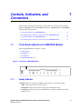
1.1
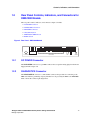
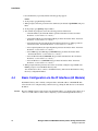
Front Panel Indicators for DMG1000 Models
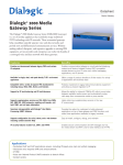
The front panel LED indicators, Figure 1, include:
1. Ready Indicator
2. Link Indicator
3. Data Indicator
4. PORT STATUS Indicators
Figure 1. Front Panel - DMG1000 Models
Ready
Link
1
2
3
PORT STATUS
4
5
6
7
8
Data
1.1.1
Ready Indicator
The Ready indicator is a multicolored LED that shows the unit’s system status, where:
• Unlit - indicates that the unit is not powered on.
• Steady Red - indicates that the unit is in the power-on initialization stage.
• Steady Green - indicates that power-on initialization is complete and the unit is awaiting
application load.
Dialogic® 1000 and 2000 Media Gateway Series Getting Started Guide
Dialogic Corporation
15
Controls, Indicators, and Connectors
• Flashing Green - indicates that the application initialization process has completed and that
the unit is active.
• Flashing Red - indicates that an error has occurred during application initialization. The unit
is inactive.
Note: The cause of the error can be found by checking the DMG1000 Status/Alarm Web
page. See the “Unit Status” chapter in the User’s Guide for details.
• Flashing Orange - indicates that the unit is functional, but it encountered and recovered from
a functional error.
Note: The cause of the error can be found by checking the DMG1000 Status/Alarm Web
page, provided the Ethernet link is up. See the “Unit Status” chapter in the User’s
Guide for details.
1.1.2
Link Indicator
The Link indicator shows the unit’s Ethernet status, where:
• Steady Green - indicates that an Ethernet link has been established.
• Unlit - indicates that no Ethernet link has been established.
1.1.3
Data Indicator
The Data indicator shows the unit’s Ethernet real time processing (RTP) activity, where:
• Flashing Green - indicates that one or more calls are active and that the unit is transmitting
and receiving RTP information.
• Unlit - indicates that the unit is not transmitting or receiving RTP information.
1.1.4
PORT STATUS Indicators
The PORT STATUS indicators (1 through 8) are multicolored LEDs that show the unit’s PBX
Port link status for the respective port. The functions of the PORT STATUS Indicators depend on
whether the DMG1000 is an Emulator or Driver type.
1.1.4.1
Phone Emulating Models (DMG1004LSW, DMG1008LSW,
DMG1008DNIW, DMG1008MTLDNIW, DMG1008RLMDNIW)
When the DMG1000 is a Phone Emulating model, the functions of the PORT STATUS Indicators
are:
• Steady Green - indicates that Carrier is present.
• Flashing Green - indicates that there is activity on the port.
• Steady Yellow - Hardware Carrier is present, but no software communication.
• Flashing Yellow - External power detected, but port cannot gain carrier.
• Steady Red - indicates that no Carrier is present and no external power detected.
16
Dialogic® 1000 and 2000 Media Gateway Series Getting Started Guide
Dialogic Corporation
Controls, Indicators, and Connectors
1.2
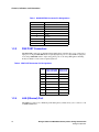
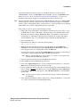
Rear Panel Controls, Indicators, and Connectors for
DMG1000 Models
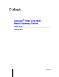
The rear panel controls, indicators, and connectors, Figure 2, include:
• DC POWER Connector
• DIAGNOSTICS Connector
• PBX PORT Connectors
• LAN (Ethernet) Port
• TX/RX/FULL/100 Indicators
• RESET Switch
Figure 2. Rear Panel - DMG1000 Models
TX
RX
FULL
100
1
DC POWER
1.2.1
2
3
DIAGNOSTICS
4
5
6
PBX PORTS
7
8
LAN
RESET
DC POWER Connector
The DC POWER connector is a 5-pin DIN connector that accepts the mating plug from the Power
Supply Unit DC output cord.
1.2.2
DIAGNOSTICS Connector
The DIAGNOSTICS connector is a female DB-9 connector that provides for connecting to the
PBX serial interface, permitting call party information to be passed by the PBX to the DMG1000.
Table 1 shows the connector pin designations.
Dialogic® 1000 and 2000 Media Gateway Series Getting Started Guide
Dialogic Corporation
17
Controls, Indicators, and Connectors
Table 1. DIAGNOSTICS Connector Pin Designations
Pin
1.2.3
Description
1
Not used
2
Transmit
3
Receive
4
Not used
5
Ground
6
Not used
7
Not used
8
Not used
9
Not used
PBX PORT Connectors
The PBX PORT connectors are shielded 8-pin modular phone jacks that allow you to connect up to
eight ports of a digital DMG1000 model to eight digital phone ports on a digital PBX or eight ports
of an analog DMG1000 model to eight analog phone ports on an analog PBX (phone emulating
mode). See Table 2 for the connector pin designations.
Table 2. PBX PORT Connector Pin Designations
DMG1008DNIW,
DMG1008MTLDNIW,
DMG1008RLMDNIW
DMG1004LSW
DMG1008LSW
4
Tip
Tip
5
Ring
Ring
Pin
1
2
3
6
7
8
1.2.4
LAN (Ethernet) Port
The LAN port connector is a shielded 8-pin modular phone jack that allows you to connect to a 10
or 100 BaseT Ethernet.
18
Dialogic® 1000 and 2000 Media Gateway Series Getting Started Guide
Dialogic Corporation
Controls, Indicators, and Connectors
1.2.5
TX/RX/FULL/100 Indicators
The LED indicators on the rear panel provide the following information:
• The TX indicator blinks when data is transmitted across the Ethernet interface.
• The RX indicator blinks when data is received on the Ethernet interface (even data that is not
intended for the DMG1000).
• The FULL indicator lights to show that the Ethernet is connected to the network in full duplex
mode.
• The 100 indicator lights to show that the Ethernet interface is connected to the network at 100
Mbps.
1.2.6
RESET Switch
The RESET switch allows you to restart the DMG1000 Unit. Restarting is necessary to cause
changes to specific parameters to take effect.
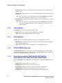
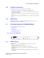
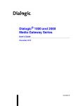
1.3
Front Panel Indicators for DMG2000 Models
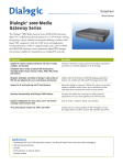
The front panel LED indicators, Figure 3, include:
1. READY Indicator
2. DATA Indicator
3. LAN STATUS 1 and 2 Indicators
4. T1/E1 STATUS Indicators
Figure 3. Front Panel - DMG2000 Models
LAN STATUS
T1/E1 STATUS
1
READY
1
DATA
1.3.1
2
2
3
4
ALARM
LINK
READY Indicator
The READY indicator is a multicolored LED that shows the unit’s system status, where:
• Unlit - indicates that the unit is not powered on.
• Steady Red - indicates that the unit is in the power-on initialization stage.
• Steady Green - indicates that power-on initialization is complete and the unit is awaiting
application load.
• Flashing Green - indicates that the application initialization process has completed and that
the unit is active.
Dialogic® 1000 and 2000 Media Gateway Series Getting Started Guide
Dialogic Corporation
19
Controls, Indicators, and Connectors
• Flashing Red - indicates that an error has occurred during application initialization. The unit
is inactive.
Note: The cause of the error can be found by checking the DMG2000 Status/Alarm Web
page. See the “Unit Status” chapter in the User’s Guide for details.
• Flashing Orange - indicates that the unit is functional, but it encountered and recovered from
a functional error.
Note: The cause of the error can be found by checking the DMG2000 Status/Alarm Web
page, provided the Ethernet link is up. See the “Unit Status” chapter in the User’s
Guide for details.
1.3.2
DATA Indicator
The DATA indicator shows the unit’s Ethernet real time processing (RTP) activity, where:
• Flashing Green - indicates that one or more calls are active and that the unit is transmitting
and receiving RTP information.
• Unlit - indicates that the unit is not transmitting or receiving RTP information.
1.3.3
LAN STATUS 1 and 2 Indicators
The LAN STATUS indicator shows the unit’s Ethernet status, where:
• Steady Green - indicates that an Ethernet link has been established.
• Unlit - indicates that no Ethernet link has been established.
1.3.4
T1/E1 STATUS Indicators
The T1/E1 STATUS indicators are multicolored LEDs that show the unit’s PBX T1/E1 link status
for the respective T1 or E1 port. The T1/E1 STATUS indicators include ALARM and LINK status
indicators.
ALARM Status Indicator
The functions of the ALARM Status Indicators are:
• Unlit - indicates no alarm.
• Steady Red - indicates that local end of T1 or E1 connections is in Red alarm condition.
• Steady Orange - indicates that remote end of T1 or E1 connection is in Red alarm condition.
• Slow Flashing Orange - indicates absence of incoming signal (also know as Blue alarm
condition).
LINK Status Indicator
The functions of the LINK Status Indicators are:
• Unlit - Not used.
20
Dialogic® 1000 and 2000 Media Gateway Series Getting Started Guide
Dialogic Corporation
Controls, Indicators, and Connectors
• Fast Flashing Green - indicates that there is activity on the port.
• Steady Orange - indicates that frame is in sync.
• Medium Flashing Between Green and Orange - indicates that frame is in sync and waiting
for ISDN D-channel to come up.
• Steady Green - indicates that operational layer is in sync.
• Steady Red - indicates that no carrier is present.
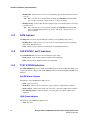
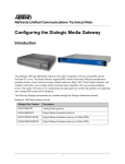
1.4
Rear Panel Controls, Indicators, and Connectors for
DMG2000 Models
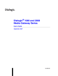
The rear panel controls, indicators, and connectors, Figure 4, include:
• AC Power Connector
• AC Power Switch
• T1/E1 Connectors
• COM 1 and COM 2 Connectors
• LAN1 and LAN2 (Ethernet) Port
Figure 4. Rear Panel - DMG2000 Models
LAN
T1/E1
4
3
2
1
COM 1
2
1
COM 2
1.4.1
AC Power Connector
The AC Power Connector supports either the 115 VAC commonly used in NA or the 220 VAC
commonly used in EU. See Section 3.2.2, “AC Power Cord”, on page 28 for details regarding the
power cord shipped with the unit
1.4.2
AC Power Switch
The AC power switch is a two position rocker switch that, when in the on (I) position, applies
power to the unit.
1.4.3
T1/E1 Connectors
The T1/E1 connectors are RJ-45 connectors that provide connections to T1 or E1 trunks. See
Table 3 for the connector pin designations.
Dialogic® 1000 and 2000 Media Gateway Series Getting Started Guide
Dialogic Corporation
21
Controls, Indicators, and Connectors
Table 3. T1/E1 Connector Pin Designations
Pin
1.4.4
Description
1
RCV_RING
2
RCV_TIP
3
No connection
4
XMIT_RING
5
XMIT_TIP
6
No connection
7
No connection
8
No connection
COM 1 and COM 2 Connectors
COM 1 and COM 2 are DB9 serial port connectors. The COM 1 port is used for interfacing to PBX
Serial Integration Protocols. The COM 2 port is used for interfacing to a diagnostics/administration
terminal. Refer to the User’s Guide for configuration information. See Table 4 for the connector
pin designations.
Table 4. COM 1 and COM 2 Connector Pin Designations
Pin
1.4.5
Signal
1
Data Carrier Detect
2
Transmit Data
3
Receive Data
4
Data Terminal Ready
5
Signal Ground
6
Data Set Ready
7
Clear to Send
8
Request to Send
9
Ring Indicator
LAN1 and LAN2 (Ethernet) Port
The LAN1 connector is a shielded 8-pin modular phone jack that allows you to connect to a 10/100
BaseT Ethernet. This interface can be used to connect to the unit to VoIP endpoints and to connect
users to the units maintenance interface. The LAN2 connector is a shielded 8-pin modular phone
jack that allows you to connect to a 10/100 BaseT Ethernet. This interface can be used to connect
users to the units maintenance interface.
Note:
22
Currently, the LAN2 connector is only supported in Version 5.1 SU1 Software or later.
Dialogic® 1000 and 2000 Media Gateway Series Getting Started Guide
Dialogic Corporation
Preparing for Installation DMG1000 Models
2
This chapter provides information about preparing to install the Dialogic® 1000 Media Gateway
(DMG1000) models in the following sections:
• Unpacking the Unit . . . . . . . . . . . . . . . . . . . . . . . . . . . . . . . . . . . . . . . . . . . . . . . . . . . . 23
• Components of the System . . . . . . . . . . . . . . . . . . . . . . . . . . . . . . . . . . . . . . . . . . . . . . 23
• System Requirements . . . . . . . . . . . . . . . . . . . . . . . . . . . . . . . . . . . . . . . . . . . . . . . . . . 25
2.1
Unpacking the Unit
The DMG1000, as shipped, consists of the following items:
• DMG1000 Unit
• Power Supply Unit
• AC Power Cord
• Getting Started Guide
• Regulatory Notice
• China DOC (Declaration of Conformity)
Before proceeding, be sure the DMG1000 you have received includes all of these items.
2.2
Components of the System
The DMG1000 system includes the following components:
• DMG1000 Unit
• Power Supply Unit
• AC Power Cord
Dialogic® 1000 and 2000 Media Gateway Series Getting Started Guide
Dialogic Corporation
23
Preparing for Installation - DMG1000 Models
2.2.1
DMG1000 Unit
The DMG1000 unit is the main component of the system. This device accepts up to eight digital
voice connections from the PBX. The unit translates each digital voice channel into H.323 or SIP
format and connects these channels to devices on an IP-based LAN.
Note:
2.2.2
H.323 is only supported in Version 5.1 SU1 Software or earlier.
Power Supply Unit
The Power Supply Unit is an AC to DC converter that connects via the AC Power Cord to an AC
source. The unit contains a DC cord that terminates in a 5-pin DIN connector. This cord connects
to the DC POWER connector on the rear panel of the DMG1000.
2.2.3
AC Power Cord
The AC Power Cord connects the Power Supply Unit to an AC power source.
Warning!
Do not attempt to modify or use the supplied AC power cord if it is not the exact type
required.
Avertissement!
Ne pas utiliser ni midifier le cable d.alimentation C.A. fourni, s.il ne correspond pas
exactement au type requis.
Warnug!
Versuchen Sie nicht, das mitgelieferte Netzkabel zu ändern oder zu verwenden, wenn es
sich nicht um genau den erforderlichen Typ handelt.
Avvertenza!
Non modificare o utilizzare il cavo di alimentazione in c.a. fornito dal produttore, se non
corrisponde esattamente al tipo richiesto.
¡Advertencias!
No intente modifcar ni usar el cable de alimentación de corriente alterna, si no se
corresponde exactamente con el tip requerido.
24
Dialogic® 1000 and 2000 Media Gateway Series Getting Started Guide
Dialogic Corporation
Preparing for Installation - DMG1000 Models
In some cases, the power cord supplied with this system may not be compatible with the AC wall
outlet in your region. If this is true, you must obtain a suitable power cord that meets the following
criteria:
• The cord must be rated for use at the AC voltage available, with a current rating that is at least
125% of the current rating of the product (for current rating information, refer to the UL label
affixed to the power supply).
• The AC plug end must be terminated in a grounding-type male plug designed for use in your
region. The plug ends must be labeled or marked to indicate they have been certified by an
agency acceptable in your region.
• The power service must be connected through a properly grounded outlet.
• The connector at the product end must be an IEC 320, sheet C13, female connector (or the
equivalent EN 60 320 connector).
• The cord must be less than 14.8 feet (4.5 meters) long and, for use in Europe, be created with
<HAR> (harmonized) or VDE certified cordage.
If power needs to be removed from this product, you must disconnect the power cord; therefore, the
socket-outlet shall be installed near the equipment and shall be easily accessible.
2.3
System Requirements
System requirements include the following:
• Additional Components
• Power Requirements
• PBX Requirements
2.3.1
Additional Components
Additional components that are not supplied with the product, but are necessary to complete the
installation, include:
• PBX port to DMG1000 port cable (one per port) - Phone Emulating models
• 10/100 BaseT Ethernet cable
2.3.2
Power Requirements
The power requirements of the Power Supply Unit are:
• Line Voltage:90 to 264 Volts AC
• Frequency:47 to 63 Hz
Dialogic® 1000 and 2000 Media Gateway Series Getting Started Guide
Dialogic Corporation
25
Preparing for Installation - DMG1000 Models
2.3.3
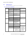
PBX Requirements
Table 5 lists the requirements for each of the PBX types supported by the DMG1000 unit.
Table 5. PBX Requirements - DMG1000 Models
Manufacturer
Avaya
Models
Software Version
DEFINITY G3
Version 3 or greater
S8100, S8300, S8700,
S8710
Communications Manager Software
Version 2.0 or greater
Magix
Release 2.0 or greater
4424D
Mitel
SX-200D, SX-200 Light,
SX-2000 Light, SX-2000 S,
SX-2000 VS
Lightware Release 17 or greater
Superset 430
Nortel
Meridian 1-Option 11, 21,
21A, 51, 61, 71, and 81
Release 15 or greater and options
19 and 46 are required
M2616
Meridian SL1-Generic X11
Release 15 or greater, and options
19 and 46 are required
Nortel Communications
Server - 1000M, 1000S, and
1000E
Release V3.0 or greater
Norstar 8x24
DR5 Release 1.2 or greater
Norstar MICS
Release 4.5 or greater
2400 IMG
Release 7400 or greater
2400 IMX
Release 5200 Dec. 92 1b or greater
2400IPX
Release V.17 Issue 3.46.001
NEAX 2000 IVS2
SC#: SC-3385
OFFICIAL ISSUE: K1-0003.05
ENG ISSUE: FF-0012.00
DATE: 2003/08/03
Hicom 300E CS
Release 9006.4 or greater (North
American software load only)
Hicom 300E
Release 2.0 or greater (EU software
load only)
8000
Release 80003 or greater
ROLMPhone 400
9000
Any release
9751
Any release of 9005
Note: Audio quality may
decrease if connecting
less than 8 lines to the
DMG1008RLMDNI.
Workarounds include
disabling ports through
the Web interface or
connecting 8 active
lines to the
DMG1008RLMDNI.
NEC
Siemens
9751
Release 9006.3 or greater
Note: Release 9006.4 or greater
required to support end-toend signalling necessary with
many Media Server
applications (e.g. Voice Mail,
Unified Messaging, IVR, etc.)
26
Digital Station Set
8434DX or 7434ND (2-wire
models)
M7324
DTerm III
E Advance Plus
Dialogic® 1000 and 2000 Media Gateway Series Getting Started Guide
Dialogic Corporation
Preparing for Installation DMG2000 Models
3
This chapter provides information about preparing to install the Dialogic® 2000 Media Gateway
(DMG2000) models in the following sections:
• Unpacking the Unit . . . . . . . . . . . . . . . . . . . . . . . . . . . . . . . . . . . . . . . . . . . . . . . . . . . . 27
• Components of the System . . . . . . . . . . . . . . . . . . . . . . . . . . . . . . . . . . . . . . . . . . . . . . 27
• System Requirements . . . . . . . . . . . . . . . . . . . . . . . . . . . . . . . . . . . . . . . . . . . . . . . . . . 29
3.1
Unpacking the Unit
The DMG2000, as shipped, consists of the following items:
• DMG2000 Unit
• AC Power Cord
• Getting Started Guide
• Regulatory Notice
• China DOC (Declaration of Conformity)
Before proceeding, be sure the DMG2000 you have received includes all of these items.
3.2
Components of the System
The DMG2000 system includes the following components:
• DMG2000 Unit
• AC Power Cord
Dialogic® 1000 and 2000 Media Gateway Series Getting Started Guide
Dialogic Corporation
27
Preparing for Installation - DMG2000 Models
3.2.1
DMG2000 Unit
The DMG2000 unit is the main component of the system. This device accepts one
(DMG2030DTIQ), two (DMG2060DTIQ / DMG2060DTISQ), or four T1/E1 (DMG2120DTIQ /
DMG2120DTISQ) connections from the PBX. The unit translates each digital voice channel of a
T1 or E1 trunk into H.323 or SIP format and connects these channels to devices on an IP-based
LAN.
Note:
3.2.2
H.323 is only supported in Version 5.1 SU1 Software or earlier.
AC Power Cord
The AC Power Cord connects the Power Supply Unit to a 115 VAC power source.
Warning!
Do not attempt to modify or use the supplied AC power cord if it is not the exact type
required.
Avertissement!
Ne pas utiliser ni modifier le cable d’alimentation secteur fourni, s’il ne correspond pas
exactement au type requis.
Warnug!
Versuchen Sie nicht, das mitgelieferte Netzkabel zu ändern oder zu verwenden, wenn es
sich nicht um genau den erforderlichen Typ handelt.
Avvertenza!
Non modificare o utilizzare il cavo di alimentazione in c.a. fornito dal produttore, se non
corrisponde esattamente al tipo richiesto.
¡Advertencias!
No intente modifcar ni usar el cable de alimentación de corriente alterna, si no se
corresponde exactamente con el tip requerido.
28
Dialogic® 1000 and 2000 Media Gateway Series Getting Started Guide
Dialogic Corporation
Preparing for Installation - DMG2000 Models
In some cases, the power cord supplied with this system may not be compatible with the AC wall
outlet in your region. If this is true, you must obtain a suitable power cord that meets the following
criteria:
• The cord must be rated for use at the AC voltage available, with a current rating that is at least
125% of the current rating of the product (for current rating information, refer to the UL label
affixed to the power supply).
• The AC plug end must be terminated in a grounding-type male plug designed for use in your
region. The plug ends must be labeled or marked to indicate they have been certified by an
agency acceptable in your region.
• The power service must be connected through a properly grounded outlet.
• The connector at the product end must be an IEC 320, sheet C13, female connector (or the
equivalent EN 60 320 connector).
• The cord must be less than 14.8 feet (4.5 meters) long and, for use in Europe, be created with
<HAR> (harmonized) or VDE certified cordage.
If power needs to be removed from this product, you must disconnect the power cord; therefore, the
socket-outlet shall be installed near the equipment and shall be easily accessible.
3.3
System Requirements
System requirements include the following:
• Additional Components
• Power Requirements
• Protocols Supported/PBXs Validated Against
3.3.1
Additional Components
Additional components that are not supplied with the product, but are necessary to complete the
installation, include:
• PBX port to DMG2000 port T1 or E1 cable (one per span)
• 10/100 BaseT Ethernet cable
• NTU, CSU, DSU, or some other similar device is required that provides line isolation
Note: This device is required only if the product is not connecting directly to a PBX T1 or
E1 interface. Please refer to Safety Warnings section of Regulatory Notice included
with the product.
3.3.2
Power Requirements
The power requirements of the DMG2000 unit are:
• Line Voltage:90 to 264 Volts AC
• Frequency:47 to 63 Hz
Dialogic® 1000 and 2000 Media Gateway Series Getting Started Guide
Dialogic Corporation
29
Preparing for Installation - DMG2000 Models
3.3.3
Protocols Supported/PBXs Validated Against
The DMG2000 supports the following protocols and has been validated against the PBXs listed in
the respective tables:
• T1 CAS (see Table 6)
• T1 QSIG (see Table 7)
• T1 NI-2 (see Table 8)
• E1 QSIG (see Table 9)
• T1 5ESS (see Table 10)
• T1 DMS100 (see Table 11)
• E1 ETSI (EuroISDN)
Note:
The following supplemental services must be supported by the PBXs listed in the following tables
in order for the DMG2000 to provide the features required by VoIP Messaging Applications (e.g.
Unified Messaging, Voice Mail, etc.)
• Call Transfer
• Diversion
• MWI (Optional)
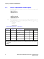
Table 6. PBX Requirements - T1 CAS Protocol
Manufacturer
Models
Software Version
Supplemental Service Support
Call Party ID
Transfer
MWI
Avaya
DEFINITY G3
Version 3 or greater
✔
✔
✔
Avaya
S8500
Communications Manager SW
V2.0 or greater
✔
✔
✔
Nortel
Meridian 1- Option
11c
Release 15 or greater, and
options 19 and 46 are required
—
—
—
NEC
2400 IMX
Release 5200 Dec. 92 1b or
greater
✔1
✔
✔1
Siemens
Hicom 300E CS
Release 9006.4 or greater
✔2
✔
✔
(North American Software load
only.
Note 1: Call Party ID and MWI are supported via the MCI serial protocol.
Note 2: PBX does not send the Calling Party on inbound calls. However, the Called Party and the Call Reason Code fields
are supported.
✔ = Supported
— = Not Supported by the DMG2000 and/or the PBX.
30
Dialogic® 1000 and 2000 Media Gateway Series Getting Started Guide
Dialogic Corporation
Preparing for Installation - DMG2000 Models
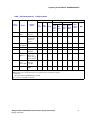
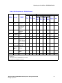
Table 7. PBX Requirements - T1 QSIG Protocol
Basic Call Control
Supplemental Service Support
Diversion
Manufacturer
Models
Software
Version
Inbound
Outbound
CPID
Call Transfer
Forward
ID &
Reason
Redirect
Join
(Hairpin)
ReRoute
(TBCT)
Path
Replace
ment
MWI
Alcatel
Omni PCX
4400
Version
3.2.712.5
✔
✔
✔
✔
—
✔
N/A
✔
✔
Avaya
S8500
Communications Manager
SW V2.0 or
greater
✔
✔
✔
✔
—
✔
N/A
✔
✔
Mitel
SX-2000 S,
SX-2000 VS
LW 34
✔
✔
✔
✔
—
✔
N/A
✔
✔
Mitel
3300
Version 5.1.4.8
✔
✔
✔
✔
—
✔
N/A
✔
✔
NEC
2400 IPX
R17 Release
03.46.001
✔
✔
✔
✔
—
✔
✔
✔
✔1
Nortel
Meridian 1Option 11c
Release 15 or
greater, and
options 19 and
46 are required
✔
✔
✔
✔
—
✔2
N/A
✔
✔
Nortel
Communica
-tions
Server 1000
Version 2121,
Release 4,
Issue 00 T
✔
✔
✔
✔
—
✔2
N/A
✔
✔
Siemens
HiPath 4000
V2 SMR 9
SMPO
✔
✔
✔
✔
—
✔2
N/A
✔
✔
Note 1. MWI operation is supported via the MCI serial protocol.
Note 2. Display on the called party phone does not update after the Join transfer completes.
✔ = Supported
— = Not Supported by the DMG2000 and/or the PBX.
N/A = Feature is not available on this PBX.
Dialogic® 1000 and 2000 Media Gateway Series Getting Started Guide
Dialogic Corporation
31
Preparing for Installation - DMG2000 Models
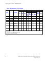
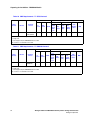
Table 8. PBX Requirements - T1 NI-2 Protocol
Basic Call Control
Supplemental Service Support
Diversion
Manufacturer
Models
Software
Version
Inbound
Outbound
CPID
Call Transfer
Forward
ID &
Reason
Redirect
Join
(Hairpin)
ReRoute
(TBCT)
Path
Replace
ment
MWI
Avaya
5ESS
Version
5e16(2)02.00
✔
✔
✔
✔
—
N/A
✔
N/A
✔1
Mitel
SX-2000 S,
SX-2000 VS
LW 34
✔
✔
✔
N/A
N/A
N/A
N/A
N/A
N/A
Mitel
3300
Version 5.1.4.8
✔
✔
✔
N/A
N/A
N/A
N/A
N/A
N/A
NEC
All Models
N/A
N/A
N/A
N/A
N/A
N/A
N/A
N/A
N/A
N/A
Nortel
DMS100
Version
SN000.007
✔
✔
✔
✔
—
N/A
✔
N/A
✔
Nortel
Meridian 1Option 11c
Release 15 or
greater, and
options 19 and
46 are required
✔
✔
✔
—
—
—
—
—
—
Siemens
HiPath 4000
V2 SMR 9
SMPO
✔
✔
✔
—
—
—
—
—
—
Note 1. MWI operatIon is supported via the SMDI serial protocol.
✔ = Supported
— = Not Supported by the DMG2000 and/or the PBX.
N/A = Feature is not available on this PBX.
32
Dialogic® 1000 and 2000 Media Gateway Series Getting Started Guide
Dialogic Corporation
Preparing for Installation - DMG2000 Models
Table 9. PBX Requirements - E1 QSIG Protocol
Basic Call Control
Supplemental Service Support
Diversion
Manufacturer
Models
Software
Version
Inbound
Outbound
CPID
Call Transfer
Forward
ID &
Reason
Redirect
Join
(Hairpin)
ReRoute
(TBCT)
Path
Replace
ment
MWI
Alcatel
Omni PCX
4400
Version
3.2.712.5
✔
✔
✔
✔
—
✔
N/A
✔
✔
Avaya
S8500
Communications Manager
SW V2.0 or
greater
✔
✔
✔
✔
—
✔
N/A
✔
✔
Ericsson
MD110
Release MX1
TSW R2A
(BC13)
✔
✔
✔
✔
—
✔
N/A
✔
✔
Mitel
SX-2000 S,
SX-2000 VS
LW 34
✔
✔
✔
✔
—
✔
N/A
✔
✔
Mitel
3300
Version 5.1.4.8
✔
✔
✔
✔
—
✔
N/A
✔
✔
N/A
✔
✔
Nortel
Meridian 1 Option 11c
Release 15 or
greater and
options 19 and
46 are required
✔
✔
✔
✔
—
✔1
Nortel
Communica
-tions
Server 1000
Version 2121,
RELEASE 4,
ISSUE 00 T
✔
✔
✔
✔
—
✔1
N/A
✔
✔
Phillips
Sopho
(iS3030288)
Version
6810.34
✔
✔
✔
✔
—
✔
N/A
✔
✔
Siemens
HiPath 4000
V2 SMR 9
SMPO
✔
✔
✔
✔
—
✔1
N/A
✔
✔
Tenovis
Integral 3
E062V01.0.0.2
✔
✔
✔
✔
—
✔
N/A
✔
✔
Note 1. Display on the called party phone does not update after the Join transfer completes.
✔ = Supported
— = Not Supported by the DMG2000 and/or the PBX.
N/A = Feature is not available on this PBX.
Dialogic® 1000 and 2000 Media Gateway Series Getting Started Guide
Dialogic Corporation
33
Preparing for Installation - DMG2000 Models
Table 10. PBX Requirements - T1 5ESS Protocol
Basic Call Control
Supplemental Service Support
Diversion
Manufacturer
Avaya
Models
5ESS
Software
Version
Version
5e16(2)02.00
Inbound
Outbound
CPID
✔
✔
✔
Call Transfer
Forward
ID &
Reason
Redirect
Join
(Hairpin)
ReRoute
(TBCT)
✔
—
N/A
✔
Path
Replace
ment
MWI
N/A
✔1
Note 1. MWI operatIon is supported via the SMDI serial protocol.
✔ = Supported
— = Not Supported by the DMG2000 and/or the PBX.
N/A = Feature is not available on this PBX.
Table 11. PBX Requirements - T1 DMS100 Protocol
Basic Call Control
Supplemental Service Support
Diversion
Manufacturer
Nortel
Models
DMS100
Software
Version
Version
SN000.007
Inbound
Outbound
CPID
✔
✔
✔
Call Transfer
Forward
ID &
Reason
Redirect
Join
(Hairpin)
ReRoute
(TBCT)
✔
—
N/A
✔
Path
Replace
ment
MWI
N/A
✔1
Note 1. MWI operatIon is supported via the SMDI serial protocol.
✔ = Supported
— = Not Supported by the DMG2000 and/or the PBX.
N/A = Feature is not available on this PBX.
34
Dialogic® 1000 and 2000 Media Gateway Series Getting Started Guide
Dialogic Corporation
Installation
4
This chapter provides information about installing and initially logging on to the Dialogic® 1000
Media Gateway (DMG1000) and Dialogic® 2000 Media Gateway (DMG2000) models in the
following sections:
• Installation Procedure - DMG1000 Models . . . . . . . . . . . . . . . . . . . . . . . . . . . . . . . . . 35
• Installation Procedure - DMG2000 Models . . . . . . . . . . . . . . . . . . . . . . . . . . . . . . . . . 36
• Basic Configuration via the Serial Port (All Models) . . . . . . . . . . . . . . . . . . . . . . . . . . 37
• Basic Configuration via the IP Interface (All Models) . . . . . . . . . . . . . . . . . . . . . . . . . 38
4.1
Installation Procedure - DMG1000 Models
Perform the following steps to install the DMG1000 system for use as a phone emulator (connected
to PBX):
1. Connect the 10/100BaseT Ethernet cable from the LAN connector on the rear panel of the
DMG1000 to the Ethernet. See Section 1.2, “Rear Panel Controls, Indicators, and Connectors
for DMG1000 Models”, on page 17 for descriptions of the rear panel connectors.
2. For a digital DMG1000, connect up to eight digital PBX lines from the digital PBX to the
eight PBX Port connectors on the rear panel of the DMG1000. (See the User’s Guide for more
details.)
For an analog DMG1000, connect up to eight analog PBX lines from the analog PBX to the
eight PBX Port connectors on the rear panel of the DMG1000.
To connect a port on the DMG1000 to the associated PBX port, a PBX-to-DMG1000 cable is
needed. This requires an 8-wire cable with an 8-pin modular plug on one end and a connector
on the other end that is determined by the mating connector on the PBX.
The DMG1000 is connected to the PBX as follows:
a. Connect the 8-pin modular plug end of a PBX-to-DMG1000 cable to PBX PORT
connector 1 on the rear panel of the DMG1000.
b. Connect the other end of the PBX-to-DMG1000 cable to a telephone port on the PBX.
c. Repeat steps 1 and 2 for each successive PBX port that is to be connected to the
DMG1000.
Dialogic® 1000 and 2000 Media Gateway Series Getting Started Guide
Dialogic Corporation
35
Installation
3. Connect the 5-pin DIN plug from the Power Supply Unit DC output to the DC POWER
connector on the rear panel of the DMG1000.
CAUTION
Be sure to connect the DC cable from the Power Supply Unit to the DMG1000 before
connecting the AC Power Cord to the AC power source.
4. Connect the AC Power Cord from the Power Supply Unit to an AC power source. This will
immediately apply power to the DMG1000.
5. Observe the initial status of the front panel indicators.
See Section 1.1, “Front Panel Indicators for DMG1000 Models”, on page 15 to interpret the status
of the DMG1000 LEDs during unit initialization.
4.2
Installation Procedure - DMG2000 Models
Perform the following steps to install the DMG2000 model (phone emulator):
1. Mount the unit in a standard 19” rack. The DMG2000 occupies 1 rack unit (RU).
Rack Mounting Warnings:
• If installed in a closed or multi-unit rack assembly, the operating ambient temperature of
the rack environment may be greater than room ambient. Therefore, consideration should
be given to installing the equipment in an environment compatible with the maximum
ambient temperature of 40°C.
• Installation of the equipment in a rack should be such that the amount of air flow required
for safe operation of the equipment is not compromised.
• Mounting of the equipment in the rack should be such that a hazardous condition is not
achieved due to uneven mechanical loading.
• Consideration should be given to the connection of the equipment to the supply circuit
and the effect that overloading of the circuits might have on over current protection and
supply wiring. Appropriate consideration of equipment nameplate ratings should be used
when addressing this concern.
• Reliable earthing of rack-mounted equipment should be maintained. Particular attention
should be given to supply connections other than direct connections to the branch circuit
(e.g. use of power strips).
36
Dialogic® 1000 and 2000 Media Gateway Series Getting Started Guide
Dialogic Corporation
Installation
2. Connect the 10/100BaseT Ethernet cable from the LAN1 connector on the rear panel of the
DMG2000 to the Ethernet. See Section 1.4, “Rear Panel Controls, Indicators, and Connectors
for DMG2000 Models”, on page 21 for descriptions of rear panel connectors.
3. Depending on your model, connect one, two, or four T1 or E1 cables from the PBX to the
T1/E1 connectors on the rear panel of the DMG2000. (See User’s Guide for more details.)
4. Connect the AC Power Cord from the connector on the rear of the DMG2000 to an AC power
source.
5. Turn the power switch to the on (I) position.
6. Observe the initial status of the front panel indicators.
See Section 1.3, “Front Panel Indicators for DMG2000 Models”, on page 19 to interpret the status
of the DMG2000 LEDs during unit initialization.
4.3
Basic Configuration via the Serial Port (All Models)
For first time configuration, the preferred and recommended method for initially logging on and
performing basic configuration of the Media Gateway is via the serial port.
Note:
If configuring the unit via the serial port is not an option, the unit can also be initially configured
via the Web interface - please see Section 4.4, “Basic Configuration via the IP Interface (All
Models)”, on page 38.
Additionally, the serial port can be used to reconfigure the unit when a previously configured IP
address becomes unreachable on your network.
The following procedure can be used to set the Client IP Address, Client Subnet Mask, Default
Network Gateway Address, Operating Mode, and PBX Type parameters of the Media Gateway
unit via the serial port:
1. Connect a serial cable to the serial connector on the rear panel of the Media Gateway unit
(DIAGNOSTICS connector on DMG1000 models and COM 2 connector on DMG2000
models). For connector pin designation information, refer to Table 1, “DIAGNOSTICS
Connector Pin Designations”, on page 18 or Table 4, “COM 1 and COM 2 Connector Pin
Designations”, on page 22.
2. Using a standard serial interface application (for example, Procomm Plus or HyperTerminal),
set the workstation to the following:
• Baud Rate = 38400 (DMG1000 models) or 115200 (DMG2000 models)
• Parity = None
• Data Bits = 8
• Stop Bits = 1
• Hardware Flow Control = Off
Dialogic® 1000 and 2000 Media Gateway Series Getting Started Guide
Dialogic Corporation
37
Installation
3. Press the Enter key repeatedly until the following prompt appears:
PIMG>
4. At the prompt, type pwd and press Enter.
5. When prompted, enter the password for the admin user (the default is IpodAdmin) and press
Enter.
6. At the prompt, type quickcfg and press Enter.
7. You will then be prompted to enter the following parameter information:
• Client IP Address (See Client IP Address parameter information in the “Parameter
Reference” section of the User’s Guide.)
• Client Subnet Mask (See Client Subnet Mask parameter information in the “Parameter
Reference” section of the User’s Guide.)
• Network Gateway IP (if required) (See Default Network Gateway Address parameter
information in the “Parameter Reference” section of the User’s Guide.)
• Select Operating Mode (See Operating Mode parameter information in the “Parameter
Reference” section of the User’s Guide.)
• Select PBX Type (See PBX Type (DMG1000 Only) parameter information in the
“Parameter Reference” section of the User’s Guide.)
• Select T1/E1 Line Mode (DMG2000 only) parameter information in the “Parameter
Reference” section of the User’s Guide.)
• Select T1/E1 Protocol (DMG2000 only) parameter information in the “Parameter
Reference” section of the User’s Guide.)
8. When prompted that the parameters have been successfully configured, type restart at the
PIMG> prompt to restart the Media Gateway unit.
You should now be able to connect to the Media Gateway unit from the Web interface using
the newly configured IP Address.
4.4
Basic Configuration via the IP Interface (All Models)
Each Media Gateway unit is initially configured with a default IP address of 10.12.13.74. This
allows the unit to be configured using a Web browser by pointing the Web browser to the default
IP address.
Caution:
38
Because all Media Gateway units use the same default IP address, you should connect them one at
a time to avoid IP address conflicts when configuring a system with multiple Media Gateways.
Dialogic® 1000 and 2000 Media Gateway Series Getting Started Guide
Dialogic Corporation
Installation
The preferred method for initially logging on to the Media Gateway is via the serial port
(DIAGNOSTICS connector on DMG1000 models and COM 2 connector on DMG2000 models).
Refer to Section 4.3, “Basic Configuration via the Serial Port (All Models)”, on page 37 for
information about initially logging on to the Media Gateway unit via the serial port.
Note:
The unit’s IP address must be changed from the default IP address in order to have multiple Media
Gateway units in a system. If you do not use the serial port for initially logging on to the Media
Gateway, refer to “Setting the IP Address” section in the User’s Guide for instructions on changing
the IP address once you have completed the initial log on procedure.
If the serial port is not an option, use the following procedure.
1. Temporarily change the IP address of the Windows® workstation that you are using to access
the Media Gateway unit to an IP address on the same subnet as the default IP address of the
Media Gateway unit (For example, 10.12.13.75). Refer to the Windows® workstation user
documentation or online Help for information about changing the workstation IP address.
You should then be able to access the Media Gateway unit using its default IP address.
2. Start your Web browser.
3. In the Web browser address box, enter the following address:
http://10.12.13.74
4. When the System Login dialog box appears, enter the default user name admin in the
Username box and enter the default password IpodAdmin in the Password box (the user
name and password are case-sensitive) then click on the OK button.
Once the login has been accepted, the initial DMG1000 Web page will appear. At this time you
are required to configure the Operating Mode and PBX Type parameters.
Note: Refer to “Parameter Reference” chapter in the User’s Guide for a description of the
Operating Mode and PBX Type parameters.
5. Select an operating mode from the Operating Mode drop down list.
6. Select a PBX type from the PBX Type drop down list.
7. Click on the Apply Changes button to save the configuration in the database, or click on the
Reset button to return the parameter to the previous value.
8. For the configuration change to take effect, you will be prompted to restart the Media Gateway
unit by clicking on Restart on the Web page or by selecting Restart from the Configuration
menu. When the Restart Web page appears, click on Restart Unit Now to restart the Media
Gateway unit.
Note: You do not need to perform a restart at this time, but may continue with setting the
new IP address.
9. After completing the Initial Log On procedure, refer to “Setting the IP Address” section in the
User’s Guide for instructions on changing the IP address.
Dialogic® 1000 and 2000 Media Gateway Series Getting Started Guide
Dialogic Corporation
39
Installation
40
Dialogic® 1000 and 2000 Media Gateway Series Getting Started Guide
Dialogic Corporation