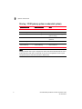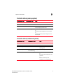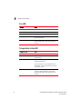
1
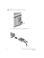
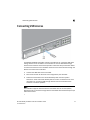
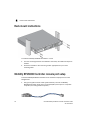
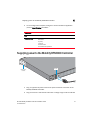
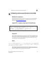
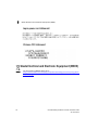
® Brocade Mobility RFS6000 Controller Installation Guide 53-1001573-03 Rev B Copyright © 2009 - 2011 Brocade Communications Systems, Inc. All Rights Reserved. Brocade, the B-wing symbol, BigIron, DCX, Fabric OS, FastIron, IronPoint, IronShield, IronView, IronWare, JetCore, NetIron, SecureIron, ServerIron, StorageX, and TurboIron are registered trademarks, and DCFM, Extraordinary Networks, and SAN Health are trademarks of Brocade Communications Systems, Inc., in the United States and/or in other countries. All other brands, products, or service names are or may be trademarks or service marks of, and are used to identify, products or services of their respective owners. Notice: This document is for informational purposes only and does not set forth any warranty, expressed or implied, concerning any equipment, equipment feature, or service offered or to be offered by Brocade. Brocade reserves the right to make changes to this document at any time, without notice, and assumes no responsibility for its use. This informational document describes features that may not be currently available. Contact a Brocade sales office for information on feature and product availability. Export of technical data contained in this document may require an export license from the United States government. The authors and Brocade Communications Systems, Inc. shall have no liability or responsibility to any person or entity with respect to any loss, cost, liability, or damages arising from the information contained in this book or the computer programs that accompany it. Brocade Communications Systems, Incorporated Corporate and Latin American Headquarters Brocade Communications Systems, Inc. 130 Holger Way San Jose, CA 95134 Tel: 1-408-333-8000 Fax: 1-408-333-8101 E-mail: [email protected] Asia-Pacific Headquarters Brocade Communications Systems China HK, Ltd. No. 1 Guanghua Road Chao Yang District Units 2718 and 2818 Beijing 100020, China Tel: +8610 6588 8888 Fax: +8610 6588 9999 E-mail: [email protected] European Headquarters Brocade Communications Switzerland Sàrl Centre Swissair Tour B - 4ème étage 29, Route de l'Aéroport Case Postale 105 CH-1215 Genève 15 Switzerland Tel: +41 22 799 5640 Fax: +41 22 799 5641 E-mail: [email protected] Asia-Pacific Headquarters Brocade Communications Systems Co., Ltd. (Shenzhen WFOE) Citic Plaza No. 233 Tian He Road North Unit 1308 – 13th Floor Guangzhou, China Tel: +8620 3891 2000 Fax: +8620 3891 2111 E-mail: [email protected] Document History Title Publication number Summary of changes Date Brocade Mobility RFS6000 Controller Installation Guide 53-1001573-03 Updated WEEE icon and Korea Class A statement May 2011 Brocade Mobility RFS6000 Controller Installation Guide 53-1001573-02 Updated company addrress Jan 2011 Brocade Mobility RFS6000 Controller Installation Guide 53-1001573-01 New document Dec 2009 1 Introduction 1 Package contents . . . . . . . . . . . . . . . . . . . . . . . . . . . . . . . . . . . . . . . . . . . . . . . . . . . . .1 Warnings . . . . . . . . . . . . . . . . . . . . . . . . . . . . . . . . . . . . . . . . . . . . . . . . . . . . . . . . . . . .2 Site preparation . . . . . . . . . . . . . . . . . . . . . . . . . . . . . . . . . . . . . . . . . . . . . . . . . . . . . .3 2 Specifications 5 Physical specifications . . . . . . . . . . . . . . . . . . . . . . . . . . . . . . . . . . . . . . . . . . . . . . . . .5 Power cord specifications . . . . . . . . . . . . . . . . . . . . . . . . . . . . . . . . . . . . . . . . . . . . . .5 Power protection . . . . . . . . . . . . . . . . . . . . . . . . . . . . . . . . . . . . . . . . . . . . . . . . . . . . . . . . . . . 5 3 LED Codes 7 System status LEDs . . . . . . . . . . . . . . . . . . . . . . . . . . . . . . . . . . . . . . . . . . . . . . . . . . .7 Start up / POST (primary system or redundant system) . . . . . . . . . . . . . . . . . . . . . . . . . . . . Controller status (primary system) . . . . . . . . . . . . . . . . . . . . . . . . . . . . . . . . . . . . . . . . . . . . . Controller status (redundant system) . . . . . . . . . . . . . . . . . . . . . . . . . . . . . . . . . . . . . . . . . . Fan LED . . . . . . . . . . . . . . . . . . . . . . . . . . . . . . . . . . . . . . . . . . . . . . . . . . . . . . . . . . . . . . . . . . Temperature status LED . . . . . . . . . . . . . . . . . . . . . . . . . . . . . . . . . . . . . . . . . . . . . . . . . . . . . 8 9 9 10 10 RJ-45 Gigabit Ethernet LEDs . . . . . . . . . . . . . . . . . . . . . . . . . . . . . . . . . . . . . . . . . . . .11 RJ-45 port speed LED . . . . . . . . . . . . . . . . . . . . . . . . . . . . . . . . . . . . . . . . . . . . . . . . . . . . . . . 11 RJ-45 port status LED . . . . . . . . . . . . . . . . . . . . . . . . . . . . . . . . . . . . . . . . . . . . . . . . . . . . . . . 11 SFP Gigabit Ethernet LEDs . . . . . . . . . . . . . . . . . . . . . . . . . . . . . . . . . . . . . . . . . . . . .12 SFP port speed LED . . . . . . . . . . . . . . . . . . . . . . . . . . . . . . . . . . . . . . . . . . . . . . . . . . . . . . . . . 12 SFP port activity LED . . . . . . . . . . . . . . . . . . . . . . . . . . . . . . . . . . . . . . . . . . . . . . . . . . . . . . . . 12 Out of band management port LEDs . . . . . . . . . . . . . . . . . . . . . . . . . . . . . . . . . . . . .13 Out of band management port speed LED . . . . . . . . . . . . . . . . . . . . . . . . . . . . . . . . . . . . . . 13 Out of band management port status LED . . . . . . . . . . . . . . . . . . . . . . . . . . . . . . . . .13 4 Hardware Setup 15 Cabling information . . . . . . . . . . . . . . . . . . . . . . . . . . . . . . . . . . . . . . . . . . . . . . . . . . .15 Gigabit Ethernet on the Mobility RFS6000 Controller . . . . . . . . . . . . . . . . . . . . . . .16 Installing Gigabit Ethernet SFPs . . . . . . . . . . . . . . . . . . . . . . . . . . . . . . . . . . . . . . . . . . . . . . . 17 Connecting USB devices . . . . . . . . . . . . . . . . . . . . . . . . . . . . . . . . . . . . . . . . . . . . . . .19 Rack mount instructions . . . . . . . . . . . . . . . . . . . . . . . . . . . . . . . . . . . . . . . . . . . . . . .20 Mobility RFS6000 Controller console port setup . . . . . . . . . . . . . . . . . . . . . . . . . . . .20 Supplying power to the Mobility RFS6000 Controller . . . . . . . . . . . . . . . . . . . . . . . .21 Brocade Mobility RFS6000 Controller Installation Guide 53-1001573-03 iii Verifying the installation . . . . . . . . . . . . . . . . . . . . . . . . . . . . . . . . . . . . . . . . . . . . . . . 22 5 Regulatory Information 23 Country selection . . . . . . . . . . . . . . . . . . . . . . . . . . . . . . . . . . . . . . . . . . . . . . . . . . . . . 23 Laser devices - Gigabit Ethernet SFP option . . . . . . . . . . . . . . . . . . . . . . . . . . . . . . 23 Radio frequency interference requirements - FCC . . . . . . . . . . . . . . . . . . . . . . . . . . 24 Radio frequency interference requirements - Canada . . . . . . . . . . . . . . . . . . . . . . . 24 CE Marking and European Economic Area (EEA) . . . . . . . . . . . . . . . . . . . . . . . . . . . 25 Statement of compliance . . . . . . . . . . . . . . . . . . . . . . . . . . . . . . . . . . . . . . . . . . . . . . . . . . . . 25 Japan (VCCI) - voluntary control council for interference . . . . . . . . . . . . . . . . . . . . . . . . . . . 25 Class A ITE . . . . . . . . . . . . . . . . . . . . . . . . . . . . . . . . . . . . . . . . . . . . . . . . . . . . . . . . . . . . . . . . 25 Korea MIC/KCC . . . . . . . . . . . . . . . . . . . . . . . . . . . . . . . . . . . . . . . . . . . . . . . . . . . . . . . . . . . . 25 Japan power cord statement . . . . . . . . . . . . . . . . . . . . . . . . . . . . . . . . . . . . . . . . . . . . . . . . . 26 Chinese CCC statement . . . . . . . . . . . . . . . . . . . . . . . . . . . . . . . . . . . . . . . . . . . . . . . . . . . . . 26 Waste Electrical and Electronic Equipment (WEEE) . . . . . . . . . . . . . . . . . . . . . . . . . 26 iv Brocade Mobility RFS6000 Controller Installation Guide 53-1001573-03 About This Document In this chapter • Audience . . . . . . . . . . . . . . . . . . . . . . . . . . . . . . . . . . . . . . . . . . . . . . . . . . . . . . v • Supported hardware and software . . . . . . . . . . . . . . . . . . . . . . . . . . . . . . . . . v • Document conventions. . . . . . . . . . . . . . . . . . . . . . . . . . . . . . . . . . . . . . . . . . . v • Contacting Brocade . . . . . . . . . . . . . . . . . . . . . . . . . . . . . . . . . . . . . . . . . . . . . vi • Warranty coverage . . . . . . . . . . . . . . . . . . . . . . . . . . . . . . . . . . . . . . . . . . . . . viii Audience This document is designed for system administrators with a working knowledge of Layer 2 and Layer 3 switching and routing. If you are using a Brocade Layer 3 switch, you should be familiar with the following protocols if applicable to your network – IP, RIP, OSPF, BGP, ISIS, IGMP, PIM, DVMRP, and VRRP. Supported hardware and software The following hardware platforms are supported by this release of this guide: • Brocade Mobility RFS6000 Controller Document conventions This section describes text formatting conventions and important notice formats used in this document. Brocade Mobility RFS6000 Controller Installation Guide 53-1001573-03 v Notes, cautions, and warnings The following notices and statements are used in this manual. They are listed below in order of increasing severity of potential hazards. NOTE A note provides a tip, guidance or advice, emphasizes important information, or provides a reference to related information. CAUTION A Caution statement alerts you to situations that can be potentially hazardous to you or cause damage to hardware, firmware, software, or data. DANGER A Danger statement indicates conditions or situations that can be potentially lethal or extremely hazardous to you. Safety labels are also attached directly to products to warn of these conditions or situations. Contacting Brocade When contacting Brocade support, please provide the following information: • Serial number of the unit • Model number or product name • Software version Customer Support Web Site Brocade Support Central Web site, located at www.brocade.com/support provides information and online assistance including developer tools, software downloads, product manuals and online repair requests. vi Brocade Mobility RFS6000 Controller Installation Guide 53-1001573-03 Downloads http://www.brocade.com/support/ Manuals http://www.brocade.com/support/ Because quality is our first concern at Brocade, we have made every effort to ensure the accuracy and completeness of this document. However, if you find an error or an omission, or you think that a topic needs further development, we want to hear from you. Forward your feedback to: [email protected]. Provide the title and version number and as much detail as possible about your comment, including the topic heading and page number and your suggestions for improvement. Email access Send an email to [email protected]. Telephone access North America – Toll Free 1.800.752.8961 Europe, Middle East and Africa – Not Toll Free 1 800 28 34 27 33 Asia Pacific – Not Toll Free 1 800 28 34 27 33 For areas unable to access 800 numbers 1 408.333.6061 Brocade Mobility RFS6000 Controller Installation Guide 53-1001573-03 vii Warranty coverage Contact Brocade Communications Systems using any of the methods listed above for information about the standard and extended warranties. viii Brocade Mobility RFS6000 Controller Installation Guide 53-1001573-03 Chapter Introduction 1 In this chapter • Package contents . . . . . . . . . . . . . . . . . . . . . . . . . . . . . . . . . . . . . . . . . . . . . . . 1 • Warnings . . . . . . . . . . . . . . . . . . . . . . . . . . . . . . . . . . . . . . . . . . . . . . . . . . . . . . 2 • Site preparation . . . . . . . . . . . . . . . . . . . . . . . . . . . . . . . . . . . . . . . . . . . . . . . . 3 The Mobility RFS6000 Controller is a high-performance member of Brocade’s Wireless Controller family. The Mobility RFS6000 Controller provides centralized Wireless LAN (WLAN) configuration and management by coalescing a network “intelligence” previously spread across physically distributed access points. By replacing access points with simpler access ports (or “thin” access points), the Mobility RFS6000 Controller becomes a WLAN’s single point of contact, thus reducing wireless networking complexity by moving management out of the ceiling and into the wiring closet. In addition, through the use of patented Virtual AP architecture, the Mobility RFS6000 Controller lets you create multiple WLANs without changing or adding to the existing wired network infrastructure. This document is written for the network device installer. Package contents Inspect the package contents and report any missing or damaged items to your sales representative. The package should contain the following: • • • • Mobility RFS6000 Controller with Rack Brackets installed Console Cable Brocade IronPoint RFS6000 Controller Installation Guide (this document) China RoHS compliance document Brocade Mobility RFS6000 Controller Installation Guide 53-1001573-03 1 1 Warnings Warnings • Read all installation instructions and site survey reports, and verify correct equipment installation before connecting the system to its power source. • Remove jewelry and watches before installing this equipment. • Install the equipment in a rack with adequate dimensions and weight allowances. • Verify the rack is anchored and cannot tip over or break away from its mountings. • • • • • • Verify the unit is grounded before connecting it to the power source. Verify any device connected to this unit is properly wired and grounded. Connect all power cords to a properly wired and grounded electrical circuit. Verify the electrical circuits have appropriate overload protection. Attach only approved power cords to the device. Brocade strongly recommends the use of an Uninterruptible Power Supply (UPS) that supports the Mobility RFS6000 Controller power rating. Not using a UPS can result in data loss or equipment damage due to a power surge or power failure. • Verify that the power connector and socket are accessible at all times during the operation of the equipment. • Do not work with power circuits in dimly lit spaces. • Do not install this equipment or work with its power circuits during thunderstorms or other weather conditions that could cause a power surge. • Verify there is adequate ventilation around the device, and ambient temperatures meet equipment operation specifications. • Before installing or handling the Mobility RFS6000 Controller, have on hand an ESD wrist strap or other ESD voltage limiting device. CAUTION For safety reasons, the ESD wrist strap should contain a 1 meg ohm series resistor. 2 Brocade Mobility RFS6000 Controller Installation Guide 53-1001573-03 Site preparation 1 Site preparation • Consult your site survey and network analysis reports to determine specific equipment placement, port capacity, power drops, and so on. • • • • • • • Assign installation responsibility to the appropriate personnel. Identify where all installed components are located. Verify appropriate rack mounting requirements. Provide a sufficient number of power drops for your equipment. Ensure adequate, dust-free ventilation to all installed equipment. Identify and prepare Ethernet and console port connections. Verify that cable lengths are within the maximum allowable distances for optimal signal transmission. • Verify that the Mobility RFS6000 Controller is powered through an Uninterruptible Power Supply (UPS). Brocade Mobility RFS6000 Controller Installation Guide 53-1001573-03 3 1 4 Site preparation Brocade Mobility RFS6000 Controller Installation Guide 53-1001573-03 Chapter 2 Specifications In this chapter • Physical specifications . . . . . . . . . . . . . . . . . . . . . . . . . . . . . . . . . . . . . . . . . . . 5 • Power cord specifications. . . . . . . . . . . . . . . . . . . . . . . . . . . . . . . . . . . . . . . . . 5 Physical specifications Width 440mm (17.32 in) Height 44.45mm (1.75 in) Depth 390.8mm (15.38 in) Weight 6.35 Kg (14.0 lbs) Operating Temperature 0°C - 40°C Operating Humidity 5% - 85% RH, non-condensing Operating Altitude 3 km (10000 ft) Power cord specifications A power cord is not supplied with the controller. Use only a correctly rated power cord certified (as appropriate) for the country of operation. Power protection • If possible, use a circuit dedicated to data processing equipment. Commercial electrical contractors are familiar with wiring for data processing equipment and can help with the load balancing of these circuits. • Install surge protection. Be sure to use a surge protection device between the electricity source and the Mobility RFS6000 Controller. Brocade Mobility RFS6000 Controller Installation Guide 53-1001573-03 5 2 Power cord specifications • Install an Uninterruptible Power Supply (UPS). A UPS provides continuous power during a power outage. Some UPS devices have integral surge protection. UPS equipment requires periodic maintenance to ensure reliability. A UPS of the proper capacity for the data processing equipment must be purchased. 6 Brocade Mobility RFS6000 Controller Installation Guide 53-1001573-03 Chapter 3 LED Codes In this chapter • System status LEDs . . . . . . . . . . . . . . . . . . . . . . . . . . . . . . . . . . . . . . . . . . . . . 7 • RJ-45 Gigabit Ethernet LEDs . . . . . . . . . . . . . . . . . . . . . . . . . . . . . . . . . . . . . 11 • SFP Gigabit Ethernet LEDs. . . . . . . . . . . . . . . . . . . . . . . . . . . . . . . . . . . . . . . 12 • Out of band management port LEDs. . . . . . . . . . . . . . . . . . . . . . . . . . . . . . . 13 • Out of band management port status LED . . . . . . . . . . . . . . . . . . . . . . . . . . 13 The Mobility RFS6000 Controller has four vertically-stacked LEDs on its front panel. Each of the controller’s Gigabit Ethernet ports have two status LEDs. These LEDs display two colors (green & amber), and three lit states (solid, blinking, and off). The following tables decode the combinations of LED colors and states for the System Status LEDs and the Gigabit Ethernet LEDs. System status LEDs System Status 1 System Status 2 Fan status Temperature status Brocade Mobility RFS6000 Controller Installation Guide 53-1001573-03 7 3 System status LEDs Start up / POST (primary system or redundant system) System status 1 LED System status 2 LED Event Off Off Power off Green Blinking Green Blinking Power On Self Test (POST) running Green Solid Green Blinking POST succeeded (Operating System Loading) Green Solid Off POST succeeded (Normal Operation) Amber Blinking Off POST Failure Alternating Green Blinking & Amber Blinking Alternating Green Blinking & Amber Blinking Boot Up Error: Device has an invalid checksum NOTE During controller start up, the Temperature status LED will be lit Solid Amber. This is normal behavior and does not indicate an error. At the completion of start up the Temperature Status LED will controller to Solid Green. 8 Brocade Mobility RFS6000 Controller Installation Guide 53-1001573-03 3 System status LEDs Controller status (primary system) System status 1 LED System status 2 LED Event Off Off Power off Green Solid Off No Redundancy Feature Enabled Green Solid Green Solid Redundancy Feature Enabled Actively Adopting Access Points Green Solid Amber Blinking No License to adopt Access Points or No Country Code configured on the controller or License and Country Code configured, but no APs adopted Controller status (redundant system) System status 1 LED System status 2 LED Event Off Off Power off Green Solid Off No Redundancy Feature Enabled Green Blinking Green Solid Redundant System failed over and adopting ports Green Blinking Alternating Green Blinking & Amber Blinking Redundant System not failed over. Green Solid Amber Blinking No License to adopt Access Points or No Country Code configured on the controller or License and Country Code configured, but no APs adopted Brocade Mobility RFS6000 Controller Installation Guide 53-1001573-03 9 3 System status LEDs Fan LED Fan LED Event Off System Off / POST Start Green Blinking POST in Process Green Solid All System Fans Normal Operation Amber Solid Redundant Cooling Failure System Operational Amber Blinking System Cooling Failure System will be held in reset until the issue is resolved Temperature status LED 10 Temperature LED Event Off System Off Green Solid Ambient Inlet Temperature is within specified operating limit Amber Solid Ambient Inlet Temperature is near the maximum operating temperature During controller start up this LED will be lit Solid Amber. This is normal behavior and does not indicate an error. Amber Blinking Ambient Inlet Temperature is above the maximum specified operating temperature System will be held in reset until the issue is resolved Brocade Mobility RFS6000 Controller Installation Guide 53-1001573-03 3 RJ-45 Gigabit Ethernet LEDs RJ-45 Gigabit Ethernet LEDs Port speed Port status sym_006 Port Port speed status RJ-45 port speed LED Port speed LED Event Off 10 Mbps Green Solid 100 Mbps Amber Solid 1000 Mbps RJ-45 port status LED Port status LED Event Off No Link or Administratively shut down Green Solid Link present Green Blinking Activity: Transmit and Receive Brocade Mobility RFS6000 Controller Installation Guide 53-1001573-03 11 3 SFP Gigabit Ethernet LEDs SFP Gigabit Ethernet LEDs SFP port speed LED Port speed LED Event Amber Solid 1000 Mbps SFP port activity LED 12 Port activity LED Event Off No Link or Administratively shut down Green Blinking Link present / Operational Brocade Mobility RFS6000 Controller Installation Guide 53-1001573-03 3 Out of band management port LEDs Out of band management port LEDs Port speed Port status sym_0 Out of band management port speed LED Port speed LED Event Off 10 Mbps Green Solid 100 Mbps Out of band management port status LED Port status LED Event Off No Link Green Solid Link present Green Blinking Activity: Transmit and Receive Brocade Mobility RFS6000 Controller Installation Guide 53-1001573-03 13 3 14 Out of band management port status LED Brocade Mobility RFS6000 Controller Installation Guide 53-1001573-03 Chapter Hardware Setup 4 This chapter contains the following sections: • Cabling information . . . . . . . . . . . . . . . . . . . . . . . . . . . . . . . . . . . . . . . . . . . . • Gigabit Ethernet on the Mobility RFS6000 Controller . . . . . . . . . . . . . . . . . • Connecting USB devices. . . . . . . . . . . . . . . . . . . . . . . . . . . . . . . . . . . . . . . . . • Rack mount instructions . . . . . . . . . . . . . . . . . . . . . . . . . . . . . . . . . . . . . . . . • Mobility RFS6000 Controller console port setup . . . . . . . . . . . . . . . . . . . . . • Supplying power to the Mobility RFS6000 Controller . . . . . . . . . . . . . . . . . • Verifying the installation . . . . . . . . . . . . . . . . . . . . . . . . . . . . . . . . . . . . . . . . . 15 16 19 20 20 21 22 Cabling information The Mobility RFS6000 Controller has nine RJ-45 Gigabit Ethernet ports, one Gigabit SFP (fiber) port, one Out-of-band management port and one Console connector. The following diagram shows each of those ports and the cables or devices attached to them. Brocade Mobility RFS6000 Controller Installation Guide 53-1001573-03 15 4 Gigabit Ethernet on the Mobility RFS6000 Controller The sections that follow describe detailed connection and cabling information for each port. For software configuration, please see the Brocade Mobility RFS Controller System Reference Guide available from the Brocade website. Gigabit Ethernet on the Mobility RFS6000 Controller The Mobility RFS6000 Controller has nine RJ-45 Gigabit Ethernet ports and one Gigabit SFP (fiber optic) port. Using the RJ-45 ports requires connecting a Category-6 Ethernet cable to the port. To use the Gigabit SFP port, first install the SFP module (Part No. FIBER-3000-1S-WWR). 16 Brocade Mobility RFS6000 Controller Installation Guide 53-1001573-03 Gigabit Ethernet on the Mobility RFS6000 Controller 4 Installing Gigabit Ethernet SFPs 1. Open the bail on the transceiver. Open bail to insert or remove SFP transceiver 2. Insert the SFP transceiver into the corresponding port on the controller. 3. Once the SFP transceivers are properly seated in their ports, close the bails to lock the transceivers in place. Brocade Mobility RFS6000 Controller Installation Guide 53-1001573-03 17 4 Gigabit Ethernet on the Mobility RFS6000 Controller 4. Insert the fiber optic cables into the installed transceivers . 18 Brocade Mobility RFS6000 Controller Installation Guide 53-1001573-03 Connecting USB devices 4 Connecting USB devices The Mobility RFS6000 Controller contains one USB port for connecting USB flash storage devices to the controller. The controller can use the USB flash storage device for file transfers and firmware updates. Follow the setup instructions below to connect the devices to the controller and then access those devices through the Web UI or Command Line Interface. 1. Connect the USB flash drive to the USB . 2. Wait a few seconds for the drive to be recognized by the controller. 3. Follow the instructions in the Brocade Mobility RFS Controller System Reference Guide or Brocade Mobility RFS Controller CLI Reference for more information on accessing USB storage devices from the controller for file transfers or firmware updates.. NOTE The controller supports USB flash devices formatted with FAT or VFAT (FAT32) filesystems only. If your flash storage device is formatted with another filesystem you will need to format Brocade Mobility RFS6000 Controller Installation Guide 53-1001573-03 19 4 Rack mount instructions Rack mount instructions To install the Mobility RFS6000 Controller in a rack: 1. The rack mounting brackets are installed at the factory. No additional steps are needed. 2. Attach the brackets to the rack using screws appropriate for your rack’s mounting holes. Mobility RFS6000 Controller console port setup To add the Mobility RFS6000 Controller to the network and prepare it for initial configuration: 1. Using the supplied console cable (pictured below), connect the Mobility RFS6000 Controller serial port to an RS-232 (DB-9) serial port on a separate computer (the “configuration computer”). 20 Brocade Mobility RFS6000 Controller Installation Guide 53-1001573-03 Supplying power to the Mobility RFS6000 Controller 4 2. On the configuration computer, configure a terminal emulation application (such as HyperTerminal) as follows: Terminal type VT-100 Port COM port Terminal settings 19200bps transfer rate 8 data bits no parity 1 stop bit no flow control no hardware compression Supplying power to the Mobility RFS6000 Controller Rack mount bracket AC inlet sym_0 1. Plug an approved AC power cord into the power connector at the back of the Mobility RFS6000 Controller. 2. Plug the cord into a standard AC outlet with a voltage range of 100 to 240 VAC. Brocade Mobility RFS6000 Controller Installation Guide 53-1001573-03 21 4 Verifying the installation CAUTION .An improper shutdown can render the Mobility RFS6000 Controller inoperable such that it could require service by Brocade Support. Do not remove AC power without first following the shutdown procedure. An abrupt loss of power can corrupt the information stored on the device. Verifying the installation View the LEDs on the front panel of the Mobility RFS6000 Controller to ensure the device is functioning properly. The normal LED pattern follows this path: • During the Power On Self Test (POST), the System 1 and System 2 LEDs both blink green. • If the POST test fails, the System 1 LED will blink amber. If the POST test succeeds, the System 1 LED will be lit solid green. • As the software is initialized, the System 2 LED will blink green. • After the software has finished initializing, the System 1 LED will be lit solid green and the bottom System 2 LED will be off. The Mobility RFS6000 Controller is ready to be configured, as described in the Brocade Mobility RFS Controller System Reference Guide. Other LED codes indicate the presence (or absence) of different standby states, or errors. A guide to the Mobility RFS6000 Controller LEDs codes is provided in “LED Codes” on page 7. 22 Brocade Mobility RFS6000 Controller Installation Guide 53-1001573-03 Chapter Regulatory Information 5 In this chapter • Country selection . . . . . . . . . . . . . . . . . . . . . . . . . . . . . . . . . . . . . . . . . . . . . . • Laser devices - Gigabit Ethernet SFP option. . . . . . . . . . . . . . . . . . . . . . . . . • Radio frequency interference requirements - FCC . . . . . . . . . . . . . . . . . . . . • Radio frequency interference requirements - Canada . . . . . . . . . . . . . . . . . • CE Marking and European Economic Area (EEA) . . . . . . . . . . . . . . . . . . . . . • Waste Electrical and Electronic Equipment (WEEE) . . . . . . . . . . . . . . . . . . . 23 23 24 24 25 26 This regulatory section applies to the Mobility RFS6000 Controller. All Brocade devices are designed to be compliant with rules and regulations in locations they are sold and will be labeled as required. Any changes or modifications to Brocade equipment, not expressly approved by Brocade, could void the user’s authority to operate the equipment. Country selection Select only the country in which you are using the device. Any other selection will make the operation of this device illegal. ! Laser devices - Gigabit Ethernet SFP option Complies with 21CFR1040.10 and 1040.11 except for deviations pursuant to Laser Notice No. 50, dated July 26, 2001. EN60825-1:1994+ A1:2002 +A2:2001 IEC60825-1:1993+A1:1997+A2:2001 The laser classification is marked on the device. Brocade Mobility RFS6000 Controller Installation Guide 53-1001573-03 23 5 Radio frequency interference requirements - FCC Class 1 Laser devices are not considered to be hazardous when used for their intended purpose. The following statement is required to comply with US and international regulations: CAUTION This is a class A product. In a domestic environment this product may cause radio interference in which case the user may be required to take adequate measures. Radio frequency interference requirements - FCC This equipment has been tested and found to comply with the limits for a Class A digital device, pursuant to Part 15 of the FCC rules. These limits are designed to provide reasonable protection against harmful interference when the equipment is operated in commercial environment. This equipment generates, uses, and can radiate radio frequency energy and, if not installed and used in accordance with the instruction manual, may cause harmful interference to radio communications. Operation of this equipment in a residential area is likely to cause harmful interference in which case the user will be required to correct the interference at his own expense. Radio frequency interference requirements - Canada This Class A digital apparatus complies with Canadian ICES-003. Cet appareil numérique de la classe A est conforme à la norme NMB-003 du Canada. 24 Brocade Mobility RFS6000 Controller Installation Guide 53-1001573-03 CE Marking and European Economic Area (EEA) 5 CE Marking and European Economic Area (EEA) Statement of compliance Brocade hereby declares that this device is in compliance with all the applicable Directives, 2004/108/EC, 2006/95/EC. A Declaration of Conformity may be obtained from http://www2symbol.com/doc/ Japan (VCCI) - voluntary control council for interference この装置は、情報処理装置等電波障害自主規制協議会(VCCI)の基準に基づくクラスA 情報技術装置です。この装置を家庭環境で使用すると電波妨害を引き起こすことがありま す。この場合には使用者が適切な対策を講ずるよう要求されることがあります。 Class A ITE This is a Class A product based on the standard of the Voluntary Control Council for Interference by Information Technology Equipment (VCCI). If this equipment is used in a domestic environment, radio interference may occur, in which case, the user may be required to take corrective actions. Korea A 급 기기 ( 업무용 방송통신기기 ): 이 기기는 업무용 (A 급 ) 으로 전자파적합등록 을 한 기기이오니 판매자 또는 사용자는 이 점을 주의하시기 바라며 , 가정외의 지역 에서 사용하는 것을 목적으로 합니다 . Class A device (Broadcasting Communication Device for Office Use): This device obtained EMC registration for office use (Class A), and may be used in places other than home. Sellers and/or users need to take note of this Brocade Mobility RFS6000 Controller Installation Guide 53-1001573-03 25 5 Waste Electrical and Electronic Equipment (WEEE) Japan power cord statement Chinese CCC statement Waste Electrical and Electronic Equipment (WEEE) For information on WEEE, please go to: http://www.brocade.com/company/corporate-citizenship/product-recycling/Overv iew/index.page. 26 Brocade Mobility RFS6000 Controller Installation Guide 53-1001573-03