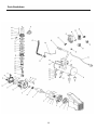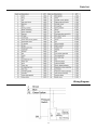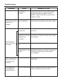
1
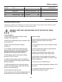
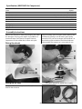
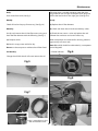
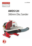
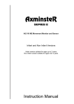
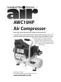
AWC10HP
Air Compressor
Direct drive, oil lubricated, ducted air cooled, portable compressor
A small, direct drive, oil lubricated, ducted air cooled, portable compressor. Great in the
workshop or around the home for low volume air tools such as air staplers and nailers,
air brush painting, occasional tyre inflation etc. Quite a robust little unit with a cast iron
cylinder for long life. Twin pressure gauges
monitor receiver and output pressures.
Supplied with four rubber feet, top grab
handle for easy mobility, output pressure
control valve and a 1/4” BSP female quick
release fitting.
Axminster Tool Centre,
Unit 10 Weycroft Avenue, Axminster, Devon EX13 5PH
www.axminster.co.uk
Index of Contents
Page No
Index of Contents............................................................................................................................................................................................. 02
Declaration of Conformity............................................................................................................................................................................. 02
What’s Included................................................................................................................................................................................................. 03
Safety Precautions............................................................................................................................................................................................ 03
Specifications (AWC10HP Air Compressor)............................................................................................................................................. 04
Assembly Instructions...............................................................................................................................................................................04-05
Illustration and Parts Description of Air Compressor............................................................................................................. 05-06-07
Operating Instructions....................................................................................................................................................................................08
Maintenance.......................................................................................................................................................................................................09
Parts Breakdown............................................................................................................................................................................................... 10
Parts List.............................................................................................................................................................................................................. 11
Wiring Diagram................................................................................................................................................................................................. 11
Trouble Shooting.............................................................................................................................................................................................. 12
Declaration of Conformity
manufactured by Qingdao D&D Electromechanical
Technologies Co., Ltd. is in compliance with the standards
determined in the following Council Directive.
Copied from CE Certificate
The undersigned, authorised by T. Fuhrmann
Manufactured by Qingdao D&D Electromechanical
Technologies Co., Ltd. 23rd FL., D&D Fortune Center
No. 182-6 Haier Road Qingdao, Shandong 266000
P.R. China.
EC Council Directive 2006/42/EC
Low Voltage Directive 2006/95/EC
Model number
RAC106B Air Compressor
symbols below advise that you follow the correct
Warning The
safety procedures when using this machine.
Fully read manual
and safety instructions
before use
Ear protection
should be worn
Eye protection
should be worn
02
Dust mask
should be worn
HAZARD
Motor gets hot
What’s Included
Quantity
1 off:
1 off
4 off
4 off
4 off
Item
Air Compressor
Bottle of oil
Rubber Feet
(A)
M6x25mm Bolts (B)
M6 Large Washers (C)
4 off Small Washers
4 off M6 Spring Washers
4 off M6 Nuts
1 off Filter
1 off Instruction Manual
(D)
(E)
(F)
(G)
Model Number
RAC106B
Safety Precautions
Good Working Practices/Safety
The following suggestions will enable you to observe good working practices, keep yourself and fellow workers
safe and maintain your tools and equipment in good working order.
WARNING!! KEEP TOOLS AND EQUIPMENT OUT OF THE REACH OF YOUNG
CHILDREN
Air Powered Tools
1. Always perform pre-operation checks before
starting up the compressor.
before re-starting.
2. Never leave inflammable objects or materials near
to the compressor.
10. Do not adjust the tank pressure switch without
reference to Axminster Power Tool Service
Department.
3. Always check oil level before using the
compressor.
11. Do not remove parts from the compressor whilst
it is running.
4. The cylinder, cylinder head and delivery pipe
become hot during use. Do not touch these items
while the compressor is running. Allow to cool
thoroughly after shut-down before handling.
12. Do not operate the compressor with protective
covers removed or damaged.
5. Do not operate above the maximum working
pressure of 115 psi (7.8 bar).
6. Avoid using the compressor with an extension
cable; this may reduce the supply voltage and make
the motor overheat.
7. Switch the compressor on and off by using the
pressure switch knob (Fig 3); only switch off at the
mains in case of emergency.
8. Drain water from tank every day.
13. When spray painting always work in a well
ventilated area and never close to open flames.
14. Never direct a jet of compressed air towards
people or animals. Keep children and animals away
from the compressor.
15. Do not use on an inclined surface.
16. Only use in ambient temperatures between –40˚C
and +70˚C.
17. Only operate on 230 volt supply and with
maximum fuse rating of 13 amps.
9. If the compressor shuts down through overload or
overheating check the reason for the shut-down
03
Specification (AWC10HP Air Compressor)
Code
Rating
Power
Free Air Delivered
Max Pressure
Noise Level at 3 meters
Receiver Volume
Oil Capacity
Supply Requirements
Overall L x W x H
Weight
501083
Light Trade
750W
@40psi - 3.5cfm, @ 90psi - 2.4cfm
115psi
70dB
6 litres
100ml
230V
515 x 240 x 465mm
14.5kg
Assembly Instructions
Remove the compressor from the packaging and check
for damage or missing parts. Report any problems to
Axminster Power Tool Centre’s Customer Services
Department. Fit the rubber feet, air filter and quick
release coupling. (see instructions below) Remove the
oil filler plug (See fig 2) and fill with a good quality
compressor oil, (see our catalogue) until the level is in
line with the circle marked on the oil level indicator.
(See page 05) The compressor is now ready for use.
Fitting the wheels
A
C
B
E
D
F
Use 10mm spanners to tighten the assembly
Fitting the air filter
Un-clip the filter container, place the filter (G) inside and
reattach the container.
G
04
Assembly Instructions
Fitting the quick release coupling
B
A
Wrap some PTFE tape (A) around the outlet thread and
screw on the 1/4" BSP female coupling (B) and, lightly
tighten with a spanner. (DO NOT OVERTIGHTEN)
Illustration and Parts Description of Air Compressor
Oil drain plug
Oil level indicator
Tank pressure gauge (A) & Outlet pressure gauge (B)
Pressure regulator adjuster
A
B
Closed
Open
Pressure relief valve
05
Illustration and Parts Description of Air Compressor
Fig 1
Motor cover
Handle
Cylinder
On/Off switch
Pressure switch
Pressure adjuster
Outlet pressure
gauge
Tank pressure
gauge
Crankcase
Pressure
relief valve
Wheel
Tank
Rubber foot
Water drain valve
06
Illustration and Parts Description of Air Compressor
Motor vents
Filter
Pressure adjuster
Air inlet filter
Fig 2
Quick release
coupling
Oil filler plug
Oil level
indicator and
drain plug
07
Operating Instructions
The outlet air pressure can be regulated by rotating the
regulator knob clockwise to increase the pressure and
anticlockwise to reduce it. Do not leave the regulator
set at maximum setting unnecessarily; reduce the
setting by about two turns after finishing and then
re-set to the required pressure when starting work
again.
drops below a pre-set level. The cut-in and cut-out
pressures are factory set and should not need to be
altered.
Connect the compressor to the mains supply and
switch on by pulling the on/off knob upwards. (See figs
3-4) Check that the compressor pressurises the tank
and shuts off when the maximum tank pressure is
reached.
The compressor is automatic in operation; the pressure
switch shuts the motor off when the maximum tank
pressure is reached and re-starts it when the pressure
Do not use dirty or non detergent oil.
NOTE: It is advisable to fully drain the air from the
tank if the compressor is left unused overnight, this
will prevent the build-up of water in the tank.
Do not operate compressor in an ambient
temperature above 40˚C.
Do not operate in a badly ventilated area.
Keep the air filter clean.
Fig 3
Pull up for (ON)
Fig 4
Push down for (OFF)
08
Maintenance
Daily:
Drain water from tank. (See fig 5)
filler plug, place a suitable container under the drain
plug and drain the oil right out. Replace drain plug and
refill to the level mark on the sight glass (See figs 6-8).
Weekly:
Yearly:
Check oil level and top-up if necessary. (See fig 6-8)
(a) Replace the air filter element.
Monthly:
(b) Check and clean the air intake and delivery valves.
Un-clip and remove the air inlet filter outer casing and
clean the filter element with the following: (See fig 7)
(c) Check the non return - valve and replace the seal
between the crankcase and cover if necessary.
(a) Compressed air.
When components are removed for servicing, take the
opportunity to fit new seals.
(b) Wash in soapy water and left to dry.
Do not use the compressor without the air filter fitted.
Note: (b) and (c) should be undertaken by a competent
service engineer.
Oil level indicator
Six Monthly:
Fig 6
Change the oil. With the oil still warm remove the oil
Fig 5
Fig 8
Fig 7
Using a screwdriver un-clip
the air inlet filter cover
09
Parts Breakdown
10
Parts List
Wiring Diagram
11
Trouble Shooting
PROBLEM
CAUSE
REMEDIAL ACTION
Tank pressure drops.
Leakage at
connections
or joints.
Set the compressor to maximum pressure.
Switch off and brush a soapy water solution
onto all connections and joints. Look for
bubbles. Tighten connections or joints where
leakage is visible.
The pressure switch
valve leaks when the
compressor is
stopped
Non-return valve seal
dirty or defective
Release any air in tank. Remove non-return valve
seal. If necessary, replace the seal. Re-assemble
Bad electrical
connections
Check the connections. Clean and tighten as
necessary
Current over-load
Press the reset button on the current over-load
protector or over-heat and wait for a minute. The motor will run when
protector has
it has cooled
activated.
The compressor
stops and will not
start again
Motor winding burnt
out
Contact Axminster Tool Centre
Compressor head
Wait for compressor to cool down. Disassemble
gasket blown or valve the head and replace any broken components.
broken
Carefully clean all sealing surfaces before
re-assembling
The compressor
does not reach the
set pressure and
overheats
Crank bearing failure
The compressor is
noisy. Repetitive
metallic clanking
Pressure switch failure Stop the compressor quickly. Release any air in
tank and replace the pressure switch
Stop the compressor and contact Axminster
Tool Centre
12