1
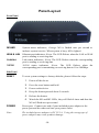
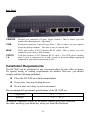
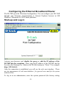
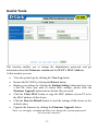
DI-704P Ethernet Broadband Router User’s Manual (Please refer to the Quick Install Guide for installation instructions.) Table of Contents Introduction ..................................................................................................4 Functions and Features.........................................................................4 Introduction to Broadband Router Technology....................................6 Introduction to Firewalls ......................................................................6 Introduction to Local Area Networking ...............................................7 Introduction to Virtual Private Networking..........................................7 Contents of Package .....................................................................................9 Panel Layout ...............................................................................................10 Installation Requirements ................................................................... 11 Network Settings ........................................................................................12 Configuring the Ethernet Broadband Router..............................................14 Start- up and Log in .............................................................................14 Device Information.............................................................................16 Useful Tools........................................................................................17 Setup ...................................................................................................18 DHCP Server ......................................................................................21 Virtual Server......................................................................................22 Special Applications ...........................................................................23 Access Control....................................................................................24 Miscellaneous Items ...........................................................................25 MAC Address Control........................................................................26 Configuring on Unix based Platforms ................................................27 Appendix A: Resetting the System Password or the IP Address ............28 Appendix B TCP/IP Configuration for Windows 95/98 .........................29 -2- B.1 Install TCP/IP Protocol into Your PC ..........................................29 B.2 Set TCP/IP Protocol for Working with the DI-704P ...................31 Technical Specifications .............................................................................38 Contacting Technical Support ....................................................................40 D-Link Locations Worldwide .....................................................................41 Limited Warranty........................................................................................43 Registration.................................................................................................47 -3- Introduction Congratulations on your purchase of this outstanding Broadband Router. The DI-704P is specifically designed for Small Office and Home Office needs. It provides a complete solution for Internet surfing and office resources sharing, and it is easy to configure and operate for even non-technical users. Instructions for installing and configuring the DI-704P can be found in the enclosed “Quick Install Guide.” Before you install and use the DI-704P, please read this manual carefully for more detailed information and to fully utilize its functions. Functions and Features l Broadband modem and IP sharing Connects multiple computers to a broadband (cable or DSL) modem to surf the Internet. l Auto-sensing Ethernet Switch Equipped with a 4-port auto-sensing Ethernet switch. l VPN supported Supports multiple PPTP sessions and allows you to setup VPN server and VPN clients. l Printer sharing (Optional) Embeds a print server to allow all of the networked computers to share one printer. l Firewall All unwanted packets from outside intruders are blocked to protect your network. l DHCP server supported All of the networked computers can retrieve TCP/IP settings automatically from the DI-704P. l Web-based configuring Configurable through any networked computer’s web browser using Netscape or Internet Explorer. -4- l Access Control supported Allows you to assign different access rights for different users. l Virtual Server supported Enables you to expose WWW, FTP and other services on your LAN to be accessible to Internet users. l User-Definable Application Sensing Tunne l User can define the attributes to support the special applications requiring multiple connections, like Internet gaming, video conferencing, Internet telephony and so on; then the DI-704P can sense the application type and open a multi-port tunnel for it. l DMZ Host supported Allows a networked computer to be fully exposed to the Internet; this function is used when the special “application-sensing tunnel feature” is insufficient to allow an application to function correctly. -5- Introduction to Broadband Router Technology A router is a device that forwards data packets from a source to a destination. Routers forward data packets using IP addresses and not a MAC address. A router will forward data from the Internet to a particular computer on your LAN. The information that makes up the Internet gets moved around using routers. When you click on a link on a web page, you send a request to a server to show you the next page. The information that is sent and received from your computer is moved from your computer to the server using routers. A router also determines the best route that your information should follow to ensure that the information is delivered properly. A router controls the amount of data that is sent through your network by eliminating information that should not be there. This provides security for the computers connected to your router, because computers from the outside cannot access or send information directly to any computer on your network. The router determines which computer the information should be forwarded to and sends it. If the information is not intended for any computer on your network, the data is discarded. This keeps any unwanted or harmful information from accessing or damaging your network. Introduction to Firewalls A firewall is a device that sits between your computer and the Internet that prevents unauthorized access to or from your network. A firewall can be a computer using firewall software or a special piece of hardware built specifically to act as a firewall. In most circumstances, a firewall is used to prevent unauthorized Internet users from accessing private networks or corporate LAN’s and Intranets. A firewall watches all of the information moving to and from your network and analyzes each piece of data. Each piece of data is checked against a set of criteria that the administrator configures. If any data does not meet the criteria, that data is blocked and discarded. If the data meets the criteria, the data is passed through. This method is called packet filtering. A firewall can also run specific security functions based on the type of application or type of port that is being used. For example, a firewall can be configured to work with an FTP or Telnet server. Or a firewall can be configured to work with specif ic UDP or TCP ports to allow certain applications or games to work properly over the Internet. -6- Introduction to Local Area Networking Local Area Networking (LAN) is the term used when connecting several computers together over a small area such as a build ing or group of buildings. LAN’s can be connected over large areas. A collection of LAN’s connected over a large area is called a Wide Area Network (WAN). A LAN consists of multiple computers connected to each other. There are many types of media that can connect computers together. The most common media is CAT5 cable (UTP or STP twisted pair wire.) On the other hand, wireless networks do not use wires; instead they communicate over radio waves. Each computer must have a Network Interface Card (NIC), whic h communicates the data between computers. A NIC is usually a 10Mbps network card, or 10/100Mbps network card, or a wireless network card. Most networks use hardware devices such as hubs or switches that each cable can be connected to in order to continue the connection between computers. A hub simply takes any data arriving through each port and forwards the data to all other ports. A switch is more sophisticated, in that a switch can determine the destination port for a specific piece of data. A switch minimizes network traffic overhead and speeds up the communication over a network. Networks take some time in order to plan and implement correctly. There are many ways to configure your network. You may want to take some time to determine the best network set-up for your needs. Introduction to Virtual Private Networking Virtual Private Networking (VPN) uses a publicly wired network (the Internet) to securely connect two different networks as if they were the same network. For example, an employee can access the corporate network from home using VPN, allowing the employee to access files and printers. Here are several different implementations of VPN that can be used. -7- Point-to-Point Tunneling Protocol (PPTP) PPTP uses proprietary means of connecting two private networks over the Internet. PPTP is a way of securing the information that is communicated between networks. PPTP secures information by encrypting the data inside of a packet. IP Security (IPSec) IPSec provides a more secure network-to-network connection across the Internet or a Wide Area Network (WAN). IPSec encrypts all communication between the client and server whereas PPTP only encrypts the data packets. Both of these VPN implementations are used because there is not a standard for VPN server software. Because of this, each ISP or business can implement its own VPN network making interoperability a challenge. -8- Contents of Package DI - 704P Ethernet Broadband Router DI-704P Ethernet Broadband Router Installation CD-ROM Power cord and power adapter CAT-5 UTP Fast Ethernet Cable -9- Panel Layout Front Panel M1&M2 WAN & LAN Link/Act. 10/100 System status indicators, Orange. M1 is flashed once per second to indicate system is active. When system is busy, M2 is lighted. Ethernet port indicators, Green. The LED flickers when the LAN or WAN port is sending or receiving data. Link status indicators, Green. The LED flickers when the corresponding port is sending or receiving data 10/100 status indicators, Green. The LED flickers when the corresponding port is transmitting or receiving data in 10 or 100Mbps. Side Panel RESET To reset system settings to factory defaults, please follow the steps: 1. Power off the device 2. Press the reset button and hold 3. Power on the device 4. Keep the button pressed about 5 seconds 5. Release the button 6. Watch the M1 and M2 LEDs, they will flash 8 times and then the M1 will flash once per second POWER Power port. Connect one end of your included power adapter to the power port and the other end into your power outlet Note: The included power adapter is DC 5V/1A. Using the wrong type of power adapter may cause product damage. -10- Rear Panel PRINTER COM WAN PORTS 1-4 Parallel port connector (25-pins D-type female.) This is where you will connect the shared printer. (Optional) Serial port connector (9-pins D-type male.) This is where you can connect a back-up dial-up modem. This port is also a console port. WAN port socket (CAT5 Ethernet RJ-45 cable). This is where you will connect to your cable or DSL modem. LAN port sockets (CAT5 Ethernet RJ-45 cable.) The LED glows steadily when a port is connected to a hub, switch or network-adapter-equipped computer in your local area network (LAN.) Installation Requirements The DI-704P can be positioned at any convenient place in your office or house. No special wiring or cooling requirements are needed. However, you should comply with the following guidelines: l Place the DI-704P on a flat horizontal plane. l Keep away from any heating devices. l Do not place in a dusty or wet environment. The recommended operational specifications of the DI-704P are: Temperature 32o F ~ 131o F Humidity 5 % ~ 90 % In addition, remember to turn off the power, remove the power cord from the outlet, and keep your hands dry when you install the hardware. -11- Network Settings To use the DI-704P correctly, you have to properly configure the network settings of your computers. The default IP address of the DI-704P is 192.168.0.1, and the default subnet mask is 255.255.255.0. These addresses can be changed as needed, but the default values are used in this manual. If the TCP/IP environment of your computer has not yet been configured, you can refer to Appendix B to configure it. For example, 1. configure IP as 192.168.0.3, subnet mask as 255.255.255.0 and gateway as 192.168.0.1, or more conveniently, 2. configure your computers to load TCP/IP setting automatically, that is, via the DHCP server of the DI-704P. After installing the TCP/IP communication protocol, you can use the ping command to check if your computer has successfully connected to the DI-704P. The following example shows the ping procedure for Windows 95 platforms. First, execute the ping command ping 192.168.0.1 If the following messages appear: Pinging 192.168.0.1 with 32 bytes of data: Reply from 192.168.0.1: bytes=32 time=2ms TTL=64 a communication link between your computer and the DI-704P has been successfully established. However, if you get the following messages: Pinging 192.168.0.1 with 32 bytes of data: Request timed out. this indicates that the installation is not successful. Please check the following items in sequence: 1. Is the Ethernet cable correctly connected between the DI-704P and your computer? The LAN LED of the DI-704P and the link LED of the network adapter card on your computer must be lighted. -12- 2. Is the TCP/IP of your computers properly configured? If the IP address of the DI-704P is 192.168.0.1, the IP address of your computer must be 192.168.0.X (where “X” is a number between 2 and 254. Each computer on your network must have a different IP address within that range where “X” represents a number between 2 and 254.) The default gateway must be 192.168.0.1. -13- Configuring the Ethernet Broadband Router The DI-704P provides Web based configuration. You can configure your DI-704P through your Netscape Communicator or Internet Explorer browser in MS Windows, Macintosh or UNIX based platforms. Start-up and Log in Activate your browser, and disable the proxy or add the IP address of the DI-704P into the exceptions . Then, type the IP address of the DI-704P into the Location (for Netscape) or Address (for IE) field and press “Enter.” For example: http://192.168.0.1. After the connection is established, you will see the web user interface. There are two appearances of web user interface: for general users and for the system administrator. To log in as an administrator, enter the system password (the factory setting -14- is ”admin”) in the System Password field and click on the Log in button. If the password is correct, the web appearance will be changed into administrator configure mode. As listed in its main menu, there are several options for system administration. -15- Device Information This option allows you to observe the DI-704P’s working status: A. Modem Status B. Printer Status. The possible kinds of printer status include “Ready,” “Not ready,” “Printing…,” and “Device error.” When a job is printing, there may appear a “Kill Job” button on the “Sidenote” column. You can click this button to stop the current printing job manually. -16- Useful Tools This function enables you to change the administrator password, and get information about the Firmware version and the WAN's MAC Address. At this window you can: • • • View the system logs by clicking the View Log button. Restart the DI-704P by clicking the Reboot button. Backup your settings by clicking the Backup Setting button and save it as a bin file. Once you want to restore these settings, please click the Firmware Upgrade button and use the bin file you saved. • Click the Clone MAC button to copy the MAC address of your PC to be the MAC address of this device. • Click the Reset to Default button to reset the settings of this device to the default values. • Upgrade the firmware by clicking the Firmware Upgrade button. Note: we strongly recommend that you change the system password for security reasons. -17- Setup Before you begin the Setup, you must choose the correct WAN type. 1. LAN IP Address: the DI-704P’s IP address. The default address is 192.168.0.1. You can change the LAN IP Address if needed. 2. WAN Type: your ISP’s WAN Connection type. Click the Change button to choose from the following five options: A. Static IP Address: you manually input the IP Address that your ISP assigned to you. B. Dynamic IP Address: Obtain an IP address automatically from the DI-704P’s DHCP Server function. C. PPP over Ethernet: Some ISPs require the use of PPPoE to connect to their services. D. Dial-up Network : To surf the Internet via PSTN/ISDN (a dial-up modem.) E. PPTP: Some ISPs require the use of PPTP to connect to their services. It is specifically for many European ISPs where Alcatel’s ADSL Network Termination is deployed. -18- Below are the five WAN types and the fields required to implement them: 1. Static IP Address Enter the proper setting provided by your ISP for the following fields: WAN IP Address, Subnet Mask, Gateway, Primary and Secondary DNS 2. Dynamic IP Address • • 3. PPP over Ethernet • • • 4. Host Name: optional. Required by some ISPs, for example, @Home. Renew IP Forever: this feature enables the DI-704P to renew the IP address automatically when the lease time is expired even if the system is in an idle state. PPPoE Account and Password: the account and password your ISP assigned to you. If you don't want to change the password, leave the password field blank. PPPoE Service Name: (optional) Input the service name if your ISP requires it. Maximum Idle Time: set the length of “no activity” time at which to disconnect your PPPoE session. Setting it to “0” will disable this feature. Dial-up Network • Dial-up Telephone, Account and Password : assigned by your ISP. If you don't want to change the password, keep it empty. • Primary and Secondary DNS : automatically assigned if they are configured as "0.0.0.0." • Maximum Idle Time: the length of “no activity” time at which to disconnect your dial-up session. • Baud Rate : the communication speed between the DI-704P and your MODEM or ISDN TA. • Extra Setting: needed to optimize the communication quality between the ISP and your MODEM or ISDN TA -19- 5. PPTP Just follow steps below to configure the PPTP WAN type: • Set My IP Address as the IP address that the ISP assigned to your PC, e.g. 10.0.0.140. • Set My Subnet Mask as the mask that the ISP assigned to your PC, e.g. 255.255.255.0. • Set Server IP Address as the IP address of the DSL modem, e.g. 10.0.0.138. • Input the PPTP Account and Password. • Input the Connection ID if your ISP requires it. • Save the setting and restart the router. • In the Command prompt, type PING 4.0.0.1. If the reply is positive, the router and your PC have been successfully configured for PPTP WAN type. -20- DHCP Server The DI-704P includes a DHCP Server. If you select “Enable” the DHCP Server, and you configure the computers on your network to “Obtain an IP Address automatically,” then when you turn your computer “ON,” it will automatically load the proper TCP/IP settings from the DI-704P. You will not have to configure all the TCP/IP settings for your network manually. The settings for the DHCP server are as follows: 1. DHCP Server: Choose “Disable” or “Enable.” 2. The range of the IP Address Pool: Whenever there is a request, the DHCP server will automatically allocate an unused IP address from the IP address pool to the requesting computer. You must specify the starting and ending address of the IP address pool. 3. Domain Name : Optional, this information will be passed to the client. To View the DHCP clients, you can click the Clients List button. -21- Virtual Server The firewall filters out unrecognized packets to protect your Intranet; so all computers networked with the DI-704P are invisible to the outside world. If you wish, you can make some of them accessible by enabling the Virtual Server Mapping. A virtual server is defined as a Service Port, and all requests to this port will be redirected to the computer specified by the Server IP. For example, if you have an FTP server (port 21) at 192.168.0.1, a Web server (port 80) at 192.168.0.2, and a VPN server at 192.168.0.6, then you need to specify the following virtual server-mapping table: Service Port Server IP Enable 21 192.168.0.1 V 80 192.168.0.2 V 1723 192.168.0.6 V -22- Special Applications Some applications require multiple connections, like Internet games, Video conferencing, Internet telephony and so on. Due to the firewall function, these applications cannot work without some intervention. Spe cial Applications makes some of these applications work with the DI-704P. If Special Applications is still insufficient to allow an application to function correctly, try the DMZ Host in the Miscellaneous Items options. Trigger: the outbound port number the application issued first. Incoming Ports: when the trigger packet is detected, the inbound packets to the specified port numbers are allowed to pass the firewall. The DI-704P provides some predefined settings in the gray pad on the bottom of the web page. Select your application in the Popular applications pull-down menu and click Copy to in order to copy the predefined setting. Note! At any time, only one PC can use each Special Application tunnel. -23- Access Control Access Control allows you to assign different access rights for different users. First, you have to divide users into different groups. Users are identified by their IP addresses. You can assign members to Groups 1, 2 and 3. The others are all members of the Default Group. Next, you have to assign the Access Right of each group. Access Right can allow or block users access to specified TCP and UDP ports. For example: Group Members Default - Group 1 100-199 Group 2 Group 3 Access Right Comments Allow () No access right (allow nothing) Allow (25,53,80,110) Can browse (80), receive (110) and send (25) email only 50-99 Block (21,119) Cannot read net news (119) and FTP (21) only 1-9,20 Block () Full access (block nothing) -24- Miscellaneous Items IP Address of the DMZ Host: The DMZ (Demilitarized Zone) Host is a host without the protection of a firewall. It allows a computer to be exposed to unrestricted 2-way communication. (Note: this feature should be used only when needed.) Remote Administrator Host: In general, only a member of your network can browse the built-in web pages to perform “Administrator” tasks. This feature enables you to perform “Administrator” tasks from the remote host. If this feature is enabled, only the specified IP address can perform remote administration. If the specified IP address is 0.0.0.0, any host can connect to the DI-704P to perform “Administrator” tasks. When this feature is enabled, the web port will be shifted to 88. Non-standard FTP port: You have to configure this item if you want to access an FTP server whose port number is not 21. This setting will be lost after rebooting. -25- MAC Address Control MAC Address Control allows you to assign different access rights for different users and to assign a specific IP address to a certain MAC address. MAC Addre ss Control Check Enable to enable the MAC Address Control. All of the settings in this page will take effect only when Enable is checked. Connection control Check Connection control to control what wired and wireless clients can connect to this device. If a client is denied connection to this device, it means the client can't access the Internet either. Choose "allow" or "deny" to allow or deny the clients, whose MAC addresses are not in the "Control table" (please see below), to connect to this device. -26- MAC Address IP Address C MAC address indicates a specific client. Expected IP address of the corresponding client. You may choose to leave this field empty. When " Connection control" is checked, check "C" to allow the corresponding client to connect to this device. Near the bottom of the MAC Address Control window, the following pull-down menu and button will help you to input the MAC address. Select a specific client in the “DHCP clients” pull-down menu. Click on the “Copy to” button to copy the MAC address of the DHCP client you select to the ID selected in the “ID” pull-down menu. Previous page and Next PageAt the bottom of the MAC Address Control window you will find these two buttons. Use them to navigate between the several pages of the MAC Address Control function. Configuring on Unix based Platforms Please follow the traditional configuration procedure on Unix platforms to setup the print server of the DI-704P. The printer name is “lp.” -27- Appendix A: Resetting the System Password or the IP Address When you forget the system password or the IP address of the DI-704P, you will need to reset them. Use a null modem cable (an RS-232 cable) to connect your computer and the DI-704P using the serial ports of both machines (the com port on the DI-704P is a serial port.) After you have made the connection, launch a terminal program, such as the Hyper Terminal of MS Windows 95. The connection parameters should be set to 19200 8-N-1. Reboot the DI-704P. When the M1 indicator starts flashing regularly, you can press the “Enter” key of the keyboard several times, there should be some messages and a console prompt ">" will appear. You may reset the IP address and the system password of the DI-704P. Please remember to execute the SR command to save the changes you have made. For example, IP 192.168.0.1 PW admin SR -28- Appendix B TCP/IP Configuration for Windows 95/98 This section shows you how to install TCP/IP protocol into your personal computer after you have successfully installed one network card. (If you have not, please refer to your network card manual.) Section B.2 tells you how to set TCP/IP values for working with the DI-704P. B.1 Install TCP/IP Protocol into Your PC 1. Go to Start > Settings, then click Control Panel. 2. Double click the Network icon and select the Configuration tab in the Network window. 3. Click the Add button. 4. Double click Protocol to add TCP/IP protocol. -29- 5. Select Microsoft in the Manufacturers list. And choose TCP/IP in the Network Protocols list. Click OK to return to the Network window. 6. The TCP/IP protocol will be listed in the Network window. Click OK to complete the install procedure. Restart your PC to enable the TCP/IP protocol. -30- B.2 Set TCP/IP Protocol for Working with the DI-704P 1. Go to Start > Settings, then click Control Panel. 2. Double click the Network icon. Select the TCP/IP line that has been associated to your network card in the Configuration tab of the Network window. 3. Click the Properties button to set the TCP/IP protocol for the DI-704P. 4. You have two ways of setting the TCP/IP. First, by obtaining an IP address automatically and second, by specifying a static IP address: A. Obtaining an IP address automatically from the DHCP server (also called a “dynamic IP address.”) -31- a. Select Obtain an IP address automatically in the IP Address tab. -32- b. Don’t input any value in the Gateway tab. -33- c. Choose Disable DNS in the DNS Configuration tab -34- B. The second way to get an IP address is to input one manually as follows: a. Select Specify an IP address in the IP Address tab. The default IP address of the DI-704P is 192.168.0.1. So please use 192.168.0.xxx (where xxx is between 2 and 254) for the IP Address field and 255.255.255.0 for Subnet Mask field. -35- b. In the Gateway tab, add the IP address of the DI-704P (the default IP is 192.168.0.1) in the New gateway field and click the Add button. -36- c. In the DNS Configuration tab, add the DNS values which are provided by the ISP into DNS Server Search Order field and click the Add button. -37- Technical Specifications Standards: • IEEE 802.3 10BASET-T Ethernet • IEEE 802.3u 100BASE-TX Fast Ethernet • IEEE 802.3x Flow Control • IEEE 802.1p Priority Queue • ANSI/IEEE 802.3 NWay auto-negotiation Management: • Web-Based VPN Pass Through Function*: • PPTP • L2TP • IPSec Ports: • 4 x NWay 10BASE-T/100BASE-TX Fast Ethernet LAN (Media Auto Sensing) • 1 x 10BASE-T WAN • 1 x RS-232 (DB-9) • 1 Printer Port (Female DB-25) LED’s: • WAN Activity • LAN Link Activity • M1 – Status • M2 – Status Power: • DC 5V 2A -38- Weight: • 1.74 kg (3.83 lb) Size: • 300(W) x 142(D) x 40(H) mm Operating Temperature: • 5 C ~ 55 C Humidity: • 10% ~ 90% -39- Contacting Technical Support You can find the most recent software and user documentation on the D-Link website. D-Link provides free technical support for customers within the United States for the duration of the warranty period on this product. U.S. customers can contact D-Link technical support through our web site, by e-mail, or by phone. United States technical support is available Monday through Friday from 6:00 a.m. to 6:00 p.m. (PST.) Web: http://www.dlink.com E-mail: [email protected] Phone: 949-788-0805 (option #4) If you are a customer residing outside of the United States, please refer to the list of D-Link locations that is included in this manual. Thank you for purchasing this product. We like to receive feedback from our customers concerning our products. Please take a moment to visit our web site. You can register your purchase on-line, learn more about the newest networking products, and let us know the things your new network has empowered you to do. -40- D-Link Locations Worldwide D-Link Australia Unit 16, 390 Eastern Valley Way Roseville, NSW 2069, Australia TEL: 61-2-94177100 FAX: 61-2-94171077 URL: www.dlink.com.au D-Link Middle East 7 Assem Ebn Sabet Street Heliopolis Cairo Egypt TEL: 20-2-6356176 FAX: 20-2-6356192 URL: www.dlink-me.com D-Link Benelux Fellenoord 1305611 ZB EindhovenThe Netherlands TEL: 31-40-2668713 FAX: 31-40-2668666 URL: www.dlink-benelux.nl/ D-Link Finland Thlli-ja Pakkahuone Katajanokanlaituri 5 FIN-00160 Helsinki Finland TEL: 358-9-622-91660 FAX: 358-9-622-91661 URL: www.dlink-fi.com D-Link Canada #2180 Winston Park Drive Oakville, Ontario, L6H 5W1 Canada TEL: 1-905-8295033 FAX: 1-905-8295095 URL: www.dlink.ca D-Link France Le Florilege #.2, Allee de la Fresnerie 78330 Fontenay le Fleury France TEL: 33-1-30238688 FAX: 33-1-30238689 URL: www.dlink-france.fr D-Link China 2/F., Sigma Building, 49 Zhichun Road, Haidian District, 100080 Beijing, China TEL: 86-10-88097777 FAX: 86-10-88096789 D-Link Germany Schwalbacher Strasse 74 D-65760 Eschborn Germany TEL: 49-6196-77990 FAX: 49-6196-7799300 URL: www.dlink.de D-Link South America Isidora Goyeechea 2934 of 702, Las Condes Santiago ¡V Chile S.A. TEL: 56-2-232-3185 FAX: 56-2-232-0923 URL: www.dlink.cl D-Link India Plot No.5, Kurla-Bandra Complex Rd. Off Cst Rd. Santacruz (E), Bombay - 400 098 India TEL: 91-22-652-6696 FAX: 91-22-652-8914 URL: www.dlink-india.com D-Link Denmark Naverland 2, DK-2600 Glostrup, Copenhagen, Denmark TEL: 45-43-969040 FAX: 45-43-424347 URL:www.dlink.dk -41- D-Link Italia via Nino Bonnet n. 6/b 20154 ¡V Milano, Italy TEL: 39-02-2900-0676 FAX: 39-02-2900-1723 URL: www.dlink.it D-Link South Africa 102 - 106 Witchhazel Avenue Einstein Park 2 Block B Highveld Technopark Centurion South Africa TEL: 27(0)126652165 FAX: 27(0)126652186 D-Link Japan 10F, 8-8-15 Nishi-Gotanda Shinagawa-ku, Tokyo 141, Japan TEL: 81-3-5434-9678 FAX: 81-3-5434-9868 URL: www.d-link.co.jp D-Link Spain Gran Via de Carlos III, 843¢X Edificio Trade08028 BARCELONA TEL: 34 93 4965751 FAX: 34 93 4965701 URL: www.dlinkiberia.es D-Link Norway Waldemar Thranesgt. 77, 0175 OsloNorway TEL: 47-22-991890 FAX: 47-22-207039 D-Link Sweden P.O. Box 15036, S-167 15 Bromma Sweden TEL: 46-(0)8564-61900 FAX: 46-(0)8564-61901 URL: www.dlink.se D-Link Russia Michurinski Prospekt 49, 117607 Moscow, Russia TEL: 7-095-737-3389, 7-095-737-3492 FAX: 7-095-737-3390 D-Link Taiwan 2F, No. 119 Pao-Chung Rd. Hsin-Tien, Taipei Taiwan TEL: 886-2-2910-2626 FAX: 886-2-2910-1515 URL: www.dlinktw.com.tw D-Link International (Singapore) 1 International Bussiness Park #03-12 The Synergy Singapore 609917 TEL: 65-774-6233 FAX: 65-774-6322 URL: www.dlink-intl.com D-Link U.K.(Europe) 4th Floor, Merit House Edgware Road, Colindale London NW9 5AB U.K. TEL: 44-20-8731-5555 FAX: 44-20-8731-5511 BBS: 44-181-235-5511 URL: www.dlink.co.uk D-Link U.S.A 53 Discovery Drive Irvine, CA 92618 U.S.A. TEL: 1-949-788-0805 FAX: 1-949-753-7033 URL: www.dlink.com -42- Limited Warranty D-Link Systems, Inc. (“D-LINK”) provides this limited warranty for its product only to the person or entity who originally purchased the product from D-Link or its authorized reseller or distributor. Limited Hardware Warranty: D-Link warrants that the hardware portion of the D-Link products described below (“Hardware”) will be free from material defects in workmanship and materials from the date of original retail purchase of the Hardware, for the period set forth below applicable to the product type (“Warranty Period”) if the Hardware is used and serviced in accordance with applicable documentation; provided that a completed Registration Card is returned to an Authorized D-Link Service Office within ninety (90) days after the date of original retail purchase of the Hardware. If a completed Registration Card is not received by an authorized D-Link Service Office within such ninety (90) period, then the Warranty Period shall be ninety (90) days from the date of purchase. Product Type Warranty Period Product (excluding power supplies and fans), if purchased and delivered in the fifty (50) United States, or the District of Columbia (“USA”) One (1) Year, limited Product purchased or delivered outside the USA One (1) Year Power Supplies and Fans One (1) Year Spare parts and spare kits Ninety (90) days D-Link’s sole obligation shall be to repair or replace the defective Hardware at no charge to the original owner. Such repair or replacement will be rendered by D-Link at an Authorized D-Link Service Office. The replacement Hardware need not be new or of an identical make, model or part; D-Link may in its discretion may replace the defective Hardware (or any part thereof) with any reconditioned product that D-Link reasonably determines is substantially equivalent (or superior) in all material respects to the defective Hardware. The Warranty Period shall extend for an additional ninety (90) days after any repaired or replaced Hardware is delivered. If a material defect is incapable of correction, or if D-Link determines in its sole discretion that it is not practical to repair or replace the defective Hardware, the price paid by the original purchaser for the defective Hardware will be refunded by D-Link upon return to D-Link of the defective Hardware. All Hardware (or part thereof) that is replaced by D-Link, or for which the purchase price is refunded, shall become the property of D-Link upon replacement or refund. Limited Software Warranty: D-Link warrants that the software portion of the product (“Software”) will substantially conform to D-Link’s then current functional specifications for the Software, as set forth in the applicable documentation, from the date of original delivery of the Software for a period of ninety (90) days (“Warranty Period”), if the Software is properly installed on approved hardware and operated as contemplated in its documentation. D-Link further warrants that, during the Warranty Period, the magnetic media on which D-Link delivers the Software will be free of physical defects. D-Link’s sole obligation shall be to replace the non-conforming Software (or defective media) with software that substantially conforms to D-Link’s functional specifications for the Software. Except as otherwise agreed by D-Link in writing, the replacement Software is provided only to the original licensee, and is subject to the terms and conditions of the license granted by D-Link for the Software. The Warranty Period shall extend for an additional ninety (90) days after any replacement Software is delivered. If a material non-conformance is incapable of correction, or if D-Link determines in its sole discretion that it is not practical to replace the non-conforming Software, the price paid by the original licensee for the non-conforming Software will be refunded by D-Link; provided that the non-conforming Software (and all copies thereof) is first returned to D-Link. The license granted respecting any Software for which a refund is given automatically terminates. What You Must Do For Warranty Service: Registration Card. The Registration Card provided at the back of this manual must be completed and returned to an Authorized D-Link Service Office for each D-Link product within ninety (90) days after the product is purchased and/or licensed. The addresses/telephone/fax list of the nearest Authorized D-Link Service Office is provided in the back of this manual. FAILURE TO PROPERLY COMPLETE AND TIMELY RETURN THE REGISTRATION CARD MAY AFFECT THE WARRANTY FOR THIS PRODUCT. Submitting A Claim. Any claim under this limited warranty must be submitted in writing before the end of the Warranty Period to an Authorized D-Link Service Office. The claim must include a written description of the Hardware defect or Software nonconformance in sufficient detail to allow D-Link to confirm the same. The original product owner must obtain a Return Material Authorization (RMA) number from the Authorized D-Link Service Office and, if requested, provide written proof of purchase of the product (such as a copy of the dated purchase invoice for the product) before the warranty service is provided. After an RMA number is issued, the defective product must be packaged securely in the original or other suitable shipping package to ensure that it will not be damaged in transit, and the RMA number must be prominently marked on the outside of the package. The packaged product shall be insured and shipped to D-Link, 53 Discovery Drive, Irvine CA 92618, with all shipping costs prepaid. D-Link may reject or return any product that is not packaged and shipped in strict compliance with the foregoing requirements, or for which an RMA number is not visible from the outside of the package. The product owner agrees to pay D-Link’s reasonable handling and return shipping charges for any product that is not packaged and shipped in accordance with the foregoing requirements, or that is determined by D-Link not to be defective or non-conforming. -44- What Is Not Covered: This limited warranty provided by D-Link does not cover: Products that have been subjected to abuse, accident, alteration, modification, tampering, negligence, misuse, faulty installation, lack of reasonable care, repair or service in any way that is not contemplated in the documentation for the product, or if the model or serial number has been altered, tampered with, defaced or removed; initial installation, installation and removal of the product for repair, and shipping costs; operational adjustments covered in the operating manual for the product, and normal maintenance; damage that occurs in shipment, due to act of God, failures due to power surge, and cosmetic damage; and any hardware, software, firmware or other products or services provided by anyone other than D-Link. Disclaimer of Other Warranties: EXCEPT FOR THE LIMITED WARRANTY SPECIFIED HEREIN, THE PRODUCT IS PROVIDED “AS-IS” WITHOUT ANY WARRANTY OF ANY KIND INCLUDING, WITHOUT LIMITATION, ANY WARRANTY OF MERCHANTABILITY, FITNESS FOR A PARTICULAR PURPOSE AND NON-INFRINGEMENT. IF ANY IMPLIED WARRANTY CANNOT BE DISCLAIMED IN ANY TERRITORY WHERE A PRODUCT IS SOLD, THE DURATION OF SUCH IMPLIED WARRANTY SHALL BE LIMITED TO NINETY (90) DAYS. EXCEPT AS EXPRESSLY COVERED UNDER THE LIMITED WARRANTY PROVIDED HEREIN, THE ENTIRE RISK AS TO THE QUALITY, SELECTION AND PERFORMANCE OF THE PRODUCT IS WITH THE PURCHASER OF THE PRODUCT. Limitation of Liability: TO THE MAXIMUM EXTENT PERMITTED BY LAW, D-LINK IS NOT LIABLE UNDER ANY CONTRACT, NEGLIGENCE, STRICT LIABILITY OR OTHER LEGAL OR EQUITABLE THEORY FOR ANY LOSS OF USE OF THE PRODUCT, INCONVENIENCE OR DAMAGES OF ANY CHARACTER, WHETHER DIRECT, SPECIAL, INCIDENTAL OR CONSEQUENTIAL (INCLUDING, BUT NOT LIMITED TO, DAMAGES FOR LOSS OF GOODWILL, WORK STOPPAGE, COMPUTER FAILURE OR MALFUNCTION, LOSS OF INFORMATION OR DATA CONTAINED IN, STORED ON, OR INTEGRATED WITH ANY PRODUCT RETURNED TO D-LINK FOR WARRANTY SERVICE) RESULTING FROM THE USE OF THE PRODUCT, RELATING TO WARRANTY SERVICE, OR ARISING OUT OF ANY BREACH OF THIS LIMITED WARRANTY, EVEN IF D-LINK HAS BEEN ADVISED OF THE POSSIBILITY OF SUCH DAMAGES. THE SOLE REMEDY FOR A BREACH OF THE FOREGOING LIMITED WARRANTY IS REPAIR, REPLACEMENT OR REFUND OF THE DEFECTIVE OR NON-CONFORMING PRODUCT. GOVERNING LAW : This Limited Warranty shall be governed by the laws of the state of California. Some states do not allow exclusion or limitation of incidental or consequential damages, or limitations on how long an implied warranty lasts, so the foregoing limitations and exclusions may not apply. This limited warranty provides specific legal rights and the product owner may also have other rights which vary from state to state. -45- FCC Statement This equipment has been tested and found to comply with the limits for a Class B digital device, pursuant to Part 15 of the FCC Rules. These limits are designed to provide reasonable protection against harmful interference in a residential installation. This equipment generates, uses and can radiate radio frequency energy and, if not installed and used in accordance with the instructions, may cause harmful interference to radio communications. However, there is no guarantee that interference will not occur in a particular installation. If this equipment does cause harmful interference to radio or television reception, which can be determined by turning the equipment off and on, the user is encouraged to try to correct the interference by one or more of the following measures: • Reorient or relocate the receiving antenna. • Increase the separation between the equipment and receiver. • Connect the equipment into an outlet on a circuit different from that to which the receiver is connected. • Consult the dealer or an experienced radio/TV technician for help. Shielded interface cables must be used in order to comply with emission limits. You are cautioned that changes or modifications not expressly approved by the party responsible for compliance could void your authority to operate the equipment. This device complies with Part 15 of the FCC rules. Operation is subject to the following two conditions: (1) This device may not cause harmful interference, and (2) This device must accept any interference received, including interference that may cause undesired operation. CE Mark Warning This is a Class B product. In a domestic environment, this product may cause radio interference, in which case the user may be required to take adequate measures. Trademarks Copyright 2001 D-Link Corporation. Contents subject to change without prior notice. D-Link is a registered trademark of D-Link Corporation/D -Link Systems, Inc. All other trademarks belong to their respective proprietors. -46- Copyright Statement No part of this publication may be reproduced in any form or by any means or used to make any derivative such as translation, transformation, or adaptation without permission from D-Link Corporation/D-Link Systems, Inc., as stipulated by the United States Copyright Act of 1976. Registration Register your DI-704P online at http://www.dlink.com/sales/reg/ -47-