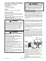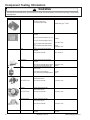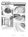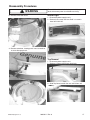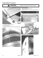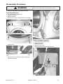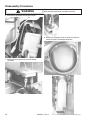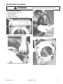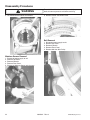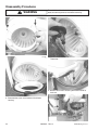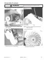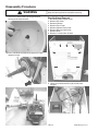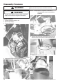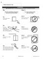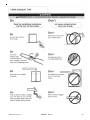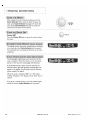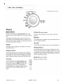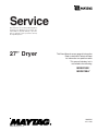
1
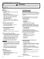
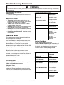
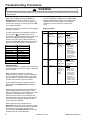
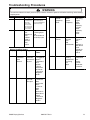
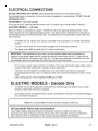
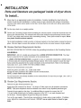
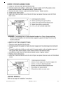
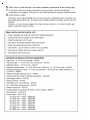
Service
This manual is to be used by qualified appliance
technicians only. Maytag does not assume any
responsibility for property damage or personal
injury for improper service procedures done by
an unqualified person.
27” Dryer
This Base Manual covers general information
Refer to individual Technical Sheet
for information on specific models
This manual includes, but is
not limited to the following:
MDE9700A*
MDG9700A*
16025911
March 2005
©2005 Maytag Services
Important Information
Important Notices for Servicers and Consumers
Maytag will not be responsible for personal injury or property damage from improper service procedures. Pride and
workmanship go into every product to provide our customers with quality products. It is possible, however, that
during its lifetime a product may require service. Products should be serviced only by a qualified service technician
who is familiar with the safety procedures required in the repair and who is equipped with the proper tools, parts,
testing instruments and the appropriate service information. IT IS THE TECHNICIANS RESPONSIBILITY TO
REVIEW ALL APPROPRIATE SERVICE INFORMATION BEFORE BEGINNING REPAIRS.
!
WARNING
To avoid risk of severe personal injury or death, disconnect power before working/servicing on appliance to avoid
electrical shock.
To locate an authorized servicer, please consult your telephone book or the dealer from whom you purchased this
product. For further assistance, please contact:
Customer Service Support Center
CAIR Center
Web Site
Telephone Number
WWW.MAYTAG.COM ............................................. 1-800-688-9900
CAIR Center in Canada ........................................... 1-800-688-2002
Recognize Safety Symbols, Words, and Labels
! DANGER
DANGER—Immediate hazards which WILL result in severe personal injury or death.
!
WARNING
WARNING—Hazards or unsafe practices which COULD result in severe personal injury or death.
!
CAUTION
CAUTION—Hazards or unsafe practices which COULD result in minor personal injury, product or property
damage.
2
16025911 Rev. 0
©2005 Maytag Services
Important Information .................................................... 2
Important Safety Information ......................................... 4
General Information
Model Identification .................................................... 8
Serial Label Location ................................................. 8
Model Nomenclature .................................................. 9
Troubleshooting
Troubleshooting General Symptoms ......................... 10
Component Testing Information
Component Testing Information ................................. 14
Disassembly Procedures
Door Reversal/Disassembly ...................................... 16
Interior Light .............................................................. 17
Top Removal ............................................................. 17
Drum Baffle Removal ................................................. 18
Console Removal ...................................................... 18
Front Panel Removal ................................................. 19
Heater Assembly Removal ........................................ 19
Front Bulkhead Removal ........................................... 21
Moisture Sensor Removal ......................................... 22
Belt Removal ............................................................. 22
Belt Switch Removal ................................................. 23
Drum Removal .......................................................... 23
Motor/Blower Assembly Removal .............................. 32
Rear Bulkhead Removal ............................................ 26
Rear Roller Removal .................................................. 27
Gas Model Disassembly Procedures
Igniter Removal ......................................................... 27
Burner Removal ........................................................ 28
Appendix A
Installation Instructions ............................................. 29
Appendix B
Use And Care ........................................................... 42
©2005 Maytag Services
16025911 Rev. 0
3
Important Safety Information
! WARNING
To avoid risk of fire, electric shock, serious injury, or death when using your dryer, follow these basic precautions:
1. Read all instructions before
using dryer.
2. Install dryer according to
Installation Instructions. Refer to
the Grounding Instructions in the
Installation Instructions for
proper grounding of the dryer.
3. Do not dry articles that have
been cleaned in, washed in,
soaked in, or spotted with
gasoline, dry-cleaning solvents,
or other flammable or explosive
substances. Vapors could ignite
or explode.
4. Do not use dryer to dry clothes
which have traces of any
flammable substance, such as
vegetable oil, cooking oil,
machine oil, flammable
chemicals, thinner, etc., or
anything containing wax or
chemicals, such as mops and
cleaning cloths. Flammable
substances may cause fabric to
catch fire by itself.
5. Do not store or use gasoline or
other flammable vapors and
liquids near this or any other
appliance.
6. Do not allow children to play on
or in dryer. Close supervision of
children is necessary when
dryer is used near children, a
safety rule for all appliances.
7. Before dryer is removed from
service or discarded, remove
doors to drying compartment.
8. Do not reach into dryer if
cylinder is revolving.
9. Do not install or store dryer
where it will be exposed to water
and/or weather.
10. Do not tamper with dryer
controls.
11. Do not repair or replace any part
of dryer or attempt any service,
unless specifically recommended
in user-maintenance instructions
or in published user-repair
instructions that you understand
and have skills to carry out, if you
are a consumer.
12. To reduce risk of electric shock or
fire, do not use extension cords or
adapters to connect dryer to
electrical power source.
13. Use the dryer only for its intended
purpose, drying clothes.
14. Always disconnect dryer from
electrical supply before
attempting any service.
Disconnect power cord by
grasping the plug, not the cord.
15. Do not use heat to dry articles
containing foam rubber or
similarly textured rubberlike
materials.
16. Always clean the lint filter after
every load. A layer of lint in the
filter reduces drying efficiency and
prolongs drying time.
17. Use only fabric softeners or
products to eliminate static that
are appropriate for automatic
dryers.
18. Keep your dryer in good condition.
Bumping or dropping dryer can
damage safety features. If
damage occurs, have dryer
checked by qualified service
technician.
19. Replace worn power cords and/or
loose plugs.
20. Do not tumble fiberglass curtains
and draperies unless the label
says it can be done. If they are
dried, wipe out the cylinder with a
damp cloth to remove particles of
fiberglass.
21. Always read and follow
manufacturer’s instructions on
packages of laundry aids. Heed
all warnings or precautions. To
reduce risk of poisoning or
chemical burns, keep products
away from children at all times,
preferably, in a locked cabinet.
22. Never operate dryer with guards
and/or panels removed.
23. Do not operate dryer with
missing or broken parts.
24. Do not bypass safety devices.
25. Keep area around the exhaust
opening and adjacent
surrounding areas free from
accumulation of lint, dust, and
dirt.
26. Interior of dryer and exhaust duct
should be cleaned periodically
by qualified service personnel.
27. Dryer will not operate with
loading door open. DO NOT
bypass door safety switch by
permitting dryer to operate with
door open. Dryer will stop
tumbling when door is opened.
Do not use dryer if it does not
stop tumbling when door is
opened or starts tumbling
without pressing or turning the
START mechanism. Remove the
dryer from use and call
the service person.
28. Remove laundry immediately
after the dryer stops.
29. ALWAYS follow the fabric care
instructions supplied by the
garment manufacturer.
Save These Instructions
4
16025911 Rev. 0
©2005 Maytag Services
Important Safety Information
Electrical Service Information
Electrical Dryers
• 240 VAC, 60 Hz, 30 Amps,
3–wire or 4–wire installations
Gas Dryers
• 120 VAC, 60 Hz, 15 Amps, 3–wire installations
! WARNING
To reduce the risk of fire and exposure to combustion
gases, the dryer MUST be exhausted to the outdoors.
DO NOT exhaust dryer air into a window well, gas vent,
chimney or enclosed, unventilated area, such as an
attic, wall, ceiling, crawl space under a building or
concealed space of a building.
Gas Dryer Power Supply
About Ground Wires
In the event of an electrical short circuit, a ground wire
reduces the risk of electric shock by providing an escape
wire for the electric current.
Standard accepted color coding for ground wires is green
or green with a yellow stripe.
Grounding wires and wires colored like grounding wires
are NOT to be used as current carrying conductors.
This equipment MUST be grounded. In the event of an
electrical short circuit, grounding reduces the risk of
electric shock by providing an escape wire for the
electrical current. This unit is equipped with a cord
having a grounding wire with a grounding plug. The plug
must be plugged into an outlet that is properly installed
and grounded.
! WARNING
Consult a qualified electrician or servicer if grounding
instructions are not completely understood, or if doubt
exists as to whether the equipment is properly grounded.
To reduce the risk of fire, electric shock, serious injury
or death, all wiring and grounding must conform with
the latest edition of the National Electric Code, or the
Canadian Electrical Code, and such local regulations
as might apply. It is the customer’s responsibility to
have the wiring and fuses checked by a qualified
electrician to make sure your home has adequate
electrical power to operate the dryer.
Do not use an extension cord. If the product power cord
is too short, have a qualified electrician install a three–
slot receptacle. This unit should be plugged into a
separate 60 hertz circuit with the electrical rating as
shown on the serial plate.
! WARNING
To avoid risk of personal injury or death due to
electrical shock:
•
•
•
•
•
•
•
•
•
•
•
Observe all local codes and ordinances.
Disconnect electrical power to unit before servicing.
Ground appliance properly.
Check with a qualified electrician if you are not sure
this appliance is properly grounded.
DO NOT ground to gas line.
DO NOT ground to cold water pipe if pipe is
interrupted by plastic, nonmetallic gaskets, or other
insulating (nonconducting) materials.
DO NOT modify plug on power cord. If plug does not
fit electrical outlet, have proper outlet installed
by qualified electrician.
DO NOT have a fuse in the neutral or ground circuit.
A fuse in the neutral or ground circuit could result in
an electrical shock.
DO NOT use an extension cord with this appliance.
DO NOT use an adapter plug with this appliance.
DO NOT pinch power cord.
©2005 Maytag Services
Proper Grounding and Polarization for 120 Volts
Wall Outlets
For the safety of our customers and the service technician ALL Amana gas dryers have a three–prong power
cord and MUST be connected to a properly polarized and
grounded wall outlet. This information was written for
those who do not understand grounding and polarization
of a wall outlet. A 120 VAC wall outlet must always be
wired as shown below.
Ground
Neutral
L1
Neutral
side
0
V.A.C.
115–12
V.A.C.
Round
grounding
prong
115–12
V.A.C.
Explanation
Polarization–This means that the larger slot must be
neutral and the small slot must be hot (live).
Mispolarized–The outlet is miswired so that the larger
slot is hot (live) and the smaller slot is neutral.
Grounded–This means the round hole connection is
connected to ground through a connection to the main
power panel.
Ungrounded–The round hole connection is not
connected to a ground and/or the main power panel.
16025911 Rev. 0
5
Important Safety Information
Gas Connection Information
! WARNING
To avoid death, personal injury or property damage,
from fire or explosion, information in this manual must
be followed exactly.
Do not store or use gasoline or other flammable
vapors and liquids in the vicinity of this or any other
appliance.
WHAT TO DO IF YOU SMELL GAS
• Do not try to light any appliance.
• Do not touch any electrical switch; do not use any
phone in your building.
• Immediately call your gas supplier from a neighbor’s
phone. Follow the gas supplier’s instructions.
• If you cannot reach your gas supplier, call the fire
department.
Installation and service must be performed by a
qualified installer, service agency or the gas supplier.
! WARNING
To reduce the risk of fire and exposure to combustion
gases, the dryer MUST be exhausted to the outdoors.
DO NOT exhaust dryer air into a window well, gas
vent, chimney or enclosed, unventilated area, such as
an attic, wall, ceiling, crawl space under a building or
concealed space of a building.
6
16025911 Rev. 0
©2005 Maytag Services
Important Safety Information
©2005 Maytag Services
16025911 Rev. 0
7
General Information
Service
Model Identification
Complete registration card and promptly return. If
registration card is missing:
• For Maytag product call 1-800-688-9900 or visit the
Web Site at www.maytag.com
• For product in Canada call 1-866-587-2002 or visit the
Web Sites at www.maytag.com or www.jennair.com
When contacting provide product information located on
rating plate. Record the following:
Model Number:
___________________
Manufacturing Number:
___________________
Serial or S/N Number:
___________________
Date of purchase:
___________________
Dealer’s name and address:
___________________
Keep a copy of sales receipt for future reference or in
case warranty service is required. To locate an authorized
servicer:
• For Maytag product call 1-800-462-9824 or visit the
Web Site at www.maytag.com
• For product in Canada call 1-866-587-2002 or visit the
Web Site at www.maytag.com
Warranty service must be performed by an authorized
servicer. We also recommend contacting an authorized
servicer, if service is required after warranty expires.
Parts and Accessories
Purchase replacement parts and accessories over the
phone. To order accessories for your product call:
• For Maytag product call 1-800-462-9824 or visit the
Web Site at www.maytag.com
• For product in Canada call 1-866-587-2002 or visit the
Web Sites at www.maytag.com or www.jennair.com
Extended Service Plan
We offer long-term service protection for this new oven.
• Dependability PlusSM Extended Service Plan is
specially designed to supplement Maytag’s strong
warranty. This plan covers parts, labor, and travel
charges.
Call 1-800-925-2020 for information.
Serial Label is located in the lower center of the door
opening and back panel.
8
16025911 Rev. 0
©2005 Maytag Services
General Information
27” Dryer Nomenclature
M
D
E
9
7
0
0
A
Y
W
Color
Brand
M
W
M
Maytag
Product Type
DE
Dryer Electric
DG
Dryer Gas
Listing
W
Y
Z
Y
120V-60hz
240V-60hz
Canada 240V-60hz
220-240 V / 50-60 Hz
Marketing Code
Feature Content
9700
White
Platinum
This identifies which
version of production the
unit is.
Feature Package
Troubleshooting Guide is Located on the
back of the unit.
©2005 Maytag Services
16025911 Rev. 0
9
Troubleshooting Procedures
!
WARNING
To avoid risk of electrical shock, personal injury or death, disconnect power to unit before servicing, unless testing
requires power.
Place dryer into Service Mode and check for diagnostic codes. See Technical Data Sheet taped to rear
panel.
Will Not Run
Will not start or run:
• All wires are hooked up to their corresponding
terminals.
• Dryer is plugged in.
• Blown fuse or circuit breaker.
• Door switch functional...door closed. Check for
error code 3 (See Table for code definition).
• Start/Pause rotary selector dial functional.
• Control Board operational.
• Drive motor functional.
• Check motor winding resistance: 2.88ohms
between pin #3 and 4, 3.5ohms between pin #4
and 5.
Motor runs/ tumbler will not turn:
• Belt off or broken/damaged.
• Idler tension spring too weak or stretched.
• Idler pulley jammed or stuck.
Runs a few minutes and then stops:
• Lint buildup around drive motor.
• Low voltage present.
• Blower impeller blocked in blower
housing.
• Drive motor - start switch contacts stuck closed.
Blows fuses or trips circuit breaker:
• The amperage readings are at 240 volts. One line
will be 24 amps and the other line will be 21 amps.
The neutral line will be at 3 amps. If the above
amperages are present, then the house wiring,
fuse box or circuit breaker should be suspect.
• Shorted heating element to housing.
• Incorrect wiring or a wire shorting to ground.
• Drive motor winding shorting to ground.
Gas Models
• During ignition the dryer will draw X amps. With the
burner ON, the dryer will draw X amps. If the dryer
is drawing amperages above this, then the house
wiring, fuse box or circuit breaker is suspected to
be at fault.
• Igniter harness loose and shorted to base.
• Incorrect wiring or wire shorted to ground.
• Drive motor winding shorting to ground.
Will Not Dry
Will not heat (motor runs):
• Open heating element.
• Hi-Limit trips easily or is open.
• Regulating thermostat trips easily or is open.
• Membrane switch open.
• Check Thermistor.
10
Will Not Dry Gas Models
Poor Gas Ignition
When the dryer is operated on a heat setting, the
igniter should be energized and burner shall fire within
45 seconds at 120 VAC. The failure of a component in
this system will usually be indicated by one of three
symptoms:
The igniter does not glow. If the igniter does not
heat up, remove power and using an ohmmeter,
check the following:
• Open flame sensor
• Open igniter
• Shorted booster coil
• Open wiring
• Bad motor switch ( Neutral supply)
• No power from control ( L1 supply)
Igniter glows - No gas ignition. If the igniter heats
up but the main burner flame is not ignited, remove
power and using an ohmmeter, check the following:
• Open secondary coil
• Open holding coil
• Open wire harness
• Stuck flame sensor (Stuck closed)
The gas is ignited but the flame goes out. If a
normal ignition takes place and after a short while the
flame goes out, check for the following:
• Radiant sensor contacts opening
prematurely.
• Weak gas valve coil may open when
stressed by higher temperatures.
• Weak Hi-Limit
• Poor venting
•
Bad drum seals
Improper drying/clothes wrinkled/ rough
texture/long dry time:
• Lint filter is not clean.
• Restriction in exhaust.
• Outside exhaust hood damper door stuck closed.
• Exhaust too long, too many elbows, flex ductwork
installed.
• Poor intake air available for the dryer.
• Incorrect tumbler speed. Tumbler belt slipping.
• Blower impeller bound; check for foreign material
in blower area.
• Customer overloading dryer.
• Check clothing labels for fabric content and cycle
selected.
• Clothes too wet due to insufficient spin out by
washer.
Will Not Shut Off
• Check Membrane Pad.
16025911 Rev. 0
©2005 Maytag Services
Troubleshooting Procedures
!
WARNING
To avoid risk of electrical shock, personal injury or death, disconnect power to unit before servicing, unless testing
requires power.
Troubleshooting the electronic
control circuit:
• Check for miswiring of the electrical connector at
the electronic control board.
Noisy and/Or Vibration
• Thumping Check for loose tumbler baffle, rear
tumbler roller(s) worn or misaligned, out-of-round
tumbler or high weld seam on tumbler.
• Ticking Check for loose wire harness or object
caught in blower wheel area.
• Scraping Check for front or rear bulkhead felt seal
out of position or worn tumbler front bearings.
• Roaring Check for blower wheel rubbing on blower
housing or bad motor bearings.
• Popping or squealing sound. Check for a sticky
or frayed belt.
Press the following keys to access:
Key Press
Special
Test/Function
Display list of
Wrinkle Prevent
diagnostic codes.
Displays “d”
Then rotate the Cycle
Selector Knob
To sequence thru
the diagnostic
and help codes.
Temperature Key
Display software
revision number
Start/Pause
Service Mode
This mode provides Service Personnel the ability to
verify the operation of the dryer.
The Service Mode can be implemented at any time,
including the middle of a dry cycle. While in the
Service Mode, the Technician can start special
diagnostic tests such as a System Check Mode, LED
Switch/Check, Display Software version number and
display diagnostic/help code listings.
Enter Service Mode:
Dryer must be on before Service Mode can be
entered. Press Chime and Temperature Keys for 3
seconds, or until 3 beeps are heard. The machine will
now be in Service Mode. Upon entry into Service
Mode, the Sensor Bar Touch
Data is to be displayed.
Exit Service Mode
Press the OFF key to exit Service Mode or repeat the
Chime and Temperature sequence.
Diagnostic Tests
The following table lists the various tests available
while in the Service Mode. Before advancing to the
next test, the current test running must be terminated.
©2005 Maytag Services
Start or pause
cycle running but
remain in
diagnostic mode.
Display the
number of cycles
ago the
diagnostic code
occurred.
System Check Mode
While in Service Mode, pressing the
Time and Wrinkle Prevent keys for 3 seconds, will
put the dryer into the System Check mode and "in"
will display. The following table lists the various
functions based on the keys being pressed.
System Check Mode Table
Key Pressed:
Start/Pause rotary
selector dial
Rotate the Cycle Selector
Knob to Delicates
Rotate the Cycle Selector
Knob to Sensor
Dry
Function
Performed
Cycles the motor
on/off.
LED’s and 7
segment display
flash.
View current
cycle temperature
in Celsius.
Rotate the Cycle Selector
Knob to Wrinkle Control
Segment display
is “1” for sensor
bar short, “0” for
sensor bar open
Rotate the Cycle Selector
Knob to Time Dry
View current
cycle
temperature in
Fahrenheit.
16025911 Rev. 0
11
Troubleshooting Procedures
!
WARNING
To avoid risk of electrical shock, personal injury or death, disconnect power to unit before servicing, unless testing
requires power.
LED/Switch Check
While in Service Mode, pressing the Chime and
Wrinkle Prevent keys for 3 seconds, will start a
LED/Switch Test. To exit the test at any point, press
the same keys again for 3 seconds or press the OFF
key to exit Service Mode.
Clearing Diagnostic Codes
To clear the diagnostic code list press the Sensor Dry
Level and Time keypads together for 3 seconds while
viewing the list. The cycle count for each diagnostic
code will be reset to 0, but not the machine cycle
count.
Perform the check by pressing the keys, which toggle
the LED’s on and off.
Diagnostic Codes
All switch pads must be pressed within 5 minutes for
this test to pass. PA will be displayed for five (5)
seconds once all switch pads have been pressed and
this test is completed. Following 10 seconds of
inactivity at any point, the test will exit without any
display. The Power Off switch pad must be pressed
twice within thirty (30) seconds to cancel this test.
Switch
Action
Wrinkle Prevent
Chime
Adjust Time
Time
Temperature
Dryness Level
Selector Knob
Start Pause
Off
Press once
Press twice
Press once
Press four times
Press three times
Press four times
Rotate 1 position
Press once
Press once
Code
1
2
Trigger
Action Taken
Dryer
Thermistor
Short Sensed
Description
The
Thermistor
resistance is
very low.
Thermistor
Open Sensed
The
Thermistor
resistance is
very high
Check for:
- Clogged lint
screen.
- Restricted vent
system.
- Check Thermistor
resistance.
Check for:
- Low ambient
temperature in
room (Below
º
º
50 F/10 C).
Outside vent
damper is stuck
open in wintertime.
- Loose or open
wire terminals.
- Check Thermistor
resistance.
Check for:
- Loose or open
wire terminals in
Door Sense
circuit.
Check for:
- Loose connections
in motor circuit.
- Run System
Check Mode and
check the motor
relay function.
- If relay functions,
disregard the
diagnostic code.
- If relay does not
function, replace
machine control
board.
-
Diagnostic Codes
The Diagnostic Codes are identified when the severity
level of the abnormality detected is higher and service
may be required.
3
Door Circuit
Failure
Invalid state
for more
than 256
milliseconds
4
Possible motor
transistor error
If either
motor
transistor is
seen open or
shorted
during
startup
When a problem with the dryer is detected a
Diagnostic Code is assigned, and can be displayed.
The Control Board will not log multiple same codes
per cycle; however, it will log as many Diagnostics as
possible for the machine to continue running.
Access Diagnostic Codes by entering the Service
Mode and pressing Wrinkle Prevent. A d will be
displayed.
Rotate the Cycle Selector Knob in either direction to
step through the list of codes one code at a time.
Once an initial direction is selected by the user (either
Clockwise or Counterclockwise), subsequent
movements of the knob in the same direction will
show older codes. If the user changes direction and
turns the knob in the opposite direction, the more
recent code will be displayed.
While a diagnostic code is displayed, if the
Start/Pause button in the center of the Rotary Cycle
Selector is pressed and held, the machine will display
the number of cycles ago the diagnostic code
occurred. When the Start/Pause button is released,
the diagnostic code is again displayed.
12
16025911 Rev. 0
©2005 Maytag Services
Troubleshooting Procedures
!
WARNING
To avoid risk of electrical shock, personal injury or death, disconnect power to unit before servicing, unless testing
requires power.
Code
8
10
Description
Trigger
Action Taken
Stuck Key
A key is
sensed to be
pressed
more than
75 seconds,
the key shall
be assumed
to be stuck.
Run membrane pad
check and replace
console w/membrane
pad if necessary.
No Wet Clothes
Sensor
bar
detects no
wet
clothes
while a
Sensor
Dry
Cycle
Check for:
- Running dryer
with
no wet clothes in
sensor dry cycle
Display Fault/Error Codes
Display Description Trigger
Power
source
frequency
Error
Invalid
power
source
Frequency
Check for:
- Not using
regular
power
source
frequency
- Invalid
power
frequency
sense
circuit
dC
Door Circuit
Failure
Invalid state
for more
than
256
milliseconds
Check for:
- Loose or
open
wire
terminals in
Door Sense
circuit.
- Check for
diagnostic
code 3
hE
Heater Error
Invalid
heating
temperature
in running
the
dryer
Check for:
- Restricted
vent
system.
- Check
Thermistor
resistance.
Action
Taken
tS
Dryer
Thermistor
Short
Sensed
The
Thermistor
resistance is
very low.
Check for:
- Clogged lint
screen.
- Restricted
vent
system.
- Check
Thermistor
resistance.
- Check for
diagnostic
code 1
do
Door Open
Running the
dryer with
door open
Check for:
- Close the
door,
and run the
dryer
- Loose or
open
wire
terminals in
Door Sense
circuit.
- Check for
diagnostic
code 3
©2005 Maytag Services
FE
16025911 Rev. 0
13
Component Testing Information
!
WARNING
To avoid risk of electrical shock, personal injury or death, disconnect power to unit before servicing, unless testing
requires power.
Illustration
Component
Thermistor
Door Switch
Light
Belt Switch
Motor
Thermostat
185°F/85°C 25A
Hi Limit
210°F/99°C 25A
Thermal Cut Off
Heater Element
14
Test Procedure
Unplug harness connector and test
from wire insertion side.
Pin #2 and Pin #6 of CN6
Results
10000 ohms @ 77° F/25°C
Unplug connectors and test switch
terminals.
Door open terminals COM to NC/ 1 to
3
Door open terminals COM to NO/1 to
2
Door closed terminals COM to NC/ 1
to 3
Door closed terminals COM to NO/ 1
to 2
Unplug connectors and test switch
terminals.
Infinity
Check across terminals
80 to 100 ohms
Less than 1 ohm
Infinity
Less than 1 ohm
Unplug connectors and test switch
terminals.
Check across terminals switch closed
Check across terminals switch open
Unplug harness connector and test
motor circuits.
Less than 1 ohm
Infinity
Pin #4 and Pin #5 (Windings)
Pin #1 and Pin #2 (Centrifugal switch)
2 ohms
Open
Unplug connectors and test
Thermostat terminals.
Check across terminals
Less than 1 ohm
Unplug connectors and test
Thermostat terminals.
Check across terminals
Less than 1 ohm
Unplug connectors and test
Thermostat terminals.
Check across terminals
Less than 1 ohm
Unplug connectors and test Heater
terminals
10 ohms
16025911 Rev. 0
©2005 Maytag Services
Component Testing Information
!
WARNING
To avoid risk of electrical shock, personal injury or death, disconnect power to unit before servicing, unless testing
requires power.
Illustration
Component
Sensor Bars
Test Procedure
Unplug harness connector and test
from wire insertion side.
Pin #4 to Pin # 5 of CN6
Results
Infinity dry load 190ohms ± 10% wet
load
Radiant Sensor
Unplug connectors and test sensor
terminals.
Closed
TH2 Safety
Thermostat
Unplug connectors and test
Thermostat terminals.
Less than 1ohm
Gas Valve
Unplug connectors and test valve
terminals.
Check across terminals #1 and #3
(Booster Coil).
Check across terminals #1 and #2
(Holding Coil).
Check across terminals #2 and #3
(Both coils in series). Check across
terminals #4 and #5 (Secondary Coil).
550ohms
1350ohms
1900ohms
1300ohms
Motor Contacts
Gas Valve
Function
Start
Run
1M
2M
3M
5M
6M
= Contact closed
Centrifugal Switch (Motor)
123
©2005 Maytag Services
16025911 Rev. 0
45
15
Disassembly Procedures
!
To avoid risk of electrical shock, personal injury or
death; disconnect power to unit before servicing.
WARNING
Door Reversal/Disassembly
1. Disconnect power supply to unit.
2. Remove four screws and Door Strike.
6. Remove Inner Panel.
3. Remove two screws attaching Door Hinge.
7. Remove Gasket.
4. Install Door and Strike on opposite sides or continue
with Door disassembly.
5. Remove screws around perimeter of Door Inner
Panel.
16
16025911 Rev. 0
©2005 Maytag Services
Disassembly Procedures
!
To avoid risk of electrical shock, personal injury or
death; disconnect power to unit before servicing.
WARNING
Interior Light
8. Remove Inner Door Glass.
1. Disconnect power supply to unit.
2. Remove Lens screw and Lens. Bulb is a screw in
base 10W 120V AC.
9. Remove outer door viewing panel. Insert screwdriver
in slot to disengage latch.
Top Removal
1. Disconnect power supply to unit.
2. Remove 2 10mm screws from dryer back.
3. Slide Top Cover towards the rear and lift from unit.
©2005 Maytag Services
16025911 Rev. 0
17
Disassembly Procedures
!
To avoid risk of electrical shock, personal injury or
death; disconnect power to unit before servicing.
WARNING
Console Removal
1. Disconnect power supply to unit.
2. Remove Top Cover.
3. Remove two screws mounting the Heater PCB Board.
4. Disconnect the black and white connectors.
Drum Baffle Removal
1. Disconnect power supply to unit.
2. Remove Top Cover.
3. Remove four screws located at the sound dampening
seem.
5. Remove four screws attaching Console to washer.
18
16025911 Rev. 0
©2005 Maytag Services
Disassembly Procedures
!
To avoid risk of electrical shock, personal injury or
death; disconnect power to unit before servicing.
WARNING
6. Rotate Console down and remove from dryer.
Front Panel Removal
1.
2.
3.
4.
Disconnect power supply to unit.
Remove Top Cover.
Remove Console.
Remove four screws attaching Front Panel to dryer.
5. Remove two screws in the door area.
Heater Assembly Removal
6. Pull Front Panel forward and disconnect the Interior
Light harness.
1.
2.
3.
4.
5.
Disconnect power supply to unit.
Remove Top Cover.
Remove Console.
Remove Front Cover.
Remove Heater Assembly retaining screw.
7. Lift the Front Panel off the three tabs across the
bottom and remove.
©2005 Maytag Services
16025911 Rev. 0
19
Disassembly Procedures
!
WARNING
To avoid risk of electrical shock, personal injury or
death; disconnect power to unit before servicing.
6. Slide Heater Assembly out the front of dryer..
8. Reinstall by aligning the tabs on the back bulkhead
with the notches in the Heater Assembly .
7. Remove the wiring terminals from the Heater
Assembly.
20
16025911 Rev. 0
©2005 Maytag Services
Disassembly Procedures
!
To avoid risk of electrical shock, personal injury or
death; disconnect power to unit before servicing.
WARNING
Front Bulkhead Removal
1.
2.
3.
4.
5.
Disconnect power supply to unit.
Remove Top Cover.
Remove Console.
Remove Front Panel.
Remove screws retaining Console Back Cover.
6. Disconnect Interior Light wiring harness.
8. Remove four Bulkhead retaining screws
7. Disconnect Moisture Sensor wiring harness.
©2005 Maytag Services
16025911 Rev. 0
21
Disassembly Procedures
!
WARNING
9. Lift Bulkhead from Cabinet and remove.
To avoid risk of electrical shock, personal injury or
death; disconnect power to unit before servicing.
6. Remove sensor attachment screw.
Belt Removal
1.
2.
3.
4.
5.
Disconnect power supply to unit.
Remove Top Cover.
Remove Console.
Remove Front Panel.
Remove belt from Idler Pulley
Moisture Sensor Removal
1.
2.
3.
4.
5.
22
Disconnect power supply to unit.
Remove Top Cover.
Remove Console.
Remove Front Panel.
Disconnect Moisture Sensor wire harness.
16025911 Rev. 0
©2005 Maytag Services
Disassembly Procedures
!
To avoid risk of electrical shock, personal injury or
death; disconnect power to unit before servicing.
WARNING
Drum Removal
1.
2.
3.
4.
5.
6.
7.
8.
Pull Idler
Pulley
Disconnect power supply to unit.
Remove Top Cover.
Remove Console.
Remove Front Panel.
Remove Console Back Cover.
Remove Front Bulkhead.
Remove belt from Idler Pulley.
Grasp the Drum with one hand and the belt with the
other. Lift the Drum and slide out the front. Carefully
spread the cabinet as needed to gain additional
clearance.
Belt Switch Removal
1. Disconnect power supply to unit.
2. Remove five screws retaining Vent Tube cover.
3. Remove Belt Switch mounting screw.
Motor/Blower Assembly Removal
1.
2.
3.
4.
5.
6.
7.
8.
Disconnect power supply to unit.
Remove Top Cover.
Remove Console.
Remove Front Panel.
Remove Console Back Cover.
Remove Belt from Idler Pulley.
Remove Drum.
Remove the two screws securing the Blower Intake
Panel to the Blower Housing. Remove Blower Intake
Panel.
Belt
Switch
©2005 Maytag Services
16025911 Rev. 0
23
Disassembly Procedures
!
To avoid risk of electrical shock, personal injury or
death; disconnect power to unit before servicing.
WARNING
10.Remove the blower attachment screw under the
Thermistor.
11. Remove two screws attaching the motor bracket to
the base.
9. Removed the screw at the bottom of the blower
housing.
24
16025911 Rev. 0
©2005 Maytag Services
Disassembly Procedures
!
To avoid risk of electrical shock, personal injury or
death; disconnect power to unit before servicing.
WARNING
12.Disconnect the Motor wire harness and the two wires
to the belt switch.
13.Slide the Motor Blower Assembly toward the heater
and lift to disengage the tabs on the motor from the
slots in the base.
NOTE: A wrench can be placed on both ends of the
Motor Output Shaft.
15.Remove Blower Wheel.
14.Remove the 14mm nut securing the blower wheel to
the shaft. The nut is a left hand thread.
©2005 Maytag Services
16.Remove the three screws securing the blower
housing to the motor bracket.
16025911 Rev. 0
25
Disassembly Procedures
!
To avoid risk of electrical shock, personal injury or
death; disconnect power to unit before servicing.
WARNING
17.Remove the three screws securing the blower
housing to the motor bracket .
Rear Bulkhead Removal
1.
2.
3.
4.
5.
6.
7.
8.
Disconnect power supply to unit.
Remove Top Cover.
Remove Console.
Remove Front Panel.
Remove Console Back Cover.
Remove Belt from Idler Pulley.
Remove Drum.
Remove 7 screws from the back.
18.Use a wide blade screwdriver to pop off the motor
retention clamps.
9. Lift the rear bulkhead off the right and left side
hangers.
26
16025911 Rev. 0
©2005 Maytag Services
Disassembly Procedures
!
WARNING
To avoid risk of electrical shock, personal injury or
death; disconnect power to unit before servicing.
Rear Roller Removal
1. Disconnect power supply to unit.
2. Remove Rear Bulkhead.
3. Remove Roller Keeper and nut.
Gas Model Disassembly
Igniter Removal
1.
2.
3.
4.
5.
©2005 Maytag Services
Disconnect power supply to unit.
Remove Top Cover.
Remove Console.
Remove Front Panel.
Loosen the single screw attaching the igniter to the
Burner Assembly. Slide the Igniter back and remove.
16025911 Rev. 0
27
Disassembly Procedures
!
To avoid risk of electrical shock, personal injury or
death; disconnect power to unit before servicing.
WARNING
! WARNING
To avoid risk of personal injury or death; shut off gas
supply to unit before servicing Burner Assembly.
NOTE: The Igniter Bar is fragile. Be careful not to
damage Igniter when removing Burner
Assembly.
Burner Removal
1. Disconnect power supply to unit.
2. Shut off gas supply.
3. Disconnect gas line.
5. Remove the two screws attaching the housing to the
burner bracket. The screws are recessed from view.
6. Slide Burner Assembly from dryer.
4. Remove two screws securing burner to bracket.
28
16025911 Rev. 0
©2005 Maytag Services
Appendix A
©2005 Maytag Services
16025911 Rev. 0
29
30
16025911 Rev. 0
©2005 Maytag Services
©2005 Maytag Services
16025911 Rev. 0
31
32
16025911 Rev. 0
©2005 Maytag Services
©2005 Maytag Services
16025911 Rev. 0
33
34
16025911 Rev. 0
©2005 Maytag Services
©2005 Maytag Services
16025911 Rev. 0
35
36
16025911 Rev. 0
©2005 Maytag Services
©2005 Maytag Services
16025911 Rev. 0
37
38
16025911 Rev. 0
©2005 Maytag Services
©2005 Maytag Services
16025911 Rev. 0
39
40
16025911 Rev. 0
©2005 Maytag Services
©2005 Maytag Services
16025911 Rev. 0
41
Appendix B
42
16025911 Rev. 0
©2005 Maytag Services
©2005 Maytag Services
16025911 Rev. 0
43
44
16025911 Rev. 0
©2005 Maytag Services
©2005 Maytag Services
16025911 Rev. 0
45
46
16025911 Rev. 0
©2005 Maytag Services
©2005 Maytag Services
16025911 Rev. 0
47
48
16025911 Rev. 0
©2005 Maytag Services
©2005 Maytag Services
16025911 Rev. 0
49
50
16025911 Rev. 0
©2005 Maytag Services
©2005 Maytag Services
16025911 Rev. 0
51
52
16025911 Rev. 0
©2005 Maytag Services
©2005 Maytag Services
16025911 Rev. 0
53
54
16025911 Rev. 0
©2005 Maytag Services
©2005 Maytag Services
16025911 Rev. 0
55
56
16025911 Rev. 0
©2005 Maytag Services
©2005 Maytag Services
16025911 Rev. 0
57
58
16025911 Rev. 0
©2005 Maytag Services