1
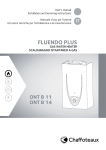
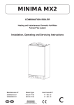
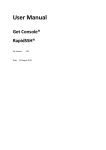
NEXT
User manual
Installation and Servicing instructions
Important: This appliance is a domestic gas fired hot water heater and is intended for domestic use only
INSTANTANEOUS MULTIPOINT GAS
WATER HEATER
TYPE C
NEXT SFT 14
Country of destination GB, IE
User manual
1. General warnings ....................................................3
1.1. CE labelling .....................................................3
1.2. Safety regulations ...........................................3
2 User instructions. ....................................................4
2.1. Control panel...................................................4
2.1.2. Display .....................................................4
2.2. Initial set-up
2.3 Ignition procedure ...........................................5
2.4 Water temperature adjustment ......................5
2.5 Bath Function .................................................5
2.6 Switchinf off procedure ...................................6
2.7 Appliance shut-off conditions .........................6
2.8 Anti-freeze protection .....................................6
2.9. Change gas type ..............................................7
2.10. Maintenance ....................................................7
1. general information
1. GENERAL INFORMATION
The Next SFT Water Heater is a room sealed, fanned flue,
mulitpoint water heater.
The appliance has been designed for domestic use only and
to be connected to a mains cold water supply with a minimum
pressure of 0.5 bar.
A permanent electrical connection is required and should
be provided by use of a fused spur. The electrical supply
should be via a double pole isolating switch with 3mm contact
separation in both poles.
If the appliance is installed in a bathroom the fused spur must
be located externally to the bathroom.
NOTE: Under the gas safety and use regs 1984, it is the law
that all gas appliances are installed by a Gas Safe Registered
Engineer.
Failure to install the appliance in accordance with all current
regulations will result in the guarantee becoming void.
In hard water areas the use of a scale reducer is recommended.
See 3.8.2
Guarantee
The guarantee on this appliance is valid for 12 months from
the date of installation, provided it has been installed in
accordance with this manual, with all current regulations and
used solely for the purpose described in this manual.
Failure to comply with this will result in the guarantee
becoming void.
Warning!!
Water with a temperature higher than
50° cause serious burns.
Always verify water temperature before
use.
Warning!!
The device must be activated only in
presence of water in the exchanger.
1.1. CE labelling
The CE mark guarantees that the appliance conforms to
the following directives:
- 2009/142/CEE relating to gas appliances
- 2004/108/EC relating to electromagnetic
compatibility
- 2006/95/EC relating to electrical safety
1.2. Safety regulations
Key to symbols:
Failure to comply with this warning implies the risk of
personal injury, in some circumstances even fatal
Failure to comply with this warning implies the risk
of damage, in some circumstances even serious, to
property, plants or animals.
Do not perform operations which involve opening the
appliance.
Electrocution from live components.
Personal injury caused by burns due to overheated
components, or wounds caused by sharp edges or
protrusions.
Do not perform operations which involve removing the
appliance from its installation space .
Electrocution from live components.
Flooding caused by water leaking from disconnected piping.
Explosions, fires or intoxication caused by gas leaking from
disconnected piping.
Do not damage the power supply cable.
Electrocution from live uninsulated wires.
Do not leave anything on top of the appliance.
Personal injury caused by an object falling off the appliance
as a result of vibrations.
Damage to the appliance or items underneath it caused by
the object falling off as a result of vibrations.
Do not climb onto the appliance.
Personal injury caused by the appliance falling.
Damage to the appliance or any objects underneath it
caused by the appliance falling away from its installation
space.
Do not climb onto chairs, stools, ladders or unstable
supports to clean the appliance.
Personal injury caused by falling from a height or cuts
(stepladders shutting accidentally).
Do not attempt to clean the appliance without first
switching it off and turning the external switch to the OFF
position.
Electrocution from live components.
Do not use insecticides, solvents or aggressive detergents
to clean the appliance.
Damage to plastic and painted parts.
Do not use the appliance for any use other than normal
domestic use.
Damage to the appliance caused by operation overload.
Damage caused to objects treated inappropriately.
Do not allow children or inexperienced individuals to
operate the appliance.
Damage to the appliance caused by improper use.
If you detect a smell of burning or smoke coming from
the appliance, disconnect it from the electricity supply,
turn off the main gas valve, open all windows and call for
assistance.
Personal injury caused by burns, smoke inhalation,
intoxication.
If there is a strong smell of gas, turn off the main gas valve,
open all windows and call for assistance.
Explosions, fires or intoxication.
This appliance is not intended for use by persons
(including children) with reduced physical, sensory
or mental capabilities, or lack of experience and
knowledge, unless they have been given supervision or
instruction concerning use of the appliance by a person
responsible for their safety.
Children should be supervised to ensure that they do
not play with the appliance.
3
2. user instructions
2. Users Instructions
2.1. Control Panel
5
1
4
2
3
Legend:
1.
Bath button
2.
ON/OFF button
3 & 4. Temperature Buttons( Used to select hot
water delivery temperature.
5.
Display
2.1.2. Display
- Water temperature indication (°C)
- Signal error codes
Water demand in progress
Flame presence signal
Fan active
The display visualises the set
temperature
Reset procedure in progress
Air pressure switch error (see 5.1)
4
2. user instructions
2.2. Initial Set-Up
IMPORTANT:
The installing technician should explain to the user how the
water heater works, the safety devices it includes and how to
use it.
Before turning the water heater on, it should be connected
to the electrical mains via a double pole isolating switch with
3mm contact separation in both poles.
• Make sure that gas is supplied to the water heater (valve on
gas pipe open) and purge any air as necessary
• Make sure that the electrical supply is turned on.
2.4. Water temperature adjustment
Press keys 3 and 4 to set the hot water temperature.
The new value will be indicated on the display
2.3. Ignition procedure
-
ensure that the isolation valve located on the cold water
inlet is open
ensure that the gas isolation valve is open
ensure that the electrical supply is turned on.
When pressing ON/OFF button “2”, the display activates.
It’s possible to increase the temperature up to 48 °C.
To select higher temperatures (50,55,60,65) push button “4”
for few seconds. The display shows 50 °C, by pressing button
“4” again the temperature is increased (in steps of 5 C) up to
a maximum of 65 °C.
WARNING!!!
The factory set temperature is 42°C.
Pay attention when adjusting water temperature higher than
50°C, burns may occur during the draw off phase.
2.5. Bath Function
The appliance is ready to operate
The set temperature is indicated on the display.
The Bath function can be used to specify an amount of hot
water to be dispensed at a selected temperature.
While the appliance is in standby, press the Bath button; 10
(x10L) will appear on the display = 100 litres.
Use buttons 3 and 4 to set the amount, from a minimum of 1
(10 litres) to a maximum of 99 (990 litres).
Press the Bath button to memorise this amount.
The selected temperature appears on the display and can be
adjusted, if necessary, using buttons 3 and 4.
Press the Bath button (1) to store the selected temperature.
The
symbol flashes while the amount and temperature
values are being set.
By opening a hot water tap, the appliance automatically starts
operating.
The display shows the effective temperature and the flame
indicates the burner ignition.
Warning!!
Water with a temperature higher than 50°C can
cause serious burns.
Always verify water temperature before use.
Note: If the device does not operate, ensure that the gas and/
or cold water isolation valves are open.
Ensure that the appliance is electrically powered.
When closing the tap, the appliance automatically switches off
and the flame symbol disappears from the display.
Function activation is indicated by the
symbol.
The hot water request activates
litre metering; the count can be
viewed on the display.
The temperature can also
be adjusted while it is being
dispensed.
The selected temperature and
the dispensed litre count flash
alternately on the display.
The appliance will emit a noise to
indicate that the set litre value has almost been reached:
- 5 litres from the set value by means of an intermittent
sound
- 1 litre from the set value by means of a continuous sound.
When the set amount has been reached, the sound stops and
the appliance reverts to the temperature selected before the
Bath function was activated.
If the request stops before the set amount is reached, the
function is deactivated.
The function can be deactivated by pressing the Bath button
twice.
The function is deactivated within 3 minutes if no requests are
made.
NOTE: THE LITRE METERING CANNOT BE ACCURATE TO THE EXACT LITRE, AND IS
ONLY INTENDED AS AN INDICATIVE MEASUREMENT.
5
2. user instructions
2.6. Switching off procedure
2.7. Appliance shut-off conditions
Press the ON/OFF button “2”, to switch off the appliance.
The display indicates only two hyphens.
To switch off the device completely, turn the external electric
switch off and close the gas isolation valve.
The appliance is protected from malfunctions by means of
internal checks performed by the electronic P.C.B., which
stops the appliance from operating if necessary.
In case of shut-off, the flame symbol disappears from the
display, which indicates an error code – see table below.
To reset the appliance, hold down the ON/OFF button and
release when the word RESET appears.
Should the error signal persist, switch off the appliance, close
the gas isolation valve, turn the external electric switch off
and contact a qualified technician.
Error code table
Error
code
Description
After pressing the ON/OFF key,
the control board switches off
- Ensure that the
device is electrically
powered.
A 1
- Ensure that the gas
isolation valve is open
- Hold down the ON
/ OFF button. The
appliance starts the
RESET procedure.
Release the button
as soon as the RESET
message appears.
No flame detected
Should the error code be not indicated in the table, close the
gas isolation valve, turn the external electrical switch off
and contact a qualified technician.
SHOULD THE ERROR NOT BE ELIMINATED, DO NOT ACTIVATE
THE APPLIANCE.
2.8 Anti-freeze protection
Should the appliance be installed where pipes are subjected
to freezing, it is recommended to empty it.
Proceed as indicated below:
- Turn the outer electrical switch to the OFF position
- Close the gas isolation valve
- Close the cold water inlet isolation valve
- Open the DHW taps until both the appliance and pipes are
completely emptied.
To fill the appliance again, open the cold water inlet isolation
valve together with DHW taps until water flows steadily from
all taps.
6
2. user instructions
7
Installation and servicing instructions
(Only for Gas Safe Registered Engineers)
3. Installation ...............................................................9
3.1. Description of the appliance ...........................9
3.2. Safety regulations .........................................10
3.3. Technical specifications ................................11
3.4. Operating principle .......................................12
3.5. Electrical circuit diagram .............................12
3.6. Appliance dimensions ...................................13
3.7. Minimum clearances ....................................13
3.8. Reference standards .....................................14
3.8.1. Flue ........................................................14
3.8.2. Installing the water heater ....................15
3.8.3. Siting the appliance ...............................15
3.8.4. Gas supply..............................................15
3.8.5. Air supply ...............................................15
3.8.6. Electrical supply ....................................15
3.8.7. Removing the outer casing ....................15
3.8.8. Wall mounting........................................16
3.8.9. Connecting the heater to the water
and gas supply .......................................16
3.8.10. Sealing the water and gas circuits ........16
3.8.11. Connecting the water heater to
the electrical mains ...............................16
3.8.12. Purging the gas supply ..........................16
3.8.13. Completion after commissioning ..........16
3.9. Fitting the flue ...............................................17
3.9.1. Fitting the coaxial flue
(Ø 60/100 Horizontal) .............................18
3.9.2. Flue extensions......................................18
3.9.3. Table of flue gas exhaust duct lengths ..18
3.9.4. Fitting the Coaxial Flue
(Ø 60/100 Vertical) .................................18
4. Commissioning ......................................................19
4.1. Gas supply installation ..................................19
4.2. Checking electricity supply ...........................19
4.3. Lighting the appliance ..................................19
4.4. Setting the gas pressure ...............................19
4.4.1. Supply pressure check ..........................19
4.4.2. Checking the maximum pressure .........19
4.4.3. Checking the minimum pressure ..........20
4.4.4 Completion.............................................20
4.5. Gas settings table .........................................20
4.6. Changing the type of gas ..............................20
5. Appliance shut-off conditions ...............................21
5.1. Table summarising error codes....................21
6. Maintenances .........................................................22
6.1. Servicing instructions ...................................22
6.1.1 Replacement of parts ............................22
6.1.2 To gain general access ..........................22
6.1.3 Removing the air pressure switch.........23
6.1.4 Removing the fan ...................................23
6.1.5 Removing the gas collector ...................24
6.1.6 Removing the ignitor .............................24
6.1.7 Removing the ignition electrode ...........25
6.1.8 Removing the detection electrode ........25
6.1.9 Removing the overheat thermostat ......26
6.1.10 Removing the hot water temp. probe ....26
6.1.11 Removing the inlet water temp. probe ..27
6.1.12 Removing the water flow switch ...........27
6.1.13 Removing the inleft water filter ............28
6.1.14 Removing the main PCB........................28
6.1.15 Removing the display PCB ....................29
6.1.16 Removing the gas valve .........................30
6.1.17 Removing the heat exchanger ...............30
6.2. Fault finding chart .........................................22
6.3. Short spares list ............................................22
7. Terms and conditions of guarantee ..........................
3. installation
3.1. Description of the Appliance
NEXT SFT water heaters are room sealed instantaneous gas
fired water heaters, with electronic ignition and ionisation
safety devices, they have a modulating burner and are
connected to the mains water supply; they provide domestic
hot water.
Their self-contained combustion chambers with fans for
the intake of external air and the extraction of combustion
products, allow them to operate totally independently from
the room in which they are installed.
1
Legend
2
3
18
17
16
4
5
15
14
6
7
13
12
1.
2.
3.
4.
5.
6.
7.
8.
9.
10.
11.
12.
13.
14.
15.
16.
18.
Flue spigot
Combustion hood
Overheat thermostat
Detection electrode
P.C.B.
Fan
Hot water temperature sensor
Air pressure switch
Cold water inlet filter
Inlet water temperature probe
Gas valve
Water flow switch
Gas collector
Spark generator
Ignition electrode
Thermal fuse
Heat exchanger
11
8
10
9
Main components :
1. FRAME including the bracket for hanging the water
heater .
2. SEALED CHAMBER BASE, which, together with the
casing, forms the combustion chamber
3. PRODUCTS EXTRACTION SET which includes the
extractor body, fan, air pressure switch and coaxial outlet
duct Ø 60-100
4. FAN for expelling the combustion gases to the outside
through the tube Ø60 and to take in air from outside the
chamber
5. HEATING BODY made of copper
6. BURNER made of stainless steel which works with
natural gas. Distributor fitted with injectors.
7. ELECTRODES for ignition and flame sensor which works
by ionisation
8. GAS VALVE fitted with two safety valves, manual power
rating selection, automatic power modulation according
to the flow of water and gradual progressive lighting of
the burner.
9. WATER VALVE fitted with an automatic water flow
regulator and with a manual temperature selector
10. ELECTRICAL POWER SUPPLY AND CONTROL: Supplies
the water heater with 1.5 V from the mains supply at 220230 V a.c. Supplies the fan and, through the air pressure
switch, controls the extraction of the combustion
products.
11. ELECTRONIC CIRCUIT for igniting the flame and
controlling it by means of ionisation.
12. AIR PRESSURE SWITCH which cuts off the intake of gas to
the burner if waste products are not expelled correctly
13. COAXIAL OUTLET Ø 60-100
14. ELECTRICAL SUPPLY CABLE
15. HEAT EXCHANGER
9
3. installation
3.2. Safety regulations
Key to symbols:
Failure to comply with this warning implies the risk of
personal injury, in some circumstances even fatal
Failure to comply with this warning implies the risk
of damage, in some circumstances even serious, to
property, plants or animals.
Install the appliance on a solid wall which is not
subject to vibration.
Noisiness during operation.
When drilling holes in the wall for installation
purposes, take care not to damage any electrical
wiring or existing piping.
Electrocution caused by contact with live wires.
Explosions, fires or asphyxiation caused by gas
leaking from damaged piping. Damage to existing
installations. Flooding caused by water leaking from
damaged piping.
Perform all electrical connections using wires which
have a suitable section.
Fire caused by overheating due to electrical current
passing through undersized cables.
Protect all connection pipes and wires in order to
prevent them from being damaged.
Electrocution caused by contact with live wires.
Explosions, fires or asphyxiation caused by gas leaking
from damaged piping. Flooding caused by water
leaking from damaged piping.
Make sure the installation site and any systems to
which the appliance must be connected comply with
the applicable norms in force.
Electrocution caused by contact with live wires
which have been installed incorrectly. Damage to the
appliance caused by improper operating conditions.
Use suitable manual tools and equipment (make sure
in particular that the tool is not worn out and that
its handle is fixed properly); use them correctly and
make sure they do not fall from a height. Replace
them once you have finished using them.
Personal injury from the falling splinters or fragments,
inhalation of dust, shocks, cuts, pricks and abrasions.
Damage to the appliance or surrounding objects
caused by falling splinters, knocks and incisions.
Use electrical equipment suitable for its intended use
(in particular, make sure that the power supply cable
and plug are intact and that the parts featuring rotary
or reciprocating motions are fastened correctly);
use this equipment correctly; do not obstruct
passageways with the power supply cable, make sure
no equipment could fall from a height. Disconnect it
and replace it safely after use.
Personal injury caused by falling splinters or
fragments, inhalation of dust, knocks, cuts, puncture
wounds, abrasions, noise and vibration. Damage to
the appliance or surrounding objects caused by falling
splinters, knocks and incisions.
Make sure any portable ladders are positioned
securely, that they are suitably strong and that the
steps are intact and not slippery and do not wobble
when someone climbs them. Ensure someone
provides supervision at all times.
Personal injury caused by falling from a height or cuts
(stepladders shutting accidentally).
10
Make sure any rolling ladders are positioned
securely, that they are suitably strong, that the steps
are intact and not slippery and that the ladders are
fitted with handrails on either side of the ladder and
parapets on the landing.
Personal injury caused by falling from a height.
During all work carried out at a certain height
(generally with a difference in height of more than two
metres), make sure that parapets are used to surround
the work area or that individual harnesses are used to
prevent falls. The space where any accidental fall may
occur should be free from dangerous obstacles, and
any impact upon falling should be cushioned by semirigid or deformable surfaces.
Personal injury caused by falling from a height.
Make sure the workplace has suitable hygiene and
sanitary conditions in terms of lighting, ventilation
and solidity of the structures.
Personal injury caused by knocks, stumbling etc.
Protect the appliance and all areas in the vicinity of
the work place using suitable material.
Damage to the appliance or surrounding objects
caused by falling splinters, knocks and incisions.
Handle the appliance with suitable protection and
with care.
Damage to the appliance or surrounding objects from
shocks, knocks, incisions and squashing.
During all work procedures, wear individual
protective clothing and equipment.
Personal injury caused by electrocution, falling
splinters or fragments, inhalation of dust, shocks,
cuts, puncture wounds, abrasions, noise and vibration.
Place all debris and equipment in such a way as
to make movement easy and safe, avoiding the
formation of any piles which could yield or collapse.
Damage to the appliance or surrounding objects from
shocks, knocks, incisions and squashing.
All operations inside the appliance must be performed
with the necessary caution in order to avoid abrupt
contact with sharp parts.
Personal injury caused by cuts, puncture wounds and
abrasions.
Reset all the safety and control functions affected
by any work performed on the appliance and make
sure they operate correctly before restarting the
appliance.
Explosions, fires or asphyxiation caused by gas leaks
or an incorrect flue gas exhaust. Damage or shutdown
of the appliance caused by out-of-control operation.
Before handling, empty all components that may contain
hot water, carrying out any bleeding if necessary.
Personal injury caused by burns.
Descale the components, in accordance with the
instructions provided on the safety data sheet of the
product used, airing the room, wearing protective
clothing, avoid mixing different products, and protect
the appliance and surrounding objects.
Personal injury caused by acidic substances coming
into contact with skin or eyes; inhaling or swallowing
harmful chemical agents. Damage to the appliance or
surrounding objects due to corrosion caused by acidic
substances.
If you detect a smell of burning or smoke, keep clear
of the appliance, disconnect it from the electricity
supply, open all windows and contact the technician.
Personal injury caused by burns, smoke inhalation,
asphyxiation.
3. installation
3.3. Technical Specification
Model name : NEXT SFT
14 FF
CE Certification (pin)
0051CM4057
Type
C13
Gas category
II2H3+
Maximum nominal heat input
kW
28.0
Minimum nominal heat input
kW
6.0
Maximum nominal heat output
kW
25.0
Minimum nominal heat output
kW
5.4
Domestic hot water temperature maximum
°C
65
Domestic hot water temperature minimum
°C
35
D.H.W. Nominal flow rate ΔT = 35ºC
l/min
10.2
D.H.W. minium flow rate
l/min
>2
Water pressure maximum
bar
6
Water pressure minimum
bar
0.1
Flue fumes temperature at
Maximum nominal heat input
°C
155.0
Flue fumes temperature at Minimum nominal heat
input
°C
75.4
Ø Flue outlet & Air intake
60/100
Dimensions
Height (Casing)*
mm
563
Width (Casing)*
mm
350
Depth (Casing)*
mm
130
Power supply voltage/frequency
V/Hz
230 / 50
Power consumption
W
Internal fuse
42
2A
Electric system grades of protection
IP
X4D
Minimum operating room temperature
°C
+5
Dry weight
Kg
12.8
* For overall dimensions see 3.6
11
3. installation
3.4. Operating Principle
Legend
1. Heat exchanger
2. Overheat thermostat
3. Detection Electrode
4. Burner
5. Fan
6. Outgoing water temperature sensor
7. Air pressure switch
8. Safety valve
9. Cold water inlet filter
10. Water flow switch
11. Inlet water temperature probe
12. Gas valve
13. Ignition electrode
1
2
13
3
4
12
5
6
11
7
10
8
9
C
B
D
3.5. Electrical Circuit Diagram
1
2
3
Display
4
5
6
7
8
10 11
9
8
CN12
CN16
CN6
CN7
CN4
CN3
CN2
L N
CN1
P1 P2 SW2 SW3
CN
4
2
6
ON
3
5
1
2
11
10
CN13
CN
1
CN
2
CN
1
3
9
4
1
2 3 4
2
1
microswitch
FUSE 2AT
4 3 2 1
CN14
FLAME
Legend
1. Detection Electrode
3. Gas valve
4. Spark generator
5. Fan
6. Air pressure switch
7. Overheat thermostat
8. Modulator Gas valve
9. Thermal fuse
10. Water flow switch
11. Outgoing water temperature sensor
12. Inlet water temperature probe
12
Microswitch position
Model
NEXT SFT 14
GAS
Microswitch
1
2
3
4
G20
OFF
ON
OFF
OFF
G31
OFF
ON
OFF
ON
3. installation
3.6. Appliance Dimensions
120
Ø100
Ø60
51
145
22
22
38
563
599
613
B.
C.
D.
G.
130
40
165
105
350
C
D
60
B
G
61
75
Hot water outlet 1/2”
Gas inlet 3/4”
Cold water inlet1/2”
Drain valve
Cold water inlet filter
The following elements are supplied with
the heater:
1x
15mm gas inlet isolation tap
complete with washer
1x
15mmx1/2” swivel nut 90° brass
connector for the hot water outlet
complete with washer
1x
15mm cold water inlet isolating valve
complete with washer
3.7. Minimum clearances
In order to allow easy access to the appliance for maintenance
operations.
The appliance must be installed in accordance with the
clearances stated below.
13
3. installation
3.8. Reference Standards
In the United Kingdom, the installation and initial start up of
the water heater must be by a Gas Safe Registered installer in
accordance with the installation standards currently in effect,
as well as with any and all local health and safety standards.
In the Republic of Ireland the installation and initial start up of
the appliance must be carried out by a Competent Person in
accordance with the current edition of I.S.813 “Domestic Gas
Installations” and the current Building Regulations, reference
should also be made to the current ETCI rules for electrical
installation.
The installation of this appliance must be in accordance with
the relevant requirements of the Local Building Regulations,
the current I.E.E. Wiring Regulations, the bylaws of the local
water authority. In Scotland, in accordance with the Building
Standards (Scotland) Regulation and Health and Safety
document No. 635, “Elelectricity at Work Regulations 1989”
and in the Republic of Ireland with the current edition of I.S.
813 and the Local Building Regulations (IE).
3.8.1. Flue
Detailed information on flue assembly can be found in Section
4 “Fitting the Flue”.
The appliance must be installed so that the flue terminal is
exposed to the free passage of external air at all times and
must not be installed in a place likely to cause nuisance. It
must not be allowed to discharge into another room or space
such as an outhouse or closed lean-to.
The terminal should be located with due regard for the damage
or discolouration that might occur to buildings in the vicinity
and consideration must also be given to adjacent boundaries.
In cold or humid weather, water vapour may condense on
leaving the flue terminal. The effect of such “pluming” must
be considered.
C.O.S.H.H.
Materials used in the manufacture of this appliance are nonhazardous and no special precautions are required when
servicing.
Codes of Practive
Installation should also comply with the following British
Standards Code of Practice:
BS 5546
BS 5440
BS 5440
BS 6891
BS 7671
BS 5482
BS 6798
BS 6700
Installation of hot water supplies for
domestic purposes
Flues
Air Supply
Installation of low pressure gas pipe
up to 28mm
IEE Wiring Regulations
Installation of L.P.G.
Installation of gas-fired hot water boilers
of rated input not exceeding 60 kW
Design, installation and services supplying
water for domestic use
and in the Republic of Ireland in accordance with the following
codes of practice:
I.S. 813
Domestic Gas Installations
Avoid installing the appliance where the air inlet can be
polluted by chemical products such as chlorine (swimming
pool area), or ammonia (hair dresser), or alkaline products
(launderette).
14
The minimum acceptable clearances are shown below:
The minimum acceptable clearances are shown below:
- A. Directly below an opening, window, etc 300 mm
- B. Above an opening, window, etc 300 mm
- C. Horizontally to an opening, window, etc 300 mm
- D. Below gutters, soils pipes or drain pipes 75 mm
- E. Below eaves 200 mm
- F. Below balconies or car port roof 200 mm
- G. From a vertical drain pipe or soil pipe 150 mm
- H. From an internal or external corner 300 mm
- I. Above ground roof or balcony level 300 mm
- J. From a surface facing the terminal 600 mm
- K. From a terminal facing the terminal 1200 mm
- L. From an opening in the car port into the dwelling 1200
mm
- M. Vertically from a terminal on the same wall 1500 mm
- N. Horizontally from a terminal on the same wall 300 mm
NOTE: THE FLUE MUST NOT BE INSTALLED IN A PLACE
LIKELY TO CAUSE A NUISANCE.
WHERE TERMINALS ARE SITUATED LESS THAN 2.1 METRES ABOVE THE GROUND
OR ARE OTHERWISE ACCESSIBLE BY PEOPLE A SUITABLE GUARD MUST BE FITTED.
3. installation
3.8.2. Installing the Water Heater
D
B
C
C
B
F
B.
C.
D.
G.
D
G
Hot water outler 1/2”
Gas inlet 3/4”
Cold water inlet1/2”
Drain valve
Cold water inlet filter
The following elements are supplied with the heater :
1x 15 mm gas inlet isolation tap complete with washer
1x 15 mm x1/2” swivel nut 90° brass connector for the
hot water outlet complete with washer
1x 15 mm cold water inlet isolating valve complete
with washer for the cold water inlet
The dimensions for installing the appliance are detailed in
Sections 3.6 (page 13).
The device is equipped with a filter “G”, located on the cold
water inlet. Periodically clean the hydraulic system, if dirt is
present.
IMPORTANT!!
Do not activate the device without the filter.
IMPORTANT!!
If the unit is installed in a hard water area (> 200 mg/l) it is
necessary to install a water softener to reduce the formation
of limescale in the heat exchanger.
The warranty does not cover damage caused by limescale.
IMPORTANT!!
As this appliance features a safety discharge valve rated at 8
bar, the inlet water pressure must be limited to a maximum
of 6 bar, a pressure limiting valve must be fitted to prevent
excessive pressure on the appliance. Should the discharge
valve ever operate and it be found that a pressure limiting
valve is not fitted, Ariston will not be held liable for any
damage incurred.
3.8.3 Siting the Appliance
The location chosen for the appliance must permit the
provision of a satisfactory flue termination (see page 14,
Section 3.8.1). The location must also permit adequate space
for servicing and air circulation around the appliance (see
page 13, Section 3.7).
The appliance may be installed in any room or internal
space, although particular attention is drawn to the current
requirements of the current edition of BS7671, in Scotland,
the electrical provisions of the Building Standards applicable
in Scotland, and in Ireland in line with the electrical provisions
of I.S. 813, with respect to the installation of a heater in a room
or internal space containing a bath or shower.
Where a room sealed appliance is installed in a room containing
a bath or shower, any electrical switch or appliance control
using main electricity should be situated so that it cannot be
touched by a person using the bath or shower, in line with
current electrical regulations.
Where the installation of the appliance will be in an unusual
location, special procedures may be necessary, the current
edition of BS 5546 should be consulted.
In the event that the appliance is to be installed in a timber
framed building, it should be fitted in accordance with the
British Gas Document ‘Guide for Gas Installations in Timber
Framed Housing’ reference DM2. If in doubt, advice must be
sought from British Gas.
3.8.4 Gas Supply
An adequate sized gas meter must be connected to the service
pipe. Where necessary the local gas supplier will arrange for
the existing meter to be checked or for a suitable meter to be
fitted.
Installation pipes should be fitted in accordance with BS 6891.
Pipework from the meter must be of adequate size. Pipes of a
smaller size than the gas connection must not be used.
The complete installation must be tested for gas tightness
(see 4.5) and purged in accordance with the current edition
of BS 6891.
3.8.5 Air Supply
The appliance does not require any purpose provided
ventilation.
3.8.6 Electrical Supply
The appliance must be earthed.
The installation must be undertaken by a competent
electrician and should be in accordance with the current
edition of BS 7671.
Particular attention should be paid to cross bonding.
The appliance must be provided with a means of isolation.
If installed in a bathroom, the means of isolation must be
external to the bathroom or a double pole cord switch fitted.
Acceptable methods of connection are:
• A switched double pole fused spur with 3mm contact
separation on all poles.
• A double pole switch where the supply must be suitably
fused 3A.
• An unswitched socket outlet complying with BS 1363.
A three core cable should be used and a heat resistant cable of
0.75 mm2 (24 x 0.2 mm) is considered suitable.
3.8.7 Removing the Outer Case
Loosen the screw behind the appliance that secures the outer
case;
Release the two locks on the top of the casing and remove the
case (See 6.1.2., page 22).
15
3. installation
IMPORTANT!!
BE SURE TO REMOVE THE DISPLAY CABLE FROM THE PCB BEFORE COMPLETELY
REMOVING THE CASING.
3.8.8. Wall Mounting
Fix the water heater to the wall using suitably sized screws
using both brackets at high and low level.
3.8.9. Connecting the Heater to the Water and Gas Supplies
Before connecting up the appliance it is necessary to
thoroughly flush and purge the water and gas pipes in order to
remove filings or other waste from them;
Connect the water heater using the corresponding washers
and connectors which are supplied in the bag of accessories;
Place the casing back on and secure it in place;
Replace the gas knob and the temperature selector knob;
IMPORTANT!!
The maximum inlet water pressure must be limited to 6 bar.
If the water supply is more than 6 bar or subject to pressure
fluctuations above 6 bar, a pressure limiting valve must be
installed to limit the pressure to 6 bar maximum.
3.8.10. Sealing the Water Circuit
Open the water inlet tap into the appliance by turning the cold
water inlet valve on the heater fully on. Bleed any air from the
water pipes by opening all the taps: hot and cold. Then turn off
all the taps and check for water tightness.
Sealing the Gas Circuit
IMPORTANT!
Test for tightness in accordance with current regulations.
3.8.11. Connecting the Water Heater to the Electrical Mains
The water heater is fitted with an electrical supply cable for a
220-230V~50Hz mains supply.
It is to be connected to a single phase power supply with an
earth.
In order to protect the heater it is necessary to have a bipolar
switch with a minimum opening distance of 3mm.
IMPORTANT : Whenever carrying out an operation on the
electrical installation of the heater, make sure that the
heater is disconnected from the mains electrical supply
The new power cable is to have the same specifications as the
one originally installed in the heater.
The means to isolate the power supply should be easily
accessible.
3.8.12. Purging the Gas Supply
Once all the above checks are complete, it will be necessary
to purge the gas supply of air. Do not under any circumstances
attempt to purge the gas pipe of air by continually pressing the
On/Off button to reset. If it is necessary to do this, you must
wait at least three minutes between each press of the On/Off
button.
16
3. installation
3.9. FITTING THE FLUE
The appliance must not be installed with a flue supplied by
another manufactuer.
The appliance is supplied ready for connection to a concentirc
air intake and exhaust outlet system.
IMPORTANT!!
The flue duct must not be in contact with inflammable
materials, a seperation of at least 5mm must be between
the flue duct and structures or walls made of flammable
materials. When replacing an old appliance, the flue must
be changed.
Ensure the flue is not blocked, that the exhaust duct joints
are fitted correctly and do not leak products of combustion
into the air inlet.
3.9.1. Fitting the Coaxial Flue (Ø 60/100 Horizontal)
Contents of flue (3318643):
2X
silicone o-ring (60mm)
1X
elbow (90º)
2X
wall seals (internal & external)
1X
flue pipe including terminal
2X
flue clamps
4X
screws
2X
flue clamp seals
Fig. 2
17
3. installation
Once the appliance has been temporarily postitioned on the
wall, insert the elbow into the socket and rotate to the required
position.
NOTE: IT IS POSSIBLE TO ROTATE THE ELBOW 360º ON ITS VERTICAL AXIS.
Clamp
Fig. 4
Either using the dimensions in Fig. 2 or physically marking the
corresponding wall, remove the appliance from the wall and
drill a Ø 105mm hole for the flue.
Refit the appliance to the wall and proceed as follows:
1.
Ensure the Ø60mm lip seals are correctly fitted to the
inner flue elbow;
2. Attach the flue elbow to the appliance flue spigot and
rotate the flue elbow to the desired position;
3. Insert the flue through the hole in the wall and connect
the flue to the elbow ensuring that the inner flue engages
into the elbow by 23mm
4. Ensure that the outer air duct protrudes through the wall
a minimum of 20mm to ensure that the outer flue seal
can be attached;
5. If the flue is too long, measure the distance to be cut off;
6. Remove the flue and cut to length;
7. Cut the inner flue to length, ensuring that the inner flue is
23mm longer that the outer flie;
8. When cutting the flue, ensure the cut is square and
remove all burrs;
9. Insert the flue through the wall and slide the inner
decorative collar on the flue pipe;
10. Connect the flue to the elbow ensuring that the
inner flue engages into the elbow by 23mm.
NOTE: WHEN ENGAGING THE FLUE PIPE, ENSURE THE LIP SEALS REMAIN
Screws
Seal
IN POSITION
11. Secure the appliance and the flue pipe to the elbow using
the clamps, screws and seals.
12. When installing the flue, ensure it is installed horizontally,
or falling slightly away fgrom the appliance to prevent
rain ingress.
13. Make good the gap between the flue and the wall
14. Attach the outer wall seal to the flue.
3.9.2. Flue extensions
The flue may be extended beyond the terminal length up to a
maximum of 4 metres in a straight line.
When installing extensions, ensure the exhaust socket is fully
engaged and flue clamps securely tightened.
Ensure when extending the flue it is adequately supported
(Ariston recommend 1 bracket per extension). Also, ensure
that the flue is installed completely horizontally without
dipping or sagging at the joints.
When terminating the flue, ensure it is installed horizontally,
or falling slightly away from the appliance to prevent rain
ingress.
3.9.3. Table of flue gas exhaust duct lengths
Maximum Extension Exhaust-air (m)
Type
Coaxial
System
18
NEXT SFT 14
C13
MIN
MAX
0.65
4
Diameter of
pipe
(mm)
ø 60/100
3. installation
3.9.4. Fitting the Coaxial Flue (Ø 60/100 Vertical)
IMPORTANT!!
The vertical starter with integral flue gas analysis point
supplied with the flue kit must be used when terminating the
flue vertically.
Contents of vertical flue (3318645)
1 x Vertical flue terminal
1 x Vertical starter (with integrated test point)
1 x Flue clamp
2 x Screws
1 x Flue clamp seal
2 x lip seals (60mm)
1 x lip seal (100mm)
Total length
of Vertical Kit
1222 mm
75 mm
Flue Clamp
The vertical flue kit is supplied with a specially designed
weather proof terminal fitted, it can be used with a flat or
pitched roof. The vertical flue useable length with the pitched
roof flashing are indicated in Fig. 5
Before proceeding to fit the flue, ensure that the maximum
flue length has not been exceeded (See 3.9.3 Page 18);
Mark the position of the flue in the ceiling and/or roof (see fig.
5 for distance from wall to the centre of the flue), cut a hole
through the ceiling and/or roof and fit the flashing plate to the
roof;
Useable length
of Vertical flue
589 mm*
* This length will vary
according to the type
of flashing installed
Fig. 5
NOTE: DO NOT cut the vertical flue kit
To connect the vertical flue kit to the boiler, first the vertical
starter with integrated flue gas analysis test point must be
push fitted onto the exhaust manifold and secured using the
flue clamp and flue clamp seal;
The vertical flue then passes through the flashing plate and
push fits into the vertical adaptor.
NOTE: Pay attention not to dislodge the lip seals in the vertical
starter when engaging it onto the appliance and when inserting
the vertical flue kit.
Should extensions be required they are available in 1 metre
lengths. The vertical starter must always be connected
directly to the appliance and the extensions installed between
it and the vertical flue kit.
In the event that an extension piece needs to be shortened it
must always be cut at the male end and it must be ensured
that the inner flue and outer flue remain at the same length.
NOTE: When cutting the flue ensure that it is cut squarely and
that all burrs are removed to ensure that when the flue is
assembled the lip seals are not damaged upon insertion.
When utilising the vertical flue system, the flue must be
adequately supported to prevent the weight of the flue being
transferred to the appliance flue connection by using 1 flue
bracket per extension.
When the flue passes through a ceiling or wooden floor, there
must be an air gap between any part of the flue system and any
combustible material. The use of a ceiling plate will facilitate
this. As well as this, where a flue passes from one room to
another a fire stop must be fitted to prevent the passage of
smoke or fire, irrespective of the structural material through
which the flue passes.
19
4. commissioning
4.4.1. Supply working pressure check
4. Commissioning
Once the water heater installation has been completed, it is
necessary to commision the appliance as follows:
4.1. Gas supply installation
Inspect the entire installation including the meter, test for
tightness and purge, as described in BS 6891.
4.2. Checking electricity supply
Carry out preliminary checks for earth continuity, polarity,
resistance to earth and short circuit.
Leave the appliance with the front cover fitted and the mains
electrical supply isolated.
4.3. Lighting the appliance
Ensure that the gas and water isolation valves below the
appliance are open;
Ensure that the gas supply is properly purged as BS 6891;
Open a hot water tap and ensure that all air is purged from the
appliance and the pipes;
Switch on the mains electrical supply, and turn the appliance
on at the On/Off switch;
Turn on a hot water tap;
The appliance will attempt to ignite, should this fail due
to air in the gas pipe, the appliance will lock-out, it will be
neccessary to reset the appliance as explained in Section 2.3
(page 4).
4.4. Setting the gas pressures
a
1. Close the gas isolation valve
2. Loosen screw “b” and attach the pressure gauge connection
pipe into the test nipple.
3. Open the gas isolation valve
4. Activate the appliance by opening a DHW tap.
The supply pressure should correspond to the value
established in relation to the type of gas for which the
appliance is designed.
WARNING!!
Should the working pressure be lower than that indicated
on the Gas Summary Table, DO NOT ACTIVATE THE DEVICE.
(Max. tolerance = 2 bar
5. Switch the appliance OFF by closing the DHW tap.
6. Close the gas isolation valve
7. When the check is over, tighten screw “b” and make sure it
is securely in place
8. Open the gas isolation valve and check for tightness.
4.4.2. Checking the maximum pressure
1.
2.
Close the gas isolation valve
Loosen screw “a” and attach the manometer connection
pipe onto the test nipple.
3. Open the gas isolation valve
4. Activate the appliance by opening a D.H.W. tap.
5. Press the SW3 button (on the P.C.B.), the appliance is
forced to maximum power.
The display will show CH and a value from -9 to +9.
Default value = 0
6. The burner pressure should correspond to the value
shown in the “Gas Settings” table. If it does not correspond
adjust the potentiometer P2.
To save the change, press the SW3 button.
7. To exit, press SW3 and SW2 buttons simultaneously or
press the ON/OFF button.
8. Close the D.H.W. tap.
9. Close the gas isolation valve
10. When the check is over, tighten screw “a” and make sure
it is securely in place
11. Open the gas isolation valve and check for tightness.
PCB
b
SW3
SW2
P2
P1
20
4. commissioning
4.4.3. Checking the minimum pressure
1.
2.
Close the gas isolation valve
Loosen screw “a” and attach the manometer connection
pipe into the pipe tap.
3. Open the gas isolation valve
4. Activate the appliance by opening a D.H.W. tap.
5. Press the SW2 button (on the P.C.B.), the appliance is
forced to the minimum power.
The display will show CL and a value from -9 to +9.
Default value = 0
6. The burner pressure should correspond to the value
shown in the “Gas Settings” table, in relation to the type
of gas for which the appliance is designed. If it does not
correspond adjust the potentiometer P1.
To save the change, press the SW2 button.
7. To exit, press SW3 and SW2 buttons simultaneously or
press the ON/OFF button.
8. Close the D.H.W. tap.
9. Close the gas isolation valve
10. When the check is over, tighten screw “a” and make sure
it is securely in place
11. Open the gas isolation valve and check for tightnes.
4.4.4. Checking the gas rate
Ensure the appliance is gas rated, to check the appliance
is burning the correct volume of gas at both maximum and
minimum rate. (see 4.5 Gas settings table).
Note: Permissible tolerance -5% / +10%
4.4.4. Completion
Once installation is complete, commission the appliance as
instucted in Section 4, page 19).
Instruct the end user on the following:
• How to switch off the appliance quickly and indicate the
position of the electrical supply isolator.
• Explain to the end user that if the appliance is not to
be used for long periods that it is advisable to drain the
appliance to prevent damage in the event of it freezing.
• Advise the end user that to ensure safe and effective
operation, the appliance must be serviced once a year by a
Gas Safe registered engineer.
• Finally, leave these instructions with the end user.
4.5 Gas settings table
NEXT SFT 14
G20
G31
lower Wobbe index (15°C, 1013 mbar)
MJ/m3
45.67
70.69
Gas inlet pressure
mbar
20
37
Gas Burner Pressure MAX
mbar
10.8
10
Gas Burner Pressure MIN
mbar
3.7
3.3
Main Burner jets
nr.
Ø burner jets
Max/min consumption
(15°C, 1013 mbar)
(NG = m3/h) (LPG = kg/h)
mm
15
1.5
1.1
MAX
2.96
2.17
MIN
0.63
0.47
4.6 Changing the type of gas
The appliance may be adjusted so that it may be used with
LPG (G31) instead of Natural Gas (G20) or vice-versa. The
adjustment must be performed by a Gas Safe Registered
enginner using the special conversion kit.
21
5. appliance protection devices
5. Appliance shut-off conditions
The appliance is protected from malfunctions by means of
internal checks performed by the electronic P.C.B., which
stops the appliance from operating if necessary.
In the event of the appliance being shut off in this manner, a
code appears on the control panel display which refers to the
type of shut-off and the reason behind it.
Switch off the appliance. Make sure the external electric
isolation switch is in the OFF position, shut off the gas isolation
valve and contact a qualified technician.
5.1. Table summarising error codes
Error code
Description
- There is no electrical supply
Verify the electrical connection to the main unit
Control board - no display, after pressing the ON button
- Problem detected on the electronic card or fuse
Replace the card or fuse.
- Gas isolation valve closed
Open the valve and follow the activation procedure
A 1
No flame detected
- Check the ignition electrode
- Check the detection electrode
A 2
A 3
Overheating
- A temperature higher than 85°C has been
detected.
Check the water pressure
Air pressure switch error
- Check the air pressure switch
The error is indicated by the symbol
the display shows the code
to follow
- Check the fan
- Check the ignition electrode
- Check the detection electrode
A 4
Flame lift
- Check the supply voltage of the card
- Check the gas supply pressure
- Check the flue installation
22
A 5
Fan speed error
A 6
Hot water temperature sensor error
- Check the Hot Water temperature sensor
A 7
Cold water temperature sensor error
- Check the Cold Water temperature sensor
1. general information
6.1 Servicing instructions
To ensure efficient safe operation, it is recommended that the
water heater is serviced annually by a competent person.
Before starting any servicing work, ensure both the gas and
electrical supplies to the water heater are isolated and the
water heater is cool.
Before and after servicing, a combustion analysis should be
made via the flue sampling point.
After servicing, preliminary electrical system checks must
be carried out to ensure electrical safety (i.e. polarity, earth
continuity, resistance to earth and short circuit).
ANNUAL MAINTENANCE CHECKLIST
1. Visually check the appliance for correct installation;
2. Check the appliance for correct operation;
3. Check the flue and flue installation for correct siting,
installation and that it is in good condition;
4. Remove the casing as described in Section 6.1.2;
5. Check the operation of the safety devices;
- Air pressure switch
- Overheat thermostat
- Ionisation (flame detection)
6. Remove and clean the water flow switch;
7. Remove and clean the electrodes with an emery cloth;
8. Remove and clean the fan;
9. Remove and clean the burner injectors;
10. Replace all components, turn on the appliance and check
correct operation;
11. Check the gas inlet pressure and correct working
pressures (high and low fire) as described in Section 4.4;
12. Check the gas rate;
13. Check the water flow rate;
14. Check the combustion CO/CO2 as described below;
15. Advise the customer of the correct use of the appliance;
16. Complete the necessary paperwork.
CHECKING COMBUSTION
1.
Check the gas inlet pressure and correct working
pressures (high and low fire) as described in Section 4.4);
2.
Check the gas rate;
3.
Check the flue and flue installation for correct siting,
installation and that it is in good condition;
4.
Before combustion analysis check, operate the appliance
for 10 minutes to ensure it is up to temperature;
5.
Turn on the flue gas analyser and remove the flue gas
analysis test point on the flue accessory;
6.
Operate the appliance at maximum pressure as described
in Section 4.2. Let the flue gas analyser stabilise and
check the CO/CO2 ratio;
7.
Operate the appliance at minimum pressure as described
in Section 4.2. Let the flue gas analyser stabilise and
check the CO/CO2 ratio;
8.
A reading greater than 0.004 is a good indication that the
appliance combustion assembly is in need of a service
(see action points below);
23
6. maintenance
9.
A reading less than or equal to 0.008 following a service is
a good indication that an appliance is operating safely and
will continue to operate until the next planned service
date. Even though the reading is above the 0.004 trigger
value;
2. Remove the front cover.
Pay attention to disconnect the display from the
main PCB at the main PCB.
C
10. For readings greater than 0.008, additional checks should
be carried out to ensure that the appliance is assembled,
cleaned and operating as expected (see action points
below).
ACTION POINTS
Check for the following:
- Operating pressure at the gas meter
- Appliance operating burner pressures (high and
low)
- Verify the gas rate at the meter test dial
- Burner clean, correctly assembled and positioned
- Clean injectors and check correct size
- Burner for damage
- Heat exchanger clean, fins are clean and unblocked
- No combustion products are recirculating causing
vitiation
6.1.1 Replacement of parts
The life of individual components vary and they will need
servicing or replacing as and when faults develop.
The fault finding sequence chart in Section 6.4 will help to
locate which component is the cause of any malfunction, and
instructions for removal, inspection and replacement of the
individual parts are given in the following pages.
6.1.2 To Gain General Access
1. Release the 2 screws above and 4 screws below, to
remove the front cover.
A
B
24
3. Important!!
Disconnect the connection cable at the main PCB
and remove the front panel
D
6. maintenance
6.1.3 Removing the air pressure switch
1. Remove the 2 screws from the chassis
A
6.1.4 Removing the fan
1. Release the 2 the two fan fixing screws, and remove
the silicon pipe
A
2. Remove the silicon pipe from the APS
B
2. Disconnect the electrical connection from the
main pcb
B
2. Disconnect the electrical connection from the
main pcb
C
2. Remove the fan
C
3. Release the 3 screws and disconnect the APS
from the bracket
D
25
6. maintenance
6.1.5 Removing the gas collector assembly
1. Remove the earth connection
4. Remove the gas collector
D
A
1. Release the 7 screws on the gas collector
B
6.1.6 Removing the ignitor
1. Disconnect the electrical connections
A
3. Release the screw also dismounts the igniter
bracket
C
2. Release the support bracket screw
B
26
6. maintenance
3. Release the fixing screw
Remove the spark generator
C
6.1.7 Removing the ignition electrode
1. Release the 2 screws
6.1.8 Removing the detection electrode
1. Release the 2 screws
A
2. Remove the electrode and disconnect the electrical
connection
B
A
2. Remove the ignition electrode and disconnect the
male/female connector
B
27
6. maintenance
6.1.9 Removing the overheat thermostat
6.1.10 Removing the hot water temperature probe
1. Remove electrical connections
1. Remove the electrical connection
A
A
2. Release the 2 screws and remove the overheat
thermostat
B
2. Turn off the cold water isolation valve
3. Drain the appliance
4. Release the 2 screws and remove the hot water
temperature probe
B
C
28
6. maintenance
6.1.11 Removing the inlet water temperature probe
1. Disconnet electrical connection
A
6.1.12 Removing the water flow switch
1. Release the screw and disconnect the electrical
connection
A
B
2. Turn off the cold water isolation valve and drain the
appliance
3. Unscrew the 2 screws and remove the hot water
temperature probe
B
2. Turn off the cold water isolation valve and drain the
appliance
3. Remove the clip from the pipe.
B
4. Remove the temperature probe
C
3. Remove the water flow switch
C
29
6. maintenance
6.1.13 Removing the inlet water filter
1. Release the filter
A
6.1.4 Removing the main P.C.B.
1. Release the 2 screws and dismount the PCB
A
2. Remove the filter
B
2. Remove all electrical connections from the PCB
B
30
6. maintenance
3
C
Release the 4 screws fixing the cover of the main
PCB and remove the other connection cables
6.1.15 Removing the display P.C.B.
1. Unhook the control panel and release the fixing
screws
A
B
D
E
31
6. maintenance
6.1.16 Removing the gas valve
6.1.17 Removing the burner/heat exchanger
1. Remove the gas collector as detailed in 6.1.5
1. Remove electrical connections
2. Release the screw, release the silicone pipe from
the fan assembly and remove the gas valve
A
A
B
2. Remove the gas collector and the ignitor
B
3. Disconnect all electrical connections
C
32
6. maintenance
3. Disconnect the clips of the two pipe.
Isolate the cold water inlet and drain the applianc
C
4. Remove the fan as detailed in paragraph. 6.1.4
5. Release the 4 screws and dismount the heat
exchanger, burner and combustion hood.
F
D
6. Remove the elctrodes and the overheat thermostat
7. Remove the combustion hood from the heat
exchanger
G
E
H
33
6. maintenance
8. Release the screws to dismount the burner from
the heat exchanger
I
J
34
6. maintenance
6.4 Fault finding chart
PRELIMARY CHECKS
Make sure that:
1 - The mains water supply is turned on
2 - The gas is turned on
3 - The electrical supply is turned on
PRESS THE ON/OFF BUTTON
DRAW OFF WATER >2.5 l/min
IS THE AIR º
PRESSURE SWITCH
IN OPEN CIRCUIT?
1 - Check/replace connection cable
2 - Check/replace the air pressure switch
3 - Check/replace the printed circuit board
HAS THE FAN
STARTED TO RUN?
MOMENTARY
POWER TO
FAN?
1 - Check/replace connection cable
2 - Check/replace the printed
circuit board
1 - Replace fan
HAS THE
IGNITION SEQUENCE
BEGUN?
IS FAN
RUNNING
CONTINUOUSLY?
1 - Check air pressure switch
2 - Check venturi & pipes
3 - Check fan efficiency
IS SPARK
GENERATION
NORMAL?
1 - Check ignition electrode cable
2 - Check/replace ignition electrode
3 - Check/replace the P.C.B.
IS THE BURNER
ALIGHT?
1 - Check power supply of gas valve
2 - Check operation of gas valve
3 - Replace gas valve
4 - Check/replace the P.C.B.
HAS THE
APPLIANCE SAFETY
SHUTDOWN BEEN
ACTIVATED?
1 - Check if flame strikes detection electrode
2 - Check/replace detection electrode
3 - Check/replace the P.C.B.
A
35
6. maintenance
A
IS
THERE STILL
A PROBLEM?
NORMAL
OPERATION
FAULTS
Drawing D.H.W.:
insufficient hot water
temperature
Drawing D.H.W.:
noisy operation
Repeated shutdowns
36
POSSIBLE CAUSES
- check gas pressure
- check water flow rate
- check the temperature sensors
- check heat exchanger
- check exchanger faulty or
lime-scale deposits
- low system water pressure
- check the gas pressures
- faulty detection electrodes
- check gas settings
- check flame detection electric circuit
- check the temperature sensor
6. maintenance
SHORT SPARES LIST
204
Temp Sensor
977227
210
Overheat Thermostat
65158036
211
Water Flow Sensor
65158445
303
Ignitor
65158405
307
Detection Electrode
65158248
308
Ignition Electrode
65158357
401
Gas Valve
6518231
501
Air Pressure Switch
10259000
503
Fan Assembly
65158259
601
PCB (Main)
65158542
603
PCB (Display)
65158540
604
Cable (Display Panel)
65158537
37
6. maintenance
38
6. maintenance
39
TERMS AND CONDITIONS OF GUARANTEE
Please read these terms and conditions which are in
addition to any terms and conditions detailed in this book
or any registration card supplied with your appliance.
A charge will be made to the owner of the appliance if:
· The reason for any service visit is as a direct result of
a failure to install the appliance in accordance with
the manufacturer’s instructions.
· Your installer does not complete the necessary
commissioning process and procedure as detailed in
the Installation and Operating Instructions.
· Your appliance is not serviced on or before the 12
month anniversary of installation.
· Our service engineer calls as requested and the
failure is a non-manufacturing defect.
Failure to pay an invoice for any such occurence will be
assumed by ARISTON that you accept that your appliance
has not been installed correctly and understand that
any manufacturer’s guarantee has been withdrawn.
On the 12 month anniversary of the appliance
installation, you must have it serviced to continue any
guarantee offered into the following year. Failure to do
so will invalidate your guarantee and should an ARISTON
engineer be required to attend and no proof of service
documentation is made available, then ARISTON will
charge.
As part of the commissioning process, it is a legal
requirement to register all installations or replacements
with Gas Safe Register. ARISTON THERMO UK Ltd
cannot be called upon to carry out any work under the
manufacturer’s guarantee without proof of registration.
The registration number must be quoted when
requesting a service visit, and the “Declaration of
Safety” Certficate subsequently shown to the service
engineer.
If the certificate is not made available, the engineer will
not work on the appliance and a wasted call charge will
be made.
Upon completion of the installation, the appliance must
be registered at www.ariston.co.uk/register in order to
activate the guarantee.
If you have a problem with commissioning on installation, please contact our
Technical Department on +44 (0)333 240 7777
Ariston Thermo UK Ltd
Ariston Building
Hughenden Avenue
High Wycombe
Bucks HP13 5FT
Fax: (01494) 459775
Internet: www.aristonthermo.co.uk
Technical Advice:
Customer Service:
0333 240 7777
0333 240 8777