1
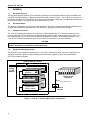
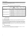
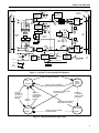
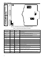
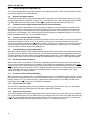
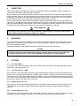
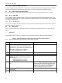
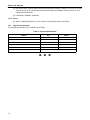
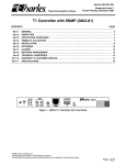
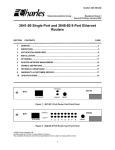
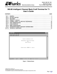
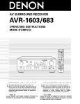
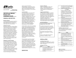
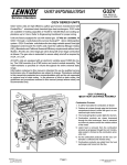
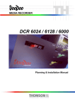
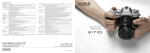
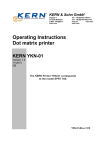
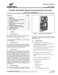
Section 319–29E–202
Charles Industries, Ltd.
Equipment Issue 2
Third Printing, June 1999
STS 3192–9E Powering T1 Network Interface Unit (NIU)
CLEI Code: T1STETT1AA
Recognized under Underwriters Laboratories Standard 1459, Second Edition*
CONTENTS
Part 1.
Part 2.
Part 3.
Part 4.
Part 5.
Part 6.
Part 7.
Part 8.
Part 9.
Part 10.
PAGE
GENERAL . . . . . . . . . . . . . . . . . . . . . . . . . . . . . . . . . . . . . . . . . . . . . . . . . . . . . . . . . . . . . . . . . . . . . . . . . . . . . 2
APPLICATION ENGINEERING . . . . . . . . . . . . . . . . . . . . . . . . . . . . . . . . . . . . . . . . . . . . . . . . . . . . . . . . . . . 3
CIRCUIT DESCRIPTION . . . . . . . . . . . . . . . . . . . . . . . . . . . . . . . . . . . . . . . . . . . . . . . . . . . . . . . . . . . . . . . . . 4
INSPECTION . . . . . . . . . . . . . . . . . . . . . . . . . . . . . . . . . . . . . . . . . . . . . . . . . . . . . . . . . . . . . . . . . . . . . . . . . . . 9
MOUNTING . . . . . . . . . . . . . . . . . . . . . . . . . . . . . . . . . . . . . . . . . . . . . . . . . . . . . . . . . . . . . . . . . . . . . . . . . . . . 9
OPTIONS . . . . . . . . . . . . . . . . . . . . . . . . . . . . . . . . . . . . . . . . . . . . . . . . . . . . . . . . . . . . . . . . . . . . . . . . . . . . . . 9
TESTING . . . . . . . . . . . . . . . . . . . . . . . . . . . . . . . . . . . . . . . . . . . . . . . . . . . . . . . . . . . . . . . . . . . . . . . . . . . . . 10
TECHNICAL ASSISTANCE . . . . . . . . . . . . . . . . . . . . . . . . . . . . . . . . . . . . . . . . . . . . . . . . . . . . . . . . . . . . . 12
WARRANTY & CUSTOMER SERVICE . . . . . . . . . . . . . . . . . . . . . . . . . . . . . . . . . . . . . . . . . . . . . . . . . . . 12
SPECIFICATIONS . . . . . . . . . . . . . . . . . . . . . . . . . . . . . . . . . . . . . . . . . . . . . . . . . . . . . . . . . . . . . . . . . . . . . 13
PWRG
T1
NIU
3192–9E
FA
NET
LOS
CI
LOS
LB
ESF
R
P
T
M
O
N
R
C
V
0.6V
R
P
T
M
O
N
X
M
T
MLB
WESCOM
91–31929E
ISS. 2
Figure 1. 3192–9E Powering T1 NIU
1999 Charles Industries Ltd.
CLEI is a trademark of Bell Communications Research, Inc.
All rights reserved. Printed in United States of America.
The availability of features and technical specifications herein subject to change without notice.
Page 1 of 14
Section 319–29E–202
1.
GENERAL
1.1
Document Purpose
This document provides general, circuit, and testing information for the Charles Industries Span Termination System (STS) 3192–9E Powering T1 Network Interface Unit (NIU), shown in Figure 1. The 3192–9E is a member of
the Charles Industries STS–3192 family of high density span termination equipment. For additional information on
the STS–3192 System, see sections 319–211–100 and 319–211–200.
1.2
Document Status
This practice is reprinted to correct Figure 4 and related text. The Issue 2 equipment provides one additional loop
up code and one additional loop down code over the Issue 1 equipment; form remains unchanged.
1.3
Equipment Function
The 3192–9E combines the functions of a Powering T1 Office Repeater plus a T1 Network Interface Unit conforming to Bellcore TR–TSY–000312 in a single high density plug-in module. When equipped in the 3192–11 23
inch mounting shelf, up to 28 3192–9E units can be provided in 5.25 inches of vertical equipment space. The
3192–9E can be intermixed with other plug in units of the STS-3192 Family in the shelf assembly.
CAUTION
Field repairs/modifications may void compliance with Underwriters Laboratories Standard 1459 – 2nd
Edition. Compliance is restricted to inside plant wiring.
1.4
Equipment Mounting/Location
The 3192–9E is fully qualified for operation over a –40 to 65C temperature range, and can be deployed in outside plant electronics cabinets or indoor building Remote Terminals, typically in Span Termination System
(STS–3192) Mounting Shelves.
Building Remote Terminal
ÇÇÇÇÇÇÇÇÇÇÇÇÇÇÇÇÇÇ
Ç
Ç
Ç
Ç
ÇÇÇÇ
Fiber
Facility
To LEC
Network
Lightwave
Multiplexer
DSX-1 Crossconnect
Customer CPE
Equipment
21 dB loss max.
3192–11 STS
Equipment Shelf
e/w 28 ea. 3192–9E
Network
Interface
Figure 2. 3192–9E T1 Powering NIU Typical Configuration
2
Section 319-29E-202
2.
APPLICATION ENGINEERING
The 3192–9E is ideally suited for use in provisioning T1 High Capacity Digital Service (HCDS) from lightwave-fed
building Remote Terminals located at customer premise locations. See Figure 2 for a typical application. The
3192–9E, used as adjunct equipment to the Lightwave Multiplexer, provides transmission loopback for maintenance activities. In addition, the 3192–9E can be optioned to provide a 60mA constant current power source towards the network interface, which can be used to power the customers’ Channel Service Unit (CSU). This service arrangement is typical in MPOP (Minimum Point Of Presence) applications.
The 3192–9E is intended to be co-located with the lightwave transport equipment and serves to extend the normal DSX range of that equipment. The 3192–9E provides a fixed DSX pre-equalizer for 0 to 110 feet of cable. In
the transmit direction the unit provides variable pads for level coordination toward the CPE. The 3192–9E can
accommodate up to 21dB of cable loss between the customer’s CSU and the 3192–9E.
Figure 3 shows a typical 3192–9E application with associated transmission levels.
Customer
Wiring
Maximum
Loss 21.0dB
(See NOTE)
–1.5dB
–1.5 To
–22.5dB
0.0
DSX–1
LBO
Pre
Equalizer
–1.5dB
-1.5 To
-22.5dB
3192–9E Powering T1 NIU
Lightwave
Multiplexer
Customer
Network
Interface
LEC Equipment
Note:
0.0
T1 CSU
Note:
Signal Levels Referenced
To 3V Base-To-Peak
CPE Equipment
Range is limited to maximum cable loss of 21.0db. See table below for maximum cable length at
various cable gauges.
CABLE @ 130 F
AERIAL - PIC
MAXIMUM
LENGTH -KF
TOTAL DCR
@ MAXIMUM
REFERENCE
LOSS - dB/KF
REFERENCE
LOSS - OHMS/
KF
REFERENCE
MAXIMUM
LOSS
22 GA-CU
4.29 KF
78 OHMS
4.9 dB/KF
18.3 OHMS
21.0dB
24 GA-CU
3.44 KF
100 OHMS
6.1 dB/KF
29.2 OHMS
21.0dB
26 GA-CU
2.56 KF
119 OHMS
8.2 dB/KF
46.7 OHMS
21.0dB
Figure 3. 3192–9E T1 Powering NIU Typical Configuration
2.1
Customer Interface Powering Options
The 3192–9E provides three, switch-selectable, CI (Customer Interface) side power modes: line powering, sealing current, and looped simplex. See Part 6 for more information.
2.2
System Power Engineering
The 3192–9E generates all necessary voltages for its operation from a –48V (nominal) battery input source. The
3192–9E contains an internal high efficiency DC–DC converter to minimize input current, and consequently, maximize battery reserve time in the remote terminal assembly.
3
Section 319–29E–202
The 3192–9E input current is highly dependent on application. Those applications that require the 3192–9E to
power a customer’s CSU will require a greater input current.
Table 1 shows input current and heat release versus the equivalent series simplex resistance (at 60mA) present
on the CI side of the unit.
Table 1. 3192–9E Power Consumption and Heat Release
Typical Application
Option S1
Position
Equivalent
External
Simplex
Resistance
–42.5 Volt
Battery
I
W
48.0 Volt Bat- 56.0 Volt Battery
tery
I
W
I
W
Non-CPE Powering
S1 = LP
N/A
0.07
2.86
0.06
2.87
0.06
3.00
Sealing Current Only
S1 = SC
0 Ohms
0.08
3.35
0.07
3.53
0.07
3.77
S1 = PWR
200 Ohms
0.10
2.91
0.08
3.02
0.07
3.12
S1 = PWR
400 Ohms
0.11
3.04
0.10
3.12
0.08
3.18
S1 = PWR
600 Ohms
0.13
3.09
0.11
3.12
0.10
3.13
S1 = PWR
800 Ohms
0.14
3.18
0.13
3.13
0.11
3.14
S1 = PWR
1000 Ohms
0.16
3.22
0.14
3.18
0.13
3.15
S1 = PWR
1200 Ohms
0.18
3.32
0.16
3.22
0.14
3.22
S1 = PWR
1400 Ohms
0.20
3.45
0.18
3.23
0.16
3.28
S1 = PWR
1600 Ohms
0.22
3.55
0.20
3.38
0.18
3.39
Powering Co-located 24V CSU
Powering Co-located 68V CSU
Note:
W = Heat release in watts
I = Input current in amps
2.3
Maintenance Loopback
The 3192–9E provides a signal path Loopback feature, which can be used to differentiate circuit problems on either side of the network interface.
The 3192–9E will respond to Loopback control codes in either SF or ESF protocols. SF control codes are received as 5 or 6 bit inband repeating patterns, while ESF codes are via 16 bit messages in the ESF framing data
link. The operation of this feature is automatic, that is, when the unit is passing unframed or SF framed traffic it
will recognized the 5 or 6 bit inband SF Loop codes, when the unit is passing ESF traffic it will only recognize the
ESF data link Loopback control codes.
When the 3192–9E is in the maintenance loopback state, it will send an AIS (all ones) signal toward the Customer Interface.
3.
CIRCUIT DESCRIPTION
Refer to Figure 4, the 3192–9E Block Diagram, Figure 5, the 3192–9E State Table, and Figure 6, Front Panel
Features and Options Location, when reading the following circuit description.
4
Section 319-29E-202
LIGHTWAVE
MULTIPLEXER
NET LOS
NETWORK
SIGNAL
DETECTOR
DSX
NETWORK
INTERFACE
AIS
GENERATOR
STEADY = LOS
FLASH = AIS
A
7.5
LB
ESF
1
S4
-
LB
MON
RPT
LB
RCV
MON
2
5
FRA
MEGND
+
-48V
RCV
4K
-
100
LB
LB
SURGE
PROTEC
TION
POWER
SUPPLY
AIS
GENERATOR
K
9
DISABLE
FA
GND
CI
Side
S1
LB
10
8
+
SC
-
S2
DSX
PREEQ
XMT
LP
ASPR
0-96V
SIGNAL
REGEN
B
-BATT
+
LOOPDOWN
CONTROL
RPT
MLB
FA
PWR
CONTROL
LOGIC
XMT
Network
Side
F
6
XMT LBO
BUFFER
AMP
LOOPBACK
CODE
DETECTOR
SURGE
PROTEC
TION
7.5
CPE
EQUIPMENT
CSU
DISABLE
ENABLE
S3-2
AIS
CUSTOMER
INTERFACE
SIGNAL
DETECTOR
DISABLE
S3-1
LOS ALM
H
LOS
ALM
FLASH = SENDING AIS
STEADY = CI LOS
CI LOS
J
Figure 4. 3192–9E T1 Powering NIU Block Diagram
DETECT LOS FROM
CUSTOMER INTERFACE
IDLE
STATE 1
DETECT SIGNAL PRESENT
CUSTOMER INTERFACE
RECEIVE
LOOPUP SIGNAL FROM
NETWORK
OR MLB
20 MIN.
TIMEOUT
RECEIVE
LOOPDOWN
SIGNAL FROM
NETWORK
OR MLB
RECEIVE LOOPUP SIGNAL
FROM NETWORK
RECEIVE
LOOPDOWN
SIGNAL FROM
NETWORK
DETECT SIGNAL PRESENT
CUSTOMER INTERFACE
CI LOS
CUT-THRU
LOOPBACK
STATE 2
CI LOS
NOTIFICATION
STATE 3
RECEIVE LOOPUP SIGNAL
FROM NETWORK
STATE 4
Figure 5. 3192–9E Operational State Table
5
Section 319–29E–202
PWRG
T1
NIU
O
N
3192-9E
FA
NET
LOS
CI
LOS
LB
7.5
1
7.5
2
S4
ESF
R
P
T
M
O
N
R
C
V
LOS
ALM
A
I
S
1
2
DISABLE
S3
0.6V
PWR
LP
SC
S1
R
P
T
M
O
N
X
M
T
MLB
S2
WESCOM
91-31929E
ISS. 2
Figure 6. 3192–9E Front Panel Features and Options Location
Table 2. 3192–9E Front Panel Options Description
Feature/Option
Location
Description
Function
FA (Fuse Alarm)
Front Panel
Red LED
Indicates that the internal fuse on the 3192-9E has opened. The internal fuse is
not field replaceable.
NET LOS (Loss of
Signal)
Front Panel
Red LED
Continuous: Indicates LOS (Loss Of Signal) from the network side.
Flash: Indicates receipt of AIS from the network side.
CI LOS (Loss of
Signal)
Front Panel
Red LED
Continuous: Indicates loss of signal from the customer interface side.
Flash: Indicates sending of AIS to the network side.
LB (Loopback)
Front Panel
Amber LED
Indicates that the unit is in the Loopback State.
ESF (Extended
Superframe)
Front Panel
Green LED
Indicates ESF Framed signal from the network.
RCV RPT
Front Panel
Bantam Jack
Isolates the DSX allowing access to repeater RCV DSX (OUT).
RCV MON
Front Panel
Bantam Jack
RCV DSX (OUT) monitor jack.
+ Test Pins
Front Panel
Pin Jack
Used for measuring span current and voltage.
– Test Pins
Front Panel
Pin Jack
Used for measuring span current and voltage.
XMT RPT
Front Panel
Bantam Jack
Isolates the DSX, allowing access to repeater XMT DSX (IN).
XMT MON
Front Panel
Bantam Jack
XMT DSX (IN) monitor jack.
S1
PC Board
3 Position Slide
Switch
3position switch to select either PWR (line powering), SC (Sealing Current) or
LP (Looped Simplex) CI side power modes.
S2
Front Panel
Front Panel Pushbutton Switch
S2 is the recessed front panel MLB (Manual Loopback) pushbutton switch to
manually activate or deactivate loopback.
S3
PC Board
2 Section Dip
Switch
S3–1 enables or disables a LOS condition alarm detected by CI side.
S3–2 enables or disables the operation of the Customer Receive Side AIS generator.
S4
PC Board
2 Section Switch
Adjusts the transmit pad, allowing a transmit path loss of 0, 7.5 or 15 dB.
6
Section 319-29E-202
3.1
Signal Transmission Paths
In the idle (Looped down) mode, the signal from the network is coupled to the unit and routed through the transmit pad circuit. Switch S4 mounted on the circuit pack is used to adjust the transmit pad which consists of two
cascaded 7.5dB sections, allowing transmit path losses of 0, 7.5 and 15dB.
The signal from the customer is routed through the receive side of the 3192–9E. This side contains a signal regenerator with a wide range ALBO, accommodating signal levels from 0 to –35dB. After regeneration, the signal
is passed through a fixed DSX–1 pre-equalizer which will accommodate up to 110 feet of 22ga or 90 feet of 24ga
cable to the DSX–1 point.
3.2
Signal Loopback Operation
The signal from the network is continually monitored by the Loopback Code Detector for Loopback control sequences from the network. The detector will automatically configure itself to recognize either inband (SF) or data
link (ESF) control sequences. When the detector detects ESF framed traffic, it will only recognize Loopback control sequences in the ESF data link. In addition, when ESF traffic is present, the unit’s front panel ESF indicator
(green) will light.
3.3
Loopback Activation (State 1 State 2)
To activate loopback utilizing the SF protocol, a repetitive pulse pattern of two ones followed by three zeros
(11000) or one one followed by five zeros (100000) is applied to the line. The Code Detector will reject the pulse
pattern if it is less than 5 seconds in duration or if its error rate is greater than 10-. The circuitry will accept a
pulse pattern if it is greater than 5 seconds in duration.
To activate loopback utilizing the ESF protocol, the Code Detector monitors the 4kHz Data Link Channel of the T1
bit stream for the following repetitive pulse pattern; 0 001001 0 11111111 where the rightmost bit is transmitted
first. The pattern is acknowledged as valid when it has been received by the Code Detector four consecutive
times. This corresponds to 16ms.
The unit can manually be placed in the loopback state by momentarily operating the recessed front panel MLB
pushbutton switch.
After the code pattern is detected for the proper duration or a MLB pushbutton operation is detected, the Loopback Controller will operate the LB Relay.
3.3.1.
Loopback Mode (State 2)
When the unit is in the loopback state, the CPE equipment is disconnected from the network and terminated in
100 ohms. The signal from the network is looped back toward the network. The front panel LB LED (amber) is on
and an AIS (all ones) signal is sent toward the Customer Interface.
3.3.2.
Loopback Timeout/Retrigger
The 3192–9E provides a fixed 20 minute loopback timeout. Normally after 20 minutes the loopback state will
timeout and release. When the 3192–9E is in loopback, a reapplication of any of the loopback activation sequences will reset the timer for a new 20 minute period.
3.4
Loopback Deactivation (State 2 State1)
To deactivate loopback utilizing the SF protocol, a repetitive pulse pattern of 3 ones followed by 2 zeroes (11100)
or 1 one followed by 2 zeroes (100) is applied to the line. The Loopback Code Detector will reject the pulse pattern if it is less than 5 seconds in duration or if its error rate is greater than 10-. The Loopback Code Detector will
accept a pulse pattern if it is greater than 5 seconds in duration.
To deactivate loopback utilizing the ESF protocol, the Code Detector monitors the 4kHz Data Link Channel of the
T1 bit stream for the following repetitive pulse pattern; 0 010010 0 11111111 where the rightmost bit is transmitted first. The pattern is acknowledged as valid when it has been received by the Code Detector four consecutive times. This corresponds to 16ms.
To deactivate loopback manually, the front panel MLB push button switch is momentarily operated.
When loopback is deactivated, the Loopback Controller releases the LB relay, restoring the thru transmission path
from network to CPE, extinguishing the LB LED, and removing the AIS signal that was being sent toward the
Customer Interface.
7
Section 319–29E–202
3.5
Transmit And Receive Signal Detectors
The 3192–9E provides Monitoring Signal Detectors on the transmission paths. These detectors provide a maintenance aid for installation and troubleshooting.
3.6
Network Side Signal Detector
This detector monitors the unit’s transmit path and looks for signal activity from the network. When a LOS (Loss
Of Signal) is detected, as indicated by receipt of 175 +75 consecutive zeros, it will illuminate the front panel NET
LOS LED. When an AIS (all ones) signal is detected, the unit will flash the front panel NET LOS LED.
3.7
Customer Interface Signal Detector And Receive Side AIS Generator
The Customer Interface Signal detector and receive side AIS generator are used together and provide several
important maintenance features that can sectionalize problems across the customer interface. Operation of this
AIS generator feature is controlled by switch S3–2 (another AIS generator, not controlled by S3–2, sends AIS
toward the CI upon loopback). The Customer Receive Side AIS generator is enabled by placing S3–2 in the AIS
position and disabled when S3–2 is in the DISABLE position.
3.8
Customer Interface LOS (AIS Enabled)
The Customer Interface Signal detector continuously monitors the unit’s receive path. If a LOS (Loss Of Signal) is
detected, as indicated by receipt of 175 +75 consecutive zeros from the customer’s equipment, a LOS is declared. This is shown as the transition from State 1 to State 3 (see Figure 5). In State 3, the unit will now send an
AIS signal toward the network as an indication that the customer equipment is disconnected or not operational.
The CI LOS LED will flash since the unit is sending AIS.
3.9
Loss Of Customer Interface Signal Alarm
When the Customer Interface (CI) Side Signal detector has declared a LOS condition, it will also forward a signal
to the shelf LOS bus, which is summarized by the 3192–9F module mounted in the far right hand position of the
STS shelf assembly. This alarm output can be disabled by placing switch S3–1 in the DISABLE position. To allow
the LOS alarm from the 3192–9E to be forwarded to the shelf alarm buss, place S3–1 in the LOS ALM position.
3.10
AIS Override (State 3 State 4)
With the unit in State 3 it is possible to override the AIS signal generator and cause the unit’s receive path to be
cut-thru from the customer equipment to the network. This override is accomplished by sending the unit a Loopdown signal in the SF, or ESF formats as previously described. When the loopdown signal is received, the unit
will stop sending AIS and enter State 4. If the CI signal subsequently returns, the unit will transition back to State
1 (idle). Alternately, the unit can be placed in the loopback state by receipt of a valid loopback code. This is
shown as the State 4 to State 2 transition.
3.11
Customer Interface LOS (AIS Disabled)
When the AIS feature is disabled (S3–2 in the DISABLE position), the CI LOS detector monitors the unit’s receive
path and looks for signal activity from the customer equipment. When a LOS (Loss Of Signal) is detected, as indicated by receipt of 175 +75 consecutive zeros, it will illuminate the front panel CI LOS LED (LOS LED will not
flash). When the CI signal returns, the CI LOS LED will extinguish.
3.12
Signal Test Access Jacks
The 3192–9E provides both splitting and monitor bantam jack access on the DSX side of the unit. The splitting
jacks provide access looking toward the 3192–9E and are labeled RPT (repeater).
3.13
Span Current Test Points
The 3192–9E provides front panel test points that can be used to measure the CI side simplex current. When the
unit is in the POWER mode (S1 in the PWR position), the reading across both the RCV and XMT sides should be
0.6 +0.03V indicating 60mA of span current. If only sealing current is supplied on the CI loop (S1 in the SC position), the voltage reading should be approximately 0.12 volts (i.e. 12mA across 10 ohms).
8
Section 319-29E-202
4.
INSPECTION
Inspect the equipment thoroughly upon delivery. If the equipment has been damaged in transit, immediately report the extent of damage to the transportation company.
Wescom equipment is identified by a model and issue number imprinted on the front panel or located elsewhere
on the equipment. Each time a major engineering design change is made on the equipment, the issue number is
advanced by one number on any subsequent models that are manufactured. Therefore, be sure to include both
the model number and its issue number when making inquiries about the equipment.
Each module is shipped in static-protective packaging to prevent electrostatic charges from damaging static-sensitive devices. Use approved static-preventive measures, such as static-conductive wrist straps and a static-dissipative mat, when handling modules outside of their protective packaging. A module intended for future use should
be tested as soon as possible and returned to its original protective packaging for storage.
STATICSENSITIVE
Do not ship or store modules near strong electrostatic, electromagnetic, or magnetic fields. Use the
original static-protective packaging for shipping or storage.
5.
MOUNTING
The 3192–9E is fully qualified for operation in a –40 to 65C temperature range, and can be deployed in outside
plant electronics cabinets or indoor building Remote Terminals, typically in Wescom Span Termination System
(STS–3192) Mounting Shelves.
Complete the optioning in Part 6 before installing the 3192–9E unit into a shelf or assembly.
CAUTION
Installation and removal of modules should be done with care. Do not force a module into place. If
excessive resistance is encountered while installing a module, remove the module and check the
card guides and connector to verify proper alignment and the absence of foreign material.
6.
OPTIONS
6.1
SI—Power Mode
S1 (see Figure 6) is a 3-position slide switch used to select CI side power modes: line powering (PWR), sealing
current (SC), and looped simplex (LP).
6.1.1.
Line Powering, S1 = PWR
In this mode the 3192–9E provides an Automatic Span Power Regulator (ASPR) circuit that automatically generates up to 96V of regulated span voltage at a constant 60mA of current. This power source can be used to power
the customer’s CSU and/or intermediate span line repeaters as long as the total voltage drop does not exceed 96
volts or 1600 ohms of equivalent simplex resistance at 60mA. Note that the customer’s terminal equipment (CSU)
plus wiring can require up to 68V per FCC P.68 rules.
6.1.2.
Sealing Current, S1 = SC
In this mode the 3192–9E provides approximately 12mA of sealing current toward the customer equipment. The
CPE equipment must be locally powered and should be optioned to provide a looped simplex path toward the
3192–9E.
6.1.3.
Looped Simplex, S1 = LP
In this mode the 3192–9E loops the CI side simplex leads. This mode can be used if the CPE equipment provides
a sealing current source toward the network, or if no sealing current is provided across the interface.
9
Section 319–29E–202
6.2
S2 — Front Panel MLB Push Button
S2 is a recessed, front-panel push-button switch used to manually activate or deactivate loopback. Momentarily
depress the MLB (Manual Loopback) push-button switch to activate or deactivate a loopback condition.
6.3
S3 — LOS ALM and AIS Enable/Disable
S3 is a two-section dip switch that interacts with the transmit and receive signal detectors on the 3192–9E.
6.3.1.
S3–1 — LOS ALM
S3–1 is used to enable or disable sending a LOS (Loss of Signal) condition alarm to the shelf alarm buss. The
LOS condition is detected by the Customer Interface Side Signal detector. For more information, see Paragraphs
3.10 and 3.11, and Figure 6.
6.3.2.
S3–2 — AIS Generator
S3–2 is used to enable or disable operation of the Customer Receive Side AIS generator that sends AIS toward
the network upon LOS from the CI.
6.4
S4 — XMT Pad dB
S4 is a 2-section switch used to adjust the transmit pad, allowing transmit path losses of 0, 7.5 and 15dB. See
Figure 6.
7.
TESTING
The procedure shown in Table 3 can be used to verify operation of the 3192–9E for pre-service checkout.
Table 3. 3192–9E Verification of Operation and Performance Test Procedure
Note:
Step
Requires TBERD209 Digital Transmission Test Set or Equivalent.
Action
Action
1.
Option the 3192–9E as follows:
Set Switch S3–2 (AIS) to the DISABLE position.
Set Switch S3–1 (LOS ALM) to the DISABLE position.
Set Switch S1 (PWR) to the LP position.
Set Switch S4 (XMT LBO) for 7.5dB.
2.
Insert the 3192–9E into the shelf assembly.
3.
Disconnect the CPE at the Network Interface.
4.
Connect the Digital Transmission Test Set
(TBERD-209) to the 3192–9E via its front panel
jacks as follows:
TBERD-209 SEND to XMT RPT.
TBERD-209 RCV to RCV RPT.
5.
Set the TBERD-209 to transmit an all Zeros pattern.
All the 3192–9E front panel LEDs should be off
except for the NET LOS and CI LOS LEDs which
should be on. This indicates NO signal from the
network or CPE equipment. The TBERD-209
should be receiving a NO signal condition.
6.
Condition the TBERD-209 to send an AIS (all
ones) signal.
The 3192–9E NET LOS LED should flash.
7.
Change the TBERD-209 to send a QRSS pattern.
The 3192–9E NET LOS LED should extinguish.
10
Section 319-29E-202
Step
Action
Action
8.
Momentarily operate the 3192–9E front panel MLB The 3192–9E front panel LB LED should light indipushbutton switch.
cating that the unit is in Loopback and the
TBERD-209 should be receiving the looped back
QRSS pattern.
9.
Momentarily operate the 3192–9E front panel MLB The 3192–9E front panel LB LED should extinpush-button switch.
guish and the TBERD-209 shows no signal.
10.
Connect the TBERD-209 RCV to the Network Interface OUT or ‘Transmit’ (this point will vary by
installation. The intent is to access pins F and 6 of
the 3192–9E card-edge-connector).
The TBERD-209 should see the QRSS pattern
attenuated by 7.5dB.
11.
Condition the TBERD-209 to send the inband
loop-up code (11000 or 100000) for greater than 5
seconds, and then return to QRSS.
The 3192–9E front panel LB LED should light and
the TBERD-209 should receive an AIS (all ones)
signal from the 3192–9E.
12.
Condition the TBERD-209 to send the inband
loop-down code (11100 or 100) for more than 5
seconds, then return to QRSS.
The 3192–9E front panel LB LED should extinguish & the TBERD-209 shows the QRSS signal
down 7.5dB.
13.
Connect the TBERD-209 SEND to the Network
Interface IN or ‘Receive’ (this point will vary by
installation. The intent is to access pins K and 9 of
the 3192–9E card-edge-connector).
Reconnect the TBERD-209 RCV to the 3192–9E
front panel jack RCV RPT. Verify that the test set
is still sending QRSS.
The 3192–9E front panel CI LOS LED should be
extinguished and the TBERD-209 should be receiving the QRSS signal.
14.
Disconnect all test set connections. Back out the
3192–9E, set S1 (PWR) to the PWR position. Set
S3–2 to the AIS position and reinsert the unit.
The 3192–9E front panel CI LOS LED should flash
indicating that the unit has detected a customer
Loss-Of-Signal (LOS) and is sending AIS. The
TBERD-209 should be receiving AIS (all ones).
CAUTION: The customer interface will now have
up to 96V on the pairs.
Connect the TBERD-209 SEND to the 3192–9E
front panel XMT RPT jack. Connect the
TBERD–209 RCV to the 3192–9E front panel RCV
RPT jack.
15.
Condition the TBERD-209 to send the loop-down
code (11100 or 100).
The 3192–9E front panel CI LOS LED should
change from flashing to steady and the
TBERD-209 should read NO signal.
16.
Condition the TBERD-209 to send NO signal (all
zeros).
Using a Voltmeter, measure the voltage across the
front panel XMT + and – pin jacks. The voltage
should be approximately 0.6V indicating proper
operation of the ASPR circuit (delivering 60mA to
the load). Repeat this test across the RCV + and –
pins jacks and verify approximately 0.6V.
CAUTION: The customer interface will now have
up to 96V on the pairs.
At the Customer Network Interface, connect the
receive pair to the transmit pair which will close the
simplex loop.
17.
This completes the basic test of the 3192–9E. Disconnect all test equipment and test leads. Disconnect the loop setup which connected the receive
pair to the transmit pair. Set all switch options to
their design/application settings and perform any
additional end to end circuit checks per local procedure.
11
Section 319–29E–202
8.
TECHNICAL ASSISTANCE
8.1
Technical Assistance — U.S.
If technical assistance is required, contact Charles Industries’ Technical Services Center at:
847–806–8500
847–806–8556 (FAX)
800–607–8500
[email protected] (e-mail)
8.2
Technical Assistance — Canada
Canadian customers contact:
905–821–7673 (Main Office)
905–821–3280 (FAX)
9.
WARRANTY & CUSTOMER SERVICE
9.1
Warranty
Charles Industries, Ltd. offers an industry-leading, 5-year warranty on products manufactured by Charles Industries. Contact your local Sales Representative at the address or telephone numbers below for warranty details.
The warranty provisions are subject to change without notice. The terms and conditions applicable to any specific
sale of product shall be defined in the resulting sales contract.
Charles Industries, Ltd.
5600 Apollo Drive
Rolling Meadows, Illinois 60008–4049
Telephone:
9.2
847–806–6300 (Main Office)
847–806–6231 (FAX)
Field Repairs (In-Warranty Units)
Field repairs involving the replacement of components within a unit are not recommended and may void the warranty and compatibility with any applicable regulatory or agency requirements. If a unit needs repair, contact
Charles Industries, Ltd. for replacement or repair instructions, or follow the Repair Service Procedure below.
9.3
Advanced Replacement Service (In-Warranty Units)
Charles Industries, Ltd. offers an “advanced replacement” service if a replacement unit is required as soon as
possible. With this service, the unit will be shipped in the fastest manner consistent with the urgency of the situation. In most cases, there are no charges for in-warranty repairs, except for the transportation charges of the unit
and for a testing and handling charge for units returned with no trouble found. Upon receipt of the advanced replacement unit, return the out-of-service unit in the carton in which the replacement was shipped, using the preaddressed shipping label provided. Call your customer service representative at the telephone number above for
more details.
9.4
Standard Repair and Replacement Service (Both In-Warranty and Out-Of-Warranty Units)
Charles Industries, Ltd. offers a standard repair or exchange service for units either in- or out-of-warranty. With
this service, units may be shipped to Charles Industries for either repair and quality testing or exchanged for a
replacement unit, as determined by Charles Industries. Follow the Repair Service Procedure below to return units
and to secure a repair or replacement. A handling charge applies for equipment returned with no trouble found. To
obtain more details of this service and a schedule of prices, contact the CI Service Center at 217–932–5288 (FAX
217–932–2943).
Repair Service Procedure
1. Prepare, complete, and enclose a purchase order in the box with the equipment to be returned.
12
Section 319-29E-202
2. Include the following information:
– Company name and address
– Contact name and phone number
– Inventory of equipment being shipped
– Particulars as to the nature of the failure
– Return shipping address
3. Ship the equipment, purchase order, and above-listed information, transportation prepaid, to the service center address shown below.
CI Service Center
Route 40 East
Casey, IL 62420–2054
4. Most repaired or replaced units will be returned within 30 or 45 days, depending on the product type
and availability of repair parts. Repaired units are warranted for either 90 days from the date of repair
or for the remaining unexpired portion of the original warranty, whichever is longer.
10.
SPECIFICATIONS
10.1
Electrical Specifications
The electrical characteristics of the 3192-9E are as follows:
(a) REPEATER TYPE: Passive transmit;
regenerative receive.
(b) LINE SIGNAL TYPE: Bipolar at 1.544Mbps +200bps.
(c) TRANSMIT PATH PAD: Selectable 0.0dB, 7.5dB, or 15.0dB.
(d) DSX PRE-EQUALIZER: Fixed 0–110 feet, 22ga; 0–90 feet, 24ga.
(e) REPEATER LINE SIGNAL PULSE WIDTH: 324nsec +30nsec.
(f) REPEATER LINE SIGNAL PULSE WIDTH UNBALANCE: 15nsec maximum.
(g) REPEATER LINE SIGNAL PULSE OVERSHOOT: 10 to 30 percent of pulse height, 20 percent nominal.
(h) REPEATER LINE SIGNAL PULSE RISE AND FALL TIME: 100 nsec maximum.
(i) INPUT/OUTPUT IMPEDANCE: 100 ohms (nominal) at 772kHz.
(j) RECEIVE AUTOMATIC LINE BUILD-OUT: 0 to 35dB.
(k) TIMING JITTER: Meets the Jitter Transfer Specifications as described in TR-TSY-000312 .
(l) LONGITUDINAL BALANCE: Greater than 35dB from 50kHz to 1.5 mHz.
(m) INSERTION LOSS: Transmit path 1.5dB nominal.
(n) LOSS-OF-SIGNAL THRESHOLD: 175 +75 consecutive zeros.
10.1.1. Loopback
(a) LOOPBACK ERROR THRESHOLD: 10– error rate or better.
(b) LOOPBACK CODE:
SF: Framed or unframed 2 in 5 (11000) or 1 in 6 (100000) to loop up (approximately 5 seconds); 3 in
5 (11100) or 1 in 3 (100) to loop down (approximately 5 seconds).
13
Section 319–29E–202
(c) ESF DATA LINK: The bit-oriented command and response message 0 001001 0 11111111 for 16 milliseconds to loop up. The bit-oriented command and response message 0 010010 0 11111111 for 16
milliseconds to loop down.
(d) LOOPBACK TIMEOUT: 20 Minutes
10.1.2. Power
(a) INPUT: Voltage Requirements, –42.5 to 56Vdc; Current Requirements, see Table 1.
10.2
Physical Specifications
The physical specifications of the 3192-9E are as follows:
Table 4. Physical Specifications
Feature
U.S.
Metric
Height
4.75 inches
12.06 cm
Width
0.687 inches
1.746 cm
Depth
10.5 inches
26.67 cm
Weight
12 oz.
198 g
Temperature
–40 to 149
Humidity
To 95% (no condensation)
F
14
–40 to 65 C