1
(j
I Sears I
owners
manual
Provided By:
WheelHorse.org
"
o
..
MODEL NO.
917.251880
CAUTION:
Read Rules for
Safe Operation
and Instructions
Carefully
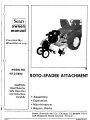
ROTO-SPADER ATTACHMENT
• Assembly
• Operation
• Maintenance
• Repair Parts
Sears, Roebuck and Co., Chicago, Ill. 60684 U.S.A..
and Simpsons Sears Limited, Toronto
···"nOLO
PRINTED IN U.S.A.
o
During the first 90 days, we will repair your Roto-Spader Attachment, free of charge, if defective
in material or workmanship.
In addition, during the first year, we will replace any broken tines, free of charge.
This guarantee service is available by simply contacting any of our stores or service centers
throughout the United States or Canada.
If the Roto-Spader Attachmant is used for commercial or rental purposes, this guarantee is limited
to 30 days.
SEARS, ROEBUCK AND CO., CHICAGO, ILL. 60684 U.S.A.
and SIMPSONS-SEARS LIMITED, TORONTO
7086R -11.10.74
G
SAFETY PAYS OFF
o
IMPORTANT
read rules for safe operation
o
1.
Know the controls, and how to stop quickly. Read the
Owner's Manual thoroughly.
13.
Lift Spader attachment out of the ground when turning
corners.
2.
Do not allow children to operate your tractor and RotoSpader attachment. Do not allow adults to operate them
without proper instruction.
14.
Do not put tractor in reverse gear while Spader is in the·
ground.
3.
Keep children and pets a safe distance away.
15.
4.
Clear work area of objects which might be caught in tines.
5.
Before starting the engine, be sure clutch is disengaged,
and tines are clear.
6.
Make sure of your footing and stand clear of tines when
starting engine.
7.
Do not run engine indoors, because the engine-exhaust
fumes contain carbon monoxide, which is a tasteless,
odorless, deadly poison.
Keep all nuts, bolts and screws tight in order to. be sure
that the tractor and attachment are in safe working condition. Be sure the brake and all powered attachment
controls are always in proper adjustment and repair.
Check the attachment and engine mounting bolts at frequent intervals for proper tightness. Before performing
any maintenance, always disengage the power to attachment, set the parking brake, shift into neutral, shut off
the engine, make absolutely sure the Spader attachment
and all moving parts have completely stopped, remove
ignition key, disconnect the spark-plug wire from the
spark plug and keep it away from the plug to prevent injury or accidental starting. The only exception to this
rule is carburetor adjustment.
8.
Check fuel supply before each use. Never remove the gas
cap or fill the gasoline tank when engine is running or
while it is hot. When filling the fuel tank, leave space for
expansion; do not fill it to the brim and keep in mind
that the heat of the sun can cause the gasoline to expand.
Wipe off any spilled gasoline before starting the engine.
Remember, gasoline is highly flammable and must always
be handled with extreme care.
16.
9.
Stop tractor, disengage Roto-Spader attachment clutch
and stop Spader and tractor, engines. Shift tractor to neutral position, set parking brake, and remove ignition key
before leaving operator's position.
Keep the engine free from accumulations of grass, leaves .
or excessive grease, as these accumulations are combustible and could result in a fire. Always keep your RotoSpader attachment in good operating condition and make
sure that all shields, guard plates and all other protective
devices are in place. Give your Spader attachment the
regular maintenance it needs and have a competent service technician make a thorough inspection of it at least
once a year.
17.
Do not store your Roto-Spader attachment for prolonged
periods (more than 30 days) with gasoline in the tank.
Do not store your Spader attachment or a gasoline container inside a building where fumes may reach an open
flame or spark; they should be stored in a cool, dry
place. Be sure to let the engine cool before storing in any
enclosure. Always use an approved gasoline container for
storing gasoline and keep your Spader attachment and
gasoline container in locked storage to prevent children
from playing and tampering with them.
10.
Never stand near tines or work on tines when engine is
running.
11.
Watch for traffic when crossing or near roadways.
.0n12.
Always disengage Roto-Spader clutch, and stop engine
when travelling to and from field or when not tilling.
7086R - 11.10.74
r-·
I
TABLE OF CONTENTS
GUARANTEE
'"
5. Fill engine crankcase to overflowing with S.A.E. 30 oil, API
rating MS, SC. SO or SE. Because of recent changes in the
classifications. the oil container may show one or a ·combination of these recommended classifications. Capacity: About
2% pints. Refer to Figure 7 for location of engine fill plug.
Inside Front Cover
RULES FOR SAFE OPERATIOI\!
1
READ YOUR OWI\!ER'S MANUAL CAREFULLY.
ASSEMBLY INSTRUCTIONS
2-4
OPERATION INSTRUCTIONS
5-6
MAII\!TENANCE INSTRUCTIONS
6·9
REPAIR PARTS .................•...... 10-19
o
TOOLS AND ITEMS
NEEDED
INTRODUCTION
The following is a list of all the tools and supplies needed to
assemble and initially service your Spader Attachment.
This Roto-Spader has been designed, engineered and manufactured to give you the best possible dependability and performance.
1 Wrench (open or box end) 9/16
Should you experience any problem you cannot easily remedy,
please contact your neare~t Sears, Roebuck and Co. or Simpsons-Sears, Ltd. store. They have well-qualified, competent,
trained technicians and the proper tools to service or repair
your Spader. It is important that the operator ALWAYS
OBSERVE THE "RULES FOR SAFE OPERATION"
Q
as well as other instructions contained in this Manual. We have
provided this Manual to help operate your Spader with utmost
efficiency. We urge you to study this Manual so you will understand your new Spader thoroughly before operating it. We suggest that you take care of your Manual so that it will be available for future reference.
ASSEMBLY INSTRUCTIONS
A letter in parentheses in the following instructions refers to an
arrow in the adjoining Figure (illustration), except when otherwise stated. When "R.H." (Hight Hand) or "L.H." (Left Hand)
is used. it should be understood to mean as if one were seated
on the tractor seat facing forward.
DO THIS FIRST
Your Spader has been shipped from the factory partially
assembled for shipping purposes. Open the bags of parts at
this time. The contents of the bags of parts are as follows:
1. Cut all four corners of shipping carton down from top to
bottom.
1
Owner's Manual
1 - Lift link and stop-L.H. (D. Figure 1A)
1
Lift link and chain-R.H. IZ, Figure 1A)
5
Retainer springs (1 on each end of 0, and one at L,
Figure 1A)
1
Clevis (J, Figure 1A)
1
. Rivet (K, Figure 1A)
1
Lift handle extension (V, Figure 1B)
1
U-Bolt plate (X, Figure 1B)
2
U-Bolts (X, Figure 1B)
4 - Locknuts (Y, Figure 1B)
. 2. Cut all wires which fasten Spader to wood pallet on bottom
of carton.
3. Remove Spader. bag of hardware and all parts from carton.
4. IMPORTANT: Check oil level in transmission and fill to
level of oil filler plug, if necessary. Use S.A.E. 30 motor oil
MS, SC, SO or SE. To fill the transmission. use a smallflexible neck funnel. Refer to Figure 7 for location of
filler plug.
7086R-20.1.75
2
(])
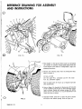
REFERENCE DRAWING FOR ASSEMBLY
AND INSTRUCTIONS
o
FIG. 18
FIG. 1A
1. Place Spader on level ground where tractor can be backed
up to Spader for assembly. Adjust Spader gauge wheels (A)
so that engine is level. Refer to "Tilling Depth," page 5, for
adjusting instructions.
2. Remove the following items from the three-point hitch.
Refer to Figure 2.
Lift link--L.H. (8)
Lift link upper--R.H., turnbuckle and lift link lower
R.H. (e), assembled together.
Save the above parts for future use of 3-point hitch with
other attachments.
3. Refer to Figure 1A. Assemble the floating-type l,ift links (D)
& (Z) (included in bag of parts to inner holes (E) of each
lever, as shown. Secure with retainer springs (U). NOTE:
Offset end of links must be to top and positioned in the
lower two holes, as shown.
o
4. Assemble lift-link swivel IF) to lower lift arms as shown
and secure with retainer springs. Refer to Figure 1A.
FIG.2
7086R-20.1.75
3
5. With lift lever in forward (raised) position, attach limit
chain (G) to lift-lever cross-shaft (H) with clevis (J). Secure
with rivet (K) and retainer spring (L). Refer to Figure 1A
1. Check oil level in transmission and engine. Transmission
capacity: 1% quarts; oil should be to level of fiUer hole.
Engine capacity: Approximately 2% pints. Fill to overflowing. NOTE: Spader must be level. Fill fuel tank with clean,
fresh, regular-grade gasoline. Capacity: 1 gallon. Wipe off
any spilled fuel and oil.
6. Back tractor up to Spader and attach rear of bottom links
(M) to pin (N) Or) Spader and secure with retainer spring (P).
Refer to Figure 1A.
1\'1
¥
NOTE: There are two (2) grease fittings on your Spader. One
at each outboard bearing. Use Multipurpose Pressure Gun
Grease. Fill until grease comes out the inner end of bearings.
Grease every eight (8) hours. Figure 7, page 5.
7. Assemble clevis (Q) to hitch bar (R).
NOTE: It may be necessary to adjust adjusting screw and
handle (S) to assemble clevis (Q) to hitch bar (R l. and to
2. Lift Spader with 3-point hitch. Be sure Spader clutch lever is
disengaged (lever pulled down). Refer to Figure 14.
keep Spader level. Secure with retainer spring (T).
8. Assemble lift handle extension (V) to lift lever (W) with Ubolts, plate and locknuts (X). Tighten nut securely.
Refer to Figure 1B.
3. Open fuel shut-off valve. Shut off this valve after each day's
operation. Refer to Figure 3.
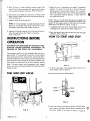
HOW TO START AND STOP
INSTRUCTIONS BEFORE
OPERATION
WARNING TO PURCHASERS OF INTERNAL-COMBUSTION ENGINE-EQUIPPED MACHINERY OR
DEVICES IN THE STATE OF CALIFORNIA
The equipment which you have purchased does not have a
spark arrester. If this equipment is used on any forest-covered
land, brush·covered land or grass-covered, unimproved land in
the state of California, before using on such land, the California
law requires that a spark arrester be provided. In addition, such
spark arrester is required by law to be in effective working
order. The spark arrester must be attached to the exhaust
system and comply with Section 4442 of the California Public
Resources Code.
FIG.4
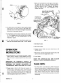
1. To start a cold engine, move manual choke control to full
choke position; refer to Figure 4.
FUEL SHUT-OFF VALVE
2. Place throttle control in RUN position.
FAST
SLOW
RUN
STOP
STOP
FIG.5
3. Grasp recoil starter handle and pull sharply. DO NOT allow
starter rope to snap back. Rewind slowly, keeping hold of
FIG.3
7086R-20.1.75
the starter handle at all times, as shown in Figure 6.
4
~)
3. Check oil in transmission at the time of the initial engine
oil change and prior to each use. Remove pipe plug
located on R.H. side of transmission. Oil level must be
even with bottom of plug. If necessary, add Allstate
S.A.E. 30 motor 'oil for service, MS,SC,SD or SE.
Replace pipe plug.
o
ENGINE 01 L
FILL PLUG
ENGINE 01 L
DRAIN PLUG
FIG.6
4. As engine warms up and begins to operate evenly, advance
choke control to 'h position and then to NO CHOKE. If engine falters, return to 'h choke until engine runs smoothly,
then advance to NO CHOKE position.
5. Engage Spader clutch lever (lever pulled up); refer to Figure
14. Then disengage several times to check the clutching action of the belts. If it is not clutching properly, see "Belt
Adjustment," page 8.
o
6. To stop Spader and engine, release Spader clutch control
lever and move throttle control lever to STOP position.
FIG.7
4. Start Spader engine.
5. Start tractor engine.
6. Engage clutch on Spader and move throttle lever to full
throttle position
OPERATION
INSTRUCTIONS
7. Place tractor in slowest forward speed with throttle at idle
speed or just above and engage tractor clutch.
1. Since the Spader is run at full throttle at all times, we feel a
break-in period is necessary for longer Spader life. Run engine at 'h throttle for approximately 2 hours before actual
tillage.
8. Lower Spader.
KI\lOW THE CONTROLS AND HOW TO STOP
QUICKLY-READ THE OWNER'S MANUAL.
IMPORTANT: BE EXTREMELY CAREFUL TO
PREVENT DIRT OR FOREIGN PARTICLES FROM
ENTERING THE - ENGINE CRANKCASE OR
TRANSMISSION WHEN CHECKING OIL LEVEL.
j
o
I
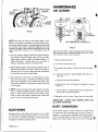
1. The tilling depth is controlled by the gauge wheals shown
above and to some extent by the adjusting screw and handle.
Refer to Figure 8. When deeper tilling is required, the gauge
wheels must be raised. Wheels must be lowered for shallower
tilling. Remove retainer spring from drilled rivet. Adjust·
gauge wheels up or down as desired and replace rivet and retainer spring.
2. Change engine oil after the first 5 hours of operation. Always drain the oil while engine is warm. Remove drain plug
at rear of engine and tilt Spader backward to completely
drain all old oil. Replace drain plug. Be sure Spader is level
and fill to overflowing with S.A.E. 30 motor oil, MS,SC,SD
or SE. Oil capacity: Approximately 2-3/4 pints.
7086R-20.1.75
I
TILLING DEPTH
5
I~-~
-.----
MAINTENANCE
RETAINER
SPRING
AIR CLEANER
GAUGE
-WHEEL
FIG.8
'\lOTE: Each hole will raise or lower gauge wheels 1 inch.
Spader can be levelled if necessary by turning adjusting screw
and handle, shown in Figure 7. The adjusting screw and handle
also control tilling depth. Shortening adjusting screw will
increase tilling depth, and lengthening adjusting screw will decrease tilling depth. However, try to keep Spader level at all
times.
CUP ASSEMBLED CORRECTLY
FIG.9
Clean and re-oil the air cleaner frequently (every few hours
under extremely dusty conditions). Clean and re-oil at least
every 25 hours under normal conditions.
2. The most efficient tillage is obtained when Spader engine is
fully loaded. The sound of Spader engine will tell you. When
Spader engine is lightly loaded, raise gauge wheels to increase tilling depth. If engine seems to be overloaded or
stalls out, lower gauge wheels for shallower tilling.
1. Remove wing nut and cover.
2. Lift off foam element from base.
3. Operate Spader engine at full throttle and operate tractor in
slowest forward speed, with tractor engine at idle speed or
just above idle. You will soon learn the proper combination
of tilling depth and speed for good tillage.
3. Push down. foam element as shown, and pull out cleaner
cup.
4. a. Wash foam element in liquid detergent and water to remove dirt.
4. Soil conditions will determine how deep Spader can penetrate on the first pass. In extremely hard ground, several
passes may be necessary to till to a depth of 6 inches, while
in soft ground, Spader may penetrate to a depth of 6 inches
in the first pass.
b. Wrap foam in cloth and squeeze dry.
c. Saturate foam with fresh engine oil. Squeeze to remove
excess oil.
5. NOTE: Tractors equipped with speed changer: It is necessary to purchase a slow-speed pulley to slow down ground
travel. If 3-point hitch does not have two holes in lever
crank on lever, drill another 17/32-inch hole in each lever
crank, % inch in from present hole center.
d. Put air-cleaner cup inside element. Be sure sealing lip is
over end -of cup (top and bottom).
5. Reassemble parts as shown. Screw wing nut down tight.
IMPORTANT: NEVER RUN ENGINE WITH AIR
CLEANER REMOVED..
DUSTY CONDITIONS
CULTIVATING
Set gauge wheels so that Spader will penetrate soil to a depth
of 2 to 3 inches. The Spader engine should be run at full throttle, except when cultivating small plants, a slower engine speed
is necessary to prevent burying the plants.
7086R-20.1.75
"Service engine regularly in dusty conditions. Air filter should
be cleaned every day and change engine oil every 15 hours of
operation. In extreme dusty conditions, clean air filter every 4
hours and change engine oil every 10 hours of operation. The ~\
service given engine greatly affects the life of the engine. ~!
6
o
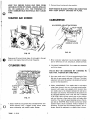
KEEP THE ENGINE CLEAN AI\ID FREE FROM
ACCUMULATIONS OF GRASS, LEAVES, SPILLED
01 L OR GASOLINE, ETC. THE PRESENCE OF
SUCH COMBUSTIBLE MATERIALS MAY CAUSE
FIRE.
2. Remove blower housing and clean regularly.
KEEP ENGII\IE IN GOOD OPERATING CONDITION
AND KEEP SAFETY DEVICES IN PLACE.
STARTER AIR SCREEN
CARBURETOR
IDLE-SPEED ADJUSTING SCREW
I
IDLE VALVE
FIG. 12
FIG. 10
Keep screen (A) around starter clean. Air is brought in through
screen to cool engine. Clean with a brush frequently.
1. Minor carburetor adjustment may be required to compensate for differences in fuel, temperature, altitude and load.
CYLINDER FINS
2. TO ADJUST CARBURETOR: Turn needle valve clockwise
until it just closes.
VALVE MAY BE DAMAGED BY TURI\lING IN
TOO FAR. TIGHTEI\I BY HAND OI\ILY.
3. Now open needle valve 1-118 turns counterclockwise. Close
idle valve in same manner and open 1-1/8 turns. This initial
adjustment will permit the engine to be started and warmed
up prior to final adjustment.
4. F.INAL ADJUSTMENT: Turn needle valve in until engine
misses (lean mixture), then turn it out past smooth-operating.point until engine runs unevenly (rich mixture). Now
turn needle valve to the midpoint between rich and lean so
the engine runs smoothly. Hold throttle at idle position and
set idle-speed adjusting screw until fast idle is obtained
(1750 RPM). Move throttle control lever to slow position
and turn idle valve in (lean) and out (rich) until engine idles
smoothly. Then reset idle-speed adjusting screw so that engine idles at 1750 RPM. Move throttle control lever to fast
position-engine should accelerate without hesitation or
sputtering. If engine does not accelerate properly, the carburetor should be readjusted to a slightly richer mixture.
FIG.11
I
~
I
o
1. Grass or chaff may clog system after prolonged service. Continued operation with a clogged cooling system causes
severe overheating and possible engine damage.
7086R -11.10.74
7
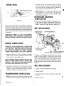
SPARK PLUG
operation). Remove fill plug (refer to Figure 71. located at
R.H. side of transmission. Oil level must be even with bottom of plug. Add oil, if necessary. Use S.A.E. 30 motor oil
for service, MS or equivalent. Replace fill plug.
y.030" FEELER GAUGE
2.
IMPORTANT: It is not necessary to change the oil in this
Spader transmission. If, for any reason, it must be changed,
oil capacity is 1 1/4 quarts of S.A.E. 30 motor oil for
service, MS or equivalent.
OUTBOARD BEARING
LUBRICATION
FIG. 13
1.
Clean and reset gap at .030 inch every 100 hours of operation.
Blast-cleaning of spark plugs in machines that use abrasive grit
is NOT recommended. Spark plugs should be cleaned by scraping or wire brushing and washing with a commercial solvent or
gasoline. Should spark plug need replacing, use Champion CJ-8
or equivalent.
There are two (2) grease fittings on your Spader. One
at each outboard bearing. Use Multipurpose Pressure Gun
Grease. Fill until grease comes out the inner end of
bearings. Grease every eight (8) hours. (Page 5, Fig. 7)
BELT ADJUSTMENT
RETAINER SPRING
DISENGAGE POWER TO ANY ATTACHMENT,
STOP ENGINE AND DISENGAGE SPARK PLUG
BEFORE MAKING REPAIRS OR ADJUSTMENTS.
ENGINE LUBRICATION
CHECK 01 L LEVEL REGULARLY-AFTER EACH
5 HOURS OF OPERATION. STOP ENGINE AND
WAIT SEVERAL MINUTES BEFORE CHECKING
OIL LEVEL. BE SURE OIL LEVEL IS MAli\!TAINED AND SPADER IS ON LEVEL GROUND.
LINK
CLUTCH LEVER
AND ARM
@
BELT GUARD REMOVED
FIG • 14 FOR ILLUSTRATION
1. Change oil after first 5 hours of operation. Thereafter,
change oil every 25 hours of operation. Remove oil drain
plug and drain oil while engine is warm.
The clutch is a belt-tightener type. Belts should be just tight
enough to prevent slippage. To tighten belts, remove retainer
spring securing belt-tightener link to lever and arm, and turn
link in a counterclockwise direction, when standing in front of
Spader, one turn at a time, until belts no longer slip. Belts that
are too tight stretch, require more H.P., and put more strain on
bearings.
NOTE: THE BEST TIME TO DRAIN OIL IS AT THE
END OF A DAY'S OPERATION, AT WHICH TIME
THE OIL IS HOT AND ALL DIRT AND FOREIGN
MATERIAL ARE SUSPENDED IN THE OIL.
BELT REPLACEMENT
2. Refill engine crankcase with oil as instructed on page 2.
Capacity: 2% pints. Nothing should be added to the recommended oil. Check oil level after each 5 hours of operation
and add oil, if necessary, to bring to correct level.
1. Remove three bolts holding belt guard to Spader.
2. Remove old belts.
TRANSMISSION LUBRICATION
1.
3. Install new belts so that lower sides of belts are above idler,
as shown.
NOTE: The oil/evel of the transmission should be checked
at the time of the initial engine oil change (after 5 hours of
7086R-20.1.75
4. Replace belt guard.
8
o
STORAGE
GENERAL
Engines to be stored over 30 days should be completely drained
offuel to prevent gum deposits forming on essential carburetor
parts, fuel filter, fuel lines and tank.
1. Just as your automobile needs professional mechanical
maintenance from time to time, so does your air-cooled
engine. Periodic replacement of the spark plug (every 100hrs)
is made necessary by NORMAL use.
1. Drain fuel tank completely and clean fuel filter.
2. Operate engine until gasoline in carburetor is completely
consumed.
2. Professional air-cooled-engine service is as close as your
nearest Sears service department.
3. While engine is still warm, drain oil from crankcase. Refill
with fresh 0 iI.
3. A yearly check-up or tune-up by a Sears service department
is a good idea to avoid breakdowns or delays. Do it each
fall; then, you're ready for spring. We even prepare it for
storage for you.
4. Remove spark plug, pour one ounce (2 or 3 tablespoons) of
S.A.E. 30 motor oil into cylinder and pull starter rope
slowly to distribute oil. Replace spark plug.
MAJOR REPAIRS SHOULD NOT BE ATTEMPTED
UNLESS YOU HAVE THE PROPER TOOLS AI\ID A
THOROUGH KNOWLEDGE OF THIS MACHINE.
5. Clean dirt and chaff from cylinder head fins, blower housing
and entire Spader.
IF ROTO-SPADER IS TO BE STORED FOR AN
EXTENDED PERIOD. EMPTY THE GASOLINE·
STORAGE CONTAII\lER, EITHER DISCARDING
THE GASOLlI\IE IN A SAFE PLACE OR USING IT
11\1 OTHER GASOLlNE·POWERED EQUIPMENT
FOR WHICH IT MAY BE SUITED.
Sears, Roebuck and Co. or Simpsons-Sears, Ltd. in Canada.re:
serves the right to make any changes in design or impr:ove~
ments without imposing any obligation to install the same
upon its items heretofore manufactured.
STORE YOUR SPADER INSIDE A DRY. WEATHER
·PROOF BUILDII\lG.
TO
i
7086R - 11.10.74
9
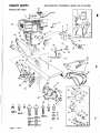
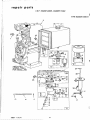
repair parts
ROTO-SPADER ATTACHMENT-MODEL NO. 917.251880
ENGINE AND TINES
-- -
...
56
50
49
~
),'
7086R -11.10.74
10
I
I
•
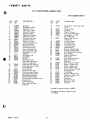
repair
parts
ROTO-SPADER ATTACHMENT-MODEL NO. 917.251880
ENGII\IE AI\ID TII\IES
~
ct
KEY
NO.
1
2
3
4
5
6
7
8
9
10
11
12
13
14
15
16
17
18
19
20
21
22
23
24
25
26
27
28
29
30
31
32
33
34
35
36
37
38
39
40
41
42
43
44
Ct
45
46
47
PART
NO.
DESCRIPTION
7093R
3468R
4012P
4914H
624A38
5015P
6678H
545P
3457R
6665H
4939M
6991A
6881R
634A707
634A702
9401H
3475R
1556P
6683H
4497H
2501P
4379H
634A60
6652H
6656H
634A718
1556P
5708H
634A563
3091P
1004P
501P
634A716
Throttle Control
Throttle Control Bracket
Street Elbow-Std. 900
Square Key 1/4 Sq.
Idler Arm Support and Pivot
E-Ring
U Bolt
*Gripco Crown Locknut 3/8-16
Lift Handle Extension
U Bolt Plate
Retainer Spring
Drilled R.H. Rivet
Clevis
Lift Link and Chain R.H.
Lift Link and Stop L.H.
Idler Arm
Idler Pulley
*Washer 13/32 x 7/8 x 14 Ga.
E-Ring
Retainer Spring
* Cotter Pin 5/32 xl
Handle Grip
Lever and Arm
Belt Retainer Link
Adjusting Pin
Belt Guard and Brackets
*Washer 13/32 x 7/8 x 14 Ga.
Scotchcal (Sears)
Set of 2 Matched V-Belts
*HexBolt3/8-16x 1 H.T.Grade5
* Lockwasher 3/8
*Hex Nut 3/8-16
Tine Shaft-Outer, Plate and
Shield
End Plate, Outer
7050R
7067R
Oil Seal
634A719
Outer Bearing and Seal
1003P
* Lockwasher 5/16
504P
*Hex Nut 5/16-18
Dust Cap and Grease Fitting
634A720
1306H
Roll Pin 1/4 x 1-1/2
Thrust Bearing Race
7396H
7094R
Gasket
7055R
Dust Shield
*Hex Bolt 5/16-18 x 1-1/4
3135P
Grade 5
6712H
Tine L.H.
6713H
Tine R.H.
4929H
Drilled Pan Hd. Rivet 3/8 x
1-3/4
7086R - 11.10.74
KEY
NO.
PART
NO.
48
49
3146R
634A556
50
51
52
53
54
55
56
57
58
59
60
61
A
B
C
D
E
F
G
H
DESCRIPTION
Retainer Spring
Tine Plate and Hub L.H. (Less
Tines)
634A557
Tine Plate and Hub R.H. (Less
Tines and Outer Tine Plate)
3467R
Tine Shield
3471R
Engine Sheave
706'IR
Engine Base Strap
634A717
Hitch Plate Weldment
684'1 R
Scotchcal 8 H.P.
634A714
Engine 8 H,P. Briggs and
Stratton 190402
1002P
* Lockwasher 1/4
1000P
* Lockwasher 1/2
1511P
*Washer 3/8 x 7/8 x 14 Ga.
508P
*Hex Jam l\Iut 3/8-16
1537P
*Washer 11/32 x 11/16 x 16 Ga.
503P
* Hex I\lut 1/4-20
3234P
* Hex Bolt 1/2-20 x 3/4
453'IP
* Hex Socket Hd less. Set Screw
5/16-18 x 3/8
56P
Plow Bolt 5/16-18 x 2
44P
Plow Bolt 3/8-16 x 1-1/4
3028P
*Hex Bolt 3/8-16 x 1-3/4
6024P
Hex Bolt w/Ext. Tooth Lockwasher 5/16-18 x 3/4
3010P
*Hex Bolt 5/16-18 x 3/4
Owner's Manual
7086R
OPTIONAL EQUIPMENT
(NOT ILLUSTRATED)
3567H
6109H
3568H
5352Hl
5559H
Slow Speed Engine Pulley for 1"
Dia. Shaft
Slow Speed Engine Pulley for
1-1/8" Dia. Shaft
V-Belt for 3567H or 6109H
Slow Speed Engine Pulleys
Slow Speed Engine Pulley for
3-Speed Custom Tractor
V-Belt for 5352Hl Engine
Pulley
*STANDARD HARDWARE--PURCHASE LOCALLY
11
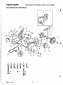
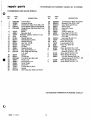
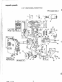
repair parts
ROTO-SPADER ATTACHMENT-MODEL NO. 917.251880
TRANSMISSION AND GAUGE WHEELS
1
.
36
12
38
12
121~~
"'~, ~
37~ )";:~
G
\1
@41
@39
®40
70B6R - 11.10.74
@43
@43
~35
12
•
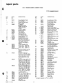
repair
parts
'- ROTO-SPADER ATTACHMENT-MODEL NO. 917.251880
TRANSMISSION AND GAUGE WHEELS
~O
~
.
I
KEY
NO.
r
1
2
3
4
5
I
6
7
8
9
10
11
12
13
14
15
16
17
18
~e
19
20
21
22
23
24
25
26
27
28
PART.
NO.
KEY
NO.
DESCRIPTION
634A562
4939M
4929H
634A61
634A559
Transmission
Retainer Spring
Drilled Pan Head Rivet 3/8 x 3/4
Gauge Wheel Sleeve and Brackets
Gauge Wheel Adjusting Shaft and
Brackets
Wheel
3474R
Shoulder Bolt
4898H
*Washer 13/32 x 13/16 x 11 Ga.
1557P
514P
* Locknut
Needle Bearing
3136R
Needle Bearing Shell
6677H
Needle Bearing
4895H
Hex Nut 1/2-20
9204H
Input Sheave
3472R
Oil Seal
4910H
Needle Bearing
4896H
Gear Case Shield L.H.
4877H1
Gear Case and Bearings
624A56
L.H. Half
Gasket
2601R
Thrust Cap
4870H
Ti ne Shaft and Sprocket
634A555
Roller Link
4950H
Connecting Link
4949H
Roller Chain
2600R
Dowel Pin
9880M
Thrust Bearing Race
1370H
Gasket
4912H
2nd Reduction Shaft and Gears
634A59
PART
NO.
29
30
31
32
33
34
35
36
37
634A58
9858Ml
634A57
5855H
6672H
4913H
1685H
4002P
624A57
38
39
40
41
42
43
A
B
4878H1
1004P
501P
1003P
504P
7850H
3030P
5586P
C
D
E
3010P
3015P
5585P
F
G
3018P
3008P
DESCR IPTION
1st Reduction Shaft and Gears
Woodruff Key 3/16 x 5/8
Input Shaft and Pinion
Relief Valve
Gear Sh ift Cover
Gasket
Locknut 5/16-18
Pipe Plug 1/2 14 N.P.T.
Gear Case and Bearings
R.H. Half
Gear Case Shield R.H.
* Lockwasher 3/8
* Hex Nut 3/8-16
* Lockwasher 5/16
*Hex Nut 5/16-18
Spacer
*Hex Bolt 3/8-16 x 2-1/4
Hex Hd. Roll Lok Tapping
Screw 5/16-18 x 1-1/2
*Hex Bolt 5/16-18 x 3/4
*Hex Bolt 5/16-18 x2
Flat Hd. Slotted Roll Lok
Tapping Screw 5/16-18 x 1-1/2
*Hex Bolt 5/16-18 x 6
*Hex Bolt 5/16-18 x 1/2
* STANDARD HARDWARE--PURCHASE LOCALLY
7086R - 11.10.74
13
r~~
~-~----
repair parts
8 H.P. ENGINE MODEL NUMBER 190402
TYPE NUMBER 0858-01
~
1
W.QJ
~~ 9
cifr~.
-10
1~~
r---:--, ""'- -
13
I
i
II
Ii
* REOUIRES
12.
SPECIA L TOOLS
FOR INSTALLING
a-e
!
26
R
:::::::::;;;~:;:=:===:::::Z:1I
A
\\
\
c::<
\
65
7086R - 11.10.74
66
6~
14
l
....
-
11-
Q
•
repair
parts
8 H.P. ENGINE MODEL NUMBER 190402
{O
TYPE NUMBER 0858-01
KEY
NO.
1
2
3
4
5
6
7
8
9
10
11
12
13
15
16
17
18
221907
221935
69221
290816
221468
280001
270093
390400
230318
22547
99665
295984
"298683
*68477
295913
296005
291367
91257
19
20
21
22
90970
93535
294606
295962
23
24
295938
93038
25
26
27
28
29
30
31
32
33
34
62940
67218
298826
t 27918
390503
23108
t 292681
61967
93043
390404
T4
e
PART
NO.
DESCRIPTION
Clip-Wire
Bracket-Fuel Tank
Cap-Fuel Tank
Tank Assy. - Fuel
Cover-Air Cleaner
Cup-Air Cleaner
Element-Air Cleaner
Cleaner Assy.-Air
Connector-Fuel Pipe
Screen-Fuel Filter
Yoke-Fuel Filter
Filter Assembly-Fuel
Bowl-Fuse Fi Iter
Gasket-Fuel Filter
Valve-Fuel Shut-off
Cover Assembly-Fuel
Strap Assy.-Fuel Tank
Screw-Mach. Fi \. Hd.
~-20 x 1Y2
Nut-Square ~-20
Screw-Sems
Seal-Oi I
Bushing-Cylinder
Note: Requires special
tools for installation
Carburetor Over Hau I Kit
Screw-Throttle and Choke
Valve Mfg. Sem
Va Ive-Throttle
Connector-Fuel Pipe
Shaft and Lever-Thrott!e
Gasket-Carburetor Body
Body-Upper Carburetor
Bushing-Throttl e Shaft
Valve Assembly-Carburetor Idle
Stop-Throttle
P in-Throttle Stop
Body Assemb Iy-Upper
Carburetor
KEY
NO.
PART
NO.
35
91920
36
37
38
39
40
26157
93453
230768
390311
90746
41
92290
42
43
44
45
46
47
48
49
50
51
t 230896
99333
299096
t 390395
t 68667
23117
68677
23118
230009
220521
52
53
27590
390403
54
55
56
57
58
298875
62899
26155
23123
93038
59
60
61
62
63
64
65
66
62872
222150
66648
92129
93158
390323
93053
299942
DESCRIPTION
. Screw-Mach. Fi I. Hd. No. 8-32
x 5/8
Spring-Throttl e
Nut-Wing
Stud-Air Cleaner
Pipe Assy.-Air Cleaner
Screw-Mach., Fi I. Hd.
No. 10-32 x 5/8
Wa sher-Lock No. 1() x
1116 x 3/64
Pin-Float Hinge
Float-Carburetor
Valve-Fuel Inlet
Nozz Ie-Carburetor
Gasket-Nozz Ie
Retainer, Needle Valve
Packing, Needle Valve
Nut, Needle Valve Packing
Valve Needle
Reta iner-Ca rburetor
Drain Filter
FiIter-Ca rbu retor Dra in
Body As sy.-Lower
Carburetor
Shaft And Lever Choke
Washer - Choke Lever
Spring - Choke Lever
Screw - Choke Lever
Screw-Throttle and Choke
Va Ive Mtg. Sem
Va Ive-Choke
Strap-Air Cleaner Pipe
Gasket-Air Cleaner Stud
Nut-Hex ~-28
Screw-Sem
Carburetor Assy.
Clamp-Fuel Pipe
Pipe-Fuel
*Included in gasket set part no. 299577
t Included incarburetor overhaul kit part
no. 295938
7086R -11.10.74
15
r.---~----------
repair parts
8 H.P. ENGINE MODEL NUMBER 190402
TYPE NUMBER 0858-01
(
~~vl 3_~ 4~~ I()C (~
,-----,--__1
9
rmm~~~
5
7
8
~
17~
18
19~
(
I
'I'
(
50
\!)
())~
)~""'-J!,"
0
.. REQU IRES 38
SPECIAL TOOLS
FOR INSTALLING
I 68
GASKET SET I
16
repair parts
8 H.P. ENGINE MODEL NUMBER 190402
TYPE NUMBER 0858·01
KEY
NO;
PART
NO.
DESCRIPTION
Screw-C~I inder Head
(2-9/32 ong)
Screw- Cyl inder Head
93211
(2-9/16 long)
Plug-Spark
298809
Note: Spark plugs
298809 use ignition
cable terminal no.
221798
Locknut- Muffler
91242
Muffler-Exhaust
390578
Valve-Intake
261055
Valve-Exhaust
390419
Retai ner- Exhau st
93630
Valve Rotocoil (2)
Cover-Cylinder Head
221901
Head-Cyl inder
211778
Gasket-Cylinder Head
* 270430
Rod Assy.-Connecting
390~01
Note: For connecting rod
with .020" undersize
crankpin bore-order no.
390773
Piston Assembly Std.
390347
Piston Assy..010" 0.5.
390348
Piston Assy ..020" 0.5.
390349
Piston Assy ..030" 0.5.
390350
Piston ring sets
Note: For chrome ring set
standard size order no.
299743
Ring Set-Pi ston-std.
299569
Consists of 211637 piston
ring compo top std. 211636
piston ring compo center
std. 211635 piston ring
oil std.
Ring Set-Piston-.Ol0" 0.5.
299570
Consists of 211649 piston
ring compo top .010" 0.5.
211650 piston ring compo
center .010" 0.5. 211651
piston ring oil .010" 0.5.
Ring Set-Piston-030" 0.5.
299572
Consists of 211657 piston
ring compo top .030" 0.5.
211658 piston ring compo
center .030" 0.5. 211659
pi ston ring oi I .030" 0.5.
Lock-Piston Pin
68546
Pin Assy.-Piston-Std.
295840
Pin Assy.-Piston .005" 0.5.
295841
Dipper-Connecting Rod
222113
Lock-Conn. Rod Screw
222114
Screw-Connecting Rod
92659
Screw-Cylinder Shield
93163
Mtg.Sem.
Shield-Cylinder
221898
93210
2
3
4
5
6
7
8
e
9
10
11
12
13
14
,e
15
16
17
18
19
20
21
7nR~R - 11 1074
KEY
NO.
PART
NO.
DESCRIPTION
22
23
24
26828
65906
93208
25
93128
Spring-Exhaust Valve
Spring-Intake Valve
Screw-Intake Elbow
Mounting Sem.
Screw-Carburetor
Mounting Sem.
Elbow-Intake
Gasket-Intake Elbow
Gasket-Intake Elbow Mtg.
Retainer-Intake Valve
Gasket-Valve Cover
Rotoco iI-Exhaust Valve
Crankshaft
Gasket-Crankcase cover
1164" thick
Gasket- Crankcase cover
.005" thick
Gasket-Crankcase cover
.009" thick
Cover Assy.-Crankcase
Seal-Oil
Plug-Oil Filler
Bush ing-Crankcase Cover
Note: Requires special
too! s for installation
Screw-Crankcase cover
mounting sem.
Tappet-Valve
Bu sh ing-Governor Shaft
Cyl inder Assembly
Link-Governor
Breather Assembly
Screw-Sem
Tube- Breather
Wire-Ground
PIate-Governor Contro I
Clamp-Casing
Screw-Sem.
Screw-Sem.
Lever Assy.-Governor
Bolt-Governor Lever
Switch-Stop
Spring-Governor
Plug-Oil Drain
Cotter-Hair Pin
Crank-Governor
Washer-Spacer
Washer
Nut-Hex 10-24
Retainer-E-Ring
Gear-Governor
Washer-Thrust
Gear-Cam
Gasket Set
26
27
28
29
30
31
32
33
211812
* 270684
* 27828
221596
* 27803
292260
261077
* 27750
* 27876
* 27877
34
35
36
37
299167
298423
66768
295964
38
93585
39
40
41
42
43
44
45
46
50
51
52
53
54
55
56
57
58
59
60
61
62
63
64
65
66
67
68
260933
230843
390399
260872
390321
93536
67068
299500
390670
221535
93496
93535
299165
92613
297472
261194
91084
93306
230842
221559
220680
90356
93307
297656
221551
210728
299577
* Included in gasket set Part no. 299577
17
'
I
r~
I
repair
pa;~
,
8 H.P. ENGINE MODEL NUMBER 190402
TYPE NUMBER 0858-01
1
a(1
3
'~~1--18
17
13
KEY
NO.
pART
DESCRIPTION
KEY
NO.
PART
NO.
DESCRIPTION
Screw-Sem.
Screw-Sem.
CIamp- Conden ser
Spring-Connector
Spring-Breaker Arm
Guide-Air
Armature Assembly
Screw-Armature Mtg.
Sem
Plunger-Breaker Point
Screw-Breaker Arm
Mounting Sem
Breaker points and conden ser set. Note: 299061
ignition kit includes
294628 point set 65704
plunger and 61760 keyflywheel.
Housing- Blower
Screen-Rewind Starter
Washer-Ratchet Sealing
Ball-Clutch
Clutch Assy.-Rewind
Starter
Flywheel-Magneto
Screw-Sem
19
20
21
22
222117
61760
220865
221383
23
66718
24
298799
25
26
221653
93067
27
28
29
30
31
32
33
295871
260414
295001
295272
221014
68848
93254
34
35
36
37
38
66728
230543
230228
66564
294303
Cover-Breaker Point
Key-Flywheel
Washer-Spring
Housing-Rewind Starter
Clutch
Washer-Starter Clutch
Thrust
Rachet-Rewind Starter
Clutch
Washer-Retoiner
Screw-Rewind Starter
Housing Mtg. Sem.
Pulley-Rewind Starter
Spring-Rachet
Starter Assy.-Rewind
Housing-Rewind Starter
Anchor-Spri ng
Bumper-Starter Pulley
Screw-Pulley Bumper
Mounting
Grip-Starter Rope
Adapter-Rachet Spring
Pin-Starter Grip
Rope-Rewind Starter
Spring-Rewind Starter
NO.
1
2
3
4
5
6
7
8
93158
93042
220477
260374
26018
221760
298968
93381
9
10
65704
93381
11
294628
12
13
14
15
16
299853
221796
68238
63770
298798
17
18
298260
93014
(
The Model Number will be found on a plate attached to theR.H.
side of the transmission. Always mention the Model Number
when requesting service or repair parts for your ROTO-SPADER
ATTACHMENT
All parts listed herein may be ordered from any SEARS, ROEBUCK
AND CO. or SIMPSONS-SEARS LIMITED retail or catalog store.
ISears I
WHEN ORDERING REPAIR PARTS, ALWAYS GIVE THE FOLLOWING INFORMATION:
.
owners
manoal
1.
PART NUMBER
3.
PART DESCRIPTION
2.
MODEL NUMBER
4.
NAME OF MERCHANDISE
If the parts you need are not stocked locally, your order will be
electronically transmitted to a Sears Repair Parts Distribution
Center for "expedited handling".
MODEL NO.
When you buy merchandise
from Sears you get an extra
something that nobody else
can offer . . . Sears Service
911.251880
d.
H,ow to Order
Repair Parts
335-1J~9
337:;
L' J.-3
Original Document Scan
Provided By:
WheelHorse.Org