1
Installation
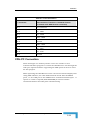
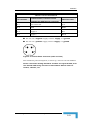
Table 2-3: J21 Pin Connections
J 21 Connector
4-PIN Connector, Function = Power
Cable Core color
(viewed at the GPS Receiver connector)
Pin 1
Not Connected
N/A
Pin 2
GND
White
Pin 3
Supply +
Red
Pin 4
Supply -
Black
For use on a negative supply connect ‘supply +’ to ground.
For use on a positive supply connect ‘supply -‘ to ground.
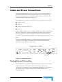
Figure 2-13: Female Power Connector (cable end view)
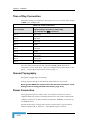
The maximum power dissipated, at warm-up, does not exceed 20Watts.
Power connection wiring should be as short as is practicable, and
not shared with heavy current or intermittent devices such as
motors, starters, etc.
GPS Timing Receiver Installation and Operation Manual
2-21