1
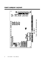
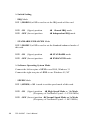
Independent IRQ Mode (JP11-JP14)
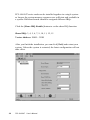
In this mode, each of the four ports can have IRQ channels set
individually. For each port, select an IRQ which is not already in use
by another card in the system. The mapping of jumpers to ports is as
shown below.
Port 1 à JP11
Port 2 à JP12
Port 3 à JP13
Port 4 à JP14
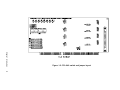
Shared IRQ Mode (JP11)
Select an IRQ which is not already in use by another card in the
system. If you are installing more than one PCL-846/847, set them to
different IRQ numbers. Jumper Bank JP11 controls the card IRQ.
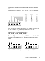
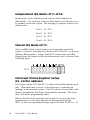
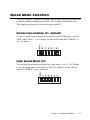
Simply place the jumper on the desired interrupt level as shown in the
following figure.
JP 11
Interrupt Status Register Setup
(S2, Vector address)
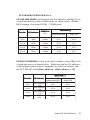
This feature on the PCL-846/847 is utilized in the IRQ sharing mode
only. When data arrives at one of the four ports, it generates an
interrupt in the interrupt register. The PC software can read this, and
identify immediately which port generated the interrupt. This saves
time, and makes programming easier.
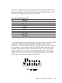
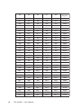
When a data bit of the interrupt status register is set to 0, the corresponding port is selected to generate an interrupt in DOS and
WIN 3.x, the corresponding interrupt register for Win 95/NT is 1. If
14
PCL-846/847 User's Manual