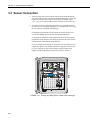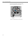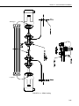
1
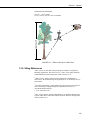
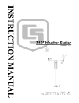
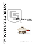
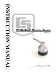
UT10 Weather Station
Revision: 7/10
C o p y r i g h t © 1 9 9 3 - 2 0 1 0
C a m p b e l l S c i e n t i f i c , I n c .
Warranty and Assistance
The UT10 WEATHER STATION is warranted by Campbell Scientific, Inc.
to be free from defects in materials and workmanship under normal use and
service for twelve (12) months from date of shipment unless specified
otherwise. Batteries have no warranty. Campbell Scientific, Inc.'s obligation
under this warranty is limited to repairing or replacing (at Campbell Scientific,
Inc.'s option) defective products. The customer shall assume all costs of
removing, reinstalling, and shipping defective products to Campbell Scientific,
Inc. Campbell Scientific, Inc. will return such products by surface carrier
prepaid. This warranty shall not apply to any Campbell Scientific, Inc.
products which have been subjected to modification, misuse, neglect, accidents
of nature, or shipping damage. This warranty is in lieu of all other warranties,
expressed or implied, including warranties of merchantability or fitness for a
particular purpose. Campbell Scientific, Inc. is not liable for special, indirect,
incidental, or consequential damages.
Products may not be returned without prior authorization. The following
contact information is for US and International customers residing in countries
served by Campbell Scientific, Inc. directly. Affiliate companies handle
repairs for customers within their territories. Please visit
www.campbellsci.com to determine which Campbell Scientific company
serves your country.
To obtain a Returned Materials Authorization (RMA), contact Campbell
Scientific, Inc., phone (435) 753-2342. After an applications engineer
determines the nature of the problem, an RMA number will be issued. Please
write this number clearly on the outside of the shipping container. Campbell
Scientific's shipping address is:
CAMPBELL SCIENTIFIC, INC.
RMA#_____
815 West 1800 North
Logan, Utah 84321-1784
For all returns, the customer must fill out a “Declaration of Hazardous Material
and Decontamination” form and comply with the requirements specified in it.
The form is available from our website at www.campbellsci.com/repair. A
completed form must be either emailed to [email protected] or faxed to
435-750-9579. Campbell Scientific will not process any returns until we
receive this form. If the form is not received within three days of product
receipt or is incomplete, the product will be returned to the customer at the
customer’s expense. Campbell Scientific reserves the right to refuse service on
products that were exposed to contaminants that may cause health or safety
concerns for our employees.
UT10 Table of Contents
PDF viewers note: These page numbers refer to the printed version of this document. Use
the Adobe Acrobat® bookmarks tab for links to specific sections.
1. General ......................................................................1-1
1.1 Installation Tasks .................................................................................. 1-1
1.1.1 Indoors ........................................................................................ 1-1
1.1.2 Outdoors...................................................................................... 1-1
1.2 Tools Required ..................................................................................... 1-2
1.2.1 Tools for Tower Installation ....................................................... 1-2
1.2.2 Tools for Instrumentation and Maintenance ............................... 1-2
1.2.3 Supplies for Power and Communications Options ..................... 1-3
1.3 Siting and Exposure.............................................................................. 1-3
1.3.1 Wind Speed and Direction .......................................................... 1-3
1.3.2 Temperature and Relative Humidity........................................... 1-3
1.3.3 Precipitation ................................................................................ 1-4
1.3.4 Solar Radiation............................................................................ 1-4
1.3.5 Soil Temperature......................................................................... 1-4
1.3.6 Siting References ........................................................................ 1-5
1.4. Specifications....................................................................................... 1-6
2. UT10 Tower Installation ...........................................2-1
2.1 UT10 Tower Installation....................................................................... 2-1
2.1.1 Base Installation.......................................................................... 2-1
2.1.2 Tower Installation ....................................................................... 2-3
2.1.3 UT10 Tower Grounding ............................................................. 2-4
2.2 Sensor Mounting Brackets.................................................................... 2-5
2.2.1 Crossarm Mounting .................................................................... 2-5
2.2.1.1 CM202, CM204, CM206 Crossarms ................................ 2-5
2.2.1.1 019ALU Crossarm ............................................................ 2-5
2.2.2 Gill Radiation Shields (41303-5A, 41003-5, 41005-5) .............. 2-6
2.2.3 CM225 Pyranometer Stand......................................................... 2-7
3. Instrumentation Installation.....................................3-1
3.1 Enclosure, Datalogger, Power Supply .................................................. 3-1
3.1.1 Enclosure .................................................................................... 3-1
3.1.2 Datalogger and Power Supply .................................................... 3-3
3.1.3 BPALK Alkaline Power Supply ................................................. 3-3
3.1.4 PS100 Rechargeable Power Supply............................................ 3-4
3.1.5 Solar Panel .................................................................................. 3-4
3.2 Sensor Connection................................................................................ 3-6
3.3 Communication and Data Storage Peripherals ..................................... 3-7
3.3.1 CFM100, NL115, or NL120 ....................................................... 3-7
3.3.2 COM220 Phone Modems ........................................................... 3-7
3.3.3 Cellular Transceivers .................................................................. 3-8
3.3.4 SRM-5A Rad Modem and SC932A Interface ............................ 3-9
3.3.4.1 SRM-5A at the Datalogger................................................ 3-9
3.3.4.2 SRM-5A at the Computer.................................................. 3-9
i
UT10 Table of Contents
3.3.5 RF500M RF Modem and RF310-Series Transceivers .............. 3-12
3.3.5.1 RF500M Modem Configuration ...................................... 3-12
3.3.5.2 RF500M RF Base Station................................................ 3-13
3.3.5.3 Install Nearest Repeater/Field Station ............................. 3-14
3.3.6 MD485 Multidrop Interface ...................................................... 3-14
3.3.6.1 MD485 Multidrop Interface at the Datalogger ................ 3-14
3.3.6.2 MD485 Multidrop Interface at the Computer.................. 3-15
3.4 Sealing and Desiccating the Enclosure ............................................... 3-15
4. Sensor Installation................................................... 4-1
4.1 034B Met One Windset ........................................................................ 4-1
4.2 05103, 05103-45, 05106, and 05305 RM Young Wind Monitors........ 4-2
4.3 03002 RM Young Wind Sentry Wind Set ............................................ 4-3
4.3.1 03002 Mounted to the Mast ........................................................ 4-3
4.3.2 03002 Mounted to CM202, CM204, or CM206 Crossarm ......... 4-3
4.4 Licor Silicon Radiation Sensors (LI200X, LI200S, LI190SB)............. 4-4
4.5 107/108 Temperature Probe.................................................................. 4-4
4.6 107/108 Soil Temperature Probe .......................................................... 4-6
4.7 HMP50 Vaisala Temperature and RH Probe ........................................ 4-6
4.8 HMP45C/HMP35C Vaisala Temperature and RH Probe ..................... 4-8
4.9 CS100 or CS106 Barometric Pressure Sensor ...................................... 4-9
4.10 Texas Electronics Tipping Bucket Rain Gages (TE525, TE525WS,
TE525MM)....................................................................................... 4-9
4.11 TB4, TB4MM or CS700 Rain Gage ................................................. 4-10
4.12 SR50A Sonic Ranging Sensor .......................................................... 4-11
4.12.1 Beam Angle............................................................................. 4-11
4.12.2 Mounting Height ..................................................................... 4-11
4.12.2.1 Reference Point ............................................................. 4-12
4.12.3 Mounting Options ................................................................... 4-12
4.13 CS616 Water Content Reflectometer................................................ 4-14
4.14 237 Leaf Wetness Sensor.................................................................. 4-15
4.15 257 Soil Moisture Sensor.................................................................. 4-16
4.16 CS210 Enclosure Humidity Sensor................................................... 4-17
4.17 Wind Direction Sensor Orientation................................................... 4-17
4.17.1 Determining True North and Sensor Orientation .................... 4-17
4.17.2 National Geophysical Data Center Web Site .......................... 4-18
5. Standard Software Installation ............................... 5-1
5.1 Datalogger Program ................................................................................. 1
5.2 Weather Station or Datalogger Support Suite.......................................... 1
5.3 Quick Start Review .................................................................................. 1
6. Maintenance and Troubleshooting......................... 6-1
6.1 Maintenance.......................................................................................... 6-1
6.1.1 Instrumentation Maintenance ...................................................... 6-1
6.1.2 Batteries....................................................................................... 6-1
6.1.3 Desiccant ..................................................................................... 6-2
6.1.4 Sensor Maintenance .................................................................... 6-2
6.2 Troubleshooting .................................................................................... 6-3
6.2.1 No Response Using the Keypad.................................................. 6-3
6.2.2 No Response from Datalogger through SC32B or Modem
Peripheral................................................................................. 6-3
ii
UT10 Table of Contents
6.2.3 NaN Displayed in a Variable ...................................................... 6-4
6.2.4 Unreasonable Results Displayed in a Variable ........................... 6-4
Figures
1.3-1.
2.1-1.
2.1-2.
2.1-3.
2.1-4.
2.1-5.
2.2-1.
2.2-2.
Effect of Structure on Wind Flow .................................................... 1-5
UT10 Weather Station...................................................................... 2-2
UT10 Tower and Concrete Foundation............................................ 2-2
Concrete Foundation and Anchor Bolts ........................................... 2-3
UT10 Mast........................................................................................ 2-4
Tower Grounding ............................................................................. 2-5
Top View of Tower .......................................................................... 2-6
CM210 crossarm-to-pole bracket (top) is included with the
crossarm for attaching the crossarm to the tower’s mast or leg.... 2-6
2.2-3. 019ALU Crossarm and Lightning Rod ............................................ 2-7
2.2-4. CM225 Solar Radiation Mount with a LI2003S Leveling Base
and LI200X Solar Radiation Sensor............................................. 2-8
2.2-5. CM225 Attached to a Mast .............................................................. 2-8
3.1-1. Enclosure brackets configured for a tower mount............................ 3-2
3.1-2. This exploded view shows the components of a “-TM” bracket
option............................................................................................ 3-2
3.1-3. An enclosure attached to two tower legs.......................................... 3-3
3.1-4. CR1000 and PS100 Mounted to an Enclosure Backplate ................ 3-5
3.1-5. SP10 Solar Panel .............................................................................. 3-5
3.2-1. Routing and Wiring Sensor Leads to the Datalogger....................... 3-6
3.3-1. The NL115 connects to the CR1000’s peripheral port allowing
data to be stored on removable Compact Flash cards................... 3-7
3.3-2. COM220 Modem with Surge Protector ........................................... 3-8
3.3-3. SRM-5A Rad Modem and SC932A Interface................................ 3-10
3.3-4. SRM-5A Wiring............................................................................. 3-11
3.3-5. You can configure any two types of interface ports (RS-485,
RS-232, and CS I/O) to be used at a time................................... 3-15
3.4-1. Enclosure Supply Kit ..................................................................... 3-16
4.1-1. Met One 034B Wind Speed and Direction Sensor........................... 4-1
4.2-1. 05103 RM Young Wind Monitor..................................................... 4-2
4.3-1. 03002 Mounted to a CM200-series Crossarm.................................. 4-3
4.4-1. LI200X/LI200S/LI190SB and LI2003S Leveling Fixture ............... 4-4
4.5-1. 107 Temperature Probe .................................................................... 4-5
4.7-1. HMP50 Temperature and RH Probe ................................................ 4-7
4.8-1. HMP45C Vaisala Temperature and RH Probe................................. 4-8
4.10-1. TE525 Texas Electronics Rain Gage.............................................. 4-9
4.11-1. TB4 or TB4MM Mounted onto a CM310 Pole via the CM240
Mount ......................................................................................... 4-10
4.12-1. Beam Angle Clearance ................................................................. 4-11
4.12-2. Distance from Edge of Transducer Housing to Grill.................... 4-12
4.12-3. SR50A Mounted to a Crossarm via the 19517 Mounting Kit ...... 4-13
4.12-4. The SR50A Mounted to the Crossarm Shown from Another
Angle .......................................................................................... 4-13
4.12-5. SR50A - Mounted using Nurail and C2151 Mounting Stem ....... 4-14
4.13-1. CS616 Water Content Reflectometer with #14383 Probe
Insertion Guide ........................................................................... 4-15
4.14-1. 237 Leaf Wetness Sensor ............................................................. 4-15
4.15-1. 257 Soil Moisture Sensor ............................................................. 4-16
4.16-1. CS210 Installed on a CR1000 ...................................................... 4-17
4.17-1. Magnetic Declination for the Contiguous United States .............. 4-18
iii
UT10 Table of Contents
4.17-2. Declination Angles East of True North are Subtracted from 0
to get True North ........................................................................ 4-19
4.17-3. Declination Angles West of True North are Added to 0
to get True North ........................................................................ 4-19
iv
Section 1. General
This section provides preparation and siting information as well as specifications.
1.1 Installation Tasks
1.1.1 Indoors
•
Immediately upon receipt of your shipment…
⇒ Open shipping cartons.
⇒ Check contents against invoice. Contact CSI immediately about any
shortages.
•
Several days prior to the planned installation date…
⇒ Collect tools and site information (Section 1)
⇒ Assemble datalogger, communications device, and power supply in
enclosure (Section 3)
⇒ Install datalogger support software on PC (Section 5)
⇒ Establish communications between the datalogger and the PC
⇒ Program datalogger, test sensors, and retrieve data
⇒ Trial run the tower / tripod installation, assembling as much as
possible (Section 2)
⇒ Repackage equipment for transport to the field site
1.1.2 Outdoors
•
Locate suitable site (Section 1)
•
Prepare tower base (Section 2)
⇒ Raise tower (Section 2)
⇒ Install instrumentation enclosure (Section 3)
⇒ Install sensors (Section 4)
1-1
Section 1. General
1.2 Tools Required
Tools required to install and maintain a weather station are listed below.
1.2.1 Tools for Tower Installation
Shovel
Rake
Open end wrenches: 3/8", 7/16", ½", (2) 9/16"
Magnetic compass
6' Step ladder
Tape measure (12' and 20')
Nut driver (3/8")
Level (24" to 36")
Pick or digging bar
Claw hammer
Materials for concrete form:
Hand Saw
(4) 2" x 4" x 8' piece of lumber
(8) 8 p double-head nails
(8) 16 p double-head nails
concrete trowels
(2) 1" to 1.5" thick x 24" boards to support base above forms (optional)
concrete
1.2.2 Tools for Instrumentation and Maintenance
Lock and key for enclosure
Magnetic declination angle (Section 4)
Magnetic compass
Straight bit screwdrivers (small, medium, large)
Phillips-head screwdrivers (small, medium)
Small diagonal side-cuts
Needle-nose pliers
Wire strippers
Pocket knife
Calculator
Volt / Ohm Meter
Electrical Tape
Step ladder (6')
Station manuals
Station log and pen
Open end wrenches: 3/8", 7/16", ½", (2) 9/16"
Socket wrench and 7/16" deep well socket
Adjustable wrench
Pliers
Conduit and associated tools (as required)
Felt-tipped marking pen
Claw hammer
Pipe wrench (12")
Tape measure (12' to 20')
3/8" nut driver
Level (24" to 36")
Teflon tape or pipe dope
5/64" Allen hex wrench
1-2
Section 1. General
1.2.3 Supplies for Power and Communications Options
AC Power
Wire, conduit, and junction boxes as needed
Phone Modem
Hayes compatible calling modem for PC
Phone line to weather station or junction box
Short-Haul Modem
4 Conductor communications cable from PC to weather station or junction box
6' copper ground rod and clamp for PC surge protection (optional)
1.3 Siting and Exposure
CAUTION
If any part of the weather station comes in contact with
power lines, you could be killed. Contact local utilities for
the location of buried utility lines before digging or driving
ground rods.
Selecting an appropriate site for the weather station is critical in order to obtain
accurate meteorological data. In general, the site should be representative of
the general area of interest, and away from the influence of obstructions such
as buildings and trees.
The weather station should not be located where sprinkler irrigation water will
strike sensors or instrument enclosure.
Some general guidelines for site selection are listed below, which were
condensed from EPA (1988)1, WMO (1983)2, and AASC (1985)3 publications.
1.3.1 Wind Speed and Direction
Wind sensors should be located over open level terrain, and at a distance of at
least ten times (EPA) the height of any nearby building, tree or other
obstruction, as illustrated in Figure 1.3-1.
Standard measurement heights:
3.0 m ± 0.1 m recommended (AASC)
2.0 m ± 0.1 m, 10.0 m ± 0.5 m optional (AASC)
10.0 m (WMO and EPA)
1.3.2 Temperature and Relative Humidity
Sensors should be located over an open level area at least 9 m (EPA) in
diameter. The surface should be covered by short grass, or where grass does
not grow, the natural earth surface. Sensors should be located at a distance of
at least four times the height of any nearby obstruction and at least 30 m (EPA)
from large paved areas. Sensors should be protected from thermal radiation,
and adequately ventilated.
1-3
Section 1. General
Situations to avoid include:
•
•
•
•
•
•
•
•
•
large industrial heat sources
rooftops
steep slopes
sheltered hollows
high vegetation
shaded areas
swamps
areas where snow drifts occur
low places holding standing water after rains
Standard measurement heights:
1.5 m ± 1.0 m (AASC)
1.25 - 2.0 m (WMO)
2.0 m temperature (EPA)
2.0 m and 10.0 m for temperature difference (EPA)
1.3.3 Precipitation
A rain gage should be sited on level ground that is covered with short grass or
gravel. In open areas, the distance to obstructions should be two to four times
(EPA, AASC) the height of the obstruction.
The height of the opening should be as low as possible, but should be high
enough to avoid splashing from the ground. Wind shields, such as those used
by the National Weather Service, are recommended for open areas.
Collectors should be heated, if necessary, to properly measure frozen
precipitation. The gage must be mounted above the average level of snow
accumulation in areas that experience significant snowfall.
Standard measurement heights:
1.0 m ± 1.0 cm (AASC)
30.0 cm minimum (WMO, EPA)
1.3.4 Solar Radiation
Pyranometers should be located to avoid shadows on the sensor at any time.
Mounting it on the southern most (northern hemisphere) portion of the weather
station will minimize the chance of shading from other weather station
structures. Reflective surfaces and sources of artificial radiation should be
avoided. The height at which the sensor is mounted is not critical.
1.3.5 Soil Temperature
The measurement site for soil temperature should be at least 1 m2 and typical of
the surface of interest. The ground surface should be level with respect to the
immediate area (10 m radius).
1-4
Section 1. General
Standard measurement depths:
10.0 cm ± 1.0 cm (AASC)
5.0 cm, 10.0 cm, 50.0 cm, 100.0 cm (WMO)
FIGURE 1.3-1. Effect of Structure on Wind Flow
1.3.6 Siting References
1
EPA, (1987). On-Site Meteorological Program Guidance for Regulatory
Modeling Applications, EPA-450/4-87-013. Office of Air Quality Planning
and Standards, Research Triangle Park, North Carolina 27711.
2
WMO, (1983). Guide to Meteorological Instruments and Methods of
Observation. World Meteorological Organization No. 8, 5th edition, Geneva,
Switzerland.
3
The State Climatologist, (1985) Publication of the American Association of
State Climatologists: Height and Exposure Standards for Sensors on
Automated Weather Stations,
v. 9, No. 4 October, 1985.
4
EPA, (1989). Quality Assurance Handbook for Air Pollution Measurement
Systems, EPA Office of Research and Development, Research Triangle Park,
North Carolina 27711.
1-5
Section 1. General
1.4. Specifications
Required Concrete
Pad Dimensions (see note 1):
24 x 24 x 24 in. (61 x 61 x 61 cm)
Crossarm Height (attached to mast)
Standard:
10 ft (3 m)
Maximum (mast fully extended): ~12 ft (3.7 m)
Minimum:
~9 ft (2.7 m)
Pipes Outer Diameter (OD)
Vertical:
Cross Support:
1 in. (2.5 cm)
0.375 in. (0.953 cm)
Leg Spacing:
10.25 in. (26 cm) between legs (center to center)
Material:
Aluminum
Shipping Weight:
40 lbs (18 kg)
Wind Load
Recommendation (see note 2):
110 mph maximum
Notes:
1. The concrete pad requirements assume heavy soil; light, shifting, or sandy
soils require a larger concrete pad.
2. The wind load recommendation assumes proper installation, proper
anchoring, adequate soil, and total instrument projected area of less than
2 square feet. T e amount of wind load that this mount can withstand is
affected by quality of anchoring and installation, soil type, and the
number, type, and location of instruments fastened to the UT10.
1-6
Section 2. UT10 Tower Installation
2.1 UT10 Tower Installation
The UT10 3-meter Tower provides a support structure for mounting the
weather station components. Figure 2.1-1 shows a typical UT10 equipped
with instrumentation enclosure, meteorological sensors, and solar panel.
2.1.1 Base Installation
The UT10 tower attaches to a user supplied concrete foundation as shown in
Figure 2.1-2. The tilt base, anchor bolts, and nuts are included with the tower.
1.
Dig a hole 24" square and 24" deep. Lighter soils will require a deeper
hole.
2.
Construct a concrete form out of 2" x 4" lumber 24" square (inside
dimensions). Center the form over the hole and drive a stake centered
along the outside edge of each side. Level the form by driving nails
through the stakes and into the form while holding the form level.
3.
Assemble the anchor bolts and tilt base as shown in Figure 2.1-3. There
should be two nuts below the base and one nut above.
4.
Fill the hole and form with concrete. Screed the concrete level with the
top of the form. Allow the concrete to setup enough to support the weight
of the base*, then position the base (with the anchor bolts attached) over
the center of the concrete foundation and press the anchor bolts into the
concrete as shown in Figure 2.1-3. The bottom of the threads should be
approximately 1/2" above the concrete. Level the base in both directions
using a small level.
*Rather than relying on the concrete to support the base, two boards 1" to
1.5" thick that span the forms can be positioned under the base while the
concrete hardens.
5.
Remove the form after the concrete has sufficiently hardened. Level the
base by adjusting the two lower nuts. Minor adjustments will be required
after the tower is attached.
2-1
Section 2. UT10 Tower Installation
FIGURE 2.1-1. UT10 Weather Station
UT10
(3) Sleeves
(4) Anchor bolts
Concrete foundation
FIGURE 2.1-2. UT10 Tower and Concrete Foundation
2-2
Section 2. UT10 Tower Installation
FIGURE 2.1-3. Concrete Foundation and Anchor Bolts
2.1.2 Tower Installation
1.
Install the mast as shown in Figure 2.1-4. Attach the 3/4" x 10" nipple to
the mast using the bell reducer. Loosen the two bolts at the top of the
tower and insert the mast. For a 3 m mounting height, the bell reducer
should rest against the top of the tower. Tighten the two bolts to secure
the mast.
2.
Remove the three upper bolts on the aluminum sleeves attached to the
base. Loosen the nuts on the three lower bolts and position the sleeves
vertically (Figure 2.1-2).
3.
Stand the tower upright and insert the three legs into the sleeves. Align
the holes and replace the bolts previously removed.
4.
Check the tower for plumb using a level and adjust the leveling nuts as
required. When the tower is plumb, use two wrenches to lock the two
lower nuts together. Tighten the upper nuts to secure the base.
5.
The lower bolt in the rear leg can be removed to allow the tower to be
hinged to the ground. If a step ladder is available, it is easier to leave the
tower upright.
2-3
Section 2. UT10 Tower Installation
3/4" Nipple
Bell Reducer
Bolts to
secure mast
FIGURE 2.1-4. UT10 Mast
2.1.3 UT10 Tower Grounding
2-4
1.
Drive the ground rod close to the tower using a fence post driver or sledge
hammer. Drive the rod at an angle if an impenetrable hardpan layer exists.
In hard clay soils, a gallon milk jug of water can be used to "prime" the
soil and hole to make driving the rod easier.
2.
Loosen the bolt that attaches the clamp to the ground rod. Insert one end
of the 4 AWG wire between the rod and the clamp and tighten the bolt
(Figure 2.1-5).
3.
Attach the tower grounding clamp to a tower leg (Figure 2.1-5). Route the
4 AWG wire attached to the ground rod up the tower leg to the grounding
clamp. Loosen the set screw and insert the 4 AWG wire and the 24 AWG
enclosure ground wire into the hole behind the screw and tighten the
screw. Route the green wire to where the enclosure will be installed.
Section 2. UT10 Tower Installation
12 AWG Wire
4 AWG Wire
Ground Rod
FIGURE 2.1-5. Tower Grounding
2.2 Sensor Mounting Brackets
Sensor mounting brackets provide a means of mounting the sensors to the
tower. General orientation of the mounting brackets is shown in Figure 2.2-1.
2.2.1 Crossarm Mounting
2.2.1.1 CM202, CM204, CM206 Crossarms
1.
Attach the crossarm at the desired height via the provided u-bolts and nuts
(Figure 2.2-2).
2.2.1.1 019ALU Crossarm
Attach the 019ALU crossarm to the mast as shown in Figure 2.2-3.
2.
Position the middle NU-RAIL so that it rests on top of the bell reducer.
Orient the 019ALU in a East/West direction, with the 3/4” NU-RAIL
facing East and tighten the set screws. If the 019ALU is used with the 025
Crossarm Stand (Section 2.2.4), orient the 019ALU North/South, with the
3/4” NU-RAIL facing South.
3.
Install the lightning rod to the mast as shown in Figure 2.2-3. Loosen the
two screws on the lightning rod mounting bracket. Position the mounting
bracket 2" down from the top of the mast and tighten both screws evenly.
Make sure the lightning rod set screw is tight.
2-5
Section 2. UT10 Tower Installation
2.2.2 Gill Radiation Shields (41303-5A, 41003-5, 41005-5)
1.
Attach the radiation shield to the tower leg, tower mast, or CM202,
CM204, or CM206 crossarm with the u-bolt and nuts provided. If
attaching to the tower leg or mast, place u-bolt in the radiation shield’s
side holes. If attaching to a crossarm, place the u-bolt in the radiation
shield’s bottom holes.
North
FIGURE 2.2-1. Top View of Tower
FIGURE 2.2-2. CM210 crossarm-to-pole bracket (top) is included with
the crossarm for attaching the crossarm to the tower’s mast or leg.
2-6
Section 2. UT10 Tower Installation
Lightning Rod
019ALU
FIGURE 2.2-3. 019ALU Crossarm and Lightning Rod
2.2.3 CM225 Pyranometer Stand
The CM225 Pyranometer stand is used to mount the LI200X, LI190SB,
CS300, CMP3, and LP02 solar radiation sensors to either a tower leg, mast, or
crossarm.
1.
If using a CS300, LI200X, or LI190SB, mount the leveling base to the
CM225. The 18356 leveling base supports the CM300 pyranometer and
the LI2003S leveling base supports the LI200X and LI190SB probes (see
Figure 2.2-4). Both leveling bases use a bubble level and three adjustable
leveling screws to level the sensor. The CMP3 and LP02 pyranometers
include their own bubble level and leveling screws allowing them to attach
directly to the CM225.
2.
Mount the sensor to the leveling base or CM225.
3.
Attach the CM225 to a tower leg, mast, or CM200-series crossarm. If
attaching to a tower leg or mast, place the CM225’s u-bolt in the side
holes (Figure 2.2-5). If attaching to a crossarm, place the CM225’s
bottom holes (Figure 2.2-4).
2-7
Section 2. UT10 Tower Installation
FIGURE 2.2-4. CM225 Solar Radiation Mount with a LI2003S Leveling
Base and LI200X Solar Radiation Sensor
FIGURE 2.2-5. CM225 Attached to a Mast
2-8
Section 3. Instrumentation Installation
3.1 Enclosure, Datalogger, Power Supply
3.1.1 Enclosure
All instrumentation (datalogger, power supply, and communication
peripherals) are mounted in the enclosure. A PVC bulkhead port is installed in
the enclosure for routing the sensor and communication cables to the
instrumentation.
The “-TM” option is used to attach our enclosures to a UT10 tower. An
enclosure ordered with the “-TM” option will be shipped with a three-piece
bracket mounted to the top of the enclosure and an identical three-piece
bracket mounted to the bottom of the enclosure. This mounting bracket option
uses the same three-piece brackets as the "-MM" option, except the pieces are
rearranged so that the flanges are on the side of the bracket instead of in the
middle. The distance between the centers of each flange needs to be 10.25”
(see Figures 3.1-1, 3.1-2, and 3.1-3).
Attach the enclosure to the UT10’s tower legs as follows:
1.
Position the enclosure on the north side of the tower.
2.
Place the enclosure at the desired height. Please note that the
recommended lead lengths for our sensors assume the bottom of the
enclosure is mounted 3 ft from the ground.
3.
Use the furnished 1.5” u-bolts to secure the enclosure to the tower legs.
4.
Route the 14 AWG wire from the brass tower grounding clamp to the
enclosure grounding lug. Strip one inch of insulation from each end of the
wire and insert the end of the wire into the grounding lugs and tighten
3-1
Section 3. Instrumentation Installation
D
FIGURE 3.1-1. Enclosure brackets configured for a tower mount.
The default configuration is for attaching to a UT10 tower (i.e., D = 10.25”).
To attach to a UT20 or UT30 tower, move the flange sections of the bracket so
that D = 17”.
Flange Section
Flange Section
FIGURE 3.1-2. This exploded view shows the components of
a “-TM” bracket option.
3-2
Section 3. Instrumentation Installation
FIGURE 3.1-3. An enclosure attached to two tower legs.
3.1.2 Datalogger and Power Supply
The datalogger includes hardware for mounting it to an enclosure backplate
(see Figure 3.1-4). Either a BPALK or PS100 power supply is also typically
housed in the enclosure if a CR800, CR850, or CR1000 is used. These power
supplies also include hardware for mounting them to an enclosure backplate
(see Figure 3.1-4).
3.1.3 BPALK Alkaline Power Supply
The BPALK battery pack houses eight alkaline "D" cell batteries. To install the
batteries, loosen the thumb screw and remove the cover.
1.
Make sure the red and black wires attached to the left end of the BPALK
are connected to the “12 V” and “G” terminals on the datalogger.
2.
Disconnect the battery pack from the external connector on the left end of
the BPALK. Remove the battery pack and insert eight alkaline “D” cell
batteries. Replace the battery pack.
3.
Connect the battery pack to the external connector labeled “INTERNAL
BATTERY” and replace the cover.
3-3
Section 3. Instrumentation Installation
3.1.4 PS100 Rechargeable Power Supply
The PS100 houses a sealed monoblock rechargeable battery. To install the
battery, loosen the two thumb screws and remove the cover.
1.
With the PS100 power switch "OFF", insert the battery and plug the
battery lead into the connector labeled "INT".
2.
Make sure the red and black wires attached to the "+12 V" and " "
terminals on the PS100 are connected to the "12 V" and "G" terminals on
the CR1000 Wiring Panel.
3.
An AC transformer or unregulated solar panel (Section 3.1-5) should be
connected to the PS100 at all times. Connect the lead wires from the
transformer or solar panel without regard to polarity to the two terminals
labeled "CHG" (Figure 3.1-4); the red LED should light when voltage is
present.
NOTE
The wall transformer converts 120 VAC input to 18 VAC
output. Maximum charging current is 1.1 A.
WARNING
Maximum input voltage into the "CHG" terminals is 26
VAC or 26 VDC. Do not connect 110 VAC directly to
"CHG" terminals.
4.
Turn power switch to "ON", and replace cover.
3.1.5 Solar Panel
Solar panels purchased from CSI are shipped with a charge plug taped to the
back of the panel. The charge plug is not used with the PS100. Refer to the
solar panel manual for installation instructions.
1.
Mount the solar panel to the mast, facing south (northern hemisphere).
Position the solar panel at the top of the 1 1/4 inch diameter section of the
mast. Install using its mounting hardware (see Figure 3.1-5).
2.
The solar panel should be oriented to receive maximum insolation over the
course of the year. Suggested tilt angles (referenced to the horizontal
plane) are listed below.
Site Latitude
0 - 10 degrees
11 - 20
21 - 45
46 - 65
> 65
3.
3-4
Tilt Angle
10 degrees
Latitude + 5 degrees
Latitude + 10 degrees
Latitude + 15 degrees
80 degrees
After determining the tilt angle, loosen the two bolts that attach the
mounting bracket to the panel. Adjust the angle, then tighten the bolts.
Secure the lead wire to the mast using wire ties.
Section 3. Instrumentation Installation
FIGURE 3.1-4. CR1000 and PS100 Mounted to
an Enclosure Backplate
FIGURE 3.1-5. SP10 Solar Panel
3-5
Section 3. Instrumentation Installation
3.2 Sensor Connection
1.
After the sensors have been mounted, route the sensor leads through the
entry hole in the bottom of the enclosure and to the datalogger. Secure the
leads to the left side of the enclosure using cable ties and tabs (Figure
3.2-1). Any excess cable should be neatly coiled and secured to the tabs.
2.
To connect a lead wire, loosen the appropriate screw terminal and insert
the lead wire (wires should be stripped 5/16”), and tighten the screw using
the screwdriver provided with the datalogger.
If a datalogger program has been developed, the sensors will have to be
wired to the channels specified by the measurement instructions.
If a program has not been developed, Short Cut can be used to generate a
program and wiring diagram. Run Short Cut, and wire the sensor leads as
specified by the wiring diagram in the .DEF file.
For more complex programming, or when sensors are used which are not
supported by Short Cut or CRBasic (PC400 or LoggerNet software) must
be used. If desired, wire the sensors and develop the program using
CRBasic and the measurement instructions as shown in Section 5.
FIGURE 3.2-1. Routing and Wiring Sensor Leads to the Datalogger
3-6
Section 3. Instrumentation Installation
3.3 Communication and Data Storage Peripherals
One or more peripherals (i.e., CompactFlash modules, modems, etc.) can be
mounted to the enclosure backplate (ENC12/14, ENC14/16, or ENC16/18
enclosures).
3.3.1 CFM100, NL115, or NL120
Connect a CFM100, NL115, or NL120 module to the peripheral port of a
CR1000 or CR3000 datalogger (see Figure 3.3-1). One CompactFlash card
fits in the CFM100 or NL115’s card slot. For the NL115 or NL120, Ethernet
communications is supported by connecting a 10baseT Ethernet cable.
3.3.2 COM220 Phone Modems
A phone modem enables communication between the datalogger and the
computer (with a Hayes compatible phone modem) over a dedicated telephone
line.
Mount the modem to the enclosure backplate as shown in Figure 3.3-2.
1.
Mount the modem to the backplate using the four screws and nylon
grommets provided.
2.
Connect the modem to the datalogger's I/O port with the SC12 cable
provided.
3.
The telephone company generally provides surge protection, and a patch
cord that plugs into the RJ11C jack. If surge protection has not been
provided, the Model 6362 Surge Protector Kit can be installed to the
enclosure backplate. Connect the two terminals on the surge protector to
the "tip" and "ring" terminals on the modem as shown in Figure 3.3-2.
FIGURE 3.3-1. The NL115 connects to the CR1000’s peripheral port
allowing data to be stored on removable Compact Flash cards.
3-7
Section 3. Instrumentation Installation
2
3
L
H
2
4
5
L
H
3
6
7
L
H
POWER IN
G 12V
8
4
L
P2
1
EX1
1
H
P1
SE
DIFF
CAUTION
DC ONLY
G 12V
GROUND
LUG
11 12
6
H L
10
5
H
L
13 14
7
H L
15 16
8
H L
CR1000
WIRING PANEL
EX3
9
EX2
SE
DIFF
CS I/O
PERIPHERAL PORT
G
C8
C5
G
C7
C4
C6
COM3 COM4
Tx Rx Tx Rx
C3
COM1 COM2
Tx Rx Tx Rx
C2
G
12V
SW-12
G
G
12V
G
5V
POWER OUT
C1
RS-232 (Not Isolated)
SN:
MADE IN USA
SDM
SC12 Cable
Blue = Ring
Burial Phone Cable
Earth
Ground
Blue/White = Tip
Phone Line
Transient Protector
(Model 6362 or 2372-01)
FIGURE 3.3-2. COM220 Modem with Surge Protector
3.3.3 Cellular Transceivers
Campbell Scientific offers two digital cellular modems—the RavenXTV
CDMA modem and the RavenXTG GPRS modem. Refer to our product
brochure for information on choosing the right cellular modem for your
weather station.
Mount the digital cellular modem in the enclosure by doing the following
steps:
3-8
1.
Mount the modem to the enclosure backplate using the hardware provided
in the #14394 Mounting Kit.
2.
Connect the modem to the datalogger’s CS I/O port via the SC105 or
SC932A interface or connect the modem to the datalogger’s RS-232 port
via the #14392 Null Modem Cable.
3.
Mount the cellular antenna on a grounded mast, positioning it to point
toward the nearest cellular tower, with the radiating elements oriented
vertically. Route the coaxial cable into the enclosure through the wiring
port and connect it to the cellular transceiver’s coaxial connector. Provide
strain relief for the cable on the left side of the enclosure with a cable tie
and tab.
Section 3. Instrumentation Installation
3.3.4 SRM-5A Rad Modem and SC932A Interface
Rad Modems enable communication between the datalogger and computer
over 4-wire unconditioned telephone line, or cable with two twisted pairs of
wires.
The maximum distance between modems is determined by baud rate and wire
gauge. At 9600 baud the approximate range is 5.0 miles using 19 gauge wire, 4.0
miles using 26 gauge wire.
Installation requirements depend on the type of cable that is used, and how it is
installed (direct burial, conduit, etc.). In general, follow state and local
electrical codes.
A recommended rodent-proof burial cable is PN F-02P22BPN, available from
ANIXTER. Call ANIXTER at (708) 677-2600 for the name of a local
distributor.
3.3.4.1 SRM-5A at the Datalogger
1.
Plug the SRM-5A into the SC932A. Position the notched tabs in the
mounting bracket over the two screws in the SRM-5A (refer to Figure
3.3-4). Thread the SRM-5A screws through the bracket and into the
SC932A.
2.
Attach the SRM-5A and SC932A mounting bracket to the enclosure
backplate using the two screws and nylon inserts provided (Figure 3.3-3).
3.
Connect the SC932A to the datalogger's I/O port with an SC12 cable.
4.
Mount the 6361 Surge Protector to the enclosure backplate using the
hardware provided. Connect the ground wire to the enclosure ground lug
(Figure 3.3-5).
5.
Cut a 12" long piece of two twisted pair cable and connect it to the SRM5A as shown in Figure 3.3-5. Fasten the cable to the strain relief tab with
a cable tie.
6.
Route the cable previously attached to the SRM-5A, and the two twisted
pair cable (from the other SRM-5A) to the 6361. Connect the cables as
shown in Figure 3.3-5. Strain relief the cables to the side of the enclosure
using cable ties and tabs.
3.3.4.2 SRM-5A at the Computer
1.
Mount the 6361 (or 5563) Surge Protector to a flat surface (close to the
computer) using two screws. Ground the center terminal to an earth (or
building) ground using a 12 AWG or larger diameter wire.
2.
Cut a piece of two twisted pair cable long enough to reach from the 6361
to the computer. Connect the cable to the SRM-5A as shown in Figure
3.3-4. Fasten the cable to the strain relief tab with a cable tie. Connect the
SRM-5A to the computer's serial port.
3-9
Section 3. Instrumentation Installation
3.
Route the cable from the remote SRM-5A, and the cable from the SRM5A attached to the computer to the 6361. Connect the cables as shown in
Figure 3.3-5. Strain relief the cables using cable ties and tabs.
FIGURE 3.3-3. SRM-5A Rad Modem and SC932A Interface
3-10
Section 3. Instrumentation Installation
Datalogger
Computer
FIGURE 3.3-4. SRM-5A Wiring
3-11
Section 3. Instrumentation Installation
3.3.5 RF500M RF Modem and RF310-Series Transceivers
Radiotelemetry (RF) enables communications between one or more
dataloggers and the computer over an FCC-assigned radio frequency in the
VHF or UHF band. The maximum distance between any two communicating
stations is approximately 20 miles and must be line-of-sight. Longer distances
and rough terrain may require intermediate repeater station(s). Refer to the
Radiotelemetry Network Applications manual for RF repeater stations and RF
Networks accessed remotely by phone.
3.3.5.1 RF500M Modem Configuration
Device Configuration Utility software is used to configure the RF500M
modem. Device Configuration Utility is included with LoggerNet or it can be
downloaded for free from the Campbell Scientific web site
(http://www.campbellsci.com). The configuration options can be seen in the
following figure:
To configure the RF500M, apply power to the modem, wait for the power-up
sequence lights to cycle and then turn off, connect the PC to the RF500M RS232 port with a null modem cable, open Device Configuration Utility,
highlight the RF500M option in the Device Type list, and click Connect. Press
3-12
Section 3. Instrumentation Installation
the green configuration button on the RF500M either before or while
connected to enable the settings in Device Configuration Utility.
There are five configuration options for the RF500M
1.
RF ID – Set the modem address with a value from 1-255. Each RF500M
in the network must have a unique RF ID.
2.
CS I/O Settings – Set the CS I/O interface options. Choose the SDC
address that will be used to communicate with the datalogger or if a digital
radio is attached and this RF500M is used as an RF Base, select the
Connected to PC via SC532 option (requires an SC532(A) between the CS
I/O interface and the serial port of the PC). If using the Connected to PC
via SC532 option, make sure the RS-232 interface is not set as Connected
to PC.
3.
RS-232 Settings – Set the RS-232 interface options. Choose whether the
RF500M will be connected to the PC with a null modem cable, if a digital
radio will be connected to the RS-232 interface, or it will be connected to
a datalogger. If using the Connected to PC option, make sure the CS I/O
is not set as Connected to PC via SC532.
4.
Baud Rate – Set the baud rate for the RS-232 interface.
5.
Sleep-Mode Enabled – Determine if sleep mode functionality will be
enabled for RF300 series radios. In all other cases, this setting will be
ignored.
Once the RF500M has been configured, it is ready to be deployed.
3.3.5.2 RF500M RF Base Station
When the RF500M is used in a base station configuration, the PC is attached to
the RS-232 port with a null modem cable. If a digital radio is being used on
the RS-232 port, the CS I/O port can be configured to communicate with the
PC but an SC532(A) and serial cable must be used between the PC and the CS
I/O port of the RF500M.
1.
CAUTION
Connect the RF500M to 12 V and ground. Connect the radio to 12 V,
ground, and the RF Modem (RF500M).
Radio transmission without an antenna connected can
damage the radio.
2.
Mount the base station antenna in a location that is higher than any
surrounding buildings or obstacles.
3.
After the antenna is mounted, connect the coax cable between the antenna
and radio.
4.
Connect a large gauge (approximately 8 AWG) copper wire from the
antenna to a good earth ground. This is for lightning protection. This is
required for any antenna, especially if the coax cable from the antenna
goes inside a building.
3-13
Section 3. Instrumentation Installation
5.
Connect a null modem cable from the computer serial port to the RS-232
port of the RF500M. If a digital radio is being used on the RS-232 port,
an SC532 and serial cable can be used between the PC and the CS I/O port
of the RF500M. Set the appropriate configuration options in the RF500M
with Device Configuration Utility depending on the port connected to the
PC.
3.3.5.3 Install Nearest Repeater/Field Station
Now install the nearest field station. If it communicates with the base station
via a repeater, the repeater station must also be installed. Make sure the correct
RF ID has been configured in the RF500M that is being deployed in the remote
field station or repeater location.
Following is the order in which a general RF field station should be installed.
A repeater station is installed in the same order.
1.
Tripod or tower
2.
Enclosure and datalogger
3.
Antenna - Orient correctly; remember direction and polarization
4.
Solar Panel
5.
Power Supply
6.
Sensors
7.
RF Modem - Configure the RF ID according to the site map
8.
Radio - Make sure to connect to RF Modem, to power supply, and turn on
power supply
3.3.6 MD485 Multidrop Interface
Campbell Scientific’s MD485 is an intelligent RS-485 interface that permits a
PC to address and communicate with one or more dataloggers over a distance
of 4000 ft. The distance between the datalogger and computer can be
increased by combining it with a phone modem, Ethernet link, or spread
spectrum radio.
3.3.6.1 MD485 Multidrop Interface at the Datalogger
3-14
1.
Mount the MD485 to the enclosure backplate via its onboard bracket.
2.
Attach the SC12 cable’s female connector to the MD485’s CS I/O port.
3.
Attach the SC12’s male connector to the datalogger’s CS I/O port.
4.
Attach a twisted pair cable such as the CABLE3CBL to one of the
MD485’s RS-485 ports.
Section 3. Instrumentation Installation
3.3.6.2 MD485 Multidrop Interface at the Computer
1.
Connect the CABLE3CBL cable to one of the MD485’s RS-485 ports.
2.
Attach one end of the #10873 RS-232 cable to the MD485’s RS-232 port.
3.
Attach the other end of the #10873 RS-232 cable to the computer’s
RS-232 port.
4.
Attach the barrel plug of the #15966 wall charger to the MD485’s Pwr
port, then plug the wall charger into an AC outlet.
Connects to another MD485
via the CABLE3CBL-L three
conductor 22-AWG cable
Connects to a PC via
the #10873 cable
Connects to the
datalogger CS I/O port
via an SC12 cable
FIGURE 3.3-5. You can configure any two types of interface ports
(RS-485, RS-232, and CS I/O) to be used at a time.
3.4 Sealing and Desiccating the Enclosure
CSI enclosures include an Enclosure Supply Kit with the following items:
(4) Desiccant packs
(1) Humidity indicator card
(6) 4-inch cable ties
(6) 8-inch cable ties
(4) Cable tabs
(1) 4 oz. sealing putty
Items in the Enclosure Supply Kit are used to strain relief the sensor leads, seal
cable entry, and desiccate the enclosure (see Figure 3.4-1).
1.
Secure the sensor leads to the left side of the enclosure and to the
datalogger using cable ties and tabs.
3-15
Section 3. Instrumentation Installation
2.
Seal around the sensor leads where they enter the enclosure. Place a roll
of putty around the sensor leads and press it around the leads and into the
coupling to form a tight seal.
3.
Remove the RH indicator card and two desiccant packs from the sealed
plastic bag. Remove the backing from the indicator card and attach the
card to the right interior wall of the enclosure.
The humidity indicator card has three colored circles that indicate the
percentage of humidity. Desiccant packs inside the enclosure should be
replaced with fresh packs when the upper dot on the indicator begins to
turn pink. The indicator card does not need to be replaced unless the
colored circles overrun.
HUMIDITY
DO NOT EAT
101CHRISTINE, BEL
EN, NEW MEXICO 8700
2
DESI PAK
SPECIFICATION MILD-3464 TYPE I &II
REACTIVATION TIME
IN-BAG 16 HOURS
AT 250 F
DESICCANT
CONTENTS
PACKAGE USE
ACTIVATED
4
AND STATIC
BAGGED FOR
UNITS
DEHUMIDIFICATIO
N
DO NOT EAT
EXAMINE
ITEM
IF PINK
CHANGE
DESICCANT
IF PINK
WARNING
IF PINK
DISCARD IF CIRCLES OVERRUN
UNITED DESICCANTS
-GATES
AVOID METAL CONTACT
EN, NEW MEXICO 8700
2
DESI PAK
SPECIFICATION MILD-3464 TYPE I &II
REACTIVATION TIME
IN-BAG 16 HOURS
AT 250 F
DESICCANT
CONTENTS
PACKAGE USE
ACTIVATED
4
AND STATIC
BAGGED FOR
UNITS
DEHUMIDIFICATIO
N
FIGURE 3.4-1. Enclosure Supply Kit
3-16
Humidial Corp., Colton Calif.
-GATES
101CHRISTINE, BEL
INDICATOR
MS20003-2
UNITED DESICCANTS
Section 4. Sensor Installation
Sensor leads should be routed down the North side of the mast to the enclosure and
secured with cable ties.
4.1 034B Met One Windset
Mount the 034B to the CM202, CM204, or CM206 crossarm as shown in
Figure 4.1-1.
1.
Mount the CM220 bracket on the crossarm via the U-bolt and nuts.
2.
Place the 034B stem and bushing into the CM220 bracket.
3.
With the shoulder screw in place, orient the counter weight to point due
south. See Section 4.19 for final calibration.
4.
Tighten the CM220’s U-bolt and nuts and remove the shoulder screw.
FIGURE 4.1-1. Met One 034B Wind Speed and Direction Sensor
4-1
Section 4. Sensor Installation
4.2 05103, 05103-45, 05106, and 05305 RM Young
Wind Monitors
Mount the Wind Monitor to the CM202, CM204, or CM206 crossarm as
shown in Figure 4.2-1.
1.
Attach the CM220 bracket on the crossarm via the U-bolt and nuts.
2.
Position the top of the mounting post 5" above the CM220 and tighten the
set screws.
3.
Slide the orientation ring and the Wind Monitor onto the mounting post.
Rotate the sensor base so that the square wiring box points south. Engage
the key in the orientation ring with the keyway on the sensor and tighten
the band clamps (see Section 4.19 for final calibration).
4.
Remove the plastic nut on the propeller shaft. Slide the propeller onto the
shaft (face the side with the lettering out) and replace the nut.
FIGURE 4.2-1. 05103 RM Young Wind Monitor
4-2
Section 4. Sensor Installation
4.3 03002 RM Young Wind Sentry Wind Set
The 03002 can be mounted directly to the mast, or to the CM202, CM204, or
CM206 Crossarm.
4.3.1 03002 Mounted to the Mast
1.
Slide the crossarm mounting bracket onto the mast. Orient the crossarm
so the vane end points north, and tighten the band clamp (see Section 4.19
for final calibration).
2.
Attach the cup assembly to the anemometer shaft using the allen wrench
provided.
4.3.2 03002 Mounted to CM202, CM204, or CM206 Crossarm
Mount the 03002 to the crossarm as shown in Figure 4.3-1.
1.
Attach the CM220 bracket on the crossarm via the U-bolt and nuts.
2.
Position the top of the mounting post 5" above the CM220 bracket and
tighten the set screws.
3.
Slide the crossarm mounting bracket onto the mounting post. Orient the
crossarm so the vane end points north, and tighten the band clamp (see
Section 4.19 for final calibration).
4.
Attach the cup assembly to the anemometer shaft using the allen wrench
provided.
FIGURE 4.3-1. 03002 Mounted to a CM200-series Crossarm
4-3
Section 4. Sensor Installation
4.4 Licor Silicon Radiation Sensors (LI200X, LI200S,
LI190SB)
Mount the Radiation Sensor to the LI2003S Base and Leveling Fixture as
shown in Figure 4.4-1.
1.
Position the base of the sensor in the mounting flange on the LI2003S, and
tighten the set screw with the allen wrench provided. Adjust the three
leveling screws flush with the bottom of the LI2003S.
2.
Mount the LI2003S to the CM225 (Section 2.2) using the three mounting
screws provided. Do not tighten the screws at this time.
3.
Level the LI2003S using the bubble level and leveling screws and tighten
the mounting screws. Remove the red protective cap prior to use.
CM225
Bullseye
level
(3) Leveling
Screws
(3) Mounting
Screws
Sensor
FIGURE 4.4-1. LI200X/LI200S/LI190SB and LI2003S Leveling Fixture
4.5 107/108 Temperature Probe
Mount the 107 temperature probe inside the 41303-5A 6-plate radiation shield
as shown in Figure 4.5-1.
4-4
1.
Loosen the two mounting clamp screws on the base of the radiation shield.
Insert the 107 probe through the mounting clamp until the white heat
shrink is even with the bottom of the clamp.
2.
Tighten the two screws evenly until the clamp is snug against the sensor
lead.
Section 4. Sensor Installation
107
Mounting Clamp
FIGURE 4.5-1. 107 Temperature Probe
4-5
Section 4. Sensor Installation
4.6 107/108 Soil Temperature Probe
1.
Select an undisturbed area of ground on the side of the tower that will
receive the least amount of traffic. Route the sensor lead from the
datalogger to the selected area.
2.
Dig a narrow trench next to the sensor lead, ending the trench at least 6"
short of the probe tip. Lay the sensor lead into the trench.
3.
Use a screwdriver to poke a horizontal hole into the undisturbed soil at the
end of the trench at the appropriate measurement depth. Insert the probe
tip into the hole and carefully backfill the trench.
4.
If bare soil is required, a soil sterilant such as Paramitol® can be applied
to the area where the probe is buried. Soil erosion can be a problem when
the probe is under bare soil. To prevent erosion from occurring, bury a
36” square frame constructed from 2” x 4" lumber around the probe, with
the top of the frame even with the soil surface.
4.7 HMP50 Vaisala Temperature and RH Probe
Mount the HMP50 probe inside the 41303-5A 6-plate radiation shield as
shown in Figure 4.7-1.
1.
Loosen the two mounting clamp screws on the base of the radiation shield.
Insert the HMP50 sensor through the clamp until the base of the sensor is
even with the bottom of the clamp.
Tighten the two screws evenly until the clamp is snug against the sensor base.
4-6
Section 4. Sensor Installation
HMP50
Mounting
Clamp
FIGURE 4.7-1. HMP50 Temperature and RH Probe
4-7
Section 4. Sensor Installation
4.8 HMP45C/HMP35C Vaisala Temperature and RH
Probe
Mount the probe inside the 41003-5 10-plate radiation shield as shown in
Figure 4.8-1.
1.
Loosen the split plastic nut on the base of the shield. Insert the probe and
tighten the nut.
FIGURE 4.8-1. HMP45C Vaisala Temperature and RH Probe
4-8
Section 4. Sensor Installation
4.9 CS100 or CS106 Barometric Pressure Sensor
Mount the CS100 or CS106 to the enclosure backplate.
1.
Mount the barometer to the mounting plate using the two screws and
grommets provided.
4.10 Texas Electronics Tipping Bucket Rain Gages
(TE525, TE525WS, TE525MM)
1.
Mount the rain gage to a CM300-series pole or a user-supplied pole as
shown in Figure 4.10-1. Mounting the gage directly to the tripod or tower
is not recommended.
2.
Dig a 6" diameter hole 24" deep.
3.
Center a 1 1/4" to 2" IPS pipe in the hole and fill the hole with concrete.
Use a level to plumb the pipe as the hole is filled.
4.
After the concrete has cured, attach the rain gage to the top of the pipe
with the hose clamps provided. Route the sensor lead to the tripod in
plastic or metal conduit.
TE525
Hose Clamp
(2) Places
FIGURE 4.10-1. TE525 Texas Electronics Rain Gage
4-9
Section 4. Sensor Installation
4.11 TB4, TB4MM or CS700 Rain Gage
The rain gage should be mounted in a relatively level spot that is representative
of the surrounding area. The lip of the funnel should be horizontal and at least
30 inches above the ground. The ground surface around the rain gage should
be natural vegetation or gravel. Often the rain gage is mounted to a CM300series pole. The pole can be embedded directly in a concrete pad. The CM300
pole can also be supported via j-bolts or legs.
1.
Mount the rain gage to either the CM240 (Figure 4.11-1) or a user
supplied bracket. Remove the rain gage funnel from the base by removing
the three screws and lifting upward. Adjust the three nuts on the CM240
bracket to level the rain gage. On user supplied brackets, shims or
washers can be used to level the rain gage. A bubble level is mounted on
the TB4, TB4MM, or CS700 base to facilitate leveling.
2.
Remove the rubber shipping band and cardboard packing securing the
tipping bucket assembly. Tip the bucket several times to insure the tipping
mechanism is moving freely.
3.
Replace the housing assembly and tighten the three screws to secure the
housing to the base.
56”
24”
8”
FIGURE 4.11-1. TB4 or TB4MM Mounted onto a CM310 Pole via the
CM240 Mount
4-10
Section 4. Sensor Installation
4.12 SR50A Sonic Ranging Sensor
4.12.1 Beam Angle
When mounting the SR50A, the sensor's beam angle needs to be considered
(see Figure 4.12-1). It is always best to mount the SR50A perpendicular to the
intended target surface. The SR50A has a beam angle of approximately 30
degrees. This means that objects outside this 30 degree beam will not be
detected nor interfere with the intended target. Any unwanted target must be
outside the 30 degree beam angle.
The following formula is used to determine the required clearance for the beam
angle. By inserting a height value in the Formula, a Clearance Radius in the
same measurement units as the height can be obtained.
Clearance Radius formula:
CONE radius = 0.268(CONE height )
FORMULA 2. Beam angle clearance Radius
FIGURE 4.12-1. Beam Angle Clearance
4.12.2 Mounting Height
Any target to the SR50A should be at least 50 cm or more from the face of the
transducer. An attempt should also be made to not mount the sensor too far
from the target surface. The further the sensor is from the target the more the
absolute error increases. If your application is measuring snow depth in an
area that will likely not exceed 1.25 meters of snow then a good height to
mount the sensor would be 1.75 to 2.0 meters. Mounting the sensor 4 meters
above the ground will result in the potential for larger snow depth errors.
4-11
Section 4. Sensor Installation
4.12.2.1 Reference Point
The front grill on the ultrasonic transducer is used for the reference for the
distance values. Because it is difficult to measure from the grill one can use
the outer edge of the plastic transducer housing see Figure 4.12-2. If this edge
is used, simply add 8mm to the measured distance.
FIGURE 4.12-2. Distance from Edge of Transducer Housing to Grill
4.12.3 Mounting Options
There are two standard mounting options available for the SR50A sensor.
The first is the SR50A Mounting Kit, part number 19517. This bracket is used
to mount the SR50A to a CM206 crossarm or a pipe with a 1” to 1.75” OD.
Figures 4.12-3 and 4.12-4 show a couple of angles of the SR50A mounted to a
crossarm. A u-bolt attaches the bracket to the crossarm and two screws attach
the SR50A to the bracket.
Another mounting option shown in Figure 4.12-5 utilizes a mounting stem
(part number 19484) and a NU-RAIL. The mounting stem is sized to fit a 1”
NU-RAIL (#1049). This mounting method was used for the SR50
(predecessor to the SR50A ) and the stem can be used to fit the SR50A into
existing SR50 mounts.
4-12
Section 4. Sensor Installation
FIGURE 4.12-3. SR50A Mounted to a Crossarm via the 19517
Mounting Kit
FIGURE 4.12-4. The SR50A Mounted to the Crossarm
Shown from Another Angle
4-13
Section 4. Sensor Installation
FIGURE 4.12-5. SR50A - Mounted using Nurail and C2151 Mounting
Stem
SR50A with 6-plate gill radiation shield – the picture below shows the
SR50A stem attachment
4.13 CS616 Water Content Reflectometer
Probe rods can be inserted vertically or horizontally into the soil surface, as
shown in Figure 4.13-1, or buried at any orientation to the surface. A probe
inserted vertically into a soil surface will give an indication of the water
content in the upper 30 cm of soil. Horizontal installation will detect the
passing of wetting fronts. Insertion at a 30 degree angle with the surface will
measure water content in the upper 15 cm of soil.
Probes must be inserted such that no air voids are created around the rods, and
that the rods remain as parallel as possible. Use the 14383 probe insertion
guide to minimize errors due to improper insertion.
The standard calibration for the CS616 probe, as programmed in Short Cut, is
valid for loamy soils with low organic content. In other types of soils,
4-14
Section 4. Sensor Installation
reporting the output in units of period will make it possible to apply your own
calibration during post processing of data.
FIGURE 4.13-1. CS616 Water Content Reflectometer
with #14383 Probe Insertion Guide
4.14 237 Leaf Wetness Sensor
Mounting and orientation considerations are left to the user to determine.
Consult the 237 manual for preparation and other information. Normally, the
sensor is mounted away from the meteorological tower in or near a plant
canopy.
FIGURE 4.14-1. 237 Leaf Wetness Sensor
4-15
Section 4. Sensor Installation
4.15 257 Soil Moisture Sensor
1.
Soak the sensor end of the 257 in irrigation water for 12 to 14 hours.
Allow the sensor to dry for 1 to 2 days after soaking and repeat the
soak/dry cycle twice to improve sensor response. Always install a wet
sensor.
2.
Install the sensor into soil representative of the field conditions you wish
to monitor. Avoid high or low spots. Placement south of the weather
station mast (northern hemisphere) will avoid the effects of the mast
shade. Installation in the root zone is best if measurements are used for
irrigation purposes.
3.
The 257 should be removed from the soil prior to harvest or cultivation
operations to avoid damaging the sensor or sensor cable. Remove when
soil is moist.
RO
JA
RO
RO
JA
JA
RO
JA
FIGURE 4.15-1. 257 Soil Moisture Sensor
4-16
Section 4. Sensor Installation
4.16 CS210 Enclosure Humidity Sensor
Mount the CS210 inside the environmental enclosure or onto a datalogger
using the mounting block and the wire tie included with the sensor (Figure
4.16-1).
NOTE
The black outer jacket of the cable is Santoprene® rubber. This
compound was chosen for its resistance to temperature extremes,
moisture, and UV degradation. However, this jacket will
support combustion in air. It is rated as slow burning when
tested according to U.L. 94 H.B. and will pass FMVSS302.
Local fire codes may preclude its use inside buildings.
FIGURE 4.16-1. CS210 Installed on a CR1000
4.17 Wind Direction Sensor Orientation
4.17.1 Determining True North and Sensor Orientation
Orientation of the wind direction sensor is done after the datalogger has been
programmed, and the location of True North has been determined. True North is
usually found by reading a magnetic compass and applying the correction for
magnetic declination*; where magnetic declination is the number of degrees
between True North and Magnetic North. Magnetic declination for a specific site
can be obtained from a USFA map, local airport, or through the National
Geophysical Data Web site at: www.ngdc.noaa.gov/geomag. A general map
showing magnetic declination for the contiguous United States is shown in Figure
4.17-1.
Declination angles east of True North are considered negative, and are subtracted
from 0 degrees to get True North as shown Figure 4.17-2. Declination angles
west of True North are con-sidered positive, and are added to 0 degrees to get
True North as shown in Figure 4.17-3. For example, the declination for Logan,
Utah is 16° East. True North is 360° - 16°, or 344° as read on a compass.
Orientation is most easily done with two people, one to aim and adjust the
sensor, while the other observes the wind direction displayed by the
datalogger.
4-17
Section 4. Sensor Installation
1.
Establish a reference point on the horizon for True North.
2.
Sighting down the instrument center line, aim the nose cone, or
counterweight at True North. Display the input location for wind direction
using the *6 Mode of the datalogger, or, the Monitor Mode of LoggerNet
with an on-line PC.
3.
Loosen the band clamps or set screws that secure the base of the sensor to the
mast or crossarm. While holding the vane position, slowly rotate the sensor
base until the datalogger indicates 0 degrees. Tighten the band clamps or set
screws loosened previously.
4.
Engage the orientation ring indexing pin in the notch at the instrument base
(05103, 05106, and 05305 sensors only), and tighten the band clamp on the
orientation ring.
*
Other methods employ observations using the North Star or the sun, and
are discussed in the Quality Assurance Handbook for Air Pollution
Measurement Systems, Volume IV - Meteorological Measurements4.
Subtract declination from 360°
Add declination to 0°
20 W
22 E
18 W
16 W
20 E
14 W
12 W
18 E
10 W
8 W
16 E
6 W
4 W
14 E
2 W
0
12 E
10 E
8 E
6 E
4 E
2 E
FIGURE 4.17-1. Magnetic Declination for the Contiguous United States
4.17.2 National Geophysical Data Center Web Site
This web site facilitates the task of determining magnetic declination for your
weather station. The web site uses longitude and latitude to determine
declination. Customers located in the US can find their site’s longitude and
latitude. For international customers, a link is provided to help them determine
their longitude and latitude.
4-18
Section 4. Sensor Installation
FIGURE 4.17-2. Declination Angles East of True North are
Subtracted from 0 to get True North
FIGURE 4.17-3. Declination Angles West of True North are
Added to 0 to get True North
4-19
Section 4. Sensor Installation
4-20
Section 5. Standard Software
Installation
Software required for a weather station consists of the datalogger program and a
datalogger support software suite for Windows.
5.1 Datalogger Program
The datalogger program operates the weather station. It programs the
datalogger to measure sensors, process the measurements, and store data in the
datalogger’s memory. The datalogger program is most easily created using
Short Cut. A separate manual covers the use of Short Cut in detail.
5.2 Weather Station or Datalogger Support Suite
Use of VisualWeather, PC400, or LoggerNet enables interfacing with the
weather station through Windows. Follow the installation procedure outlined
in the front of the software manual. These software packages download
programs to the weather station datalogger, monitor data, and retrieve data
stored in the datalogger.
5.3 Quick Start Review
Follow these steps to program the weather station datalogger and install the
support software suite.
1.
Install VisualWeather, PC400, or LoggerNet into your computer as
outlined in their respective manuals.
2.
Click the VisualWeather, PC400, or LoggerNet icon.
3.
Create a program using Short Cut, which is included in VisualWeather,
PC400, and LoggerNet.
4.
Print the wiring diagram produced by Short Cut and follow the wiring
assignments when connecting sensors to the weather station datalogger.
5.
Use the EZ Setup Wizard in VisualWeather, PC400, or LoggerNet to set
up the weather station.
5-1
Section 5. Standard Software Installation
5-2
Section 6. Maintenance and
Troubleshooting
These guidelines apply to several different Campbell Scientific weather stations.
6.1 Maintenance
Proper maintenance of weather station components is essential to obtain
accurate data. Equipment must be in good operating condition, which requires
a program of regular inspection and maintenance. Routine and simple
maintenance can be accomplished by the person in charge of the weather
station. More difficult maintenance such as sensor calibration, sensor
performance testing (i.e., bearing torque), and sensor component replacement,
generally requires a skilled technician, or that the instrument be sent to
Campbell Scientific or the manufacturer.
A station log should be maintained for each weather station that includes serial
numbers, dates that the site was visited, and maintenance that was performed.
6.1.1 Instrumentation Maintenance
The instrumentation requires a minimum of routine maintenance. A few
preventative maintenance steps will optimize battery life and decrease the
chances of datalogger failure.
6.1.2 Batteries
The CRBasic battery instruction can be used to measure the battery voltage.
By recording battery voltage the user can determine how long a fresh set of
batteries will last (see the Installation Section of the datalogger Operator's
Manual for cold temperature effects on alkaline batteries). Short Cut
automatically program the weather station to measure battery voltage.
When alkaline batteries are used, the battery voltage should not be allowed to
drop below 9.6 VDC before replacement. Where CR10 or 21X dataloggers are
used in the instrumentation, an external battery must be used to maintain power
to the datalogger when changing batteries, otherwise the clock, program, and
data will be lost (refer to the Installation Section of the datalogger's Operator's
Manual for details). When not in use, remove the eight cells to eliminate
potential corrosion of the contact points, and store in a cool dry place.
Rechargeable power supplies should be connected to an AC transformer or
unregulated solar panel at all times. The charge indicating diode should be
"ON" when voltage to the charging circuitry is present. Be aware of battery
voltage that consistently decreases over time, which indicates a failure in the
charging circuitry.
6-1
Section 6. Maintenance and Troubleshooting
6.1.3 Desiccant
In standard weather stations, a humidity indicator card is provided with the
enclosure. A small RH sensor (10162) can be purchased separately to record
the RH inside the enclosure. Change the desiccant when either the card or the
sensor read about 35% RH.
Desiccant may be ordered through Campbell Scientific (DSC 20/4).
Desiccant packs inside of the dataloggers do not require replacement under
normal conditions.
6.1.4 Sensor Maintenance
Sensor maintenance should be performed at regular intervals, depending on the
desired accuracy and the conditions of use. A suggested maintenance schedule is
outlined below.
1 week
•
Check the pyranometer for level and contamination. Gently clean, if
needed.
•
Visually inspect the wind sensors and radiation shield.
1 month
•
Check the rain gage funnel for debris and level.
•
Do a visual/audio inspection of the anemometer at low wind speeds.
•
Check the filter of the temperature/humidity sensor for contamination.
General Maintenance
•
An occasional cleaning of the glass on the solar panel will improve its
efficiency.
•
Check sensor leads and cables for cracking, deterioration, proper routing,
and strain relief.
•
Check the tripod or tower for structural damage, proper alignment, and for
level/plumb.
6 months
6-2
•
Clean the temperature/humidity sensor.
•
Clean the Gill Radiation Shield.
Section 6. Maintenance and Troubleshooting
1 year
•
Replace anemometer bearings.
•
Calibrate the rain gage.
•
Calibrate the HMP45C probe.
•
Check calibration of HMP50 RH Probe; replace RH chip if necessary.
2 years
•
Calibrate the solar radiation sensors (some users suggest yearly).
•
Calibrate the temperature sensor.
•
Replace the wind vane potentiometer and bearings.
4 - 5 years
•
Replace sensor cables as required.
6.2 Troubleshooting
6.2.1 No Response Using the Keypad
Check keypad response after each of the following steps.
A.
Make sure the battery has been installed, and the power switch, if any, is
"ON".
B.
Use a voltmeter to measure the voltage on the 12 V and G terminals; the
voltage must be between 9.6 and 16 VDC.
C.
Disconnect any sensor or peripheral wires connected to the 5 V and 12 V
terminals.
D.
Disconnect any communications or storage peripherals from the
datalogger.
E.
Reset the datalogger by turning the power switch to "OFF", then to "ON"
or disconnecting and reconnecting the battery.
F.
If still no response, call Campbell Scientific.
6.2.2 No Response from Datalogger through SC32B or Modem
Peripheral
At the datalogger:
A.
Make sure the battery has been installed, and the power switch, if any, is
"ON".
B.
Use a voltmeter to measure the voltage on the 12 V and G terminals; the
voltage must be between 9.6 and 16 V DC.
6-3
Section 6. Maintenance and Troubleshooting
C.
Make sure the datalogger is connected to the modem, and the modem is
properly configured and cabled (Section 9).
At the computer:
D.
Make sure the Station File is configured correctly (LoggerNet or PC400
Manual).
E.
Check the cable(s) between the serial port and the modem. If cables have
not been purchased through Campbell Scientific, check for the following
configuration using an ohm meter:
25-pin serial port:
computer
end
modem
end
2
3
7
20
2
3
7
20
9-pin serial port:
computer
end
modem
end
2
3
4
5
3
2
20
7
F.
Make sure the modem is properly configured and cabled (Section 9).
G.
If still no response, call Campbell Scientific.
6.2.3 NaN Displayed in a Variable
A.
Make sure the battery voltage is between 9.6 and 16 VDC.
B.
Verify the sensor is wired to the analog channel specified in the
measurement instruction or Short Cut .FSL file (single-ended channels are
not labeled on the older CR10 silver-colored wiring panels and are
numbered sequentially starting at 1H; i.e. 1L is single-ended channel 2).
C.
Make sure the Range parameter in the measurement instruction covers the
full scale voltage output by the sensor.
6.2.4 Unreasonable Results Displayed in a Variable
6-4
A.
Inspect the sensor for damage and/or contamination.
B.
Make sure the sensor is properly wired to the datalogger.
C.
Check the multiplier and offset parameters in the measurement
instruction.
Campbell Scientific Companies
Campbell Scientific, Inc. (CSI)
815 West 1800 North
Logan, Utah 84321
UNITED STATES
www.campbellsci.com • [email protected]
Campbell Scientific Africa Pty. Ltd. (CSAf)
PO Box 2450
Somerset West 7129
SOUTH AFRICA
www.csafrica.co.za • [email protected]
Campbell Scientific Australia Pty. Ltd. (CSA)
PO Box 444
Thuringowa Central
QLD 4812 AUSTRALIA
www.campbellsci.com.au • [email protected]
Campbell Scientific do Brazil Ltda. (CSB)
Rua Luisa Crapsi Orsi, 15 Butantã
CEP: 005543-000 São Paulo SP BRAZIL
www.campbellsci.com.br • [email protected]
Campbell Scientific Canada Corp. (CSC)
11564 - 149th Street NW
Edmonton, Alberta T5M 1W7
CANADA
www.campbellsci.ca • [email protected]
Campbell Scientific Centro Caribe S.A. (CSCC)
300 N Cementerio, Edificio Breller
Santo Domingo, Heredia 40305
COSTA RICA
www.campbellsci.cc • [email protected]
Campbell Scientific Ltd. (CSL)
Campbell Park
80 Hathern Road
Shepshed, Loughborough LE12 9GX
UNITED KINGDOM
www.campbellsci.co.uk • [email protected]
Campbell Scientific Ltd. (France)
Miniparc du Verger - Bat. H
1, rue de Terre Neuve - Les Ulis
91967 COURTABOEUF CEDEX
FRANCE
www.campbellsci.fr • [email protected]
Campbell Scientific Spain, S. L.
Avda. Pompeu Fabra 7-9, local 1
08024 Barcelona
SPAIN
www.campbellsci.es • [email protected]
Please visit www.campbellsci.com to obtain contact information for your local US or International representative.