1
ELAN
HOME
SS1 System Station
SYSTEMS
INSTALLATION MANUAL
Safety Information
WARNING
RISK OF ELECTRIC SHOCK
DO NOT OPEN!
CAUTION: TO REDUCE THE RISK OF ELECTRIC SHOCK, DO NOT
REMOVE COVER (OR BACK). NO USER SERVICEABLE PARTS INSIDE.
REFER SERVICING TO QUALIFIED SERVICE PERSONNEL.
CAUTION: RISK OF EXPLOSION IF BATTERY IS REPLACED BY AN
INCORRECT TYPE. DISPOSE OF USED BATTERIES ACCORDING TO
THE INSTRUCTIONS.
The lightning flash with arrowhead symbol within an equilateral triangle is intended to
alert the user to the presence of uninsulated "dangerous voltage" within the product's
enclosure that may be of sufficient magnitude to constitute a risk of electric shock to persons.
The exclamation point within an equilateral triangle is intended to alert the user to the presence
of important operating and maintenance (servicing) instruction in the literature accompanying
the appliance.
WARNING: TO REDUCE THE RISK OF FIRE OR SHOCK,
DO NOT EXPOSE THIS APPLIANCE TO RAIN OR MOISTURE.
CAUTION
IMPORTANT SAFETY INFORMATION
Read Information—All the safety and operating information should be read before the appliance is operated.
Follow Information—All operating and use information should be followed.
Retain Information—The safety and operating information should be retained for future reference.
Heed Warnings—All warnings on the appliance and in the operating instructions should be heeded.
Wall Mounting—Mounting of this appliance should be done only by an authorized installer.
Ventilation—The appliances should be situated so that their location or position does not interfere with their proper ventilation.
These appliances should never be placed near or over a radiator or heat register. These appliances should not be placed in a built-in
installation such as a bookcase or cabinet that may impede the flow of air through the ventilation openings.
Non-Use Periods—Appliances that are left unattended and unused for long periods of time should be de-energized.
Grounding or Polarization—Do not defeat the safety purpose of the polarized or grounding-type plug.
A polarized plug
has two blades with one blade wider than the other blade. A grounding type plug has two blades and a third grounding prong. The
polarized wide blade and the third prong are provided for your safety. If the provided plug does not fit your outlet, consult an electrician
for replacement of the obsolete outlet.
Water—Do not use the device near water.
© ELAN Home Systems 2007 • All rights reserved.
Page 1
SS1 System Station
ELAN
INSTALLATION MANUAL
HOME
SYSTEMS
WARNING
RISK OF ELECTRIC SHOCK
DO NOT OPEN
Power Cord Protection—Protect the power cord from being walked on or pinched particularly at plugs, convenience
receptacles and the point where they exit from the apparatus.
Cleaning—Unplug the apparatus from the power outlet before cleaning.
Use only a dry cloth to clean the apparatus.
Power Lines—An outdoor antenna should be located away from power lines. When installing an outside antenna system, extreme
care should be taken to avoid touching power lines or circuits, as contact with them may be fatal.
Overloading—Do not overload wall outlets and extension cords, as this could
result in fire or electric shock.
Object and Liquid Entry—Never insert objects of any kind through the openings of these appliances, as they may touch
dangerous voltage points or short-out parts that could result in a fire or electric shock. Care should be taken so that objects do not fall
and liquids are not spilled into the appliance through openings in the enclosure.
Servicing—Do not attempt to service these appliances yourself, as opening or removing covers may expose you to dangerous
voltage or other hazards. Refer all servicing to qualified service personnel.
Damage Requiring Service—These appliances should be serviced by qualified service personnel when:
•
•
•
•
•
A power supply connection or a plug has been damaged or
If liquid has been spilled into the appliance or objects have fallen into the appliance or
The appliance has been exposed to water or moisture or
The appliance does not appear to operate normally or exhibits a marked change in performance or
The appliance has been dropped or the enclosure damaged.
Replacement Parts—When replacement parts are required, be sure the service technician has used replacement parts specified by the manufacturer or that have the same characteristics as the original part. Unauthorized substitutions may result in fire, electric
shock, or other hazards. The battery should be replaced only after turning the power off and only by an authorized installer.
Safety Check—Upon completion of any service or repairs to this audio product, ask the service technician to perform safety
checks to determine that the audio product is in proper operating condition.
Lightning Storms—Unplug this apparatus during lightning storms or when unused for long periods of time.
Attachments and Accessories—Use only attachments/accessories specified by
the manufacturer.
Cart, Stand, Tripod, Bracket or Table—Use only with a cart, stand, tripod, bracket
or table specified by the manufacturer, or sold with the apparatus. When a cart is used, use caution when
moving the cart/apparatus combination to avoid injury from tip over.
Disconnect Device—Where the mains plug or an appliance coupler is used as the disconnect
device, the disconnect device shall remain operable.
NOTE: This equipment has been tested and found to comply with the limits for a Class B digital device, pursuant to part 15 of the
FCC Rules. These limits are designed to provide reasonable protection against harmful interference in a residential installation. This
equipment generates, uses and can radiate radio frequency energy and, if not in-stalled and used in accordance with the instructions,
may cause harmful interference to radio communications. However, there is no guarantee that interference will not occur in a particular
installation. If this equipment does cause harmful interference to radio or television reception, which can be determined by turning the
equipment off and on, the user is encouraged to try to correct the interference by one or more of the following measures:
•
•
•
•
Reorient or relocate the receiving antenna.
Increase the separation between the equipment and receiver.
Connect the equipment into an outlet on a circuit different from that to which the receiver is connected.
Consult the dealer or an experienced radio/TV technician for help.
CAUTION: Changes or modifications not expressly approved by Elan Home Systems could void the user’s
authority to operate the equipment.
Page 2
© ELAN Home Systems 2007 • All rights reserved.
ELAN
HOME
SYSTEMS
SS1 System Station
INSTALLATION MANUAL
Contents
Safety Information................................................................................................................................... 1
1. Introduction ............................................................................................................................................ 5
Features ................................................................................................................................................... 5
Specifications ........................................................................................................................................ 6
SS1 Rear Panel ..................................................................................................................................... 7
2. System Design & Applications ............................................................................................... 8
Pre-Wire ................................................................................................................................................... 8
Zone/System Wire Run Specifications and VIA!®NET Overview....................................... 10
BASIC VIA!NET ................................................................................................................................. 10
EXTENDED VIA!NET ......................................................................................................................... 12
VIA!NET Repeaters ........................................................................................................................... 13
System Types ....................................................................................................................................... 14
STAND-ALONE ................................................................................................................................... 14
ZONE .................................................................................................................................................. 14
SYSTEM ............................................................................................................................................. 14
STAND-ALONE Applications .......................................................................................................... 15
®
VIA! 2-8.4 Wireless Home Theater System Control ........................................................................ 15
VIA!2-8.4 Wireless Home Theater System Control w/ One-Way ................................................... 16
ZONE Applications............................................................................................................................. 17
VIA!2-8.4 Wireless Zone Control ....................................................................................................... 17
VIA!2-8.4 Wireless Zone Control w/ Multiple Wireless Touch Panels ............................................. 18
SYSTEM Applications ....................................................................................................................... 19
®
Basic Wired VIA! Touch Panel ......................................................................................................... 19
Multiple Wired VIA! Touch Panels & Olé™ Touchpad ...................................................................... 20
VIA!2-8.4 Wireless Touch Panel w/ Wired VIA! Touch Panels ........................................................ 21
Wired VIA! Touch Panels and Olé Touchpads - ELAN Z•System .................................................. 22
Wireless VIA!2-8.4 and Wired VIA! Touch Panels and Olé Touchpads - ELAN Z•System ............ 23
Wired VIA! Touch Panels and Olé Touchpads - ELAN System6 .................................................... 24
Wireless VIA!2-8.4 and Wired VIA! Touch Panels and Olé Touchpads - ELAN System6 .............. 25
Wired VIA! Touch Panels and Olé Touchpads - ELAN System12 ................................................... 26
Wireless VIA!2-8.4 and Wired VIA! Touch Panels and Olé Touchpads - ELAN System12 ............ 27
3. Installation ............................................................................................................................................. 28
Installing Rack-Mount Brackets.................................................................................................... 28
Mounting into Equipment Rack .................................................................................................... 28
4. Connections
....................................................................................................................................... 29
Connections When Using a PSS1 Precision Panel................................................................ 29
PSS1 ................................................................................................................................................... 29
ELAN Pinout ....................................................................................................................................... 30
Relay 1-8 ............................................................................................................................................ 31
VIA!NET/ZNET .................................................................................................................................... 31
IR Outputs .......................................................................................................................................... 35
ALL IR Output .................................................................................................................................... 36
EXT IR Input ....................................................................................................................................... 37
Sense Inputs ...................................................................................................................................... 38
Ethernet Port ...................................................................................................................................... 38
COM 1-4 ............................................................................................................................................. 39
© ELAN Home Systems 2007 • All rights reserved.
Page 3
SS1 System Station
INSTALLATION MANUAL
ELAN
HOME
SYSTEMS
Connections When Not Using a PSS1 Precision Panel ....................................................... 40
Relay 1-8 ............................................................................................................................................ 40
VIA!NET/ZNET .................................................................................................................................... 40
Z•630 - VIA! NET to Z•630 & PVIA4 Connections............................................................................ 41
System6 - VIA! NET to S66 & PVIA4 Connections ........................................................................... 42
System12 - VIA! NET to PS12 Connections ..................................................................................... 43
IR Outputs .......................................................................................................................................... 44
ALL IR Output .................................................................................................................................... 44
EXT IR Input ....................................................................................................................................... 45
Sense Inputs ...................................................................................................................................... 45
Ethernet Port ...................................................................................................................................... 46
Ethernet Port/Router Connections ................................................................................................... 47
COM 1-4 ............................................................................................................................................. 48
Connections Regardless of the Use of a PSS1Precision Panel ...................................... 49
IR Link ................................................................................................................................................. 49
DC Relay Power ................................................................................................................................. 49
SS1 Power .......................................................................................................................................... 50
5. Programming ....................................................................................................................................... 51
Setup Procedures............................................................................................................................... 51
Download Procedures ...................................................................................................................... 52
Download Enable Button .................................................................................................................. 52
SS1 System Station Diagnostics ...................................................................................................... 53
Reboot ................................................................................................................................................ 53
6. Troubleshooting ................................................................................................................................ 54
Warranty
Page 4
...................................................................................................................................... Back
Page
© ELAN Home Systems 2007 • All rights reserved.
ELAN
HOME
SYSTEMS
SS1 System Station
INSTALLATION MANUAL
1. Introduction
The SS1 System Station is an RS-232, IR, Sense and Relay controller all rolled into one. It is
also the companion component to the VIA!2-8.4 Wireless Touch Panel, translating the wireless panel’s 802.11g WiFi commands into actions that can control just about every aspect of
a Home Theater or a zone in an ELAN multi-room system. Configuration options include:
• STAND-ALONE-Connection Hub for VIA!2-8.4 Wireless Touch Panels in StandAlone/Home Theater applications
• ZONE-Connection Hub for VIA!2-8.4 Wireless Touch Panels when used as a
controller for a zone in an ELAN Multi-Room Controller-based system
• SYSTEM-System Controller when connected to wired VIA! Touch Panels, Olé
Touchpads and ZONE VIA!2-8.4/SS1 Connection Hubs
Featuring ELAN's most flexible IR engine to date, the SS1 System Station has 12 fully-steerable IR output ports that can be programmed with conditional statements and combined
with 64 triggerable sequences to create the ultimate in reliable IR system control. Six Sense
inputs allow for the connection of ELAN®SENSE Audio, Video, Current, Doorbell, Voltage,
Light, and Contact-Closure sensors for reliable power management and automation features. Eight configurable Relay outputs, which can be activated using IR/RS-232 commands
or Sense Input triggers, can be used to automate home theater screens, lifts, drapes, lighting, and more.
The SS1 System Station has Four Serial Ports for the integration of local and system
RS-232-controlled sub-systems and components (i.e. lighting, temperature, security), allowing wired VIA! Touch Panels, Wireless VIA!2-8.4 Touch Panels, and Olé Touchpads to control
these systems. An Ethernet port is provided for interaction with network devices such as the
VIA!2-8.4 Wireless Touch Panel and the VIA!®dvdj DVD Controller. Independent LED activity
indicators for all four COM Ports, the Ethernet port, and the Host/ELAN ports make for easy
setup and troubleshooting.
Future software/feature-set enhancements to the SS1 System Station are field-upgradeable
®
through VIA! TOOLS downloads.
Features
• Wireless VIA!2-8.4 Wireless Touch Panel Connection Hub
• 802.11g Internet Protocol Translator
• RS-232 Controller for Home Automation
• Five RS-232 COM Ports
• Six Sense Inputs
• Eight Programmable Relay Outputs
• Twelve Programmable IR Outputs
• Advanced Conditional Statement IR Engine
• IR 'ALL' Port
• External IR Input
• Ethernet Port for Control of Networked Devices
• Upgradeable
© ELAN Home Systems 2007 • All rights reserved.
Page 5
SS1 System Station
INSTALLATION MANUAL
ELAN
HOME
SYSTEMS
Specifications
Power
Power Requirements .............................................................................. 12VDC @ 230mA Nominal
Recommended Power Supply ...................................................................................... ELAN 1.2A
Relays (X8)
Type .................................................................................................. NO/NC Closed Contact Relay
Maximum Rated Load .................................................................................................. 1A @ 24VDC
DC Relay Power ......................................................................................... 30VDC @ 1.2A Capacity
Ethernet ................................................................................ TIA-568A Standard RJ-45 10 BaseT
Sense Inputs (X6)
Type ......................................................................................................................... Closed-Contact
Connector ......................................................................................................... 3.5mm Stereo Jack
Power ....................................................................................................................................... 5VDC
IR Outputs (X12)/IR Input
Outputs 1-12 .......................................................................................................................... 100mA
ALL IR Output ........................................................................................................................ 100mA
EXT IR Input ....................................................................................................... 12VDC Active High
COM Ports (X4)
Type ......................................................................................................... RS-232 DB-9 Connectors
COM 1-4 ................................................................................................................ 110-115.2K Baud
HOST/ELAN RS-232 Ports
Type ......................................................................................................... RS-232 DB-9 Connectors
Host/ELAN ............................................................................................................ 110-115.2K Baud
IR Link ................................................................................................................. DB-15 Connector
VIA! Net ........................................................................................................ ELAN Standard RJ-45
Release Notes
• One SS1 System Station is required for each VIA!2-8.4 Wireless Touch Panel
• A dedicated network and wireless access point (WAP) is recommended for the VIA!2-8.4
Page 6
© ELAN Home Systems 2007 • All rights reserved.
ELAN
HOME
SS1 System Station
SYSTEMS
INSTALLATION MANUAL
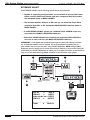
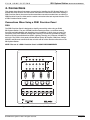
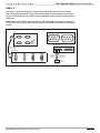
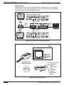
SS1 Rear Panel
2
1
3
NO
COM
NC
GND
PWR
NO
COM
NC
GND
PWR
NO
COM
NC
GND
PWR
NO
COM
NC
GND
PWR
NO
COM
NC
GND
PWR
NO
COM
NC
GND
PWR
NO
COM
NC
GND
PWR
NO
COM
NC
GND
PWR
GND
PWR
®
LEXINGTON, KY • MADE IN CHINA
MODEL: SS1 SYSTEM STATION
DC RELAY PWR
HOST RS-232
RELAY 1
RELAY 2
RELAY 4
RELAY 3
RELAY 5
COM 2
COM 1
COM1
COM2
COM3
ALL IR OUTPUT
1
2
IR OUTPUTS
4
3
5
6
SS1
POWER
12VDC
0.5 AMPS
+
-
VIA-NET
DOWNLOAD
LINK
RX/TX
4
COM 4
COM 3
ELAN RS-232
3
IR-LINK
ETHERNET
COM4
2
WARNING: DO NOT REMOVE COVER.
NO USER SERVICEABLE PARTS INSIDE.
REFER SERVICE TO ELAN-APPROVED
SERVICE TECHNICIAN.
RELAY 8
RELAY 7
SENSE INPUTS
1
HOST
ELAN
RELAY 6
5
6
EXT IR INPUT
7
8
9
10
11
IR
PWR
12
ENABLE
18 17 16
15
14
13
12 11
10
9
8
7
6
4
5
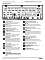
Figure 1.1 - SS1 Rear Panel
1
DC Relay Power
2
Relay 1-8
3
Power/IR Activity LEDs
4
12VDC Power Port
5
VIA!NET Port
6
7
8
9
Connect a 1-30V AC or DC power supply
for relay applications requiring power.
10
Download Enable Button
11
IR Link
12
Ethernet Activity LEDs
13
Ethernet Port
14
COM Port Activity LEDs
15
COM Ports 1-4
16
COM Port Activity LEDs
17
Host RS-232 Port
Connect a Normally Open (NO) or Normally
Closed (NC) Relay.
Indicates power status and IR activity.
Connect the included 12VDC power supply.
Provides a link to VIA! NET devices such
as the VIA!SC4. or additional SS1. Uses
ELAN Standard RJ-45 pinout.
IR Outputs
Connect up to 12 single or dual IR emitters
such as ELAN IRE1, IRE1D, IRE2, IRE2D, or
IRE4 IR Emitters. These outputs are programmable using VIA!TOOLS setup software.
EXT IR Input
Add a non-system IR receiver or keypad
for additional control options.
ALL IR Output
The sum of Outputs 1-12 is sent out the ALL
port. Connect IR emitters or IR distribution
blocks such as the ELAN IRD4 Amplified
Connection Block.
18
Press to enable VIA!TOOLS download.
DB-15 cable connects to ELAN Multi-Room
Controllers or additional SS1 System Stations.
Indicates Ethernet Link and Receive/Transmit
status.
Connect a Cat-5 cable with TIA568A Standard
RJ-45 terminator. Allows interaction with networked devices such as the VIA!2-8.4 Wireless
Touch Panel.
Indicates COM port activity status.
Connect RS-232 controlled devices such as
Lighting, Security, and HVAC from VIP Partners.
Indicates COM port activity status.
Used to download from VIA!TOOLS when is
SYSTEM mode.
ELAN RS-232 Port
Connect to ELAN 1-way RS-232 devices.
Sense Inputs
Connect ELANSENSE Sensors to create Triggers for automated events. Use VIA!TOOLS to
program sequences that control RS-232 or IR
devices.
© ELAN Home Systems 2007 • All rights reserved.
Page 7
SS1 System Station
ELAN
INSTALLATION MANUAL
HOME
SYSTEMS
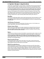
2. System Design & Applications
The first step to a good design is to map the system. It is advisable to mark up a copy of the house
floor plan with speaker, keypad, touch panel, touchpad, volume control, and equipment locations,
etc. Make sure that all locations are decided upon before pre-wiring commences so that all necessary wiring and installation hardware is in place. This unit will be interfacing with other components
such as relay-controlled devices, source components, sensors, serial controllers, and user interfaces, so it is essential that ALL system components are accounted for prior to the pre-wire stage.
Secondly, make a detailed list of all components. Include source equipment, touch panels, touchpads, keypads, RS-232 controlled devices, relay controlled devices, power supplies, sensors, and
the SS1 System Station itself. Be sure to include necessary electrical boxes, structured wiring
enclosures, telephone lines, rough-in brackets, ELAN Precision Panels, patch cables, etc.
Pre-Wire
Pre-wiring for the SS1 System Station requires careful system planning. Pay close attention to where
each component will be located and ensure that the appropriate wires are run to the correct locations! Make sure to plan for the future. It is often advantageous to pre-wire for components that may
be installed later.
VIA!2 Wireless Touchpanels
The VIA!2-8.4 Wireless Touch Panel's Base Station will require access to 110 VAC. Make sure to
locate the Base Station within range of a Wireless Access Point.
Wireless Access Points
Wireless Access Points (WAPs) take information originating from wireless VIA! Touch Panels and
send it to the system’s router. Keep in mind that local conditions and different WAP ranges will
make each installtion different. Test the range before finalizing the installation locations of WAPs.
Use Cat-5 cable to connect the WAP to the router.
Router
A Router (wired or wireless) is the heart of the VIA!28.4's communication system. Location of a wired
router is not critical, as long as access is provided for connections and service. A wireless router
must be located where it’s signal can reach the WAP and other wireless devices on the network. A
router will typically share duties between the wireless touch panels, VIA!dj Digital Music Servers,
VIA!dvdj DVD Controllers, and any computers in the customer’s home. Use Cat-5 cable to connect
the Router to the SS1 System Station.
Relay Controlled Devices
The SS1 System Station’s eight closed-contact relays can be used to control devices such as
lifts, projection screens, and drapes. Use two-conductor stranded cable between the SS1 System
Station’s RELAY terminals and the devices to be controlled.
RS-232 Controlled Devices
RS-232 communication is accomplished by loading drivers directly into the SS1 System Station
from VIA!TOOLS Setup Software. Connect serial cables or Cat-5 (w/ DB-9 connectors) between the
COM1-4 ports on the SS1 and the RS-232 device’s COM ports. COM1 and COM2 have Transmit/
Receive reversed compared to COM3 and COM4. Make sure to use the correct ports for the correct
RS-232 controlled devices! VIA!TOOLS setup software will help to determine which device should be
assigned to a particular COM port.
Page 8
© ELAN Home Systems 2007 • All rights reserved.
ELAN
HOME
SYSTEMS
SS1 System Station
INSTALLATION MANUAL
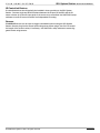
IR Controlled Devices
IR controlled devices should typically be installed in close proximity to the SS1 System
Station. Connect single and dual IR emitters between the IR ports of the SS1 and the IR
sensor window (or 3.5mm IR input jack) of the source to be controlled. Use VIA!TOOLS setup
software to create IR control functions and independent IR routing.
Sensors
ELANSENSE sensors can be used to trigger automated functions using the SS1 System
Station. Sensors plug into the Sense Inputs using stereo 3.5mm plugs. Use Cat-5 to extend
the length of the sensor’s wires, if necessary. Use VIA!TOOLs setup software to create triggered events using sensors.
© ELAN Home Systems 2007 • All rights reserved.
Page 9
SS1 System Station
ELAN
INSTALLATION MANUAL
HOME
SYSTEMS
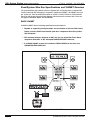
Zone/System Wire Run Specifications and VIA!NET Overview
The communication link between a Zone or System SS1 and all the wired or wireless VIA!
Touch Panels and Olé Touchpads in a system is called the ‘VIA!NET’. All VIA!NET wire runs
are “home-run” from each VIA!/Olé location to a PVIA 1, PVIA4, PVIA10 or PS12 Precision
Panel (as well as any future Precision Panels), which serve as the network hub. There are
two types of VIA!NETs: BASIC and EXTENDED.
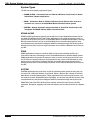
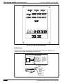
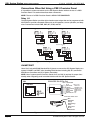
BASIC VIA!NET
A BASIC VIA!NET has the following specifications and limitations:
• Capable of supporting one System SS1 and a maximum of 30 wired VIA! Touch
Panels, wireless VIA!2 Touch Panels (with their companion Zone SS1s) and/or
Olé Touchpads.
• The maximum distance between an SS1 and any one wired VIA! Touch Panel
companion Zone SS1 or Olé Touchpad CANNOT EXCEED 1000 feet.
• In a BASIC VIA!NET system, the combined TOTAL LENGTH of the wire runs
CANNOT EXCEED 2000 feet.
NO
COM
NC
GND
NO
COM
NC
PWR
GND
PWR
NO
COM
NC
NO
COM
GND
PWR
NC
GND
PWR
NO
COM
NC
GND
PWR
NO
COM
NC
GND
PWR
NO
COM
NC
GND
NO
COM
NC
PWR
GND
PWR
GND
PWR
SS1
LEXINGTON, KY • MADE IN CHINA
MODEL: SS1 SYSTEM STATION
RELAY 1
DC RELAY PWR
RELAY 2
HOST RS-232
COM 1
COM 2
ELAN RS-232
COM 3
COM 4
HOST
ELAN
RELAY 3
RELAY 4
RELAY 5
RELAY 6
RELAY 7
SENSE INPUTS
COM 1
RELAY 8
WARNING: DO NOT REMOVE COVER.
NO USER SERVICEABLE PARTS INSIDE.
REFER SERVICE TO ELAN-APPROVED
SERVICE TECHNICIAN.
1
2
3
ALL IR OUTPUT
1
3
IR OUTPUTS
7
5
9
11
4
5
6
EXT IR INPUT
2
4
6
10
12
SS1
POWER
16VDC
+
-
IR-LINK
ETHERNET
COM 2
COM 3
COM 4
LINK
RX/TX
8
VIA-NET
PWR
IR
®
®
TO SENSE INPUTS
1
USE STEREO 3.5mm PLUGS ONLY
3
5
6
4
2
EXT IR
ANTENNA
XM
FM
ZONE
LOCAL
ZONE
LOCAL
ZONE
LOCAL
1
1
2
2
3
3
ZONE
LOCAL
ZONE
LOCAL
ZONE
LOCAL
4
4
5
5
6
6
ZONE
LOCAL
7
7
VIA!POWER
+
--
ZONE
LOCAL
8
8
16VDC / 10A
®
®
16VDC / 4A
VIA!NET
PS12, PVIA1,
PVIA4, PVIA10
NO
COM
NO
COM
NC
GND
PWR
NC
GND
PWR
NO
COM
NC
GND
NO
COM
NC
PWR
GND
PWR
NO
COM
NC
GND
PWR
NO
COM
NC
GND
NO
COM
NC
PWR
GND
PWR
NO
COM
NC
GND
PWR
GND
PWR
SS1
LEXINGTON, KY • MADE IN CHINA
MODEL: SS1 SYSTEM STATION
RELAY 1
DC RELAY PWR
HOST RS-232
COM 1
COM 3
ELAN RS-232
HOST
ELAN
RELAY 2
RELAY 3
RELAY 4
RELAY 5
COM 2
COM 4
RELAY 6
RELAY 7
SENSE INPUTS
COM 1
COM 2
RELAY 8
WARNING: DO NOT REMOVE COVER.
NO USER SERVICEABLE PARTS INSIDE.
REFER SERVICE TO ELAN-APPROVED
SERVICE TECHNICIAN.
1
2
3
ALL IR OUTPUT
1
3
IR OUTPUTS
7
5
9
11
4
5
6
EXT IR INPUT
2
4
6
10
12
SS1
POWER
16VDC
+
-
IR-LINK
ETHERNET
COM 3
LINK
COM 4
RX/TX
Wireless
Access
Point
8
VIA-NET
PWR
IR
®
Router
Wireless
Touch Panel
Figure 2.1 - Basic VIA!NET
Page 10
© ELAN Home Systems 2007 • All rights reserved.
SS1 System Station
SYSTEMS
1
NO
NO
COM
COM
NC
GND
NC
GND
PWR
PWR
NO
NO
COM
NC
COM
NC
GND
PWR
GND
PWR
NO
GND
PWR
NO
COM
NC
GND
PWR
NO
COM
NO
COM
NC
GND
NC
GND
PWR
PWR
GND
PWR
INSTALLATION MANUAL
2
SS1
COM
HOME
NC
ELAN
LEXINGTON, KY • MADE IN CHINA
MODEL: SS1 SYSTEM STATION
RELAY 1
DC RELAY PWR
HOST RS-232
RELAY 2
COM 1
COM 2
COM 3
COM 4
HOST
ELAN
RELAY 4
RELAY 5
RELAY 6
RELAY 7
SENSE INPUTS
COM 1
ELAN RS-232
RELAY 3
RELAY 8
WARNING: DO NOT REMOVE COVER.
NO USER SERVICEABLE PARTS INSIDE.
REFER SERVICE TO ELAN-APPROVED
SERVICE TECHNICIAN.
1
2
3
ALL IR OUTPUT
1
3
IR OUTPUTS
7
5
9
11
4
5
6
EXT IR INPUT
2
4
6
10
12
SS1
POWER
16VDC
+
-
IR-LINK
ETHERNET
COM 2
COM 3
COM 4
8
LINK
RX/TX
VIA-NET
PWR
IR
®
VIA!NET
NO
NO
COM
NC
COM
NC
GND
PWR
GND
NO
PWR
SS1
500 ft
COM
16VDC / 4A
1000 ft (Max)
NO
®
COM
8
NC
LOCAL
8
NC
ZONE
GND
--
16VDC / 10A
PWR
VIA!POWER
+
GND
7
PWR
LOCAL
7
NO
ZONE
COM
6
NC
LOCAL
6
GND
ZONE
5
PWR
LOCAL
5
NO
ZONE
4
NO
LOCAL
4
COM
ZONE
3
COM
3
NC
LOCAL
3
GND
ZONE
2
NC
LOCAL
2
GND
ZONE
1
PWR
LOCAL
1
PWR
ZONE
250 ft
NO
FM
COM
ANTENNA
XM
NC
EXT IR
GND
USE STEREO 3.5mm PLUGS ONLY
3
5
6
4
2
PWR
1
GND
TO SENSE INPUTS
PWR
250 ft
LEXINGTON, KY • MADE IN CHINA
MODEL: SS1 SYSTEM STATION
RELAY 1
DC RELAY PWR
RELAY 2
HOST RS-232
COM 1
COM 2
ELAN RS-232
COM 3
COM 4
HOST
ELAN
RELAY 3
RELAY 4
RELAY 5
RELAY 6
RELAY 7
SENSE INPUTS
COM 1
COM 2
COM 3
COM 4
RELAY 8
WARNING: DO NOT REMOVE COVER.
NO USER SERVICEABLE PARTS INSIDE.
REFER SERVICE TO ELAN-APPROVED
SERVICE TECHNICIAN.
1
2
3
ALL IR OUTPUT
1
3
IR OUTPUTS
7
5
9
11
4
5
6
EXT IR INPUT
2
4
6
10
12
SS1
POWER
16VDC
+
-
IR-LINK
ETHERNET
8
VIA-NET
LINK
RX/TX
PWR
IR
PS12, PVIA1,
PVIA4, PVIA10
Wireless
Access
Point
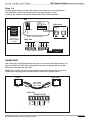
4
Olé #1
VIA! #2
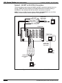
250 ft
500 ft
VIA!2-8.4/SS1 #3 = 250 ft
VIA! #4
=
1000 ft
_________________
Total
=
2000 ft
Router
=
=
Wireless
Touch Panel
Figure 2.2 - BASIC VIA!NET Wire Run Lengths
© ELAN Home Systems 2007 • All rights reserved.
Page 11
SS1 System Station
ELAN
INSTALLATION MANUAL
HOME
SYSTEMS
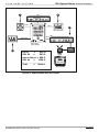
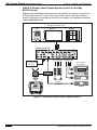
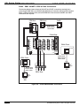
EXTENDED VIA!NET
An EXTENDED VIA!NET has the following specifications and limitations:
• Capable of supporting one System SS1 and a maximum of 30 wired VIA! Touch
Panels, wireless VIA!2 Touch Panels (with their companion Zone SS1s) and/or
Olé Touchpads (same as BASIC VIA!NET).
• The maximum distance between an SS1 and any one wired VIA! Touch Panel
companion Zone SS1 or Olé Touchpad CANNOT EXCEED 1000 feet (same as
BASIC VIA!NET).
• In an EXTENDED VIA!NET system, the combined TOTAL LENGTH of the wire
runs within the VIA!NET CAN EXCEED 2000 feet.
• Even when VIA!NET Repeaters are utilized, the combined TOTAL LENGTH of
wire runs in each “sub-net” still MUST NOT EXCEED 1000 feet.
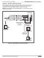
IMPORTANT! - If the 2000ft total combined wire length (to all the VIA! Panels) is exceeded, an Extended VIA!NET must be created. This is accomplished by breaking the longest VIA!NET wire runs into “sub-nets” using VIA!NET Repeaters. NOTE: Using VIA!NET
Repeaters does not enable you to extend the maximum distance to any one VIA! Panel (still
1000ft MAX), but VIA!NET Repeaters do enable you to increase the number of VIA! Panels on
long runs of wire while ensuring reliable operation of all VIA! Panels in the system.
NO
COM
NC
2
NO
COM
NC
GND
PWR
GND
PWR
NO
NO
COM
NC
GND
COM
NC
PWR
GND
PWR
NO
COM
NC
GND
PWR
NO
COM
NC
GND
PWR
LEXINGTON, KY • MADE IN CHINA
MODEL: SS1 SYSTEM STATION
RELAY 2
RELAY 3
RELAY 4
RELAY 5
COM 2
RELAY 6
2
3
RELAY 8
IR OUTPUTS
7
5
WARNING: DO NOT REMOVE COVER.
NO USER SERVICEABLE PARTS INSIDE.
REFER SERVICE TO ELAN-APPROVED
SERVICE TECHNICIAN.
9
11
SS1
POWER
16VDC
+
-
IR-LINK
ETHERNET
5
4
COM 2
COM 3
COM 4
6
4
2
EXT IR INPUT
6
8
10
12
VIA-NET
LINK
RX/TX
PWR
IR
FM
NO
COM
NO
COM
NC
GND
PWR
NC
GND
NO
PWR
SS1
16VDC / 4A
1000 ft (Max)
COM
8
PWR
®
NC
LOCAL
8
NO
ZONE
COM
--
16VDC / 10A
GND
VIA!POWER
+
PWR
7
NC
LOCAL
7
GND
ZONE
PWR
6
NO
LOCAL
6
COM
ZONE
5
NC
LOCAL
5
GND
ZONE
4
PWR
LOCAL
4
NO
ZONE
3
COM
3
NC
LOCAL
3
NO
ZONE
2
COM
LOCAL
2
®
500 ft
ANTENNA
XM
ZONE
1
NC
EXT IR
LOCAL
GND
USE STEREO 3.5mm PLUGS ONLY
3
5
6
4
2
1
PWR
1
ZONE
GND
TO SENSE INPUTS
PWR
500 ft
1
NO
COM 4
ALL IR OUTPUT
COM
HOST
ELAN
3
NC
COM 1
COM 3
ELAN RS-232
RELAY 7
SENSE INPUTS
1
GND
COM 1
GND
RELAY 1
DC RELAY PWR
HOST RS-232
PWR
NO
COM
NO
COM
NC
GND
PWR
NC
GND
GND
PWR
PWR
SS1
1
LEXINGTON, KY • MADE IN CHINA
VIA!NET
MODEL: SS1 SYSTEM STATION
RELAY 1
DC RELAY PWR
HOST RS-232
800 ft
PS12, PVIA1,
VIA!NET PVIA4, PVIA10
Repeater
COM 1
COM 3
ELAN RS-232
HOST
ELAN
RELAY 2
RELAY 3
RELAY 4
RELAY 5
COM 2
COM 4
RELAY 6
COM 1
COM 2
COM 3
COM 4
WARNING: DO NOT REMOVE COVER.
NO USER SERVICEABLE PARTS INSIDE.
REFER SERVICE TO ELAN-APPROVED
SERVICE TECHNICIAN.
3
ALL IR OUTPUT
1
3
IR OUTPUTS
7
5
9
11
ETHERNET
4
5
6
EXT IR INPUT
2
4
6
10
12
8
SS1
POWER
16VDC
+
-
VIA-NET
LINK
RX/TX
Wireless
Access
Point
=
=
RELAY 8
2
PWR
IR
VIA!NET
Repeater
4
Olé #1
VIA! #2
RELAY 7
SENSE INPUTS
1
IR-LINK
500 ft
800 ft
VIA!2-8.4/SS1 #3 = 500 ft
VIA! #4
=
1000 ft
_________________
Total
=
2800 ft
Router
Wireless
Touch Panel
Figure 2.3 - EXTENDED VIA!NET Wire Run Length
Page 12
© ELAN Home Systems 2007 • All rights reserved.
ELAN
HOME
SS1 System Station
SYSTEMS
INSTALLATION MANUAL
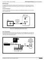
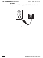
VIA!NET Repeaters
VIA!NET Reaters allow devices to be installed at distances that are in excess of normal maximum wire run lengths. Punch the repeater down on a PVIA or other VIA!NET Precision Panel
as shown in the drawing below.
Keep in mind the following points:
•
Use VIA!NET Repeaters when the TOTAL combined wire length to all VIA!
Touch Panels exceeds the 2000 ft. maximum limit.
NOTE: Wire runs WITH VIA!NET Repeaters still must not exceed 1000ft. in length.
•
As many as 30 wire runs WITH VIA!NET Repeaters may be utilized, as long as
NONE of the individual runs exceed 1000 ft. in length.
•
The combined length of all wire runs remaining WITHOUT VIA!NET Repeaters
(‘sub-net’) must not exceed 1000 ft.
ELAN Precision Panel
Zone Connector
N/C
W/Bl
Or
W/Or
Gr
W/Gr
Br
W/Br
Blue (N/C)
White/Blue
Orange
White/Orange
Green
White/Green
Brown
White/Brown
Butt splice
or equivalent
VIA!Net Repeater
Blue
White/Blue
Orange
White/Orange
Green
White/Green
Brown
White/Brown
Blue (N/C)
White/Blue (IR)
Orange (485-)
White/Orange (485+)
Green (GND)
White/Green (+16V)
Brown (GND)
White/Brown (+16V)
VIA!
or
Olé
ELAN
C45P
Figure 2.4 - VIA!NET Repeaters
SS1
Blue (Pin 1) - System Sense In
White/Blue (Pin 2) - System IR Out
Orange (Pin 3) - VIA!Net RS-485 White/Orange (Pin 4) - VIA!Net RS-485 +
Green (Pin 5) - ZNet 485 White/Green (Pin 6) - ZNet 485 +
Brown (Pin 7) - N/C
White/Brown (Pin 8) - N/C
VIA!NET
87654321
Figure 2.5 - VIA!NET Pinout
© ELAN Home Systems 2007 • All rights reserved.
Page 13
SS1 System Station
INSTALLATION MANUAL
ELAN
HOME
SYSTEMS
System Types
The SS1 has three primary application Types:
• STAND-ALONE - Connection Hub for VIA!2-8.4 Wireless Touch Panels in StandAlone/Home Theater applications
• ZONE - Connection Hub for VIA!2-8.4 Wireless Touch Panels when used as a
controller for a zone in an ELAN Multi-Room Controller-based system
• SYSTEM - System Controller when connected to wired VIA! Touch Panels, Olé
Touchpads and ZONE VIA!2-8.4/SS1 Connection Hubs
STAND-ALONE
STAND-ALONE applications typically use the SS1 as a Control Station/Connection Hub for
the VIA!2-SS1 Wireless Touch Panel. These applications can provide IR routing in order to
control local IR sources (not part of an ELAN Multi-Room Controller-based system), one-way
RS-232 devices that are not part of an ELAN Multi-Room Controller-based system, relay
controlled devices, and perform intelligent ON/OFF commands through the Sense Inputs. A
Wireless Access Point is used to relay information from a VIA!2-8.4 Wireless Touch Panel to
the SS1.
ZONE
ZONE applications consist of a wireless VIA!2-8.4 Touch Panel utilizing the SS1 as a
Connection Hub when controlling a zone of an ELAN Multi-Room Controller-based system.
ZONE applications can provide IR routing in order to control local IR sources, IR zone control, IR control of system-wide sources, one and two-way control of RS-232 devices, relay
device control, and perform intelligent ON/OFF commands through the Sense Inputs. A
Wireless Access Point is used to relay information from a VIA!2-8.4 Wireless Touch Panel to
the SS1.
SYSTEM
SYSTEM applications are used when an SS1 is performing tasks outside of being the control center for a VIA!2-8.4 Wireless Touch Panel. Often, a System SS1 is linked to an ELAN
Multi-Room Controller-based system. These applications can control local IR sources, system-wide IR sources, ELAN Multi-Room Controllers, one and two-way RS-232 devices, relay
controlled devices, and perform intelligent ON/OFF commands through the Sense Inputs.
ZONE SS1s (with VIA!2-SS1 Wireless Touch Panels), wired VIA! Touch Panels, Olé Film
Interactive Touchpads, keypads, and hand-held remotes can all utilize functions of a System
SS1.
Page 14
© ELAN Home Systems 2007 • All rights reserved.
ELAN
HOME
SS1 System Station
SYSTEMS
INSTALLATION MANUAL
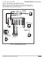
STAND-ALONE Applications
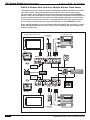
VIA!2-8.4 Wireless Home Theater System Control
The SS1 System Station makes an excellent STAND-ALONE Home Theater Controller.
Figure 2.6 shows a STAND-ALONE SS1 System Station providing IR A/V source control,
relay control of lifts, screens, and drapes, Ethernet control of a VIA!dvdj, and automated
functionality using ELANSENSE Sensors.
Relay Controlled Devices (x8)
Screen
Lift
Drapes
Relay
STAND-ALONE SS1
NO
COM
NC
GND
NO
PWR
COM
NC
GND
NO
PWR
COM
NC
GND
NO
PWR
COM
NC
GND
PWR
NO
COM
NC
GND
PWR
NO
COM
NC
GND
NO
PWR
COM
NC
GND
NO
COM
PWR
NC
GND
PWR
GND
PWR
®
LEXINGTON, KY • MADE IN CHINA
MODEL: SS1 SYSTEM STATION
DC RELAY PWR
HOST RS-232
RELAY 1
COM 1
RELAY 2
RELAY 3
RELAY 4
RELAY 5
COM 2
COM1
2
COM3
COM4
ELAN RS-232
COM 3
ALL IR OUTPUT
3
RELAY 8
RELAY 7
1
2
IR OUTPUTS
4
3
5
6
SS1
POWER
12VDC
0.5 AMPS
+
-
IR-LINK
ETHERNET
COM2
HOST
ELAN
RELAY 6
SENSE INPUTS
1
WARNING: DO NOT REMOVE COVER.
NO USER SERVICEABLE PARTS INSIDE.
REFER SERVICE TO ELAN-APPROVED
SERVICE TECHNICIAN.
LINK
RX/TX
VIA-NET
DOWNLOAD
5
4
COM 4
6
EXT IR INPUT
7
8
9
10
11
12
ENABLE
Sense Inputs (x6)
IR
PWR
IR Outputs (x12)
Home Theater
Components
AUDIO SENSOR
CONTACT SENSOR
Wireless
Touch Panel
Router
LED/LIGHT SENSOR
Wireless
Access
Point
ELAN SENSE
Sensors
IR Emitter
IR Emitter
IR Emitter
ETHERNET
VIA!dvdj
Figure 2.6 - Stand-Alone Home Theater
© ELAN Home Systems 2007 • All rights reserved.
Page 15
SS1 System Station
ELAN
INSTALLATION MANUAL
HOME
SYSTEMS
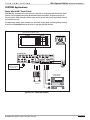
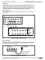
VIA!2-8.4 Wireless Home Theater System Control w/ One-Way
RS-232 Control
Figure 2.7 shows a STAND-ALONE application using the SS1 as a wireless connection hub
and providing IR A/V source control, relay control of lifts, screens, and drapes, Ethernet
control of a VIA!dvdj, one-way RS-232 control of local systems, and automated functionality
using ELANSENSE Sensors.
Relay Controlled Devices (x8)
Screen
Lift
Drapes
Relay
STAND-ALONE SS1
NO
COM
NC
NO
GND
COM
PWR
NC
NO
GND
PWR
COM
NC
NO
GND
PWR
COM
NC
GND
PWR
NO
COM
NC
GND
PWR
NO
COM
NC
GND
NO
COM
PWR
NC
NO
GND
COM
PWR
NC
GND
PWR
GND
PWR
®
LEXINGTON, KY • MADE IN CHINA
MODEL: SS1 SYSTEM STATION
DC RELAY PWR
HOST RS-232
RELAY 1
COM 1
RELAY 2
COM3
COM4
COM 3
RELAY 4
RELAY 5
RELAY 6
WARNING: DO NOT REMOVE COVER.
NO USER SERVICEABLE PARTS INSIDE.
REFER SERVICE TO ELAN-APPROVED
SERVICE TECHNICIAN.
RELAY 8
RELAY 7
SENSE INPUTS
COM1
COM2
HOST
ELAN
ELAN RS-232
RELAY 3
COM 2
1
2
3
ALL IR OUTPUT
1
2
IR OUTPUTS
4
3
5
6
4
5
6
EXT IR INPUT
7
8
9
11
12
VIA-NET
DOWNLOAD
LINK
RX/TX
10
ENABLE
Sense Inputs (x6)
One -Way
RS-232 Controlled
Devices (x4)
Home Theater
Components
AUDIO SENSOR
CONTACT SENSOR
LED/LIGHT SENSOR
Router
IR Emitter
IR Emitter
ELAN® SENSE
Sensors
ETHERNET
Wireless
Touch Panel
IR
PWR
IR Outputs (x12)
RS-232
Wireless
Access
Point
SS1
POWER
12VDC
0.5 AMPS
+
-
IR-LINK
ETHERNET
COM 4
IR Emitter
VIA!dvdj
Figure 2.7 - Stand-Alone Home Theater w/ RS-232 Control
Page 16
© ELAN Home Systems 2007 • All rights reserved.
ELAN
HOME
SS1 System Station
SYSTEMS
INSTALLATION MANUAL
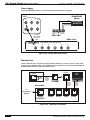
ZONE Applications
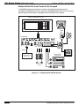
VIA!2-8.4 Wireless Zone Control
Zone applications utilize the SS1 as a control hub for a wireless VIA!2-8.4 Touch Panel
(ZONE application) used as a controller for a zone of an ELAN Multi-Room Controller. Oneway RS-232 control is available for devices that are only controlled from the zone in which
the VIA!2-8.4 Touch Panel is assigned (local Home Theater equipment, for example). Relay
and Sense functions are available for local systems, as well as IR control of local (in-zone)
and system (available from any zone) devices. Be aware that two-way and system-wide RS232 control is NOT available in this application.
Relay Controlled Devices (x8)
Screen
Lift
Zone 3
Zone 2
Drapes
Cat-5
Cat-5
Olé
2
1
1
Relay
PVIA-4
Zone 1
Home Theater
ZONE SS1
NO
COM
NC
NO
GND
COM
PWR
NC
GND
NO
COM
PWR
NC
NO
GND
COM
NC
PWR
GND
PWR
NO
COM
NC
GND
PWR
NO
COM
NC
NO
GND
COM
PWR
NC
GND
NO
COM
PWR
NC
GND
PWR
GND
PWR
®
LEXINGTON, KY • MADE IN CHINA
MODEL: SS1 SYSTEM STATION
DC RELAY PWR
HOST RS-232
RELAY 1
COM 1
RELAY 2
RELAY 3
RELAY 4
RELAY 5
COM 2
COM2
COM3
2
HOST
ELAN
COM4
COM 3
ALL IR OUTPUT
3
1
2
WARNING: DO NOT REMOVE COVER.
NO USER SERVICEABLE PARTS INSIDE.
REFER SERVICE TO ELAN-APPROVED
SERVICE TECHNICIAN.
RELAY 8
RELAY 7
SENSE INPUTS
1
COM1
ELAN RS-232
RELAY 6
IR OUTPUTS
4
3
5
LINK
RX/TX
5
4
6
EXT IR INPUT
7
8
9
10
11
12
ENABLE
Sense Inputs (x6)
1-Way
RS-232 Controlled
Devices (x4)
SS1
POWER
12VDC
0.5 AMPS
+
-
VIA-NET
DOWNLOAD
COM 4
IR
PWR
SYS
SENSE
4
Cat-5
TO SC-4
VIDEO
IN
1
3
2
4
Zone 4
PVIA4
Cat-5
Cat-5
ELAN Multi-Room
Controller
Home Theater
Components
AUDIO SENSOR
CONTACT SENSOR
LED/LIGHT SENSOR
Router
IR Emitter
IR
IR Emitter
ELANSENSE
Sensors
Wireless
Touch Panel
3
4
IR Outputs (x12)
RS-232
Wireless
Access
Point
+16VDC
POWER
IR
OUT
ALL
6
IR-LINK
ETHERNET
3
2
9 VDC
SENSE
INPUTS
IR Emitter
ETHERNET
VIA!dvdj
Zone 1
Home Theater
Figure 2.8 - Wireless Zone Control
© ELAN Home Systems 2007 • All rights reserved.
Page 17
SS1 System Station
ELAN
INSTALLATION MANUAL
HOME
SYSTEMS
VIA!2-8.4 Wireless Zone Control w/ Multiple Wireless Touch Panels
This application uses two VIA!2-8.4 Wireless Touch panels as ZONE controllers for an ELAN
multi-room system. These wireless panels provide IR A/V source control, relay control,
one-way control of local RS-232 devices, and automated functionality using ELANSENSE
Sensors in their own zones (Zones 1 and 2). All zone functions and whole-house sources can
also be controlled from these touch panels. An Olé Touchpad is assigned to control Zone 3
and a VIA!64 Touch Panel controls Zone 4. These VIA! and Olé can control system IR sources, but not the local IR components, relay controlled devices, or ELANSENSE functions.
Notice that this application uses one Wireless Access Point (WAP) and one Router. In certain
cases, dedicated WAPs may need to be used in order to obtain proper signal strength and
wireless coverage area.
Relay Controlled Devices (x8)
Local IR Components
ELAN SENSE
Sensors
AUDIO SENSOR
CONTACT SENSOR
Screen
Zone 1
Relay
Olé
Wireless
Touch Panel
Sense
Inputs (x6)
ZONE SS1
IR Outputs
(x12)
NO
COM
NO
NC
COM
NC
GND
PWR
NO
COM
NC
GND
PWR
NO
COM
NC
GND
GND
PWR
PWR
NO
COM
NC
GND
PWR
NO
COM
NO
COM
NC
GND
PWR
NO
COM
NC
GND
PWR
GND
NC
GND
PWR
PWR
®
LEXINGTON, KY • MADE IN CHINA
MODEL: SS1 SYSTEM STATION
DC RELAY PWR
HOST RS-232
RELAY 1
RELAY 2
RELAY 5
COM 2
COM 1
WARNING: DO NOT REMOVE COVER.
NO USER SERVICEABLE PARTS INSIDE.
REFER SERVICE TO ELAN-APPROVED
SERVICE TECHNICIAN.
RELAY 8
RELAY 7
SENSE INPUTS
1
2
3
ALL IR OUTPUT
1
2
IR OUTPUTS
4
3
5
6
4
5
6
EXT IR INPUT
7
8
9
11
12
LINK
COM4
RX/TX
10
Zone 3
SS1
POWER
12VDC
0.5 AMPS
+
-
VIA-NET
DOWNLOAD
COM3
COM 4
COM 3
RELAY 6
IR-LINK
ETHERNET
COM1
COM2
HOST
ELAN
ELAN RS-232
RELAY 4
RELAY 3
IR
PWR
ENABLE
Zone 1
1-Way
RS-232 Controlled
Devices (x4)
Cat-5
RS-232
Cat-5
2
1
1
PVIA-4
Wireless
Access
Point
Router
1-Way
RS-232 Controlled
Devices (x4)
3
IR
OUT
3
2
9 VDC
SENSE
INPUTS
+16VDC
POWER
4
ALL
SYS
SENSE
4
Cat-5
TO SC-4
VIDEO
IN
1
3
4
PVIA4
Cat-5
RS-232
2
ELAN Multi-Room
Controller
Cat-5
Zone 2
NO
COM
NC
NO
COM
NC
GND
GND
PWR
NO
COM
NC
GND
PWR
PWR
NO
COM
NC
GND
PWR
NO
COM
NC
GND
PWR
NO
COM
NO
COM
NC
GND
PWR
NO
COM
NC
GND
PWR
NC
GND
GND
PWR
PWR
®
LEXINGTON, KY • MADE IN CHINA
MODEL: SS1 SYSTEM STATION
DC RELAY PWR
HOST RS-232
RELAY 1
RELAY 2
COM 1
COM 2
COM 3
COM 4
RELAY 4
RELAY 5
RELAY 6
WARNING: DO NOT REMOVE COVER.
NO USER SERVICEABLE PARTS INSIDE.
REFER SERVICE TO ELAN-APPROVED
SERVICE TECHNICIAN.
RELAY 8
RELAY 7
SENSE INPUTS
COM1
COM2
HOST
ELAN
ELAN RS-232
RELAY 3
1
2
3
ALL IR OUTPUT
1
2
IR OUTPUTS
4
3
5
6
4
5
6
EXT IR INPUT
7
8
9
11
12
LINK
COM4
RX/TX
VIA-NET
DOWNLOAD
10
ENABLE
Wireless
Touch Panel
ZONE SS1
SS1
POWER
12VDC
0.5 AMPS
+
-
IR-LINK
ETHERNET
COM3
IR Outputs
Sense
(x12)
Inputs (x6)
IR
PWR
Zone 4
Relay
Zone 2
AUDIO SENSOR
Relay Controlled Devices (x8)
CONTACT SENSOR
Screen
ELANSENSE
Sensors
Local IR Components
Figure 2.9 - Wireless Zone Control w/ Multiple Touch Panels/Olés
Page 18
© ELAN Home Systems 2007 • All rights reserved.
ELAN
HOME
SS1 System Station
SYSTEMS
INSTALLATION MANUAL
SYSTEM Applications
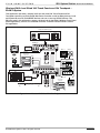
Basic Wired VIA! Touch Panel
SYSTEM SS1 applications involve the use of the SS1 in conjunction with wired VIA! Touch
panels, Olé Touchpads and (often) ELAN Multi-Room Controllers. IR system control, IR
source control, Relay functions, Sense Input functions and one or two-way RS-232 control
are possible, as well.
The application shown here consists of a wired VIA! Touch panel controlling Relay devices,
IR sources, ELANSENSE devices and one or two-way RS-232 devices.
Relay Controlled Devices (x8)
Screen
Drapes
Relay
SYSTEM SS1
NO
COM
NC
NO
GND
COM
PWR
NC
GND
NO
PWR
COM
NC
NO
GND
COM
PWR
NC
GND
PWR
NO
COM
NC
GND
PWR
NO
COM
NC
NO
GND
PWR
COM
NC
GND
NO
COM
PWR
NC
GND
PWR
GND
PWR
®
LEXINGTON, KY • MADE IN CHINA
MODEL: SS1 SYSTEM STATION
DC RELAY PWR
HOST RS-232
RELAY 1
COM 1
RELAY 2
RELAY 3
RELAY 4
RELAY 5
COM 2
COM1
COM2
COM3
COM4
HOST
ELAN
ELAN RS-232
COM 3
RELAY 6
2
3
ALL IR OUTPUT
RELAY 8
RELAY 7
SENSE INPUTS
1
1
2
WARNING: DO NOT REMOVE COVER.
NO USER SERVICEABLE PARTS INSIDE.
REFER SERVICE TO ELAN-APPROVED
SERVICE TECHNICIAN.
IR OUTPUTS
4
3
5
6
SS1
POWER
12VDC
0.5 AMPS
+
-
IR-LINK
ETHERNET
VIA-NET
DOWNLOAD
LINK
RX/TX
4
COM 4
5
6
EXT IR INPUT
7
8
9
10
11
12
ENABLE
IR
PWR
IR
9VDC PWR9
Sense Inputs (x6) IR Outputs (x12)
1 & 2-Way
RS-232 Controlled
Devices (x4)
Local Port
OUT
16VDC PWR1
TO VIA!VALET
VIDEO
IN
PVIA-1
Valet
RS-232
AUDIO SENSOR
CONTACT SENSOR
LED/LIGHT SENSOR
ELAN® SENSE
Sensors
Home Theater
Components
IR Emitter
IR Emitter
IR Emitter
Figure 2.10 - Wired VIA! System
© ELAN Home Systems 2007 • All rights reserved.
Page 19
SS1 System Station
ELAN
INSTALLATION MANUAL
HOME
SYSTEMS
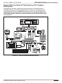
Multiple Wired VIA! Touch Panels & Olé Touchpad
The SYSTEM application shown here consists of wired VIA! Touch Panels and Olé
Touchpads controlling Relay devices, IR sources, ELANSENSE devices and one or two-way
RS-232 devices. Each function is available from all controllers in the system.
Relay Controlled Devices (x8)
Screen
Drapes
PVIA1
Valet
IR
Relay
Olé
OUT
9VDC PWR9
16VDC PWR1
TO VIA!VALET
SYSTEM SS1
VIDEO
IN
NO
COM
NC
GND
NO
PWR
COM
NC
GND
NO
PWR
COM
NC
GND
NO
PWR
COM
NC
GND
PWR
NO
COM
NC
GND
PWR
NO
COM
NC
GND
NO
COM
PWR
NC
NO
GND
COM
PWR
NC
GND
PWR
GND
PWR
®
LEXINGTON, KY • MADE IN CHINA
MODEL: SS1 SYSTEM STATION
DC RELAY PWR
HOST RS-232
RELAY 1
COM 1
RELAY 2
RELAY 5
RELAY 6
COM2
COM3
COM4
WARNING: DO NOT REMOVE COVER.
NO USER SERVICEABLE PARTS INSIDE.
REFER SERVICE TO ELAN-APPROVED
SERVICE TECHNICIAN.
RELAY 8
RELAY 7
SENSE INPUTS
COM1
COM 3
RELAY 4
COM 2
HOST
ELAN
ELAN RS-232
RELAY 3
1
2
3
ALL IR OUTPUT
1
2
IR OUTPUTS
4
3
4
5
6
EXT IR INPUT
7
8
9
5
6
11
12
SS1
POWER
12VDC
0.5 AMPS
+
-
IR-LINK
ETHERNET
VIA-NET
DOWNLOAD
LINK
RX/TX
COM 4
10
ENABLE
2
1
1
PVIA-4
IR
3
2
9 VDC
SENSE
INPUTS
+16VDC
POWER
3
PWR
IR
OUT
4
ALL
SYS
SENSE
4
TO SC-4
VIDEO
IN
1
2
3
4
Sense Inputs (x6) IR Outputs (x12)
PVIA4
RS-232
Home Theater
Components
AUDIO SENSOR
CONTACT SENSOR
LED/LIGHT SENSOR
1 & 2-Way
RS-232 Controlled
Devices (x4)
IR Emitter
ELAN® SENSE
Sensors
IR Emitter
IR Emitter
Figure 2.11 - Multiple Wired VIA!/Olé System
Page 20
© ELAN Home Systems 2007 • All rights reserved.
ELAN
HOME
SS1 System Station
SYSTEMS
INSTALLATION MANUAL
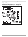
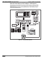
VIA!2-8.4 Wireless Touch Panel w/ Wired VIA! Touch Panels
and Olé Touchpads
This application uses a VIA!2-8.4 Wireless Touch panel in combination with wired VIA! Touch
Panels and Olé Touchpads controlling Relay devices, IR sources, ELANSENSE devices and
one or two-way RS-232 devices. There are two SS1s required for this application: one used
as a wireless hub for the VIA!2-8.4 (ZONE application) and one used as a SYSTEM controller.
Screen
Lift
Drapes
Relay Controlled Devices (x8)
Relay
NO
COM
NC
GND
PWR
NO
NO
COM
NC
GND
PWR
NO
COM
COM
NC
NC
GND
PWR
GND
PWR
NO
COM
NC
GND
PWR
NO
COM
NC
GND
PWR
NO
NO
COM
COM
NC
GND
NC
GND
PWR
PWR
GND
PWR
ZONE SS1
LEXINGTON, KY • MADE IN CHINA
MODEL: SS1 SYSTEM STATION
RELAY 1
DC RELAY PWR
RELAY 2
RELAY 3
RELAY 4
RELAY 5
RELAY 6
RELAY 7
RELAY 8
WARNING: DO NOT REMOVE COVER.
NO USER SERVICEABLE PARTS INSIDE.
REFER SERVICE TO ELAN-APPROVED
SERVICE TECHNICIAN.
Local One-Way
RS-232 Controlled
Devices (x4)
HOST RS-232
COM 2
COM 1
SENSE INPUTS
LINK
RX/TX
COM 4
COM 3
3
ALL IR OUTPUT
1
2
4
5
6
EXT IR INPUT
7
8
5
6
11
12
SS1
POWER
12VDC
0.5 AMPS
+
-
VIA-NET
COM3
COM4
HOST
ELAN
ELAN RS-232
2
IR-LINK
ETHERNET
COM1
COM2
IR OUTPUTS
4
3
1
10
IR
PWR
IR Outputs (x12)
Sense Inputs (x6)
RS-232
9
ETHERNET
Wireless
Touch Panel
Olé
AUDIO SENSOR
IR Emitter
IR Emitter
CONTACT SENSOR
LED/LIGHT SENSOR
Home Theater
Components
PVIA-10
IR Emitter
ELANSENSE
Sensors
VIA!NET
POWER
SYSTEM SS1
COM 3
COM 4
COM 2
COM 1
VIA!dvdj
SP
ARE
COM
PORTS
+
Router
RELA
Y 5/6
-
Wireless
Access
Point
RELA
Y CONTROLOUTPUTS
RELA
Y 3/4
RELA
Y 1/2
2
3
16 VDC 10A
ALL
IR OUTPUTS
1
4
5
A
9
10
B
SYS IR
7
8
2
3
SYS SNS
NO
COM
NC
GND
PWR
NO
NO
COM
NC
GND
PWR
COM
NC
GND
PWR
NO
COM
NC
GND
PWR
NO
COM
NC
GND
PWR
NO
COM
NC
GND
PWR
NO
COM
NC
GND
PWR
NO
COM
NC
GND
PWR
GND
PWR
VIA!NET
6
1
SM
ART SENSE INPUTS
Relay
LEXINGTON, KY • MADE IN CHINA
MODEL: SS1 SYSTEM STATION
RELAY 1
DC RELAY PWR
RELAY 2
RELAY 3
RELAY 4
RELAY 5
RELAY 6
RELAY 7
WARNING: DO NOT REMOVE COVER.
NO USER SERVICEABLE PARTS INSIDE.
REFER SERVICE TO ELAN-APPROVED
SERVICE TECHNICIAN.
HOST RS-232
COM 1
COM 2
COM 3
COM 4
SENSE INPUTS
COM1
COM2
COM3
COM4
HOST
ELAN
ELAN RS-232
ETHERNET
1
2
3
ALL IR OUTPUT
1
2
4
5
6
EXT IR INPUT
7
8
IR OUTPUTS
4
3
5
6
11
12
5
6
7
8
VIA-NET
9
10
VIDEO IN
SS1
POWER
12VDC
0.5 AMPS
+
-
IR-LINK
LINK
RX/TX
4
RELAY 8
IR
PWR
1
3
5
7
9
2
4
6
8
10
PVIA-10
Sense Inputs (x6) IR Outputs (x12)
1 & 2-Way
RS-232 Controlled
Devices (x4)
CONTACT SENSOR
IR Controlled
Components
AUDIO SENSOR
Garage Door
LED/LIGHT SENSOR
Gate
VIA!Net
RS-232
IR Emitter
ELANSENSE
Sensors
IR Emitter
IR Emitter
Relay Controlled Devices (x8)
Figure 2.12 - WirelessVIA!/Wired VIA!/Olé System
© ELAN Home Systems 2007 • All rights reserved.
Page 21
SS1 System Station
ELAN
INSTALLATION MANUAL
HOME
SYSTEMS
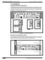
Wired VIA! Touch Panels and Olé Touchpads - ELAN Z•System
This application uses wired VIA! Touch Panels and Olé Touchpads controlling an ELAN
Z•630 Mult-Room Controller as well as Relay devices, local and system IR sources,
ELANSENSE devices and one or two-way RS-232 devices. A PVIA10 Precision Panel is
used in this SYSTEM application.
Relay Controlled Devices (x8)
Screen
Lift
Drapes
Olé
PVIA-10
Z•630
RELA
Y CONTROLOUTPUTS
RELA
Y 3/4
RELA
Y 1/2
RELA
Y 5/6
SP
ARE
COM 4
COM 3
+
POWER
-
COM 1
COM 2
COM
PORTS
16 VDC 10A
ALL
IR OUTPUTS
SYSTEM SS1
1
2
3
4
5
A
6
7
8
9
10
B
SYS IR
VIA!NET
SM
ART SENSE INPUTS
NO
COM
NC
NO
COM
GND
PWR
NC
NO
COM
GND
PWR
NC
NO
COM
GND
PWR
NC
GND
PWR
NO
COM
NC
GND
PWR
NO
COM
NC
NO
COM
GND
PWR
NC
NO
COM
GND
PWR
NC
GND
PWR
GND
PWR
SYS SNS
1
Relay
2
3
4
5
6
7
8
LEXINGTON, KY • MADE IN CHINA
MODEL: SS1 SYSTEM STATION
RELAY 1
DC RELAY PWR
RELAY 2
RELAY 3
RELAY 4
RELAY 5
RELAY 6
RELAY 7
RELAY 8
VIDEO IN
WARNING: DO NOT REMOVE COVER.
NO USER SERVICEABLE PARTS INSIDE.
REFER SERVICE TO ELAN-APPROVED
SERVICE TECHNICIAN.
HOST RS-232
COM 1
COM 2
SENSE INPUTS
1
COM1
COM2
COM3
HOST
ELAN
ELAN RS-232
COM4
COM 3
2
3
ALL IR OUTPUT
1
2
IR OUTPUTS
4
3
5
SS1
POWER
12VDC
0.5 AMPS
+
-
IR-LINK
ETHERNET
VIA-NET
LINK
RX/TX
4
COM 4
5
6
EXT IR INPUT
7
8
9
10
11
1
3
5
7
9
2
4
6
8
10
6
12
IR
PWR
PVIA-10
Sense Inputs (x6) IR Outputs (x12)
VIA!Net
CONTACT SENSOR
IR Controlled
Components
AUDIO SENSOR
RS-232
LED/LIGHT SENSOR
1 & 2-Way
RS-232 Controlled
Devices (x4)
IR Emitter
ELANSENSE
Sensors
IR Emitter
IR Emitter
Figure 2.13 - Wired VIA!/Olé Z•System
Page 22
© ELAN Home Systems 2007 • All rights reserved.
ELAN
HOME
SS1 System Station
SYSTEMS
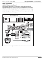
INSTALLATION MANUAL
Wireless VIA!8.4 and Wired VIA! Touch Panels and Olé Touchpads ELAN Z•System
This application uses both a wireless VIA!2-8.4 and wired VIA! Touch Panels and Olé
Touchpads controlling an ELAN Z•630 Mult-Room Controller as well as Relay devices, Local
and System IR sources, ELANSENSE devices and one or two-way RS-232 devices. Two
SS1s are used in this application: one as a wireless hub for the VIA!8.4 Wireless Touch Panel
(ZONE application), and one as a SYSTEM controller. A PVIA10 Precision Panel is used in
this application.
Relay Controlled Devices (x8)
Screen
Lift
Drapes
Relay
NO
COM
NC
GND
PWR
NO
NO
COM
NC
GND
PWR
NO
COM
NC
COM
NC
GND
GND
PWR
PWR
NO
COM
NC
GND
PWR
NO
NO
COM
NC
GND
PWR
NO
COM
COM
NC
NC
GND
GND
PWR
GND
PWR
Zone 1
PWR
ZONE SS1
LEXINGTON, KY • MADE IN CHINA
MODEL: SS1 SYSTEM STATION
RELAY 1
DC RELAY PWR
Wireless
Touch Panel
RELAY 2
RELAY 3
RELAY 4
RELAY 5
RELAY 6
RELAY 7
RELAY 8
WARNING: DO NOT REMOVE COVER.
NO USER SERVICEABLE PARTS INSIDE.
REFER SERVICE TO ELAN-APPROVED
SERVICE TECHNICIAN.
Local One-Way
RS-232 Controlled
Devices (x4)
HOST RS-232
COM 2
COM 1
SENSE INPUTS
ETHERNET
COM1
COM2
COM3
HOST
ELAN
2
3
ALL IR OUTPUT
1
2
4
5
6
EXT IR INPUT
7
8
5
6
11
12
SS1
POWER
12VDC
0.5 AMPS
+
-
IR-LINK
VIA-NET
LINK
RX/TX
COM4
COM 4
COM 3
ELAN RS-232
IR OUTPUTS
4
3
1
10
IR
PWR
Zone 3
IR Outputs (x12)
Sense Inputs (x6)
RS-232
9
Zone 4
ETHERNET
IR Emitter
Wireless
Access
Point
AUDIO SENSOR
IR Emitter
CONTACT SENSOR
LED/LIGHT SENSOR
Home Theater
Components
Olé
VIA!NET
RELA
Y CONTROLOUTPUTS
IR Emitter
RELA
Y 3/4
RELA
Y 1/2
SYSTEM SS1
SP
ARE
COM 4
COM 3
+
COM 1
COM 2
POWER
VIA!dvdj
-
Router
RELA
Y 5/6
COM
PORTS
ELANSENSE
Sensors
16 VDC 10A
ALL
IR OUTPUTS
1
2
3
4
5
A
6
7
8
9
10
B
SYS IR
NO
NO
COM
NC
GND
PWR
NO
COM
COM
NC
GND
PWR
NC
GND
NO
PWR
COM
NC
GND
PWR
NO
COM
NC
GND
PWR
NO
NO
COM
COM
NC
GND
PWR
NC
GND
PWR
NO
COM
NC
GND
PWR
GND
PWR
VIA!NET
SYS SNS
Relay
LEXINGTON, KY • MADE IN CHINA
MODEL: SS1 SYSTEM STATION
RELAY 1
DC RELAY PWR
RELAY 2
RELAY 3
RELAY 4
RELAY 5
RELAY 6
RELAY 7
SM
ART SENSE INPUTS
RELAY 8
WARNING: DO NOT REMOVE COVER.
NO USER SERVICEABLE PARTS INSIDE.
REFER SERVICE TO ELAN-APPROVED
SERVICE TECHNICIAN.
Relay Controlled Devices (x8)
HOST RS-232
Gate
COM 1
COM 2
ELAN RS-232
SENSE INPUTS
COM1
COM2
COM3
HOST
ELAN
COM 3
1
2
3
ALL IR OUTPUT
1
2
4
5
6
EXT IR INPUT
7
8
IR OUTPUTS
4
3
6
12
COM 4
9
10
Sense Inputs (x6) IR Outputs (x12)
1 & 2-Way
RS-232 Controlled
Devices (x4)
RS-232
3
4
5
6
7
8
IR
PWR
VIA!NET
1
3
5
7
9
2
4
6
8
10
PVIA-10
PVIA-10
CONTACT SENSOR
IR Controlled
Components
AUDIO SENSOR
LED/LIGHT SENSOR
Z•630
SS1
POWER
12VDC
0.5 AMPS
+
-
VIA-NET
LINK
RX/TX
2
VIDEO IN
5
11
IR-LINK
ETHERNET
COM4
1
IR Emitter
ELANSENSE
Sensors
Zone 2
IR Emitter
IR Emitter
Figure 2.14 - Wireless VIA!/Wired VIA!/Olé Z•System
© ELAN Home Systems 2007 • All rights reserved.
Page 23
SS1 System Station
ELAN
INSTALLATION MANUAL
HOME
SYSTEMS
Wired VIA! Touch Panels and Olé Touchpads - ELAN System6
This application uses wired VIA! Touch Panels and Olé Touchpads controlling an ELAN
System6 Mult-Room Controller as well as Relay devices, local and system IR sources,
ELANSENSE devices and one or two-way RS-232 devices. A PS12 Precision Panel is
used in this SYSTEM application.
Zone 2
Zone 1
Relay Controlled Devices (x8)
Screen
Drapes
Olé
TO SENSE INPUTS
1
USE STEREO 3.5mm PLUGS ONLY
3
5
6
4
2
ZONE
LOCAL
ZONE
1
1
2
ZONE
LOCAL
ZONE
4
4
5
LOCAL
EXT IR
ANTENNA
XM
MONO
FM
ZONE
LOCAL
3
Relay
LOCAL
ZONE
LOCAL
6
6
NO
COM
NO
NC
GND
COM
PWR
NO
NC
GND
COM
PWR
NO
NC
GND
COM
PWR
NC
GND
PWR
NO
COM
NC
GND
PWR
NO
COM
NC
NO
GND
COM
NC
PWR
NO
GND
COM
NC
PWR
GND
PWR
GND
PWR
SYSTEM SS1
LEXINGTON, KY • MADE IN CHINA
MODEL: SS1 SYSTEM STATION
RELAY 1
DC RELAY PWR
RELAY 2
RELAY 3
RELAY 4
RELAY 5
RELAY 6
RELAY 7
RELAY 8
WARNING: DO NOT REMOVE COVER.
NO USER SERVICEABLE PARTS INSIDE.
REFER SERVICE TO ELAN-APPROVED
SERVICE TECHNICIAN.
HOST RS-232
COM 2
COM 1
SENSE INPUTS
1
COM1
COM2
COM3
COM4
HOST
ELAN
ELAN RS-232
2
3
1
2
4
5
5
SS1
POWER
12VDC
0.5 AMPS
+
-
VIA-NET
EXT IR INPUT
7
8
9
10
11
12
VIA!POWER
--
+
ZONE
LOCAL
8
8
16VDC / 4A
VIA!NET
PS12
VIA!Net
RS-232
AUDIO SENSOR
CONTACT SENSOR
LED/LIGHT SENSOR
S6
7
IR
PWR
Sense Inputs (x6) IR Outputs (x12)
1 & 2-Way
RS-232 Controlled
Devices (x4)
LOCAL
7
6
6
LINK
RX/TX
ZONE
16VDC / 10A
IR-LINK
ETHERNET
COM 4
COM 3
ALL IR OUTPUT
IR OUTPUTS
4
3
Home Theater
Components
ELANSENSE
Sensors
IR Emitter
IR Emitter
Zone 3
IR Emitter
Figure 2.15 - Wired VIA!/Olé System6
Page 24
© ELAN Home Systems 2007 • All rights reserved.
ELAN
HOME
SS1 System Station
SYSTEMS
INSTALLATION MANUAL
Wireless VIA!8.4 and Wired VIA! Touch Panels and Olé Touchpads ELAN System6
This application uses both a wireless VIA!2-8.4 and wired VIA! Touch Panels and Olé
Touchpads controlling an ELAN System6 Mult-Room Controller as well as Relay devices,
Local and System IR sources, ELANSENSE devices and one or two-way RS-232 devices.
Two SS1s are used in this application: one as a wireless hub for the VIA!8.4 Wireless Touch
Panel (ZONE application), and one as a SYSTEM controller. A PS12 Precision Panel is used
in this application.
Relay Controlled Devices (x8)
Screen
Lift
Drapes
Relay
NO
NO
COM
COM
NC
NC
GND
GND
PWR
PWR
NO
COM
NO
COM
NC
GND
NC
GND
PWR
PWR
NO
COM
NC
GND
PWR
NO
COM
NC
GND
PWR
NO
NO
COM
COM
NC
NC
GND
GND
PWR
PWR
GND
PWR
ZONE SS1
LEXINGTON, KY • MADE IN CHINA
MODEL: SS1 SYSTEM STATION
RELAY 1
DC RELAY PWR
RELAY 2
RELAY 3
RELAY 4
RELAY 5
RELAY 6
RELAY 7
RELAY 8
WARNING: DO NOT REMOVE COVER.
NO USER SERVICEABLE PARTS INSIDE.
REFER SERVICE TO ELAN-APPROVED
SERVICE TECHNICIAN.
Local One-Way
RS-232 Controlled
Devices (x4)
HOST RS-232
COM 2
COM 1
SENSE INPUTS
Zone 1
LINK
RX/TX
COM 4
COM 3
3
ALL IR OUTPUT
1
2
4
5
6
EXT IR INPUT
7
8
5
6
11
12
SS1
POWER
12VDC
0.5 AMPS
+
-
VIA-NET
COM3
COM4
HOST
ELAN
ELAN RS-232
2
IR-LINK
ETHERNET
COM1
COM2
IR OUTPUTS
4
3
1
10
IR
PWR
Zone 2
IR Outputs (x12)
Sense Inputs (x6)
RS-232
9
Zone 3
ETHERNET
Wireless
Touch Panel
IR Emitter
AUDIO SENSOR
IR Emitter
CONTACT SENSOR
LED/LIGHT SENSOR
Home Theater
Components
Olé
VIA!NET
IR Emitter
ELAN® SENSE
Sensors
Router
VIA!dvdj
1
NO
COM
NC
GND
NO
COM
NC
GND
PWR
PWR
NO
COM
NC
GND
PWR
NO
COM
NC
GND
PWR
NO
COM
NC
GND
PWR
NO
COM
NC
GND
PWR
NO
COM
NC
GND
NO
PWR
COM
NC
GND
PWR
PWR
Relay
LOCAL
ZONE
1
1
2
ZONE
LOCAL
ZONE
4
4
5
LOCAL
EXT IR
ANTENNA
XM
MONO
FM
ZONE
LOCAL
3
LOCAL
ZONE
LOCAL
6
6
ZONE
LOCAL
7
7
COM 1
RELAY 3
RELAY 4
RELAY 5
COM 2
RELAY 6
RELAY 7
SENSE INPUTS
COM1
COM2
COM3
COM4
HOST
ELAN
ELAN RS-232
COM 3
1
2
3
ALL IR OUTPUT
1
2
ZONE
LOCAL
8
8
RELAY 8
4
5
6
EXT IR INPUT
7
8
IR OUTPUTS
4
3
5
6
11
12
VIA-NET
LINK
RX/TX
9
10
16VDC / 10A
SS1
POWER
12VDC
0.5 AMPS
+
-
IR-LINK
ETHERNET
COM 4
Sense Inputs (x6) IR Outputs (x12)
1 & 2-Way
RS-232 Controlled
Devices (x4)
--
MODEL: SS1 SYSTEM STATION
RELAY 2
WARNING: DO NOT REMOVE COVER.
NO USER SERVICEABLE PARTS INSIDE.
REFER SERVICE TO ELAN-APPROVED
SERVICE TECHNICIAN.
Gate
VIA!POWER
+
LEXINGTON, KY • MADE IN CHINA
RELAY 1
DC RELAY PWR
HOST RS-232
16VDC / 4A
VIA!NET
IR
PWR
VIA!NET
PS12
Cat-5
RS-232
CONTACT SENSOR
IR Controlled
Components
AUDIO SENSOR
S6
LED/LIGHT SENSOR
Relay Controlled
Devices (x8)
USE STEREO 3.5mm PLUGS ONLY
3
5
6
4
2
ZONE
SYSTEM SS1
GND
Wireless
Access
Point
TO SENSE INPUTS
CD
IR Emitter
ELANSENSE
Sensors
IR Emitter
Satellite
Zone 4
IR Emitter
Figure 2.16 - Wireless VIA!/Wired VIA!/Olé System6
© ELAN Home Systems 2007 • All rights reserved.
Page 25
SS1 System Station
ELAN
INSTALLATION MANUAL
HOME
SYSTEMS
Wired VIA! Touch Panels and Olé Touchpads - ELAN System12
This application uses wired VIA! Touch Panels and Olé Touchpads controlling an ELAN
System12 Mult-Room Controller as well as Relay devices, local and system IR sources,
ELANSENSE devices and one or two-way RS-232 devices. A PS12 Precision Panel is
used in this SYSTEM application.
Zone 1
Relay Controlled Devices (x8)
Screen
Zone 2
Drapes
Olé
TO SENSE INPUTS
1
USE STEREO 3.5mm PLUGS ONLY
3
5
6
4
2
ZONE
LOCAL
ZONE
1
1
2
ZONE
LOCAL
ZONE
4
4
5
LOCAL
EXT IR
ANTENNA
XM
MONO
FM
ZONE
LOCAL
3
Relay
LOCAL
ZONE
LOCAL
6
6
NO
COM
NC
NO
GND
COM
PWR
NO
NC
GND
COM
PWR
NO
NC
GND
COM
PWR
NC
GND
PWR
NO
COM
NC
GND
PWR
NO
COM
NC
NO
GND
COM
NC
PWR
NO
GND
COM
NC
PWR
GND
PWR
GND
PWR
SYSTEM SS1
LEXINGTON, KY • MADE IN CHINA
MODEL: SS1 SYSTEM STATION
RELAY 1
DC RELAY PWR
RELAY 2
RELAY 3
RELAY 4
RELAY 5
RELAY 6
RELAY 7
RELAY 8
WARNING: DO NOT REMOVE COVER.
NO USER SERVICEABLE PARTS INSIDE.
REFER SERVICE TO ELAN-APPROVED
SERVICE TECHNICIAN.
HOST RS-232
COM 1
COM 2
SENSE INPUTS
COM1
COM2
ELAN RS-232
COM3
COM4
HOST
ELAN
COM 3
2
3
ALL IR OUTPUT
1
2
IR OUTPUTS
4
3
5
6
4
5
6
EXT IR INPUT
7
8
9
11
12
SS1
POWER
12VDC
0.5 AMPS
+
-
IR-LINK
ETHERNET
VIA-NET
LINK
RX/TX
COM 4
10
7
VIA!POWER
--
+
ZONE
LOCAL
8
8
16VDC / 4A
VIA!NET
PS12
VIA!Net
RS-232
AUDIO SENSOR
CONTACT SENSOR
LED/LIGHT SENSOR
S12
LOCAL
7
IR
PWR
Sense Inputs (x6) IR Outputs (x12)
1 & 2-Way
RS-232 Controlled
Devices (x4)
ZONE
16VDC / 10A
1
ELANSENSE
Sensors
Home Theater
Components
IR Emitter
IR Emitter
Zone 3
IR Emitter
Figure 2.17 - Wired VIA!/Olé System12
Page 26
© ELAN Home Systems 2007 • All rights reserved.
ELAN
HOME
SS1 System Station
SYSTEMS
INSTALLATION MANUAL
Wireless VIA!8.4 and Wired VIA! Touch Panels and Olé Touchpads ELAN System12
This application uses both a wireless VIA!2-8.4 and wired VIA! Touch Panels and Olé
Touchpads controlling an ELAN System12 Mult-Room Controller as well as Relay devices,
Local and System IR sources, ELANSENSE devices and one or two-way RS-232 devices.
Two SS1s are used in this application: one as a wireless hub for the VIA!8.4 Wireless Touch
Panel (ZONE application), and one as a System controller (SYSTEM application). A PS12
Precision Panel is used in this application.
Relay Controlled Devices (x8)
Screen
Lift
Drapes
Relay
NO
NO
COM
COM
NC
NC
GND
GND
PWR
PWR
NO
COM
NO
COM
NC
GND
NC
GND
PWR
PWR
NO
COM
NC
GND
PWR
NO
COM
NC
GND
PWR
NO
NO
COM
COM
NC
NC
GND
GND
PWR
PWR
GND
PWR
ZONE SS1
LEXINGTON, KY • MADE IN CHINA
MODEL: SS1 SYSTEM STATION
RELAY 1
DC RELAY PWR
RELAY 2
RELAY 3
RELAY 4
RELAY 5
RELAY 6
RELAY 7
RELAY 8
WARNING: DO NOT REMOVE COVER.
NO USER SERVICEABLE PARTS INSIDE.
REFER SERVICE TO ELAN-APPROVED
SERVICE TECHNICIAN.
Local One-Way
RS-232 Controlled
Devices (x4)
HOST RS-232
COM 2
COM 1
SENSE INPUTS
Zone 1
LINK
RX/TX
COM 4
COM 3
3
ALL IR OUTPUT
1
2
IR OUTPUTS
4
3
5
6
4
5
6
EXT IR INPUT
7
8
9
11
12
SS1
POWER
12VDC
0.5 AMPS
+
-
VIA-NET
COM3
COM4
HOST
ELAN
ELAN RS-232
2
IR-LINK
ETHERNET
COM1
COM2
1
IR
PWR
Zone 3
Zone 2
IR Outputs (x12)
Sense Inputs (x6)
RS-232
10
ETHERNET
Wireless
Touch Panel
AUDIO SENSOR
IR Emitter
IR Emitter
CONTACT SENSOR
LED/LIGHT SENSOR
Home Theater
Components
Olé
VIA!NET
IR Emitter
ELANSENSE
Sensors
Router
VIA!dvdj
1
NO
COM
NC
GND
NO
COM
NC
GND
PWR
PWR
NO
COM
NC
GND
PWR
NO
COM
NC
GND
PWR
NO
COM
NC
GND
PWR
NO
COM
NC
GND
PWR
NO
COM
NC
GND
NO
PWR
COM
NC
GND
PWR
PWR
Relay
LOCAL
ZONE
1
1
2
ZONE
LOCAL
ZONE
4
4
5
LOCAL
EXT IR
ANTENNA
XM
MONO
FM
ZONE
LOCAL
3
LOCAL
ZONE
LOCAL
6
6
ZONE
LOCAL
7
7
RELAY 2
RELAY 3
RELAY 4
RELAY 5
RELAY 6
RELAY 7
COM 1
COM 2
SENSE INPUTS
COM1
COM2
COM3
COM4
HOST
ELAN
ELAN RS-232
COM 3
ETHERNET
1
2
3
ALL IR OUTPUT
1
2
4
5
6
EXT IR INPUT
7
8
IR OUTPUTS
4
3
5
6
11
12
ZONE
LOCAL
8
8
VIA-NET
9
10
16VDC / 10A
SS1
POWER
12VDC
0.5 AMPS
+
-
IR-LINK
LINK
RX/TX
COM 4
Sense Inputs (x6) IR Outputs (x12)
1 & 2-Way
RS-232 Controlled
Devices (x4)
--
RELAY 8
WARNING: DO NOT REMOVE COVER.
NO USER SERVICEABLE PARTS INSIDE.
REFER SERVICE TO ELAN-APPROVED
SERVICE TECHNICIAN.
Gate
VIA!POWER
+
LEXINGTON, KY • MADE IN CHINA
MODEL: SS1 SYSTEM STATION
RELAY 1
DC RELAY PWR
HOST RS-232
16VDC / 4A
VIA!NET
IR
PWR
VIA!NET
PS12
Cat-5
RS-232
CONTACT SENSOR
IR Controlled
Components
AUDIO SENSOR
S12
LED/LIGHT SENSOR
Relay Controlled
Devices (x8)
USE STEREO 3.5mm PLUGS ONLY
3
5
6
4
2
ZONE
SYSTEM SS1
GND
Wireless
Access
Point
TO SENSE INPUTS
IR Emitter
ELANSENSE
Sensors
CD
Zone 4
IR Emitter
Satellite
IR Emitter
Figure 2.18 - Wireless VIA!/Wired VIA!/Olé System12
© ELAN Home Systems 2007 • All rights reserved.
Page 27
SS1 System Station
ELAN
INSTALLATION MANUAL
HOME
SYSTEMS
3. Installation
Installing Rack-Mount Brackets
The SS1 System Station is packaged with variable position rack-mount brackets in order to
conveniently mount the unit into an equipment rack. Determine the best mounting location
and orientation based on the layout of the equipment rack being used. The brackets can be
mounted in one of four positions in order to orient the connections in an organized manner.
See Figure 3.1 and 3.2 for proper placement.
NO
COM
NC
GND
PWR
NO
COM
NC
GND
PWR
NO
COM
NC
GND
PWR
NO
COM
NC
GND
PWR
NO
COM
NC
GND
PWR
NO
COM
NC
GND
PWR
NO
COM
NC
GND
PWR
NO
COM
NC
GND
PWR
GND
PWR
®
LEXINGTON, KY • MADE IN CHINA
MODEL: SS1 SYSTEM STATION
DC RELAY PWR
HOST RS-232
RELAY 1
RELAY 2
RELAY 4
RELAY 3
RELAY 5
COM 2
COM 1
2
1
1
IR OUTPUTS
4
3
2
5
6
SS1
POWER
12VDC
0.5 AMPS
+
-
VIA-NET
DOWNLOAD
LINK
RX/TX
5
4
COM 4
COM 3
ALL IR OUTPUT
3
WARNING: DO NOT REMOVE COVER.
NO USER SERVICEABLE PARTS INSIDE.
REFER SERVICE TO ELAN-APPROVED
SERVICE TECHNICIAN.
RELAY 8
RELAY 7
IR-LINK
ETHERNET
COM1
COM2
COM3
COM4
HOST
ELAN
ELAN RS-232
RELAY 6
SENSE INPUTS
6
8
7
EXT IR INPUT
9
11
10
IR
PWR
12
ENABLE
Front
Position 1
Front
Front
Position 3
Position 4
Position 2
Front
Figure 3.1 - Rack-Mount Brackets
Mounting into Equipment Rack
Once rack-mount brackets are installed, position the SS1 System Station into the rack in the
position determined previously. System configuration will determine the correct positioning.
Use four rack screws to mount the unit securely to the equipment rack.
Rack Screw
Rack Screw
NO
COM
NC
GND
PWR
NO
COM
NC
GND
PWR
NO
COM
NC
GND
NO
PWR
COM
NC
GND
PWR
NO
COM
NC
GND
PWR
NO
COM
NC
GND
PWR
NO
COM
NC
GND
PWR
NO
COM
NC
GND
PWR
GND
PWR
®
LEXINGTON, KY • MADE IN CHINA
MODEL: SS1 SYSTEM STATION
DC RELAY PWR
HOST RS-232
RELAY 1
COM 1
RELAY 2
RELAY 3
RELAY 4
RELAY 5
COM 2
1
COM1
COM2
COM3
COM4
HOST
ELAN
ELAN RS-232
COM 3
RELAY 6
2
3
ALL IR OUTPUT
1
2
WARNING: DO NOT REMOVE COVER.
NO USER SERVICEABLE PARTS INSIDE.
REFER SERVICE TO ELAN-APPROVED
SERVICE TECHNICIAN.
RELAY 8
RELAY 7
SENSE INPUTS
IR OUTPUTS
4
3
5
6
SS1
POWER
12VDC
0.5 AMPS
+
-
IR-LINK
ETHERNET
LINK
RX/TX
VIA-NET
DOWNLOAD
4
COM 4
5
6
EXT IR INPUT
7
8
9
10
11
12
IR
PWR
ENABLE
Rack Screw
Rack Screw
Figure 3.2 - Mounting Into Equipment Rack
Page 28
© ELAN Home Systems 2007 • All rights reserved.
ELAN
HOME
SS1 System Station
SYSTEMS
INSTALLATION MANUAL
4. Connections
This chapter describes all necessary connections for installing the SS1 System Station. It is
divided into three sections: the first section describes all connections used when utilizing a
PSS1 Precision Panel; the second section describes connections made when not utilizing a
PSS1Precision Panel; the third section contains connections that are required whether or not
a PSS1 Precision Panel is used.
Connections When Using a PSS1 Precision Panel
PSS1
The PSS1 Precision Panel is designed to simplify connectivity when using an ELAN
SS1 System Station. The use of ELAN Precision Panels provides a convenient termination point and add reliability and simplicity to any installation in which they are used. The
rear panel of the PSS1 features a neatly laid out array of connectors provided for Relays,
Sensors, RS-232 controlled devices (HVAC, Lighting, Security, etc.), Ethernet, VIA!NET, IR,
and more. The PSS1's front panel provides Sense Inputs, IR Outputs, COM ports, Relays,
VIA!NET, and Ethernet connections that coincide with all of the relevant connectors on the
SS1 System Station.
NOTE: The use of a PSS1 Precision Panel is HIGHLY RECOMMENDED!
USE STEREO 3.5mm PLUGS ONLY
2
3
5
4
1
6
1
2
3
4
5
6
7
8
9
10
11
12
1
2
3
4
5
6
7
8
NC OC
NO M
NC OC
NO M
NC OC
NO M
NC OC
NO M
NC OC
NO M
NC OC
NO M
NC OC
NO M
NC OC
NO M
Figure 4.1 - PSS1 Precision Panel-Front
© ELAN Home Systems 2007 • All rights reserved.
Page 29
SS1 System Station
ELAN
INSTALLATION MANUAL
S G V G S G V G
SENSE 6
SENSE 5
S G V G S G V G
SENSE 4
SENSE 3
IR12
IR11
IR10
IR9
IR8
IR G IR G IR G IR G
HOME
SYSTEMS
S G V G S G V G
SENSE 2
SENSE 1
IR7
IR6
IR5
IR G IR G IR G IR G
IR4
IR3
IR2
IR1
IR G IR G IR G IR G
IR G IR G IR G IR G
EXT IR
ALL IR OUT
RTS
CTS
G
DSR
TX
RX
DTR
DCD
RTS
G
CTS
DSR
DTR
TX
RX
DCD
RTS
G
CTS
DSR
DTR
TX
RX
DCD
RTS
CTS
DSR
TX
RX
DTR
DCD
G
VIA!NET RS-485
THRU 1
NC
Z485N
V485P
G
Z485P
V485N
THRU 2
IRVIA
SNSO
THRU 3
ETHERNET
LINK OUT
LINK IN
RELAYS
8
5
4
3
NC
NO
2
NC
NO
1
COM
NC
NO
COM
NC
NO
COM
NC
NO
COM
COM
NC
NO
6
COM
COM
COM
NC
NO
7
NC
NO
Figure 4.2 - PSS1 Precision Panel-Rear
ELAN Pinout
All Cat-5 connections (except Ethernet connections) described in this manual will use
ELAN's standard pinout configuration, as shown below.
Standard ELAN RJ-45 Pin-Out
FRONT
PIN # COLOR CODE
1
2
3
4
5
6
7
8
TAB
BLUE
WHITE/BLUE
ORANGE
WHITE/ORANGE
GREEN
WHITE/GREEN
BROWN
WHITE/BROWN
VIA Sense IN
VIA IR OUT
VIA NET RS-485VIA NET RS-485+
Z NET RS-485Z NET RS-485+
GND
N/C
CABLE
Insert wires in this order:
Blue
White/Blue
Orange
White/Orange
Green
White Green
Brown
White/Brown
Figure 4.3 - ELAN Pinout
Page 30
© ELAN Home Systems 2007 • All rights reserved.
ELAN
HOME
SS1 System Station
SYSTEMS
INSTALLATION MANUAL
Relay 1-8
The SS1 System Station provides eight closed-contact relays that can be programmed
with VIA!TOOLS to provide automated events such as lift operation, screen
operation, and draperies. Connections include PWR, GND, COM, and NC/NO.
0-24 Volt
AC or DC
+
Power
Supply
PSS1 Front
NO
COM
NC
GND
PWR
GND
PWR
SS1
-
Connect Only
When Using
Voltage Triggered
Devices
1
2
NC OC
NO M
NC OC
NO M
RELAY 1
DC RELAY PWR
Relay 1 Connections Shown
PSS1 Rear
RELAYS
8
7
5
4
3
2
NC
NO
Relay 1 Connections Shown
1
COM
NC
NO
COM
NC
NO
COM
NC
NO
COM
NC
NO
COM
NC
NO
COM
COM
COM
NC
NO
6
NC
NO
NO or NC
Relay Controlled
Device
COM
Figure 4.4 - Relay 1-8 Connections
VIA!NET/ZNET
Use a Cat-5 wire with ELAN Standard RJ-45 pinout to connect the SS1 System Station to a
system’s VIA!NET and ZNET when installing ELAN devices including S6, S12, and Z•630
Multi-Room Controllers and other SS1s.
NOTE: Use of system-specific Precision Panels for S and VIA! is required for proper functionality when integrating serial controlled devices with the SS1 System Station.
PSS1-Front
VIA!NET
ELAN C4545
RJ45-to-RJ45
Patch Cable
SS1
VIA!NET
PSS1-Rear
VIA!NET RS-485
NC
G
Z485P
Z485N
V485P
V485N
IRVIA
SNSO
Figure 4.5 - VIA!NET/ZNET Connections
© ELAN Home Systems 2007 • All rights reserved.
Page 31
SS1 System Station
ELAN
INSTALLATION MANUAL
HOME
SYSTEMS
Z•630 - PSS1 VIA!NET to PZ6 & PVIA4 Connections
The drawing below shows advanced VIA! NET and Z NET connections required when
connecting a ZONE SS1 to an ELAN Z•630 Multi-Room Controller utilizing a PZ6 Precision
Panel, a PVIA4 Precision Panel, and a SYSTEM SS1. Note that both VIA!NET and ZNET
connections are required.
PZ6 Front
PZ6 Rear
CONTROL
Z•630
ELAN C4545
RJ45-to-RJ45
Patch Cable
IR INPUTS
PVIA4 Rear
XLINK
IR
IR
1
G
ST1
V+
V+
V+
G
G
G
G
-
V+
V+
V+
V+
2
+
IR
G
3
G 485+
G
G
G
485+
485+
485+
IR 4854
IR
G
485-
485-
485-
IR
IR
IR
-
ST
ST
ST
ST
4
+
IR
2
G
ST2
ST3
ST4
+
Z485
SIR
GND
VIA1
Z-BUS
1
INT
2
1
+
VIA2
V+
VIA3
-
PVIA4 Front
3
+
VIA4
TO SC-4
PWR
GROUND
CONN
EXT
ELAN C4545
RJ45-to-RJ45
Patch Cable
Blue
Wh/Blue
Orange
Wh/Orange
Green
Wh/Green
Brown
Wh/Brown
PSS1 Front
IR
PWR
G
SYSTEM
SS1
NC
Z485 +
Z485 -
V485 -
V485 +
IRVIA
VIA!NET
SNSO
ELAN C4545
RJ45-to-RJ45
Patch Cable
VIA!NET
PSS1 Rear
IR
PWR
ZONE
SS1
Figure 4.6 - Z•630 VIA!NET/ZNET Connections
Page 32
© ELAN Home Systems 2007 • All rights reserved.
ELAN
HOME
SS1 System Station
SYSTEMS
INSTALLATION MANUAL
System6 - PSS1 VIA! NET to S6 & PVIA4 Connections
Figure 4.7 shows advanced VIA!NET and ZNET connections required when connecting a
ZONE SS1 System Station to an ELAN S6 Multi-Room Controller and a SYSTEM SS1. Note
that both VIA! NET and Z NET connections are required.
ELAN C4545
RJ45-to-RJ45
Patch Cable
BLUE
WHITE/BLUE
ORANGE
WHITE/ORANGE
GREEN
WHITE/GREEN
BROWN
WHITE/BROWN
S6
ZONE KEYPAD
INPUT
PVIA4 Rear
XLINK
IR
IR
1
G
ST1
V+
V+
V+
G
G
G
G
-
V+
V+
V+
V+
2
+
IR
G
3
G 485+
G
G
G
485+
485+
485+
IR 4854
IR
G
485-
485-
485-
IR
IR
IR
-
ST
ST
ST
ST
4
+
IR
2
G
ST2
ST3
ST4
+
Z485
SIR
GND
VIA1
Z-BUS
1
INT
2
VIA2
V+
VIA3
-
PVIA4 Front
3
+
VIA4
TO SC-4
PWR
GROUND
CONN
EXT
Blue
Wh/Blue
Orange
Wh/Orange
Green
Wh/Green
Brown
Wh/Brown
PSS1 Front
ELAN C4545
RJ45-to-RJ45
Patch Cable
G
PSS1 Rear
VIA!NET
VIA!NET
IR
PWR
NC
Z485 +
Z485 -
V485 -
V485 +
IRVIA
SNSO
ELAN C4545
RJ45-to-RJ45
Patch Cable
1
+
SYSTEM
SS1
IR
PWR
ZONE
SS1
Figure 4.7 - S6 VIA!NET/ZNET Connections
© ELAN Home Systems 2007 • All rights reserved.
Page 33
SS1 System Station
ELAN
INSTALLATION MANUAL
HOME
SYSTEMS
System12 - PSS1 VIA!NET to PS12 Connections
Figure 4.8 shows advanced VIA!NET and ZNET connections required when connecting a
ZONE SS1 System Station to an ELAN S12 Multi-Room Controller utilizing a PS12 Precision
Panel and a SYSTEM SS1. Note that both VIA!NET and ZNET connections are required.
PS12 Rear
Blue
Wh/Blue
Orange
Wh/Orange
Green
Wh/Green
Brown
Wh/Brown
VIA1
KP1
SN
nc
IR
IR
485-
nc
485+
485+
G
485-
16V
+12V
G
16V
G
nc
Z485+/- Connections
are NOT required if
using a System SS1
NC
G
Z485 +
Z485 -
V485 -
V485 +
IRVIA
SNSO
PSS1 Rear
PS12 Front
VIA!NET
PSS1 Front
VIA!NET
ELAN C4545
RJ45-to-RJ45
Patch Cable
ELAN C4545
RJ45-to-RJ45
Patch Cable
VIA!NET
IR
PWR
IR
PWR
Zone
SS1
System
SS1
Figure 4.8 - S12 VIA!NET/ZNET Connections
Page 34
© ELAN Home Systems 2007 • All rights reserved.
ELAN
HOME
SS1 System Station
SYSTEMS
INSTALLATION MANUAL
IR Outputs
The programmable IR Outputs are typically used to control Audio/Video and other sources
using IR. Connect 3.5mm interconnect cables from the SS1 System Station to the front of
the PSS1. Connect single or dual IR emitters from the rear of the PSS1 to the devices to be
controlled. Make sure to pay close attention to which ports are connected to which sources
for IR routing purposes. There are twelve source-specific IR ports on each SS1.
Front Connections
Connect 3.5mm interconnect cables from the SS1 System Station to the front of the PSS1
as shown below.
SS1
ALL IR OUTPUT
1
2
7
8
IR OUTPUTS
4
3
5
6
11
12
EXT IR INPUT
10
9
ELAN IRIC
3.5mm Mono
Interconnect
Cables
1
2
3
4
5
6
7
8
9
10
11
12
PSS1 Front
Figure 4.9 - IR Output Connections-Front
Rear Connections
Punch-down bare leads of IR emitters (ELAN's IRE1, for example) from the source-specific
punchdown locations on the back of the PSS1 to the sources that are to be controlled. Use
Cat-5 to extend these wires, as necessary.
IR Emitter
PSS1 Rear
IR4
IR3
IR2
IR1
IR G IR G IR G IR G
IR + = White Stripe
GND = Black
Figure 4.10 - IR Output Connections-Rear
© ELAN Home Systems 2007 • All rights reserved.
Page 35
SS1 System Station
ELAN
INSTALLATION MANUAL
HOME
SYSTEMS
ALL IR Output
Any IR signal sent out of the SS1 System Station will come out of the ALL port. Use this port
for non-identical IR sources and for sources that need to be controlled regardless of what
source is actually selected (A/V receivers or TVs, for example).
Front Connections
Connect mono 3.5mm interconnect cables from the SS1 System Station to the front of the
PSS1 as shown below.
PSS1 Front
SS1
ALL IR OUTPUT
ELAN IRIC
3.5mm Mono
Interconnect
Cable
Figure 4.11 - ALL IR Output Connections-Front
Rear Connections
Punch-down bare leads of IR emitters (ELAN's IRE1, for example) from the ALL IR OUT
punchdown locations on the back of the PS12 to the sources to be controlled. Use Cat-5 to
extend these wires, as necessary. Two punchdown locations are provided, each which will
hold two wires.
IR Emitter
PSS1 Rear
IR G IR G IR G IR G
IR + = White Stripe
GND = Black
ALL IR OUT
EXT IR
Figure 4.12 - ALL IR Output Connections-Rear
Page 36
© ELAN Home Systems 2007 • All rights reserved.
ELAN
HOME
SS1 System Station
SYSTEMS
INSTALLATION MANUAL
EXT IR Input
IR signals can be sent from a location that is not part of a zone to control system sources.
An external power supply must be used to power an IR receiver or keypad assigned to this
function.
Front Connections
Connect a mono 3.5mm interconnect cable from the SS1 System Station to the front of the
PSS1 as shown below.
PSS1 Front
SS1
EXT IR INPUT
ELAN IRIC
3.5mm Mono
Interconnect
Cable
Figure 4.13 - EXT IR Input Connections-Front
Rear Connections
Punch-down IR and Ground wires from an IR Output of an ELAN Multi-Room Controller, IR
distribution block (such as ELAN's IRD4), or IR receiver. Two punchdown locations are provided, each which will hold two wires.
+12
VDC
IR Receiver
ELAN
Multi-Room
Controller or
IR Distribution
Block
+12VDC
G
IR
PSS1 Rear
IR
Mono
3.5mm
Plug
G
IR G IR G IR G IR G
ALL IR OUT
EXT IR
Figure 4.14 - EXT IR Input Connections-Rear
© ELAN Home Systems 2007 • All rights reserved.
Page 37
SS1 System Station
ELAN
INSTALLATION MANUAL
HOME
SYSTEMS
Sense Inputs
Plug in ELANSENSE senors to create automated events based on triggers.
SS1
ELANSENSE
Sensor
SENSE INPUTS
2
1
3
Red
White
Black
5
4
VOLTAGE
SENSOR
6
S G V G S G V G
SENSE 2
SENSE 1
PSS1-Rear
ELAN CSI
3.5mm Stereo
Interconnect
Cable
1
PSS1-Front
USE STEREO 3.5mm PLUGS ONLY
2
3
5
4
6
Figure 4.15 - Sense Input Connections
Ethernet Port
Use the Ethernet Port to connect the SS1 System Station to a router. This port is also used
to interconnect multiple SS1s. Use TIA568-A wiring standard for this connection. Do not use
ELAN standard pinout for Ethernet connections!
PSS1 Front
SS1
PSS1 Rear
ETHERNET
ETHERNET
LINK
RX/TX
PC
Straight
Through
Ethernet
Cable
Straight
Through
Ethernet
Cable
Router/WAP
Straight
Through
Ethernet
Cable
To
Broadband
Modem
WAN/
INTERNET
LAN
LAN
LAN
LAN
Figure 4.16 - Ethernet Connections
Page 38
© ELAN Home Systems 2007 • All rights reserved.
ELAN
HOME
SS1 System Station
SYSTEMS
INSTALLATION MANUAL
COM 1-4
The COM 1-4 ports are designed to control external RS-232 devices such as Lighting,
HVAC, and Security systems. Connect DB-9 serial cables or Cat-5 with DB-9 connectors
between the VIA2-SS1 and the PSS1 as shown. Figure 4.17 shows pinout positions of the
COM ports.
Note: COM1 and COM2 are male connectors. COM3 and COM4 are female connectors. It
is necessary to use a null modem gender changer if the RX/TX are reversed on a particular
product.
SS1
SS1 COM 3-4 (Female)
SS1 COM 1-2 (Male)
COM 1
COM 2
RX TX
2
3
1
6
7
GND
5
4
8
TX RX
2
3
1
6
9
4
8
7
GND
5
9
COM 1
COM 2
COM 3
COM 4
COM 3
COM 4
PSS1-Rear
RTS
CTS
G
DSR
TX
RX
DTR
DCD
RTS
CTS
G
DSR
TX
RX
DTR
DCD
DB-9 to DB-9
Serial Cable
PSS1-Front
To RS-232
Controlled
Device
22 GA Shielded
4 Conductor
Wire (or similar)
DB-9
Connector
Figure 4.17 - COM1-4 Connections
© ELAN Home Systems 2007 • All rights reserved.
Page 39
SS1 System Station
ELAN
INSTALLATION MANUAL
HOME
SYSTEMS
Connections When Not Using a PSS1 Precision Panel
It is possible to make connections for the SS1 System Station without the use of a PSS1
Precision Panel. This section describes these connections.
NOTE: The use of a PSS1 Precision Panel is HIGHLY RECOMMENDED!
Relay 1-8
The SS1 System Station provides eight closed-contact relays that can be programmed with
VIA!TOOLS to provide automated events such as lift operation, screen operation, and draperies. Connections include PWR, GND, NC, COM, and NO.
Relay Controlled Device
Relay Controlled Device
External Voltage
COM
NO
NC
+
-
Relay Controlled Device
External AC Three-Way
+ -
Neutral
+
NO
COM
NC
GND
AC
Power
Supply
PWR
NO
NC
COM
SS1
GND
PWR
SS1
+0-24 Volt
AC or DC
Power
Supply
GND
PWR
NO
COM
NC
GND
PWR
NO
COM
SS1
NC
Internal Voltage
SS1
GND
Normally Closed
SS1
PWR
Normally Open
Hot
Neutral
Relay Controlled Device
Up
Down
Relay Controlled Device
Figure 4.18 - Relay 1-8 Connections-No PSS1
VIA!NET/ZNET
Use a Cat-5 wire with ELAN Standard RJ-45 pinout to connect the SS1 System Station to a
system’s VIA!NET and ZNET when installing ELAN devices including S6, S12, and Z•630
Multi-Room Controllers and SC-4 System Controllers.
NOTE: Use of system-specific Precision Panels for S and VIA! is required for proper functionality when integrating serial controlled devices with the SS1 System Station.
SS1
ELAN SS1 RJ-45 Pin-Out
PIN # COLOR CODE
IR
PWR
FRONT
VIA-NET
1
2
3
4
5
6
7
8
TAB
BLUE
VIA Sense IN
WHITE/BLUE
VIA IR OUT
ORANGE
VIA NET RS-485WHITE/ORANGE VIA NET RS-485+
GREEN
Z NET RS-485WHITE/GREEN Z NET RS-485+
BROWN
GND
WHITE/BROWN N/C
CABLE
Insert wires in this order:
Blue
White/Blue
Orange
White/Orange
Green
White Green
Brown
White/Brown
Figure 4.19 - VIA!NET/ZNET Connections-No PSS1
Page 40
© ELAN Home Systems 2007 • All rights reserved.
ELAN
HOME
SS1 System Station
SYSTEMS
INSTALLATION MANUAL
Z•630 - VIA! NET to Z•630 & PVIA4 Connections
The drawing below shows advanced VIA!NET and ZNET connections required when connecting a ZONE SS1 System Station to an ELAN Z•630 Multi-Room Controller utilizing a
SYSTEM SS1. Note that both VIA! NET and Z NET connections are required.
NOTE: The use of PSS1 and PZ6 Precision Panels is HIGHLY RECOMMENDED! Use of a
PVIA4 or PVIA10 Precision Panel is required for this application.
Zone 1
Connections
Shown
ELAN C4545
RJ45-to-RJ45
Patch Cable
Blue - Zone1 IR IN
Wh/Blue - Zone 2 IR IN
Orange - Zone 3 IR IN
Wh/Orange - RS-485+
Green - RS-485Wh/Green - N/C
Brown - GND
Wh/Brown - N/C
Z•630
IR INPUTS
PVIA4 Rear
XLINK
IR
IR
1
G
ST1
V+
V+
V+
G
G
G
G
-
V+
V+
V+
V+
2
+
IR
G
3
G 485+
G
G
G
485+
485+
485+
IR 4854
IR
G
485-
485-
485-
IR
IR
IR
-
ST
ST
ST
ST
4
+
IR
2
G
ST2
ST3
ST4
+
Z485
SIR
GND
VIA1
Z-BUS
1
INT
VIA2
V+
VIA3
-
PVIA4 Front
3
+
VIA4
TO SC-4
PWR
GROUND
CONN
EXT
Blue - N/C
Wh/Blue - IR OUT
Orange - VNET RS-485Wh/Orange - VNET RS-485+
Green - ZNET RS-485- (N/C)
Wh/Green - ZNET RS-485+ (N/C)
Brown - GND
Wh/Brown N/C
2
1
+
ELAN C4545
RJ45-to-RJ45
Patch Cable
VIA!NET
IR
PWR
SYSTEM SS1
ELAN C45P
RJ45-to-Pigtail
Cable
VIA!NET
IR
PWR
ZONE SS1
Figure 4.20 - VIA!NET/ZNET Connections-Z•630-No PSS1
© ELAN Home Systems 2007 • All rights reserved.
Page 41
SS1 System Station
ELAN
INSTALLATION MANUAL
HOME
SYSTEMS
System6 - VIA! NET to S6 & PVIA4 Connections
The drawing below shows advanced VIA!NET and ZNET connections required when connecting a ZONE SS1 System Station to an ELAN S6 Multi-Room Controller utilizing a
SYSTEM SS1. Note that both VIA! NET and Z NET connections are required.
NOTE: The use of a PSS1 Precision Panel is HIGHLY RECOMMENDED! Use of a PVIA4,
PVIA10, or PS12 Precision Panel is required for this application.
ELAN C4545
RJ45-to-RJ45
Patch Cable
Blue - N/C
Wh/Blue - IR IN
Orange - N/C
Wh/Orange - RS-485+
Green - RS-485Wh/Green - N/C
Brown - GND
Wh/Brown - N/C
S6
ZONE KEYPAD
INPUT
PVIA4 Rear
XLINK
IR
IR
1
G
ST1
V+
V+
V+
G
G
G
G
-
V+
V+
V+
V+
2
+
IR
G
3
G 485+
G
G
G
485+
485+
485+
IR 4854
IR
G
485-
485-
485-
IR
IR
IR
-
ST
ST
ST
ST
4
+
IR
2
G
ST2
ST3
ST4
+
Z485
SIR
GND
VIA1
Z-BUS
1
INT
VIA2
V+
VIA3
-
PVIA4 Front
3
+
VIA4
TO SC-4
PWR
GROUND
CONN
EXT
Blue - N/C
Wh/Blue - IR OUT
Orange - VNET RS-485Wh/Orange - VNET RS-485+
Green - ZNET RS-485- (N/C)
Wh/Green - ZNET RS-485+ (N/C)
Brown - GND
Wh/Brown N/C
2
1
+
ELAN C4545
RJ45-to-RJ45
Patch Cable
VIA!NET
IR
PWR
SYSTEM SS1
ELAN C45P
RJ45-to-Pigtail
Cable
VIA!NET
IR
PWR
ZONE SS1
Figure 4.21 - VIA!NET/ZNET Connections-S6-No PSS1
Page 42
© ELAN Home Systems 2007 • All rights reserved.
ELAN
HOME
SS1 System Station
SYSTEMS
INSTALLATION MANUAL
System12 - VIA! NET to PS12 Connections
The drawing below shows advanced VIA!NET and ZNET connections required when connecting a ZONE SS1 System Station to an ELAN S12 Multi-Room Controller utilizing a
SYSTEM SS1. Note that both VIA!NET and ZNET connections are required.
NOTE: The use of a PSS1 is HIGHLY RECOMMENDED! Use of a PS12 Precision Panel is
required for this application.
PS12 Rear
VIA1
BLUE
WHITE/BLUE
ORANGE
WHITE/ORANGE
GREEN
WHITE/GREEN
BROWN
WHITE/BROWN
ELAN
C45P
VIA! Sense In
VIA! IR OUT
VNET RS-485 VNET RS-485 +
ZNET RS-485 ZNET RS-485 +
GND
N/C
nc
IR
IR
485-
nc
485+
485+
G
485-
16V
+12V
G
G
nc
16V
Z485+/- Connections
are NOT required
if using a
SYSTEM SS1
VIA!NET
KP1
SN
PS12 Front
VIA!NET
IR
PWR
ZONE SS1
ELAN C4545
RJ45-to-RJ45
Patch Cable
VIA!NET
IR
PWR
SYSTEM SS1
Figure 4.22 - VIA!NET/ZNET Connections-S12-No PSS1
© ELAN Home Systems 2007 • All rights reserved.
Page 43
SS1 System Station
ELAN
INSTALLATION MANUAL
HOME
SYSTEMS
IR Outputs
The programmable IR Outputs are typically used to control Audio/Video sources using IR.
Connect single or dual IR emitters from the SS1 System Station to the devices to be controlled. Make sure to pay close attention to which ports are connected to which sources for
IR routing purposes. There are twelve source-specific IR ports on each SS1 System Station.
SS1
1
2
7
8
IR OUTPUTS
4
3
9
10
5
6
11
12
IR Sources
IRE2 Talk-Back Emitter
IRE2 Talk-Back Emitter
IRE2 Talk-Back Emitter
Figure 4.23 - IR Output Connections-No PSS1
ALL IR Output
Any IR signal sent into the SS1 will come out the ALL port. Use this for non-identical IR
sources and for sources that need to be controlled regardless of what source is actually
selected (A/V receiver or TV, for example).
SS1
+12 V
IRD4
Amplified Connection Block
IRE1 IR Emitter
IR Sources
EMITTERS
STATUS IN
5~24V DC
IRE1 IR Emitter
EM ON
EM ON
NET OFF
BL ON
BL ON
NET ON
EMITTERS /
BLASTERS
12V DC
REGULATED
*Use ONLY
Supplied Quad to
Mono 3.5mm
Interconnect Cable
GND
IR
RCVR
EXT IR INPUT
ST OUT
IR IN
ALL IR OUTPUT
Quad to
Mono 3.5mm
Interconnect
Cable
(supplied w/ IRD4)*
IRE1 IR Emitter
IRD4 Amplified
Connecting Block
Figure 4.24 - IR Output Connections-No PSS1
Page 44
© ELAN Home Systems 2007 • All rights reserved.
ELAN
HOME
SS1 System Station
SYSTEMS
INSTALLATION MANUAL
EXT IR Input
IR signals can be sent from a location that is not part of a zone to control system sources.
Connect IR and GND wires as shown. An external power supply must be used to power an
IR receiver or keypad assigned to this function.
SS1
IRIC
3.5mm Mono
Interconnect
Cable
ELAN
Multi-Room
Controller or
IR Distribution
Block
EXT IR INPUT
OR
Mono 3.5mm
Connector
IR Receiver
SS1
EXT IR INPUT
IR=Tip
+12VDC
GND=Sleeve
+12
VDC
Figure 4.25 - EXT IR Input Connections-No PSS1
Sense Inputs
Plug in ELANSENSE sensors to created automated events based on triggers.
SENSE INPUTS
1
2
3
4
5
6
Audio Source
Line-Level
Outputs
SS1
RCA
Patch
Cables
To
System
Amplifier
Figure 4.26 - Sense Input Connections-No PSS1
© ELAN Home Systems 2007 • All rights reserved.
Page 45
SS1 System Station
ELAN
INSTALLATION MANUAL
HOME
SYSTEMS
Ethernet Port
Use the Ethernet Port to connect a STAND-ALONE or ZONE SS1 to a router to facilitate
communications with a VIA!2-8.4 Wireless Touch Panel. Use TIA568-A wiring standard for
this connection. Do not use ELAN standard pinout!
STAND-ALONE/ZONE SS1
NO
COM
NO
NC
GND
COM
NC
PWR
NO
GND
COM
NC
PWR
NO
COM
GND
NC
PWR
GND
PWR
NO
COM
NC
GND
PWR
NO
COM
NO
NC
GND
COM
NC
PWR
NO
GND
COM
NC
PWR
GND
PWR
GND
®
PWR
VIA!2
Wireless
Touch Panel
LEXINGTON, KY • MADE IN CHINA
MODEL: SS1 SYSTEM STATION
DC RELAY PWR
HOST RS-232
RELAY 1
RELAY 2
RELAY 5
RELAY 8
RELAY 7
2
3
ALL IR OUTPUT
1
2
IR OUTPUTS
4
3
5
6
4
5
6
EXT IR INPUT
7
8
9
11
12
COM4
SS1
POWER
12VDC
0.5 AMPS
+
-
VIA-NET
DOWNLOAD
LINK
RX/TX
COM 4
COM 3
RELAY 6
SENSE INPUTS
1
IR-LINK
ETHERNET
COM1
COM2
COM3
HOST
ELAN
ELAN RS-232
RELAY 4
RELAY 3
COM 2
COM 1
WARNING: DO NOT REMOVE COVER.
NO USER SERVICEABLE PARTS INSIDE.
REFER SERVICE TO ELAN-APPROVED
SERVICE TECHNICIAN.
10
IR
PWR
ENABLE
Straight Through
Ethernet Cable
Wireless
Access
Point
Straight
Through
Ethernet
Cable
OR
Router
Straight
Through
Ethernet
Cable
Wireless Access Point/
Router
PC
Straight Through
Ethernet Cable
NO
COM
NC
GND
NO
COM
NC
PWR
GND
NO
COM
NC
PWR
GND
PWR
NO
COM
NC
GND
PWR
NO
COM
NC
GND
PWR
NO
COM
NC
GND
NO
COM
NC
PWR
GND
PWR
NO
COM
NC
GND
PWR
GND
PWR
®
LEXINGTON, KY • MADE IN CHINA
MODEL: SS1 SYSTEM STATION
VIA!2
DC RELAY PWR
Wireless
Touch Panel
HOST RS-232
RELAY 1
COM 1
RELAY 2
HOST
ELAN
COM 3
RELAY 4
RELAY 5
RELAY 6
RELAY 8
RELAY 7
SENSE INPUTS
COM1
ELAN RS-232
RELAY 3
COM 2
WARNING: DO NOT REMOVE COVER.
NO USER SERVICEABLE PARTS INSIDE.
REFER SERVICE TO ELAN-APPROVED
SERVICE TECHNICIAN.
1
2
3
ALL IR OUTPUT
1
2
IR OUTPUTS
4
3
5
6
4
5
6
EXT IR INPUT
7
8
9
11
12
SS1
POWER
12VDC
0.5 AMPS
+
-
IR-LINK
ETHERNET
COM2
COM3
LINK
COM4
RX/TX
VIA-NET
DOWNLOAD
COM 4
10
ENABLE
IR
PWR
STAND-ALONE/ZONE SS1
Figure 4.27 - Ethernet Connections-No PSS1
SS1
ETHERNET
LINK
RX/TX
RJ-45 Wired to
T568A Standards
Insert wires in this order:
White/Green
Green
White/Orange
Blue
White/Blue
Orange
White/Brown
Brown
PR2
PR3 PR1 PR4
T RT RT RT R
12345678
Figure 4.28 - Ethernet Pinout
Page 46
© ELAN Home Systems 2007 • All rights reserved.
ELAN
HOME
SS1 System Station
SYSTEMS
INSTALLATION MANUAL
Ethernet Port/Router Connections
Connect the SS1 to a Router as shown below using straight-through Ethernet cables.
Specify a Wireless Access Point (WAP) with a seperate Router, or a WAP/Router
combination.
SS1 #1
ETHERNET
PC
DSL/Cable
Modem
LINK
RX/TX
Straight
Through
Ethernet
Cable
Straight
Through
Ethernet
Cable
LAN
LAN
Router/WAP
LAN
LAN
Straight
Through
Ethernet
Cable
WAN/
INTERNET
Straight
Through
Ethernet
Cable
ETHERNET
LINK
RX/TX
SS1 #2
Figure 4.29 - Ethernet Port/Router Connections
© ELAN Home Systems 2007 • All rights reserved.
Page 47
SS1 System Station
ELAN
INSTALLATION MANUAL
HOME
SYSTEMS
COM 1-4
The COM 1-4 ports are designed to control external RS-232 devices such as Lighting,
HVAC, and Security systems. Connect DB-9 serial cables or Cat-5 with DB-9 connectors
between the VIA2-SS1 and the device to be controlled, as shown in Figure 4.30. Consult
Figure 4.31 for pinout positions.
NOTE: COM1 and COM2 have male pins. COM3 and COM4 have female pins. It is necessary to use a null modem gender changer if the RX/TX are reversed on a particular product.
To RS-232
Device #2
To RS-232
Device #1
DB-9
Serial
Cables
SS1
COM 2
COM 1
COM 1
COM 2
COM 3
COM 4
COM 4
COM 3
DB-9
Serial
Cables
To RS-232
Device #3
To RS-232
Device #4
Figure 4.30 - COM Port Connections
COM 1-2 (Male)
RX TX
2
3
1
6
7
4
8
GND
5
9
COM 3-4 (Female)
TX RX
2
3
1
6
7
4
8
GND
5
9
Figure 4.31 - COM Port Connections
Page 48
© ELAN Home Systems 2007 • All rights reserved.
ELAN
HOME
SS1 System Station
SYSTEMS
INSTALLATION MANUAL
Connections Regardless of the Use of a PSS1
Precision Panel
IR Link
Connect the IR LINK Port to a System12 Multi-Room A/V Controller (or other IR LINKenabled ELAN Controller) or an additional SS1. Use the included DB-15 cable, paying close
attention to the male/female pin orientation.
SS1 #1
IR-LINK
DB-15
Cable
SS1 #2
DB-15
Cable
IR-LINK
DB-15
Cable
IR/RS-485
EXPANSION PORTS
DB-15
Cable
S12 #1
IN
DB-15
Cable
OUT
IR/RS-485
EXPANSION PORTS
DB-15
Cable
S12 #2
IN
OUT
Figure 4.32 - IR LINK
DC Relay Power
DC Relay Power is independent of the PSS1 and connects direcly to the SS1 System Station
as shown in Figure 4.33. Connect a power supply of the required specifications for the
installed relay device(s) to the DC Relay Power port. This power supply may be 0 to 30 Volts
AC or DC, and up to 1 Amp.
GND
+0-24 Volt
AC or DC
Power
Supply
PWR
NOTE: DC Relay Power connections are identical whether or not a PSS1 is being utilized.
+ -
DC RELAY PWR
Figure 4.33 - DC Relay Power
© ELAN Home Systems 2007 • All rights reserved.
Page 49
SS1 System Station
ELAN
INSTALLATION MANUAL
HOME
SYSTEMS
SS1 Power
Connect the included 12VDC power supply to the SS1 POWER port after all connections
are made.
SS1
POWER
12VDC
0.5 AMPS
+
-
+12VDC
Power
Supply
(included)
Figure 4.34 - SS1 Power
Page 50
© ELAN Home Systems 2007 • All rights reserved.
ELAN
HOME
SYSTEMS
SS1 System Station
INSTALLATION MANUAL
5. Programming
Once all connections have been made, system programming can commence. Use ELAN's
VIA!®TOOLS setup software version 7.3 or higher for this purpose. For specific, detailed
instructions, please consult the VIA!TOOLS HELP file.
Figure 5.1 - VIA!TOOLS Programming
Setup Procedures
The SS1 System Station must receive a download from VIA!TOOLS in order to function correctly. ELAN strongly recommends using DHCP to allow the Router to automatically assign
parameters to the SS1 System Station.
To configure the system:
1. Ensure that the most current version of VIA!TOOLS is installed on a computer that is
connected to the network containing the SS1 System Station. A dedicated network is
strongly recommended.
2. Remove power from the SS1 System Station and the system's Router.
3. Connect the SS1 System Station's ETHERNET port to the Router using an Ethernet
cable.
4. Power up both the Router and the SS1 System Station. The Router should automati
cally assign an IP address to the SS1 System Station.
5. Once the steps above have been completed, open VIA!TOOLS (ver. 7.3 or higher) and
perform the procedures required to program the system. For specific, detailed
instructions, please consult the VIA!TOOLS HELP file.
© ELAN Home Systems 2007 • All rights reserved.
Page 51
SS1 System Station
ELAN
INSTALLATION MANUAL
HOME
SYSTEMS
Download Procedures
After the Setup Procedures have been completed, perform the following steps:
1.
2.
3.
4.
5.
Open the VIA!TOOLS project created for the installation.
Press the DOWNLOAD ENABLE Button on the SS1 System Station (Figure 5.3).
Navigate to the TRANSFER page.
Click the button labelled "Transfer to SS and/or VIA-2 panel" (Figure 5.2).
The download will commence.
Figure 5.2 - VIA!TOOLS Download
Download Enable Button
The DOWNLOAD ENABLE Button has three functions:
1. Enable Download - Press the DOWNLOAD ENABLE Button prior to downloading a
VIA!TOOLS project to the SS1 System Station. This action enables the SS1 to accept
a download for up to one hour.
2. Identify Unit - Pressing the DOWNLOAD ENABLE Button during download will
identify in VIA!TOOLS which unit is currently being downloaded to in the event that
multiple SS1s are being utilized.
3. Reset Unit
1.Remove the power cable.
2. Press and hold the DOWNLOAD ENABLE Button.
3. Replace the power cable with the button still depressed and hold for 30 seconds.
This will reset all parameters and force the SS1 into DHCP mode.
SENSE INPUTS
1
2
3
4
5
6
IR-LINK
DOWNLOAD
ENABLE
SS1
Download Enable
Button
Figure 5.3 - Download Enable Button
Page 52
© ELAN Home Systems 2007 • All rights reserved.
ELAN
HOME
SYSTEMS
SS1 System Station
INSTALLATION MANUAL
SS1 System Station Diagnostics
The HOST/ELAN LEDs and the LINK/RX/TX LEDs provide diagnostic information when blinking in particular patterns. Figure 5.4 identifies these patterns and provides solutions to
issues related to Ethernet communication, download status, and firmware.
Symptom
Cause
Solution
LINK/ETHERNET LEDs flash
On & Off simultaneously.
SS1 can not successfully obtain
DHCP address.
Verify and correct wiring.
ETHERNET
Verify and correct IP settings in
VIA!TOOLS.
LINK
RX/TX
HOST LED flashes five times.
ELAN RS-232
HOST
ELAN
Perform RESET procedure.
Checksums invalid. Unit has not
been downloaded to or has not
been successfully downloaded to.
HOST LED flashes three times. SS1 firmware is corrupt
Download or re-download
VIA!TOOLS project.
Call ELAN Tech Support.
ELAN RS-232
HOST
ELAN
Figure 5.4 - Diagnostics
Reboot
The SS1 System Station will automarically reboot itself when either of two events take place:
1. The "Use static IP address" box on the SS SETUP page of VIA!TOOLS is checked or
is unchecked.
Figure 5.5 - "Use Static IP Address" Box
2. The unit receives new SS1 System Station firmware. Firmware is updated automati
cally from VIA!TOOLS any time that the firmware residing in the SS1 System Station is
older than that contained within the VIA!TOOLS version being used to program the
system.
© ELAN Home Systems 2007 • All rights reserved.
Page 53
SS1 System Station
ELAN
INSTALLATION MANUAL
HOME
SYSTEMS
6. Troubleshooting
IR Control
Symptom
Cause
Solution
No source control from sourcespecific IR port. Works from
“ALL” port.
Programming: missing or incorrect IR command.
Verify and correct programming.
No source control whatsoever.
1. Programming: missing or incorrect source control commands.
Verify and correct programming.
Test IR commands from VIA!TOOLS.
2. Wiring: IR emitter connected
to wrong port.
Correct connection of IR emitter.
3. IR emitter defective.
Replace IR emitter.
IR flooding.
Check IR indicator LED. If it flickers,
or is constantly lit, IR flooding is
indicated. Check any IR receivers
that may be receiving ambient light
or plasma TV noise.
Cause
Solution
Intermittent source control.
RS-232 Control
Symptom
1. Programming: missing or incorrect device control commands.
Verify and correct programming.
2. Wiring: incorrect pin-out or
serial port assignment.
Verify and correct wiring and/or
port assignment.
Symptom
Cause
Solution
No relay functionality.
1. Wiring: Relays incorrectly
connected.
Verify and correct wiring.
2. Incorrect power supply.
Verify and correct power supply.
3. Programming: relays incorrectly
programmed.
Verify and correct programming.
Symptom
Cause
Solution
Unable to control devices
connected to SYSTEM SS1.
1. Wiring: VIA!NET wiring between
ZONE SS1 and SYSTEM SS1
is incorrect
Verify and correct wiring.
2. Programming
Verify and correct programming.
See VIA!TOOLS Help file.
No RS-232 device control.
Relays
VIA!NET
Page 54
© ELAN Home Systems 2007 • All rights reserved.
ELAN
HOME
SS1 System Station
SYSTEMS
INSTALLATION MANUAL
Sense Inputs
Symptom
Cause
Solution
Triggered Event fails to occur
or Conditional Statements fail to
operate correctly.
1. Wiring: Sense Inputs incorrectly
connected or incorrect type
of sensor/faulty sensor.
a. Connect a 3.5 mm mono mini cable
to Sense Input. This simulates a
contact closure and should trigger
the event.
b. Replace sensor or use different type.
2. Programming: Sense Inputs
incorrectly programmed in
VIA!TOOLS.
Verify and correct programming.
See VIA!TOOLS Help file.
Sensor is incorrectly adjusted.
Adjust sensitivity of sensor.
Symptom
Cause
Solution
Unable to download VIA!TOOLS
file to SS1.
1. Wiring: Ethernet wiring incorrect
or Ethernet RJ-45 disconnected.
Verify and correct wiring.
2. SS1 not ready to connect.
Press DOWNLOAD ENABLE button.
3. Incorrect SS1 IP address.
Verify IP settings in VIA!TOOLS.
1. Wiring: Ethernet wiring incorrect
or Ethernet RJ-45 disconnected.
Ensure that a proper Ethernet
cable is used.
Verify and correct wiring.
2. Router is locked-up.
Reset/re-boot router then reset/re-boot
SS1 by disconnecting then reconnecting power supply.
1. Router is locked-up.
Reset/re-boot router then reset/re-boot
SS1 by disconnecting then reconnecting power supply.
1. SS1 has not successfully
obtained an IP address.
Reset/re-boot SS1 by disconnecting
then reconnecting power supply.
Trigger event intermittent.
Ethernet
ETHERNET light flashes on SS1.
VIA!2-8.4 is not communicating
with ZONE or STAND-ALONE SS1.
“Searching...” or “Config
Mismatch” displayed on
VIA!2-8.4 Wireless Touch Panel.
3. Router security settings incorrect Verify IP settings in VIA!TOOLS.
(WEP/WPA).
© ELAN Home Systems 2007 • All rights reserved.
Page 55
SS1 System Station
INSTALLATION MANUAL
ELAN
HOME
SYSTEMS
Notes:
Page 56
© ELAN Home Systems 2007 • All rights reserved.
Limited Warranty
ELAN HOME SYSTEMS L.L.C. ("ELAN") warrants the SS1 System Station to be free from defects in materials
and workmanship for the period of two years (2 years) from date of purchase. If within the applicable
warranty period above purchaser discovers that such item was not as warranted above and promptly notifies
ELAN in writing, ELAN shall repair or replace the item at the company's option. This warranty shall not apply
(a) to equipment not manufactured by ELAN, (b) to equipment which shall have been installed by other than an
ELAN authorized installer, (c) to installed equipment which is not installed to ELAN's specifications, (d) to equipment which shall have been repaired or altered by others than ELAN, (e) to equipment which shall have been
subjected to negligence, accident, or damage by circumstances beyond ELAN's control, including, but not
limited to, lightning, flood, electrical surge, tornado, earthquake, or other catastrophic events beyond ELAN's
control, or to improper operation, maintenance or storage, or to other than normal use of service. With respect
to equipment sold by, but not manufactured by ELAN, the warranty obligations of ELAN shall in all respects
conform to the warranty actually extended to ELAN by its supplier. The foregoing warranties do not cover
reimbursement for labor, transportation, removal, installation or other expenses which may be incurred in connection with repair or replacement.
Except as may be expressly provided and authorized in writing by ELAN, ELAN shall not be subject to any other
obligations or liabilities whatsoever with respect to equipment manufactured by ELAN or services rendered by
ELAN.
THE FOREGOING WARRANTIES ARE EXCLUSIVE AND IN LIEU OF ALL OTHER EXPRESSED AND IMPLIED
WARRANTIES EXCEPT WARRANTIES OF TITLE, INCLUDING BUT NOT LIMITED TO IMPLIED WARRANTIES
OF MERCHANTABILITY AND FITNESS FOR A PARTICULAR PURPOSE.
ATTENTION: TO OUR VALUED CONSUMERS
To ensure that consumers obtain quality pre-sale and after-sale support and service, ELAN Home
Systems products are sold exclusively through authorized dealers. ELAN products are not sold
online. The warranties on ELAN products are NOT VALID if the products have been purchased
from an unauthorized dealer or an online E-tailer. To determine if your ELAN reseller is
authorized, please call ELAN Home Systems at (859) 269-7760.
Lexington, KY USA
®
Voice 859-269-7760
Tech Support 800-622-3526
Lexington, KY USA
www.elanhomesystems.com
www.elanhomesystems.com
P/N 9900884 REV:A