1
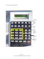
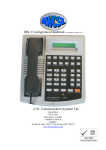
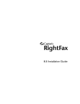
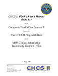
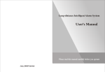
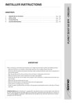
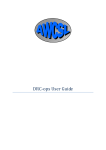
User Instruction Manual
DRC-32 Radio Controller Selcall and TETRA
A.W. Communication Systems Ltd.
Crook Barn
The Crook
Roweltown
Carlisle, Cumbria
England.
Tel: +44 (0) 1697 748777 Fax: +44 (0) 1697 748778
email: [email protected]
Contents
Unit Description. ............................................................................................................4
Multiple Audio Paths. ................................................................................................4
Individual Calling ......................................................................................................4
Status Information......................................................................................................5
Alpha Tags .................................................................................................................5
Headset Working........................................................................................................5
Common Headset Working........................................................................................5
Menu System..............................................................................................................5
Talk Through..............................................................................................................5
Talk Through [TT] Key .........................................................................................6
Facilities. ....................................................................................................................6
Handset.......................................................................................................................6
Unit Connections............................................................................................................7
Rear View of DRC-32...............................................................................................7
Power Supply Port. ....................................................................................................7
Auxiliary Port.............................................................................................................7
Record & Playback Port.............................................................................................7
Communication Port. .................................................................................................8
PTT.............................................................................................................................8
Headset Port. ..............................................................................................................8
Microphone Port. .......................................................................................................8
Telephone Line Port...................................................................................................8
Line Port.....................................................................................................................8
Menu System..................................................................................................................9
The Menu Architecture. ...........................................................................................11
The DRC-32 Display. ..................................................................................................12
DRC-32 Display.......................................................................................................12
User controls ................................................................................................................13
Volume Adjustment - Loudspeaker .........................................................................13
Setting the Selcall Outgoing Status ..........................................................................13
Changing a selected base station radio frequency ...................................................13
Connecting Channel ports (Channel Patching) ........................................................13
Setting the DRC-32 Channel Presentation...............................................................14
Setting the Default console Channel........................................................................14
Volume Adjustment - Headset .................................................................................14
Volume Adjustment - Handset.................................................................................15
Volume Adjustment - Default loudspeaker volume ................................................15
Keypad beeps ...........................................................................................................15
Set Time ...................................................................................................................15
Set Date ....................................................................................................................15
Display Contrast.......................................................................................................15
Set Microphone Source ............................................................................................16
Lamp & Key Test.....................................................................................................16
Set Ident Name Tags. ...............................................................................................16
Status Tags. ..............................................................................................................17
Set Channel Tag. ......................................................................................................17
Set Default Channel .................................................................................................17
-Page 2 –
© A.W. Communication Systems Limited 2004
Software Version......................................................................................................17
The Installation Menu ..............................................................................................17
Operation. .....................................................................................................................18
Taking Telephone Calls on Common Headset. .......................................................18
Making a Telephone Call .........................................................................................18
Telephone Patch. ......................................................................................................18
Calling a Mobile from the Keypad. .........................................................................19
Calling a Mobile from the Memory Stack ...............................................................19
Calling a Mobile from the Keypad When Calls Are Stored In Stack. .....................19
Calling More Than One Mobile - selcall .................................................................20
Calling More Than One Mobile – TETRA ..............................................................20
Finishing Calls .........................................................................................................20
Talk Through Facility. .............................................................................................20
Facility Control ........................................................................................................20
Location Call - Selcall..............................................................................................21
Interrogate Call – Selcall..........................................................................................21
Clear Function..........................................................................................................21
Notes:...........................................................................................................................22
-Page 3 –
© A.W. Communication Systems Limited 2004
Unit Description.
The DRC-32 desk-top controller from A.W. Communication Systems Limited
embodies the very latest hardware and software technology, thus maximising
functionality and reducing physical size of a radio control system operators unit to
that of a desk-top telephone unit.
Users of the DRC-32 can pre-select up to seven DS-32 channels for their individual
use. The operator can then select any one of the seen channels to transmit out on. A
monitor facility is provided to monitor the pre-selected channels without the transmit
function.
Only when a channel is selected will a transmission take place on that channel. Where
multiple operators have a channel in their pre-select groups, each operator can
monitor the outgoing audio from the other operators thus providing a fully informed
system.
The following is a brief description of the facilities available at your fingertips, all of
which are designed to enhance the radio facilities and ease the operator burden.
Please Note
The DRC-32 at your desktop will have been configured by your system supplier and
as such, may or may not have some of the features described herein enabled for your
use. Your supplier will help with any questions you may have regarding correct
operation and configuration.
Multiple Audio Paths.
The DRC1 will support operation using the built in loudspeaker and microphone, the
handset, which forms part of the unit, a plug in operator headset, and interconnection
with the telephone system. The DRC-1 also provides an audio input/output for use
with recording devices.
Individual Calling
Individual calling is the ability to call an individual mobile or portable radio terminal
using a uniquely allocated number. Having called the mobile resource, your
conversation with that mobile will not be overheard by the remainder of the fleet.
In an Individual calling system, a mobile wishing to communicate with a control room
operative makes a call using the unique number and the DRC-32 will either display
the call, or place it into a special queue to await operator call back.
It is also possible for the operator to call Groups of mobiles in order to make a
broadcast announcement or request.
-Page 4 –
© A.W. Communication Systems Limited 2004
Status Information
Status information forms part of the selective calling system. The status of a mobile is
indicated by appending one or more numbers to the mobile’s call- sign. In a similar
way, a control room operative can send a status code to a mobile to command a
required readiness state.
Alpha Tags
Alpha tags are text names, which can be allocated to individual identities, status
codes, and channels. These tags are intended to make the system readily
understandable by translating the numbers used within the system into text. By way of
example the incoming code 12349 can be tagged to display “Dog Van 3 Meal Break”
Headset Working
In busy control rooms it may be desirable to achieve quiet operation of the radio
system, and this can be achieved by plugging in an operator headset and microphone
combination. Once the operator is using the headset, then operation of the keypad
Transmit key will cause the operator’s voice to be transmitted. In receive mode, the
operator can choose to use the internal loudspeaker, or turn the loudspeaker off by
pressing the [LS] key.
Common Headset Working
If the operator is equipped with a headset, then the DRC-32 can also be
interconnected to the telephone system. This interconnection will have been
undertaken by your system supplier. By interconnecting the DRC-32 to the telephone
system, the operator can use the same headset to make and receive telephone and
radio calls. It is also possible to connect a mobile radio conversation directly to the
telephone system – see teleconnect.
Menu System
The menu system provides the operator access to many of the system facilities. The
menu is accessed by pressing the menu key and then using the up and down scroll
keys to move through the menu options. These are described in greater detail later.
Talk Through
Talk through is the term used for a facility which permits one mobile to speak with
another. It would be normal practise for the mobile requiring the talk through facility
to ask control to enable the facility. The DRC-32 can command talk through in several
-Page 5 –
© A.W. Communication Systems Limited 2004
ways which will depend upon what type of base station your service uses. This facility
is not available on TETRA channels.
Talk Through [TT] Key
The talk through key will enable the talk-through facility as described above. The key
will have been configured by your system supplier and there is no need here to
describe how it functions.
Facilities.
The [FAC]ilities key which can be found on the lower left hand side of the keypad
will have been programmed to control base station facilities. These facilities may be
unique to your service and as such is not possible for us to describe them here. By
way of example, your base stations may consist of a main equipment set, and a
standby equipment set. The standby set can be commanded to take over in the event
of equipment failure by operating the facilities key. When used with a TETRA
channel the Facility key selects either simplex or duplex calls.
Handset
In any mode of operation, picking up the handset will cause the DRC-1 to recognise
and use the handset microphone and ear-piece. For example, a control room
supervisor can pick up the handset and immediately communicate with a mobile
resource the operator is connected with.
-Page 6 –
© A.W. Communication Systems Limited 2004
Unit Connections.
The DRC-32 at your desk-top will have been installed and configured by your system
supplier. The connection information given below is offered as an aid to recognition
should any of the facilities become disconnected.
Rear View of DRC-32
Auxiliary Port
Power
Connector
Record & Playback Port
Comms
Foot PTT
Headset
Desk Telephone Instrument
Microphone
Line
Handset on Side
Power Supply Port.
Connection to the supplied modular power supply unit. Use only the supplied power
unit.
Auxiliary Port
The auxiliary port is used for connecting third party equipment such as modems.
Record & Playback Port.
Used for connection to recording and or playback devices.
-Page 7 –
© A.W. Communication Systems Limited 2004
Communication Port.
Used for programming and for system extension to other devices such as a PC based
dispatch system.
PTT.
Connect a foot operated press to talk switch to this port.
Headset Port.
Used for the connection of an operator headset to achieve quiet operation and
common headset functionality.
Microphone Port.
Used to connect a desk-top style microphone.
Telephone Line Port.
Used to connect the DRC-32 to a desk-top telephone instrument equipped with a
headset port to enable common headset working.
Line Port.
Used to connect the DRC-32 to the DS-32 or DS-micro switch shelf, which is then
connected through to the radio base stations or terminals.
-Page 8 –
© A.W. Communication Systems Limited 2004
Menu System
The operation of the DRC-32 falls into two main categories being:1, Accessing and setting embedded facilities such as volume levels and alpha tags.
These would normally be set once and used many times.
2, using the frequently used facilities such as making and receiving calls from
terminals and from the telephone system.
Access to the items in category one is achieved through the menu system. The menu
system is termed a “nested” menu because once the upper menu has been accessed;
there are multiple choices which can be scrolled through using the scroll up and scroll
down keys.
The menu key itself acts as a select key and indicates to the system what choice the
operator is making from the options listed on the screen. The [CLEAR] key acts as a
back-step key and its operation takes the operator one step backwards in the selection
process.
-Page 9 –
© A.W. Communication Systems Limited 2004
Keys used in the menu system.
Scroll Up
Scroll
Down
Menu
Clear
Alpha /
numeric
Keys
Volume
up
Volume
Down
-Page 10 –
© A.W. Communication Systems Limited 2004
The Menu Architecture.
The menu is nested in the following order.
Press Menu key.
Selcall Status
Set Radio Channel
Base radio channel
Connect group chans
Console channel 1-7
Default tx chan 1-7
Headset Volume
Handset Volume
Default Speaker Volume
Keypad Beeps
Set Time
Set Date
Display Contrast
Set Microphone Source
Lamp & Key Test
Set Ident nameTags
Set Status Tags
Set Channel Tags
Set Default Channel
Software Version
Installation Menu
Use Scroll Keys
Expert use only
It should be noticed that those functions, which will require frequent adjustment or are
operator dependant are placed at the top of the menu, and precede those items which
are used less frequently.
-Page 11 –
© A.W. Communication Systems Limited 2004
The DRC-32 Display.
The DRC-32 is equipped with a two line by twenty character LCD display. The
display is backlit for use in a dark environment and also has adjustable contrast for
improved visibility in a brighter environment
DRC-32 Display
1
2
3
4
5
6
15:51
7
The DRC-32 display consists of two lines of twenty characters. The display has both
static and dynamic information, and its appearance will change depending upon the
task being performed.
The numbers along the bottom row of the display are indications for the seven
“Channel” slots available to the operator. These indicate if a call is being received on
the specific channel, if the channel is selected by the operator, if the channel is
selected by another operator and if the channel is placed in a connect Group.
The top line of the displa y will show the details of the channel selected by the
operator and also the alpha tag for that channel. It also can display the current time
and the incoming call stack where calls are placed in the stack.
-Page 12 –
© A.W. Communication Systems Limited 2004
User controls
Volume Adjustment - Loudspeaker
The adjustment of the internal loudspeakers volume is achieved by using the volume
up [VOL UP], or volume down [VOL DN] keys without the need to access the menu
facility.
Setting the Selcall Outgoing Status
When the DRC-32 is used in a selcall signa lling system, it may be necessary for the
user to set the outgoing status digits sent to mobile resources. To change the outgoing
status digits, Press [MENU] to access the menu system, the first menu option
displayed is “Selcall Status”, press [MENU] again to select this item. The display now
changes to show the current status being used. Either enter a new status code from the
keypad or use the [↓] key to move through the status messages available. When the
desired status is selected, press [MENU] to store the value. The display returns to the
top level menu and the user has the choice to scroll to another menu option, or press
[CLEAR] to leave the menu system.
Changing a selected base station radio frequency
Where conventional radio base stations are connected to the channel ports of the DS32 /Ds-Micro system, the DS-32 operator has the facility to remotely change the radio
frequency of the base station (where this facility has been enabled by the system
installer). To change the base station frequency, press [MENU] to access the menu
system. Use the [↓] key to move down the menu until the top line of the display is
“Set Radio Channel”; press [MENU] again to select this item. The top line of the
display now shows “Base radio channel”, press [MENU] again to select this item. The
display now shows the current base channel selected. Enter a new channel using the
numeric keypad or by scrolling through the channels with the [↓] or [↑] keys. When
the appropriate channel has been selected press [MENU] to store the value. The
display then returns to the Set radio channels sub- menu and the user has the choice to
scroll to another menu option, or press [CLEAR] to move back up the menu system.
Connecting Channel ports (Channel Patching)
Within the DS-32 system, the operator has the facility to cross connect DRC-32
operator unit channels, thus enabling mobile resources on one channel to be connected
to resources on a second or multiple other channels. The connect facility is normally
controlled by a timer which is set by the system installer; at the expiry of this timer
any selected cross connected facility will be automatically removed. To connect
channels together press [MENU] to access the menu system. Use the [↓] key to move
down the menu until the top line of the display is “Set Radio Channel”, press
[MENU] again to select this item. Use the [↓] key to move down the menu until the
top line of the display is “Connected group chans”, press [MENU] again to select this
item. The display now shows the channel buttons 1 to 7 along the top row, to add a
channel into a connect group press the numeric key appropriate to the channel (i.e.
key 3 for channel 3) a letter G will now be displayed below the channel number
indicating that it is part of the connected group. Select the required number of
channels to e inserted in the group in the same way and then press [MENU] to
-Page 13 –
© A.W. Communication Systems Limited 2004
establish the channel connect. The display then returns to the Set radio channels submenu and the user has the choice to scroll to another menu option, or press [CLEAR]
to move back up the menu system.
Setting the DRC-32 Channel Presentation
The DRC-32 has the capacity to allow the user an option of monitoring and selecting
up to seven radio channels on the DS-32 switch. The pre-selected channels are
presented under the CH1 to CH7 buttons. The user can pre-select which switch
channels are used on his DRC-32 from the console channel menu option. To change
the channel pre-selection, press [MENU] to access the menu system. Use the [↓] key
to move down the menu until the top line of the display is “Set Radio Channel”, press
[MENU] again to select this item. Use the [↓] key to move down the menu until the
top line of the display is “Console channel 1-7”, press [MENU] again to select this
item. The display now shows the channel buttons 1 to 7 along the top row and the preselected switch channel number associated with the channel button along the bottom
row of the display. To change or add a pre-selected channel, press the numeric key
appropriate for the channel (i.e. key 3 for channel 3). The top row of the display now
shows the message “console chan 3 radio port” and the selected port number. Enter a
new port number from the numeric keys and press [MENU] to pre-select the channel.
The display now returns to the channel selection sub menu allowing the user to select
another channel button or press [CLEAR] to move back up the menu system.
Setting the Default console Channel
Upon start up the DRC-32 can automatically select a preferred operating channel; this
is especially useful when there is only one channel available to operators on the DS32 switch. To set the default switch on channel, press [MENU] to access the menu
system. Use the [↓] key to move down the menu until the top line of the display is
“Set Radio Channel”, press [MENU] again to select this item. Use the [↓] key to
move down the menu until the top line of the display is “Default tx chan 1-7”, press
[MENU] again to select this item. The display now shows “Default console TX” press
the numeric key for the channel you require as a default then press [MENU] to select
the item. The display then returns to the Set Radio channel sub menu allowing the
user to scroll to another item or press [CLEAR] to move back up the menu system.
Volume Adjustment - Headset
Press [MENU] to access the menu system. Use the [↓] key to move down the menu
until the top line of the display is “Headset volume”, press [MENU] again to select
this item. The display now changes to indicate the current volume setting as both a
bar-graph and number. Use [VOL UP] and [VOL DN] to adjust volume level. When
the desired volume is set, press [MENU] to store the value. The display returns to the
top level menu and the user has the choice to scroll to another menu option, or press
[CLEAR] to leave the menu system.
-Page 14 –
© A.W. Communication Systems Limited 2004
Volume Adjustment - Handset
Press the [MENU] key to access the menu system. Use the [↓] key to move down the
menu to Handset volume. Press [MENU] to select this item then use [VOL UP] and
[VOL DN] to adjust volume level. When the desired volume is set, press [MENU] to
store the value. The display returns to the top level menu and the user has the choice
to scroll to another menu option, or press [CLEAR] to leave the menu system.
Volume Adjustment - Default loudspeaker volume
The default loudspeaker volume setting determines the volume level the loudspeaker
will operate at when the unit is powered up. Press the [MENU] key to access the
menu system. Use the [↓] key to move down the menu to "Dflt speaker volume".
Press [MENU] to select this item then use [VOL UP] and [VOL DN] to adjust volume
level. When the desired volume is set, press [MENU] to store the value. The display
returns to the top level menu and the user has the choice to scroll to another menu
option, or press [CLEAR] to leave the menu system.
Keypad beeps
The keypad can emit one of two sounds, click or beep, or can be made silent. Press
[MENU] to access the menu system, then press [↓] until the chevron points to keypad
beeps. Press [MENU] to select this item then use the [↓] or [↑] and place the chevron
next to your choice {Pip, Click, or Off}. Press [MENU] to store your selection, then
[CLEAR] to exit the menu system.
Set Time
Press [MENU] to access the menu system, then [↓] until the chevron points to Set
Time. Press [MENU] to select this item. The display will now expect you to enter two
digits for the hour. Pressing clear will backspace and clear a digit at a time should you
wish to re-enter the numbers. Use the alpha- numeric keypad to enter the hour figures
then press [MENU] to store the numbers entered. Now the display will move down
and invite you to enter two digits for the minutes. Enter two digits then press [MENU]
to store your selection, and the display will move back to the menu option “set time”
press [CLEAR] to exit the menu system.
Set Date
Press [MENU] to access the menu system, then press [↓] until the chevron points to
set date. Press [MENU} to select. The display will change and expect you to enter two
digits for the day number. Enter two digits then press [MENU] to store your choice,
and then enter two digits for the month number and press [MENU] to store your
choice, and finally, enter two digits for the year and press [MENU] to store your
entry. Press [CLEAR] to exit the menu system.
Display Contrast.
To adjust the display contrast, press [MENU] to access the menu system, then [↓]
until the chevron points to Display Contrast. Press [MENU] to select this item, then
-Page 15 –
© A.W. Communication Systems Limited 2004
use [↓] or [↑] until the desired contrast level is observed. Press [MENU] to store your
settings, then, press [CLEAR] to exit the menu system.
Set Microphone Source
This item is likely to have been set by your system supplier; however circumstances
may require you to alter the setting should you connect a headset for the first time, or
have a headset failure and wish to revert to using the internal microphone.
Press [MENU] to access the menu system, then press [↓] until the chevron points to
Set mic source. Press [MENU] to select this item, then use the [↓] or [↑] to select the
microphone source, {Internal, or headset}. When the display indicates your desired
choice, press [MENU] to store your selection, then press [CLEAR] to exit the menu
system.
Lamp & Key Test.
The lamp and key test feature is a sub program used to test the buttons and illuminate
all of the lamps {L.E.D. devices}. This is a program which will run until cancelled.
The red “Transmit” key is used to stop the program and exit from this facility.
To access this facility, press [MENU] then [↓] until the chevron points to Lamp +
Key test. Press [MENU] to select this item and the sub program will run. The program
will illuminate the five lamps which should alternate between red and green in colour.
The button test takes the form of the display indicating the “column” and “Row”
number of any key pressed. For example, pressing the 3 key causes the display to
show 3x because the 3 key is part of the keypad matrix. Pressing the “group” key
causes the display to indicate C1.1 because the group key is the first key in column
one. Pressing the Transmit key shuts down the program and causes the DRC-32 to
reset.
Set Ident Name Tags.
Ident name tags are text labels which are associated with selective calling identities,
for example individual identity 23123 may be assigned “John Smith” or “Dog Van”.
Press [MENU] to access the menu system then [↓] until the chevron points to “set
ident tags”. Press [MENU] to select this item. The display will now change and
expect you to input the identity number you wish to tag. Be aware that the numbers of
digits expected are indicated by the number of dashed lines appearing in the display,
and so if three lines are showing, enter three digits. Having entered your digits press
[MENU] to select the ident ity. Two possibilities now exist.
1, an identity has not been previously entered for the chosen ident ity number, in
which case the Tag: line will be empty.
2, an existing tag will be in place which you can choose to keep, press [MENU] to
keep the existing tag and exit, or [CLEAR] to erase and edit the existing tag.
To enter a tag into a blank space, use the alpha-numeric keypad in the same way you
use a cellular telephone keypad to send an SMS. E.g. each press scrolls the key
-Page 16 –
© A.W. Communication Systems Limited 2004
options. The Zero key will insert a text space into your tag. Once the tag has been
entered, press [MENU] to store the tag.
To edit an existing tag, use the clear key, which will back-space along the existing tag
removing one character per press, or press any alpha key to erase the whole tag. At
your chosen point, begin to enter your new text as above.
Status Tags.
A status tag is a text label which can be associated with a status code. Status codes are
part of the selective calling message field. Assuming that vehicle identity number 123
has been tagged as “Dog Van”, then the reception of a status code from the same
vehicle would indicate Dog Van -Meal Break for status 02 if so tagged.
Press [MENU] to access the menu system, then press [↓] until the chevron points to
Set status tag. Press [MENU] to select the item. Enter the status code number you
wish to tag. The number of dashed lines will indicate how many digits are to be
entered. Having entered the digits press [MENU] to select the code, and then enter the
text for the tag. When the text is entered, press [MENU] to store the tag, press
[CLEAR] to exit the menu system.
Set Channel Tag.
A channel tag is a text name given to the radio channel the DRC-32 has access to. For
example, the selected channel can be simply displayed as “Ch:1”, or “Ch: Town Ctr”.
To set a channel tag, press [MENU] to access the menu system, then press [↓] until
the chevron points to set channel tag. Press [MENU] to select the item then enter three
digits for the channel number. Use leading zeros, e.g. 001 for channel 1. Having
entered the three digits press [MENU] to select the channel number and proceed to
enter the tag text. Press [MENU] to store the entered text, and then press [CLEAR] to
exit the menu system.
Set Default Channel
This item is used in the selection of the initial channel to be used at power on of the
DS-32 and will be normally set by the system installer.
Software Version
This item simply displays the installed software version number which your support
company may request when giving telephone support. Press [MENU] to access the
menu system, and scroll down using the [↓] key until the chevron points to Software
Version. Press [MENU] to select option and the display will indicate the version
information. Press [CLEAR] twice to exit the menu system.
The Installation Menu
The installation menu gives access to critical system settings and is likely to have
been pin code protected by your system supplier. There are no user adjustments
available within this menu.
-Page 17 –
© A.W. Communication Systems Limited 2004
Operation.
Taking Telephone Calls on Common Headset.
Your DRC-32 can be interconnected with a local desk-top telephone instrument, via
which access to the telephone system can be gained. The desk-top telephone will
continue to operate in the same way with the exception that the DRC-32 headset can
now also be switched to the telephone.
When the telephone rings, press its pick-up key to answer the call, then press
[SELECT] on the DRC-32. Pressing the DRC-32 select key will cause the headset to
transfer from radio operation to telephone. The display will show the message
“telepho ne” and the select LED will extinguish. If the DRC-32 operator has turned
off the DRC-32 loudspeaker, it will automatically re-engage when the headset is
transferred to telephone.
The re-engagement of the loudspeaker provides continued monitoring of radio traffic
whilst the operator is using the telephone system. The headset can be returned to radio
operation by a second press of the [SELECT] key. It should be noted that the transfer
of the headset back to radio will not cause the telephone call to hang-up, and so the
operator can swap between radio and telephone call several times to take further
telephone information and give command instructions over the radio.
To hang-up the telephone call use the pick-up key or close key on the telephone
instrument, and transfer the headset back into radio operation.
Making a Telephone Call
To make a telephone call, press [SELECT] on the DRC-32, and then the pick-up key
on the telephone instrument. After dial tone is heard in the headset, use the telephone
instrument dial pad to dial the required telephone number. To close the call press the
telephone instrument pick- up key and then press [SELECT] on the DRC-32 to
transfer the headset back to radio operation. During the progress of the telephone call,
the radio traffic continues to be audible through the DRC-32 loudspeaker, and the
headset may be transferred back to radio without losing the telephone call by simply
pressing [SELECT].
Telephone Patch.
The DRC-32 has the ability to connect a mobile resource via their radio set to the
telephone system. The mobile is then able to hear and speak via the radio system onto
the telephone system. To achieve this, the operator has to set up the call manually, and
then transfer the call to the radio system.
If a mobile requests such a call, then whilst the mobile is available on air and the
appropriate channel on the DRC-32 is selected, press the [SELECT] key to transfer
the headset to the telephone system. Press the telephone pick- up key and a dial tone
should be heard in the headset. Use the telephone’s dial key pad to dial the number.
Speak to the called party and ask them to hold, press the DRC-32 [SELECT] key to
transfer your headset back to radio, and speak to the mobile. Press the [TELCON] key
to interconnect the mobile radio to the telephone system.
-Page 18 –
© A.W. Communication Systems Limited 2004
Whilst the connection is in place, the DRC-32 operator can hear both sides of the
conversation, but can only speak whilst the [TRANSMIT] key is pressed. Upon
conclusion of the telephone to radio patch, close down the call on the telephone by
pressing the pick- up key to release the line, then press the [TELCON] key on the
DRC-32 to revert to normal operation.
Calling a Mobile from the Keypad.
To call a mobile using the keypad, first select the appropriate radio channel by
pressing the channel button and checking that the channel alpha tag is shown in the
top line of the display, then enter the required number of digits for the mobile
resource identity. Upon entry of the last digit, if an alpha tag has been programmed
for this resource, the tag will appear as a confirmation you have entered the correct
number. Press [CALL] and the selective calling code will be transmitted.
Depending upon how your selective calling system has been configured, the display
will either display “calling” followed immediately by “connected” at which point you
should speak to the mobile whilst pressing the [TRANSMIT] key, or
The display will show “Ringing” followed by “connected” or “no answer”. Connected
indicates the acknowledge message has been received from the mobile, and speech
communication is possible. Use [TRANSMIT] key when speaking, or if “no answer”
is displayed, the mobile has not answered and may be out of range, not on air, etc. The
operator may press [CALL] again to retry, or press [CLEAR] to close down.
Calling a Mobile from the Memory Stack
The memory stack stores ten received calls. The operator can scroll up and down
through the stored calls by using the [↓] and [↑] keys. Whatever call-sign is presently
displayed, pressing the [CALL] key will call that mobile as long as the appropriate
channel is selected upon the DRC-32.
The system will go through the connected or ringing- connected procedure and a
conversation will become possible if the mobile responds. At the end the conversation
press [CLOSE] key, at which point the call will remain in the stack. To remove the
call from the stack, press [CLOSE] once again.
Calling a Mobile from the Keypad When Calls Are Stored In Stack.
Even if the call stack has stored calls awaiting action, using the keypad to enter an
identity number will cause the system to switch from looking at the call stack, to
using the data entered at the keypad to make the call. The procedure is then identical
to that described above {Using Keypad}
-Page 19 –
© A.W. Communication Systems Limited 2004
Calling More Than One Mobile - selcall
The selective calling system enables groups of mobiles to be called. Issuing a group
call will not get a ringing- no answer type of response. Connected will always be
shown as a result of a group call.
To make a group call the [GROUP] key is pressed as part of the ident ity input from
the keypad. The place within the identity string at which the [GROUP] key is pressed
determines how many mobiles are called. By way of example, consider a system
where the operator normally inputs three digits for the identity code. Inputting 001
will call mobile number one only. Input 00 [Group], and the nine mobiles 001 to 009
will be called. Similarly, 0G will call the 99 mobiles between 001 and 099. GG will
call 999 mobiles.
Calling More Than One Mobile – TETRA
Within the TETRA system facilities are available to call groups of mobile resources
providing that the individual units ha ve been configured with the same group number.
To initiate a TETRA group call, select the TETRA channel and then enter the group
identity digits finally press the [GROUP] key to initiate the call.
Finishing Calls
When a call to a mobile comes to an end, it may be finished and the mobile placed
back into standby mode by pressing [CLOSE] key. Where the handset has been used
for calls, placing the handset back on the rest will close the current call.
Talk Through Facility.
To enable mobiles to communicate directly with each other the talk through facility
needs to be turned on. Pressing [T/T] key turns on the talk through facility and the TT
led will illuminate. A second operation of the [T/T] key will cancel the talk through
facility. This facility is not available on TETRA channels.
Facility Control
Your system supplier may have configured extended control of your base station unit.
This extended control may take several forms, and therefore, is not detailed here.
Operation of the [FAC] key will activate whatever extended control has been
provided and the Fac led will illuminate. On TETRA channels the [FAC] key is used
to select between simplex (PTT) calls or duplex calls. To initiate a duplex call, select
the TETRA channel, dial the digits required, press the FAC button and then press the
call button. Duplex calls can only be made using the handset or headset options. If the
internal microphone or the desk microphone is used then the call is set up as a duplex
call but the operator still acts as if in PTT mode requiring use of the PTT for transmit
audio.
-Page 20 –
© A.W. Communication Systems Limited 2004
Location Call - Selcall
If the mobile is equipped with a GPS location receiver, then it can be interrogated for
a location without driver intervention. Enter the ident ity number of the desired
mobile, then press [LOC]. A special selective call is issued to the mobile which will
respond without alerting the driver, and send location data.
Interrogate Call – Selcall
To interrogate a remote mobile resource for its current selcall status, the [INT] key is
used instead of the call key. The operation is the same as for the location facility.
Clear Function
The [CLEAR] key is used to remove identity numbers from the display if an error is
made during the identity number entry.
-Page 21 –
© A.W. Communication Systems Limited 2004
Notes:
-Page 22 –
© A.W. Communication Systems Limited 2004