1
4140XMPT2
PARTITIONED
SECURITY
SYSTEM
WITH SCHEDULING
N~
ZLDHVEO
? W93
.-
——
—..
..
TABLE
sYsTEMovERvlEw
OF CONTENTS
.......... ...................................3
Bypassing
PRoEcTloNzoNEs
. .... . .. .. ... .. .. . .. .. ...l9
Quick Bypass ... .. .. .. ... .. .. ..... . . .... .. .. . ...... .. . .. ......l
Displaying Bypassed Protection Zones .. .. . .. ... . .. ...2 &
SUMMARYOFARMING COMMANDS . .. ... .. .. . .. ... .......21
Global Arming. .......... ........ ............. ..................21
ARMING PERIMETERONLY(STAY)
.... .. . ..... .. .. . .......22
ARMING PERIMETER ONLY (INSTANT) ....................23
ARMINGALLPROTECTDN(AWA~
.. .. ... .. .. ..... . .. .. ...24
ARMING ALL PROTECTION (MAXIMUM) ...................25
DISARMINGTHE SYSTEMANDSILENCING
ALARMS.26
USING~E
KEYSWITCH . .. .. .... . .. .... . .. ... . .. . .. .. ... ......27
CHIME~DE
.. .... .. .. . .. .. .. .. ... .. .. .. .... . .. .. .. .... . ..........28
VIEWING CENTRAL STATION MESSAGES . .. ... ... . .. ...29
PANlc KEYs . .. .. .. .... . .. ...... .. . .... .. .. ... .. .. .. ..... .. .. .... ..3o
TEsTINGwEsYsTEM
... .. .... . .. .... .. . ..... . . .. ....... .. .. ..3l
USINGSCHEDULES . .... .. .. ..... .. .. ... .. .. ... . ... .. .. ... .... ..~
Delaying ~eCl=ing
~me . .... .. . .... .. . . ..... . .. .. ... .. ..X
TemporaryOpen/Close Schedules .... . . . ... .. .. . .......34
Programming Temporary Schedules .....................35
PROGRAMMING DEVICE TIMERS ....... ....................37
mouBLEwNDmloNs
.... .. ... .. .. .... . .. .. . . .. . .. .. ... .. ....39
FIRE ALARM SYSTEM ........................ ...................4l
NFPARE~MMENDATONS
.. .. .... . .. .... . . . .... . .. .. .. .....42
EMERGENCYEVACUATION .. .. .. ... .. .. ... . . . .... .. .. .. .....&
GLOSSARY .... . ... .. .. . .. .. .. .... . .. .... .. .. ... .. .. .... . .. .. ......U
SUMMARY OF AUDIBLE NOTIFICATION ...................45
Genera l... .. .... ... .... ... .... .. ... .... ... ... ... ... .... ... ... ... .. 3
A Partitioned System .. .... .. . .... .. .. ... . . .. ... .. .. .. ..... ...3
Zones .. .. ... ... .. . ...... .. .. ... .. .. .. .. .. . .. .. .. .. .... . .. .. ...... . 4
Consoles .... ......... ... .... ... ...... .... ... . .. ..................4
Burglary Protection ..... ................ ...................... 4
Fire Protection ............ ............... .. .....................5
Alarms . .... .. .. .. ... .... .. .... . .... .. .. ..... .. .. .. .. .. ....... .. ...5
Memo~ofAlarm ...... .. .. . .. .. .. .. . .. .. .. . . .. ... .. .. .. ..... .. . 5
Seti.Help Feature . .. .... .. ... .. .. .... . .. ... . .. . .... .. .. . .......5
Using Schedules .......................... .....................6
DeviceTlmers ... .. .. .. ... .. .... .. . .. .. .. .. .. .. ... ...... . .. .. .. . 6
SECURllYCODES
&AUTHORITYLEVELS . ... .. . .. ... .. . . 7
General .... ..... ....... ... ... ... ... .... ... ... . ..... .... ...... ... .. 7
Duress tie
. ... ... .... . .. .... .. .. ... .. .. ... .. .. .... .. . .. ...... . 7
Qui&Arming ... . .. .. ... .. .. .... .. ..... .. .. . .. .. .. .... . .. .. .. .. . 7
Authoriiy Levels .. .. .. .... . .. .... .. . .... .. . . ... .. .. ..... .... .. . 8
ToAdd AUser . ...... .. .. . .. .. .. ... .. .. .... .. . .. .. .. .. ..... .. ..lO
To Change AUser's Cde .. .. .. ... .. .. .. . .. .. ... .. .... ... ..l 1
To Delete AUser .. .. .... .. . .. .. .. ... .. .. .. . .. .. .. .. .. ... .. ....l 1
ENmYExlTDEMYs
. .. .... .. ... .. .. ... .. .. . ... . .. .... .. . .. .. ..l2
ACCESS DOOR CONTROL ................................ .....13
ACCESSING OTHER PARTITIONS(GOTO) . .. . .. . .. . .....14
sYsmMsTAms
DlsPMYs . .. .. ... .. .. .. . .. .. ... .. .. .. .....l5
FUNCTIONSOFTHECONSOLE
.. .. ... .. .. ... .. .. ... .... . ....16
WECKING FOROPEN ZONES ... .. .. . .... .. . .. .. . ....... .. ..l8
Displaying All Zone Descriptors ...........................l8
-2-
SYSTEM
General
OVERVIEW
Convatulationson your ownershipOf a .VISTA partitioned Security System. You’ve
made a wise decision in choosing it, ford represents
the latest
technology
today. Ademco
is the worlds
largest manufacturer
and millions of premises
are protected
by Ademco systems.
in security protection
of security systems
This system offers you three forms of protection:
burglary,
fire and emergency.
To
realize the system’s full potential, it is important that you feel comfortable
in operating
it. Your system
consists
of at least one Console
which provides
full control of
system
operation,
various
sensors
which provide
perimeter
and interior burglary
protection,
plus a selected
number
of strategically
placed
smoke
or combustion
detectors designed
to provide early warning in case of fire.
The system uses microcomputer technology to monitor all protection zones and
information
for display on the Console(s)
system status and provides appropriate
used with the system,
and initiates
appropriate
alarms.
Your system
may also have
been programmed to automatically transmit alarm or status messages over the
phone lines to a central alarm monitoring station.
A Partitioned
System
s~rnplystated!a partitionedsy~ternshare: one physicalalarmsystemamongmaw
different us.ers~each with their own requirements” APPllcatlons ran9e from a two
family dwelling to a factory/office complex. For the most part, you as a user need not
know about other users and their structure in the system, but from time to time, you
may see display messages which indicate the system is in use by another user. Do
not be concerned, this is normal. Refer to the ACCESSING OTHER PARTITIONS
section for additional information.
-3-
SYSTEM
Zones
OVERVIEW
Your system’s sensing devices have been assigned to various “zones”. For
example, the sensing device on your Entry/Exit door may have been assigned to ~
zone 01, sensing devices on windows in the master bedroom to zone 02, and so
on. These numbers will appear on the display, along with an alpha descriptor for
that zone (if programmed), when an alarm or trouble conditionoccurs.
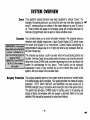
Consoles
Your consoles allow you to control all system functions. The consoles feature a
telephone style (digital) keypad and a Liquid Crystal Display (LCD) which shows
~
:;f~pQg~*~~;’fijj.~***f#
::: the nature and location of all occurrences. Console display backlighting is
programmable to always stay on or to light only when a key is pressed, then turn
y#r9mi$e,$;:it’Y*d:@*i*:
tti$:a$$ off a few mmutes later.
The consoles also feature a built-in sounder which will sound during alarms and
%%$?ll%:#@oii*dld+tifi#.Y+tifi:
‘!w.i;gti$ifl~~tjg,m:y.%:x
Wj:ji:&troubles. It will also “beep” during certain system functions, such as during entrylexit
‘fiMFRf*m\w#f14:RwAp%i
delay times, during CHIME mode, and when depressing keys to arm and disarm the
;:::~~~,,~~~~,,,;Ww‘WM?aR$w;:
,.... ....... . ~~~~
~~~~~~~~~~~~~~
system (to acknowledge the key press). These sounds can be optionally
;:,~:jj;&::~*wlkn;j’;;;; #:xz . suppressed in some of your consoles (so as not to disturb other users of the
system). Ask your installer if this has been done.
iw~i~tidwtiwwtkflwtiw
Burglary
Protection
The burglary protection portion of your system must be turned on or “armed” before
it will sense burglary alarm conditions. Your system provides four modes of burglary
protection: STAY, AWAY INSTANT and MAXIMUM, and even allows you to
BYPASS selected zones of protection while leaving the rest of the system armed.
The system also provides a CHIME mode, for alerting users to the opening and
closing of doors and windows while the system is disarmed. Refer to the other
sections of this manual for procedures for using these features.
-4-
SYSTEM
Fire protection
Alarms
Memory
OVERVIEW
The tire protectionportionof your seCUW system (if used) is a~aw on and will
sound an alarm if a fire condition is detected. Refer to the FIRE ALARM SYSTEM
section for important information concerning fire protection, smoke detectors and
planning emergency exit routes from your house.
when an alarmOCCUrS!both the console and external sounders will sound! and the
console will display the zone(s) causing the alarm. If your system is connected to a
central monitoring station, an alarm message will also be sent. To stop the alarm
sounding, simply disarm the system.
of Alarm when an alarmconditionoCQJrs!the consoledisPlaYs the number(s) of the zone(s)
that caused the problem, and displays the type of alarm (ex. FIRE, ALARM). It
remains displayed until it is cleared by disarming the system (entenng your user
code + pressing [~].
If the system was armed when the alarm occurred, the user
code + [~
must be entered twice: once to disarm the system, a second time to
clear the display.
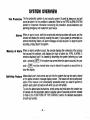
Self-Help
Feature
Abbreviateduser’sinstructionsaW builtintothe sYs@rnthatcan be easilYviewed
on the alpha console’s message display screen. This feature will prove particularly
useful if this manual is not conveniently accessible when you need to perform a
seldom used system procedure with which you are not familiar.
To view the abbreviated instructions, simply press and hold down the function key
of interest until the description starts to a pear (about 5 seconds) and then release
it. Refer to the FUNCTIONS OF THE C 8 NSOLE section for detailed descriptions
of each key function.
-5–
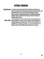
SYSTEM
Using Schedules
Device Timers
OVERVIEW
Your system may have been programmed with schedules for automatically arming,
disarming and activating various devices and/or performing other system functions at predetermined times. Users can modify some of these schedules by manually
delaying a closing time, using tern orary schedules, or by programming special user
schedules. Refer to the USING S E HEDULES section at the end of this manual for
scheduling related procedures.
The system provides up to 20 “timers” which can be used to control various devices, such
as lights or appliances. These timers are similar in concept to the individual appliance timers
that might be purchased at a department store. The devices that can be controlled are
programmed into the system by the installer. Up to 16 of these devices can be
programmed. Refer to the PROGRAMMING
-6-
DEVICE TIMERS section for procedures.
SECURITY
“
veral Information
Duress
CODES
& AUTHORrlY
LEVELS
At the time of installation, you were assigned an authority level and a personal fourdigit security code, known only to you and yours. The security code must be
entered when arming and disarming the system. The authority level defines the
system functions that you can perform.
As an additional safety feature, other users that do not have a need to know your
code can be assigned different security codes, and each user can be given a
different authority level. Users are identified by “user numbers”, which are assigned
when assigning a user’s security code.
All codes can be used interchangeably when performing system functions within the
limits of each code’s authority level (a system armed with one user’s code can be
disarmed by another user’s code), with the exception of the Operator Level C code.
Code This feature is intended for use when you are forced to disarm or arm the system
under threat. When used, the system will act normally, but can silently notify the
central station of your situation, if that service has been provided. The duress code
is pre-assigned by the installer during installation (auth. level 6).
Important: This code is useful only when the system is connected to a central
station.
Quick Arming
❑
key can be
Note that if “Quick Arming” was programmed by the installer, the
pressed in place of the security code when arming the system. The security code
must always be used to disarm the system, however.
-7–
SECURITY
Authority
Levels
CODES
& AUTHORl~
LEVELS
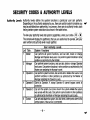
Authority levels define the system functions a particular user can perform.
Depending on the authority assigned to you, there are certain system functions you
may be prohibited from performing. In summary, there are six authority levels, each
having certain system restrictions as shown in the table below.
❑ ❑
+
.
To view your authority level and system capabilities, enter your code +
The console will display the partition(s) that you are authorized to operate, and your
user number and authority level in each partition.
,Lvl
1
Title
Master
2
Manager
3
Operator A
4
Operator B
5
Operator C
6
Duress
User Authority
Levels
System
Functions
Can perform all system functions, and can add, delete or change
Manager and Operator level users. Can perform system functions in other
partitions as authorized by the Installer.
Can perform system functions, and can add, delete or change Operator
level users. Can perform functions in other partitions as authorized by the
Master user assigning the Manager’s code.
Can perform system functions, but cannot add or delete other users. Can
perform functions in other partitions as authorized by the Master or
Manager assigning the Operator’s code.
Same as Operator A, except Operator B cannot bypass zones of
protection.
Can arm the system, but cannot disarm the system unless the system
was armed with this code. Can perform same function in other partitions
as authorized by the Master or Manager assigning this user’s code.
Can arm and disarm the system, twt also sends a silent panic alarm to the
central station, if that service is connected.
-8-
_
SECURITY
b
CODES
& AUTHORITY
LEVELS
General Rules on “ A user may not delete or change the user code of the SAME or HIGHER authority
than which he is assigned.
hority Levels and
A
user may only ADD users to a LOWER authority level.
Changes :
A user may assign user access to other partitions only if he himself has access to
those partitions.
. The only way to assign a user’s authority level is by usin the “Add A User”
procedure. To change a user’s authority level, that user must ?irst be deleted, then
added again.
. A user can only be DELETED or CHANGED from within the partition he is
assigned.
. User numbers must be entered as 2-digit entries. Single digit user numbers must
be preceded by a “O”(example, 03, 04, etc.). Security codes are entered as 4digit numbers.
Before assigning a security code, be sure it does not conflict with any DURESS
code.
●
Note: When adding, changing or deleting users, all other consoles in that partition
will displa “User Edit Mode – Please Stand By”, and key depressions (ex~ept
Panic) at ti! ose consoles will be ignored. Panic key depressions will cause an alarm
and terminate user entry.
To Exit User
seconds.
Edit Mode, press either @
-9-
or ~,
or don’t press any key for 10
SECURITY
CODES
& AUTHORIW
LEVELS
1. Enter Master or Manager code and press the CODE key.
To Add a User
2.
3.
Enter the new user% 2-digit User Number (01-99).
Enter 4-digit security code for that user. The following prompt will appear.
Enter the authority ievel, 1-6, for this user withinthis partition.
3=operator A
&ZE~er
..cp.rater.
IEEGEl
~
4
!
This prompt will appear if a 58OO series button transmitter has been supplied and has not yet been
assigned to a user. Press 1 if a button transmitter will be assigned to this user.
IEmzl
~
r
Global Rrm ?
O=NO, l= YES
!
\
EREl
=
If assigning a button transmitter, this prompt will appear. Enter the button’s
zone number (see your installer for zone number).
If you as a user have access to other partitions, the console will prompt for ability of this new user to
access (GOTO) those partitions. Press O (NO) or 1 (YES). If no, the system activates this user code
and exits “Add a User” mode. if yes, the console prompts for the Global Arm option for this user,
Press 1 (YES) if this user will be allowed to arm more than one partition via global arm prompts. Press
O if global arming is not desired for this user.
I Multi-flccess ?
B= NO, l=VES
L
5X%2X.
If access groups/access schedules have been assigned by the installer, this prompt will appear. See
your installer for information concerning access groups.
The console now prompts for the user’s access to the next partition. Again press O or 1. If no, the
next partition number appears, etc. If yes, the system will automatically assign a user number for use
in that partition and will prompt for the authority level and global arm option for this user within the
partition displayed (see previous steps), When finished, the next partition number will be displayed.
When all partitions have been displayed, the
has been assigned, and will display the user
Note that the “G” following the authority level
for this user in the displayed partition . The
changed or deleted.
-1o-
console will scroll through all partitions to which access
number, authority level and global arm option for each.
indicates that the global arm feature has been selected
“’- indicates the partition from which the user can be
SECURITY
Change a User’s 1.
Code 2.
3.
4.
CODES
& AUTHORITY
LEVELS
Enter Master or Manager code and press the CODE key.
Enter the user number to have its code changed.
Enter the new code for that user.
The system will recognize that the user number is already in use and will prompt
whether or not this is a new user. Press O (NO). The system will confirm that the
change is allowed based on authorization level, and if so, will put the new code
into effect.
me’s own code, the system will prompt for the new
Note that if changin
code to be reentered. f his prevents accidentally changing a high level code.
To Delete a User
1.
2.
3.
4.
Enter Master or Manager code and press the CODE key.
Enter User Number to be eliminated.
Enter Master or Manager code first entered.
The system will remgnize that the User number is alread in use and will prompt
to confirm that it shoukt be deleted. Press O (NO) or 1 (Y 1!S).
If yes, that user’s code will be removed from all partitions to which it was
assigned, and all authorization levels and other information about that user will
be deleted. Note that a user can only be deleted from the partition in which it
was first assigned, and can only be deleted by a user with a higher authority
level. A User cannot delete himself.
-11-
ENTRY/EX9T
General
Information
DELAYS
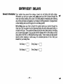
Your system has preset time delays, known as exit delay and entry delay.
Whenever you arm your system, exit delay gives you time to leave through the
main door without setting off an alarm. Exit delay begins immediately after entering
any arming command, and applies to all modes of arming protection. If programmed,
a slow beeping will sound throughout the exit delay period.
Entry Delay gives you time to disarm the system when you reenter through the
main door. But the system must be disarmed before the entry delay period ends, or
an alarm will occur. The console will beep during the entry delay period, reminding
you to disarm the system. You can also arm the system with no entry delay at all by
using either INSTANT or MAXIMUM arming modes. These modes provide greater
secirity when sleeping or while away fo; extended periods of time. See your
installer for your delay times.
Exit Delay 1: m
Entry Delay 1: m
Exit Delay 2: m
Entry Delay 2: m
-12-
e
ACCESS
teral Information
DOOR
CONTROL
Your system maybe set up such that a locked access door (such as in a lobby) can be
unlocked using a console command. Ask your installer if this has been done in your system.
To activate this relay, enter your security code and press
seconds.
-13–
❑. The
door will unlock for 2
ACCESSING
OTHER
PARTITIONS
(GOTO Command)
To Access Another
Partition
Each console is assigned a default partition for display purposes, and will show
only that partition’s information. But, if the user is authorized, a console in one
partition can be used to perform system functions in another partition by using the
GOTO command. Note that only those partitions authorized and programmed by the
installer can be accessed in this manner.
❑
followed by
To GOTO another partition, enter your security code, then press
the desired partition number (1-8).
The console will remain in the new partition until directed to go to another partition, or
until 120 seconds has elapsed with no keypad activity. Entering partition number O
will return the console to its original pattition.
-14–
SYSTEM
STATUS
DISPLAYS
For Fixed-Word Consoles
AWAY
Ail burglaw zones, interior& perimeter, are armed.
STAY
perimeter burglary zones, such as windows& doors, are armed.
INSTANT
perimeterbwlafy zones armedandefW delayis turnedoff.
BYPASS
One or more burglaryProtectionzones have been Wwssed.
NOT
READY
Appears when burglary portion of the system is not ready for arming (due to open
protection zones).
READY
The @@arY
NO AC
j:~e~
AC
CHIME
BAT
Swternis readyto be armed.
when AC power has been cut off. System is operating on backup battety
Appears when AC power is present.
Appearswhenthe CHIME feature is activated.
LOW battery condition in a wireless sensor (if ID number displayed) or low system
battery (if no ID number displayed).
ALARM
Nwars whenan intrusionhas beende@C@d and the Systemis armed(also
appears during a Fire alarm). Accompanied by the protection zone ID in alarm.
CHECK
Appears when a malfunction is discovered in the system at any time or if a fauit is
detected in a FiRE zone at any time or in a DAY/NiGHT burgia~ zone during a
disarmed period. Accompanied by a dispiay of zone number in troubie.
FIRE
xars
whenafire alarmis present. Accompanied by a dispiay of the zone in
-15-
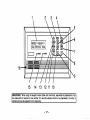
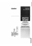
FUNCTIONS
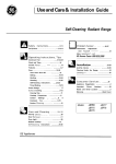
1.
2.
3.
4.
OF THE CONSOLE
-
9.
Display (LCD). Displays protection point identification and system
status, messages, and user insfmlfons.
10. -1
KEV: Allowatheenlryof additionalusercodesthatcanbe
giventootherusersof the system. TMs keyis alsousedto perform
someschedulingfunctions.
~
KEV: Disarms tie b.rglaty portion of thesystern, si[ence~
alarms and audible trouble indicators, and dears visual alarm trouble
afWr the problem has bean cormclacf.
~1
KEV: Completely arms both perimeter and interior
burglary pmtaction for backup protection by sensin an Intruder’s
movements through rotect@ interior areas as we1 I as guardhg
doors, windows, eto. I%e arnvdscan enterthro.gh an en? delay
zone without causing an alarmif the system is disarmed be ore the
entry delay time expires.
l-l
KEV: Arms the perimeter burglary protection, guarding
5.
~]
6.
-]
KEV: Removes individual protection zones fmm being
monitored by the system. Db.plays previously bypassed protection
zones.
7.
WI
KEY: Turnson & off the CHIME mode. When on, any
entry through a delay or WrfmeEr zone while the system is disarmed
will cause alone to sound at the console(s).
KEV:Teststhesystem
❑ KEV: Permits ARMING
11,
-]
KEV: When depressed prior to arming the system, the
oonsolewill dsplay all open protectionzones. This key is also used to
display all zone descriptors that have been programmed for your
system, by holdingthe key down for at least 5 seconds.
12
~
INSTANTi1 KEV: Armsin mannersimilarto STAY mode. but turns
L
off the entry delay period, offeringgreater securitywhile rnsideand not
expecting any late arrivals. An alarm will occur immediately upon
opening any perimeter protectionpoint, irroludingentry delay zonee.
13.
-]
KEY: Arms in manner similar to AWAY mode, but
eliminates the entry delay period, thus providingmaximum protion.
An alarm will occur immediately upon opening any protection point,
includingentry dday zones,
(GREEN) On some consolas, this lights
14. POWER INDICATOR:
when primary power is on. If off, s“stem is operatin on its badwp
battery power, CALL YOUR INST 1 LLER IMMEDIA ? ELY, On other
types of consoles, lit indicab3ssystem is ready to be armed.
RED tit when the system has bean armed
15. ARMED INDICATOR:
{STAY. AWAY. lNSTA~Tor hlMUM).
16. iNTER”NALSOUNDER: Source of audible internalwarningand
doors,,windows and other perimeter pmtactbn Pokr=, and sounds an
alarm If one is owned. Interior protection is not armed, which albwe
movement within your house without causing an alarm. Late arrivals
can entef through an entry dday zone without causing an alarmif the
systsin is dsarmed before the entry delay time expires.
8.
KEVS0-9 Usedto enteryourindvidualsecurityaccessOJde(s).
ALPHADISPUV WINDOW:A 2-line, 32-oharacter Liquid Crystal
and alarm sounderifdisarmed.
confirmationsounds,as well as alarms(see “Summaryof Audible
Notifications”).
of the system without use of a security
code (“Quick Arm”, if programmed).
-16-
234
1
\
\
\
RRRED””” RLIW’
\
MAxlMIMTEsl
“+
YOU 17FWEXIT IYOU
I 1’ [
I
● POWER
ARMED
PANIC
I
I
I
I
f
\
\
m
16—
15
14
13
12 11 10
IMPORTANT!: When using the keypad to enter codes and commands, sequential key depressions must
be made within 3 seconds of one another. If 3 seconds elapses without a key depression, the entry is
aborted and must be repeated from its beginning.
1
-17-
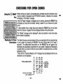
CHECKING
❑
READY Before arming your system! alI protected doors! WindOWSand other protection zones
must be closed or bypassed (see BYPASSING
section). Otherwise the console
‘ey
will display a “Not Ready” message.
If the Not Ready message is displayed prior to arming, pressing the READY key
?xw#6iPg#ti8/&&#f~#
j!; will display all zones that are faulted, making it easier for you to secure any open
zones
?$@&tii@&a$Ri%!m:m
!
~
%%@&$$w$ti+:%%w@?
%;;,
~$~#f~&&**fwtiAt4*ffi,
o show faulted zones, simply press and release the READY key (do not enter
‘?M,*;~*wtii~,~;*#Otietiihs: ~de first)”secure or bYP=s the zones disPlaYed before =mif19 the sYstef-11’
%!#mMi%iq4M4;::fh4ffti:6:{ The “Ready” message will be displayed when all protection zones have been
‘i;%;%!w.~:wwwmm
3: either closed or bypassed.
:;:~~~$iw!~:w;?i$wqqi;
Displaying All Zone The Alpha Consoles can also display all the zone descriptors that are programmed
Descriptors in your system by pressing the READY key and holding down for at least 5
seconds*. The abbreviated instructions for the READY key will appear first,
followed by the descriptors programmed for your system. Displaying all descriptors
is useful when you need to know the zone number of a particular zone, as when
bypassing zones.
* Note that the “Disarmed-Ready to arm” message must be displayed before zone
descriptors can be displayed.
thing
the
FOR OPEN ZONES
@Jtim
TYPICAL CONSOLE KEYPAD
q
,“,~~~~~:,,$
m“
m
‘&R”DyK”
-18-
‘
~:~j,
~
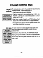
BYPASSING
PROTECTION
ZONES
This key is used when you want to arm your system with one or more zones
intentionally unprotected. The system must be disarmed first.
1. Enter your security code and press the BYPASS key.
2. Enter zone number(s) for the zones to be bypassed (e.g., 01, 02, 03, etc.).
Important! All single-digit zone numbers must be preceded by a zero (for
example, enter 01 for zone 1).
3. When finished, the console will display the word BYPASS and along with each
bypassed zone number. Wait for these zones to be displayed before arming.
4. Arm the system as usual. Bypassed zones are unprotected and will not cause
an alarm when violated while your system is armed.
Your system may allow you to automatically bypass all open (faulted) zones
withouthavingto enterzone numbersindividually.Ask yourinstallerifthisfeatureis
activeforyoursystem.
To use this feature, enter your security code, press the BYPASS key, then press
key and stop. In a few moments, all open zones will be displayed along with
the
the word BYPASS. Wait for all bypassed zones to be displayed, then arm the
system as usual.
❑
-19-
BYPASSING
Displaying
PROTECTION
ZONES
Bypassed (For determining what zones have been previously bypassed)
Zones
1. Enter security code and press the BYPASS key.
2. Wait for all bypassed zones to be sequentially displayed.
3. Bypassed zones can be displayed only when system is disarmed.
Limitations
●
.
Fire or emergency zones cannot be bypassed.
Arming the system before bypassed zones
bypasses.
are displayed
TYPICALCONSOLE
KEYPAD
b
h
h
b
THESE KEYS NOT PRESENT
ON ALL CONSOLES -
T
-20-
FIEHY1/
Ei@Ha”
rzhm?l
Cpglgl
TO BYPASS ZONES
● ENTER CODE,
●
●
PRESS BYPASS
KEY,
ENTERZONE Nos.
WAIT FOR
BYPASSED ZONES
TO BE DISPLAYED
BEFORE ARMING
cancels
all
SUMMARY
:
~mary of Arming
Modes
COMMANDS
The following table lists the four different arming modes and the results of each.
Arming
Mode
AVVAY
STAY
INSTANT
MAXIMUM
Global Arming
OF ARMING
Exit Delay
Yes
Yes
Yes
Yes
Features For Each Arming Mode
Perimeter Armed Interior Armed
EntrY Delay
Yes
Yes
Yes
Yes
No
Yes
Yes
No
No
Yes
Yes
No
The Global Arming option may have been programmed for use by some users. If
Global Arming was enabled for use with your security code, a console prompt
(messa e) will appear after pressin one of the arming function keys (STAY,
INSTAN$- , AWAY, MAXIMUM, OFF). I$oIIowthe console prompts to continue arming
the system. See your installer for detailed instructions on the use of this feature.
If global arming does not apply to your security code, use the procedures described
in the following pages.
ARMING
PERIMETER
(With Ent~
Using the
❑ STAY
~_
ONLY
Delay ON)
Use this W when YOUare SW@I hornetbut might expect someone to use the
main door later.
Enter your security code and press the STAY key.
The console will beep three times and will display the armed message.
The system will arm and will sound an alarm if a door or window is opened, but
you may otherwise move freely throughout the house.
Late arrivals can enter through the main door without causing an alarm, but they
must disarm the system within the entry delay period.
TYPICAL CONSOLE KEYPAD
b Qql
THESE KEYS NOT PRESENT
ON ALL CONSOLES -
PPJW
7
-22-
~
ARMING
PERIMETER
(With Entry
❑
ONLY
Delay OFF)
Using the Use this key when you are staying home and do not expect anyone to use the main
INSTANT Key door.
1. Enter your security code and press the INSTANT key.
The console will beep three times and will display the armed message.
The system will arm and will sound an alarm if a door or window is opened, but
you may otherwise move freely throughout the house. The alarm will also sound
immediately if anyone opens the main door.
lVPICALCONSOLE
KEYPAD
dmml’
h
fi @’-iJ-,Jp
&EE!;EJ~
THESE KEYS NOT PRESENT
ON ALL CONSOLES ~
~
-23-
m-m’.,.,
ARMING
ALL PROTECTION
(With Entry Delay ON)
9$
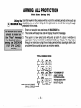
Using the Usethis key when no one will be staying home.
Enter your security code and press the AWAY key.
The console will beep twice and will display the armed message.
The system will arm and will sound an alarm if a door or window is opened, or if
any movement is detected inside your house. You may leave through the main
door during the exit delay period without causing an alarm. You may also reenter
through the main door, but must disarm the system within the entry delay period.
TYPICALCONSOLEKEYPAD
fi~’;~
tibml
%
‘
h
FI &l ~
h
@lg
PANic
THESE KEYS NOT PRESENT
ON ALL CONSOLES 3
-24-
THE AWAY KEYARMS
KW-RRFEM
Z?sy’”’
ARMING
ALL PROTECTION
(With Entry Delay OFF)
❑
4
Using the Usethiskeywhenthepremiseswillbe vacantfor extended periods of time such as
vacations, etc., or when retiring for the night and no one will be moving through
MAXiMUM Key protected interiorareas.
Enter your security code and press the MAXiMUM key.
The console will beep twice and will display the armed message.
The system is now armed and will sound an alarm if a door or window is
opened, or if any movement is detected inside your house. You may leave
through the main door during the exit delay period without causing an alarm, but
an alarm will be sounded as soon as someone reenters.
TYPICAL CONSOLE KEYPAD
THE MAXIMUM KEY
ARMS THE ENTIRE
SYSTEM (INCLUDING
THE MAIN DOOR,WITH
NO ENTRY DEtiY)
THESE KEYS NOT PRESENT
ON ALL CONSOLES
t
-25.
DISARMING THE SYSTEM
AND SILENCING ALARMS
Using the The OFF key is used to disarm the system and to silence alarm and trouble sounds.
Key 1. To disarm the system and siience burgiary or fire aiarms, enter your
security code and press the OFF key. The Ready message will be displayed
and the console wiil beep once to confirm that the system is disarmed.
To Siience a FiRE aiarm, enter your security code and press the OFF key.
The security code is not needed to silence FIRE alarms.
See “SUMMARY OF AUDIBLE NOTIFICATION” section for information which
wiil help you to distinguish between FIRE and BURGLARY alarm sounds.
2. If an alarm has occurred, and the premises is safe to reenter, note the zone
number displayed on the console and repeat step 1 to restore the Ready
message display (to clear the “Memory of Alarm”). If the Ready message will not
display, go to the displayed zone and remedy the fault (close windows, etc.). if
the fault cannot be remedied, notify the alarm agency.
❑ OFF
TYPICAL CONSOLE KNPAD
~T~~
Q&J5s
n~~&J
g
THESE KEYS NOT PRESENT
ON ALL CONSOLES
-26-
k
TO DISARM SYSTEM:
● ENTER COOE
● PRESS OFF KEY
Qimgl
PANC
USBNG THE KEYSWITCH
General Your system may be equipped with a keyswitch for use when arming and
disarming. A red and green light on the keyswitch plate indicate the status of your
system as follows:
Green
Light:
Red
Light:
Lights when the system is disarmed
and ready to be armed
(no open zones). If the system is disarmed and the green
light is off, it indicates the system is not ready (one or more
zones are open).
Lit Steady:
Slow Flashing:
Rapid Flashing:
Lights when system is armed or memory of alarm exists.
System is armed in AWAY mode.
System is armed in STAY mode.
Memory of alarm. An alarm has occurred.
Arming
To arm in the AWAY mode, turn the key to the right for 1/2 second and release.
Consoles will beep twice and the red light will stay on steady.
To arm In the STAY mode, turn the key to the right and hold for longer than 1
second, then release. Consoles will beep three times and the red light will flash
slowly.
Disarming
To disarm the system, turn the key to the right and release. If an alarm has
occurred, the red light will be flashing rapidly (memory of alarm).
-27-
CHflME MODE
Using the
❑ Key
,~~@*,~*,~~~&
#j&j@fi
‘fifi?wfi,ti&&diti~tg&tiflI~ij::
:,:~~~~mq;$~t~~ls.;;;
~“y~y;y;~”~<-~f~~~;;,
E
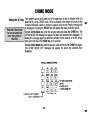
Your system can be set to alert you to the opening of a door or window while it is
disarmed by using CHIME mode. When activated, three tones will sound at the
Console whenever a door or window is opened, and the Not Ready message will
be displayed. Pressing the READY key will display the open protection points.
TO turn Chime Mode on, enter the security code and press the CHIME key. The
?H IME M.ODE ON message WIII appear for about two seconds ~hen disappear. TO
display this message again (to determme whether chime mode IS on or off), simply
press and hold down the CHIME key for 5 seconds.
To turn Chime Mode off, enter the security code and press the CHIME key again.
The CHIME MODE OFF message will appear for about two seconds then
disappear.
lvPIcAL CONSOLE KEYPAD
hmm?!
THESE KEYS NOT PRESENT
ON ALL CONSOLES
h FI t_=IE!Et’~y~;:::EMODE
D El El El “‘RESS
c“’”’
““
-9
L
-28-
PANIC J
~
VIEWiNG
leral
Information
CENTRAL
STATiON
MESSAGES
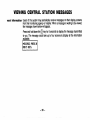
Users of the system may periodically receive messages on their display screens
from their monitoring agency or installer. When a message is waiting to be viewed,
the message shown below will appear.
❑
key for 5 seconds to display the message transmitted
Press and hold down the
to you. The message could take up to four screens to display all the information
available.
m
-29-
PANIC
(FOR MANUALLY
Using
Panic Keys
ACTIVATING
KEYS
SILENT
AND/OR
AUDIBLE
ALARMS)
Your system may have been programmed to use special key combinations to ~
manually activate panic functions. The functions that might be programmed are Silent
Emergency,
Audible Emergency,
Personal
Emergency,
and Fire. See your installer
for the function(s) that may have been programmed for your system.
Active Panic Functions
will send a silent
A silent emergency
(Your installer should note which
alarm signal to the central station, but there
function
is active in your system)
will be no audible alarms or visual
%eys
Zone
Function
displays.
95
1 and *
An audible emergency will sound a loud,
3 and #
96
steady alarm at your console and at any
external sounders that may be connected
99
* and #
(ALARM
plus a zone number would also
A“
be displayed).
emergency
alarm will send
A personal
b
I
I
1 an emergency message to the central
Im
May not be praeen~on your console(s).
station (if connected) and will sound at
To use a paired key panic function,
Consoles, but not at external bells or
simpiy
press
both
keys
of the
sirens.
assigned
pair at the same time. if
your consoie(s)
have iettered
keys Afire aiarm wili send a fire alarm message
for
panic
functions,
press
the to the central station and wili uniquely
designated
key and hoid down for sound external bells and sirens (FIRE
at ieast 2 seconds
to activate
the plus a zone number wouid also be
displayed).
panic function.
-30-
TESTING
THE SYSTEM
(TO BE CONDUCTED
WEEKLY)
Using the The TEST key puts your system into Test mode, which allows each protection point
5 TEST Key to be checked for proper operation,
❑
1. Disarm the system and close all protected windows, doors, etc. READY should
be displayed.
2. Enter your security code and press the TEST key.
3. The external sounder should sound for 3 seconds and then turn off. If the
sounder does not sound, it maybe due to dialer communication activity. Wait a
few minutes and try again. If the sounder still does not sound, CALL FOR
SERVICE
IMMEDIATELY.
4. The console will sound a single beep every 15 seconds as a reminder that the
system is in Test mode. Each time a protection zone is faulted (opened), the
console should beep three times. If the sounder does not sound, ‘CALL’ FOR
SERVICE IMMEDIATELY.
TYPICAL CONSOLE KEYPAD
d GIEIEI
15
d
d rxlmm
THESE KEYS NOT PRESENT
ON ALL CONSOLES ~
T
‘p”’=
-31-
USETHE TEST KEYTO
TESTYOUR SYSTEM
WEEKLY
TESTING
Testing Your System
THE SYSTEM
1. Open and close each protected door and window in turn and listen for three
beeps. The identification of each faulted protection point should appear on the ~
display.
2. Walk in front of any interior motion detectors (if used) and listen for three beeps
as movement is detected. The identification of the detector should appear on the
display when it is activated.
3. Follow the manufacturer’s instructions to test all smoke detectors to ensure that all
are functioning properly. The identification of each detector (or the zone number
of the zone assigned to the detector) should appear on the display when each
is activated.
4. When all protection points have bee,n checked, there should be no zone
identification numbers displayed. If a problem is experienced with any protection
point (no confirming sounds, no display), CALL FOR SERVICE IMMEDIATELY.
5. Turn off Test mode by entering the security code and pressing the OFF key.
-32-
USING SCHEDULES
~ying the Closing Your system’s programmed schedules may automatically arm the system at a
Time predetermined
time.in the eventa usermuststayon the premiseslaterthanusual,
users with master or manager authority levels can manually delay the automatic
arming (closing) time up to 2 hours.
To delay the closing time
1. Enter your security code (master or manager
❑
authority levels only).
Press the
key, followed by 82.
A menu prompt will be displayed, asking for the number of hours of delay.
Enter the desired number of hours of delay, 1 or 2, then
press X to accept the entry. The system will automatically
mu
exit this mode.
Note that the delay is from the scheduled closing time, not from the time the
command is entered.
Important:
The selected delay cannot be reduced once it is set. A 1 hour
delay can be increased to 2 hours, though.
4. The system will automatically send a message to the central station informing
2.
3.
them that the programmed
-33-
schedule has been changed.
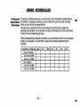
USING SCHEDULES
Temporary
Open/Close
Schedules
Temporary schedules allow you to override the normal schedules programmed by
theinstaller.TemporaryschedulesCanbe in effectfor UPto one week, and take
effectas soon as theYare pwrarnrned.
Schedules are comprised of an arming (closing) time window and a disarming
(opening) time window. A time window is simply a defined period of time, at the end
of which arming or disarming will occur.
Before programming a temporary schedule, use a worksheet similar to the one below
to plan your schedule. This will make it easier when actually programming the
schedule.
Arm/Disarm
Windows
Mon
Disarm Window
Starf Time HH:MM
Stop Time
HH:MM
Arm Window
Start Time HH:MM
Stop Time HH:MM
-34-
Tue
Wed
Thu
Frl
Sat
Sun
~
Programming
Temporary
Schedules
Temporary schedules only affect the partition from which it is entered. Temporary
schedulescan be reused at la@r dates simply W scrolliw (W pressingW to the
DAyS? prompt(describedbelow)and activa~w the wprop~ate days. This should
be considered when defining daily time windows. Note that only users with authority
level of manager or higher can program temporary schedules.
To program temporary schedules:
1. Enter your security code.
key followed by 81.
2. Press the
3, The following prompts will appear.
❑
m
The cursor will be positioned on the tens of hours digit of
the start time for Monday’s disarm window. Enter the
to move to the minutes field. The
desired hour. Press
minutes are entered in the same manner. The AM/PM
indication is changed by hitting any key, O-9, while the
cursor is under the letter A/P position. Repeat for the stop
time entry. Press the key to move to the arming window
for Monday.
Press #to move to the next screen display without making
changes.
●
●
-
The cursor will be positioned on the tens of hours digit of
the start time for the arm window. Repeat the previous
steps to enter the start and stop time for Monday’s arming
window.
–35-
After the windows for that day have been
system will prompt for disarm and arm time
next day. Repeat the procedure for all days
When all of the days have been completed,
ask which days are to be activated.
EEEEEl
ETEl
completed, the
windows for the
of the week.
the system will
This is the prompt that actually activates the temporary
schedule,
and allows the temporary
schedule
to be
customized to a particular week’s needs. To select the days
which are to be activated, enter the desired number 1-7
(Monday = 1). An “X” will appear under that day, indicating
the previously entered schedule for that day is active.
Entering a day’s number again will deactivate that day,
Pressing O will turn all days on/off.
The temporary schedule will only be in effect for the days
which have the letter x underneath them. As the week
progresses, the days are reset to the deactive state.
When completed, press * to exit the temporary schedule
entry mode.
-36-
~
PROGRAMMING
DEVICE
TIMERS
meral Information Device timers consist of an ON time & an OFF time, and selected days of the week in which
they are active. There are up to 20 timers that can be used to control various devices, such
as lights or appliances. Your installer will have programmed the appropriate devices into the
system (up to 16 devices can be programmed).
Each timer controls a single device (designated as an output number) that you select. For
example, timer 1 might be set to turn the porch lights on at 7:OOpm and turn them off at
11 :OOpm. Timer 2 might turn on the air conditioner Monday-Friday at 4:30pm to cool the
premises before you arrive at 5:OOpm, and turn it off at 10:OOpm when you are retiring for
the night. If desired, different timers can control the same device. For example, timer 2
could be used Monday-Friday
as in the previous example, and timer 3 could be set to turn
the air conditioner on and off at different times Saturday and Sunday.
To enter the device timer menu mode:
1.
Enter your security code.
2.
Press the
3.
The following series of prompts will appear.
❑ key followed by 83.
EzzEl
m
Up to 20 timem can be programmed. Each timer is identified by a
number 1-20. Enter the desired timer number to be programmed
(1-20). Press to accept entry.
●
Enter the desired output device number (1-1 6). See your
installer for device numbers. As the number is entered, the
device’s description will appear.
To delete a previously programmed timer, enter 00 as the output
number.
-37-
I
00 ON TIME ?
00:00 PM
I
Enter the time you want the device turned on using 00:0111:59 format. When the display shows the desired time, press
the * key to move to the AM/PM field. Press any key O-9 to
change the AM/PM indication.
Enter 00:00 if this timer is not being used to turn something ON
for the days selected below. (ex. using one timer to turn lights on
one day and using another timer to tUm them off on another day).
Enterthe time you want the device turnedoff using00:0111:59 format. When the display shows the desired time, press
the * key to move to the AM/PM field. Press any key O-9 to
change the AM/PM indication.
Enter 00:00 if this timer is not being used to turn something OFF
for the days selected below. (ex. using one timer to turn lights on
one day and using another timer to turn them off on another day).
I
00 Days? MTWTFSS
Hit 0-7
X
X
I
Select the days on which the device is to be activated
by
entering 1-7 (Monday = 1). An “X” will appear under that day,
indicating the output for that day is active. Entering a day’s
number again will deactivate that day. Pressing O will turn all days
on/off. The outputs will only be in effect for the days which have
the letter x underneath
them. As the week progresses,
the
selected
days are reset to the deactive
state, unless the
permanent option is selected
completed, press to continue.
(next screen
prompt).
When
●
Answerina 1 [ves) means the svstem will continue executina this
timer on ~co;tinuous basis. An-answer of O means execute-each
day’s output only once.
-38-
TROUBLE
Typical ‘Check’
Displays
Note that zone numbers
88-91 represent problems
with wireless receivers,
which are not user
serviceable. CALL FOR
SERVICE IMMEDIATELY.
●
CONDITIONS
The word CHECK on the Console’s display, accompanied by a rapid “beeping” at
theConsole,indicates
thatWe is a troubleCondition
inthesystem.
To silence the beeping sound for “check conditions, press any key.
1. A display of “CHECK” accompanied by a display of “CALL SERVICE”
indicates that a problem exists with the s stem that eliminates some of the
protection. CALL FOR SERVICE IMMEDIA v ELY.
2. A display of “CHECK” accompanied by a display of one or more zone
descriptors indicates that a problem exists with those zone(s)*. First, determine if
the zone(s) displayed are intact and make them so if they are not. If the problem
has been corrected, the display of the zone descriptor(s) and CHECK should
disappear. If not, key an OFF sequence (Code plus OFF) to clear the display. If
the display persists, CALL FOR SERVICE IMMEDIATELY.
3. A display of “’COMM. FAILURE” at the Console indicates that a failure has
occurred in the tele~hone communication ~ortion of vour
system. CALL FOR
.
SERVICE IMMEDIATELY.
4.
A display of “SYSTEM
LO BAT”, accompanied
by a once per minute
“bee in “ at the Console indicates that a low system battery condition exists.
CAL i’%F R SERVICE IMMEDIATELY.
A display of “LO BAT and a zone descriptor, accompanied b a once per
minute “beeping” at the Console indicates that a low battery concl’ition exists in
the wireless transmitter** displayed. CALL FOR SERVICE IMMEDIATELY.
6. A display of “MODEM COMM’* indicates that the control is on-line with the
m!Eizz15”
central station’s remote computer. The control will not operate while on-line.
-39-
TROUBLE
Power Faiiure
Non-Aipha
Console
Displays
CONDITIONS
If the POWER indicator is off, o crating power for the system has stopped and is
inoperative. CALL FOR SERVI 8 E IMMEDIATELY. If the POWER indicator is on,
but the message “AC LOSS” is displayed, the Console is operating on battery
power only. If only some lights are out on the premises, check circuit breakers and
fuses and reset or replace as necessary. CALL FOR SERVICE IMMEDIATELY if
AC power cannot be restored.
The following displays will appear on non-alpha consoles when the associated
troubleCondition(previouslydescribed)is present
97 = CALL SERVICE
FC = COMM FAILURE
BAT = SYSTEM LO BAT (if no zone number) or LO BAT (if zone number shows)
CC = MODEM COMM
NO AC = AC LOSS
–40-
~
FIRE ALARM
General
In Case Of Fire
Alarm
Silencing
A Fire
Alarm
SYSTEM
(IF INSTALLED)
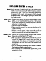
Your fire alarm system (if installed) is on 24 hours a day, providing continuous
protection. In the event of an emergency, the installed smoke and heat detectors will
automatically send signals to your Control/Communicator,
triggering a loud,
interrupted sound from the Console. An interrupted sound will also be produced by
optional exterior sounders. A FIRE message will appear at your Console and remain
on until you silence the alarm.
1. Should you become aware of a fire emergency before your detectors sense the
problem, o to your nearest Console and manually initiate an alarm by pressin
the panic i ey pair assigned as FIRE emergency (if programmed by the installer7
and hold down for at least 2 seconds.
2. Evacuate all occupants from the premises.
3. If flames and/or smoke are present, leave the premises and notify your local Fire
Department immediately.
4. If no flames or smoke are apparent, investigate the cause of the alarm. The zone
descriptor of the zone(s) in an alarm condition will appear at the Console.
1. Silence the alarm by entering your code and pressing the OFF key. To clear the
display, enter your code and press the OFF key again.
2. If the Console does not indicate a READY condition after the second OFF
sequence, press the READY key to display the zone(s) that are faulted. Be
sure to check that smoke detectors are not responding to smoke or heat
producing objects in their vicinity. Should this be the case, eliminate the source
of heat or smoke.
3. If this does not remedy the problem, there may still be smoke in the detector.
Clear it by fanning the detector for about 30 seconds.
4. When the problem has been corrected, clear the display by entering your code
and pressing the OFF key.
-41-
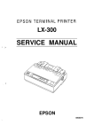
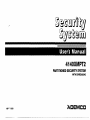
NATIONAL FIRE PROTECTION ASSN.
RECOMMENDATIONS
ON SMOKE DETECTORS
With regard to the number and placement of .wnoke/heat detectors, we subscribe to
the recommendations contained in the National Fire Protection Association’s Standard
#74 noted below.
Early warning fire detection is best achieved by the installation of fire detection
equipment in all rooms and areas of the household as follows: A smoke detector
installed outside of each separate steeping area, in the immediate vicinity of the
bedrooms and on each additional story of the family living unit, including basements
and excluding crawl spaces and unfinished attics.
In addition, it is recommended that the householder consider the use of heat or smoke
detectors in the living room, dining room, bedroom(s), kitchen, hallway(s), attic,
furnace room, utility and storage rooms, basements and attached garages.
BEDIWMM
-1
9
■
Smoke Detectors for MinimumProtecticm
9
Smoke
A
Heat-Activated DeIectore
Detectore
for Adddional Proteci”H
SASEMENT
I
-42-
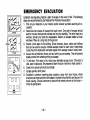
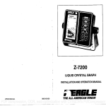
EMERGENCY
EVACUATION
Establish and regularly practice a plan of escape in the event of fire. The following
stem are remmmended by the National Fire Protection Association:
1. Plan on your detector or your interior and/or exterior sounders warning all occupants.
2. Determine two means of escape from each room. One path of escape should
lead to the door that permits normal exit from the building. The other maybe a
I
m
❑ n
❑
o
window, should your path be unpassable. Station an escape ladder at such
windows if there is a long drop to the ground.
3. Sketch a floor plan of the building. Show windows, doors, stairs and rooftops
that can be used to escape. Indicate escape routes for each room. Keep these
routes free from obstruction and post copies of the escape routes in every room.
4. Assure that all bedroom doors are shut while you are asleep. This will prevent
deadly smoke from entering while you escape.
5. Try the door. If the door is hot, check your alternate escape route. [f the door is
cool, open it cautiously. Be prepared to slam the door if smoke or heat rushes in.
6. Crawl in the smoke and hold your breath.
7. Escape quickly; don’t panic.
8. Establish a common meeting place outdoors, away from your house, where
everyone can meet and then take steps to contact the authorities and account for
those missing. Choose someone to assure that nobody returns to the house —
many die going back.
FRONT
-43-
GLOSSARY
The following glossary of terms are used throughout the manual.
ARM/DISARM: “Armed’”simply means that the burglary portion of your system is
turned ON and is in a state of readiness. “Disarmed” means that the burglary ~
system is turned OFF, and must be rearmed to become operational. However, even
in a “disarmed” state, “emergency”
and “fire” portions of your system are still
operational.
KEYPAD: This is the area on your Console containing numbered pushbuttons
similar to those on telephones or calculators. These keys control the arming or
disarmin
of the system, and perform other functions which were previously
describe c?in this manual.
ZONE: A specific area of protection.
PARTITION:
An independent group of zones that can be armed and disarmed
without affecting other zones or users.
BYPASS: To disarm a specific area of burglary protection while leaving other areas
operational.
ZONE: An area of protection containing doors most frequently used to
DELAY
enter or exit (typically, a front door, back door, or door from the garage into the
building). The dela zone allows sufficient time for authorized entry or exit without
causing an alarm. 1 onsult your installer for the entry and exit delay times that have
been set for your system during installation and record them on the separate sheet
provided in this manual.
DAY/NIGHT
ZONE: An area of protection whose violation causes a trouble
indication during the disarmed (DAY) mode and an alarm during the armed (NIGHT)
mode.
-44-
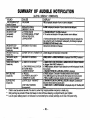
SUMMARY
OF AUDIBLE
●
NOTIFICATION
If bell is used as external sounder, fire alarm is pulsed ring; burglary/audible emergency is steady ring.
*•
Entry warning may consist of three short beeps or slow continuous beeping, as programmed by your installer.
● **
Loss of system battery power is not indicated or annunciated by the console (warnings are for loss of AC power only).
-45-
LJL NOTICE:
“FEDERAL
COMMUNICATIONS
This
is a “GRADE
COMMISSION
A“ svstem.
(FCC)
Part
15
STATEMENT”
1
rhis equipment has been tested to FCC requirements and has been found a~ceptable for use. The FCC requires the following I
itatemint for your information:
rhis equipmentgeneratesandUsesradiofrequency energy and if not installed and used properly, that is, in strict accordance with ‘~
manufacturer’s instructions, may cause interference to radio and television reception. It has been type tested and found to comply with
he limits for a Class B computing device in accordance with the specif ications in Part 15 of FCC Rules, which are designed to provide
However, there is no guarantee that interference will not
easonabie protection against such interference in a residential installation.
ccur in a particular installation. If this equipment does cause interference to radio or television reception, which can be determined by
urning the equipment off and on, the user is encouraged to try to correct the interference by one or more of the following measures:
●
If using an indoor antenna, have a quality outdoor antenna installed.
Reorient the receiving antenna until interference is reduced or eliminated.
●
Move the receiver away from the control/communicator.
●
Move the antenna leads away from any wire runs to the amtrol/communicator.
●
s Plug the rmntrolkommunicator into a different outlet so that it and the receiver are on different branch circuits.
f necessary, the user should consult the dealer or an experienced radio/television technician for additional suggestions.
‘he user or installer may find the following booklet prepared by the Federal Communications Commission helpful: “Interference
{andbook”
‘his booklet is available from the U.S. Government Printing Office, Washington, DC 20402.
“he user shall not make any changes or modifications to the equipment unless authorized by the Installation Instructions or User’s
flanual. Unauthorized changes or modifications could void the user’s authority to operate the equipment.
IN THE EVENT OF TELEPHONE
OPERATIONAL
PROBLEMS
In the event of telephone operational problems, disconnect the control by removing the plug from the RJ31 X wall jack. We recommend
that your certified installer demonstrate disconnecting the phones on installation of the system. Do not disconnect the phone
connection inside the controlkommunicator. Doing so will result in the loss of your phone lines. If the regular phone works correctly
after the control/communicator has been disconnected from the phone lines, the controlkommunicator has a problem and should be
returned for repair. If upon disconnection of the controkcrmmunicator, there is still a problem on the line, notify the telephone company
that they have a problem and request prompt repair service. The user may not under any circumstances (in or out of warranty) attempt
any service or repairs to the system. It must be returned to the factory or an authorized service agency for all repairs.
-46-
“FEDERAL
COMMUNICATIONS
COMMISSION
(FCC}
Part 68 NOTICE
This euui~mentcom~lieswith Part 68 of the FCC rules. On the frontcoverof this eaui~ment is a labelthat contains.amona
- ‘her information, the FCC registration number and ringer equivalence
.{ormation must be provided to the telephone company.
lThis equipment
number (REINj for this equipment.
If requested,
thi~
uses the following jacks:
An RJ31 X is used to connect this equipment
to the telephone
network.
The REN is used to determine the quantity of devices which may be connected to the telephone line. Excessive RENs on
the telephone line may resultin the devices not ringingin response to an incomingcall. In most, but not all areas, the sum
of the RENs should not exceed five (5.0). To be certain of the number of devices that may be connected to the line, as
determined by the total RENs, contact the telephone company to determine the maximum REN for the calling area.
If this equipment causes harm to the telephone network, the telephone company will notify you in advance that tempora~
discontinuance
of service may be required. If advance notice is not practical, the telephone company will notify the
customer as soon as possible. Also, you will be advised of your right to file a complaint with the FCC if you believe
necessary.
The telephone company may make changes in its facilities, equipment, operations, or procedures that could affect the
operation of the equipment. If this happens, the telephone company will provide advance notice in order for you to make
the necessary modifications in order to maintain uninterrupted service.
If trouble is experienced with this equipment, please contact the manufacturer for repair and warranty information. If the
trouble is causing harm to the telephone network, the telephone company may request you remove the equipment from
the network until the problem is resolved.
components in this product, and all necessary repairs must be made by the manufacturer.
Other repair methods may invalidate the FCC registration on this product.
This equipment cannot be used on telephone company-provided
coin service. Connection
to Party Line Service is
There are no user serviceable
subject to state tariffs.
This equipment
is hearing-aid
compatible.
When programming or making test calls to an emergency number, briefly explain to the dispatcher
Perform such activities in the off-peak hours; such as early morning or late evening.
-47-
the reason for the call.
THE
LIMITATIONS
WARNING!
OF THIS
ALARM
SYSTEM
Alhile this system is an advanced design security system, it does not offer guaranteed protection against burglary or fire or otb
}mergency. Any alarm system, whether commercial or residential, is subject to compromise
or failure to warn for a variety of reas~
‘or example:
intruders may gain access through unprotected openings or have the technical sophistication to bypass an alarm sensor or
disconnect an alarm warning device.
Intrusion detectors (e.g. passive infrared detectors), smoke detectors, and many other sensing devices will not work without power.
Battery operated devices will not work without batteries, with dead batteries, or if the batteries are not put in properly. Devices
pewered solely by AC will not work if their AC power supply is cut off for any reason, however briefly.
Signals sent by wireless transmitters may be blocked or reflected by metal before they reach the alarm receiver. Even if the signal
path has been recently checked during a weekly test, blockage can occur if a metal object is moved into the path.
A user may not be able to reach a panic or emergency button quickly enough.
While smoke detectors have played a key role in reducing residential fire deaths in the United States, they may not activate or
provide early warning for a variety of reasons in as many as 35’%0of all fires, according to data published by the Federal Emergency
Management Agency. Some of the reasons smoke detectors used in conjunction with this System may not work are as follows.
Smoke detectors may have been improperly installed and positioned. Smoke detectors may not sense fires that start where smoke
cannot reach the detectors, such as in chimneys, in walls, or roofs, or on the other side of closed doors. Smoke detectors also may
not sense a fire on another level of a residence or building. A second floor detector, for example, may not sense a first floor or
basement fire. Moreover, smoke detectors have sensing limitations. No smoke detector can sense every kind of fire every time. In
general, detectors may not always warn about fires caused by carelessness and safety hazards like smoking in bed, violent
explosions, escaping gas, improper storage of flammable materials, overloaded electrical circuits, children playing with matches, or
arson. Depending upon the nature of the fire and/or the locations of the smoke detectors, the detector, even if it operates as
anticipated, may not provide sufficient warning to allow all occupants to escape in time to prevent injury or death.
Passive Infrared Motion Detectors can only detect intrusion within the designed ranges as diagramed
in their installation manual.
Passive Infrared Detectors do not provide volumetric area protection. They do create multiple beams of protection, and intrusion can
only be detected in unobstructed areas covered by those beams. They cannot detect motion or intrusion that takes place behind
walls, ceilings, floors, closed doors, glass partitions, glass doors, or windows. Mechanical tampering, masking, painting or spraying
of any material on the mirrors, windows or any part of the optical system can reduce their detection ability. Passive Infrared
Detectors sense changes in temperature; however, as the ambient temperature of protected area approaches the temperature range
of 90° to 1500F, the detection performance can decrease.
.AR
. -
J-
THE
LIMITATIONS
WARNING!
OF THIS
ALARM
SYSTEM
(ccmtinued)
Alarm warning devices such as sirens, bells or horns ma; not alert people”or wake up sleepers if they are located on the other side 01
closed or partly open doors. If warning devices sound on a different level of the residence from the bedrooms, then they are less
likely to waken or alert people inside the bedrooms. Even persons who are awake may not hear the warning if the alarm is muffled
from a stereo, radio, air conditioner or other appliance, or by passing traffic. Finally, alarm warning devices, however loud, may nol
warn hearing-impaired people or waken deep sleepers.
D Telephone lines needed to transmit alarm signals from a premises to a central monitoring station may be out of service or temporarily
out of service. Telephone lines are also subject to compromise by sophisticated intruders.
o Even if the system responds to the emergency as intended, however, occupants may have insufficient time to protect themselves
from the emergency situation. in the case of a monitored alarm system, authorities may not respond appropriately.
~ This equipment, like other electrical devices, is subject to component failure. Even though this equipment is designed to last as long
as 10 years, the electronic components could fail at any time.
The most common cause of an alarm system not functioning when an intrusion or fire occurs is inadequate maintenance. This alarm
system should be tested weekly to make sure all sensors and transmitters are working properly.
Installing an alarm system may make one eligible for lower insurance rates, but an alarm system is not a substitute for insurance.
Homeowners, property owners and renters should continue to act prudently in protecting themselves and continue to insure their lives
and property.
We continue to develop new and improved protection devices. Users of alarm systems owe it to themselves and their loved ones to
learn about these developments.
-49-
ADEMCO
ONE YEAR
LIMITED
WARRANTY
Alarm Device Manufacturing Company, a Division of Pittway Corporation, and its divisions, subsidiaries and affiliates (“Seller”), 165
Eileen Way, Syosset, New York 11791, warrants its security equipment (the “product”) to be free from defects in materials and
workmanship for one year from date of original purchase, under normal use and service. Seller’s obligation is limited to repairing
replacing, at its option, free of charge for parts, labor, or transportation, any product proven to be defective in rnaterials~
workmanship under normal use and service. Seller shall have no obligation under this warranty or otherwise if the product is altered or
improperly repaired or serviced by anyone other than the Seller. In case of defect, contact the security professional who installed and
maintains your security equipment or the Seller for product repair.
This one year Limited Warranty is in lieu of all other express warranties, obligations or liabilities. THERE ARE NO EXPRESS
~WARRANTIES, WHICH EXTEND BEYOND THE FACE HEREOF. ANY IMPLIED WARRANTIES, OBLIGATIONS OR LIABILITIES MADE
BY SELLER IN CONNECTION WITH TH IS PRODUCT, INCLUDING ANY IMPLIED WARRAN~ OF MERCHANTABILITY, OR FITNESS
FOR A PARTICULAR PURPOSE OR OTHERWISE, ARE LIMITED IN DURATION TO A PERIOD OF ONE YEAR FROM THE DATE OF
ORIGINAL PURCHASE. ANY ACTION FOR BREACH OF ANY WARRANTY, INCLUDING BUT NOT LIMITED TO ANY IMPLIED
WARRAN~ OF MERCHANTABILITY, MUST BE BROUGHT WITHIN 12 MONTHS FROM DATE OF ORIGINAL PURCHASE. IN NO CASE
SHALL SELLER BE LIABLE TO ANYONE FOR ANY CONSEQUENTIAL OR INCIDENTAL DAMAGES FOR BREACH OF THIS OR ANY
OTHER WARRANTY, EXPRESS OR IMPLIED, OR UPON ANY OTHER BASIS OF LiABILllY WHATSOEVER, EVEN IF THE LOSS OR
DAMAGE IS CAUSED BY THE SELLER’S OWN NEGLIGENCE OR FAULT. Some states do not allow limitation on how long an implied
warranty lasts or the exclusion or limitation of incidental or consequential damages, so the above limitation or exclusion may not apply
to you.
Seller does not represent that the product may not be compromised or circumvented; that the product will prevent any personal injury or
property loss by burglary, robbery, fire or otherwise; or that the product will in all cases provide adequate warning or protection. Buyer
understands that a properly installed and maintained alarm may only reduce the risk of a burglary, robbery, fire or other events
occurring without providing an alarm, but it is not insurance or a guarantee that such will not occur or that there will be no personal injury
or property loss as a result, CONSEQUENTLY, SELLER SHALL HAVE NO LIABILITY FOR ANY PERSONAL INJURY, PROPERTY
DAMAGE OR OTHER LOSS BASED ON A CLAIM THE PRODUCT FAlLED TO GIVE WARNING. HOWEVER, IF SELLER IS HELD LlABLE, WHETHER DIRECTLY OR INDIRECTLY, FOR ANY LOSS OR DAMAGE ARISING UNDER THIS LIMITED WARRANTY OR
OTHERWISE, REGARDLESS OF CAUSE OR ORIGIN, SELLER’S MAXIMUM LIABILITY SHALL NOT IN ANY CASE EXCEED THE
PURCHASE PRICE OF THE PRODUCT, WHICH SHALL BE THE COMPLETE AND EXCLUSIVE REMEDY AGAINST SELLER. This
warranty gives you specific legal rights, and you may also have other rights which vary from state to state. No increase or alteration,
written or verbal, to this warranty is authorized.
N5943-2 5/93
-50-
I
4140XMPT2
,
,,
EVENT LOGGING PROCEDURES
[
I
I
General Information
To Dispiay The Event Log
The system has the ability to record various events in a
history log wherein each event is recorded in one of
five categories (listed below), with the time arid date of
its occurrence. The Event Log holds up to 224 events,
with the oldest event being replaced by the logging of
any new event after the log is full. Using an alpha
console, the Event Log can be viewed one category at
a time, or can display all events, regardless of category
(ALL EVENT LOG). The system also allows selection
of displaying the COMPLETE log, or only those events
occurring since the last installer service (RECENT). In
addition, events in other partitions can be viewed by
users authorized to access those partitions. Note that
events are displayed in chronological order, from most
recent to oldest.
1. Enter
2.
CODE
Seiect
RECENT:
the
+ [#] + [6] + [0]
dispiay
Displays
mode.
oniy those events occurring
since last
installer service.
COMPLETE:
Displays
complete
event
log (up to 224
events).
Press the desired key, O or 1.
~
3.
Select the partition,
O-8.
Enter the partition number for the partition whose events
are to be displayed.
Entering O (NO) will display all partitions’ events.
~
Part of N5943-2
OVER
4140XMPT2
!
EVENT LOGGING PROCEDURES
I
4.
Use the [3] & [1] keys (for next and previous
categories respectively) to display the categories
of events.
Press
[8] to select
a category
the first event.
Press
subsequent event.
[8]
and display
again
for each
Shows burglary alarm occurred in zone 3 (C03) of
partition 8 (P8), at 12:02AM on January 1.
I Paolml
~BURGLARY
Display
supewisory
have caused a trouble or ~
condition in the selected partition.
After the last event has been displayed, the
END OF EVENT LOG message appears for a few
the partition.
seconds, then the system
the RECENT/COMPLETE
for each
disarming of the system for the partition selected.
automatically
displays
mode select screen
again (see step 2).
5.
CHECK EVENT LOG
Displays time and date for zones that
BYPASS
EVENT LOG
Displays time and date for zones that have been bypassed
12.02AM I TYdca/ Event
C@ I L&
ALARM EVENT LOG
Displays time and date for zones that have either caused an ~
,
alarm or have been restored in the selected partition.
To EXIT the Event
Press [*] at any time.
OPEN EVENT LOG
Displays time, date and user number
in ,
,
arming
and
~
SYSTEM
EVENT LOG
Displays time and date for system problems, such as AC Loss, :
Log:
low battery, etc., regardless
of partition.
ALL EVENT LOG
Displays all categories of events in chronological order.
See
your
information
Installer
concerning
for
additional
the
event
log.
,
,—
-51-
Your local Ademco
dealer is the person best qualified
to service
Arranging some kind of regular service program with him is advisable.
Your local Ademco
dealer
your
alarm
system.
is:
Phone
‘ADEMCO)
N5943-2
5/93
ALARM DEVICE MANUFACTURING
CO.
DIVISION OF PITTWAY CORP.
1S5 EILEEN WAY, SYOSSH,
NY 11791
A
cOPYRIGHT
@ 1993
PlllWAY CORPORATION