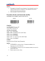
1
Handheld Scanner
- MS839L -
User’s Manual
Version 1.1
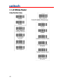
Table of Contents
Chapter 1
Overview ..........................................................................................................1
Introducing the MS839 ............................................................................1
Chapter 2
Keyboard Interface...........................................................................................3
Installation ...............................................................................................3
Installation without keyboard or laptop computer.....................................4
Installed as an USB Interface ..................................................................5
Operating Parameters .............................................................................5
Chapter 3
RS232 Serial Interface.....................................................................................7
Installation ...............................................................................................7
Operating Parameters .............................................................................8
Serial TTL ................................................................................................9
Chapter 4
Terminal Interface .......................................................................................... 11
Installation ............................................................................................. 11
Operating Parameters ...........................................................................12
Chapter 5
Setup .............................................................................................................13
Barcode Menu Setup.............................................................................13
i
Setup Procedures .........................................................................13
Barcode Length Setting.................................................................14
Code ID Setting.............................................................................15
Preamble (Prefix) and PostambIe (Suffix) .....................................16
Quick Setup...........................................................................................17
Batch Setup...........................................................................................17
Scanner Configuration Manager Software.............................................19
Factory Default Setting ..........................................................................20
Chapter 6
Pin Assignment ..............................................................................................21
TTL, Wand Emulation ............................................................................21
Keyboard Interface ................................................................................21
RS232 Interface ....................................................................................22
Appendix A
Examples .......................................................................................................23
Quick Setup Sheet.................................................................................23
Function Codes .....................................................................................26
Function Codes for PC..................................................................26
Setup Menu ...........................................................................................28
Device Selection and Default: Group 1 .........................................28
Beeps and Delays Group 2 ...........................................................29
Keyboard Wedge Settings Group 3...............................................31
RS232 Settings Group 4 ...............................................................34
Scanner Port: Group 5 ..................................................................35
Define Code ID Group 5................................................................37
ii
Code 39 Group 6 ..........................................................................38
I 2 of 5 Group 6 .............................................................................39
EAN 128 Group 6..........................................................................41
Code 128/Code 93/MSI Code Group 7 .........................................42
Code 11/Codaber Group 7 ............................................................43
UPC/EAN Code Group 8...............................................................44
Supplement Code Group 8 ...........................................................46
Dump Setup Strings Group 9 ........................................................46
DataBar (RSS), Limited, Expanded Group 10...............................47
Full ASCII Chart.....................................................................................49
Barcode Chart .......................................................................................56
Appendix B
Worldwide Support.........................................................................................57
iii
iv
Chapter 1
Overview
Introducing the MS839
As a keyboard scanner supports most of the popular PCs and IBM terminals.
As a RS232 serial scanner sends data by using RS232 communication protocol.
The communication speed (baud rate) ranges from 300 bps to 38400bps.
As a RS232 terminal interface, systems with ANSI ASCII communication
environment such as UNIX, XENIX are installed between a host computer and
a terminal and supports full duplex and block communication modes.
As a wand emulation scanner, the output of the scanner emulates a wand
scanner output. Two output formats are supported. Code 39 format and Native
Code 39 format, the scanner always outputs the same data contents but with
Code 39 what symbology. Native scanner the same contents and symbology
as the scanned label.
The scanner supports the following bar code symbologies:
Code 39 Standard and Full ASCII UPC/EA.N with supplement codes Interleaved 2 of 5
Standard 2 of 5
MSI code
Plessey code
Codahar
UCC/EAN128
Code 32 (Italian pharmacy)
Code 93
Code 128
China Postal Code
(Toshiba Code)
1
2
Chapter 2
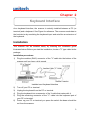
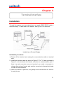
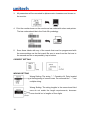
Keyboard Interface
As a keyboard Interface, the scanner is actually installed between a PC (or
terminal) and a keyboard. See Figure for reference. The scanner sends data to
the host device by emulating the keyboard input and acts like an extension of
the keyboard.
Installation
This scanner can be installed easily by following the installation guide
illustrated below. Before you start the installation, locate a "Y" type cable in the
package.
Installation procedures:
1) Plug the modular (RJ45) connector of the "Y" cable into the bottom of the
scanner until you hear a click sound.
Installed as a Keyboard Interface
2)
3)
4)
5)
Turn off your PC or terminal.
Unplug the keyboard from the PC or terminal.
Plug the keyboard into a connector of the Y cable that mates with it.
Plug the remaining connector of the "Y" cable into the keyboard port of
6)
your PC or terminal.
Power up your PC or terminal you press the switch the beam should be
out from the scanner.
3
7)
8)
9)
If nothing happens at step 6, check all cable connections first and
make sure your PC or terminal has been powered. Contact
technical support if.
Unless the scanner has been prior installed for the PC/terminal, user may
have to select a proper device number from Group 1 of Appendix D.
The Default setting of this scanner is IBM PC/AT and PS/2. If you like
to make sure that you have the right selection, you may scan the
following label.
Installation without keyboard or laptop computer
The scanner has the capability to answer the keyboard inquiry made
by PC to avoid " Keyboard Error " message when keyboard is not present.
This implementation is useful to the applications where keyboard
entry is not necessary. You may scan the following label to enable
this feature. (Some of the l a p t op c om p ut e r s m a y n ot w o r k
p r o p e r l y w i t h t h i s feature. Please contact your local vendor for
further support.)
4
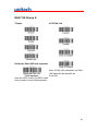
Installed as an USB Interface
You can install the scanner with the USB interface cable to work with either PC
or iMac USB port. See Figure 1.1 for reference. Your operating system may
require the original setup CD to install the driver with initial setup.
Installed as an USB Interface
The factory default setting should work with either PC or iMac USB interface; you may
also scan the following label to make sure you get the right device setting.
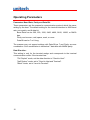
Operating Parameters
There are some operating parameters that can be configured to work for
different applications.
Intercharacter Delay
Intercharacter delay is the time period that the scanner will wait before
transmitting the next character after the first character was sent. If data sent by
the scanner was incorrect or missing characters, a longer intercharacter
delay may solve the problem.
Interblock Delay
lnterblock delay is the minimum time interval between two adjacent scanning.
If the processing speed of your host device is slower than your scanning
speed, a longer interbIock delay may ensure the data integrity.
5
Function Code
The scanner can emulate function and other special keys on the keyboard by
scanning some pre-defined labels. Appendix B includes those labels for
special keys on PC, Macintosh, and IBM terminals. As an option, you may also
print these labels by printing their corresponding Code 39 characters (in
brackets) to work with scanner.
Caps-Lock
This parameter tells the scanner the current Caps-Lock status of the keyboard
so that the character transmitted by the scanner is in correct case.
Auto Trace (For PC AT/XT only):
In Auto Trace mode, the scanner will keep track of the Caps-Lock status
automatically. For some PCs, the scanning performance may he
compromised because of the auto tracing. If the scanning performance is
poor (or can not scan), or the scanner cannot output the upper/lower case
characters correctly, try to select one of the next two choices instead of
auto tracing.
Lower Case:
When the keyboard is in the unshifted state (Cap Lock is not pressed),
select "Lower Case".
Upper Case:
When keyboard has the CapLock key on, select "Upper Case".
Alt Key Mode
"ALT Key Mode" is a choice in the language selection. Sending characters by
ALT key plus keys on the numeric keypad is a feature in MS-DOS. When
selecting "ALT Key Mode", the scanner sends out the native ASCII
combination codes to represent each character of the bar code scanned. If
your system accepts ALT key sending, you can enable this mode and ignore
selections of the "Upper/Lower Case" and "Language".
You may find these settings on the Appendix D page D2 and D3.
6
Chapter 3
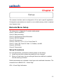
RS232 Serial Interface
Installation
To use the scanner as a RS232 serial interface, a RS232 interface cable and
a power adapter are required. See chapter 1 for cable pinout and
adapter specification. Figure 2 shows an installation diagram for your
reference.
Installation procedures:
1) Make sure the scanner's cable has the right connector and pinout for the
RS232 port of the host device. If the pinout is different from device,
swapping pins is necessary to achieve proper communication.
2) If the host device has power output at RS232 interface port, the scanner
can be powered by connecting that power line to pin 9 of the scanner
connector. If there is no power at RS232 port, adapter is needed Plug the
adapter into the DB type connector at the end of the interface cable.
Installed as a Serial Interface
3) Plug the DB type connector the interface cable into host's RS232 port and
power up the device.
4) When the scanner is powered, a long beep sound indicates the scanner is
ready to use.
7
Operating Parameters
Device Type
Baud Rate, Parity and Data Bit:
These parameters set the scanner's communication protocol that must be
matched by the host. The default setting for the serial interface is 9600 baud rate,
none parity, and 8 data bit.
Baud Rate can be 300, 600, 1200, 2400, 4800, 9600, 19200, or 38400
bps.
Parity can be even, odd, space, mark, or none.
Data Bit can be 7 or 8 long.
The scanner may not support settings with Data Bit as 7 and Parity as none
combination. Such combination is treated as 7 data bits with MARK parity.
Handshaking:
The scanner supports CTS/RTS handshaking as an option. The hardware
handshaking is supported on character-by-character basis.
During the communication, the scanner will stop sending data until the CTS is
valid within time specified by the Time Out parameter. During this time-out
waiting period:
If CTS is valid.
If CTS is not valid, the scanner sounds an error beep and discards the
current buffered data.
BCC Character:
BCC check character is calculated for entire data stream by using "Exclusive
OR" method. it is sent after data stream for data verification.
Time Out:
You can adjust the Time Out duration for handshaking and ACK/NAK protocol
to fit applications.
8
Serial TTL
This scanner supports serial TTL interface, which follows the RS232
communication data format but with TTL voltage output ranged from OV to
5V.
9
10
Chapter 4
Terminal Interface
Installation
To install the scanner as a terminal interface, you need a DB25 RS232 cable, a
terminal wedge "Y" cable and an AC adapter. See Figure 3 for reference.
Installed as a Terminal Wedge
Installation procedures:
1) Power off the terminal and unplug the communication cable at terminal
side.
2) Install the interface cable as shown in Figure 3. The "Y" cable provided in
Figure 3 is for terminals with female connector on communication port. If
there is a male connector on your terminal, you need a converter to
change that male to female and another converter to change the female
to male on host connector.
3) When the scanner is powered, a long beep sound indicates that the scanner
is ready to use.
11
Operating Parameters
Parameters Baud Rate, Parity and Data Bit:
These parameters set the scanner's communication protocol which the same
setting by the host. The default setting for the terminal interface is 9600 baud
rate, none parity, and 8 data bit.
Baud Rate can be 300, 600, 1200, 2400, 4800, 9600, 19200, or 38400
bps.
Parity can be even, odd, space, mark, or none.
Data Bit can be 7 or 8 long.
The scanner may not support settings with Data Bit as 7 and Parity as none
combination. Such combination is treated as 7 data bits with MARK parity.
Data Direction:
This setting is only for the terminal wedge and corresponds to the terminal
communication mode. If the terminal has:
12
"Full Duplex" mode, set the data direction to "Send to Host".
"Half Duplex" mode, set to "Send to Host and Terminal".
"Block" mode, set to "send to Terminal".
Chapter 5
Setup
The scanner interface can be configured to fit the user's specific application.
Configuration parameters are stored in a non-volatile memory, which is retained
even if power is lost.
Barcode Menu Setup
The setup menu in Appendix C contains eight groups:
Group 1: Device selection.
Group 2: Beep and delay.
Group 3: Keyboard and Wand Emulation.
Group 4: RS-232 Settings.
Group 5: Scanner port.
Group 6: Code 39,1 2 of 5, S 2 of 5 and Code 32.
Group 7: Code 128, Code 93, Code 11, Codabar, and MS.
Group 8: UPC/EAN
Group 9: Dump setup
Setup Procedures
For most parameters, proceed the following steps for the setting:
1) Locate a group that contains the parameter to be changed.
2) When you hear beep, the new setting will have been defined or updated
into the memory processor.
Default parameters are indicated in bold type and underlined characters. The
character font is BLACK.CD = Check Digit.
CDV = Check Digit Verification.
13
Most settings require only a single bar code, but a few need several different bar
codes to be scanned in order to completely define a setting. They are:
Double Verification:
Step 1: Scan Double Verification from Group 5
Step 2: Scan one digit
Step 3: Scan Double Verification
Min Length / Max Length
Step 1: Scan MIN LENGTH or MAX LENGTH.
Step 2: Scan two digits from Appendix E.
Step 3: Scan MIN LENGTH or MAX LENGTH.
NOTES:
1. If you hear three times of beeps, please re-operate.
2. If you operate improperly, reset the scanner and re-scan.
Barcode Length Setting
The following example illustrates how to set Code 39 with a minimum length
of 5 and a maximum length of 20:
Scan "Enter Group 7"
Scan "Fl" to select Code 39
Scan "MIN LENGTH" to enter minimum length setting
Scan "0 " and "5" to select length 5. (Appendix E)
Scan -MIN LENGTH" to end minimum length setting
Scan "MAX LENGTH" to enter maximum length setting
Scan "2" and "0" to select length 20. (Appendix E)
Scan "MAX LENGTH" to end maximum Length Setting
Scan "Exit" to end setup
14
Code ID Setting
Each bar code symbology supported by the scanner has a default ID character
defined as below.
CODE ID IDENTIFIER
SYMBOLOGIES
Factory ID
SYMBOLOGIES ID
Factory ID
MSI
O
CODABAR
N
EAN 8
E0
UPC-E
E
UPC-A
A
UK PLESSY
P
EAN 13
F
Code 93
L
FULL ASCII Code 39
M
Code 11
J
STANDARD Code 39
M
TELEPEN
J
S25 Code
TT
EAN 128
FF
INDUSTRIAL 2 OF 5
H
(Code 2 of 5)
Code 128
K
China Post Code
C
(Toshiba Code)
Code 32
(Code 39 PARAF)
T
INTERLEAVED 2OF 5
T
SET ID - SETTING PROCEDURES
Setting steps:
1. Scan the SET ID bar code for a particular symbology
2. Scan one or two alphanumeric characters from the Full ASCII Table.
Scan the SET ID bar code again.
Example: Define the MSI Code ID = A, Code 93 = G9
MSI:
Step 1: Scan MSI Set ID (Group 5).
Step2: "A"
Step3: Scan MSI Set ID (Group 5).
Code 93:
Step 1: Scan Code 93 Set ID (Group 5).
Step2: "G" from "A" Appendix E. Full ASCII Chart, Scan "9" from "A" Appendix
E. Full ASCII Chart.
Step3: Scan Code 93 Set ID (Group 5).
15
NOTES:
1. The length of a Code ID is one character. If one character is set, the
Code ID output will be one character. If two characters are set, the
Code ID output will be two characters.
2. Only one type of Code ID will be sent.
Preamble (Prefix) and PostambIe (Suffix)
PREAMBLE & POSTAMBLE (PREFIX AND SUFFIX)
.A012$
PREAMBLE (16)
.A013$
POSTAMBLE (16)
EXAMPLE:
Set PREAMBLE String as " ## "
POSTAMBLE String as "$$"
SETTING PROCEDURE
STEP 1: Scan: PREAMBLE.
STEP 2: Scan: "4" twice from FULL ASCII Table.
STEP 3: Scan: PREAMBLE.
STEP 4: Scan: POSTAMBLE.
STEP 5: Scan: " $ " twice From FULL ASCII Table.
STEP 6: Scan: POSTAMBLE.
FORMAT
{Preamble} {Code ID} {Bar Code} {Postamble}
NOTES:
1. A PREAMBLE is a string of up to 16 characters added to the
beginning of a scanned barcode.
2. A POSTAMBLE is a string of up to 16 characters added to the end of a
scanned bar code.
3. Default value for either: None.
16
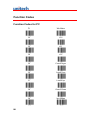
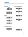
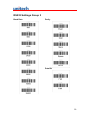
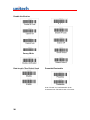
Quick Setup
Appendix A has a quick setup chart, which gives you one label or one
function convenience to the scanner. To setup the scanner, locate the label
with the function you want and scan that label.
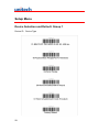
Batch Setup
If you need to configure more than one scanner, you may duplicate the settings
of the scanner (master) to the others. You can do this by producing a set of
custom setup labels derived from the master scanner and scanning these
labels configuring the other scanners.
The following label is called "Dump Settings" label. Before you scan the label,
please open a text editor application (such like, Notepad, Word, etc.)
Scan the following label, the settings of the scanner will dump to the screen
as one or several ASCII string(s). Use any barcode printing software, select 39
symbology, and use the string(s) to generate bar code labels. You use this
batch setup labels to duplicate setting to the other scanners.
Dump Settings
EXAMPLE:
1. PR OJECT ASSIGNMENTS:
1.1 Beep tone: BEEP LOW – HIGH
1.2 Capslock Mode: CAPSLOCK ON (FIXED)
1.3 Reading Mode: CONTINUOUS AUTO OFF
2.
SETTING PROCEDURE:
2.1 Scan BEEP LOW. - -HIGH (GROUP 3)
2.2 Scan CAPSLOCK ON (FIXED) (GROUP 3)
2.3 Scan CONTINUOUS AUTO OFF (GROUP 2)
17
3.
All parameters will be converted to alphanumeric characters and shown on
the monitor.
4. Print the results shown on the monitor as bar codes with a bar code printer.
The bar codes should be in the Code 39 symbology.
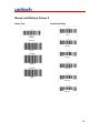
5.
Scan these labels with any of the wands that must be programmed with
the same settings as the first wand. Be sure to scan from the first row to
the second and so on sequentially, top to bottom.
CORRECT SETTING
WRONG SETTING
Wrong Setting: The string "...." Consists of 4 Dots, located
at the beginning of second rows. Do not break the "...." Into
multiple string.
Wrong Setting: The string lengths in the second and third
rows do not match the length requirements, because
rows should be in lengths of four digits.
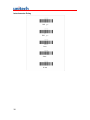
18
Wrong Setting Because you add “...” After .A0 17$
The 0.A17$ is a FIXED parameter for setup entering. It is
an unchangeable parameter. Never add, delete or
rearrange data from the FIRST row.
Only the settings that are different from the default values will be dumped.
The settings can be dumped to a PC or terminal only if that PC or terminal
matches the type defined by Device Type of the scanner. The previous
example of "Keyboardless Wedge" as Device Type is equivalent-to a
PC/AT interface, so you cannot dump that settings to a system which dose
not support a PC/AT keyboard interface.
The following label dumps the settings to a PC/AT regardless what kind of
device has been chosen on the scanner.
Dump Settings On PC/AT
You can adjust the length of the dumped strings by combining multiple
strings into one or breaking one string into multiple strings. The following
strings have the same effect as the dumped string listed above:
...1800C06D51DJ8080
80A007C005354415254.
You cannot delete any character from or add any character into the strings and
the first three characters ("...") must be present in the first string.
All characters in dumped strings are in upper case. If you see lowercase
characters in dumped strings, change them to upper case.
Scanner Configuration Manager Software
Scanner Configuration Manager is a utility program to users to configure
scanner settings on a computer using the Microsoft Windows based
operating system. Use this program to define the settings and then
download the parameters to the scanner.
19
Factory Default Setting
To clear all the setting data, please scan the factory default barcode.
20
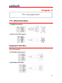
Chapter 6
Pin Assignment
TTL, Wand Emulation
1.1) AMP (D-Sub 9Pin):
1.2) Din 5 male (240 degree)
Keyboard Interface
Type of Connector
2.1) PS/2 Mini Din6 Female
2.2) PS/2 Mini Din6 Male
21
2.3) PC-AT: Din5 Male
2.4) PC-AT: Din5 Female
RS232 Interface
3.1) DB9F
3.2) DB25F
22
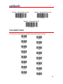
Appendix A
Examples
Quick Setup Sheet
Device Type
Scanner Mode
PCAT[PS/2]/USB
Trigger
Keyboardless
Flash
Code39 Wand Emulation
CONTINUOUS MODE
Serial Interface
CONTINUOUS AUTO OFF
Beep
UPC-E
Cut Leading Digit
Send Check Digit
None
Terminator
Enter
UPC-A Conversion
23
Scan Code
U.S.
UPC-E Expand to UPC-A
Enable
Alt Key
EAN-8
Cut Leading Digit
Disable
UPC-E Expand to E EAN 13
Enable
Cut Check Digit
EAN-13
Disable
Note:
Cut Leading Digit
1. If UPC E Expand To UPC Format is
enabled, the output of UPC-A is 12 digits.
2. The default output of UPC-A is 12 digits,
and if UPC E Expand To EAN13 is enabled,
Cut Check Digit
a zero will be added in front of the barcode.
Code ID
No
ISBN Conversion
Yes
Character Delay
140μs
4ms
24
UPC-A
Cut Leading Digit
Cut Check Digit
Supplement Code
No
Yes
Setup
Enable
Disable
Display Version
Factory Default
25
Function Codes
Function Codes for PC
26
F1
Win Make
F2
F10
F3
F11
F4
F12
F5
Cursor Right
F6
Cursor Left
F7
Cursor Up
F8
Cursor Down
F9
Win Break
Home
Ins
End
Alt Make
Pg Up
Alt Break
Pg Dn
Left Shift Make
Tab
Left Shift Break
Back Tab
Left Ctrl Make
ESC
Left Ctrl Break
Enter
Return
Del
27
Setup Menu
Device Selection and Default: Group 1
Device ID
28
Device Type
Beeps and Delays Group 2
Beep Tone
Interblock Delay
1 ms
.F022$
10 ms
Low
.F018$
50 ms
Mediu
.F019$
100 ms
High
200 ms
500 ms
29
Intercharacter Delay
140 μs
500 μs
1 ms
4 ms
16 ms
30
Keyboard Wedge Settings Group 3
Function Code
Level Duration of Mini Width
.B016$
Off
.B015$
ON
Polarity of Idle Condition
Caps-Lock
Output of Wand Emulation
31
Language (For PC/XT, AT)
Use number Keypad digits
32
RS232 Settings Group 3
Baud Rate
Parity
Data Bit
33
RS232 Settings Group 4
Handshaking (for serial wedge)
BCC Character (for serial wedge)
On
Off
Time Out (for serial wedge)
ACK/NAK (for serial wedge)
34
Scanner Port: Group 5
Terminator
Scanning Mode
Flashing wait 60 sec.
Code ID
Note:
This setting doesn't affect EAN128 code ID.
EAN128 has its own Code ID setting on
page 33.
Label Type
35
Double Verification
Factory Default
Factory ID On
Data length (Two Digits) Send
Preamble/Postamble
Scan “PP/OO” for Pre/Postamble. Scan
characters from Full ASCII char or Function.
36
Define Code ID Group 5
Define Code ID
37
Code 39 Group 6
Code 39
Define Code ID
Full ASCII Code 39 Enable
38
Full ASCII Code 39 Disable
I 2 of 5 Group 6
I 2 of 5 (ITF)
39
S 2 of 5/China Postal
Code (Toshiba Code)
Code 32 (Italian Pharmacy)
40
EAN 128 Group 6
Telepen
UCC/EAN 128
Define the EAN 128Fields separator
Scan an ASCII code in full ASCII code
chart to select a new fields separator.
Note: If EAN 128 is disabled, the EAN
128 labels will be decoded as
Code128.
41
Code 128/Code 93/MSI Code Group 7
Code 128
Code 93
42
MSI/Plessey Code
Code 11/Codaber Group 7
Code 11
Codabar
43
UPC/EAN Code Group 8
UPC-A
UPC-E
44
UPC/EAN Code Group 8
EAN-13
EAN-8
45
Supplement Code Group 8
Supplement Code
See the Batch Setup section for using the labels below.
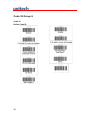
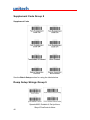
Dump Setup Strings Group 9
Speed=9600, Databit=8, Parity=None,
Stop=1FlowControl=None
46
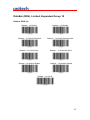
DataBar (RSS), Limited, Expanded Group 10
Databar (RSS-14)
Databar – 14 Disable
Databar – 14 Enable
Databar – 14 Check Digit Send
Databar – 14 Prefix Send
Databar – 14 Stacked Enable
Databar – 14 Check Digit Not Send
Databar – 14 Prefix Not Send
Databar – 14 Stacked Disable
Databar – 14 Set ID
47
Databar (RSS LIMITED)
Databar – Limited Enable
Databar – Limited Disable
Databar – Limited Check Digit Send
Databar – Limited Check Digit Not Send
Databar – Limited Prefix Send
Databar – Limited Prefix Not Send
Databar – Limited Set ID
Databar (RSS-EXPANDED)
Databar – Expanded Enable
Databar – Expanded Stacked Enable
48
Databar – Expanded Disable
Databar – Expanded Stacked Disable
Databar – Expanded Min Length
Databar – Expanded Max Length
Databar – Expanded Set ID
Full ASCII Chart
(Characters in parentheses represent Code 39 barcode printing)
49
50
51
52
53
54
55
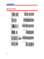
Barcode Chart
56
Appendix B
Worldwide Support
Unitech’s professional support team is available to quickly answer questions or
technical-related issues. Should an equipment problem occur, please contact
the nearest Unitech regional service representative. For complete contact
information please visit the Web sites listed below:
Web Site
Region
Global Operation Center
www.unitech-adc.com
Unitech Asia Pacific & Middle East
www.unitech-utp.com.tw
Greater China Division
www.unitech-sbd.com
Unitech Japan
www.unitech-japan.co.jp
Unitech America
www.ute.com
Unitech Latin America
www.latin.ute.com
Unitech Europe
www.unitech-europe.nl
57
58