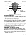
1
i-on40 & i-onEX Range © Cooper Security Ltd. 2012 IN NO EVENT WILL COOPER BE LIABLE FOR ANY SPECIAL, CONSEQUENTIAL , OR INDIRECT LOSS OR DAMAGE, INCIDENTAL DAMAGES, STATUTORY DAMAGES, EXEMPLARY DAMAGES, LOSS OF PROFITS, LOSS OF REVENUE, LOSS OF ANTICIPATED SAVINGS, LOSS OF BUSINESS OR OPPORTUNTIY, LOSS OF GOODWILL OR INJURY TO REPUTATION, LIQUIDATED DAMAGES OR LOSS OF USE, EVEN IF INFORMED OF THE POSSIBILITY OF SUCH DAMAGES. COOPER‟S LIABILITY FOR DAMAGES ARISING OUT OF OR RELATED TO A PRODUCT SHALL IN NO CASE EXCEED THE PURCHASE PRICE OF THE PRODUCT FROM WHICH THE CLAIM ARISES. TO THE EXTENT PERMITTED BY APPLICABLE LAW, THESE LIMITATIONS AND EXCLUSIONS WILL APPLY WHETHER COOPER‟S LIABILITY ARISES FROM BREACH OF CONTRACT, BREACH OF WARRANTY, TORT (INCLUDING BUT NOT LIMITED TO NEGLIGENCE), STRICT LIABILITY, BY OPERATION OF LAW, OR OTHERWISE. Every effort has been made to ensure that the contents of this book are correct. The contents of this book are subject to change without notice. Printed and published in the U.K Part Number 12172413 31/1/12 Warning: Mains voltages are present inside control unit. No user serviceable parts inside. Page ii i-on40 & i-onEX Range Contents 1. Introduction ..................................................................... 1 Setting and Unsetting ........................................................... 3 Alarms and Reset ......................................................................... 3 Security Levels ............................................................................ 4 Partitions .................................................................................... 4 24 Hour Alarms ............................................................................ 4 Communications .................................................................. 5 Security Grade..................................................................... 5 Controls and Displays ........................................................... 6 Controls: ..................................................................................... 6 Displays ...................................................................................... 7 Users.................................................................................. 8 Types of User .............................................................................. 8 Identifying Users ........................................................................ 10 Access to the System .......................................................... 10 Access Codes ............................................................................. 10 Proximity Tags ........................................................................... 11 Remote Controls ........................................................................ 12 TwoWay Key Fob........................................................................ 12 Radio Hold Up Alarms (HUA)........................................................ 13 2. Alarms ............................................................................ 15 Silencing an Alarm .............................................................. 15 If You Cannot Reset the System ................................................... 17 Accidental Alarms................................................................ 18 Speech Messages ................................................................ 18 Acknowledging a Speech Message ................................................ 19 Alerts (or Why is it Beeping?) ............................................... 19 Technical Alarms ........................................................................ 20 3. Setting and Unsetting ..................................................... 22 Setting and Unsetting With a Keypad ..................................... 22 Setting ..................................................................................... 23 If the System Will Not Set ........................................................... 29 Other Reasons Why the System May Not Set ................................. 30 Unsetting the System Using a Keypad........................................... 31 Using Radio Keypads and Remote Controls. ............................ 33 Using a Radio Keypad ................................................................. 33 Using a Remote Control .............................................................. 34 Using a Two-Way Key Fob ........................................................... 35 4. Administration ................................................................ 38 Entering and Leaving the Menu ............................................. 38 Editing Text ........................................................................ 39 Omitting Zones ................................................................... 40 Users................................................................................. 41 Editing Existing Users ................................................................. 42 Adding Users ............................................................................. 56 Deleting Users ........................................................................... 59 Page iii i-on40 & i-onEX Range Viewing the Log .................................................................. 61 Testing the System ............................................................. 62 Sirens & Sounders...................................................................... 62 Keypad ..................................................................................... 65 Walk test .................................................................................. 66 Outputs .................................................................................... 69 Remotes and Two-way Keyfobs ................................................... 70 Radio Hold Up Alarms ................................................................. 72 Proximity Tags........................................................................... 74 System Configuration .......................................................... 75 Switching the Chime On/Off ........................................................ 75 Allowing Remote Access .............................................................. 76 Setting the Date and Time .......................................................... 78 Calendar Set ............................................................................. 79 Programming Outputs ................................................................ 89 Programming Remote Controls and Fob-2W-4B for Users ................ 95 Deleting Remote Controls.......................................................... 102 Preventing Any Remote From Unsetting the System ..................... 105 Allowing Fob-2W-4B or 727r to start a HUA ................................. 106 Starting a Call To Downloader ................................................... 107 Redirecting Speech Messages .................................................... 109 Turning Outputs On/Off ..................................................... 110 What System Have I Got? .................................................. 112 Seeing Which Communications Module Is Currently Installed: ....... 112 List of Menu Options ......................................................... 114 Alarm Functions At a Glance ..............................................115 Setting and Unsetting ........................................................ 115 After an Alarm .................................................................. 116 To Start a HUA from the Keypad ......................................... 116 Page iv i-on40 & i-onEX Range Compliance Statement The i-on50EX and i-on160EX: Are suitable for use in systems designed to comply with PD6662:2010 at Grade 2, Grade 3 and environmental class II. Are suitable for use in systems designed to comply with the requirements of EN50131-3 at Grade 2, Grade3 and environmental class II. Comply with the requirements of EN50131-6:2008 at Grade 2, Grade 3 and environmental class II. The i-on30EX and i-on40: Are suitable for use in systems designed to comply with PD6662:2010 at Grade 2, and environmental class II. Are suitable for use in systems designed to comply with the requirements of EN50131-3 at Grade 2 and environmental class II. Comply with the requirements of EN50131-6:2008 at Grade 2 and environmental class II. When fitted with the appropriate communicator these products are compliant with EN 50136-1. They allow the alarm transmission system to meet the performance requirements of EN 50131-1:2006 ATS 2 provided that: a) They are installed in accordance with the installation instructions. b) The connected PSTN is functioning normally. If the installer selects a non-compliant configuration then they must remove or adjust compliance labelling Please Note: This Guide applies to i-on control units with version 4.00 software. Page v i-on40 & i-onEX Range This page is intentionally blank. Page vi i-on40 & i-onEX Range 1. Introduction At the heart of the i-on range systems are the control units, their expanders and keypads. The control unit contains the main processing unit, the power supply and stand-by battery. The stand-by battery can keep the alarm system going for several hours if the mains supply fails. Connected to the control unit by cable are the keypads and, where applicable, expanders. The expanders provide extra connection points for detectors, either wired or radio. The keypads each have a two line display to show you status information, and various keys for operating the system. The keypads also contain a speaker to give warning tones when the system is setting or unsetting. Users identify themselves to the system by keying in access codes at the keypads. If they do not wish to use access codes then some types of keypad also contain proximity tag readers, allowing users to identify themselves by means of small electronic tags that they carry with them. In addition to and access code or proximity tag, each user can be assigned one portable four-button remote control and/or one twobutton hold up alarm. To protect an area the control unit can operate a range of detectors. Detectors can be connected to the control unit or expanders by wires, or communicate to a radio expander using a small radio transmitter. Figure 1 shows some examples. In addition to fixed detectors the control unit can also monitor small portable transmitters that users can employ to start alarms remotely, for example in the case of a Hold Up Alarm. (Hold Up Alarm (HUA) is also known as Panic Alarm or PA.) When the control unit detects an alarm, it can start an external sounder/strobe unit by sending the appropriate radio signal. In addition the control unit can also communicate using a variety of plug on modules. Some modules also provides speech recording and playback facilities so that the system can send recorded speech messages to pre-programmed telephone numbers. Page 1 1. Introduction i-on40 & i-onEX Range The control unit and expanders also provide sets of connectors for outputs, which the installer can use to link the control unit to siren/strobe units or other equipment. 1 2 3 A B 1. Two button Hold Up Alarm with tilt switch. 4 2. Two button Hold Up Alarm. 5 6 3. Four button remote control. 4. Keypad. 5. Two-way remote control. 6. Wireless arming station. 7. Door Contact/Universal Transmitter. 7 8 8. Smoke Detector. 9. Passive Infra Red. 10. External siren/strobe. 10 Figure 1. Peripherals Page 2 9 i-on40 & i-onEX Range 1. Introduction This guide covers four types of i-on control unit: the i-on30EX, ion40, i-on50EX and the i-on160EX. A complete system using one of these control units comprises: Control unit i-on30EX Fixed detectors 30 External Siren/Strobe 4 Users 50 Portable 4-button 50 remote controls (one per user) Portable two-button 50 hold up alarms (one per user) i-on40 40 4 50 50 50 i-on50EX i-on160EX 50 160 5 20 100 500 100 500 100 500 To find out which system you have see page “What System Have I Got?” on page 112. Setting and Unsetting The majority of alarm systems are intended to detect the movements of people, and to notify others when people move into protected areas. Readying the system to start an alarm when someone moves into a protected area is called “setting” the system. Disarming the system so that people can move freely is called “unsetting” the system. Alarms and Reset When the system starts an alarm it usually includes activating sounders and strobes and sending messages to an Alarm Receiving Centre (ARC). The ARC may then call the police or other security service to come and investigate the alarm. Before you can set the system again you must silence the sounders and then “reset” the system so that it is ready for setting again (see page 15 for instructions). Please note that your Installer may have programmed your system so that although you can silence the sounders, you cannot reset the system yourself. Instead you have to call the Installer to come and check the system and reset it for you. Page 3 1. Introduction i-on40 & i-onEX Range Security Levels At a site where all users have complete access to the whole site, then the installer can program the control unit to provide four levels of security: Full Set and three different Part Sets. Any user can put the alarm system into any of the security levels. Each security level is a collection of one or more detectors that monitors a different area. The highest security level is called Full Set, and includes all the detectors. There are three other security levels called Part Set B, C and D. For example, in a small shop Full Set might monitor the whole premises, while Part Set B might monitor just the store room. Any rear doors would normally be monitored 24 hours a day (see “24 Hour Alarms” below). Partitions If the system is installed at a site where some users must be restricted to parts of the site, for example a warehouse with storage areas and separate offices, then the installer can split the system electronically into separate “partitions”. The i-on160EX can have up to 20 partitions, the i-on50EX up to five, the i-on30EX and i-on40 up to four. Users can set and unset each partition completely independently of all the others. Individual users can be given access to one or more partitions: if they have no access to a partition then they cannot set or unset that partition. In effect the system splits into 20 (or five, or four) separate alarm systems. In addition each partition can be programmed to set at one of two security levels: either Full Set or Part Set. Any user who is allowed to set a partition can select either of the two security levels. 24 Hour Alarms The control unit can also monitor detectors continuously rather than being set and unset. For example: Fire and smoke detectors, flood sensors, Hold Up Alarm buttons or emergency exits. Monitors for machinery (for example freezers) or other type of “technical alarm”. Page 4 i-on40 & i-onEX Range 1. Introduction These are collectively known as “24-hour alarms” because they can cause an alarm 24 hours a day: it does not matter whether a user has set or unset the system. Communications Your system may be fitted with a communication module that allows the control unit to send alarm information over the telephone network, the mobile phone network, or the internet. There are separate modules for each of these different tasks. The Installer may also be able to call into your control unit and program it remotely. Depending on how your Installer has programmed the system you may receive a phone call from them requesting you to give them access to your alarm system. Security Grade For insurance purposes there are several different “Grades” of security system. Your system may be either Grade 2 or Grade 3. Ask your installer which Grade you have since a Grade 3 system operates slightly differently from a Grade 2 system. Note that the i-on30 and i-on40 can only be configured as Grade 2 systems. Page 5 1. Introduction i-on40 & i-onEX Range Controls and Displays Figure 2 shows the controls and displays available on the keypads. 1 2 7 3 4 6 5 1. LCD display . 2. Programming keys. Also used to gain access to programming menus and acknowledge alerts. 3. Navigation key 4. Setting and unsetting keys. These can be programmed to either set/unset the system or operate output. 5. Hold Up Alarm (HUA) keys. (Also knows as PA keys.) 6. Alpha/numeric keys. 7. Set/Unset status LEDs (not used in partitioned systems). Figure 2. Controls and Displays Controls: A Full Sets the system. (All detectors in use.) In a partitioned system this key‟s function can be programmed by the installer. B, C Part Set the system. (Some of the detectors in use.) In a and D partitioned system their function can be programmed by the installer. Unsets the system. In menus: scroll up. In text editing: move cursor left In menus: scroll down. In text editing: move cursor right. If the bottom line of the display shows a “>” at the right then pressing this key selects the submenu named on that line. Page 6 i-on40 & i-onEX Range 1. Introduction If the bottom line of the display shows “On” “Off” “Yes” “No” “I” (for include) “O” (for omit) then pressing this key changes the value to its opposite. When editing names moves the cursor to the right. Deletes characters when editing names. Press this key to confirm a decision and save any changes. a) Moves the display to a higher level of the menu. b) Press this key to abandon your decision when the display shows “Are you sure Y/N?” Press this key to gain access to the Menu. 1 to 0, Used to key in access codes. Also used to key in text for *, # names, and telephone numbers. # Used when keying in text: press to change between capitals or small letters. Press both these keys at the same time to start a Hold Up Alarm. (The Installer must enable this feature.) Displays The LCD display shows messages and prompts to help guide you through setting, unsetting, resetting and programming the system. When the system is idle (either while set or unset) the display shows the “standby screen”, comprising the time and date: (The top line of the display may show the installer‟s name instead of “ion160”.) To draw your attention to special events the rim of the navigation key glows red. Page 7 1. Introduction i-on40 & i-onEX Range In a part setting system, the four LEDs on the right of the programming keys show you whether the system is set or unset: The left hand LED glows when the system is full set, the other LEDs glow when the system is in one of the part set states. In a partitioned system these LEDs are not used. Note that the installer can disable these LEDs in order to hide the state of the system (to comply with EN50131). In addition, in a Security Grade 2 installation the installer may have programmed the LEDs to glow for 30s immediately after setting, and then to go out. Detectors or Zones? When talking about alarm systems, people tend to use the words “detectors” and “zones” interchangeably. Most of the time this doesn‟t matter, but occasionally it can cause some confusion. In this book a “detector” is a physical piece of equipment that signals some event. A “zone” is how the keypad reports the location of the detector. The reason for this is that an installer may connect several detectors together to guard one “zone” (an area of a building for example). The control unit cannot tell that this has happened, so it is easier for the keypad to report an alarm from a “zone”. Most of the time there is only one detector per zone, especially with radio detectors. Users Types of User The control unit provides for seven different types of user: Master User This user can add any other user to the system, edit them, or remove them. There is always (at least) one master user: User 001 (User 01 on i-on30EX and i-on40.) Master users can create or delete all other user types, including other master users. No user can delete User 001 (01) or change a master Page 8 i-on40 & i-onEX Range 1. Introduction user‟s type. In a partitioned system all master users always belong to all partitions. Administrator This user is similar to a master user, but in a partitioned system is limited to one or more partitions. Admin users can create, delete or edit other users (including Admin users) belonging to the same partition(s) but cannot create or delete Master users. Admin users can assign other users to any of the partitions that the Admin user belongs to, but cannot assign users to partitions that the Admin user does not belong to. Normal User A normal user cannot add any other user to the system, or remove them. A normal user can set and unset the system, change their own access code, switch the Chime function on and off, and operate any outputs that the installer has made available. In a partitioned system a normal user is assigned to one or more partitions, which are the only parts of the system that they can set and unset. Partition User A partition user is similar to a Normal User, but has the added restriction that they must set and unset their allocated partitions from keypads that are also assigned to those partitions. Duress Code A duress code is similar to a Normal User, but whenever a user sets or unsets the system with a duress code the control unit notifies the alarm receiving centre. The Installer must program your system to provide this feature, and you must agree with your alarm installer and the ARC what action the ARC should take on receiving a duress message. Guard A guard can only unset the system when it is in alarm, reset it, and then set the system again. A guard cannot change their own access code or add/remove another user. In a partitioned system the guard can be allocated to one or more partitions, which are the only parts of the system that they can set and unset. Set Only This type of user can set the system, but not unset it. A set only user cannot change their access code or add/delete another user. In a partitioned system a Set Only user can be allocated to one or more partitions, which are the only parts of the system that the user can set. Page 9 1. Introduction i-on40 & i-onEX Range For details on how to add and remove users see page 41 . Identifying Users The control unit identifies each user internally by a unique number. The number is in the range 01 to 49 for the i-on30EX and i-on40, 001 to 099 for the i-on50, and 001 to 499 for the ion160EX. When a Master User or Administrator adds or edits other users the keypad shows user numbers as “User nnn”, for example “User 001” or “User 23”. To help Master Users and Administrators identify other users the control unit allows each user to have a 12 character name. The Master User or Administrator keys in the name when adding the user to the system. If a user has a name on the system, then the control unit shows that name on the keypad when the Administrator is looking at the log. If the user does not have a name, then the keypad shows the user number instead. There are also some “special” users with numbers above 500 – see page 61. Note that the User number is not the same as the access code, see below. Access to the System To operate the system a user must identify themselves, either by entering a valid access code on the keypad or by presenting a proximity tag to the front of the keypad (see page 11). Access code and proximity tag act as unique identifiers for each user, and may be used interchangeably at any time. Access Codes In a Security Grade 2 system access codes are four digits long, providing a total of 10,000 different codes, running from “0000” to “9999”. In a Security Grade 3 system access codes are six digits long, providing a total of 1,000,000 different codes, from “000000” to “999999”. When delivered from the factory the control unit recognises just one user, and this user has Master User privileges (see page 8). Page 10 i-on40 & i-onEX Range 1. Introduction In Security Grade 2 the Master User‟s default access code is “1234”; in Security Grade 3 it is “123456”. By default the master User does not have any tag or other device registered to their account. Cooper Security Limited recommend that you change the default access code as soon as possible (see page 42). Codes 0000 (or 000000) to 9999 (or 999999) are available but Cooper Security Limited recommends that you avoid easily memorised codes such a 0000, 999999 or 654321. The installer has their own access code which they cannot use to set or unset the alarm system. Neither can they use that code to change details of other users registered to the system. Similarly, the Master User code has no access to any installer programming menus and cannot be used to edit the Installer code. Proximity Tags A proximity tag is a small plastic token with a low powered radio transmitter inside. Each tag contains a unique identity code. (There are 4,294,967,296 (232) different tag identity codes.) Inside the keypad is a sensor. When you present the tag within about 10mm of the front of the keypad, the control unit senses the presence of the tag and reads its identity code. If a user presents a tag that the control unit recognises then the control unit allows the user to access the system in the same way as if they had keyed in a recognised access code. Code Lockout If a user has problems remembering their code, or has acquired an unrecognised tag, they may try keying in their code or presenting the tag several times. If this happens 10 times in a row then the control unit locks all keypads for 90 seconds. Once the 90 seconds is finished then the keypads will allow users to try once again. If the user gets it wrong again then the keypad will lock them out for a further 90s. Note that the system will log the fact that someone has locked the keypads in this way by recording “Excess keys”. Page 11 1. Introduction i-on40 & i-onEX Range Remote Controls A remote control is a transmitter that you can attach to a key ring. The remote control has four buttons and a small LED that glows when it transmits a signal. Note that to prevent accidental operation the user must hold a button down for at least two seconds to ensure a transmission. When delivered from the factory three of the buttons are dedicated to setting or unsetting the system (see Figure 3). 1. Full Set. 2. Part Set. 3. (Programmable, see page 95.) 4. Unset. 5. Transmit LED. A B Figure 3. Remote control Buttons. Each remote control has a unique electronic identity. When you assign a remote control to a user you teach the identity to the control unit. You may assign one (and only one) remote control to each user. TwoWay Key Fob The two-way keyfob, FOB-2W-4B, is a remote control designed to give you confidence that your alarm system has set or unset correctly. When you operate the buttons on the fob, the control unit sends back signals which light up one or more LEDs on the fob to let you know what is happening. The LEDs can show whether your system has set or not, or if there has been an alarm while you have been away. Figure 4 shows you where they are. Page 12 i-on40 & i-onEX Range Set 1. Introduction Unset Set LED Unset LED Query LED Part set LED Query Part Set (programmable) Figure 4. Two-Way Key Fob Buttons Operating the buttons To ensure that the fob does not accidentally operate while it is in your pocket, the buttons are deliberately slow to respond to pressure. You must hold down the button you intend to press for at least three seconds to activate its function. Once the fob recognises that you intend to press a button, a red LED next to the button will flash three times quickly. At the same time the fob sends a radio message to the control unit of your alarm system. After carrying out the function you selected on the fob, the control unit will send back a signal to the fob. The fob lights a green LED next to the appropriate button for three seconds. The green LED is your confirmation that the control unit has carried out the function indicated by the button. Radio Hold Up Alarms (HUA) A radio HUA is a two button transmitter, used to start a Hold Up Alarm (originally known as “PA”: Panic Alarm or Personal Attack). To activate the transmitter you must press both buttons at the same time. On some models a third button acts as a lock so that you can prevent the HUA accidentally operating when carrying it in your pocket (see Figure 5). Page 13 1. Introduction i-on40 & i-onEX Range Lock HUA Figure 5. HUA Buttons HUA With A Two-Way Key Fob It is possible to start a Hold Up Alarm from a two-way key fob. However, the Installer must enable this within the control unit. (Note that doing so will mean that the system no longer complies with BS8243 or DD243.) Once the Installer has enabled this feature, a Master User must also turn this facility on, see page 106. When the feature is fully enabled, to start a HUA from a Fob-2W4B: Press and hold any two diagonally opposite buttons at the same time. All four LEDs flash red three times. The control unit starts a hold up alarm. If your system is connected to an alarm receiving centre the control unit sends a hold up alarm message to them. The control unit then sends a message to the fob to confirm that it has started a hold up alarm. All four LEDs glow green for three seconds. Page 14 i-on40 & i-onEX Range 2. Alarms The table below shows the different kinds of alarms possible. Type of Alarm Intruder Signal Loud warbling tone from siren. Started by: Normal alarm or entry route zone activated when system is set. 24 hour zone activated at any time. Fire Pulsing tone from Fire zone activated at any time. sirens, internal sounders and wired keypads. Hold Up Loud warbling tone from siren HUA zone or radio Hold Up Alarm transmitter activated at any time. Pressed on keypad. (The installer must enable this feature on your system.) Technical Fault Quiet beeping once per second from wired keypads. Technical alarm zone activated at any time. Quiet beeping once per second from wired keypads. A system fault detected by the control unit, for example, mains failure, or communications line fault. See page 19. (Audible only when system is unset.) Silencing an Alarm In an alarm the sirens run for a limited time set by the installer (a maximum 15 minutes for intruder and Hold Up Alarms). Page 15 2 Alarms i-on40 & i-onEX Range If you return to the system while the sirens are running you can silence the siren as follows: 1. Make sure it is safe to enter the premises: 2. Either key in your access code OR present your proximity tag. The bottom line of the display shows the first zone to alarm. 3. Press or to see the name of the zone (if the installer has programmed one), for example: 4. Press to reset the system. The system returns to standby, and is ready to set again. (The top line may show the installer‟s name.) Notes: 1. The control unit logs the alarm information. You can reset the system (step 4 above) without losing information about the cause of the alarm. See page 61 for instructions on how to read the log. 2. The alarm system may be connected to a communications network, and send alarm messages to one or more alarm receiving centres. If the alarm started by accident, phone the relevant centres and advise them. Page 16 i-on40 & i-onEX Range 2. Alarms If you return to the control unit after the sirens have stopped and key in your access code then the red LEDs around the navigation keys glow to tell you that an alarm has occurred. Press or to see the name of the zone (if the installer has programmed one), for example: Press to restore the display to normal. If you wish to see any other zones that were triggered during the alarm, look in the log (see page 61). If You Cannot Reset the System Your system may be programmed so that it has to be reset by the installer after an alarm. If the top line of the display shows: Then contact your alarm installer. The installer will either come to your site and reset the system for you, or, if the system has a suitable communicator fitted, send a signal to the control unit to allow you to reset the system. Remote Reset (aka Anti-Code Reset) The installer may have programmed your system so that they can give you a special code to reset the alarm system. The screen will tell you where the alarm occurred, for example: It will also show a message asking you to call the alarm company, for example: Page 17 2 Alarms i-on40 & i-onEX Range The number displayed on the bottom line is a special code (“4321” is just an example). Note this code down, you will need it when you talk to the alarm company. Press to clear the message and the display returns to normal. The LEDs around the navigation keys remain red. Call your alarm company and tell them that an alarm has occurred. When you talk to the alarm company, they will ask about the circumstances of the alarm, and also for the code you recorded from the display. If the alarm company decides that an engineer does not need to visit you, then they will give you another four digit code (the “anti-code”). Key in the anti-code at the keypad. The system will reset, and you can carry on using it as before. Accidental Alarms Your Installer may have programmed your alarm system so that if you set off an alarm accidentally then you have a short time (usually 90 seconds) to cancel the alarm. Go immediately to a keypad and key in your access code. If you do this within the time limit then the alarm system will send an “Alarm Abort” message to the alarm receiving centre. If your system is partitioned, then you can only cancel alarms for the partitions you belong to. A “partition user” must also use a keypad allocated to the partition in alarm. Ask your Installer how much time they have programmed to allow you to cancel an alarm. Speech Messages Note: This facility requires fitting a communications module to your alarm system, ask your installer for more details. As well as making an audible signal, the installer can program the control unit to send pre-recorded voice messages over the telephone network. These messages can go to a person nominated to monitor alarm calls. Each message has two parts: a Home section that identifies your system, and an alarm section that gives the nature of the alarm. Page 18 i-on40 & i-onEX Range 2. Alarms The control unit may be programmed to send the speech message to up to four telephone numbers. Acknowledging a Speech Message If the control unit has Call Acknowledge enabled (ask your installer), then the person receiving speech messages from the alarm system can control the link by pressing buttons on their telephone key pad. The commands available are: Function Key End this call (and let the control unit contact the „5‟ other nominated persons for this alarm) Play „Home‟ and „alarm‟ message again „3‟ Clear down (and do not call any of the other „9‟ nominated persons for this alarm). Note: When the called party answers a speech dialler call there is a six second delay before the control unit starts playing the home message. Alerts (or Why is it Beeping?) From time to time the control unit may detect that there is a problem with the system. It will try to inform you of this by starting an alert. During an alert the rim of the navigation pad glows red, and the keypad will give a short “beep” every few seconds. To see the cause of the alert: 1. Make sure the system is unset and that the keypad display shows the standby screen. 2. Press . The display asks you to key in an access code. 3. Key in a user access code (or present your proximity tag). The bottom line of the display shows a message describing the most recent active alert, for example: Page 19 2 Alarms 4. i-on40 & i-onEX Range Either: Press to acknowledge that you have read the alert. The system will show you any other alerts that may be active. If there are no other alerts the keypad will return to its‟ standby screen and, after a few seconds, the rim of the navigation pad will glow green. In addition the keypad will stop beeping. OR: Press . The rim of the navigation pad will stay red and the system will show the text of the alert the next time you key in an access code. (The keypad will stop beeping.) Note: 1. The system will not alert you to short (less than 10s) interruptions of mains power. If the cause of an alert goes away, then the system will remove the Alert message. 2. The system records all alerts in the log, with the time when you acknowledged them. To set the system while a fault is present please go to page 29. Technical Alarms Your alarm system may be fitted with a “technical alarm” zone. This type of alarm is NOT designed to alert you of a fire, burglary or personal attack but can be used, for example, to monitor the temperature of freezers, or the health of other equipment. When a technical alarm occurs the control unit makes the rim of the navigation pad glow red, and the keypad will give a short “beep” every few seconds, exactly as for an Alert. You can silence the beeping tone by following steps 1 to 4 on page 19. When you key in your access code the bottom line of the display will show, for example “Tech Z020 Alarm” to indicate that the cause of the beeping is a technical alarm. (Press or to see the zone name, if one has been programmed.) Page 20 i-on40 & i-onEX Range 2. Alarms Note that if the technical zone detector is still active when you try to reset the system then the keypad will show the message “RESET FAULTS”. You must make sure that the detector is not active before you can reset a technical alarm. Page 21 i-on40 & i-onEX Range 3. Setting and Unsetting There are two main ways of setting and unsetting your alarm system: either from a keypad or from a remote control. This chapter is split into two halves, dealing with each of those methods in turn. In case you are not familiar with some of the terms used in this book: “Full Set” means that all the detectors in the system are being monitored. If there is any activity on any detector (apart from Technical Alarms) then the system will start an alarm. “Part Set” means that the system is monitoring some detectors but not others. The installer selects those detectors that should be monitored during a Part Set. “Partition” is a segment of the whole system that may not be accessible to some users. Some users can only set a single Partition. Other users may be able to set two or more Partitions. See below for instructions on how to set and unset individual Partitions. Setting and Unsetting With a Keypad When setting the system with a keypad, the process is divided into three steps: starting the setting procedure, selecting what you want to set, and completing the procedure. Starting the procedure always requires you to identify yourself to the system, either by keying in an access code or by presenting a tag (but, you may be able to use Quick Set, see below). You then have to chose what portion of the system you want to set. To complete the setting procedure your Installer will have chosen one of the following methods for you: letting a timer expire, closing the final door, pressing a special button, or closing a lock on the final door. Consult your Installer about which method is best for your system; requirements can depend on your local Police Authority. When unsetting the system with a keypad, the process is divided into two steps: triggering the entry procedure, usually by opening Page 22 i-on40 & i-onEX Range 3. Setting and Unsetting a door, and then identifying yourself at a keypad with either an access code or by presenting a proximity tag. Setting 1. Starting to Set Do this: The display shows: a. Make sure the system is idle. Secure all the windows and doors. (The top line may show the installer‟s name.) b. Either key in your access code. As you key in your code the display shows a “*” for each digit. OR present your tag. Quick Set: Quick set removes the need to use an access code or tag to start setting. The installer must enable this facility for you. (Note that in order to make the alarm system comply with certain regulations the installer may not be allowed to provide this facility.) Do this: The display shows: a. Press A, B, C or D. The system starts the exit process, there is no need to select what to set. Go to: 3. Finishing Setting. Page 23 3. Setting and Unsetting i-on40 & i-onEX Range 2. Selecting What to Set: Part Setting Systems Do this: a. The display shows: The bottom line of the display shows the first item in the setting options menu. ↕ Press or to select the option you want. ↕ The bottom line of the display shows each item from the rest of the menu in turn. b. Press . Go to: 3. Finishing Setting on page 26. Partitioned Systems Do this: The bottom line of the display shows the first item in the setting options menu. The display shows: ↕ If any partition is already set then the system will skip to point b, see next page. Note: If you walk into a partition and start the entry timer (you can hear the entry tone) then as soon as you enter a valid access code or tag the system unsets that partition. a. Press or to show “Partitions”. “Partitions” is the second item down on the setting options Page 24 ↕ i-on40 & i-onEX Range 3. Setting and Unsetting menu (or third if a part set is available). b. Press . ↕ The bottom line of the display shows the state of the first partition: U = Unset S = Full Set P = Part Set c. Press or to select the change that you want. ↕ “U>P” = change to Part Set. “U>S” = change to Full Set. “S>U” = change to Unset “P>U” = change to Unset d. Press or to show any other Partitions to which you have access. ↕ Note that the installer may have given the Partition a name, for example “Stores”. this will appear on the display instead of the partition number. e. Press or to select the change you want for the Partition. ↕ “U>P” = change to Part Set. “U>S” = change to Full Set. “S>U” = change to Unset “P>U” = change to Unset Page 25 3. Setting and Unsetting i-on40 & i-onEX Range Note: If a Partition is Full Set then you cannot go directly to Part Set. You must unset the Partition first. If the Partition is Part Set then you cannot go directly to Full Set. You must unset the Partition first. f. Press . Go to: 3. Finishing Setting below. 3. Finishing Setting Depending on how your installer has programmed your system, you will need to take one of the following actions to complete setting the system. Note that you will need a special button fitted in order to use Exit Terminate Set, and a special lock fitted to use Lock Set. Instant Set/Silent Set: Note: Make sure you are outside the protected area before taking the next step. Instant set does not have any exit time. a. The keypads give a double “beep” and the system sets immediately. Timed Exit: a. The keypad sounds the exit tone (a continuous tone). The top line of the display shows the part of the system being set, the bottom line shows the remaining exit time (in seconds). If you hear an interrupted Page 26 i-on40 & i-onEX Range 3. Setting and Unsetting tone then there is a fault, for example an active detector. b. Leave by the designated exit door. Remember to close the door. At the end of the exit time the system sets. (If your system is programmed for silent set then the keypads remain silent unless a fault, such as an open door, is present.) Exit Terminate Button: a. The keypad sounds the exit tone. The top line of the display shows the part of the system being set, the bottom line shows “Exit Terminate”. b. Leave by the designated exit door. Remember to close the door. c. Press the Exit Terminate Button. The system sets. Final Door Set: a. The keypad sounds the exit tone (an interrupted tone if the final exit door is open, a continuous tone if the exit Page 27 3. Setting and Unsetting i-on40 & i-onEX Range door is closed). The top line of the display shows the part of the system being set, the bottom line shows “Final Door Set”. b. Leave by the designated exit door. c. Remember to close the door. The system sets. Lock Set: a. The keypad sounds the exit tone (an interrupted tone if the final exit door is open, a continuous tone if the exit door is closed). The top line of the display shows the part of the system being set, the bottom line shows “Lock Set”. b. Leave by the designated exit door. c. Remember to close the door. d. Wait until you can hear a continuous tone and then lock the door. The system sets. How Do I Know The System Is Set? When the system sets the keypad briefly shows: Page 28 followed by: i-on40 & i-onEX Range (The keypad may show the name of the installer instead.) 3. Setting and Unsetting In a part set system, one of four LEDs glows to show which part of the system is set. Note: The installer may have disabled the LEDs to ensure that the alarm system meets the appropriate standards. In addition, the installer may have programmed the system to briefly flash the strobe light on the external sounder when the system sets. Changing Your Mind If the system has not yet set and you want to stop setting then either press (unset key) or press the key. If the System Will Not Set Normally, the system will set only when all the detectors are “quiet”, that is: not reporting any activity. If you have the final exit door open, or if you trigger one of the detectors on your exit/entry route, then the keypad and internal sounder will give an interrupted setting tone (this is normal). Make sure that you close all the doors on your exit route and the final exit door as you leave. The interrupted tone will change to a continuous exit tone, and the system will set normally. If you try to set when one or more detectors NOT on your exit route are still active then the display shows the words “SETTING FAULTS”. The bottom line of the display tells you which zone is active, for example the back door - see Figure 6. Page 29 3. Setting and Unsetting i-on40 & i-onEX Range SETTING FAULTS Z041 Back door Figure 6. Keypad Display Showing Active Zone Investigate the zone listed on the display and see if you can rectify the fault. If your system has been programmed to then you can “omit” the affect zone beforehand (see page 40 for instructions on how to omit zones before setting the system). Note that there may be more than one zone with a fault. Other Reasons Why the System May Not Set There are several other events that can show fault warnings on the keypad and prevent your system from setting. Your Installer may have programmed your system to allow you to override the fault warnings and continue setting. Alternatively, you may need to call the Installer to rectify the fault first. In addition, the faults that you are allowed to override in a Security Grade 2 system may require an Installer‟s assistance in a Security Grade 3 system. The table below shows the keypad message for each fault, what the message means, and who can override the fault in either a Security Grade 2 or Grade 3 system. Override by: Message Meaning A Hold Up Alarm device Installer Installer is still active. (If a user has forgotten to reset the device an installer is not required.) A part of the system has Installer Installer been tampered with. Page 30 Grade 2 Grade 3 i-on40 & i-onEX Range 3. Setting and Unsetting Override by: Message Meaning Grade 2 Grade 3 An expander or keypad Installer Installer has a fault, or the cabling between parts of the system has a fault. The AC supply has stopped for more than 10 seconds. User User The back-up battery has User or Installer a problem. Installer1 or 1 Part of the communication system has a problem. User or Installer Installer1 The system has detected a fault not covered by the above categories. User User Your system may be programmed so that only the Installer can override this fault. Unsetting the System Using a Keypad When unsetting the system do not stray from the entry route designated by the installer. If you do so then you will cause an alarm. Start the Entry Procedure Do this: 1. Enter by the designated entry door or route. (This usually the last through which you leave the premises.) The display shows: Go directly to the keypad. The system starts the entry timer. The keypad sounds the entry tone (an interrupted tone). Page 31 3. Setting and Unsetting i-on40 & i-onEX Range Identify Yourself 2. Either key in your access code As you key in your code the display shows a “*” for each digit. OR present your proximity tag. How Do I Know The System Is Unset? The keypad stops the entry tone and gives a double “beep”. The system is unset. The keypad display shows: followed by: On a part setting system, LEDs “A” to “D” should be dark, showing that the system is unset. Note: The installer may have disabled the LEDs to ensure that the alarm system meets the appropriate standards. Page 32 i-on40 & i-onEX Range 3. Setting and Unsetting Using Radio Keypads and Remote Controls. Using a Radio Keypad Setting Secure all your windows and doors. Make sure the system is in standby, and that you can hear the warning tones from the sounders. 1. Key in a valid access code. 2. Press either A, B, C or D to set the portion of system that you require. (If you wish to stop setting while the exit tone sounds, then press .) The left hand LED glows to show that the keypad is transmitting. 3. Complete setting using the method programmed by the Installer (see “3. Finishing Setting” on page 26). Unsetting 1. Enter by the designated entry door. 2. Key in a valid access code. 3. Press . Silencing an Alarm 1. Key in a valid access code. 2. Press . Using a Proximity Tag With a Radio Keypad If you wish to use a Proximity Tag with the radio keypad in place of an access code, then hold the tag up against the proximity tag sensor (see Figure 7). The keypad glows blue and gives a “click” to show that it has recognised the tag. Page 33 3. Setting and Unsetting i-on40 & i-onEX Range Proximity tag sensor “Transmit” LED Figure 7. Radio Keypad Note: The radio keypad does not show the status of the alarm system at all. The left hand “Transmit” LED glows only to show that the keypad is sending a command to the control unit. Using a Remote Control Setting Note: You must ask your Administrator to provide a suitably programmed remote control, see page 95. Secure all your windows and doors. Make sure the system is in standby, and that you can hear the warning tones from the internal sounders. 1. Press the appropriate button on the remote control, either full set (A) or part set (B) (see Figure 8). Transmit LED Full Set Part Set A B (Programmable) Unset Figure 8. Remote Control Button Functions. Page 34 i-on40 & i-onEX Range 3. Setting and Unsetting The keypad sounds the exit warning tone. 2. Complete setting using the method programmed by the Installer (see “3. Finishing Setting” on page 26). Unsetting 1. Enter by the designated entry door. 2. Press on your remote control. The system unsets. At this point the system displays the standby screen. Note: Your administrator may have programmed the control unit so that you cannot unset the alarm system using a remote control. See page 105. However, if the entry timer has started then you can still use your remote control to unset the system. If The System Will Not Set by Remote Control If one of the detectors is still active when you try to set the system then you will not hear the exit warning tone. Instead the internal sounder will give a single beep. What happens next depends on how the installer has set up your system. a) Try pressing A once more on your remote control. If the installer has programmed the system to do so then it will carry on and set, omitting the active detector. b) If the system will not set on the second press of button A then you will have to go to the keypad and set the system from there. Using a Two-Way Key Fob Note: 1. You must ask your Administrator to provide a suitably programmed Two-Way Key Fob, see page 95. 2. If your system is certified to BS8243 (ask your Installer) then do not use a FOB-2W-4B as it will not comply with the entry and exit requirements. (It could however be used on a compliant system to unset the system if the building is locked using electronic locks on the entry doors.) Page 35 3. Setting and Unsetting i-on40 & i-onEX Range Setting the System Press and hold: The setting LED flashes red three times. The system sets. The control unit sends a message to the fob. Note: If the Installer has programmed the system to complete setting by Lock Set (see page 28) then you must go to the designated lock and lock it in order to complete the setting process. The setting LED glows green for three seconds. Part Setting the System Press and hold: The part setting LED flashes red three times. The system part sets. The control unit sends a message to the fob. The part setting LED glows green for three seconds. Unsetting the System Press and hold: The un-setting LED flashes red three times. The system unsets. The unset LED glows green for three seconds. Unsetting After an Alarm If your alarm system started an alarm while the system was set then, when you come to unset the system, your fob will indicate this by lighting all the LEDs red, as follows: Page 36 i-on40 & i-onEX Range Press and hold: 3. Setting and Unsetting The un-setting LED flashes red three times. The system unsets. The control unit send a message to the fob that there has been an alarm. All four LEDs glow red for three seconds. What Happens if the System Will Not Set Press and hold: The setting LED flashes red three times. The system tries to set. If there is a fault (for example a door is open) then the control unit sends a message to the fob to say that it cannot set. All four LEDs glow red for three seconds. Querying the State of the System Press and hold: The query LED flashes red three times. The control unit sends a message to the fob giving the current state of the system. If the system is: Full Set, you see a green Set LED: Part Set, you see a green Part Set LED: Unset, you see a green Unset LED: Page 37 i-on40 & i-onEX Range 4. Administration To make changes to the way your system works you must enter the Menu. Your degree of access to the Menu depends on what type of user you are: Master User, Admin User or Normal User. A Master User has access to all the options of the Menu. A Master User can add, change, or remove users in any partition, and has full access to the system options menu. An Admin user may be limited in the partitions that they can access. A Normal user has very limited access to the Menu: they can change their own access code, switch Chime on or off, and operate any outputs. A Duress user (if provided) has the same access as a Normal user. A Guard or a Set Only user have no access to the Menu at all. Entering and Leaving the Menu 1. Make sure the display shows the standby screen. 2. Press 3. Key in an access code. . The display shows the first item in a list of options. (See page 114 for a complete list of options.) 4. Press or to scroll through the options available, followed by to select (gain access) to an option. 5. Press to confirm an option when you have finished making changes. Page 38 i-on40 & i-onEX Range 4. Administration 6. Press (if necessary several times) to leave the Menu. (If you do not press any keys on the keypad for 60 seconds then the display returns to the standby screen.) The rest of this chapter describes each of the main options in the Menu. Editing Text For many of the items that you can program, the control unit lets you assign a 12 character name. To key in text for the name press each number key one or more times to obtain the letter you want (the letters of the alphabet appear on the keys in the same arrangement as on many mobile phones, see Figure 9.) Press # to change between capitals and lower case letters. The cursor becomes an underline when you type in small letters and a block when you type in capitals. Press to move the cursor left, or to move the cursor to the right. Press to remove letters to the left of the cursor. Press to insert a space. ABC DEF GHI JKL MNO PQRS TUV WXYZ Space 0 (Caps/ lower case) Figure 9. Letters Assigned to Keys Page 39 4. Administration i-on40 & i-onEX Range Omitting Zones You may wish to prevent a zone causing an alarm. For example, if your garage door is protected by a detector, but you wish to leave it unlocked for the delivery of a parcel, you may wish to omit that detector when you set the rest of the alarm system. Provided that the Installer has programmed your system to allow this, then, to "Omit" a zone. 1. Make sure the display shows the standby screen. 2. Press 3. Key in your access code (or present a tag). 4. Press . . The bottom line of the display shows the first of a list of zones that you may omit. (Either as a zone number or as a name, if the Installer has programmed one for the zone.) Note: If you see the message “No zones omittable” then the installer has not programmed the system to allow you to omit zones. 5. Press or to display the zone you wish to omit. 6. Press to mark the zone for omission. The character at the end of the line changes to an "O" to show that the zone will be Omitted. Page 40 i-on40 & i-onEX Range 4. Administration If you change your mind then press again so that the end of the line shows an "I" (for Included). 7. Repeat steps 5 and 6 for any other zone you wish to omit (or include). 8. Press to store the changes you have made. The keypad gives a double “beep” confirmation tone. 9. Press to leave the Menu. The keypad gives a double “beep” confirmation tone. The control unit allows you to omit a zone for one setting/unsetting cycle. You will have to omit the zone again for the next setting/unsetting cycle. Users The i-on160EX control unit can recognise up to 500 individual users. The i-on50EX can recognise up to 100 users, while the ion30EX and i-on40 can recognise up to 50 users. Select Users in the Menu to add new users, change details, or to delete them from the system. The various user types (see page 8) have different amounts of access to the Users menu: A Master User can: Add or delete users with access to any partition, except for User 001 (or 01 for i-on30EX and i-on40). They can also assign proximity tags, remotes and radio HUAs while adding a new user. Edit their own name or user code, and delete or add their own proximity tag, remote or radio HUA. Page 41 4. Administration i-on40 & i-onEX Range Edit any other user's name, type, or partition (but not those of another Master user). An Admin User can: Add or delete users with access to any of the Admin User's partitions, except for Master users and User 001 (or 01 for ion30EX and i-on40). They can also assign proximity tags, remotes and radio HUAs while adding a new user. Edit their own user code, and delete or add their own proximity tag, remote or radio HUA. Edit any other users‟ name, type, partitions (except a Master's) who belong to the same partitions as the Admin User. A Normal or Partition User can: Edit their own user code, and delete or add their own proximity tag, remote or radio HUA. Guards and Set Only users have no access to the Menu. Editing Existing Users This menu lets you change the details for an existing user. Note that you cannot edit a user when the partition they belong to is set. Name Use this option to give the user a name up to 12 characters long. 1. Make sure the display shows the standby screen. 2. Press 3. Key in your access code (or present a tag). 4. Press . 5. Press . 6. Press . Page 42 . i-on40 & i-onEX Range 7. Press . The bottom line of the display shows the first in a list of the users already programmed into the control unit. If the user already has a name programmed it will appear on the bottom line. 8. Press or to display the user you wish to edit. 4. Administration (Alternatively, if you already know their user number, you can key that in and the display will show that user immediately; for example “003” on an i-on50EX or ion160EX, or “03” on an i-on40 or i-on50EX.) 9. Press . The bottom line shows: 10. Press . The display shows the current name given to the user, and places a cursor at the beginning of the name. 11. Key in the name from the keypad. See Editing Text on page 39. 12. Press when finished. The keypad gives a double “beep” confirmation tone. The display will show the name in menus and in the log when the user sets, unsets or resets the system. Page 43 4. Administration i-on40 & i-onEX Range User Types Use this option to change a user‟s Type. Note: You cannot change the Type of a Master User. 1. Make sure the display shows the standby screen. 2. Press 3. Key in your access code (or present a tag). 4. Press . 5. Press . 6. Press . 7. Press . . The bottom line of the display shows the name or user number of the first in a list of the users already programmed into the control unit. In the example shown the name is “User 001”. 8. Press or to display the user you wish to edit. (Alternatively, if you already know their user number, you can key that in and the display will show that user immediately.) 9. Press . The bottom line shows: 10. Press . Page 44 i-on40 & i-onEX Range 11. Press . The bottom line of the display shows the current user type. See page 8 for a description of the user types available. A “*” at the beginning of the line is there to remind you of the current type if you scroll away. 4. Administration 12. Press or to scroll through the list of user types available. 13. Press to assign the user type to the user. The keypad gives a double “beep” confirmation tone. Partitions (If your system is a part setting system then you will not see this option) Use this option to assign users to one or more partitions. Note: You cannot change User 001’s partitions. User 001 always belongs to all partitions. 1. Make sure the display shows the standby screen. 2. Press 3. Key in your access code (or present a tag). 4. Press . 5. Press . 6. Press . 7. Press . . The bottom line of the display shows the first in a list of the users already programmed. Page 45 4. Administration 8. Press or to display the user you wish to edit. i-on40 & i-onEX Range (Alternatively, if you already know their user number, you can key that in and the display will show that user immediately.) 9. Press . The bottom line shows: 10. Press until the display shows: 11. Press . 12. Press or to scroll through the list of partitions. On the bottom line of the display “Yes” means that the user is assigned to the partition, “No” means that the user is not assigned to the partition. 13. Press to change a “Yes” to a “No” or back again. See page 4 for a description of partitions. See Note below for a quick way of assigning users to partitions. 14. Press when you have finished assigning the user to their partitions. The keypad gives a double “beep” confirmation tone. Note: By default new users belong to all partitions. If you wish to delete a User from all partitions then: Page 46 i-on40 & i-onEX Range 4. Administration a) Press or to scroll through the list of partitions until the bottom line of the display shows “All Partitions” (hint, it’s between Partition 1 and Partition 20 on the i-on160EX, Partition 1 and Partition 4 on the i-on30EX and i-on40, and between Partition 1 and Partition 5 on the i-on50EX). b) Press to change the “Yes” to a “No” (or back again). c) Press to confirm your choice. If you selected No then the control unit removes the user from all partitions. You must select at least one partition. If you press to scroll down you choose individual partitions. Alternatively, repeat steps a) to c) and select Yes so that the control unit assigns the user to all partitions. Access Code No user can change any other user‟s access code. (A Master User or Admin User can create an access code for a new user when they first add the user to the system, see page 56.) Any user, except a Guard or Set Only user, can change their own code as follows: 1. Make sure the display shows the standby screen. 2. Press 3. Key in your access code (or present a tag). 4. Press . . If you are a Master or Admin User: (otherwise go to step 6) 5. Press . a) Press . b) Press . Page 47 4. Administration c) Press or . until the bottom line of the display shows your own user name or number. d) Press . e) Press or . until the bottom line of the display shows: f) Go on to step 6. i-on40 & i-onEX Range If you are a Normal User: 6. Press . 7. Press . 8. Key in the new access code . Access codes are four digits long (for Security Grade 2 or i-on30EX/i-on40) or six digits long (for Security Grade 3). When you press the last digit of the access code the display asks you to confirm by keying in the same code again. 9. Key in the same digits again, in the same order. The keypad gives a double “beep” confirmation tone. The keypad display shows: followed by: If a user forgets their code then a Master or Admin user must delete that user from the system (see page 59), and recreate a new user with a new code (see page 56). Page 48 i-on40 & i-onEX Range 4. Administration Proximity Tags No user can change or delete any other user‟s proximity tag. (A Master User or Admin User can register a proximity tag for a new user when they first add the user to the system, see page 56.) Any user except a Guard or Set Only user can register a tag for themselves as follows: 1. Make sure the display shows the standby screen. 2. Press 3. Key in your access code (or present a tag). 4. Press . . If you are a Master or Admin User: (otherwise go to step 6) 5. Press . a) Press . b) Press . c) Press or . until the bottom line of the display shows your own user name or number. d) Press . e) Press or . until the bottom line of the display shows: f) Go on to step 8. Page 49 4. Administration i-on40 & i-onEX Range If you are a Normal User: 6. Press . 7. Press until the display shows: 8. Press . Note: If you already have a prox tag allocated to you then the screen will display “Delete Prox Tag?”. See page 55. 9. Hold the prox tag up to the keypad. The keypad gives a double “beep” confirmation tone. The keypad display shows: followed by: The control unit has learned the identity of the tag and linked it with your access code. You cannot register more than one tag per user. If you present a tag that the control unit has already registered to another user then you will hear a single low tone, the display will show a message that the tag is already in use and will then revert to asking you to present the tag. If you do not wish to register a tag for the user then press . If you have a proximity tag and want to know who it belongs to then use the Test - Prox Tag menu option, see page 61 . Remote controls and Two-way Key Fobs No user can change any other user‟s remote control or two-way keyfob. (A Master User or Admin User can register a remote control or two-way keyfob for a new user when they first add the user to the system, see page 56.) Any user except a “Guard” or “Set Only” user can register a remote control or two-way keyfob for themselves as follows: Page 50 i-on40 & i-onEX Range 1. Make sure the display shows the standby screen. 2. Press 3. Key in your access code (or present a tag). 4. Press . . 4. Administration If you are a Master or Admin User: (otherwise go to step 6) 5. Press . a) Press . b) Press . c) Press or . until the bottom line of the display shows your own user name or number. d) Press . e) Press or . until the bottom line of the display shows: Note: The control unit treats remote controls and twoway keyfobs the same when learning them. f) Go on to step 8. If you are a Normal User: 6. Press . 7. Press until the display shows: Page 51 4. Administration 8. Press . The display asks you to press one of the buttons on the remote control or two-way keyfob. Note: If you already have a device allocated to you then the screen will display “Delete Remote?”. See page 55. 9. i-on40 & i-onEX Range Press any button on the device that you wish to register. Hold the button down until you see the transmit LED flash. The keypad gives a double “beep” confirmation tone. The keypad display shows: The control unit has learned the identity of the device and linked it with your access code. followed by: If the control unit has already learned that device then you will hear a low tone and the display tells you that the device is already in use. If you do not wish to register a device press . If you have a device and want to know who it belongs to then use the Test - Remotes menu option, see page 61 . Page 52 i-on40 & i-onEX Range 4. Administration Radio Hold Up Alarms (HUA) No user can change any other user‟s radio HUA. (A Master User or Admin User can register a radio HUA for a new user when they first add the user to the system, see page 56.) Any user except a Guard or Set Only user can register a radio HUA for themselves. Note: While you are registering a new radio HUA the control unit will not respond to an alarm signal from any radio HUA it has already learned. 1. Make sure the display shows the standby screen. 2. Press 3. Key in your access code (or present a tag). 4. Press . . If you are a Master or Admin User: (otherwise go to step 6) 5. Press . a) Press . b) Press . c) Press or . until the bottom line of the display shows your own user name or number. d) Press . e) Press or . until the bottom line of the display shows: f) Go on to step 8. Page 53 4. Administration i-on40 & i-onEX Range If you are a Normal User: 6. Press . 7. Press until the display shows: 8. Press . The display asks you to press both of the buttons on the Hold Up Alarm. Note: If you already have a Hold Up Alarm allocated to you then the screen will display “Delete Hold Up Alarm?”. See page 55. Press to leave the menu without deleting the Hold Up Alarm, or if you change your mind and do not wish to add a Hold Up Alarm. 9. Press and hold both buttons on the Hold Up Alarm that you wish to register. Hold the buttons down until you see the transmit LED flash. The keypad gives a double “beep” confirmation tone. The keypad display shows: The control unit has learned the identity of the Hold Up Alarm and linked it with your access code. followed by: You cannot register more than one radio HUA per user. If the control unit has already learned that radio HUA then you will hear a low tone and the display will show the message “Hold Up Alarm already in use”. Page 54 i-on40 & i-onEX Range 4. Administration If you have a radio HUA and want to know who it belongs to then use the Test – User Hold Up Alarms menu option, see page 61 . Deleting Remote Controls, Two-way Keyfobs Tags and Radio HUAs If you have lost a remote control, two-way keyfob, prox tag or radio Hold Up Alarm assigned to you then you should delete it from the system to make sure that no unauthorised person can use it. 1. Make sure the display shows the standby screen. 2. Press 3. Key in your access code (or present a tag). 4. Press . . If you are a Master or Admin User: (otherwise, go to step 6) 5. Press . a) Press . b) Press . c) Press or . until the bottom line of the display shows your own user name. d) Press . e) Press or until the bottom line shows the device you wish to delete, for example: f) Go on to step 8. Page 55 4. Administration i-on40 & i-onEX Range If you are a Normal User: 6. Press . 7. Press until the display shows the device you wish to delete, for example: 8. Press . The bottom line of the display asks if you wish to delete the device you selected. 9. Press The keypad gives a double “beep” confirmation tone. The keypad display shows: The control unit has deleted the identity of the Hold Up Alarm (or other device you selected). followed by: To register a new device, re-enter the Menu and select Users - Edit User. Select your own user name (or number) and then the device type you wish to add. If a remote control or two-way keyfob has been stolen and the user it belonged to no longer has an access code on the system, see page 102. Adding Users You must be a Master or Admin user to add new users, see page 41. When adding a new user you can also assign to them a proximity tag, remote control and Hold Up Alarm transmitter. If you do not wish to assign these devices when you create the user, then each user must assign those devices to themselves at a later date by using the Users - Edit User option. Page 56 i-on40 & i-onEX Range 4. Administration To add a new user: 1. Make sure the display shows the standby screen. 2. Press 3. Key in your Master User or Admin access code (or present a suitable tag). . 4. Press . 5. Press . 6. Press . The display shows a default user name, for example: “User 004”. Edit the name (for hints on editing text see page 39). 7. Press when you have finished editing the name. The display shows the default type for a new user (Normal User, see page 8 for a description of user types). 8. Press or to show the type you want to assign to the new user and then press . In a partitioned system the display shows: Note: If you are adding a Master User this display will not appear. The system allocates Master Users to all partitions. Page 57 4. Administration a) Press or to scroll through the list of partitions. i-on40 & i-onEX Range On the bottom line of the display “Yes” means that the user is assigned to the partition, “No” means that the user is not assigned to the partition. b) Press to change the “Yes” to a “No” or back again. See page 4 for a description of partitions. c) Press when you have finished assigning the user to their partitions. The display asks you to assign a new user code. 9. Key in the user code you want the new user to employ. ( If you do not want to assign a code to the user press and go to step 11.) The display asks you to confirm the new code. 10. Key the code in a second time. The display asks you to present a proximity tag to the keypad. 11. Present an unused tag to the keypad. (If you do not want to assign one to the user press .) The display then asks you to press a button on any remote Page 58 i-on40 & i-onEX Range 4. Administration control that you want to assign to the user. 12. Press a button on a remote control (one that is not currently registered to any other user). If you do not have one press . The display finally asks you to press both buttons on any radio HUA that you want to assign to the new user. 13. Press both buttons on a radio HUA that you wish to assign to the user. If you do not have one for the user press . The keypad gives a double “beep” confirmation tone. The keypad display shows that the new user has been added to the system. Followed by: To add another user to the system repeat steps 5 to 13. Otherwise, press repeatedly to leave the Menu and save your changes. Deleting Users You must be a Master or Admin user to delete a user, see page 41. To delete a user: 1. Make sure the display shows the standby screen. 2. Press 3. Key in your access code (or present a tag). 4. Press . . Page 59 4. Administration 5. Press . 6. Press until you see: 7. Press . The bottom line of the display shows the first user in a list of the users recognised by the system. 8. Press or . until the bottom line of the display shows the user you wish to delete. Note: The control unit will not allow you to delete User 001. 9. i-on40 & i-onEX Range Press . The bottom line of the display asks you to confirm that you wish to delete the selected user. (If you change your mind at this point press .) 10. Press to confirm that you wish to delete the user. The keypad gives a double “beep” confirmation tone. The keypad display shows: The control unit has deleted the user from the system. Once you delete a user, the system does not respond to their access code or to their proximity tag. In addition, the control unit "forgets" the identity of any remote control or radio HUA assigned to the user. Page 60 i-on40 & i-onEX Range 4. Administration Viewing the Log The control unit keeps a log of up to 2,000 events depending on control unit type. Typical events recorded are, for example, alarms and setting/unsetting events. To read the log: 1. Make sure the display shows the standby screen. 2. Press 3. Key in your access code (or present a tag). 4. Press until you see:. 5. Press . . The display shows the most recent event recorded in the log. 6. Press to see a more detailed description of the event. The display will show, for example, the name you keyed in for a user. 7. Press or to scroll through the log. shows older events, shows more recent events. 8. Press to finish viewing the log. When you view the log, the display initially shows users by their number (for example User 001). Pressing displays any name programmed for the user. There are some user numbers that have special meaning: Page 61 4. Administration i-on40 & i-onEX Range Special User Numbers User Identity Control unit type i-on30 i-on40 i-on50 i-on160 Installer (see Note). 00 00 000 000 Quick Set User 51 51 101 501 Panel (Control Unit) 52 52 102 502 Keyswitch User 53 53 103 503 ARC Remote Reset 54 54 104 504 Downloader 55 55 105 505 Virtual keypad 56 56 106 506 Note: The word “Web” will appear in the log entry if the installer logged on using the web browser. Testing the System If you think that your system is not working correctly then a Master User or Admin User can use the Test option to test various peripherals. If the test confirms that part of the system is not working then contact your installer. The Test option also lets you check the identity of Remote controls, Hold Up Alarms and Tags. Sirens & Sounders 1. Make sure the display shows the standby screen. 2. Press 3. Key in your access code (or present a tag). 4. Press until you see:. 5. Press . . The display shows: Page 62 i-on40 & i-onEX Range 6. Press . The bottom line of the displays shows the first in a list of the siren types that you can test: 7. Press . If you have external radio sirens fitted to your system, you will see: If you do not have any external radio sirens fitted the keypad shows for a few seconds: a) Press . The keypad gives a double “beep” confirmation tone. The keypad display shows: 4. Administration The control unit turns on the external radio sirens. Check that you can hear them. b) Press again to turn the sirens off. The keypad gives a double “beep” confirmation tone. The keypad display shows: 8. Press when you have finished this test. The display shows: 9. Press . The display shows the next item in the list of tests. 10. Press . Page 63 4. Administration a) Press . The keypad gives a double “beep” confirmation tone. The keypad display shows: i-on40 & i-onEX Range The control unit turns on the wired sirens. Check that you can hear them. b) Press again to turn the sirens off. The keypad gives a double “beep” confirmation tone. The keypad display shows: 11. Press when you have finished this test. 12. Press . The display shows the next item in the list of tests. 13. Press . a) Press . The keypad gives a double “beep” confirmation tone. The keypad display shows: The control unit sounds a test tone on the loudspeakers. Check that you can hear them. b) Press again to turn the loudspeakers off. The keypad gives a double “beep” confirmation tone. The keypad display shows: 14. Press when you have finished this test. Page 64 i-on40 & i-onEX Range 15. Press . The display shows the next item in the list of tests. 4. Administration 16. Press . a) Press . The keypad gives a double “beep” confirmation tone. The keypad display shows: The control unit sounds a test tone on the keypad sounders. Check that you can hear them. b) Press again to turn the keypad sounders off. The keypad gives a double “beep” confirmation tone. The keypad display shows: 17. Press when you have finished this test. 18. Press to leave the siren test menu. Keypad 1. Make sure the display shows the standby screen. 2. Press 3. Key in your access code (or present a tag). 4. Press until you see: 5. Press . . Page 65 4. Administration i-on40 & i-onEX Range The display shows: 6. Press until you see: 7. Press . This display tells you to press any key on the keypad to test it. The bottom line of the display shows the number of the keypad, followed by its name. Note that the LEDs around the navigation key and the four LEDs at the right should all be glowing red. 8. Press each key once. The bottom line of the display shows the key you pressed. Press both radio HUA keys together to test. As you press the function keys on the keypad the display shows their name, for example: 9. Press to end the test. Walk test The Walk Test menu allows you to test detectors without starting an alarm. To “walk test” an alarm system you operate each detector in the system. If the detector is working the control unit sounds a confirmation tone and flags that the detector has passed the test. Simply walking past motion detectors should be enough to trigger them, but you will have to open doors and windows if you want to test any detectors attached to them. Page 66 i-on40 & i-onEX Range 4. Administration Note that you cannot test wired HUA wired buttons, Fire detectors, and 24 hour zones during a walk test. The control unit will always start an alarm if you activate those detectors. (A 24hour zone has detectors that are “live” all the time, not just when you set the system.) If you find a detector that does not work, call your installer. To use the Walk Test menu: 1. Make sure the display shows the standby screen. 2. Press 3. Key in your access code (or present a tag). 4. Press until you see:. 5. Press . . The bottom line of the display shows: 6. Press until you see: 7. Press . The bottom line of the display shows: 8. Press or to turn a chime tone on or off. When the chime tone is on, the keypads and loudspeakers will sound a chime tone for each zone that triggers while you are performing the walk test. 9. Press . to see the first of the walk test options: The Walk Test menu provides three options to give different ways of organising a walk test. The options within Walk Test are: Page 67 4. Administration i-on40 & i-onEX Range System This option allows you to walk round the entire system and test all the zones. Press to select this option. Partitions (Only in partitioned systems.) Use this option to select one or more partitions, and test the zones only within those partitions. Press or to scroll up and down the list of partitions. Press or to display “Yes” at the end of the bottom line to mark the partition as one you want to test. Press when you have finished making your selection. Zones This option lets you select one or more individual zones, and test only those zones and no others. Press or to scroll up and down the list of zones. Press or to display “Yes” at the end of the bottom line to mark the zone as one you want to test. Press when you have finished making your selection. Once you have selected the Walk Test option you want to use: The top line of the display shows you how many detectors remain to be tested. The bottom line of the display shows a list of all the detectors ready for testing. 10. Walk round and trigger each detector. The display shows an "A" at the end of the line each time a detector is triggered. If you have enabled the Chime then every time you trigger a detector the keypads and loudspeakers give a double tone chime. Note that you cannot test HUA, 24 hour or fire zones. Page 68 i-on40 & i-onEX Range 4. Administration 11. Press if you want to see a list of the zones that have not yet been tested: 12. Press or to scroll up or down the list. 13. Press to end the test. The control unit leaves walk test mode and the bottom line of the display shows the option you were using. Outputs 1. Make sure the display shows the standby screen. 2. Press 3. Key in your access code (or present a tag). 4. Press until you see:. 5. Press . . The display shows: 6. Press until you see: 7. Press . The bottom line of the display shows the first in a list of the outputs allocated for your use. If the output has a name programmed for it, that will appear on the bottom line instead of the output number. Note: The display on the i-on40 will look simpler, for example: Page 69 4. Administration i-on40 & i-onEX Range However, the sequence of key presses is the same for all i-on control units. 8. Press or to display the output you wish to test. a). Press . The keypad gives a double “beep” confirmation tone. The keypad display shows: The control unit turns on the output. Check that that it is working as expected. Note: Outputs connected to radio output modules may take several seconds to change state. b) Press again to turn the output off. The keypad gives a double “beep” confirmation tone. The keypad display shows: 9. Press to end the test. NOTE: Make sure no one tries to activate an output by means of a remote control while you perform the test. When you complete the test check that the output is back in the state it had before testing. For example, if the output was off before testing, make sure it is off after testing. Remotes and Two-way Keyfobs 1. Make sure the display shows the standby screen. 2. Press Page 70 . i-on40 & i-onEX Range 4. Administration 3. Key in your access code (or present a tag). 4. Press until you see:. 5. Press . The display shows: 6. Press until you see: 7. Press . The display asks you to press any button on the remote (or two-way keyfob) you wish to test. If there are no remotes or twoway keyfobs available the display briefly shows: 8. Press a button on the device you wish to test (you should press and hold the button down until the transmit LED on the device flashes). The keypad gives a double “beep” confirmation tone. The top line of the display shows: the number of the device, the button you pressed, and the user the device is allocated to. (The line will show the user‟s name if it has been programmed.) The bottom line of the display shows the function of the button you pressed and the strength of the signal received by the system from the Page 71 4. Administration i-on40 & i-onEX Range remote. If the signal strength is less than 4 you should contact your installer. a). Press all the other buttons on the device. Each time you press a button on the remote the keypad gives a double “beep” confirmation tone. For each button you press you will see a similar message, for example: Note: If you wish to test the Hold Up Alarm buttons on a FOB2w-4B make sure you press them both at the same time. b) Press a button on any other device that you wish to test. The keypad gives a double “beep” confirmation tone. The display shows information for any device allocated to a user of the system, for example: 9. Press to end the test. Radio Hold Up Alarms 1. Make sure the display shows the standby screen. 2. Press 3. Key in your access code (or present a tag). Page 72 . i-on40 & i-onEX Range 4. Press until you see:. 5. Press . The display shows: 6. Press until you see: 7. Press . 8. 4. Administration The display asks you to press both buttons on the radio HUA you wish to test. If there are no radio HUAs available the display briefly shows: Press and hold down both buttons on the Hold Up Alarm you wish to test (you should hold the buttons down until the transmit LED on the radio HUA flashes). If your type of Hold Up Alarm has a lock button, make sure you unlock the button before the test. The keypad gives a double “beep” confirmation tone. The top line of the display shows he user the radio HUA is allocated to. (If the user has a name programmed then it will appear in place of the user number.) The bottom line of the display shows the strength of the signal received by the system from the radio HUA. If the Page 73 4. Administration i-on40 & i-onEX Range signal strength is less than 4 you should contact your installer. a) Press and hold the buttons on any other HUA that you wish to test. Each time you activate a HUA the keypad gives a double “beep” confirmation tone. The display shows information for any radio HUA allocated to a user of the system, for example: 9. Press to end the test. Proximity Tags 1. Make sure the display shows the standby screen. 2. Press 3. Key in your access code (or present a tag). 4. Press until you see:. 5. Press . . The display shows: 6. Press until you see: 7. Press . The display asks you to present the prox tag you wish to test to the keypad. If there are no prox tags available the display briefly shows: Page 74 i-on40 & i-onEX Range 8. Hold the prox tag against the front of the keypad. 4. Administration The keypad gives a double “beep” confirmation tone. The bottom line of the display shows the user that the prox tag is allocated to. (Any name programmed for the user will appear in place of the user number.) a) Hold any other prox tags that you wish to test up against the keypad (one at a time). The keypad gives a double “beep” confirmation tone. The bottom line of the display shows the users owning each prox tag, for example: If the control unit does not recognise a prox tag, the display shows: 9. Press to end the test. System Configuration The System Configuration option allows you to change some parts of the system to suit your particular needs. If you need more extensive changes to the operation of the system then you must contact your installer. Switching the Chime On/Off The installer may have set up your alarm system to give a chime tone whenever something triggers one or more detectors while the system is unset. If you wish to switch this feature off (or on) then: Page 75 4. Administration 1. Make sure the display shows the standby screen. 2. Press 3. Key in your access code (or present a tag). 4. Press until you see:. 5. Press . . The bottom line of the display shows: 6. 8. Press . The bottom line of the display shows the current status of the Chime facility: “On” means the loudspeakers will sound a chime tone every time a detector with the “Chime” attribute is triggered. 7. i-on40 & i-onEX Range Press . The status of the Chime facility changes each time you press . Press when you have finished making changes. The keypad gives a double “beep” confirmation tone. The keypad display shows: Allowing Remote Access It is possible for the Installer to gain access to the control unit of your alarm system remotely. They can do this from their PC either over the telephone network or through a network cable connected directly to the control unit. (If your alarm system uses Page 76 i-on40 & i-onEX Range 4. Administration an i-on30EX or i-on30EXD then note that it cannot communicate over a network cable.) When the control unit is delivered from the factory this facility is turned off. If an Installer wants to connect to your control unit remotely then a Master User can turn the remote access facility on. Important: Verify that the Installer requesting access IS your authorised installer. Switch off remote access once the Installer has finished. If you turn remote access off then you can still make the control unit start a call out to an installer who is using i-on Downloader (see page 107). To turn remote access on (or off): 1. Make sure the display shows the standby screen. 2. Press 3. Key in a Master User access code (or present their tag). 4. Press until you see:. 5. Press . . The bottom line of the display shows: 6. Press . The bottom line of the display shows: 7. Press until you see:. 8. Press . The status of the Remote Access facility changes each time you press . Make sure the status is “ON” to allow Page 77 4. Administration i-on40 & i-onEX Range access, and “OFF” to deny it. 9. Press when you have finished making changes. The keypad gives a double “beep” confirmation tone. The keypad display shows: Setting the Date and Time You will need to re-program the date and time if the control unit loses power for an extended time, and the battery is exhausted. 1. Make sure the display shows the standby screen. 2. Press 3. Key in your access code (or present a tag). 4. Press until you see:. 5. Press . . The bottom line of the display shows: 6. Press until the display shows: 7. Press . The top line of the display shows “Set the date” and the bottom line shows the current date in number format (day/month/year). The day is highlighted. 8. Key in the correct date. Use the format dd/mm/yyyy. If the days or months are “9” or less then key in a leading zero. For Page 78 i-on40 & i-onEX Range 4. Administration example: the first of March will be 01/03/2010. 9. Press . The top line of the display shows “Set the Time” and the bottom line of the display shows the current system time. The minutes are highlighted. 10. Key in the correct time. Use the 24-hour clock in the format hh/mm. If the hours or minutes are “9” or less then key in a leading zero. For example: six minutes past seven in the morning will be “07:06”. 11. Press . The keypad gives a double “beep” confirmation tone. The keypad display shows: The control unit has saved your changes and returned the display to the date and time menu option. Note: The internal clock adjusts itself for daylight saving in Spring and Autumn. Calendar Set Note: This function is not available on the i-on30EX or the i-on40. Using the calendar set option you can program the control unit to set or unset the alarm system (or parts of it) at fixed times of day on a seven day cycle. If the system is set up as a part setting system then you can use this option to Full Set, Unset or Part Set-B, -C or -D the system. If the system is set up as a Page 79 4. Administration i-on40 & i-onEX Range Partitioned system then this option allows you to Full Set, Unset or Part Set any collection of partitions. There are two basic elements that you can program within the calendar set option: the “event” and the “exception”. Each event specifies: A time on the 24 hour clock One or more days of the week An action (setting, part setting or unsetting). A 12 character name as a reminder of the purpose of the event. An exception (see below). Each exception marks a time period when certain events do not apply. An exception has a start time and date, an end time and date, and a name. You link events to exceptions while programming events – see below. By using events and exceptions you can program the system to set in a regular pattern for each day of the week, except during significant holidays (or other events) that occur at known times during the year. Hint: When you are programming calendar set options it is easier to set up your exceptions first, and then add the events. Also, make sure that you have set the system time and date accurately (see page 76). Calendar Set Options NOTE: This feature is available only for i-on50EX and i-on160EX control units. To find out which control unit you have see page 112. To program Calendar Sets use the System Config – Calendar Sets option within the Menu. Note that you must be an Admin or Master User to program Calendar Sets. When you enter the Calendar Set option press or to see the following options: Add Event Use this option to create an event. When you select the option the control unit will guide you through the following series of steps to ensure that you add all the required information: Page 80 i-on40 & i-onEX Range 4. Administration Event Name. Key in a 12 character name (or press to leave the default name). Event Time. Use the 24 hour clock. Note that if you specify a start time that is less than 10 minutes from the current time shown by the control unit clock then the event will not take action until the following start day. Event Days. Press or to scroll through each day of the week. Press or to specify Yes (event occurs on that day) or No. Event Actions. In a part setting press or to select one of: Full Set, Part Set B (or C or D) and Unset. In a partitioned system the keypad display shows a list of partitions. Press or to scroll through each partition. Press or to select one of the actions: Full Set, Part Set or Unset. Alternatively, select “No” if you do not want the partition involved in the event. Remember that one event in a partitioned system can affect more than one partition. Event Exceptions. Press or to scroll through the list of programmed exceptions. Press or to specify “Yes” (the exception applies to the event) or “No” (the exception does not apply to the event). Edit Event This option allows you to edit individual parts of an event if you need to change one after setting it up. Delete Event Use this option to delete an event. Add Exception Use this option to create an Exception. During the time specified by the exception none of the events linked to the exception will take place. When you add an exception, the control unit guides you through the following steps: Name. Key in a 12 character name. Give the exception a meaningful name that will remind you of its purpose when you are linking events to exceptions. Exception Start Time. Key in the start time in 24 hour format. Page 81 4. Administration i-on40 & i-onEX Range Exception Start Date. Key in the starting day and month in number format (for example 31/12 for 31st December). Exception End Time. Key in the end time in 24 hour format. Exception End Date. Key in the end day and month in numeric format (for example 02/01 for the 2 nd January). Edit Exception This option allows you to edit individual parts of an exception if you need to change one after setting it up. Delete Exception Use this option to delete an exception. Calendar Sets in Action To describe what happens when the control unit reaches the time specified in an event, it is simpler to treat events as if they either set or unset the system. In reality, an event can do both things at the same time to different partitions. Setting Events. When the control unit reaches a time 10 minutes before that programmed for a setting event, it starts the calendar set warning tone from the keypads and loudspeakers for the partition(s) specified in the event. (The Installer may also have added some other warning device triggered by one of the outputs from the control unit.) At the end of the calendar set warning time the control unit stops the warning tone, and sets the affected partition(s) without any further delay. Deferring a Setting Event. During the calendar set warning time a user can interrupt the setting process. To do this they must key in their access code at a keypad (or present a prox tag) and select “Defer”. Note that the user must belong to the partition that is due to be set. If a user defers a calendar set then the control unit halts the warning for 30 minutes. At the end of the 30 minute period the control unit resumes counting down the calendar set warning timer. Users can defer a calendar set in this way a total of three times. After the third deferral the system will set. Page 82 i-on40 & i-onEX Range 4. Administration Note that deferring a setting event does NOT defer any unsetting events. If, after entering an access code, the user changes their mind about deferring a calendar set event, and wants to let the event go ahead, then they must press If There Is a Setting Fault. If there is a fault that would normally prevent the system from setting then a calendar set event will also fail. Ten minutes before the time for a setting event the control unit will start the calendar set warning tone as usual, but at the setting time the control unit will not set the system. The control unit will log the failure as “set fail”. Unsetting Events. When the control unit reaches the time programmed for an unsetting event the control unit unsets all partitions programmed to unset. There are no specific warning indications for partitions unset by a calendar event. Manual Setting/Unsetting and Calendar Sets. If a user sets a partition that is due to be set by a Calendar event, then the partition remains set when the calendar event time is past. Likewise, if a user unsets a partition before a calendar event is due to unset the partition then the partition remains unset. Manually setting and unsetting partitions controlled by Calendar Sets will not alter the times programmed in Calendar events. Restrictions on Calendar Sets Please remember the following points when setting up events: 1. You cannot program an event to change the system/partition directly from one part set level to another. You must program an event to unset the system/partition first, and another event to set the system/partition to a different part set level. For example, if event A part sets the system (or a partition) then you cannot program event B to full set the system. You must program event B to unset the system and then use event C to full set the system. 2. If you are unsetting a partition and setting the same partition again then you must program the setting event to occur at least 10 minutes after the unsetting event. Page 83 4. Administration i-on40 & i-onEX Range Calendar Set Example As an example, assume that you wish to set the alarm system every evening during the days Monday to Friday, and unset the alarm system every morning on Monday to Friday (leaving the system set over the weekend). In addition, you want the system to remain set on May Bank Holiday Monday, which occurs on 2 May in 2011. First of all, you would program May 2nd as an exception: 1. Make sure the display shows the standby screen. 2. Press 3. Key in your access code (or present a tag). 4. Press until you see:. 5. Press . 6. Press until the display shows: 7. Press . 8. Press until the display shows: 9. Press . . The display shows: 10. Key in a name to remind you of the exception, for example: 11. Press . The keypad gives a double “beep” confirmation tone. The keypad display shows: Page 84 i-on40 & i-onEX Range 4. Administration 12. Key in the start time. In the example we want to make the whole day of the bank holiday an exception, so start at one minute past midnight. 13. Press . The display shows: 14 Key in the start date. In this example the start date is 02/05 (2nd May), 15. Press . The keypad gives a double “beep” confirmation tone. The keypad display shows: 16. Key in the end time of the exception. In the example we want the exception to end at one minute before midnight. 17. Press . The display shows: 18. Key in the end date of the exception. In the example the exception lasts for one day, so the start date and end date are the same. 19. Press . The keypad gives a double “beep” confirmation tone. The keypad display shows: Page 85 4. Administration i-on40 & i-onEX Range Next, you would program two events: event one sets the system in the evening on Monday to Friday, and event two unsets the system in the morning on Monday to Friday. To program the events: 20. Starting from where we finished adding the exception: 21. Press until you see: 22. Press . The display shows: 23. Key in a name to remind you of the event, for example: 24. Press . The keypad gives a double “beep” confirmation tone. The keypad display shows: 25. Key in the time at which the event should take place, for example: 26. Press . The keypad gives a double “beep” confirmation tone. The keypad display shows: 27. Press until the display shows a day on which you want the event to take place. In the example the first day is Monday: 28. Press to change the “No” to a “Yes”: Page 86 i-on40 & i-onEX Range 4. Administration 29. Repeat steps 27 and 28 for all the days you want the event to occur on. In the example this is Monday through to Friday 30. Press . The keypad gives a double “beep” confirmation tone. The keypad display shows: 31. Press until the display shows the partition that you want to set (or unset). Note: If you have a part setting system then this step will not apply. 32. Press to show the state you want the partition to go to. In the example, since we are unsetting in the morning, this will be “Unset”. 33. Press . The keypad gives a double “beep” confirmation tone. The display shows the first in the list of exceptions. In our example, there is only the one exception. If there were more, you can press or to scroll through the list.: 34. Press to apply the exception. The exception applies when the end of the bottom line shows “yes”. Page 87 4. Administration i-on40 & i-onEX Range 35. Press . The keypad gives a double “beep” confirmation tone. The keypad display shows: 36. Press . The display shows: 37. Repeat steps 22 to 35, but this time program the setting time. For the example: The setting time has the name “Evening Set”, takes place at 18:15, applies on each of the five working days, Monday to Friday, and sets partition 2 to Full Set. You don‟t need to apply the exception, since the system will be set from Friday evening, and will not be unset on the bank holiday Monday morning. 38. When you have completed all the changes you wish to make press repeatedly to leave the menu and return to the standby screen. The keypad gives a double “beep” confirmation tone. The display shows the time and date and the control unit stores all your changes: IMPORTANT. Do not miss this step, or the control unit will discard all your programming. Page 88 4. Administration i-on40 & i-onEX Range Programming Outputs During programming the installer may allocate some outputs so that they can be reprogrammed by an Administrator. This section describes how the Administrator can use those outputs. For each output you can, if you wish, set an “on” time and an “off” time so that the output will go on and off at fixed times each day. In addition, Master, Admin and Normal users can switch the output on or off at any time. To program an output: 1. Make sure the display shows the standby screen. 2. Press 3. Key in your access code (or present a tag). 4. Press until you see:. 5. Press . . The bottom line of the display shows: 6. Press until the display shows: Note: This option is only visible if the installer has allocated some outputs to you. 7. Press . The top line of the display shows the physical address of the first in a list of outputs that are available to edit. The bottom line shows either the name of the output (if the installer has given the output a name) or the output number. Page 89 4. Administration i-on40 & i-onEX Range Note: The display on the i-on40 will look simpler for example: However, the sequence of key presses is the same for all i-on control units. 8. Press or to display the output you wish to edit. 9. Press . The bottom line of the display shows the first option that you can edit for the output: “Name”. 10. Press . The display shows the current name of the output, and places a cursor at the beginning of the name. 11. Key in a meaningful name for the output. (Hint: see Editing Text on page 39.) The name you give the output appears in all the other menus the display offers for controlling outputs. 12. Press . The keypad gives a double “beep” confirmation tone. The display returns to the Name option. 13. Press The display shows: Page 90 i-on40 & i-onEX Range 4. Administration 14. Press . There are two options to “Latched”. “Yes”. The output stays on until a user deliberately turns it off. In addition, you can program the output to come on and go off at fixed times (see the next section). “No”. The output goes on when a user turns it on, but then goes off again after a set time. You can program the length of time the output remains on. 15. Press or to select the option you wish to use. For example: 16. Press to confirm your choice. The keypad gives a double “beep” confirmation tone. The keypad display shows: To Program Duration Times for non-Latched Outputs First make sure that the output you wish to use is programmed as Latched=No (see steps 1 to 16 starting on page 89). 17. Press until the display shows: 18. Press . The display shows the length of time the output will stay turned on (in seconds). 19. Key in the number of seconds that you want the output to stay on. The maximum is 999s. Page 91 4. Administration i-on40 & i-onEX Range 20. Press . The keypad gives a double “beep” confirmation tone. The keypad display shows: 25. Press to leave the menu. Note: You can switch the output on and off from the Menu by selecting Outputs On/Off (see page 110). If you want to program a remote control to control the output, see page 99. To Program On and Off Times for Latched Outputs First make sure that the output you wish to use is programmed as Latched = Yes (see steps 1 to 16 starting on page 89). 17. Press until the display shows: 18. Press . The display shows the time when the output will turn on. 19. Key in the time when you want the output to come on. Use the 24-hour clock in the format hh/mm. If the hours or minutes are “9” or less then key in a leading zero. For example: six minutes past seven in the morning will be “07/06”. 20. Press . The keypad gives a double “beep” confirmation tone. The keypad display shows: 21. Press until the display shows: Page 92 i-on40 & i-onEX Range 4. Administration 22. Press . The display shows the time when the output will turn off. 23 Key in the time when you want the output to go off. Use the 24-hour clock in the format hh/mm. If the hours or minutes are “9” or less then key in a leading zero. For example: six minutes past seven in the morning will be “07/06”. 24. Press . The keypad gives a double “beep” confirmation tone. The keypad display shows: Note: If you do not wish the output to switch on and off at a set time then leave the “On Time” and “Off Time” options set to “00:00”. To Program Days Of The Week for Latched Outputs In addition to specifying an On and Off time during the day for a latched output, you can also specify which day of the week that the output should operate on. First make sure that the output you wish to use is programmed as Latched = Yes (see steps 1 to 16 starting on page 89). Then make sure that you have specfied On and Off times (see steps 17 to 24 starting on page 92). 25. Press until the display shows: 26. Press . The bottom line of the display shows “Sunday” and “Yes” if the output will operate on that day, or “No” if the output will NOT operate on that day. Page 93 4. Administration 27. Press or to change the “Yes” to a “No” or the “No” to a “Yes”. For example: 28. Press repeatedly to show the other days of the week, for example: i-on40 & i-onEX Range 29. Press or to change the the “No” to a “Yes” for each day on which you want the output to operate. Note: If you wish the output to switch on and off at the same time every day then make sure each day of the week is set to “Yes”. 30. Press when you have finished making changes. The keypad gives a double “beep” confirmation tone. The keypad display shows: 31. Press to leave the menu. Note: You can switch the output on and off from the Menu by selecting Outputs On/Off (see page 110). If you want to program a remote control to control the output, see page 99. Page 94 i-on40 & i-onEX Range 4. Administration Programming Remote Controls and Fob2W-4B for Users The System Config - Remotes option allows you to re-program buttons on an i-fb01 remote control or a FOB-2W-4B two-way keyfob. Set/Unset To program a remote button to set or unset: 1. Make sure the display shows the standby screen. 2. Press 3. Key in your access code (or present a tag). 4. Press until you see:. 5. Press . 6. Press until the display shows: 7. Press . 8. Press . 9. EITHER Press the button on the remote control that you wish to program. Hold the button down until you see the transmit LED flash. . The keypad gives a double “beep” confirmation tone. The display shows the identity and owner of the Page 95 4. Administration i-on40 & i-onEX Range remote control, and the button you pressed. Go on to step 10. Note: If your system is a part setting system (there are no partitions) then you cannot reprogram the unset key on a remote control. If your system is a partitioned system then the unset button can only be programmed to unset all partitions allocated to the user, or unset individual partitions allocated to the user. OR (if you do not have the remote in your possession) a) Press . The display presents a list of the registered remote controls and their users. b) c) Press or to show the remote control you want to edit. Press to select it. The display shows the first button on the remote control. Note: Only the “*” button (Part set) is available on a FOB2W-4B. Page 96 i-on40 & i-onEX Range d) e) Press or to show the button you wish to reprogram. 4. Administration Press to select the button. The bottom line shows: Note: If your system is a part setting system (there are no partitions) then you cannot reprogram the unset key on a remote control. If your system is a partitioned system then the unset button can only be programmed to unset all partitions allocated to the user, or unset individual partitions allocated to the user. 10. Choose either Set or Unset, as follows: a) Press . In the example on the right, the button is currently programmed to unset. b) Press to change the bottom line between Set or Unset: Page 97 4. Administration i-on40 & i-onEX Range c) Press . The bottom line of the display now shows the first item in a list of setting or unsetting options that you can apply to the selected button. The setting options available are: Part Set All Part Sets All Partitions that the user belongs to. Partitions You can choose to Part Set or Full Set any partitions that the user belongs to. Full Set All Full set all the partitions that the user belongs to. The unsetting options available are: Unset All Unset all partitions that the user belongs to. Unset Partitions You can choose to unset any of the partitions that the user belongs to. Note: Ask your Installer if the entry timer needs to be running before a user can unset using a remote. 11. Choose what setting (or unsetting) option that you wish to apply, as follows: a) Press or . until the bottom line of the display shows the option you want. b) Press . The keypad gives a double “beep” confirmation tone. The keypad display shows: Page 98 i-on40 & i-onEX Range 4. Administration If you selected “Partitions” in step 10c) the display shows: c) Press or to select the user‟s partition that you want to change. d) Press to select between “No”, “Full” or “Part”. “No” = No effect. “Full” = Full Set “Part” = Part Set e) Press when you have finished making the changes you want. The keypad gives a double “beep” confirmation tone. The keypad display shows: 12. Press twice. If you want to program other user remotes repeat steps 8 to 11. 13. Press repeatedly to leave the menu when you have finished. Operate an Output To program a remote button to operate an output: 1. Make sure the display shows the standby screen. 2. Press 3. Key in your access code (or present a tag). . Page 99 4. Administration 4. Press until you see:. 5. Press . 6. Press until the display shows: 7. Press . 8. Press . 9. EITHER Press the button on the remote control that you wish to program. Hold the button down until you see the transmit LED flash. The display shows the identity and owner of the remote control, and the button you pressed. Go on to step 10. i-on40 & i-onEX Range Note: You cannot reprogram the unset key on a remote control or a FOB-2W-4B to operate an output. OR (if you do not have the remote in your possession) a) Press . The display presents a list of the registered remote controls and their users. b) Press or to show the remote control you want to edit. Page 100 i-on40 & i-onEX Range c) Press to select it. The display shows the first button on the remote control. d) Press or to show the button you wish to reprogram. e) Press to select the button. The bottom line shows the first in a list of the options that you can assign to the button: Note: You cannot reprogram the unset key on a remote control or a FOB-2W-4B to operate an output. 10. Press until the display shows: 4. Administration 11. Press . The display shows the first in a list of outputs that are available for allocating to a remote button. The bottom line of the display shows any name the output has been programmed with. 12. Press or . until the display shows the output you wish to select. Note: There may be only one output available. 13. Press . The keypad gives a double “beep” confirmation tone. Page 101 4. Administration i-on40 & i-onEX Range The bottom line of the display shows the first in a list of three actions that you can give to the button: “On” = Turns the output on. “Off” = Turns the output off. “Toggle” = Changes the state of the output every time you press the button. 14. Press or . until the display shows the action you want to give to the button, for example: 15. Press . The keypad gives a double “beep” confirmation tone. The keypad display shows: 16. Press twice. Repeat steps 8 to 15 if you want to program any more remotes. 17. Press repeatedly to leave the menu. Deleting Remote Controls If a user has lost a remote control you should delete it from the system to make sure that no unauthorised person can use it to gain access. Also, if you wish to reassign a device to another user, you must first delete it from the system. To delete a single remote: 1. Make sure the display shows the standby screen. 2. Press Page 102 . i-on40 & i-onEX Range 4. Administration 3. Key in your access code (or present a tag). 4. Press until you see:. 5. Press . 6. Press until the display shows: 7. Press . 8. Press until the display shows: 9. Press . The display shows: 10. EITHER a) Press the button of the remote you wish to delete: OR (if you do not have the remote to hand.) a) Press . The bottom line of the display shows the first in a list of the known devices. b) Press until the bottom line of the display shows the remote you wish to delete. c) Press . Page 103 4. Administration i-on40 & i-onEX Range 11. Press . The keypad gives a double “beep” confirmation tone. The keypad display shows: The control unit has deleted the remote from its memory. The remote can no longer be used on the system. followed by: 12. Repeat steps 9 to 11 if you wish to delete any other remotes. 13. Press repeatedly to leave the menu. The control unit will let you delete all remote controls in one operation. Think carefully before you use this feature. To delete all remotes: 1. Make sure the display shows the standby screen. 2. Press 3. Key in your access code (or present a tag). 4. Press until you see:. 5. Press . 6. Press until the display shows: 7. Press . 8. Press until the display shows: Page 104 . i-on40 & i-onEX Range 9. 4. Administration Press . The display shows: (Press if you decide you do NOT want to delete all remotes.) 10. Press . The keypad gives a double “beep” confirmation tone. The keypad display shows: followed by 11. Press repeatedly to leave the menu. To register remote controls with users once again enter the Menu and select Users - Edit User (see page 50). Preventing Any Remote From Unsetting the System You may wish to prevent any remote from unsetting your alarm system. You can do this as follows: 1. Make sure the display shows the standby screen. 2. Press 3. Key in your access code (or present a tag). 4. Press until you see:. 5. Press . 6. Press until the display shows: 7. Press . . Page 105 4. Administration 8. Press until the display shows: 9. Press . The display shows: 10. Press . or until the display shows: i-on40 & i-onEX Range 11. Press The keypad gives a double “beep” confirmation tone. The keypad display shows: 12. Press repeatedly to leave the menu. Once you have carried out this process, then although remote controls can set the system, none of them can unset the system. To allow remote controls to unset the system repeat steps 1 to 12, but select “enabled” at step 10. Allowing Fob-2W-4B or 727r to start a HUA You may wish to allow a user to start a Hold Up Alarm from a FOB-2W-4B or a 727r remote control. The Installer must first program the control unit to allow this (note that doing so will mean that the system no longer complies with BS8243 or DD243). Once the Installer has enabled the feature, you can enable the FOB-2W-4B or 727r as follows: 1. Make sure the display shows the standby screen. 2. Press 3. Key in your access code (or present a tag). 4. Press until you see:. Page 106 . i-on40 & i-onEX Range 5. Press . 6. Press until the display shows: 7. Press . 8. Press until the display shows: 9. Press . The display shows: 4. Administration 10. Press . or until the display shows: 11. Press The keypad gives a double “beep” confirmation tone. The keypad display shows: 12. Press repeatedly to leave the menu. Once you have carried out this process, then a user with a Fob2W-4B can start a HUA by pressing any two diagonally opposite buttons on their fob at the same time. Users with a 727r remote control must press the top and bottom buttons (A and ) at the same time. Starting a Call To Downloader Note: This option is available only if you have the appropriate communicator module fitted inside the control unit and it has been programmed by the installer. You can use the About menu to check if you have a communication module fitted, see page 112. Your installer may be using a personal computer connected to the telephone network (PSTN) in order to program your alarm system. The software the Installer uses to program your alarm system is called Downloader. Page 107 4. Administration i-on40 & i-onEX Range There may be times when your Installer asks you to make your alarm system start a telephone call out to the installer's Downloader. Your alarm system is programmed to call up to two different telephone numbers. You do not have to know these numbers, your Installer will tell you to select one of them. To start the call: 1. Make sure the display shows the standby screen. 2. Press 3. Key in your access code (or present a tag). 4. Press until you see:. 5. Press . 6. Press until the display shows: 7. Press . 8. Press until the display shows Telephone Number 1 or 2, or IP Address 1 or 2 as instructed by your installer. 9. Press . . The display shows: Followed by a series of progress messages: (Press if you decide you want to abandon the call.) The control unit calls the installer's computer on the number you selected. Your system may be connected Page 108 i-on40 & i-onEX Range 4. Administration to Downloader for several minutes. When Downloader has finished and the connection is broken the display shows the time and date. Redirecting Speech Messages Note: This option is available only if you have the a speech dialler module fitted inside the control unit and it has been programmed by the installer. You can use the About menu to check if you have a communication module fitted, see page 112. If you need to re-direct speech messages to new telephone numbers then: 1. Make sure the display shows the standby screen. 2. Press 3. Key in your access code (or present a tag). 4. Press until you see:. 5. Press . 6. Press until the display shows: 7. Press . 8. Press until the display shows the telephone number that you wish to change, for example: . Page 109 4. Administration 9. i-on40 & i-onEX Range Press . The display shows the current phone number, for example: 10. Key in the new phone number. If necessary, press to move the cursor left, or to move the cursor to the right. Press to remove digits to the left of the cursor. 11. Press to store the changes you have made. The display now shows the current name of the telephone number. 12. If necessary, key in a new name for the telephone number, for example: (See page 39 for instructions on how to key in text.) 13. Press to store the changes you have made. The keypad gives a double “beep” confirmation tone. The keypad display shows: 14. Press repeatedly to leave the menu. Turning Outputs On/Off You can operate the outputs from the keypad, as well as by using a remote control (provided the installer has assigned some outputs to you). To operate an output: 1. Make sure the display shows the standby screen. Page 110 i-on40 & i-onEX Range 2. Press . 3. Key in your access code (or present a tag). 4. Press until you see:. 5. Press . The display shows the first in a list of the outputs that are available to you. 6. 7. Note that the outputs may be programmed with a name, for example “PORCH LIGHT”. Press until the display shows the output you wish to operate: 4. Administration Press to change the state of the output. The keypad gives a double “beep” confirmation tone. The keypad display shows: Note: Outputs connected to radio output modules may take several seconds to change state. 9. Press . The display returns to the “Outputs On/Off” menu, and the control unit operates the selected output. Page 111 4. Administration i-on40 & i-onEX Range What System Have I Got? There may be times, when your installer is helping you with a problem over the phone, that they ask you what system you have and what software version it is running. You can find this information as follows. 1. Make sure the display shows the standby screen. 2. Press 3. Key in your access code (or present a tag). 4. Press until you see: 5. Press . . The bottom line of the display shows the first item in a list of options that show information about your system. 6. Press . The bottom line of the display shows your control unit type and its software revision. 7. Press repeatedly to leave the menu. Seeing Which Communications Module Is Currently Installed: 1. Make sure the system is idle. 2. Press 3. Key in your access code (or present a tag). Page 112 . i-on40 & i-onEX Range 4. Press until you see: 5. Press . 6. Press . until the display shows: 7. Press . The bottom line of the display shows the module type currently fitted (or the word “None” if no module is fitted). 8. Press repeatedly to leave the menu. 4. Administration Page 113 i-on40 & i-onEX Range List of Menu Options Item Page Omit Zones 40 Users 47 Add User 56 Edit User 42 (for each user:) Name 43 Type (not U01, U001) 44 Partitions 45 (not in part setting system) Code 41 Prox Tag 49 Remote 50 Hold Up Alarm 53 Delete User 59 View Log 61 Test 62 Siren & Sounders 62 Wired Keypad 65 Walk test 66 Outputs 69 Remotes 70 User Hold Up Alarms 72 Prox Tags 74 System Config 75 Facilities On/Off Chime 75 Remote Access 76 Set Date & Time 78 Calendar Set 79 Speech Phone Book 109 Edit Outputs 79 Remotes 95 Call Downloader 106 Outputs On/Off 110 About 112 Page 114 i-on40 & i-onEX Range Alarm Functions At a Glance OK Display shows: Time and date when system off (unset). First zone to alarm after alarm Read log here. NO Glowing = On (set) Off = Off (unset) Flashing = Part Set (part setting systems only) Key in access code here HUA/PA keys Hold prox tag near face of keypad. Setting and Unsetting IN ORDER TO: DO THIS: THE SYSTEM WILL: Turn the system on: EITHER: Start the exit tone. Key in ACCESS CODE and press OR present tag. Then leave the premises and close door. Turn the system off: Open entry door, go to keypad. Stop exit tone and turn on. Start entry tone. At the keypad EITHER: Stop entry tone and key in ACCESS CODE turn off. OR: present tag. Turn on part of the system: EITHER: Key in ACCESS CODE OR present tag. Then press or . followed by . System turns on part of the system you selected. For more information see page 22 . Page 115 i-on40 & i-onEX Range After an Alarm IN ORDER TO: DO THIS: THE SYSTEM WILL: Switch off siren: EITHER: Key in ACCESS CODE OR present tag. Stop the siren. The keypad display shows the first zone to alarm. Reset the system: Press . Keypad display shows time and date. Read the log: Press + ACCESS CODE (or tag) + 3 + . Keypad display shows most recent event. Press . Keypad display shows older events. Press . Keypad display shows newer events. For more information see page 15 . To Start a HUA from the Keypad Press both the HUA keys at the same time. Page 116