1
8VH&DUHDQG,QVWDOODWLRQ*XLGH
WWWZEPHYRONLINECOM
7UDSH]H
#40%38
#40%38
#40%38
-ODEL NUMBER
3ERIAL NUMBER
$ATEOF0URCHASE 3ALES$EALER #402EV
¹ :EPHYR#ORPORATION
www.zephyronline.com
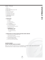
INSTALLATION
Ducting Calculation Sheet ......................................................................................
Mounting Height and Clearance .......................................................................
Ducting .....................................................................................................................................
Specifications .....................................................................................................................
Internal Blower ...................................................................................................................
Preparing Hood for External Blower ..............................................................
Mounting the Hood .......................................................................................................
External Blower Specifications ...........................................................................
External Blower ................................................................................................................
4
5
6
7
8-9
10
11-14
15
16-17
FEATURES & CONTROLS
Controls Overview .......................................................................................................... 18-19
MAINTENANCE
Cleaning .................................................................................................................................. 20
Lights ......................................................................................................................................... 21
TROUBLE SHOOTING ....................................................................................................... 22
WARRANTY ............................................................................................................................... 23
LIST OF ACCESSORIES/PARTS ............................................................................. 24
EXPLODED VIEW DIAGRAM ..................................................................................... 25-26
1
Table of Contents
SAFETY NOTICE ........................................................................................................................ 2
LIST OF MATERIALS ........................................................................................................... 3
WWWZEPHYRONLINECOM
,PSRUWDQWVDIHW\1RWLFH
5($'$1'6$9(7+(6(,16758&7,216
:$51,1*
4/ 2%$5#% 4( % 2 )3 +/ &&)2 % / 2 % ,% # 42 )# 3(/# + $/ ./453% 4( )3 &!.7 )4( !.9 3 / ,)$3 4!4%
30% % $ #/.42/, $%6 )# %
:$51,1*
4/ 2% $5#% 4( % 2 )3 +/ &&)2 % % ,% # 42 )# 3( / # + / 2 ).*5 294/ 0 % 2 3/. 3 / " 3 % 26% 4( % &/ ,,/ 7 ).'
A 5SE THISUNITONLYINTHEMANNERINTENDEDBYTHEMANUFACTURER)FYOUHAVEQUESTIONS CONTACTTHEMANUFACTURER
B"EFORE SERVICINGORCLEANINGUNIT SWITCHPOWEROFFATSERVICEPANELANDLOCKTHESERVICEDISCONNECTINGMEANSTOPREVENTPOWERFROMBEING
SWITCHEDONACCIDENTALLY
7HENTHESERVICEDISCONNECTINGMEANSCANNOTBELOCKEDSECURELYFASTENAPROMINENT WARNINGDEVICESUCHASTAGTOTHESERVICEPANEL
&$87,21
&OR'ENERAL6ENTILATING5SE /NLY$ONOT5SE TO%XHAUST(AZARDOUSOR%XPLOSIVE-ATERIALSAND6APORS
7DNHFDUHZKHQXVLQJFOHDQLQJDJHQWVRUGHWHUJHQWV6XLWDEOHIRUXVHLQKRXVHKROGFRRNLQJDUHD
:$51,1*
4/ 2%$5# % 4( % 2 )3 +/ &!2! .' % 4/ 0 '2 % !3 % &)2 %
A .EVERLEAVESURFACE UNITSUNATTENDEDATHIGHSETTINGS"OILOVERSCAUSE SMOKINGANDGREASYSPILLOVERSTHATMAYIGNITE (EATOILSSLOWLYONLOW
ORMEDIUMSETTINGS
B !LWAYSTURNHOOD/.WHENCOOKINGATHIGHHEATORWHENCOOKINGFLAMBEINGFOODIE#REPES 3UZETTE#HERRIES *UBILEE0EPPERCORN
"EEF &LAMBE
C #LEANVENTILATING FANSFREQUENTLY'REASE SHOULDNOTBEALLOWEDTOACCUMULATEONFANORFILTER
D 5SE PROPERPANSIZE!LWAYSUSECOOKWAREAPPROPRIATEFORTHESIZEOFTHESURFACE ELEMENT
:$51,1*
4/ 2% $5# % 4( % 2 )3 +/ &).*5294/ 0 %23/. 3 ).4( % %6 % .4/ &!2! .' % 4/ 0' 2 % !3 % &)2 % / " 3 % 26% 4( % &/ ,,/7 ).' A 3- /4(%2 &,! -%3 WITHACLOSEFITTINGLID COOKIESHEETORMETALTRAYTHENTURNOFFTHEBURNER" % #!2% &5,4/0 2 %6 % .4"52 .3
)FTHEFLAMESDONOTGOOUTIMMEDIATELY % 6!# 5!4% !.$#!,,4( % &)2 % $% 0!24-% .4
B .%6 % 2 0)# + 50!&,!-) .'0!.9OUMAYBEBURNED
C $/./453 % 7!4% 2INCLUDINGWETDISHCLOTHSORTOWELSAVIOLENTSTEAMEXPLOSIONWILLRESULT
D 5SE ANEXTINGUISHER/.,9IF
9OUKNOWYOUHAVEACLASS !" #EXTINGUISHERANDYOUALREADYKNOWHOWTOOPERATEIT
4HEFIREISSMALLANDCONTAINEDINTHEAREAWHEREITSTARTED
4HEFIREDEPARTMENTISBEINGCALLED
9OUCANFIGHTTHEFIREWITHYOURBACKTOANEXIT
"ASED ONh+ITCHEN&IRE3A FETY4IPSvPUBLISHEDBY.&0!
:$51,1*
4/ 2 % $5# % 4( % 2 )3 +/ &&)2 % % ,% # 42 )# 3(/# + / 2 ).*5294/ 0%2 3/.3 / " 3 % 26% 4( % &/ ,,/7 ).' A )NSTALLATION7ORKAND%LECTRICAL7IRING-USTBE$ONEBY1UALIFIED0ERSONS )N!CCORDANCEWITHALL!PPLICABLE#ODESAND3TANDARDS
)NCLUDING&IRE2ATED #ONSTRUCTION
B 3UFFICIENTAIRISNEEDEDFORPROPERCOMBUSTION ANDEXHAUSTINGOFGASES THROUGHTHEFLUECHIMNEYOFFUELBURNINGEQUIPMENT TOPREVENTBACK
DRAFTING &OLLOWTHEHEATINGEQUIPMENT MANUFACTURERSGUIDELINEANDSAFETYSTANDARDSSUCHASTHOSEPUBLISHEDBYTHE.ATIONAL&IRE0ROTECTION
!SSOCIATION.&0!ANDTHE!MERICAN3 OCIETYFOR(EATING2EFRIGERATIONAND!IR#ONDITIONING%NGINEERS!3 ( 2 !% ANDTHELOCALCODEAUTHORITIES
C 7HENCUTTINGORDRILLINGINTOWALLORCEILING DONOTDAMAGEELECTRICALWIRINGANDOTHERHIDDENUTILITIES
D $UCTEDFANSMUSTALWAYSVENTTOTHEOUTDOORS
:$51,1*
4/ 2%$5# % 4( % 2 )3 +/ &&)2 % 53 % / .,9-% 4!,$5 # 47 / 2 +
&$87,21
4OREDUCERISKOFFIREANDTOPROPERLYEXHAUSTAIRBESURETODUCTAIROUTSIDE$ONOTVENTEXHAUSTAIRINTO SPACESWITHINWALLSORCEILINGSORINTO
ATTICSCRAWLSPACES ORGARAGES
&$87,21 AND
%LECTRIC
3HOCK )NSTALL 4HIS
/NLY WITH
2EMOTE "LOWER
4O 2EDUCE THE 2ISK OF &IRE
2ANGE (OOD
-ODELS
# " % 2ATED
-AXIMUM AMP 6AC (Z OR )NTEGRAL "LOWERS -ANUFACTURED BY :EPHYR 6ENTILATION -ODELS # " )
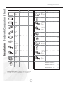
,ISTOF-ATERIALS
"\Ê
/*ÝÝ(OOD
"AFFLE&ILTERS
'567HALOGENBULBS
5TENSIL2AILS
4ELESCOPIC$UCT#OVERS
4ELESCOPIC2ODS3ETS
!NGLE"RACKETSv
!NGLE"RACKETSv
#EILING-OUNTING"RACKET
)NTERNAL&LANGE
-OTOR(OUSING
(!2$7!2%0!#+%4
#OUPLERS
!NCHORS
v7OOD3CREWS
v7OOD3CREWS
v7ASHERS
v3ELF4APPING3CREWS
v3CREWSXMM
MM)NTERNAL$IAMETER7ASHERS
!DHESIVE&ASTENERS
#ABLE4IES
3-!,,(!2$7!2%0!#+%4
3HORT3ET3CREWS
-EDIUM3ET3CREWS
4OOL
(!2$7!2%0!#+%4&/2%,%#42)#!,#/..%#4)/.!.$%84%2.!,",/7%2#/..%#4)/.
%XTERNAL&LANGEWITH!TTACHEDv#OLLAR
*UNCTION"OXWITH7IRES
%XTERNAL"LOWER7IRING"OXWITH7IRES
v3ELF4APPING3CREWS
%LECTRICAL#ONNECTION7IRING
MM)NTERNAL$IAMETER7ASHERS
./$5#4).')302/6)$%$
%84%2.!,!.$).4%2.!,",/7%23/,$3%0!2!4%,9
-AKESURETOREMOVETHEPROTECTIVEFILMOFFOFTHEHOODBEFOREINSTALLATIONINORDERTOMAKEREMOVALOFTHEFILM
EASIER"ECAREFULNOTTOSCRATCHTHESTAINLESSSTEELWHILEINSTALLING
Installation - Ductwork Calculation Sheet
www.zephyronline.com
Equivalent number
length x used =
Duct pieces
Equivalent number
length x used =
Duct pieces
Total
Total
3 1/4” x 10” 1 Ft.
Rect.,
straight
x(
) =
Ft.
6” Round
wall cap
with damper
30 Ft.
x(
) =
Ft.
7” Round,
straight
1 Ft.
x(
) =
Ft.
6” Round,
roof cap
30 Ft.
x(
) =
Ft.
7” Round,
straight
1 Ft.
x(
) =
Ft.
6” round to
1 Ft.
3 1/4” x 10”
rect.
transition
x(
) =
Ft.
3 1/4” x 10” 15 Ft.
Rect. 900
elbow
x(
) =
Ft.
x(
) =
Ft.
3 1/4” x 10” 9 Ft.
Rect. 450
elbow
x(
) =
Ft.
6” round to
16 Ft.
3 1/4” x 10”
rect.
transition
900 elbow
7” Round,
900 elbow
15 Ft.
x(
) =
Ft.
3 1/4” x 10” 24 Ft.
Rect. 900
flat elbow
x(
7” Round,
450 elbow
9 Ft.
x(
) =
Ft.
3 1/4” x 10” 30 Ft.
Rect.
wall cap
with damper
x(
7” Round
wall cap
with damper
30 Ft.
x(
) =
Ft.
3 1/4” x 10” 5 Ft.
Rect. to
6” round
transition
x(
) =
Ft.
7” Round,
roof cap
30 Ft.
x(
) =
Ft.
3 1/4” x 10” 15 Ft.
Rect. to
6” round
transition
900 elbow
x(
) =
Ft.
7” round to
8 Ft.
3 1/4” x 10”
rect.
transition
x(
) =
Ft.
) =
Ft.
15 Ft.
x(
) =
Ft.
7” round to
15 Ft.
3 1/4” x 10”
rect.
transition
900 elbow
x(
6” Round,
900 elbow
6” Round,
450 elbow
9 Ft.
x(
) =
Ft.
Subtotal column 2 =
Ft.
Subtotal column 1 =
Ft.
Total ductwork
Ft.
) =
) =
Subtotal column 1 =
Ft.
Ft.
Ft.
Maximum Duct Length: For satisfactory air movement, the total
duct length of a 3 1/4” x 10” rectangular, 6” or 7” or 8” diameter
round duct should not exceed 100 equivalent feet.
4
=
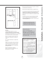
-AXIMUMMOUNTHEIGHTSHOULDBENOHIGHERTHAN
-IN-AX
-IN-AX
-IN-AXv
)TISIMPORTANTTOINSTALLTHEHOODATTHEPROPERMOUNTING
HEIGHT (OODSMOUNTEDTOOLOWCOULDRESULTINHEAT
DAMAGEANDFIREHAZARDWHILEHOODSMOUNTEDTOOHIGH
WILLBEHARDTOREACHANDWILLLOOSEITSPERFORMANCEAND
EFFICIENCY
)FAVAILABLE ALSOREFERTORANGEMANUFACTURERgSHEIGHT
CLEARANCEREQUIREMENTSANDRECOMMENDEDHOOD
MOUNTINGHEIGHTABOVERANGE!LWAYSCHECKYOURLOCAL
CODESFORANYDIFFERENCES
-INIMUM CEILING HEIGHT OF v (OOD
MOUNTED AT v ABOVE COOKING SURFACE
-AXIMUM CEILING HEIGHT OF (OOD
MOUNTED AT ABOVE COOKING SURFACE
-INIMUM
$UCT
3IZE
$5#4).'
2OUNDvMINIMUMAT CFM
2OUNDvTO vMINIMUM AT CFM
2ECT ANGULARv Xv MINIMUMONLYIF
USINGINTERNAL BLOWERAT CFM5SING
RECTANGULARDUCTWORKWILLREQUIREATRANSITION
ADAPTERNOTPROVIDEDBUTREADILYAVAILABLEAT
MOSTHARDWARESTORES
!MINIMUMOFvROUNDOR X
RECTANGULARDUCTWORKMUSTBEUSEDTOMAINTAIN
MAXIMUMAIRFLOWEFFICIENCYWITHTHE CFM
INTERNAL BLOWER!MINIMUMOFvTO vROUNDMUST
BEUSEDWITHTHE CFMEXTERNALBLOWER
!LWAYSUSERIGIDTYPEMETALDUCTWORKONLY
&LEXIBLEDUCTSCOULDRESTRICTAIRFLOWBYUP
TO
$!-!'%3()0-%.4
).34!,,!4)/.
5SE CALCULATIONWORKSHEETTOCOMPUTETOTAL
DUCTWORK
s 0LEASE FULLYINSPECTUNITFORDAMAGE
BEFOR E INSTALLATION
!,7!93WHENPOSSIBLEREDUCETHENUMBER
ORTRANSITIONSANDTURNS)FAREDUCERISUSED
INSTALLALONGREDUCERINSTEADOFAPANCAKE
REDUCER2EDUCE DUCTSIZEASFARAWAYFROM
OPENINGASPOSSIBLE
s )FTHEUNITIS DAMAGED INSHIPMENT RETURN
THEUNITTOTHESTOREINWHICHITWASBOUGHT
FORREPAIRORREPLACEMENT
s )FTHEUNITIS DAMAGED BYTHECUSTOMER
REPAIRORREPLACEMENTISTHERESPONSIBILITY
OFTHECUSTOMER
)FTURNSORTRANSITIONSAREREQUIRED
)NSTALLASFARAWAYFROMOPENINGANDASFAR
APARTBETWEENASPOSSIBLE
s )FTHEUNITIS DAMAGED BYTHEINS TALLER IF
OTHERTHANTHECUSTOMERREPAIROFREPLACE
MENTMUSTBEMADEBYARRANGEMENT
BETWEENCUSTOMERANDINSTALLER
,QVWDOODWLRQ0RXQWLQJ+HLJKW&OHDUDQFH
-INIMUMMOUNTHEIGHTBETWEENRANGETOPTOHOODBOT
TOMSHOULDBENOLESS THAN
)NSTALLATION$UCTING
WWWZEPHYRONLINECOM
7!2.).'&)2%(!:!2$
.%6%2EXHAUSTAIRORTERMINATEDUCTWORKINTOSPACESBETWEENWALLSCRAWLSPACESCEILINGATTICSORGARAGES!LLEXHAUSTMUST
BEDUCTEDTOTHEOUTSIDE
5SESINGLEWALLRIGID-ETALDUCTWORKONLY
&ASTENALLCONNECTIONSWITHSHEETMETALSCREWSANDTAPEALLJOINTSWCERTIFIED3ILVER4APEOR$UCT4APE
3OME$UCTING/PTIONS
%XTERNAL"LOWER
SIDEWALLCAP
WGRAVITYDAMPER
3OFFITORCRAWLSPACE
2OOF0ITCHW
&LASHING#AP
%XTERNAL
"LOWER
3OFFITORCRAWLSPACE
h
v
v
³
³
³
v
v
v
2
-INv-AXv
v
v
v
v
vvv
v
/
v
v
v
v
,QVWDOODWLRQ6SHFLILFDWLRQV
h
h
h
-INh-AXv
h
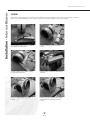
Installation - Internal Blower
www.zephyronline.com
ATTENTION
The following are intructions for installing internal blower model CBI-600. For instructions on preparing for external
blower model CBE-1000 please turn to page “10”. Before installing, verify that motor spins freely.
The internal blower kit consists of the blower
and capacitor box with wiring.
1. Remove existing screws from blower
housing.
2. Attach capacitor box to blower housing
using the removed screws.
3. Attach motor connector to capacitor box
connector.
4. Position internal flange over blower
housing.
5. Attach (4) 1/2” 5x15mm screws and (4)
10mm washers to hold flange to blower
housing.
8
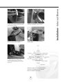
7. Attach grounding wires from junction box
and motor to grounding screw as shown.
8. Place blower with attached flange into
motor housing as shown on Fig-A.
9. Attach using 1/2” self tapping screws to
secure in place.
10. Attach other end of capacitor box
connector and junction box connector to
control board box and wiring box connector
inside hood.
Continue to page “11” for hood installation
instructions and page “15” for external
blower installation instructions.
9
Installation - Internal Blower
6. Attach junction box to internal flange using
provided 1/2” self tapping screws and 4mm
internal diameter washers.
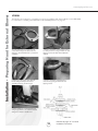
Installation - Preparing Hood for External Blower
www.zephyronline.com
ATTENTION
The following are instructions on preparing your hood for installation with external blower model CBE-1000.
For instructions on installing internal blower model CBI-600 please turn to page “8”.
The external blower kit consists of an 8”
collar, external flange and external blower
wiring box. The external blower is purchased
separately.
1. Position and attach external blower wiring
box and junction box using provided 1/2” self
tapping screws and 4mm internal diameter
washers.
2. Attach grounding wires from external
blower wiring box and junction box to
grounding screw as shown in Fig-A.
3. Position and attach external flange to
motor housing using provided 1/2” self
tapping screws.
4. Attach junction box and external blower
wiring box connectors to control board and
wiring box connectors inside hood.
10
Continue to page “11” for hood
installation instructions.
&/
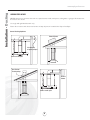
0RXQWLQJ
+ROHV
0DUNLQJIRU &RXSOHU
&/
1DUURZ(Q
7DEV
$GG%ORFNLQJV
7DEV
&HLOLQJ%UDFNHW
,QVWDOODWLRQ 0RXQWLQJ WKH +RRG
&HLOLQJ
8VLQJWKHSURYLGHGWHPSODWHPDUNWKHFHQWHUSRLQWLQEHWZHHQWKHPRXQWLQJKROHV'HWHUPLQHWKHORFDWLRQIRU
PRXQWLQJ\RXUKRRGSODFHWHPSODWHRQFHLOLQJDQGPDUNGULOOWKHFHQWHUSRLQWIRUWKHFHLOLQJPRXQWLQJEUDFNHWDQGWKH
IRXUFRUQHUKROHVZKHUHWKHWHOHVFRSLFURGFRXSOHUVZLOODWWDFKWRWKHFHLOLQJ 1RWH7HPSODWHLVORFDWHGRQWRSRIFDUWRQ
&XWRXWKROHIRUWKHGXFWZRUN
$GGDQGVHFXUH ZRRG EORFNLQJV PLQLPXP [ VWXGV WR FHLOLQJ MRLVWV
&HQWHUPDUNDQGIDVWHQ FHLOLQJ PRXQWLQJ SODWH RQWR FHLOLQJ ZKHUH KRRG LV WR EH KXQJ0DNH VXUHWKH WDEV
RQ
WKH
FHLOLQJEUDFNHWDUHSRVLWLRQHGWRWKHVLGHVDVVKRZQLQWKHGLDJUDP7KHGXFWFRYHUV ZLOO DWWDFKWRWKHVHWDEV
$WWDFKFRXSOHUVWRPDUNHGFRUQHUVRIFHLOLQJXVLQJWKHSURYLGHG´ZRRGVFUHZV0DNHVXUHWKHQDUURZRSHQLQJRI
WKHFRXSOHULVIDFLQJGRZQ
3RVLWLRQHOHFWULFDOZLULQJDQGGXFWZRUN
(/(&75,&$/:$51,1*
$OO(OHFWULFDOZRUNPXVWE\SHUIRUPHGE\TXDOLILHGHOHFWULFLDQRUSHUVRQZLWKVLPLODUWHFKQLFDONQRZKRZ
DQGEDF NJURXQG
)RUSHUVRQDO VDIHW\ UHPRYH KRXVH IXVH RU RSHQ FLUFXLW EUHDNHU
EHIRUH
EHJLQQLQJ LQVWDOODWLRQ
'RQRWXVHH[WHQVLRQFRUGRUDGDSWHUSOXJZLWKWKLVDSSOLDQFH
)ROORZ1DWLRQDO(OHFWULFDO&RGHVRUSUHYDLOLQJORFDOFRGHVDQGRUGLQDQFHV
(OHFWULFDO6XSSO\
7KLVDSSOLDQFH UHTXLUHV D9
+]
HOHFWULFDO
VXSSO\DQG
FRQQHFWHG
WR
DQ
LQGLYLGXDO
SURSHUO\
JURXQGHG
EUDQFK
FLUFXLW
SURWHFWHGE\DRUDPSHUHWLPHGHOD\FLUFXLWEUHDNHU:LULQJPXVWEHZLUHZLWKJURXQG3OHDVH UHIHU WR ODEHO SODFHG
RQMXQFWLRQER[
Installation - Mounting the Hood
www.zephyronline.com
1. Mount motor housing to the range hood body using (10) 1/2” self tapping screws.
2. Determine height of hood, measure and select either 27 3/8” or 35 3/8” angle brackets and attach (4) of
them to the motor housing using (8) 1/2” self tapping screws (2) for each angle bracket.
3. Slide duct covers over motor housing. Make sure bottom duct cover with cut-out is facing the front and back of
the hood.
12
;A=
$UCTWORK
%LECTRICALWIRING
;B=
,IFTASSEMBLEDUNITANDATTACHALLANGLEBRACKETSTOCEILINGBRACKET-AKESURETHETABSONEACHANGLE
BRACKETSAREFACINGTHEOUTSIDE4HEANGLEBRACKETSWILLFITBETWEENTHESLOTSONTHECEILINGBRACKET/NEHALFOF
THEANGLEBRACKETWILLBEONTHEOUTSIDEOFTHECEILINGBRACKETANDTHEOTHERHALFWILLBEONTHEINSIDEOFTHECEILING
BRACKET!TTACHUSINGPROVIDEDvSELFTAPPINGSCREWS2EFERTODIAGRAM;A=
3LIDEDUCTCOVERSUPANDATTACHDUCTWORKANDELECTRICALWIRINGTOTOPOFMOTORHOUSING2EFERTODIAGRAM;B=
)NSTALLATION-OUNTINGTHE(OOD
4AB
Installation - Mounting the Hood
www.zephyronline.com
Telescopic Rod Installation
Set
screws
1. Install telescopic rod (thicker end down) into coupler
on top of hood and secure with medium set screw.
Attach screw using provided tool.
2. Extend telescopic rod towards the ceiling and
insert thin end of rod into ceiling coupler. Attach
a medium set screw in the middle where the
two rods attach to each other.
3. Attach medium set screw into the ceiling coupler
to secure it in place. Repeat these steps for each
telescopic rod.
Tool
Set
screw
Front
Back
Utensil Rail Installation
1. Attach utensil rail to long side of hood canopy. A small hole has been pre-drilled into the canopy to provide a
starting point to attach the first utensil rail post. After the first post is line up with the hole, gently slide the rest
of the rail onto canopy. (note: be careful not to scratch the stainless steel when performing this step, this is
why there is a starter hole).
2. Attach a short set screw into each post in order to hold utensil rail onto canopy. Do the same for the other side.
14
4HEFOLLOWINGINSTRUCTIONSDESCRIBETHEINSTALLATIONOFTHE#"%EXTERNALBLOWERFORUSEWITH:EPHYRMODELS#40
#/+OR#3(RANGEHOODSONLY
&IG
&IG
490)#!,).34!,,!4)/.
2//&-/5.4
%LBOW
$UCT
/543)$%7!,,-/5.4
%LBOW
2OOF
(OOD
(OOD
2ECOMMENDEDFORUSEONLYOVERCONVENTIONALDOMESTICGASANDELECTRICRANGES
/UTSIDE7ALL
)NSTALLATION %XTERNAL "LOWER 3PECIFICATIONS
./4%
Installation - External Blower
www.zephyronline.com
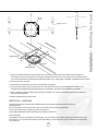
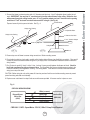
1. Remove and discard shipping brackets and wood support (attached to sides of motor and inlet collar). Fig. - 7
BEFORE INSTALLING, check to see if blower wheel turns freely and does not rub on motor brackets. Check damper door
to be sure it moves freely and spring returns door to closed position.
2. Provide 14” x 18” hole through the roof or wall as shown in Fig. - 2. For reference, location of 10” duct connection and
wiring connection is shown.
3. Install blower on roof or wall, with discharge
(screened end) pointing down, according to
standard roofing procedures.
NOTE: Front discharge edge should be on top
of shingles and rear and side edges under shingles.
Unit must be sealed between roof or wall and under
side of flange with roofing mastic to prevent leaks.
Fig-2
14"
For installation on a flat roof, or roofs with pitch
of less than 1 1/2’ in 12”, install blower on curb
as shown in Fig. - 3. Position curb on sloping roof
with 2” dimension facing down slope. Position curb
on flat roofs so that discharge points away from
prevailing wind.
Top View
Down Slope
of
Roof or Wall
18"
10 1/2"
Fig-7
4 1/2"
7 3/4"
1 1/2"
Remove
Remove
Fig-3
Remove
1 1/2"
6"
2"
30"
24"
16
([WHUQDO%ORZHU
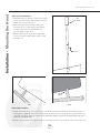
7DSHDQGVFUHZDOOMRLQWVWRSUHYHQWDLUOHDNV6HH)LJ
5RRI
6KLQJOH2YHU)ODVKLQJ
µ$GMXVWDEOH(OERZ
6KLQJOH8QGHU)ODVKLQJ
µ'LDPHWHU'XFW:RUN
µWRµ7UDQVLWLRQ$GDSWHU
&HLOLQJ
6FUHZDQG7DSH-RLQW
&HLOLQJ%UDFNHW
&RQGXLW
)LJ
´'XFW:RUN
+RRG
)LJD
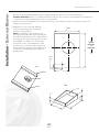
5HPRYHWRSFRYHURIEORZHUWRDFFHVVZLULQJFRQQHFWLRQV5HWDLQPRXQWLQJVFUHZV
5XQHOHFWULFDOFRQGXLWSHUORFDOFRGHWRFRQGXLWRXWOHWLQERWWRPSODWHRIEORZHUXVHOLTXLGWLJKWFRQQHFWLRQ2WKHUHQGRI
FRQGXLWZLOOFRQQHFWWRH[WHUQDOEORZHUZLULQJER[LQ\RX=HSK\UKRRG6HHLQVWDOODWLRQLQVWUXFWLRQVHDUOLHULQPDQXDOIRU
ZLULQJORFDWLRQ
5XQZLUHVLQFRQGXLWEODFNZKLWHEOXHUHGDQGJUHHQJURXQGEHWZHHQWKHEORZHUDQGKRRG&KHFNIRU
ORFDOFRGHFRPSOLDQFHIRUVW\OHDQGJDXJHRIZLUHV7KHJURXQGZLUHVKDOOKDYHDVXLWDEOHJDXJHDFFRUGLQJWRWKH
(OHFWULFDO&RGHDQG/RFDO5HJXODWLRQV6HH)LJIRUZLULQJGHWDLOV7KHVHZLUHVZLOOFRQQHFWWRWKHH[WHUQDOEORZHU
ZLULQJER[RQWRSRIWKHKRRG
&$87,21%HIRUHZLULQJWKHXQLWVZLWFKSRZHURIIDWVHUYLFHSDQHODQGORFNWKHVHUYLFHGLVFRQQHFWLQJPHDQVWRSUHYHQW
SRZHUIURPEHLQJVZLWFKHGRQDFFLGHQWDOO\
5HSODFHFRYHURQWREORZHUIURPVWHSDQGVHFXUHZLWKVFUHZVSURYLGHG$OOVFUHZVPXVWEHLQSODFHRQFRYHU
)LJ
&%(:,5,1*',$*5$0
([WHUQDO%ORZHU
:LULQJ%R[
KRRG
:KLWHFRPPRQ
%ODFNKLJK
%OXHPHG
5HGORZ
*UHHQJURXQG
-XQFWLRQ%R[
&%(
&%(+36SHHG0RWRU9$&+]$PS&LUFXLW5HTXLUHG
,QVWDOODWLRQ([WHUQDO%ORZHU
&RQQHFWWKHEORZHUWRH[KDXVWV\VWHPZLWKDµGLDPHWHUPHWDOGXFWRQO\8VHµDGMXVWDEOHHOERZWRDGMXVWWRURRI
DQJOH,03257$17<RXPXVWUXQµURXQGGXFWZRUNIURPWKHH[WHUQDOEORZHUWRWKHFHLOLQJ%HIRUHWKHGXFW
ZRUNSDVVHVWKURXJKWKHFHLOLQJEUDFNHWXVHDµWRµWUDQVLWLRQDGDSWHUDQGUXQµGXFWZRUNWRWKHRSHQLQJ
RQWKHKRRG7KHµGXFWZRUNUXQVKRXOGQRWH[FHHGµLQOHQJWKVHH)LJD
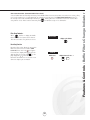
Features & Controls - Touch Controls & Features
www.zephyronline.com
1. Blower On/Off
By pressing
, the blower is switched On and Off.
2. Speed Selection
The 3 speed levels are selected by presing
level selected.
to decrease and
to increase speed level. The display indicates
3. Delay Off
This is used for programmed shut down of blower and lights 15 minutes after the function is activated. Press
once,
a dot flashes in the lower right hand side of display
indicating the function is on. The hood will completely shut down
in 15 minutes.
4. Lights On/Off/Dim
Switch lights On and Off by pressing key
once. To dim lights, press and hold
for 2 seconds.
5. Advance Display Functions
Filters Clean Reminder (Baffle):
After every 30 hours of use, the display will start flashing an
possible clogs.
reminding you to clean the baffle filters from residue and
The standard Baffle Filters are required to be cleaned frequently and as recommended in order to maintain blower
efficiency. If improperly maintained, residue from cooking will sift though filters and cause damage to hood blowers
and other sensitive components; and possibly clog duct work and create a fire hazard.
18
Filter Clean Reminder:
When
flashes on display, the baffle
filters installed are required to be cleaned.
This will occur after every 30 hours of use.
Clean Filters
display <A> flashes
Re-setting Function:
Reset the Filter Clean Reminder timer when
filters are cleaned and re-installed (with
hood off). Press and hold
for approx.
5 seconds, the display will appear; hold for
approximately 5 seconds until
on display disappears
. The Filter Clean
Reminder function is now re-set and a new
30 hours elapse cycle is initiated.
To Reset
hold 5 secs.
19
display from <C> to < >
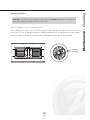
Features & Controls - Baffle Filters Change Indicator
Filter Clean Reminder (Standard Baffle Filters fitted):
A set of baffle filters are fitted by the factory. These Baffle Filters are intended to filter out residue from cooking. They
need not be replaced on a regular basis but are required to be kept clean. The Filter Clean Reminder function in
the microprocessor will automatically indicate by a
flashing when the metal filters need to be cleaned after
every 30 hrs. of use. Filters can be cleaned by hand with non-abrasive soap or in a dishwasher.
-AINTENANCE#LEANING
WWWZEPHYRONLINECOM
3URFACE-AINTENANCE
#LEANPERIODICALLYWITHHOTSOAPYWATERANDCLEANCOTTONCLOTH$ONOTUSECORROSIVEORABRASIVEDETERGENTORSTEEL
WOOLSCOURINGPADSWHICHWILLSCRATCHANDDAMAGESURFACE
&ORHEAVIERSOILUSELIQUIDDEGREASER
!FTERCLEANINGYOUMAYUSENONABRASIVESTAINLESSSTEELPOLISHCLEANERSTOPOLISHANDBUFFOUTTHESTAINLESSLUSTER
ANDGRAIN!LWAYSSCRUBLIGHTLYWITHCLEANCOTTONCLOTHANDWITHTHEGRAIN
$ONOTUSEANYPRODUCTCONTAININGCHLORINEBLEACH$ONOTUSEhORANGEvCLEANERS
"AFFLE&ILTERS
4HE-ETAL&ILTERSFITTEDBYTHEFACTORYAREINTENDED
TOFILTEROUTRESIDUEANDGREASEFROMCOOKING4HEY
NEEDNOTBEREPLACEDONAREGULARBASISBUTARE
REQUIREDTOBEKEPTCLEAN
&ILTERSSHOULDBECLEANEDAFTEREVERYHOURSOF
USE5SETHE&ILTER#LEAN2EMINDERFUNCTIONONTHE
CONTROLSTODETERMINEWHENFILTERSREQUIRECLEANING
(ANDLES
2EMOVEANDCLEANBYHANDORINDISHWASHER
3PRAYDEGREASINGDETERGENTANDLEAVETOSOAKIF
HEAVILYSOILED
2EMOVEFILTERSBYSLIDINGAWAYFROMCENTEROFHOOD
ANDPULLINGDOWN
$RYFILTERSANDREINSTALLBEFOREUSINGHOOD
2EPLACING"AFFLE&ILTERS
3HOULDFILTERSWEAROUTDUETOAGEANDPROLONGED
USEREPLACEWITHFOLLOWINGPARTNUMBER
CAUTION: Light bulbs become extremely hot when turned on. DO NOT touch bulbs until switched off
and cooled. Touching hot bulbs may cause serious burns.
Make sure all power is turned off and bulbs are not hot.
Remove bulb by pressing both ends of the metal retaining clip together, the light socket will now extend from the hood
allowing you to remove the bulb. (Be careful when releasing retaining clip as it is under pressure to hold it in place)
Replacement bulbs are available at most stores which sell light bulbs. Purchase type GU-10, 120V, 50W.
Press together
to release clip
21
Maintenance - Cleaning
Replacing Light Bulbs:
Trouble Shooting
www.zephyronline.com
Issue
Cause
What to do
After installation, the unit
doesn’t work?
1. The power source is not turned ON.
1. Make sure the circuit breaker and the unit’s
power is ON.
2. The power line and the cable locking connector is
not connecting properly.
2. Check the power connection with the unit is
connected properly.
3. The switch board and control board wirings
are disconnected.
3. Make sure the wirings between the switch
board and control board are connected properly.
4. On the switch board, Black/White wire of White
wire is disconnected.
4. Make sure the Black/White wire or White wire
connects properly.
5. The switch board or control board is defective.
5. Change the switch board or control board.
1. The motor is defective, possible seized.
1. Change the motor.
2. The thermally protected system detects if the motor
is too hot to operate and shuts the motor down.
2. The motor will function properly after the
thermally protected system cool down.
3. Damaged capacitor.
3. Change the capacitor.
1. The motor is not secure in place.
1. Tighten the motor in place.
2. Damaged blower wheel/makes noise.
2. Change the motor.
3. The hood is not secured in place.
3. Check the installation of the hood.
The motor is working,
but the lights are not.
1. Defective halogen bulb.
1. Change the halogen bulb.
2. The light bulb is loose.
2. Tighten the light bulb.
The hood is not venting
out properly.
1. The hood might be hanging to high from the
cook top.
1. Adjust the distance between the cook top
and the bottom of the hood within 24” and
32” range.
2. The wind from the opened windows or opened
doors in the surrounding area are affecting the
ventilation of the hood.
2. Close all the windows and doors to eliminate the
outside wind flow.
3. Blocking in the duct opening or ductwork.
3. Remove all the blocking from the duct work or
duct opening.
4. The direction of duct opening is against the wind.
4. Adjust the duct opening direction.
5. Using the wrong size of ducting.
5. Change the ducting to at least 6” or higher
for the internal blower and 8” or higher for the
external blower.
1. Baffle filter is loose.
1. Remove filter and reinstall it or change the
baffle filter.
1. Control board needs to be reset.
1. Turn circuit breaker which controls the hood off
for at least 15 minutes.
Turn it back on and this should fix the problem.
1. Defective control board.
1. Replace control board.
Light works, but motor is
not turning.
The unit is vibrating.
Filter is vibrating.
After hood has been
installed for a period of
time, it stopped working.
22
Staple your receipt here.
Proof of the original purchase
date is needed to obtain service
under the warranty.
1-888-880-8368
TO OBTAIN SERVICE UNDER WARRANTY: You must present proof of original purchase date.
Please keep a copy of your dated proof of purchase (sales slip) in order to obtain service under warranty.
One Year Service Repair Warranty:
For one year from date of original purchase, we will provide free of charge, service labor to repair any failed parts or
components due to manufacturing defects.
Two Years Parts Warranty:
For two years from date of original purchase, we will provide free of charge, nonconsumable replacement parts or
components that failed due to manufacturing defects. Consumable parts not covered by this warranty include: Light Bulbs,
Metal and Carbon Filters.
Who is Covered:
This warranty is extended to the original purchaser for products purchased for ordinary home use in the 48 mainland states,
Hawaii and Washington D.C. In Canada and Alaska, this warranty is Limited.
There might be costs associated with
shipping the products to our designated service locations or you might need to pay service technician's travel costs, to have
the appliance repaired in-home.
This Warranty will be Voided when:
Product damaged through negligence, misuse, abuse, accident. Improper installation and failure to follow installation instructions. When product is used commercially or other than its intended purpose. Damaged because of improper connection with
equipment of other manufacturers. Repaired or modified by anyone other than Zephyr's Authorized Agents.
What is Not Covered:
Consumable parts such as light bulbs, filters, and fuses. Services outside of service area and the labor cost incurred in
connection with the removal, shipping and reinstallation cost, nor does it cover any other contingent expenses. The natural
wear of finish, and wear due to improper maintenance, use of corrosive and abrasive cleaning products, pads, and oven
cleaner products. Chips, dents or cracks due to abuse, misuse, freight damage, or improper installation. Service trips to your
home to teach you how to use the product. Damage of product caused by accident, fire, floods or act of God.
This warranty is valid in the United States and Canada. It is non-transferable and applies only to the original purchaser and does
not extend to subsequent owners of this product. Any applicable implied warranties, including the warranty of merchantability,
are limited in duration to a period of express warranty as provided herein beginning with the date of original purchase at retail
and, no warranties, whether express or implied, shall apply to this product thereafter. Have your product proof of purchase with date
ready for warranty issues
Or write to:
Zephyr Corporation
Service and Warranty Department
395 Mendell Street
San Francisco, CA 94124
23
W a rra nty
TO OBTAIN SERVICE UNDER WARRANTY:
or any Service Related Questions, please call:
,ISTOF0ARTSAND!CCESSORIES
WWWZEPHYRONLINECOM
0ART$ESCRIPTION 0ART
(ALOGEN"ULB'567
:"
!CCESSORY$ESCRIPTION
0ART
)NTERNAL"LOWERCFM #")
%XTERNAL"LOWERCFM
#"%
$UCT#OVER%XTENSION+IT
:#40
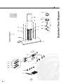
%XPLODED6IEW$IAGRAM
&73(6;
&73(6;
&73(6;
#40%38#40%38#40%38
0ART.UMBERS
WWWZEPHYRONLINECOM
2EF
0ART
$ESCRIPTION
0HPEUDQH+RUL]RQWDO
&RQWURO%RDUG
/('6ZLWFK%RDUG
+RXVLQJDQG&RYHU&RQWURO%RDUG
)LOWHU%DIIOH
+DORJHQ%XOE*89:
+
/LJKW6RFNHW*8
([WHUQDO%ORZHU.LW
&ROODU5RXQG
([WHUQDO%ORZHU:LULQJ%R[
([WHUQDO)ODQJH
-XQFWLRQ%R[:LWK:LULQJ+DUQHVV
([WHUQDO%ORZHU:LULQJ+DUQHVV
,QWHUQDO)ODQJH
'XFW&RYHU%RWWRP
'XFW&RYHU7RS
%UDFNHW$QJOH
%UDFNHW$QJOH
%UDFNHW&HLOLQJ
8WHQVLO5DLO&73(6;
8WHQVLO5DLO&73(6;
8WHQVLO5DLO&73(6;
&RXSOHU
5RG7HOHVFRSLF2XWHU
5RG7HOHVFRSLF,QQHU
1TY