1
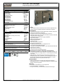
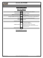
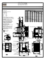
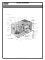
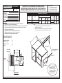
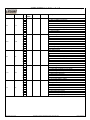
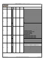
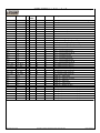
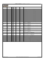
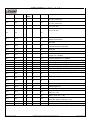
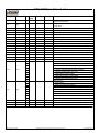
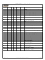
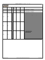
SECTION 01 64 10
SUBSTITUTION REQUEST FORM
TO:
SOLARC Engineering and Energy + Architectural Consulting
Business Office
223 W. 12th Avenue
Eugene, Oregon 97401
PROJECT:
Marion County Jail HVAC Improvements
4000 Aumsville Hwy
Salem, Oregon
SPECIFIED ITEM: 23 74 13
Section
2.01
Packaged Roof Top Air Conditioning Units
Paragraph
Description
The undersigned requests consideration of the following:
PROPOSED SUBSTITUTION: Manufacturer: Luxaire
Attached data includes product descriptions, specifications, drawings, photographs, performance and test
data adequate for evaluation of request including identification of applicable data portions.
Attached data also includes description of changes to Contract Documents and proposed substitution
requires for proper installation.
The undersigned certifies following items, unless modified by attachments, are correct:
1. Proposed substitution does not affect dimensions shown on drawings.
2. Undersigned pays for changes to building design, including engineering design, detailing, and
construction costs caused by proposed substitution.
3. Proposed substitution has no adverse effect on other trades, construction schedule, or specified
warranty requirements.
4. Maintenance and service parts available locally or readily obtainable for proposed substitution.
Undersigned further certifies function, appearance, and quality of proposed substitution are equivalent to
or superior to specified item.
Submitted by: ____________________________________
Steve Carter
Steve Carter
Digitally signed by Steve Carter
DN: cn=Steve Carter, o=Johnson Air Products,
ou, [email protected], c=US
Date: 2014.10.20 08:16:06 -07'00'
Signature: _______________________________________
Johnson Air Products
Firm: ___________________________________________
Address:________________________________________
2220 SE Ninth Ave
For use by Architect / Engineer:
x
☐ Approved
☐ Approved as noted
☐ Not Approved
☐ Received too late
Date: ___________________________________________
10/20/2014
B. Jacoby @ Solarc Eng.
10-21-14
Date: __________________________________________
503.233.0451
Tel: ___________________
503.234.5071 Fax: _____________________
Comments: _____________________________________
Attachments:_____________________________________
Submittal Data
_______________________________________________
_______________________________________________
Portland, OR 97214
MARION COUNTY JAIL
HVAC IMPROVEMENTS
By: ____________________________________________
SUBSTITUTION REQUEST FORM
01 64 10 - 1
Page: 1
6.5-12.5 Ton Package
Single Package R-410A Air Conditioner
Project Name: Jail HVAC Remediation
Unit Model #: ZW-07N12AWAZZ5
Quantity: 1 System: ZW-07N12AWAZZ5
Cooling Performance
Total capacity
Sensible capacity
Refrigerant type
Efficiency (at ARI)
Integrated eff. (at ARI)
Ambient DB temp.
Entering DB temp.
Entering WB temp.
Leaving DB temp.
Leaving WB temp.
Part load efficiency
Power input (w/o blower)
Sound power
87.3
66.1
R-410A
12.00
13.00
105.0
80.0
67.0
59.6
57.8
14.2
7.43
83
MBH
MBH
EER
IEER
°F
°F
°F
°F
°F
IPLV
kW
dB(A)
Gas Heating Performance
Entering DB temp.
Heating output capacity (Max)
Supply air
Heating input capacity (Max)
Leaving DB temp.
Air temp. rise
SSE
Stages
60
96
3000
120
89.6
29.6
80.0
2
°F
MBH
CFM
MBH
°F
°F
%
3000
1.0
884
1.73
Side
1.50
1.50
1.40
203
BELT
CFM
IWG
RPM
HP
HP
HP
kW
ft.
Electrical Data
Power supply
Unit min circuit ampacity
Unit max over-current protection
460-3-60 17.9 Amps
20 Amps
Dimensions & Weight
Hgt
51 in.
Len 89 in.
Weight with factory installed options
Wth
59 in.
1145 lbs.
Clearances
Right
Top
12 in.
72 in.
Front
Bottom
36 in.
0 in.
Back
Left
and each rooftop is completely computer-run tested prior to shipment.
Supply Air Blower Performance
Supply air
Ext. static pressure Blower speed
Max BHP of Motor (including service factor)
Duct location
Motor rating
Actual required BHP
Power input
Elevation
Drive type
7.5 Ton
• Luxaire Ovation units are manufactured at an ISO 9001 registered facility
36 in.
36 in.
Note: Please refer to the tech guide for listed maximum static pressures
Unit Features
• Unit Cabinet Constructed of Powder Painted Steel, Certified At 1000 Hours
Salt Spray Test (ASTM B-117 Standards)
• Through-the-Curb and Through-the-Base Utility Connections
• Either supply and/or return can be field converted from vertical to horizontal
•
•
•
•
•
•
•
•
•
•
•
•
Standard Unit Controller: Simplicity Control Board
• An integrated low-ambient control, anti-short cycle protection, lead-lag, fan
•
configuration without cutting panels.
Full perimeter base rails with built in rigging capabilities
Hinged Access Panels
Slide-Out Condensate Drain Pan
Reciprocating Compressor
Two Stage Cooling
Solid Core Liquid Line Filter Driers
Microchannel Condenser Coil
120 MBH Input Aluminized Steel, Two Stage Gas Heat
1.5 HP Standard Static Belt Drive Blower
Unit Ships with 2" Pleated Filters (MERV 7) with a Standard Filter Rack that
will Accept up to 4" Filters
Single Point Power Connection
Short Circuit Current: 5kA RMS Symmetrical
on and fan off delays, low voltage protection, on-board diagnostic and fault
code display.
Safety Monitoring - Monitors the high and low-pressure switches, the
freezestats, the gas valve, if applicable, and the temperature limit switch on
gas and electric heat units. The unit control board will alarm on ignition
failures, safety lockouts and repeated limit switch trips.
BAS Controller
• Simplicity Intelli-Comfort II Controller with SimplicityLINC Gateway to
BACnet MS/TP Protocol - Includes Supply Air, Return Air, Outside Air Temp
Sensors, and Air Proving Switch
Warranty
• One (1) Year Limited Warranty on the Complete Unit
• Five (5) Year Warranty - Compressors
• Ten (10) Year Warranty - Aluminized Steel Tubular Heat Exchangers
Unitary Sales Tool v1.5.8.0
Information is subject to change without notice. Check local codes.
Printed 10/20/2014
Page: 2
6.5-12.5 Ton Package
Single Package R-410A Air Conditioner
Project Name: Jail HVAC Remediation
Unit Model #: ZW-07N12AWAZZ5
Quantity: 1 System: ZW-07N12AWAZZ5
Factory Installed Options
ZW-07N12AWAZZ5
Product Category:
|
Z
Single Packaged R-410A Air Conditioner
Product Identifier:
W
12.2 EER / 13.0 IEER
Nominal Cooling Capacity:
-07
Heat Type and Nominal Heat Capacity:
N12
7.5 Ton
Two Stage Cooling
120 MBH Input Aluminized Steel, Two Stage Gas Heat
Airflow:
A
1.5 HP Standard Static Belt Drive Blower
Voltage:
W
460-3-60
Installation Options:
A
2" Pleated Filters (MERV 7)
Microchannel Condenser Coil
Additional Options:
ZZ
Simplicity® Intelli-Comfort II Controller with
SimplicityLINC® Gateway to BACnet MS/TP Protocol
Composite Drain Pan
Product Generation:
5
Field Installed Accessories
Unitary Sales Tool v1.5.8.0
Information is subject to change without notice. Check local codes.
Printed 10/20/2014
Page: 3
6.5-12.5 Ton Package
Single Package R-410A Air Conditioner
Project Name: Jail HVAC Remediation
Unit Model #: ZW-07N12AWAZZ5
Quantity: 1 System: ZW-07N12AWAZZ5
Consolidated Drawing
NOTES:
1. FOR OUTDOOR USE ONLY.
2. WEIGHTS SHOWN ARE FOR COOLING ONLY UNITS.
3. MIN. CLEARANCES TO BE:
RIGHT SIDE: 12 [305]
LEFT SIDE: 36 [915]
FRONT:
36 [915]
REAR:
36 [915]
TOP:
72 [1830]
BOTTOM:
0 [0]
4. TO REMOVE THE SLIDE-OUT DRAIN PAN, A REAR CLEARANCE OF
60 in (1525 mm) IS REQUIRED. IF SPACE IS UNAVAILABLE, THE
DRAIN PAN CAN BE REMOVED THROUGH THE FRONT BY SEPARATING
THE CORNER WALL.
5. FOR SMALLER SERVICE AND OPERATIONAL CLEARANCES
CONTACT YOUR APPLICATION ENGINEERING DEPARTMENT.
6. DOWNFLOW DUCTS DESIGNED TO BE ATTACHED TO ACCESSORY
ROOF CURB ONLY. IF UNIT IS MOUNTED SIDE SUPPLY, IT
IS RECOMMENDED THAT THE DUCTS ARE SUPPORTED BY
CROSS BRACES, AS DONE ON ACCESSORY ROOF CURBS.
7. SIDE DUCT FLANGES ARE 0.75" HIGH.
BOTTOM DUCTS DO NOT HAVE FLANGES.
8. MINIMUM CONDENSATION TRAP HEIGHT SHALL BE 1.5 TIMES
THE LOWEST NEGATIVE STATIC.
9. DIMENSIONS IN [ ] ARE IN MILLIMETERS OR KILOGRAMS.
10. OPTIONAL COIL GUARDS, POWER EXHAUST, GAS HEAT,
24.24
ECONOMIZER, DISCONNECT SWITCH, CONVENIENCE OUTLET,
AND BAROMETRIC RELIEF AND FRESH AIR HOODS SHOWN.
[616]
EXCEPT
XA
(HEAT
PUMP)
UNITS.
(FROM
MTB.
11
FLANGE)
DIRECTION OF AIRFLOW
CENTER OF GRAVITY
20.39
[518]
24.38
[619]
18.00
[457]
32.06
[814]
20.14
[512]
7.84
[199]
A
S
U
P
P
L
Y
19.14
[486]
D
14.47
[368]
18.06
[459]
DETAIL A
DISCONNECT SWITCH COVER
(OPTIONAL)
X
25.72
[653]
CTL PANEL/
COMPRESSOR
ACCESS
CONTROL ENTRY ɸ 0.875 [ 22]
RIGHT
10.50
[267]
18.25
[464]
R
E
T
U
R
N
5.16
[131]
28.25
[718]
18.06
[459]
SUPPLY
89.00
[2261]
FILTER/
COMPRESSOR
ACCESS
CORNER LOADS (LBS) (BASE UNIT)
B
C
D
175 [79] 255 [116] 342 [155]
192 [87] 279 [127] 375 [170]
179 [81] 261 [118] 350 [159]
189 [86] 276 [125] 371 [168]
191 [87] 260 [118] 333 [151]
195 [89] 265 [120] 340 [154]
184 [84] 268 [122] 360 [163]
191 [87] 278 [126] 357 [162]
221 [100] 291 [132] 390 [177]
195 [89] 266 [121] 357 [162]
181 [82] 284 [129] 381 [173]
210 [95] 276 [125] 370 [168]
209 [95] 275 [125] 369 [167]
18.25
[464]
C
ɸ
FRONT
BOTTOM GAS
SUPPLY ENTRY ɸ2.00 [51]
BOTTOM ENTRY:
POWER ɸ 2.50 [64]
CONTROL 3X ɸ 0.875 [22]
TOP VIEW
16.39
[416]
18.89
[480]
POWER ENTRY ɸ2.50 [64]
FRESH AIR HOOD/
ECONOMIZER(OPTIONAL)
24.00
[610]
ALTERNATE CONDENSATION DRAIN
21.00
[533]
Y
17.14
[435]
4 POINT
A
235 [107]
257 [117]
240 [109]
254 [115]
245 [111]
250 [113]
247 [112]
245 [111]
297 [135]
262 [119]
243 [110]
282 [128]
281 [127]
6.83
[173]
B
R
E
T
U 27.50
R [699]
N
5.32
[135]
OUTSIDE AIR
INTAKE HOOD
(OPTIONAL)
32.67
[830]
6.83
[173]
LEFT
3/4" FPT
CENTER OF GRAVITY
OPERATING
TONNAGE UNIT WEIGHT (LBS) LOCATION (BASE UNIT)
X
Y
(BASE UNIT)
8.5
ZS
1007 [458]
38 [965] 24 [610]
10
ZS
1103 [501]
38 [965] 24 [610]
8.5
ZU
1030 [467]
38 [965] 24 [610]
10
1090 [494]
38 [965] 24 [610]
ZU
6.5
1030 [467]
39 [991] 25 [635]
ZW
7.5
1050 [476]
39 [991] 25 [635]
ZW
8.5
1060 [481]
38 [965] 24 [610]
ZW
10
1070 [485]
39 [991] 24 [610]
ZW
8.5 & 10 ZK
1200 [544]
38 [965] 25.5 [648]
6.5
1080 [490]
38 [965] 25 [635]
XA
7.5
1090 [494]
38 [965] 23 [584]
XA
8.5
1137 [516]
38 [965] 25.5 [648]
XA
10
1135 [515]
38 [965] 25.5 [648]
XA
2.88
[73]
28.25
31.63
[718]
[803]
REAR (PARTIAL VIEW)
(INTAKE HOOD NOT SHOWN IN THIS VIEW)
58.09
[1475]
GAS INLET
BLOWER ACCESS
50.75
[1289]
POWER ENTRY ɸ2.50 [64]
BAROMETRIC RELIEF HOOD/
POWER EXHAUST (OPTIONAL)
CONVENIENCE OUTLET COVER
(OPTIONAL)
LEFT VIEW
Unitary Sales Tool v1.5.8.0
CONVENIENCE OUTLET
POWER ENTRY ɸ 0.875 [22]
27.31
[694]
SEE DETAIL A FOR
DRAIN LOCATION
89.00 [2261]
21.19
[538]
EXHAUST
FLUE
11.38
[289]
11
FRONT VIEW
(OPTIONAL FRONT COIL GUARD NOT SHOWN IN THIS VIEW)
Information is subject to change without notice. Check local codes.
59.00
[1499]
RIGHT VIEW
COIL GUARD
(OPTIONAL)
Printed 10/20/2014
6.5-12.5 Ton Package
Page: 4
Single Package R-410A Air Conditioner
Project Name: Jail HVAC Remediation
Unit Model #: ZW-07N12AWAZZ5
Quantity: 1 System: ZW-07N12AWAZZ5
Component Location
Unitary Sales Tool v1.5.8.0
Information is subject to change without notice. Check local codes.
Printed 10/20/2014
SUBMITTAL MicroMetl
DATE: 4/10
FORM NO. 11217-1P
SUBMITTED TO:
COMPANY:
DRAWN BY:
JOB NAME:
EQUIPMENT:
NOTES:
HORIZONTAL ECONOMIZER WITH MODULATING
CENTRIFUGAL POWER RELIEF FOR YORK Predator
BP,DF,DH,DM,XP,ZF,ZH,ZJ,ZR 078-102; DR 090-102 Units
Voltage
Required clearance for
service and operation
Gear driven
dampers
1844-0200-MA130
4844-0200-MA130
Power Relief Specifications
208/230/3ph
FEATURES
460/3ph
• Blower motor includes automatic internal thermal protection.
• Blower motor includes adjustable pulley.
• Electrical components are isolated from the air stream in an electrical box.
• Blowers have prelubricated ball bearings with rubber isolators and a
dynamically balanced wheel.
• Hinged access door for motor and pulley access.
• Separate panel to access electrical components.
• Modulates relief based on space pressure.
Exhaust hood side
Outside air side
Access door side
Unit top
Part Number:
Part #
1844-0200-MA130
4844-0200-MA130
CFM Performance vs. Static In. WG.
0.1
0.2
0.25
0.3
3100
2700
2460
2200
Full
Load
Amps
HP
Wt.
Lbs.
1
225
3.4/3.3
1.7
Note:
1. For proper wire sizing to the unit, add full load amps and
MicroMetl full load amps.
2. External static would be specific to each job and may include
return air duct, dampers in return air and/or return grilles.
31”
24”
24”
36”
36”
Economizer
Water entrainment
filter included
27 5/8”
Controls cabinet
Belimo
Actuator
Return air
7”
Outside air
28”
Exhaust
SIDE VIEW
Economizer Includes
Honeywell W7212
controller capable of
CO2 demand Control
and power exhaust
activation switch.
THIS DOCUMENT IS THE PROPERTY OF MICROMETL CORPORATION AND IS DELIVERED UPON THE EXPRESS CONDITION THAT THE CONTENTS WILL NOT BE DISCLOSED OR USED WITHOUT MICROMETL’S WRITTEN CONSENT
MICROMETL CORP. - 3035 NORTH SHADELAND AVENUE, SUITE 300 - INDIANAPOLIS, IN 46226 - 1-800-662-4822 --- MICROMETL SPARKS - 905 SOUTHERN WAY - SPARKS, NV 89431 - 1-800-884-4662
Date
10/17/2014
Project Name
Jail HVAC Remediation
Project Number
Client / Purchaser
Guide Specification Summary Page
Product Series
Models and Unit Tags
6.5-12.5 Ton Package
ZW-07N12AWAZZ5
Unitary Sales Tool v1.5.8.0
Information is subject to change without notice. Check local codes.
Printed 10/20/2014
Page: 6
Guide Specification for
Luxaire Ovation
GENERAL
Units shall be manufactured by Unitary Products in an
ISO 9001 certified facility. Luxaire Ovation units are
convertible single packages with a common footprint
cabinet and common roof curb for all 6-1/2 through 121/2 ton models. All units have two compressors with
independent R-410A refrigeration circuits to provide 2
stages of cooling. The units were designed for light
commercial applications and can be easily installed on a
roof curb, slab, or frame. All units are self-contained and
assembled on rigid full perimeter base rails allowing for
3-way forklift access and overhead rigging. Every unit is
completely charged with R-410A, wired, piped, and
tested at the factory to provide a quick and easy field
installation. All units are convertible between side and
down airflow. Independent economizer designs are used
on side and down discharge applications, as well as all
tonnage sizes. Units are available in the following
configurations: cooling only, cooling with electric heat,
cooling with gas heat, reheat only, reheat with electric
heat, reheat with gas heat, heat pump and heat pump
with electric heat. Electric heaters are available as
factory-installed options or field-installed accessories.
DESCRIPTION
Units shall be factory assembled, single package,
(Elec/Elec, Gas/ Elec), designed for outdoor installation.
They shall have built in field convertible duct connections
for down discharge supply/return or horizontal discharge
supply/return and be available with factory installed
options or field installed accessories. The units shall be
factory wired, piped and charged with R-410A refrigerant
and factory tested prior to shipment. All unit wiring shall
be both numbered and color coded. The cooling
performance shall be rated in accordance with DOE and
AHRI test procedures. Units shall be CSA certified to
ANSI Z21.47 and UL 1995/CAN/CSA No. 236-M90
standards.
UNIT CABINET
Unit cabinet shall be constructed of galvanized steel with
exterior surfaces coated with a non-chalking, powder
paint finish, certified at 1000 hour salt spray test per
ASTM-B117 standards. Indoor blower sections shall be
insulated with up to 1” thick insulation coated on the
airside. Either aluminum foil faced or elastometric rubber
insulation shall be used in the unit’s compartments and
be fastened to prevent insulation from entering the air
stream. Cabinet doors shall be hinged with toolless
access for easy servicing and maintenance. Full
perimeter base rails shall be provided to assure reliable
transit of equipment, overhead rigging, fork truck access
and proper sealing on roof curb applications. Disposable
2” filters shall be furnished as standard and be
accessible through hinged access door. Fan
performance measuring ports shall be provided on the
Unitary Sales Tool v1.5.8.0
outside of the cabinet to allow accurate air
measurements of evaporator fan performance without
removing panels or creating bypass of the coils.
Condensate pan shall be slide out design, constructed of
a non corrosive material, internally sloped and
conforming to ASHRAE 62-B9 standards. Condensate
connection shall be a minimum of ¾” I.D. female and be
rigid mount connection.
OUTDOOR (CONDENSER) FAN ASSEMBLY
The outdoor fans shall be of the direct drive type,
discharge air vertically, have aluminum blades riveted to
corrosion resistant steel spider brackets and shall be
dynamically balanced for smooth operation. The outdoor
fan motors shall have permanently lubricated bearings
internally protected against overload conditions and
staged independently. A cleaning window shall be
provided on two sides of the units for coil cleaning.
REFRIGERANT COMPONENTS
Compressors:
a. Shall be fully hermetic type, direct drive, internally
protected with internal high-pressure relief and over
temperature protection. The hermetic motor shall be
suction gas cooled and have a voltage range of + or
– 10% of the unit nameplate voltage.
b. Shall have internal spring isolation and sound
muffling to minimize vibration and noise, and be
externally isolated on a dedicated, independent
mounting.
Coils:
a. Evaporator coils shall have aluminum plate fins
mechanically bonded to seamless internally
enhanced copper tubes with all joints brazed. Special
Phenolic coating shall be available as a factory
option.
b. Evaporator coils shall be of the direct expansion,
draw-thru design.
c. Condenser coils shall have aluminum plate fins
mechanically bonded to seamless internally
enhanced copper tubes with all joints brazed or
Micro-Channel aluminum tube, aluminum fins.
Special Phenolic coating shall be available as a
factory option.
d. Condenser coils shall be of the draw-thru design.
Refrigerant Circuit and Refrigerant Safety Components
shall include:
a. Independent fixed-orifice or thermally operated
expansion devices.
b. Solid core filter drier/strainer to eliminate any
moisture or foreign matter.
Information is subject to change without notice. Check local codes.
Printed 10/20/2014
Page: 7
Guide Specification for
Luxaire Ovation
c. Accessible service gage connections on both suction
and discharge lines to charge, evacuate, and
measure refrigerant pressure during any necessary
servicing or troubleshooting, without losing charge.
d. The unit shall have two independent refrigerant
circuits, equally split in 50% capacity increments.
Unit Controls:
a. Unit shall be complete with self-contained low-voltage
control circuit protected by a resettable circuit breaker
on the 24-volt transformer side.
b. Unit shall incorporate a lockout circuit which provides
reset capability at the space thermostat or base unit
should any of the following standard safety devices
trip and shut off compressor:
• Loss-of-charge/Low-pressure switch.
•
High-pressure switch.
•
Freeze-protection thermostat, evaporator coil. If
any of the above safety devices trip, an LED
(light-emitting diode) indicator shall flash a
diagnostic code that indicates which safety
switch has tripped.
c. Unit shall incorporate “AUTO RESET” compressor
over temperature, over current protection.
d. Unit shall operate with conventional thermostat
designs and have a low voltage terminal strip for
easy hook-up.
e. Unit control board shall have on-board diagnostics
and fault code display.
ignition. Heating section shall be provided with the
following minimum protection:
a. Primary and auxiliary high-temperature limit switches.
b. Induced draft pressure sensor.
c. Flame proving controls. d. All two stage gas units shall have two independent
stages of capacity (70% or 75% 1st stage, 100% 2nd
stage) 3 through 5 ton and (60% 1st stage, 100% 2nd
stage) 6-1/2 through 12-1/2 ton. UNIT OPERATING CHARACTERISTICS
Unit shall be capable of starting and running at 125 ºF
outdoor temperature, exceeding maximum load criteria
of AHRI Standard 340/360. The compressor, with
standard controls, shall be capable of operation down to
0 ºF outdoor temperature. Unit shall be provided with fan
time delay to prevent cold air delivery before heat
exchanger warms up. (Gas heat only) ELECTRICAL REQUIREMENTS - All unit power wiring
shall enter unit cabinet at a single factory provided
location and be capable of side or bottom entry to
minimize roof penetrations and avoid unit field
modifications. Separate side and bottom openings shall
be provided for the control wiring.
STANDARD LIMITED WARRANTIES - Compressor – 5
Years, Heat Exchanger – 10 Years, Stainless Steel Heat
Exchanger – 15 Years, Elect. Heat Elem. – 5 Years,
Parts – 1 Year.
f. Standard controls shall include anti-short cycle and
low voltage protection, and permit cooling operation
down to 0 ºF.
FACTORY INSTALLED OPTIONAL OUTDOOR AIR
(Shall be made available by either/or):
g. Control board shall monitor each refrigerant safety
switch independently.
ADDITIONAL FACTORY INSTALLED OPTIONS
h. Control board shall retain last 5 fault codes in nonvolatile memory, which will not be lost in the event of
a power loss.
•
BAS Controls – Include supply air sensor, return air
sensor, dirty filter indicator and air proving switch.
FIELD INSTALLED OPTIONS
GAS HEATING SECTION
Heat exchanger and exhaust system shall be
constructed of aluminized steel and shall be designed
with induced draft combustion with post purge logic,
energy saving direct spark ignition, and redundant main
gas valve. The heat exchanger shall be of the tubular
type, constructed of T1-40 aluminized steel for corrosion
resistance and allowing minimum mixed air entering
temperature of 40 ºF. Burners shall be of the in-shot
type, constructed of aluminum-coated steel. All gas
piping shall enter the unit cabinet at a single location,
through either the side or bottom, without any field
modifications. An integrated control board shall provide
timed control of evaporator fan functioning and burner
Unitary Sales Tool v1.5.8.0
Information is subject to change without notice. Check local codes.
Printed 10/20/2014
Date
10/17/2014
Project Name
Jail HVAC Remediation
Project Number
Client / Purchaser
Control Summary Page
Control
Models and Unit Tags
Simplicity Intelli-Comfort II with SLinc
ZW-07N12AWAZZ5
Unitary Sales Tool v1.5.8.0
Information is subject to change without notice. Check local codes.
Printed 10/20/2014
SIMPLICITY® Intelli-Comfort II
Page: 9
General Description
Equipment with Simplicity® as standard shall be factory runtested through the unit controller. All control wiring points shall
be tested and verified through communication.
Name
DUCT PRES
Type
Analog Input
Signal
0-5VDC
BLDG PRES
Analog Input
0-5VDC
OH
Analog Input
0-10VDC
RH
Analog Input
0-10VDC
DH
Analog Input
0-10VDC
IAQ
Analog Input
0-10VDC
QAQ
Analog Input
0-10VDC
SAT
Analog Input
RAT
Analog Input
OAT
Analog Input
10K Type 3
Thermistor
10K Type 3
Thermistor
10K Type 3
Thermistor
ST
Analog Input
SSO
Analog Input
APS
Binary Input
10K Type 3
Thermistor
10K Type 3
Thermistor
24VAC
DFS
Binary Input
24VAC
PUR
OCC
LIMIT2
Binary Input
Binary Input
Binary Input
24VAC
24VAC
24VAC
Unitary Sales Tool v1.5.8.0
The unit controller shall be UL or CSA recognized. The unit
controller shall be manufactured in a manufacturing facility that
is certified to ISO 9001.
A brief description of the Intelli-Comfort II board's I/O terminals
that are used follows:
Description
Factory-installed duct static pressure transducer located in the unit's control
box
Factory-installed building static pressure transducer located in the unit's
control box
Field-installed outdoor air relative humidity sensor for single or dual enthalpy
economizer configuration
Field-installed return air relative humidity sensor for dual enthalpy
economizer configuration (used with OH) and reheat control.
Field-installed supply air relative humidity sensor, used for monitoring duct
humidity.
Field-installed carbon dioxide sensor which monitors indoor air quality (CO2
concentration) and enables call for Demand Ventilation mode for units
installed with economizer option.
Field-installed carbon dioxide sensor which monitors outdoor air quality
(CO2 concentration) and, along with IAQ, enables call for Differential
Demand Ventilation mode for units installed with economizer option.
Factory-installed temperature sensor located in the unit's supply air
compartment.
Factory-installed temperature sensor located in the unit's return air
compartment.
Factory-installed temperature sensor located in the outdoor air compartment
or mounted within the evaporator base rail for units without the installed
economizer option.
Field-installed space temperature sensor. Unoccupied override
accomplished by shorting ST and C.
Field-installed space temp sensor with override (0-20K with 10K being no
offset).
Field-installed air proving switch which monitors the pressure difference
across the indoor blower. (could be used with current sensing switch or sail
switch)
Factory-installed or field-installed dirty filter switch which monitors the
pressure difference across the unit’s filters
Building purge calls from an external source
Used to set the building occupancy status for the unit controller
Confirms 2nd-stage gas heat operation or receives an error signal from the
variable frequency drive.
Information is subject to change without notice. Check local codes.
Printed 10/20/2014
SIMPLICITY® Intelli-Comfort II
FAN
Analog Output
2-10VDC
ECON
Analog Output
2-10VDC
EXH
Analog Output
0-10VDC
HWV
Analog Output
2-10VDC
EXH~
HGR
H1
H2
VAV BOX
Binary Output
Binary Output
Binary Output
Binary Output
Binary Output
24VAC
24VAC
24VAC
24VAC
N.O. Relay
Output signal sent to the VFD to modulate the speed of the indoor blower
motor
Output signal sent to the economizer actuator to modulate position of the
return air and outdoor air dampers
Output signal sent to modulating power exhaust control(VFD or mod
dampers)to maintain building static pressure
Output signal sent to a field installed Hot Water Coil to maintain supply air
temperature.
Signal used to turn on/off the power exhaust relay.
Output signal used to turn on/off the Hot Gas Reheat Valve.
Output signal used to turn on/off the first stage of heating
Output signal used to turn on/off the second stage of heating
Used to drive the building's VAV boxes to full-open during heating operation.
SEQUENCE OF OPERATION
VARIABLE AIR VOLUME (VAV) Operation
A variable air volume (VAV) option using a variable frequency
drive (VFD) shall be available for applications requiring a
constant supply duct static pressure. A differential pressure
transducer shall monitor supply duct static pressure and return
a speed reference signal to the VFD to control the output of the
indoor blower motor.
DUCT STATIC PRESSURE Control
A 0-5" WC pressure transducer, located in the control box
compartment, shall sense static (gauge) pressure in the supply
air duct and convert this pressure measurement to a
proportional 0-5 VDC electrical output.
Pressure-transmitting plastic tubing (1/4" diameter) shall be
field supplied and installed from the transducer to both the
ductwork and to the atmosphere. Connect the tubing from the
'HIGH' pressure tap of the transducer to a static pressure tap
(field supplied) in the supply duct located at a point where
constant pressure is expected. To prevent an unstable signal
due to air turbulence, there should be no obstructions, turns or
VAV terminal boxes up- or down-stream of the sensing tube
location for at least a distance of 6-10 times the duct diameter.
Tubing must also be run between the 'LOW' pressure tap of the
transducer and atmospheric pressure (outside of the unit).
The Intelli-Comfort II control board is used to convert the
pressure transducer input signal into a speed reference signal
that the drive uses to control the speed of the blower motor.
This modulating speed reference signal is generated using an
algorithm which continuously calculates an output value.
Programmable set points:
The duct static set point is the pressure that the drive will
maintain when operating the unit in VAV mode. The set-point is
adjustable between 0" WC and 5" WC with the default setting of
1.5" WC.
Unitary Sales Tool v1.5.8.0
Page: 10
The duct static high-limit set point is the maximum allowable
duct pressure to prevent damage from over-pressurization of
the ductwork in the event of either a drive or damper failure.
The high-limit set-point shall be adjustable between 0" WC and
5" WC with the factory default setting of 4.5" WC. If the duct
static pressure reaches the high-limit set point, then the supply
fan motor shall shut down.
NOTE: Either of the set points described above shall be
adjustable through the unit control board (UCB) with the use of
a USB-to-RS485 converter, personal computer or PDA and a
down-loaded copy of the Simplicity® software available at the
UPGnet Commercial Product Catalog website.
Refer to the Intelli-Comfort II Data Map table at the end of this
document for a complete list of the board's pro-grammable set
points and defaults.
FACTORY-INSTALLED VFD
The factory-installed VFD shall be mounted in the Blower
Access Compartment. The drive shall be factory wired to
include both 3-phase power and control connections (run permit
signal, speed reference signal and fault signal).
All required drive parameters shall be pre-programmed at the
factory.
For units also equipped with gas/electric heat, a terminal block
located in the unit's control box and connected to the IntelliComfort II board's "VAV BOX" terminal, shall be field wired to
the building's VAV boxes to ensure fully open dampers during
heating operation.
MANUAL BYPASS VFD
An optional, factory-installed manual bypass switch shall be
available with factory-installed VFD can be found in the Blower
Motor Access compartment and has the following three
positions:
• DRIVE - routes power through the VFD for modulating
control of the indoor blower motor.
Information is subject to change without notice. Check local codes.
Printed 10/20/2014
Page: 11
SIMPLICITY® Intelli-Comfort II
• LINE (or BYPASS) - routes power directly to the motor
which provides full-speed motor operation and complete
electrical isolation of the drive.
• TEST - routes power to the VFD but not to the motor to
allow for drive programming and/or diagnostics.
If a drive failure occurs, the unit does not automatically switch to
bypass mode. The LINE/DRIVE/TEST switch must be manually
switched to the LINE (BYPASS) position. If there is a call for the
fan, the indoor blower motor will run at full-speed while in the
bypass mode.
VFD without VAV controller (BAS Ready)
The use of shielded cable is recommended for the above
control wiring connections.
For VFD-ready units also equipped with gas/electric heat, a
terminal block located in the unit's control box and connected to
the Intelli-Comfort II board's "VAV BOX" terminal, shall be field
wired to the building's VAV boxes to ensure fully open dampers
during heating operation.
Constant Volume (CV) Operation
Space Sensor Control Option
This optional configuration does not contain the IntelliComfort II control board.Terminal blocks are provided in the
control box (in place of the Intelli-Comfort II control board)for field
wiring of a customer-installed BAS to receive 24 VAC power and to
connect to the following control signals:
•
•
•
Units configured as 'Space Sensor controlled' shall provide for
constant volume operation with a wall mounted space sensor.
Unit Controller shall have the capability of accepting Occupied
and Unoccupied temperature settings.
Unit Controller shall operate from the factory installed Return
a duct static pressure transducer input signal (0-5 VDC) (DPT Air Temperature Sensor in the absence of a space sensor.
transducer is factory installed)
an economizer actuator output signal (2-10 VDC)
Thermostat Only Control Option
a VFD speed reference output signal (2-10 VDC) The use of shielded cable is recommended for the ab
ove control wiring connections.
'VFD-READY' FOR CUSTOMER-INSTALLATION
Units configured as 'Customer Supplied VFD' shall provide
provisions for a customer-installed drive.
The unit shall be provided with a mounting bracket installed in the
Blower Access compartment which may accommodate other
vendor's drives depending on their size. In order to utilize the unit's
mounting bracket, the maximum recommended drive dimensions
are as follows:
For 5-hp motor applications ......................13" H x 6" W x 7" D
For 7.5 thru 15-hp motor applications .......13" H x 8" W x 8" D
If the drive will not fit in the allotted space, then it will need to be
mounted elsewhere; either within the building on a perpendicular
wall which is not subjected to excessive temperature, vibration,
humidity, dust, corrosive gas, explosive gas, etc., or within an
appropriate enclosure rated for outside installation to safeguard
against moisture, dust and excessive heat.
The power leads to the drive (L1, L2, L3) and from the motor (T1,
T2, T3) along with the respective ground wires are supplied with
the unit and need to be connected after the drive is installed.
A terminal block located in the control box shall be provided for field
connection of the VFD speed reference signal (2-10 VDC) and to
the normally-open, run-permit auxiliary contact.
Unitary Sales Tool v1.5.8.0
Units configured as 'Thermostat controlled' shall provide for
constant volume operation with a standard wall mounted space
thermostat.
IntelliSpeed Supply Fan Control Option
Units configured as 'IntelliSpeed Supply Fan Operation' shall
provide for variable volume supply fan operation with a
standard wall mounted space thermostat or space sensor.
Supply fan shall be equipped with a VFD to modulate the
supply fan speed. The fan shall operate at high speed
(adjustable) when equipment is operating at full cooling or
heating capacity. The fan shall operate at medium speed
(adjustable) when equipment is operating at reduced cooling or
heating capacity. The fan shall operate at low speed
(adjustable) when equipment is operating in a fan only
operation.
Economizer shall have the capability of changing the minimum
damper position based on the supply fan speed.
SIMPLICITY® COMPRESSOR CONTROL
1
.
2
.
The unit controller shall have a five-minute Anti-Short
Cycle Delay to prevent excessive compressor
cycling.
The unit controller shall have a three-minute
minimum run time to insure that oil is returned to the
compressor each time it starts. The minimum runtime
shall be programmable up to 10 minutes.
Information is subject to change without notice. Check local codes.
Printed 10/20/2014
Page: 12
SIMPLICITY® Intelli-Comfort II
3.
4.
5.
6.
7.
8.
9.
The unit controller shall monitor the High Pressure
switch and Low Pressure switch separately for each
refrigeration circuit.
The unit controller shall have a 30 second Low
7.
Pressure Switch bypass when it starts any
compressor.
8.
A hard compressor lockout shall occur if the unit
controller detects the same switch trip three times in a
two-hour window, which starts when the first trip
occurs. On the first and second trips, the unit
9.
controller will turn the compressor off and wait fiveminutes after the switch recloses, before restarting the
compressor.
The unit controller shall be capable of operating both
compressors and the economizer when there is a call 10.
for both stages of cooling.
The unit controller shall have a means of locking out
mechanical compression below a programmable low 11.
ambient trip point. This must be done without adding
extra components to the unit.
The unit controller shall have a means of locking out
the mechanical compression when the economizer is
operating in free cooling mode without additional
12.
components.
The unit controller shall have a means of starting the
compressor before the indoor Fan comes on when
operating with a Thermostat in the AUTO FAN mode.
EQUIPMENT CONTROL FEATURES
1.
2.
3.
4.
5.
6.
The unit controller shall be capable of communicating 13.
on the Standard Open protocol, MODBUS RTU.
The register data for the MODBUS shall be publicly
available and open.
Monitoring software shall be provided at no cost. The
monitoring software shall have a flashing icon when
any unit wired to the computer has an alarm. Clicking
the flashing icon shall display the fault code and the 14.
details of the fault.
The networking setup shall be completed by
connecting a three-wire daisy chain cable to each unit,
then powering all the units up and pushing a button on
each control. There shall not be any dip switches to
15.
configure the network address.
The unit controller shall use a communication driver
that is capable of having 64 nodes on the bus before a
repeater is needed.
The unit controller shall use non-volatile memory to
16.
store the last five alarms. There shall be a single
button to push to recall these last five alarms. The
alarms shall be stored first in last out. The first flash
code shall be the
17.
Unitary Sales Tool v1.5.8.0
last alarm that occurred. There shall be a button
press sequence to clear the alarms in non-volatile
memory.
The unit controller shall have a button to reset
compressor lockouts without powering the unit down.
The unit controller shall have a button to clear
compressor Anti- Short Cycle Delays (ASCDs). When
this button is pressed it will only clear the ASCDs for
one cycle only and not permanently.
The unit controller shall be compatible with any BAS
(Building Automation System). Any BAS shall be able
to control the equipment when wired to the control's
Thermostat Terminal Strip.
The unit controller shall have loading of at least 25
milliamps on all thermostat inputs for controllers and
thermostats that use output TRIACs.
The unit controller shall have a Smoke Detector
Shutdown input on the board. The unit controller shall
be powered through this input, so when the Smoke
Detector trips, the unit controller will shut down the
unit immediately.
The unit controller shall have low voltage protection
for the contactors and will not energize a contactor if
the voltage is below 19.2 VAC, to insure contactor
pull-in. If the unit controller has a compressor
contactor energized when the voltage drops, it shall
not de-energize the contactor until the voltage drops
below 16 VAC, which is the drop out voltage for most
contactors.
The unit controller shall have a means of low ambient
control without adding any additional components.
The unit controller shall have a means of cycling the
compressor on for 10 minutes and off for 5 minutes to
defrost the indoor coil when the outside ambient is
below a low ambient switch point without adding
additional components.
The unit controller shall have a means of storing
compressor run time. This data shall be available
through communication. The unit controller shall have
the ability to clear this data when a compressor is
replaced.
The unit controller shall have the ability to store a
name of at least 26 characters in length. The unit
controller will leave the factory with the serial number
of the equipment it is in, stored in non-volatile
memory in the Name location.
The unit controller shall have the ability to store the
model number of the equipment of at least 26
characters in length. The unit controller will leave the
factory with the model number of the equipment it is
in, stored in nonvolatile memory.
The unit controller shall have the ability to store the
serial number of the equipment of at least 26
characters in
Information is subject to change without notice. Check local codes.
Printed 10/20/2014
Page: 13
SIMPLICITY® Intelli-Comfort II
18.
19.
20.
length. The unit controller will leave the factory with
the serial number of the equipment it is in, stored in
non-volatile memory.
The unit controller shall not power the contactors
through the thermostat wiring. Dropping voltage over
the thermostat wiring causes chattering contactors
when the contactors are powered in this manner.
The unit controller shall operate and monitor up to 2
stages of heat independently.
The unit controller shall monitor the Gas Heat
operation in the heating mode. It shall monitor the gas
valve when there is a call for heating. The unit
controller shall alarm when there is a call for heat and
no gas valve voltage after 5 minutes.
COMFORT CONTROL FEATURES
1.
2.
3.
4.
5.
6.
7.
8.
9.
10.
11.
12.
13.
14.
15.
16.
17.
18.
19.
20.
The unit controller shall be installed and tested at the
21.
factory where the equipment is assembled.
The unit controller shall use a Wall Sensor that has a
means of overriding the unoccupied mode for a
22.
programmable amount of time.
The Unoccupied Override time shall be programmed
in minutes up to 4 hours.
The unit controller shall use a Wall Sensor that has a 23.
warmer/cooler dial so the occupants can offset the
programmed setpoint by a programmed amount
24.
between 1 and 5 degrees fahrenheit.
The unit controller shall have a Supply Air Sensor as
standard.
The unit controller shall have a Return Air Sensor as 25.
standard.
The unit controller shall have an Outside Air Sensor 26.
as standard.
The unit controller shall use the Return Air Sensor in
place of the Space Sensor if the Space Sensor fails 27.
for any reason.
28.
The unit controller shall have a 365 day Real Time
Clock.
29.
Real Time Clock shall be able to do automatic
Daylight Savings Time adjustment.
The unit controller shall have an Occupancy Schedule 30.
that allows two different Occupied schedules per day
31.
for each of the seven days of the week individually.
The unit controller shall have 20 Holiday Schedules,
each capable of 99 days.
The unit controller's Holiday Schedules shall have a
start time associated with each schedule.
The unit controller shall control the Economizer
directly.
32.
33.
Unitary Sales Tool v1.5.8.0
The unit controller shall be capable of operating the
Economizer using Dry Bulb, Outside Enthalpy, or
Differential Enthalpy.
When the unit controller is using Enthalpy to control
the Economizer, it shall also have an Outside Air
Temperature enable Setpoint.
The unit controller shall use two setpoints for Supply
Air Temperature for the Economizer operation. One
will be for a small space cooling demand and one for
a large space cooling demand.
The unit controller shall have the ability to perform
Demand Ventilation using one CO2 sensor.
The unit controller shall have a programmable
maximum Outside Air Damper Position for IAQ
operation.
The unit controller shall have the ability to temper the
ventilation air during times when heating or cooling is
not required.
The unit controller shall have the ability to offset the
operating setpoint based on high Humidity in the
Space.
The unit controller shall have programmable limits
when offsetting the Operating Setpoint to control
Humidity.
The unit controller shall be able to lockout Cooling
below a programmable Outside Air Temperature
Setpoint.
The unit controller shall be able to lockout Heating
above a programmable Outside Air Temperature
Setpoint.
The unit controller shall have a Space Temperature
Alarm.
The unit controller shall have a Supply Air
Temperature Alarm for Heating and Cooling. The
Alarm temperature will be programmable.
The Unit controller shall be able to perform a PreOccupancy Purge at a Programmable Time.
The unit controller shall have a hardware SmokePurge input.
The unit controller shall have the ability to read a dirty
filter switch.
The unit controller shall have the capability of reading
a fan proving switch.
The unit controller shall have an intelligent recovery
function that will bring the space to the Occupied
Setpoint just before or at the beginning of the first
Occupied schedule each day. The unit controller will
learn and apply the minimum run time required to
heat or cool the space to setpoint for the first
Occupied period of a day.
The unit controller shall have Software controllable
Mode Switches (Heat, Cool, and Fan).
The unit controller shall meter and track Unoccupied
Override Time for billing purposes.
Information is subject to change without notice. Check local codes.
Printed 10/20/2014
SIMPLICITY® Intelli-Comfort II
Page: 14
Intelli-Comfort II Data Map
September, 2012
Writing to any register not in this list may cause erratic operation
This product is not designed to accept continuous writes to data stored in long term memory. It is recommended that no
stored value be changed more often than an average of once per hour. Changing data more often risks damaging the
ability of the control to store new data for the full life of the product.
Addr (Hex)
Addr (Dec)
00 H
00 L
0 H
0 L
01 H
1 H
01 L
02 H
02 H
03 H
03 L
04 H
04 L
05 H
05 L
06 H
06 L
1 L
2 H
2 H
3 H
3 L
4 H
4 L
5 H
5 L
6 H
6 L
Bit Init/
Default
NA 20
NA NA
0
1
2
3
22
4
5
6
7
NA NA
NA 30
NA 60
NA 60
NA 30
NA 60
NA 3
NA 0
NA 0
NA 0
NA 0
08 H - 14 L
8 H - 20 L
NA
21 H
NA
0
1
2
3
4
5
6
7
15 H
Unitary Sales Tool v1.5.8.0
Min Value
Max Value
Description
NA
0
NA
255
-
-
NA
0
0
0
0
0
1
0
0
0
0
NA
30
255
30
255
255
10
255
255
255
255
-
-
Device ID = 1B (G/E), 1C (HP)
Device Software Revision
Option Byte #1
Bits 1 and 0 = 0,0 respectively there are 0 stages of heat;
0,1 = 1 stage; 1,0 = 2 stages; 1,1 = 3 stages
1 = Heating mode enabled for operation
1 = Turn off continuous fan when starting heat
1 = Cooling mode enabled for operation
1 = economizer loading active
1 = Space Sensor Fault override enabled
1 = VAV, 0 = CV
Active Alarm
Fan On Delay for Heat (Seconds)
Fan Off Delay for Heat (Seconds)
Fan On Delay for Cool (Seconds)
Fan Off Delay for Cool (Seconds)
Low Ambient Fan Pre-Run Time
Minimum run time for compressors (Minutes)
Heating #1 accumulated run time (Hours, high byte)
Heating #1 accumulated run time (Hours, low byte)
Heating #2 accumulated run time (Hours, high byte)
Heating #2 accumulated run time (Hours, low byte)
Registers 8 - 20 store the Unit Name. When written, all
13 registers (at 2 bytes per register) should be written.
The format is ASCII. Character #1 is in 8 H. Character
#2 is in 8 L. Character #3 is in 9 H, and so on.
Input Status Byte #1
1 = Y1 ON (Cooling 1st Stage)
1 = Y2 ON (Cooling 2nd Stage)
1 = Y3 ON (Cooling 3rd Stage)
1 = Y4 ON (Cooling 4th Stage)
1 = W1 ON (Heating 1st Stage)
1 = W2 ON (Heating 2nd Stage)
NA
1 = G ON (Indoor Fan)
Information is subject to change without notice. Check local codes.
Printed 10/20/2014
SIMPLICITY® Intelli-Comfort II
Addr (Hex)
15 L
Addr (Dec)
21 L
16 H
22 H
16 L
22 L
17 H
23 H
17 L
23 L
Unitary Sales Tool v1.5.8.0
Bit Init/
Default
NA
0
1
2
3
4
5
6
7
NA
0
1
2
3
4
5
6
7
NA
0
1
2
3
4
5
6
7
NA
0
1
2
3
4
5
6
7
NA
0
1
2
3
4
5
6
7
Min Value
-
Max Value
Description
-
Input Status Byte #2
1 = HPS1 CLOSED (not tripped)
1 = HPS2 CLOSED
1 = HPS3 CLOSED
1 = HPS4 CLOSED
-
-
-
-
-
-
-
-
Page: 15
1 = LPS1 CLOSED (not tripped)
1 = LPS2 CLOSED
1 = LPS3 CLOSED
1 = LPS4 CLOSED
Input Status Byte #3
NA
NA
NA
NA
1 = Purge Switch CLOSED (active)
1 = OCC Input ON
1 = AUX Input high
1 = Dirty Filter CLOSED (dirty condition)
Input Status Byte #4
1 = Gas Valve #1 ON
1 = Gas Valve #2 ON
NA
1 = Limit #1 Closed (not tripped)
1 = Limit #2 Closed
NA
NA
NA
Input Status Byte #5
1 = Fan Overload CLOSED (not tripped)
1 = Freeze Stat CLOSED (not Low Temp)
1 = Air Proving CLOSED (Air Flow is sensed)
1 = Low Ambient Condition
1 = Space Sensor detected
NA
NA
1 = Low 24 VAC Supply Voltage
Input Status Byte #6
1 = Program Button Pressed
1 = Test / Up Button Pressed
1 = Alarms / Change Button Pressed
1 = Address / Down Button Pressed
1 = FS1 Closed (not tripped)
1 = FS2 Closed (not tripped)
1 = FS3 Closed (not tripped)
1 = FS4 Closed (not tripped)
Information is subject to change without notice. Check local codes.
Printed 10/20/2014
SIMPLICITY® Intelli-Comfort II
Addr (Hex)
Addr (Dec)
18 H
24 H
18 L
24 L
19 H
25 H
19 L
25 L
1A H
26 H
Unitary Sales Tool v1.5.8.0
Bit Init/
Default
NA
0
1
2
3
4
5
6
7
NA
0
1
2
3
4
5
6
7
NA
0
1
2
3
4
5
6
7
NA
0
1
2
3
4
5
6
7
NA
0
1
2
3
4
5
6
7
12
Min Value
Max Value
-
-
-
-
-
-
-
-
-
-
Page: 16
Description
Output Status Byte #1
1 = Compressor #1 ON
1 = Compressor #2 ON
1 = Compressor #3 ON
1 = Compressor #4 ON
1 = Condenser Fan #1 ON
1 = Condenser Fan #2 ON
1 = Indoor Fan ON
1 = Exhaust Fan ON
Output Status Byte #2
1 = Stage 1 Heat ON
1 = Stage 2 Heat ON
NA
1 = Hot Gas Reheat ON
NA
NA
1 = Cooling is Active
1 = Heating is Active
Output Status Byte #3
1 = Compressors OFF because Free Cooling is available
1 = Compressors OFF because of Low Ambient
1 = Compressors OFF because supply voltage is low
1 = Control is in Comfort Ventilation mode
1 = Disable Control is Active
1 = Economizer is using Free Cooling
1 = Free Cooling is Available
1 = Occupied is current status
Output Status Byte #4
1 = Compressor #1 OFF because of ASCD
1 = Compressor #2 OFF because of ASCD
1 = Compressor #3 OFF because of ASCD
1 = Compressor #4 OFF because of ASCD
NA
NA
NA
NA
Option Byte #2
Bits 1 and 0 = 0,0 respectively there are 2 stages of
compression; 0,1 = 3 stages; 1,0 = 4 stages; 1,1 = 4
stages
1 = SAT Limit for Cooling enabled
1 = SAT Limit for Heating enabled
1 = Hydronic heating enabled
1 = Hydronic heat actuator valve reverse acting
1 = Remote Control input enabled for third party BAS
1 = Hot Gas Reheat enabled
Information is subject to change without notice. Check local codes.
Printed 10/20/2014
Page: 17
SIMPLICITY® Intelli-Comfort II
Addr (Hex) Addr (Dec) Bit
1A L
26 L
1B H
27 H
1B L
27 L
NA
0
1
2
3
4
5
6
7
NA
0
1
2
3
4
5
6
7
NA
0
1
2
3
4
5
6
Init/
Min Value Max Value Description
Default
Option Byte #3
1 = VAV Occupied heating enabled
1 = VAV Unoccupied heating enabled
1 = Economizer present
4
1 = Outside Air Humidity sensor present
1 = Return Air Humidity sensor present
1 = Pre-occupancy purge enabled
1 = Demand Ventilation enabled
1 = Building pressure sensor installed
Option Byte #4
1 = Power exhaust present
1 = Modulating power exhaust present
1 = Exhaust VFD present
193
1 = Low Ambient kit installed
1 = Dirty Filter switch present
1 = Intelli-start operation enabled
1 = Indoor fan operates with space sensor present [CV]
1 = Daylight savings time enabled
Option Byte #5
1 = Run test enabled
1 = Meter of unoccupied override enabled
1 = Metric display enabled
1 = Use Thermostat or Communications flag for Occupied signal
8
1 = Lead/Lag: Equalize compressor run time enabled
1 = Hot gas bypass present on compressor #1
1 = Remote Control of Economizer enabled
7
1 = Morning warm-up enabled
1C H
28 H
NA
0
0
255
Alarm 1 - Most recent alarm.
1C L
1D H
1D L
1E H
1F H
1F L
20 H
20 L
21 H
21 L
22 H
28 L
29 H
29 L
30 H
31 H
31 L
32 H
32 L
33 H
33 L
34 H
NA
NA
NA
NA
NA
NA
NA
NA
NA
NA
NA
0
0
0
0
0
0
0
0
0
0
0
0
0
0
0
0
0
0
0
0
0
0
255
255
255
255
255
255
255
255
255
255
255
Alarm 2
Alarm 3
Alarm 4
Alarm 5 – Oldest stored Alarm.
Compressor #1 accumulated run time (Hours, High byte)
Compressor #1 accumulated run time (Hours, Low byte)
Compressor #2 accumulated run time (Hours, High byte)
Compressor #2 accumulated run time (Hours, Low byte)
Compressor #3 accumulated run time (Hours, High byte)
Compressor #3 accumulated run time (Hours, Low byte)
Compressor #4 accumulated run time (Hours, High byte)
Unitary Sales Tool v1.5.8.0
Information is subject to change without notice. Check local codes.
Printed 10/20/2014
SIMPLICITY® Intelli-Comfort II
Addr (Hex)
Addr (Dec)
Bit
22 L
24 H
34 L
36 H
25 H
37 H
26 L
38 L
NA
NA
NA
0
1
2
3
4
5
6
7
NA
0
1
2
3
4
5
6
7
NA
27 H - 33 L
39 H - 51 L
34 H - 40 L
52 H - 64 L
Init/
Default
0
1
Min Value
Max Value
Description
0
1
255
250
0
0
NA
NA
NA
NA
NA
0
1
2
3
4
5
6
7
Compressor #4 accumulated run time (Hours, Low byte)
Requested address change (Bus address)
Comm Options
1 = Accept Comm Value for ST (Space Temp)
1 = Accept Comm Value for RH
1 = Accept Comm Value for OH
1 = Accept Comm Value for OAT
1 = Ignore Address button single push
1 = Accept Comm Value for IAQ
1 = Accept Comm Value for OAQ
1 = Accept Comm Value for Space Sensor Offset
Requested Operation
1 = Request for 1st stage Cooling
1 = Request for 2nd stage Cooling
1 = Request for 3rd stage Cooling
1 = Request for 4th stage Cooling
1 = Request for 1st stage Heating
1 = Request for 2nd stage Heating
1 = Request for 3rd stage Heating
1 = Request for Fan
Registers 39 - 51 store the Model Number. When written, all
13 registers (at 2 bytes per register) should be written. The
format is ASCII. Character #1 is in 39 H. Character #2 is in
39 L. Character #3 is in 40 H, and so on.
Registers 52 - 64 store the Serial Number. When written, all
13 registers (at 2 bytes per register) should be written. The
format is ASCII. Character #1 is in 52 H. Character #2 is in
52 L. Character #3 is in 53 H, and so on.
Stage Lockouts
1 = Lockout 1st stage Cooling
1 = Lockout 2nd stage Cooling
1 = Lockout 3rd stage Cooling
1 = Lockout 4th stage Cooling
1 = Lockout 1st stage Heating
1 = Lockout 2nd stage Heating
NA
NA
NA
Redline/Loadshed status (5 minute timer is started each write.
Value is cleared if timer is allowed to finish.)
NA
41 H
65 H
41 L
65 L
42 L
66 L
Unitary Sales Tool v1.5.8.0
Page: 18
0
NA
1
2 - 7
255
NA
NA
1 = Set Redline operation
1 = Set Loadshed operation
Bits 2-7 Unused
Clear lockout status
Write "00" to clear all lockouts. Any other value is ignored.
Always reads 255.
Information is subject to change without notice. Check local codes.
Printed 10/20/2014
SIMPLICITY® Intelli-Comfort II
Addr (Hex)
Addr (Dec)
43 H
43 L
44 H
44 L
45 H
45 L
46 H
46 L
47 H
47 L
48 H
48 L
49 H
49 L
4A H
4A L
4B H
4B L
4C H
4C L
4D H - 50 L
51 H - 54 L
55 H - 58 L
59 H - 5C L
5D H - 60 L
61 H - 64 L
65 H
65 L
66 H
66 L
67 L
68 H - 6A L
6B H - 6D L
6E H - 6D L
71 H - 70 L
74 H - 76 L
77 H - 76 L
67 H
67 L
68 H
68 L
69 H
69 L
70 H
70 L
71 H
71 L
72 H
72 L
73 H
73 L
74 H
74 L
75 H
75 L
76 H
76 L
77 H - 80 L
81 H - 84 L
85 H - 88 L
89 H - 92 L
93 H - 96 L
97 H - 100 L
101 H
101 L
102 H
102 L
103 L
104 H - 106 L
107 H - 109 L
110 H - 112 L
113 H - 115 L
116 H - 118 L
119 H - 121 L
Unitary Sales Tool v1.5.8.0
Bit Init/
Default
4
1
1
1
0
0
72
68
85
60
0
0
0
0
0
0
0
0
NA
NA
NA
NA
NA
NA
0
0
0
0
0
NA
NA
NA
NA
NA
NA
Page: 19
Min Value
Max Value
Description
0
0
0
1
1
1
0
0
46
45
46
45
0
0
0
0
0
0
0
0
NA
NA
NA
NA
NA
NA
0
0
0
0
0
NA
NA
NA
NA
NA
NA
255
255
99
12
31
7
23
59
99
98
99
98
23
59
23
59
23
59
23
59
NA
NA
NA
NA
NA
NA
12
31
23
59
99
NA
NA
NA
NA
NA
NA
Reading this address returns EEPROM checksum High byte
Reading this address returns EEPROM checksum Low byte
Real Time Clock Year Value
Real Time Clock Month Value
Real Time Clock Day of Month Value
Real Time Clock Day of Week Value
Real Time Clock Hour Value
Real Time Clock Minute Value
Occupied Cooling Setpoint (CV only)
Occupied Heating Setpoint (CV & VAV)
Un-Occupied Cooling Setpoint (CV only)
Un-Occupied Heating Setpoint (CV & VAV)
Day 1 – Occupied hour #1
Day 1 – Occupied minute #1
Day 1 – Un-Occupied hour #1
Day 1 – Un-Occupied minute #1
Day 1 – Occupied hour #2
Day 1 – Occupied minute #2
Day 1 – Un-Occupied hour #2
Day 1 – Un-Occupied minute #2
Day 2 (Same format as day #1)
Day 3 (Same format as day #1)
Day 4 (Same format as day #1)
Day 5 (Same format as day #1)
Day 6 (Same format as day #1)
Day 7 (Same format as day #1)
Holiday #1 – Start month
Holiday #1 – Start day of month
Holiday #1 – Start hour
Holiday #1 – Start minute
Holiday #1 – Number of days
Holiday #2 (Same Format as Holiday #1)
Holiday #3 (Same Format as Holiday #1)
Holiday #4 (Same Format as Holiday #1)
Holiday #5 (Same Format as Holiday #1)
Holiday #6 (Same Format as Holiday #1)
Holiday #7 (Same Format as Holiday #1)
Information is subject to change without notice. Check local codes.
Printed 10/20/2014
SIMPLICITY® Intelli-Comfort II
Addr (Hex)
Addr (Dec)
7AH-7CL
7DH-7FL
80H-82L
83H-85L
86H-88L
89H-8BL
8CH-8EL
8FH-91L
92H-94L
95H-97L
98H-9AL
9BH-9DL
9EH-A0L
122H-124L
125H-127L
128H-130L
131H-133L
134H-136L
137H-139L
140H-142L
143H-145L
146H-148L
149H-151L
152H-154L
155H-157L
158H-160L
A1 H
161 H
A1 L
Min Value
Max Value
Description
NA
NA
NA
NA
NA
NA
NA
NA
NA
NA
NA
NA
NA
NA
NA
NA
NA
NA
NA
NA
NA
NA
NA
NA
NA
NA
-
0
255
161 L
-
0
255
A2 H
162 H
-
0
255
A2 L
162 L
-
0
255
A3 H
163 H
-
0
255
A3 L
163 L
-
0
255
A4 H
164 H
-
0
255
A4 L
164 L
-
0
255
A5 L
A6 H
A6 L
A7 L
A8 H
A8 L
165 L
166 H
166 L
167 L
168 H
168 L
3
-
0
0
0
0
0
0
5
100
100
100
255
255
Holiday #8(Same Formal as Holiday #1)
Holiday #9(Same Formal as Holiday #1)
Holiday #10(Same Formal as Holiday #1)
Holiday #11(Same Formal as Holiday #1)
Holiday #12(Same Formal as Holiday #1)
Holiday #13(Same Formal as Holiday #1)
Holiday #14(Same Formal as Holiday #1)
Holiday #15(Same Formal as Holiday #1)
Holiday #16(Same Formal as Holiday #1)
Holiday #17(Same Formal as Holiday #1)
Holiday #18(Same Formal as Holiday #1)
Holiday #19(Same Formal as Holiday #1)
Holiday #20(Same Formal as Holiday #1)
Supply Air Temperature (1/10 degrees, High byte, 16 bit
value, 0 = -40 degrees F)
Supply Air Temperature (1/10 degrees, Low byte, 16 bit
value, 0 = -40 degrees F)
Outside Air Temperature (1/10 degrees, High byte, 16 bit
value, 0 = -40 degrees F)
Outside Air Temperature (1/10 degrees, Low byte, 16 bit
value, 0 = -40 degrees F)
Return Air Temperature (1/10 degrees, High byte, 16 bit
value, 0 = -40 degrees F)
Return Air Temperature (1/10 degrees, Low byte, 16 bit
value, 0 = -40 degrees F)
Space Sensor temperature (room air) (1/10 degrees, High
byte, 16 bit value, 0 = -40 degrees F)
Space Sensor temperature (room air) (1/10 degrees, Low
byte, 16 bit value, 0 = -40 degrees F)
Space Sensor offset range (degrees)
Supply Duct Air Humidity (%)
Return Air Humidity (%)
Outside Air Humidity (%)
Demand Ventilation (IAQ) value (PPM value, High byte)
Demand Ventilation (IAQ) value (PPM value, Low byte)
Unitary Sales Tool v1.5.8.0
Bit Init/
Default
NA
NA
NA
NA
NA
NA
NA
NA
NA
NA
NA
NA
NA
Page: 20
Information is subject to change without notice. Check local codes.
Printed 10/20/2014
SIMPLICITY® Intelli-Comfort II
Addr (Hex)
Addr (Dec)
A9 H
169 H
A9 L
Min Value
Max Value
-
0
255
169 L
-
0
255
AA H
170 H
-
0
255
AA L
170 L
-
0
255
AB H
171 H
0
0
200
AB L
171 L
40
0
200
AC H
172 H
80
0
200
AC L
172 L
80
0
200
AD L
173 L
60
0
240
AE H
174 H
45
0
100
AE L
174 L
75
0
100
AF H
AF L
B0 H
B0 L
B1 H
B1 L
175 H
175 L
176 H
176 L
177 H
177 L
50
135
120
150
80
70
40
100
80
81
60
60
65
180
179
180
85
85
B2 H
178 H
60
41
70
B2 L
178 L
55
40
69
B3 H
179 H
72
40
85
B3 L
179 L
B4 H
180 H
70
50
85
B4 L
180 L
40
40
60
B5 H
181 H
60
0
200
B5 L
181 L
180
0
200
B6 H
182 H
70
0
100
B8 H
B8 L
184 H
184 L
20
25
0
0
100
100
Unitary Sales Tool v1.5.8.0
Bit Init/
Default
Page: 21
Description
Building pressure value (0.001” WC, High byte, 0 = -0.250”
WC, max = 0.250” WC)
Building pressure value (0.001” WC, Low byte, 0 = -0.250”
WC, max = 0.250” WC)
Duct Pressure value (0.01” WC, High byte, 0 = 0.00” WC,
max = 5.00” WC)
Duct Pressure value (0.01” WC, Low byte, 0 = 0.00” WC,
max = 5.00” WC)
Remote Control input value (0.05 VDC counts) (cooling SAT
setpoint or Economizer)
Demand Ventilation setpoint (25 PPM increments,maximum
5000 PPM)
Outdoor Air Quality sensor range (25 PPM
increments,maximum 5000 PPM)
Air Quality (DV) sensor range (25 PPM increments,maximum
5000 PPM)
Unoccupied override time period (minutes)
Outdoor Air Temperature cooling lockout temperature
(degrees F, 0 = disabled)
Outdoor Air Temperature heating lockout
temperature(degrees F, 0 = disabled)
SAT Cooling Limit setpoint (degrees F)
SAT Heating Limit setpoint (degrees F)
Hydronic heating stage #1 supply air setpoint (degrees F)
Hydronic heating stage #2 supply air setpoint (degrees F)
Comfort ventilation upper setpoint (degrees F)
Comfort ventilation lower setpoint (degrees F)
VAV cooling Supply Air Temperature: upper setpoint (degrees
F)
VAV cooling Supply Air Temperature: lower setpoint (degrees
F)
VAV cooling Supply Air Temperature: Reset Setpoint degrees
F)
Unused
Morning Warm-Up and VAV heating: Return Air Temperature
setpoint (degrees F)
SAT Tempering with Hydronic Heat Setpoint
Duct pressure setpoint (0.025” WC increments, default =
1.500” WC ↔ 60)
Duct pressure shutdown setpoint (0.025” WC increments,
default = 4.500” WC ↔ 180)
Building pressure setpoint (0.005” WC increments, 0 =
-0.250” WC, default = 0.100” WC ↔ 70)
Economizer minimum position (percent)
Economizer minimum position (percent) for Low Speed Fan
Information is subject to change without notice. Check local codes.
Printed 10/20/2014
SIMPLICITY® Intelli-Comfort II
Addr (Hex)
Addr (Dec)
B9 H
185 H
Bit Init/
Default
27
B9 L
185 L
BA H
Page: 22
Min Value
Max Value
Description
10
50
27
10
50
186 H
55
40
80
BA L
BB H
BB L
186 L
187 H
187 L
10
4
0
0
0
0
100
23
59
BC H
188 H
80
10
100
BC L
188 L
20
0
90
BD H
189 H
60
10
100
BD L
189 L
20
0
90
BE H
190 H
0
0
80
BE L
190 L
0
0
120
BF H
BF L
C2 H
C3 H
191 H
191 L
194 H
195 H
5
60
0
-
0
0
0
-
25
120
255
-
C3 L
195 L
-
-
-
C4 H
196 H
-
-
-
C4 L
196 L
-
-
-
C5 H
197 H
-
-
-
C5 L
197 L
-
-
-
C6 H
198 H
-
-
-
C6 L
198 L
-
-
-
C7 H
199 H
0
-
-
C7 L
199 L
0
-
-
C8 H
200 H
0
-
-
C8 L
200 L
0
-
-
C9 H
201 H
0
-
-
C9 L
201 L
0
-
-
Economizer outside air enthalpy setpoint (BTU per pound)
Economizer return air enthalpy setpoint (BTU per pound)
(unused)
Economizer Outside Air Temperature enable setpoint
degrees F)
Percent of REM input that is the Minimum Outdoor Air Supply
Pre-occupancy purge time (hours)
Pre-occupancy purge time (minutes)
Exhaust damper position for exhaust fan to turn on
–Modulating only (percent)
Exhaust damper position for exhaust fan to turn off
–Modulating only (percent)
Economizer damper position for exhaust fan to turn on– Nonmodulating only (percent)
Economizer damper position for exhaust fan to turn off –
Non-modulating only (percent)
Supply Air Temperature alarm setpoint for cooling (degrees F,
0 = disabled)
Supply Air Temperature alarm setpoint for heating (degrees
F, 0 = disabled)
Space Sensor alarm temperature (degrees F, 0 = disabled)
Space Sensor alarm time (minutes, 0 = disabled)
Intelli-start recovery time (minutes, 0 = disabled)
ASCD Timer for Compressor #1 High byte
ASCD Timer for Compressor #1 Low Byte. (Seconds,counts
down)
ASCD Timer for Compressor #2 High Byte
ASCD Timer for Compressor #2 Low Byte (Seconds,counts
down)
ASCD Timer for Compressor #3 High byte
ASCD Timer for Compressor #3 Low Byte. (Seconds,counts
down)
ASCD Timer for Compressor #4 High Byte
ASCD Timer for Compressor #4 Low Byte (Seconds, counts
down)
Compressor #1 Minimum Run timer high byte (Seconds,
counts down)
Compressor #1 Minimum Run timer low byte (Seconds,
counts down)
Compressor #2 Minimum Run timer high byte (Seconds,
counts down)
Compressor #2 Minimum Run timer low byte
(Seconds,counts down)
Compressor #3 Minimum Run timer high byte
(Seconds,counts down)
Compressor #3 Minimum Run timer low byte
(Seconds,counts down)
Unitary Sales Tool v1.5.8.0
Information is subject to change without notice. Check local codes.
Printed 10/20/2014
SIMPLICITY® Intelli-Comfort II
Addr (Hex)
Addr (Dec)
CA H
202 H
CA L
CB H
CB L
CC H
CD H
CD L
CE H
CE L
CF H
CF L
D4 H
D4 L
D4 L
D5 H
D5 L
D6 H
Min Value
Max Value
0
-
-
202 L
0
-
-
203 H
203 L
204 H
205 H
205 L
206 H
206 L
207 H
207 L
212 H
212 L
212 L
213 H
213 L
214 H
0
0
0
0
0
0
0
-
0
0
0
0
0
0
0
0
255
255
100
100
100
100
100
100
-
-
-
-
0
20
0
100
80
5
D7 H
215 H
D7 L
215 L
D8 H
D8 L
D9 H
216 H
216 L
217 H
Unitary Sales Tool v1.5.8.0
Bit Init/
Default
NA
0
1
2
3
0
4
5
6
7
NA
0
1
2
3
64
4
5
6
7
50
50
3
Page: 23
Description
Compressor #4 Minimum Run timer high byte
(Seconds,counts down)
Compressor #4 Minimum Run timer low byte (Seconds,
counts down)
Fan ASCD Timer High byte (Always zero)
Fan ASCD Timer Low byte. (Seconds, counts down)
Fan Minimum Run Timer (Seconds, counts down)
Fan On Delay Timer for Heat (Seconds, count down)
Fan Off Delay Timer for Heat (Seconds, count down)
Fan On Delay Timer for Cool (Seconds, count down)
Fan Off Delay Timer for Cool (Seconds, count down)
Accumulated Unoccupied Override time (Hours, High byte)
Accumulated Unoccupied Override time (Hours, Low byte)
Supply Fan VFD Output Status, 0-100% (2 – 10 VDC)
Exhaust Damper Output Status, 0-100% (2 – 10 VDC)
Exhaust Damper Output Status, 0-100% (2 – 10 VDC)
Hot Water Valve Output Status, 0-100% (2 – 10 VDC)
Hot Gas Reheat Valve Output Status, 0-100% (2 – 10 VDC)
Economizer Damper Output Status, 0-100% (2 – 10 VDC)
Option Byte #6
1 = Comfort ventilation for cooling enabled
1 = Comfort ventilation for heating enabled
1 = Temperature / Humidity control enabled
1 = Hot gas reheat alternate operation enabled
1 = Network Occupied flag: OCC is On
1 = Differential Air Quality enable
1 = Differential enthalpy mode enabled
1 = Variable Heat Proportional Output
Option Byte #7
1 = ERV enabled
1 = ERV Unoccupied Fan enabled
1 = Lockout Compressors in Free Cooling
1 = Lockout Compressors in Low Ambient
1 = Variable Hot Gas Reheat enable
1 = Thermostat Only Control enable
1 = Limit 2: Input for VFD failure
1 = SAT Tempering w/ Hydronic Heat enable
Hot gas reheat humidity setpoint (percent humidity)
Temperature / Humidity setpoint (percent humidity)
Maximum Temperature / Humidity offset (degrees F)
Information is subject to change without notice. Check local codes.
Printed 10/20/2014
SIMPLICITY® Intelli-Comfort II
Addr (Hex)
Addr (Dec)
D9 L
217 L
DA H
DB H
DB L
DC H
DC L
Min Value
Max Value
5
1
10
218 H
219 H
219 L
220 H
220 L
1
72
68
-
1
45
45
10
10
5
99
99
50
50
DD H
221 H
NA
0
255
DD L
221 L
NA
0
255
DE H
222 H
24
0
200
DE L
222 L
50
0
100
DF H
DF L
E0 H
223 H
223 L
224 H
28
-
0
0
-
10
80
-
E0 L
224 L
-
-
-
E1 H
225 H
-
-
-
E1 L
225 L
-
-
-
E3 H
227 H
0
0
99
E3 L
E4 H
E4 L
E5 H
E6 H
E6 L
E7 H
E7 L
227 L
228 H
228 L
229 H
230 H
230 L
231 H
231 L
0
50
70
100
100
100
0
40
80
0
0
0
0
0
60
70
180
100
100
100
100
100
E8 H
232 H
-
0
255
E8 L
232 L
-
0
255
E9 H
233 H
-
0
255
E9 L
233 L
-
0
255
EA H
234 H
-
0
255
EA L
234 L
-
0
255
Unitary Sales Tool v1.5.8.0
Bit Init/
Default
Page: 24
Description
Temperature / Humidity value that = 1° F of offset (percent
humidity)
Unused
Operating Cooling Setpoint (degrees F)
Operating Heating Setpoint (degrees F)
Outside air enthalpy (BTUs per pound)
Return air enthalpy (BTUs per pound)
Outside Demand Ventilation (OAQ) value (PPM value, High
byte)
Outside Demand Ventilation (OAQ) value (PPM value, Low
byte)
Differential Air Quality (IAQ/OAQ) setpoint (25 PPM
increments, maximum 5000 PPM)
Maximum Demand Ventilation economizer position (percent
open)
Space Sensor Offset (0 = -5° F, 10 = +5° F)
Unused
ASCD Timer for Heating stage #1 (seconds, counts down)
Heating stage #1 Minimum Run timer (seconds, counts
down)
ASCD Timer for Heating stage #2 (seconds, counts down)
Heating stage #2 Minimum Run timer (seconds, counts
down)
Low Ambient economizer minimum position (percent) 0 =
disabled
Low Ambient economizer setpoint (degrees F) 0 = disabled
Operating Cooling SAT Setpoint (degrees F)
Operating Heating SAT Setpoint (degrees F)
CV-VFD: OCC, No Heat or Cool
CV-VFD: OCC, C1 only
CV-VFD: OCC, H1 only
CV-VFD: OCC, All C outputs are On
CV-VFD: OCC, All H outputs are On
SLT: Suction Line Temperature (1/10 degrees, High byte, 16
bit value, 0 = -40 degrees F)
SLT: Suction Line Temperature (1/10 degrees, Low byte, 16
bit value, 0 = -40 degrees F)
LLT: Liquid Line Temperature (1/10 degrees, High byte, 16 bit
value, 0 = -40 degrees F)
LLT: Liquid Line Temperature (1/10 degrees, Low byte, 16 bit
value, 0 = -40 degrees F)
EST: Evaporator Saturation Temperature (1/10 degrees, High
byte, 16 bit value, 0 = -40 deg. F)
EST: Evaporator Saturation Temperature (1/10 degrees, Low
byte, 16 bit value, 0 = -40 deg. F)
Information is subject to change without notice. Check local codes.
Printed 10/20/2014
SIMPLICITY® Intelli-Comfort II
Addr (Hex)
Addr (Dec)
EB H
235 H
EB L
235 L
EC H
236 H
EC L
236 L
ED H
237 H
Unitary Sales Tool v1.5.8.0
Bit Init/
Default
Min Value
Max Value
-
0
255
-
0
255
-
-
-
-
-
-
NA
0
1
2
3
0
4
5
6
7
NA
0
1
2
3
0
4
5
6
7
NA
0
1
2
3
0
4
5
6
7
Page: 25
Description
CST: Condenser Saturation Temperature (1/10 degrees, High
byte, 16 bit value, 0 = -40 deg. F)
CST: Condenser Saturation Temperature (1/10 degrees, Low
byte, 16 bit value, 0 = -40 deg. F)
Option Byte #8
1 = APS present
1 = Enable Outdoor Air Supply at REM input
NA
NA
NA
NA
NA
NA
Option Byte #9
NA
NA
NA
NA
NA
NA
NA
NA
Option Boards Present
1 = 4-Stage board present
1 = VAV board present
NA
NA
NA
NA
NA
NA
Information is subject to change without notice. Check local codes.
Printed 10/20/2014