1
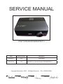
SERVICE MANUAL
P5271/P5290/P5390W/P5271i
Date
Revise Version
Description
2009.08.17
V1.0
Initial Issue
2009.09.16
V2.0
Copyright September, 2009
SI :
TSE:
Add P5271’s extended models: P5390W/P5271i�
All Rights Reserved
P/N: 36.8BV03G001
Check:
Approved:
Preface
This manual is applied to P5271/P5290/P5390W/P5271i projection system. The manual
gives you a brief description of basic technical information to help in service and maintain
the product.
Your customers will appreciate the quick response time when you immediately identify
problems that occur with our products. We expect your customers will appreciate the
service that you offer them.
This manual is for technicians and people who have an electronic background. Please
send the product back to the distributor for repairing and do not attempt to do anything that
is complex or is not mentioned in the troubleshooting.
Note: The information found in this manual is subject to change without prior notice. Any subsequent changes made to the data herein will be incorporated in future edition.
P5271/P5290/P5390W/P5271i Service Manual
Copyright September, 2009
All Rights Reserved
Manual Version 2.0
P5271/P5290/P5390W/P5271i Confidential
i
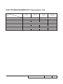
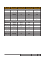
P5271/P5290/P5390W/P5271i Comparison List
Models
Parts
P5271
P5271i
LVPS
75.8BV01GP01
LAMP DRIVER
75.8BW01G002
MAIN BOARD MODULE
70.8BV39GR01
70.8BV47GR01
P5290
P5390W
75.8BV02GP01
70.8EP11GR01
70.8CC18GR01
70.8EP09GR01
70.8CC17GR01
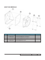
ENGINE MODULE
70.8BV42GR01
70.8CC14GR01
DMD
48.8CQ01G003
48.8EJ01G001
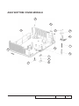
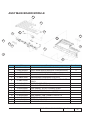
BACK COVER MODULE
70.8BV40GR01
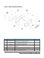
LAMP MODULE
70.8EP10GR01
SP.8BV01GC01
TOP &LAMP COVER MODULE
WIRELESS BOARD
70.8BV46GR01
SP.8EP01GC01
70.8BV45GR01
NA
80.8BV07G001
70.8CC15GR01
70.8CC16GR01
NA
P5271/P5290/P5390W/P5271i Confidential
NA
ii
Table of Content
Chapter 1
Introduction
Highlight
1-1
Compatible Mode
1-4
Product Overview
1-8
Chapter 2 Disassembly Process & Assembly Process
Equipment Needed & Product Overview
2-1
Disassemble Lamp Module
2-2
Disassemble Top/Lamp Cover Module
2-3
Disassemble Keypad Board Module
2-4
Disassemble Main Board Top Shielding
2-4
Disassemble Main Board Module
2-5
Disassemble Front Cover Module
2-8
Disassemble System Fan and Color Wheel Module
2-9
Disassemble Engine Module
2-12
Disassemble DMD Chip and DMD Board
2-12
Disassemble Lamp Driver and Speaker
2-13
Disassemble Blower
2-15
Disassemble LVPS Module
2-15
Disassemble Latch and Spring
2-16
Disassemble Bottom Shielding
2-16
Disassemble Elevator
2-17
Disassemble IO Cover
2-18
Rod Adjustment
2-19
Re-write System and Lamp Usage Hour
2-20
Assemble IO Cover
2-21
Assemble Elevator
2-21
Assemble Bottom Shielding
2-22
P5271/P5290/P5390W/P5271i Confidential
iii
Assemble Latch and Spring
2-23
Assemble LVPS Module
2-23
Assemble Blower
2-24
Assemble Speaker and Lamp Driver Module
2-24
Assemble DMD Chip and DMD Board
2-26
Assemble Engine Module
2-27
Assemble Color Wheel Module and System Fan Module
2-27
Assemble Front Cover Module
2-30
Assemble Main Board Module
2-31
Assemble Main Board Top Shielding
2-32
Assemble Keypad Board Module
2-33
Assemble Top/Lamp Cover Module
2-34
Assemble Lamp Module
2-35
Chapter 3 Troubleshooting
LED Lighting Message
3-1
Main Procedure
3-2
Beep Sound
3-6
Chapter 4 Function Test & Alignment Procedure
Test Equipment Needed
4-1
Introduction of LAN Cable(only for P5271i)
4-1
Service Mode
4-1
OSD Reset
4-1
Test Condition
4-2
Test Inspection Procedure
4-3
PC Mode
4-4
PC Calibration
4-7
Video Performance
4-8
P5271/P5290/P5390W/P5271i Confidential
iv
Optical Performance Measure
4-9
Network Function Test (Only for P5271i)
4-11
Wireless Function Test (Only for P5271i)
4-14
Others
4-17
Chapter 5 Firmware Upgrade Section 1: System Firmware Upgrade
5-1
Equipment Needed
5-1
DLP Composer Lite Setup Procedure
5-2
Get into FW Download Mode
5-4
USB Driver Upgrade Procedure
5-4
Firmware Upgrade Procedure
5-5
Waveform Download
5-8
Restore Fan Speed
5-8
Section 2: Network/Wireless FirmWare Upgrade
5-10
Equipment Needed
5-10
Network/Wireless FW Upgrade Procedure
5-11
Check FW Version
5-12
Chapter 6 EDID Upgrade
EDID Introduction
6-1
Equipment Needed
6-2
Setup Procedure (VGA IN 1 & VGA IN 2)
6-3
EDID Key-In Procedure (VGA)
6-4
Setup Procedure (DVI & HDMI)
6-6
EDID Key-In Procedure (DVI)
6-7
Un-lock SNID and Default Language Reset 6-9
P5271/P5290/P5390W/P5271i Confidential
v
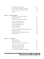
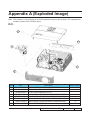
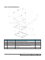
Appendix A
Exploded Overview
I
Appendix B
Serial Number System Definition I
PCBA Code Definition
II
RS232 function command summary table
I
Appendix C
P5271/P5290/P5390W/P5271i Confidential
vi
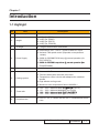
Chapter 1
Introduction
1-1 Highlight
No
Item
1
Dimensions (W x H x D)
● 340.8 x 119.5 x 260.6 mm
2
Weight
● 4060g (for P5271)
● 4185g (for P5290)
● 4190g (for P5271i)
● 4185g (for P5390W)
3
Tilt Angle
● 7 degree with elevator mechanism
4
Power Supply
● Universal AC 100 – 240 V ~ 50-60 Hz with PFC input
● Variance FAN speed control (Depends on temperature
variant)
● 230W for OSRAM E20.8 Lamp @ normal operation (for
P5271/P5271i)
● 280W
�������������������������������������������������������
for OSRAM Lamp driver @ normal operation����������
(for
P5290/P5390W)
5
Keystone correction
● +/ -40 degree
Cooling system
● Advanced Air Flow
● Two fans with system acoustic noise level
● Temperature control circuits with adaptive fan rotational
speeds
● High altitude cooling mode
● Maximum touch temperature follow UL60950-1
7
Throw ratio
● 1.62 – 2.63:1 distance/width ������������
61”���������
@2m (for P5271i)
● 1.61 – 2.63:1 distance/width@60 (for P5290)
● 1.62
��������������������������������������������������
– 2.63:1 distance/width @60” ����������������
(for P5271)
● 1.62 – 2.64:1 distance/width @60” P5390W)
8
Projection lens
● F# 2.41~ 3.2, f= 18.385~29.416 mm, 1.6X Mechanical Zoom
Lens
6
Description
P5271/P5290/P5271i/P5390W/ Confidential
1-
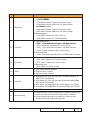
No
Item
Description
Brightness
● Engineering spec:
For P5271i�������
�������������
/P5271:
• 2790 ANSI Lumens (Typical, Full power mode)
• 2500 ANSI Lumens (Minimum, Full power mode)
�������������
For P5290/P5390W:
• 3600 ANSI Lumens (Typical, Full power mode)
• 3200 ANSI Lumens (Minimum, Full power mode)
● Marketing spec:
• 3100 ANSI Lumens (for P5271/P5271i)
• 4000 ANSI Lumens (for P5290/P5390W)
Contrast
● Engineering spec:
•�������������������������������������������������������������
2800 : 1 Full White with full power / full Black with eco
power (Minimum; projection lens at tele mode)
• 3200 : 1 Full White with full power / full Black with eco
power (Typical; projection lens at tele mode)
● Marketing spec:
• 3600: 1 Full White with full power / full Black with eco power
Uniformity
● Engineering spec:
• 65% Japan (Minimum; Full power mode)
• 80% Japan (Typical; Full power mode)
● Marketing spec:
• 80% Japan (Full power mode)
Audio
● One 8-Ohm internal speaker
● Output Power: 2 Watts
● Input sensitivity 0.5Vrms
13
Lamp life
● 1500 hours min, 50% survival rate (Full power Mode) (For
P5271/P5271i/P5390W)
● 2500 hours min, 50% survival rate (Eco power Mode) ������
(For
P5271/P5271i/P5390W)
● 2000 hours Typical@280W (Full power Mode) (For P5290)
● 3000 hours Typical@230W (Eco power Mode) (For P5290)
14
System controller
● TI DDP2431
Lamp housing
● Lamp Assembly could be changed by customer himself, but
should read the user manual for instruction in advance
● Lamp Assembly should be provided by Coretronic and
distributed through authorized agencies
9
10
11
12
15
P5271/P5290/ P5271i/P5390W Confidential
1-
No
Item
16
TI DMD
17
Number of active dots
19
Color wheel
20
Lamp
21
Video compatibility
22
Terminal
Description
● TI DMD 0.55” S450
������������������������������������������
�������������������������������������
2xLVDS XGA Digital Mirror Device
(For
�����������������������
P5271/P5290/P5271i)
● TI
����������������������������������������������������
DMD 0.65” S450 2XLVDS WXGA Digital Mirror Device
(For P5390W)
● 1024 (H) x 768 (V) (����������������������
For P5271/P5290/P5271i)
● 1280(H)
�����������������������������
x 800(V) (�����������
For P5390W)
● 6 segments
● 7200 rpm (2X)
● 9000 rpm@3X PAL 50Hz
● Segment Angle: R81Y41G84C31W52B71
● 230-Watt OSRAM E20.8 Lamp (user replaceable) dimmable
to 190W (for P5271/P5271i)
● 280-Watt OSRAM E20.9 Lamp (user replaceable) dimmable
to 230W (for P5290/�������
P5390W�)
● Standards :
• NTSC (3.58/4.43)
• PAL (B/D/G/H/I/M/N)
• SECAM (B/D/G/K/K1/L)
For MB:
● One 19-pin HDMI
● One DVI-D
● Two D-Sub 15-Pin Female Connector
● One D-Sub 15-Pin output
● One Mini DIN 4-Pin connector for S-Video
● One RCA Jack for Composite Video
● One Mini DIN 3-Pin Connector for RS232
● Two phone jack for line audio input(one package/ two
channel in) (for P5271i)
● Two phone jack for line audio input(same package/ two
channel in) ( for P5390W)
● One phone jack for audio output (for P5271i)
● One phone jack for audio output/One for RF remote (Same
package) (for P5390W)
● One Type-B USB
P5271/P5290/P5390W/P5271i Confidential
1-
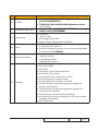
1-2 Compatible Mode
Computer Compatibility
A. VGA Analog
Modes
Resolution
(1) VGA Analog - PC Signal
VGA
640x480
640x480
640x480
640x480
720x400
720x400
SVGA
800x600
800x600
800x600
800x600
800x600
832x624
XGA
1024x768
1024x768
1024x768
1024x768
SXGA
1152x864
1152x864
1152x864
1280x1024
1280x1024
1280x1024
1280x1024
QuadVGA
1280x960
1280x960
SXGA+
1400x1050
UXGA
1600x1200
PowerBook G4
640x480
PowerBook G4
640x480
PowerBook G4
800x600
PowerBook G4
1024x768
PowerBook G4
1152x870
PowerBook G4
1280x960
i Mac DV(G3)
1024x768
V.Frequency [Hz] H.Frequency [KHz]
60
72
75
85
70
85
56
60
72
75
85
75
60
70
75
85
70
75
85
60
72
75
85
60
75
60
60
60
66.6(67)
60
60
75
75
75
31.47
37.86
37.50
43.27
31.47
37.93
35.20
37.88
48.08
46.88
53.67
49.72
48.36
56.48
60.02
68.67
63.80
67.50
77.10
63.98
76.97
79.98
91.15
60.00
75.00
65.32
75.00
31.47
35.00
37.88
48.36
68.68
75.00
60.24
Clock [MHz]
25.18
31.50
31.50
36.00
28.32
35.50
36.00
40.00
50.00
49.50
56.25
57.28
65.00
75.00
78.75
94.50
94.50
108.00
121.50
108.00
134.60
135.00
157.50
108.00
126.00
121.75
162.00
25.17
30.24
40.00
65.00
100.00
126.00
80.00
P5271/P5290/ P5271i/P5390W Confidential
1-
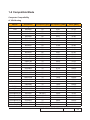
Modes
Resolution
V.Frequency [Hz] H.Frequency [KHz]
(2) VGA Analog - Extended Wide timing
WXGA
1280x768
60
1280x768
75
1280x768
85
1280x720
60
1280x800
60
1440x900
60
1680x1050
60
1366x768
60
1920x1080
60
1024x600
60
(3) VGA Analog -Component Signal
720x480
59.94
480i (NTSC)
(1440x480)
(29.97)
480p (NTSC)
720x480
59.94
720x576
50
576i (PAL)
(1440x576)
(25)
576p (PAL)
720x576
50
720p (NTSC)
1280x720
60
720p (PAL)
1280x720
50
1080i (NTSC)
1920x1080
60(30)
1080i (PAL)
1920x1080
50
1080p (NTSC)
1920x1080
60
1080p (PAL)
1920x1080
50
47.78
60.29
68.63
45.00
49.70
55.94
65.29
47.71
67.50
37.50
Clock [MHz]
79.50
102.25
117.50
74.25
83.50
106.50
146.25
85.50
148.50
50.40
27.00
31.47
27.00
31.25
45.00
37.50
33.75
33.75
67.50
56.26
P5271/P5290/P5390W/P5271i Confidential
1-
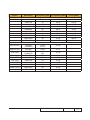
B. HDMI Digital
Modes
Resolution
V.Frequency [Hz] H.Frequency [KHz]
(1) HDMI - PC Signal (same as DVI)
VGA
640x480
640x480
640x480
640x480
720x400
720x400
SVGA
800x600
800x600
800x600
800x600
800x600
832x624
XGA
1024x768
1024x768
1024x768
1024x768
SXGA
1152x864
1152x864
1152x864
1280x1024
1280x1024
1280x1024
1280x1024
QuadVGA
1280x960
1280x960
SXGA+
1400x1050
UXGA
1600x1200
PowerBook G4
640x480
PowerBook G4
640x480
PowerBook G4
800x600
PowerBook G4
1024x768
PowerBook G4
1152x870
PowerBook G4
1280x960
i Mac DV(G3)
1024x768
60
72
75
85
70
85
56
60
72
75
85
75
60
70
75
85
70
75
85
60
70
75
85
60
75
60
60
60
66.6(67)
60
60
75
75
75
31.47
37.86
37.50
43.27
31.47
37.93
35.20
37.88
48.08
46.88
53.67
49.72
48.36
56.48
60.02
68.67
63.80
67.50
77.10
63.98
76.97
79.98
91.15
60.00
75.00
65.32
75.00
31.47
35.00
37.88
48.36
68.68
75.00
60.24
Clock [MHz]
25.18
31.50
31.50
36.00
28.32
35.50
36.00
40.00
50.00
49.50
56.25
57.28
65.00
75.00
78.75
94.50
94.50
108.00
121.50
108.00
134.60
135.00
157.50
108.00
126.00
121.75
162.00
25.17
30.24
40.00
65.00
100.00
126.00
80.00
P5271/P5290/ P5271i/P5390W Confidential
1-
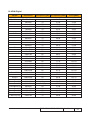
Modes
Resolution
V.Frequency [Hz] H.Frequency [KHz]
(2) HDMI - Extended Wide timing (same as DVI)
WXGA
1280x768
60
1280x768
75
1280x768
85
1280x720
60
1280x800
60
1440x900
60
1680x1050
60
1366x768
60
1920x1080
60
1024x600
60
(3) HDMI - Video Signal
720x480
59.94
480i (NTSC)
(1440x480)
(29.97)
480p (NTSC)
720x480
59.94
720x576
50
576i (PAL)
(1440x576)
(25)
576p (PAL)
720x576
50
720p (NTSC)
1280x720
60
720p (PAL)
1280x720
50
1080i (NTSC)
1920x1080
60(30)
1080i (PAL)
1920x1080
50
1080p (NTSC)
1920x1080
60
1080p (PAL)
1920x1080
50
47.78
60.29
68.63
45.00
49.70
55.94
65.29
47.71
67.50
37.50
Clock [MHz]
79.50
102.25
117.50
74.25
83.50
106.50
146.25
85.50
148.50
50.40
27.00
31.47
27.00
31.25
45.00
37.50
33.75
33.75
67.50
56.26
P5271/P5290/P5390W/P5271i Confidential
1-
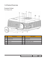
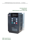
1-3 Product Overview
Projector Outlook
Front /Upper side
Item
Description
Item
Description
1
Lens cap
7
Remote control receivers
2
Elevator button
8
Control panel
3
Elevator foot
9
Power button
4
Zoom Lens
10
Lens shift control rings
5
Zoom ring
11
Tilt adjusting wheel
6
Focus ring
P5271/P5290/ P5271i/P5390W Confidential
1-
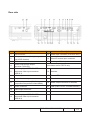
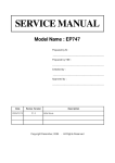
Rear side
Item
Description
Item
Description
1
USB connector
13
Audio input connector (VGA IN 2/ DVI)
2
DVI input connector (for digital signal
with HDCP function)
14
Wired IR remote input connector
3
HDMI connector
15
Kensington™ lock port
4
5
Monitor loop-through output
connector (VGA-Out)
PC analog signal/HDTV/SCART/
component video input connector
(VGA IN 1)
Below items are for P5271i only:
16
Antenna
6
S-Video input connector
17
Power LED for wireless
7
Composite video input connector
18
Reset button
8
Audio input connector (VGA IN 1/
Component/Composite/S-Video/HDMI)
19
Audio output connector for wireless
9
RS232 connector
20
LAN (RJ45 Port for 10/100M Ethernet)
10
Audio output connector
11
Power socket
12
PC analog signal/HDTV/SCART/
component video input connector
(VGA IN 2)
P5271/P5290/P5390W/P5271i Confidential
1-
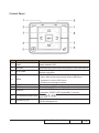
Control Panel
Item
Function
1
LAMP
2
RESYNC
3
4
5
6
7
8
9
Description
Lamp Indicator LED
Automatically synchronizes the projector to the input source.
Adjusts the image to compensate for distortion caused by
KEYSTONE
tilting the projector.
• Press “MENU” to launch the Onscreen display (OSD)
menu, back to the previous step for the OSD menu
MENU
operation or exit the OSD menu.
• Confirm your selection of items.
POWER
See the contents in “Turning the Projector On/Off” section.
TEMP
Temp Indicator LED
Press “SOURCE” to choose RGB, Component, SVideo,
SOURCE
Composite, SCART, HDTV and HDMI™ sources.
Use to
select items or make adjustments to
Four directional select keys
your selection.
Unique Acer functions: eOpening, eView, eTimer,
Empowering key
ePower Management.
P5271/P5290/ P5271i/P5390W Confidential
1-10
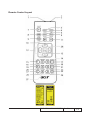
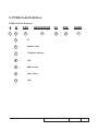
Remote Control Layout
P5271/P5290/P5390W/P5271i Confidential
1-11
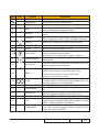
Item
Icon
Function
Description
1
Infrared transmitter
Sends signals to the projector.
2
Laser pointer
Aim the remote at the viewing screen.
3
FREEZE
4
HIDE
5
RESYNC
6
SOURCE
To pause the screen image.
Momentarily turns off the video. Press “HIDE” to hide the
image, press again to display the image.
Automatically synchronizes the projector to the input
source.
Press “SOURCE” to choose from RGB, Component, SVideo, Composite, SCART, HDTV and HDMI™ sources.
7
POWER
Refer to the “Turning the Projector On/Off” section.
8
ASPECT RATIO
To choose the desired aspect ratio (Auto/4:3/16:9)
9
ZOOM
Zooms the projector display in or out.
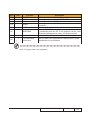
10
Laser button
11
Empowering key
12
KEYSTONE
13
MENU
14
PAGE
15
RGB
16
BRIGHTNESS
17
CONTRAST
18
COLOR
19
VGA
20
COMPONENT
Aim the remote at the viewing screen, press and hold this
button to activate the laser pointer.
This function is not supported in Japanese market.
Unique Acer functions: eOpening, eView, eTimer, ePower
Management.
Adjusts the image to compensate for distortion caused by
tilting the projector (± 40 degrees).
• Press “MENU” to launch the Onscreen display
(OSD) menu, back to the previous step for the
OSD menu operation or exit the OSD menu.
• Confirm your selection of items.
For computer mode only. Use this button to select the next
or previous page. This function is only available when connected to a computer via a USB cable.
Press “RGB” for true-color optimization.
Press “BRIGHTNESS” to adjust the brightness of the image.
Use the “CONTRAST” option to control the difference between the lightest and darkest parts of the picture.
Press “COLOR” to adjust the color temperature of image.
Press “VGA” to change source to the VGA connector. This
connector supports analog RGB, YPbPr (480p/576p/720p/
1080i), YCbCr (480i/576i) and RGBsync.
Press “COMPONENT” to change source to Component
video. This connection supports YPbPr (480p/576p/720p/
1080i) and YCbCr (480i/576i).
P5271/P5290/ P5271i/P5390W Confidential
1-12
Item
Icon
Function
Description
21
22
23
S-VIDEO
VIDEO
DVI
24
HDMI™
25
MUTE
26
WIRELESS
27
KeyPad 0~9
To change source to S-Video.
To change source to COMPOSITE VIDEO.
To change source to DVI-D.
To change source to HDMI™. (for the model if with HDMI™
connector)
To turn on/off the volume.
Press “WIRELESS” to display the image which is wirelessly transmitted from the PC to the projector via the “Acer
eProjection Management” utility. (for wireless model)
Press “0~9” to input a password in the “Security”.
28
Four directional
select keys
Use up, down, left, right buttons to select items or make
adjustments to your selection.
Note: “#” Japan area is not supported.
P5271/P5290/P5390W/P5271i Confidential
1-13
Getting Started
Connecting the Projector
Item
Description
Item
Description
1
Power cord
8
DVI cable
2
3
4
5
6
7
VGA cable
Composite video cable
USB cable
VGA to component/HDTV adapter
S-Video cable
Audio cable jack/jack
9
10
11
12
13
14
HDMI cable
3 RCA component cable
RS232 cable
Audio cable Jack/RCA
LAN Cable
Audio cable jack for wired remote
Note: To ensure the projector works well with your computer, please make sure the timing of the display mode is compatible with the projector.
P5271/P5290/ P5271i/P5390W Confidential
1-14
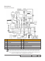
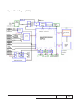
System Block Diagram (P5271)
P5271/P5290/P5390W/P5271i Confidential
1-15
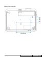
Bottom Cover Dimension
P5271/P5290/ P5271i/P5390W Confidential
1-16
Chapter 2
Disassembly & Assembly Process
2-1 Equipment Needed & Product Overview
1. Screw Bit (+): 105
2. Screw Bit (+): 107
3. Screw Bit (-): 107
4. Hex Sleeves 5mm
5. Long Nose Nipper
6. Tweezers
7. Projector
* Before you start: This process is protective level II. Operators should wear electrostatic chains.
* Note: - If you need to replace the Main Board, you have to get into Service Mode and record the lamp usage hour, please refer to section 2-19.
- As the process of P5290/P5390W/P5271i disassembling is the same as P5271, we take P5271 for example here.
P5271/P5290/P5390W/P5271i Confidential
2-
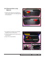
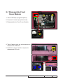
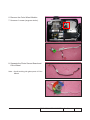
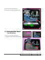
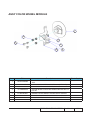
2-2 Disassemble Lamp
Module
1. Push the two clips (as red square) as yellow arrows point on the left/right side of the projector.
Left side of projector
Right side of projector
2. Pull upword the Lamp Cover Module slightly (as blue arrows point).
3. Loosen 3 screws (as red circle) on the Lamp Module.
4. Take off the Lamp Module.
P5271/P5290/P5390W/P5271i Confidential
2-
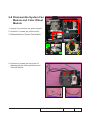
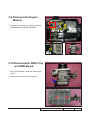
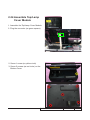
2-3 Disassemble Top/Lamp
Cover Module
1. Unscrew 5 screws (as red circle) from the
Bottom Cover.
2. Unscrew 1 screw (as yellow circle)
Note: - When you disassemble the Top/Lamp Cover, take care the FPC cable which connect Main Board and Keypad Board Module, please unplug the connector (as green square) from Keypad Board Module.
3. Disassemble the Top/Lamp Cover Module.
P5271/P5290/P5390W/P5271i Confidential
2-
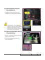
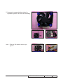
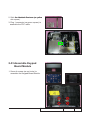
2-4 Disassemble Keypad
Board Module
1. Unscrew 4 screws (as red circle) to disassemble the Keypad Board Module.
NOTE: Circuit boards > 10 cm² has been highlighted with the yellow rectangle
as above image shows. Please detach the Circuit boards and follow local regulations for disposal.
Keypad Board
Keypad
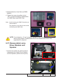
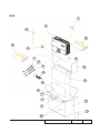
2-5 Disassemble Main Board
Top Shielding
1. Unplug 1 connector (as green square) to remove the FPC cable.
2. Tear off the Heatsink Aluminum (as yellow dot square).
FPC Cable
Heatsink Aluminum
P5271/P5290/P5390W/P5271i Confidential
2-
3. Unscrew 5 screws (as red circle) to disassemble the Main Board Top Shielding.
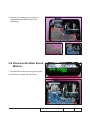
2-6 Disassemble Main Board
Module
1. Unscrew 8 hex screws (as green circle).
2. Unscrew 2 screws (as red circle).
P5271/P5290/P5390W/P5271i Confidential
2-
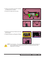
3. Remove 2 Main Board Shielding Bottom Bracket (as red arrows point).
4. Cut off the cable tie (as green square).
5. Unplug 2 connectors (as purple square) to disassemble the Color Wheel cable and Lamp Driver to Main Board cable.
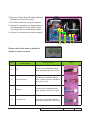
6. Unplug 6 connectors (as yellow square).
A B
CD
E
F
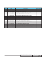
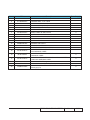
Please refer to the table as below for
details of each connector
Bracket
Male Connector
on Main Board
Item
The key feature
A
IR
Compose of Red/Black/Yellow
Wire and Black wire tube (3 pin)
B
Photo Sensor
Compose of Red/White/Black
Wire , Red Connector and Black
wire tube (3 pin)
C
Blower
Compose of Red/Black/White
Wire and Blue wire tube (3 pin)
D
System Fan
Compose of Red/Yellow/Black
Wire and Green wire tube (3 pin)
Figure
P5271/P5290/P5390W/P5271i Confidential
2-
Item
Male Connector
on Main Board
The key feature
E
Lamp Driver
Black wire tube (5 pin)
F
Speaker
Compose of Yellow/White Wire
and Black wire tube (2 pin)
Figure
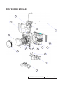
7. Disassemble the Main Board Module.
8. Tear off 2 EMI tapes (as blue square) to separate Main Board Module and Main Board Bottom Shielding.
NOTE: Circuit boards > 10 cm² has been highlighted with the yellow rectangle as above image shows. Please detach the Circuit boards and follow local regulations for disposal.
P5271/P5290/P5390W/P5271i Confidential
2-
2-7 Disassemble Front
Cover Module
1. Tear off 3M tape (as green square).
2. Unscrew 3 screws (as yellow circle).
3. Disassemble the Front Cover Module.
4. Tear off black mylar (as yellow square) to disassemble IR Board.
5. Unfasten 2 tenons (as blue square) to disassemble IR Lens.
IR Board
IR Lens
P5271/P5290/P5390W/P5271i Confidential
2-
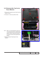
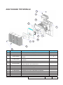
2-8 Disassemble System Fan
Module and Color Wheel
Module
1. Unplug 2 connectors (as green square).
2. Unscrew 7 screws (as yellow circle).
3. Disassemble the System Fan Module.
4. Unscrew 3 screws (as red circle) to disassemble the Interrupt Switch and Thermal Switch.
Interrupt Switch
Thermal Switch
P5271/P5290/P5390W/P5271i Confidential
2-
5. Unscrew 4 screws (as blue circle) to separate System Fan and Fan Shielding.
Note: - Take the Fan Module as the right gesture.
System Fan
Fan Shielding
the right gesture
the wrong gesture
P5271/P5290/P5390W/P5271i Confidential
2-10
6. Remove the Color Wheel Module.
7. Unscrew 1 screw (as green circle).
8. Separate the Photo Sensor Board and Color Wheel.
Note: - Avoid touching the glass parts of Color Wheel.
P5271/P5290/P5390W/P5271i Confidential
2-11
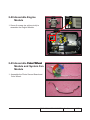
2-9 Disassemble Engine
Module
1. Unscrew 6 screws (as yellow circle) to disassemble the Engine Module.
2-10 Disassemble DMD Chip and DMD Board
1. Tear off the black mylar (as blue arrow point).
2. Unscrew 2 screws (as red circle).
P5271/P5290/P5390W/P5271i Confidential
2-12
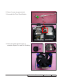
3. Disassemble the Heat Sink and DMD Module.
4. Rotate the screw (as yellow circle)
180° counterclockwise to disassemble
the DMD Board and DMD Chip.
Note: - Avoid touching the DMD Chip when you disassemble it.
- Pay attention to the fixed position when assembling the DMD Chip.
NOTE: Circuit boards > 10 cm² has been highlighted with the yellow rectangle as above image shows. Please detach the Circuit boards and follow local regulations for disposal.
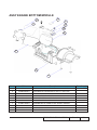
2-11 Disassemble Lamp Driver Module and Speaker
1. Unscrew 4 screws (as yellow circle) to disassemble the Lamp Driver Module and the Speaker (as blue arrow point).
P5271/P5290/P5390W/P5271i Confidential
2-13
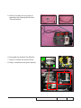
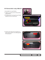
2. Unplug 3 connectors (as green square) to disassemble the cables.
3. Unscrew 4 screws (as red circle). 4. Separate Lamp Driver Module and Lamp Driver Holder.
5. Separate Speaker and Speaker Rubber.
Lamp Driver Holder
NOTE: Circuit boards > 10 cm² has been highlighted with the yellow rectangle as above image shows. Please detach the Circuit boards and follow local regulations for disposal.
P5271/P5290/P5390W/P5271i Confidential
2-14
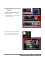
2-12 Disassemble Blower
1. Unscrew 3 screws (as green circle) to disassemble the Blower Module.
2-13 Disassemble LVPS Module
1. Unscrew 7 screws (as red circle) to disassemble the LVPS Module.
2. Unplug 1 connector (as green square).
3. Remove the cable and the AC Inlet Bracket from LVPS Module.
NOTE: Circuit boards > 10 cm² has been highlighted with the yellow rectangle as above image shows. Please detach the Circuit boards and follow local regulations for disposal.
AC Inlet Bracket
P5271/P5290/P5390W/P5271i Confidential
2-15
2-14 Disassemble Latch and Spring
1. Take out 2 springs on each side to disassemble 2 latches (as green square).
Latches and Springs
2-15 Disassemble Bottom Shielding
1. Unscrew 5 screws (as red cricle) to disassemble Bottom Shielding and Lamp Connector Holder.
Lamp Connector Holder
P5271/P5290/P5390W/P5271i Confidential
2-16
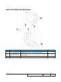
2-16 Disassemble Elevator
1. Unscrew 1 screw (as red cricle) on the backside of Bottom Cover.
2. Unscrew 2 screws (as yellow cricle) on the inside of Bottom Cover.
3. Disassemble the Elevator Foot, Elevator Bracket and Elevator Push Button.
Elevator Bracket
Elevator Foot
Elevator Push Button
P5271/P5290/P5390W/P5271i Confidential
2-17
2-17 Disassemble IO Cover
1. Unfasten 2 tenons (as green square) to
disassemble IO Cover.
P5271/P5290/P5390W/P5271i Confidential
2-18
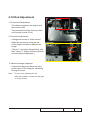
2-18 Rod Adjustment
1. Environment Adjustment
- The distance between the engine and
the screen is 2M.
- This process should be done at a dark
environment (under 2 Lux).
2. Procedure Adjustment
- Change
the screen to "white screen".
- Adjust the screws by using the rod
on the engine module to readjust the
image.
("Screw 1" should be adjusted first, and then "screw 2". Adjust until the yellowish
or bluish parts disappeared.)
screw 2
screw 1
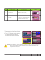
3. Abnormal image inspection
- It should not have any abnormal color
at the frame of the image by estimating
through the eyes.
Note: - To avoid over adjusting the rod.
- After the opreation, please use the glue
to fix the screws.
P5271/P5290/P5390W/P5271i Confidential
2-19
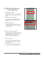
2-19 Re-write System and
Lamp Usage Hour
1. Get into Service Mode
- Press "Power", "Left", "Left" and "Menu" buttons sequentially to get into Service Mode.
2. Get into Other Settings Mode
- Use "Up" or "Down" buttons to select "Other Settings", then press "Menu" button.
3. Re-write System Hours
- Select "System Hours Adjust" and use "Left" or "Right" buttons to re-write the "System Hours".
4. Re-write Lamp Hours (full/low)
- Select "Lamp Hours Adjust (full)"/"Lamp Hours Adjust (low)" and use "Left" or "Right" buttons to re-write the "Lamp Hours (full)"/"Lamp Hours (low)".
5. Exit Service Mode
- Use "Up" or "Down" buttons to select "Exit", press "Menu" button to exit the Service Mode.
Note: left key = decrease System/Lamp hour
right key =increase System/Lamp hour
P5271/P5290/P5390W/P5271i Confidential
2-20
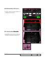
2-20 Assemble IO Cover
1. Fasten 2 tenons (as green square) to assemble the IO Cover.
2-21 Assemble ��������
Elevator
1. Assemble the Elevator Foot, Elevator Bracket and Elevator Push Button.
P5271/P5290/P5390W/P5271i Confidential
2-21
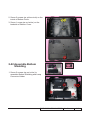
2. Screw 2 screws (as yellow circle) on the inside of Bottom Cover.
3. Screw 1 screw (as red cricle) on the backside of Bottom Cover.
2-22 Assemble Bottom Shielding
1. Screw 5 screws (as red cricle) to assemble Bottom Shielding and Lamp Connector Holder.
P5271/P5290/P5390W/P5271i Confidential
2-22
2-23 Assemble Latch and
Spring
1. Fix 2 springs on each side to assemble 2 latches (as green square).
2-24 Assemble LVPS Module
1. Assemble the cable and the AC Inlet Bracket.
2. Plug 1 connector (as green square).
3. Screw 7 screws (as red circle) to assemble the LVPS Module.
P5271/P5290/P5390W/P5271i Confidential
2-23
2-25 Assemble Blower
1. Screw 3 screws (as green circle) to assemble the Blower Module.
2-26 Assemble Speaker and Lamp Driver Module
1. Assemble Speaker and Speaker Rubber.
2. Assemble Lamp Driver Module and Lamp Driver Holder.
P5271/P5290/P5390W/P5271i Confidential
2-24
3. Screw 4 screws (as red circle).
4. Plug 3 connectors (as green square) to assemble the cables.
5. Screw 4 screws (as yellow circle) to assemble the Lamp Driver Module and the Speaker (as blue arrow point).
P5271/P5290/P5390W/P5271i Confidential
2-25
2-27 Assemble DMD Chip and DMD Board
1. Rotate the screw (as yellow circle)
180° clockwise to assemble the DMD Board and DMD Chip.
2. Assemble the Heat Sink and DMD Module.
3. Screw 2 screws (as red circle).
4. Stick black mylar (as blue arrow point).
P5271/P5290/P5390W/P5271i Confidential
2-26
2-28 Assemble Engine Module
1. Screw 6 screws (as yellow circle) to assemble the Engine Module.
2-29 Assemble �������������
Color Wheel Module and System Fan Module
1. Assemble the Photo Sensor Board and Color Wheel.
P5271/P5290/P5390W/P5271i Confidential
2-27
2. Screw 1 screw (as green circle).
3. Assemble the Color Wheel Module.
4. Screw 4 screws (as blue circle) to assemble System Fan and Fan Shielding
P5271/P5290/P5390W/P5271i Confidential
2-28
5. Screw 3 screws (as red circle) to assemble the Interrupt Switch and Thermal Switch.
6. Assemble the System Fan Module.
7. Screw 7 screws (as yellow circle).
8. Plug 2 connectors (as green square).
P5271/P5290/P5390W/P5271i Confidential
2-29
2-30 Assemble Front Cover
Module
1. Fasten
������������������������������������������
2 tenons (as blue square) to assemble IR Lens.
2. Stick black mylar (as yellow square) to assemble IR Board.
3. Assemble the Front Cover Module.
4. Screw 3 screws (as yellow circle).
5. Stick 3M tape (as green square).
P5271/P5290/P5390W/P5271i Confidential
2-30
2-31 Assemble Main Board Module
1. Stick 2 EMI tapes (as blue square) to
assemble Main Board and Main Board Bottom Shielding.
2. Assemble the Main Board Module.
3. Plug
�������������������������������������
6 connectors (as yellow square).
4. Plug 2 connectors (as purple square) to assemble the Color Wheel cable and Lamp Driver to Main Board cable.
5. Tie the cables with cable tie �����������
(as green square).
6. Assemble 2 Main Board Bottom Shielding Brackets (as red arrows point).
P5271/P5290/P5390W/P5271i Confidential
2-31
7. Screw 2 screws (as red circle).
8. Screw 8 hex screws (as green circle).
2-32 ���������������������
Assemble Main Board Top Shielding
1. Screw 5 screws (as red circle) to assemble the Main Board Top Shielding. P5271/P5290/P5390W/P5271i Confidential
2-32
2. Stick the
����������������������������������
Heatsink Aluminum (as yellow dot square).
3. Plug 1 connector (as green square) to assemble the FPC cable.
2-33 Assemble Keypad Board Module
1. Screw 4 screws (as red circle) to assemble the Keypad Board Module.
P5271/P5290/P5390W/P5271i Confidential
2-33
2-34 Assemble Top/Lamp Cover Module
1. Assemble the Top/Lamp Cover Module.
2. Plug the connector (as green square).
2. Screw 1 screw (as yellow circle)
3. Screw 5 screws (as red circle) on the Bottom Cover.
P5271/P5290/P5390W/P5271i Confidential
2-34
2-35 Assemble Lamp Module
1. Assemble the Lamp Module.
2. Tighten 3 screws (as red circle) on the Lamp Module.
3. Pull downword the Lamp Cover Module slightly (as blue arrows point).
4. Push the two clips (as red square) as yellow arrows point on the left/right side of the projector.
P5271/P5290/P5390W/P5271i Confidential
2-35
Chapter 3
Troubleshooting
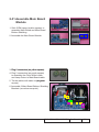
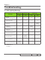
3-1 LED Lighting Message
Lamp LED
Temp Led
Red
Red
Red
Blue
Standby
(power cord plugged in)
--
--
V
--
Power button ON
--
--
--
V
Lamp retry
--
--
--
Quick
flashing
Turning off
(cooling state)
--
--
Quick
flashing
--
Turning off
(cooling completed)
--
--
V
--
Error (thermal failure)
--
V
--
V
Error (fan failure)
--
Quick
flashing
--
V
Error (lamp failure)
V
--
--
V
Quick
flashing
--
--
V
Message
Error (color Wheel failure)
Power LED
Note: Steady Light: "V"
No Light: "--"
P5271/P5290/P5390W/P5271i Confidential
3-
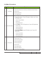
3-2 Main Procedure
No
Symptom
Procedure
- Ensure the Power Cord and AC Power Outlet are securely connected
- Ensure all connectors are securely connected and aren’t broken
1
No Power
- Check LVPS
- Check Lamp Driver
- Check Main Board
- Check LED Status
a. Thermal/Fan Failure: Temp LED (lights or flashes red), Power
LED (lights red)
- Check Thermal Switch
- Check Fan
- Check Main Board
b. Lamp Failure:
������� Lamp LED (lights red), Power LED (lights blue)
2
Auto Shut Down
- Check Lamp
- Check Lamp Driver
- Check Main Board
c. Color
���������������������
Wheel ���������
Failure��: Lamp LED (flashes red), Power LED
(lights blue)
- Check Color Wheel
- Check Photo Senor
- Check Main Board
- Ensure all connectors are securely connected and aren’t broken
- Check Lamp Cover
- Check Interrupt Switch
- Check Lamp Module
3
No Light On
- Check Lamp Driver
- Check LVPS
- Check Main Board
- Check Color Wheel
- Check Photo Sensor Board
P5271/P5290/P5390W/P5271i Confidential
3-
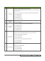
No
Symptom
Procedure
- Ensure the Signal Cable and Source work
(If you connect multiple sources at the same time, use the "Source"
button switch)
- Ensure all connectors are securely connected and aren’t broken
4
No Image
- Check Main Board
- Check DMD Board
- Check DMD Chip
- Check Engine Module
5
Mechanical
Noise
- Check Color Wheel
- Check Fan Module
- Check if the Main Board and the DMD Board are
assembled properly
6
Line Bar/Line
Defect
- Check Main Board
- Check DMD Board
- Check DMD Chip
- Do "Reset (All data)" of the OSD Menu
- Ensure that the signal cables and source are work as well
- Check Lamp Driver and waveform
7
Image Flicker
- Check Lamp Module
- Check Color Wheel
- Check Photo Sensor and clean Photo Sensor
- Check DMD Board
- Check Main Board
- Do "Reset (All data)" of the OSD Menu
- Adjust Color Wheel Index
8
Color Abnormal
- Check Main Board
- Check DMD Board
- Check Color Wheel
P5271/P5290/P5390W/P5271i Confidential
3-
No
Symptom
Procedure
- Ensure the projection screen without dirt
- Ensure the projection lens is clean
9
Poor Uniformity/
Shadow
- Ensure the Brightness is within spec
- Check rod alignment
- Check Engine Module
- Ensure the projection screen without dirt
- Ensure the projection lens is clean
10
Dead Pixel/Dust
(Out of spec.)
- Clean DMD Chip and Engine Module
- Check DMD Chip
- Check Engine Module
- Ensure that the signal cables and source work as well
11
Garbage Image
- Check Main Board
- Check DMD Board
- Remote Controller
a. Check Battery
b. Check Remote Controller
c. IR receiver
12
Remote Controller/Control
Panel Failed
d. Check IR Sensor Board
e. Check Main Board
- Control Panel
a. Check FPC
b. Check Keypad Board
c. Check Main Board
13
Function Abnormal
- Do "Reset (All data)" of the OSD Menu
- Check Main Board
- Ensure that the signal cables and source are work as well
14
Audio Abnormal
- Ensure that your Projector is not in “Mute” mode
- Check Main Board
- Check Speaker
P5271/P5290/P5390W/P5271i Confidential
3-
No
Symptom
Procedure
- An unique Universal Password which is printed on the
Security Card. This unique password is a back door of
Administrator Password which will be accepted by projector
anytime no matter what the Administrator Password is.
- If you forget the Password, please do the following steps to get
the Universal Password:
(1) Click the "AcerSNID"
(2) Input SNID number. (SNID number is on the Security Card)
15
Forgetting Password (administrator Password)
(3) Click "Calculate". Then the Universal Password will appear.
16
Universal Password Failure
- Please confirm whether the SNID number of Service Mode
is the same as the SNID number on the backside of projector?
- If not, please do the actions as below:
a. Execute the EDID Upgrade Procedure (refer to Chapter 6)
b. Execute "Un-lock SNID and Default Language Reset" (refer
to 6-7 of Chapter 6)
c. Press "Power", "Left", "Left" and "Menu" buttons sequentially
to get into Service Mode to obtain the SNID number, then calculate
the Universal Password.
P5271/P5290/P5390W/P5271i Confidential
3-
No
Symptom
Procedure
- Ensure you use the right LAN cable.
17
- Ensure RJ45 Connector work well (after joining RJ45 line, Green
LED and Red LED of RJ45 Port will light).
Network Function Abnormal
(only for P5271i)
- Check Internet Source and Wireless Module if LED message is in
abnormal status.
- Check Main Board if LED message is in normal status.
- Ensure setting on projector and PC (Laptop) are correct.
18
- Ensure the signal strength of wireless network connection is
good enough.
Wireless Function Abnormal
(only for P5271i)
- Check Wireless Module
- Check Main Board
3-3 Beep Sound
No
1
Scenario
Beep sound definition
Power on (as soon as power button pressed) So(0.3s)
2 x {So(0.1s) – Off(0.1s)} per lighting failure
12s interval for each trial lighting. Max 4
times of trial
2 x {So(0.1s) – Off(0.1s)} periodically per 3
seconds, Totally 5 cycles. Turn off projector
after 5 cycles.
2 x {So(0.1s) – Off(0.1s)} periodically per 3
seconds, Totally 5 cycles. Turn off projector
after 5 cycles.
2
Power on (lamp lighting failed)
3
Power on (lens cap was not opened, for the
model with sliding lens cover only)
4
Close lens cap while projector is operating
(for the model with sliding lens cover only)
5
Power off (power button pressed twice)
So(0.3s)
6
Fan lock
So(0.1s) periodically per second
7
Overheat
8
Lamp error
9
Lamp Life reminding
10
Presentation Timer (time is up)
2 x {So(0.1s) – Off(0.1s)} periodically per
second
3 x {So(0.1s) – Off(0.1s)} periodically per
second
3 x {Do(0.2s) – Off(0.8s) – So(0.2s)
– Off(0.8s)} with reminding message
3 x {Do(0.1s) – Off(0.9s)} - So(0.5s)
P5271/P5290/P5390W/P5271i Confidential
3-
Chapter 4
Function Test & Alignment Procedure
4-1 Test Equipment Needed
- IBM PC with SVGA/XGA resolution
- DVD player with Multi-system, equipped "Component", "S-Video","Composite" and "HDMI".
- HDTV Source (480P, 720P, 1080i, 1080P)
- Minolta CL-100
- Quantum Data 802B or CHROMA2327 (Color Video Signal & Pattern Generator)
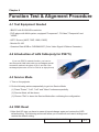
4-2 Introduction of LAN Cable(only for P5271i)
If you use P5271i network function, you have to
use the special LAN cable with one end adopts special
connection method: the wires of Pin 2 and Pin 6 are exchanged.(the order of Pin1 to Pin8 is as right picture)
Pin1
---->
Pin8
4-3 Service Mode
1. Turn on the projector
2. Do the following actions sequentially to get into Service Mode
(1) Press "Power", "Left", "Left" and "Menu" buttons sequentially.
(2) Service Mode will be shown.
(3) Choose "Exit" to leave the Service Mode after confirming the configuration.
4-4 OSD Reset
1. After final QC step, we have to erase all saved change again and restore the OSD
default setting. The following actions will allow you to erase all end-users' settings and
restore the default setting:
P5271/P5290/P5390W/P5271i Confidential
4-
(1) Please get into OSD menu.
(2) To execute "Reset" function.
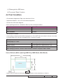
4-5 Test Condition
- Circumstance brightness: Dark room less than 2.0 lux.
- Inspection distance: 1.8 m~2.5 m functional inspection.
- Screen size: 60 inches diagonal.
- After repairing each unit, it should be Run-in (refer to the below table).
Symptom
Normal repair
NFF
Auto shutdown
Run-in Time
2 hours
4 hours
6 hours
- Get into Burn-In Mode
* Cycle setting is based on the defect symptoms. ie: If it is NFF, the run-in time is 4 hours. You have
to set the lamp on for 50 min. and lamp off for 10 min for 4 cycles.
Press power→ left → left → menu
Choose Burn In > enter
Lamp On (Min)
Press right key to adjust the time (50)
Lamp Off (Min)
Press right key to adjust the time (10)
Set Burning cycle
Press right key to adjust the cycle
After setting up the time, choose ''Enter into Burn In Mode'' and press "Menu" button.
Screen Defects (While replacing DMD Chip, DMD Board, Main Board)
Frame
< Figure: Zone A, Zone B & Frame (as green line) Definition, Active area=Zone A+ Zone B >
P5271/P5290/P5390W/P5271i Confidential
4-
Defect specification table
Order
1
Symptom
Bright pixel (dots)
Pattern
Gray 10 pattern
Criteria
A+B≤1
2
Dark pixel (dots)
White pattern
A+B ≤ 6
3
Bright blemish
Gray 15 pattern
A+B ≤ 10
4
Dark blemish
Blue 60 pattern
A+B ≤ 10
5
Bright dot on frame
Gray 10 pattern
≤1
6
Unstable pixel
White & Black pattern
A+B ≤ 1
7
Adjacent dark pixel
White & Black pattern
A+B = 0
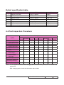
4-6 Test Inspection Procedure
Change parts
Update
Color
Lamp Engine
Main
Firmware
EDID
Wheel Module Module
Board
Version Update
v
Color Wheel Index
v
PC Calibration
v
v
Lamp
Blower
v
v
v
Reset Lamp Hour
v
OSD Reset
v
EDID
v
Re-write Lamp
Hour Usage
v
Reset Default
Language
v
v
v
v
Rod adjustment
v
Waveform Download
(for P5271/P5271i)
Restore Blower Speed
Lamp
Driver
v
v
v
v
Note: - If Color appears abnormal after changing Main Board Module, please do Color Wheel index adjustment.
- After changing parts, check the information above table.
P5271/P5290/P5390W/P5271i Confidential
4-
4-7 PC MODE
Note: - When getting into function test, adjust "lens shift" to guarantee the lens at the highest state and the image maximum, and adjust the focus to guarantee the image at the clearest, then start test.
1. Frequency and Tracking Boundary
Procedure
- Test equipment: video generator
- Test signal: analog 1024 x 768@60Hz (for P5271/P5290/P5271i);
1280 x800@75H (for P5390W)
- Test Pattern: General-1 or Master
- Check and see if the image sharpness is well
performed.
General-1
- If not, re-adjust by the following steps:
(1) Select "Frequency" function to adjust the total
pixel number of pixel clock in one line period.
(2) Select "Tracking" function and use right or
left arrow key to adjust the value to minimize
video flicker.
- Adjust Resync or Frequency/Tracking/H. Position/V. Position to the inner screen.
Inspection item
- Eliminate visual wavy noise by Resync,
Frequency or Tracking selection.
- Check if there is noise on the screen.
- Horizontal and vertical position of the video
should be adjustable to the screen frame.
Criteria
- If there is noise on the screen, the product is
considered as failure product.
- If there is noise on the screen, use auto or manual "frequency" function or "tracking" function to
adjust the screen.
- The PC mode functionally sure be workable
include support format with frequency and auto
detected functional will be workable.
Master
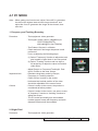
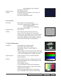
2. Bright Pixel
Procedure - Test equipment: video generator
P5271/P5290/P5390W/P5271i Confidential
4-
- Test signal: analog 1024 x 768@60Hz (for P5271/P5290���������
/P5271i��
);
1280 x800@75H (for P5390W)
- Test Pattern: Gray 10
Inspection item
- Bright pixel check.
Criteria
- Bright pixel should be no more than 1 under gray 10 pattern.
- Adjacent pixels are unacceptable.
- Ref. Defect specification table
Gray 10
3. Dark Pixel
Procedure - Test equipment: video generator
- Test signal: analog 1024 x 768@60Hz (for P5271/P5290/P5271i);
1280 x800@75H (for P5390W)
- Test Pattern: Full white
Inspection item
- Dark pixels check.
Criteria
- The dark pixel should be no more than 6 under full white pattern.
- Adjacent pixels are unacceptable.
- Ref. Defect specification table
Full white
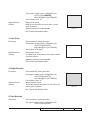
4. Bright Blemish
Procedure
- Test equipment: video generator
- Test signal: analog 1024 x 768@60Hz (for P5271/P5290/P5271i);
1280 x800@75H (for P5390W)
- Test Pattern: Gray 15
Inspection item
- Bright blemish check.
Criteria
- The bright blemish should be no more than 10 under gray 15 pattern.
Gray 15
- Ref. Defect specification table
5. Dark Blemish
Procedure
- Test equipment: video generator
- Test signal: analog 1024 x 768@60Hz (for P5271/P5290/P5271i);
P5271/P5290/P5390W/P5271i Confidential
4-
1280 x800@75H (for P5390W)
- Test Pattern: Blue 60
Inspection item
- Dark blemish check.
Criteria
- The dark blemish should be no more than 10 under blue 60 pattern.
- Ref. Defect specification table
Blue 60
6. Focus Test
Procedure - Test equipment: video generator
- Test signal: analog 1024 x 768@60Hz (for P5271/P5290/P5271i);
1280 x800@75H (for P5390W)
- Test Pattern: Full screen
Inspection item
- Focus check
Criteria
-From screen 2 M via visual to check the
focus, look at the entire screen, focus shall
be clear, crisp, and sharp over the entire surface of the display pattern. (Blur word on one of the corner after adjustment is acceptable. However, the word should at least be recognizable.)
Full screen
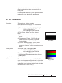
7. Color Performance
Procedure
- Test equipment: video generator.
- Test signal: 480p, 720p, 1080p
- Test Pattern: Master, 64 gray RGBW or
SMPTE bar
* Please refer to 4-2 to get into service mode. Use
720p & 1080p signal, master pattern to do HDTV
test. Color cannot discolor to purple and blue.
Inspection item
- Check if each color level is well-functioned.
- Color saturation
Criteria
- Screen appears normal. It should not have any
abnormal condition, such as lines appear on the
screen and so on.
- Color appears normal.
- It is unacceptable to have few lines flashing.
- RGBW should all appear normal on the screen
and sort from R -G-B-W.
- Color levels should be sufficient and normal.
(The unidentified color levels on both left and
Master
64 gray RGBW
SMPTE BAR
P5271/P5290/P5390W/P5271i Confidential
4-
right sides should not over 4 color levels.)
- Gray level should not have abnormal color or
heavy lines.
- If color appears abnormal, please get into service
mode to do color wheel index adjustment.
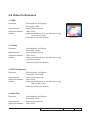
4-8 PC Calibration
Procedure
- Test equipment: video generator
- Once Main Board is changed. PC Calibration should be done as well.
(1) Test signal analog: 1024 x 768 @60Hz �������
(for P5271/P5290/P5271i);
1280 x800@75H (for P5390W)
(2) Test Pattern: White (up) Black (down)
- Note
(1) Calibration pattern should be in full screen mode.
(2) Please press "Power", "Left", "Left" and "Menu" buttons sequentially to get into Service Mode.
White/Black
(3) Choose "Analog Settings", press "Menu" button to access "PC Calibration" for
correction. Choose "Exit" to leave the Service Mode.
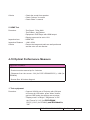
Check pattern
- Test signal: 1024 x 768 @60Hz ��������
(for P5271/P5290/P5271i);
1280 x800@75H (for P5390W)
- Test pattern: 64 gray RGBW
* After finishing ADC adjustment, check 64 gray RGBW pattern.
Inspection item
- Color saturation
Criteria
- There should not have any lack of RGBW. The color should appear normal and sort in right order.
- Color levels should be sufficient and normal. (the unidentified color levels on both left and right sides should not over 8 color levels.)
64 gray RGBW
P5271/P5290/P5390W/P5271i Confidential
4-
4-9 Video Performance
1. CVBS
Procedure - Test equipment: DVD player
- Test signal: CVBS
Inspection item - Video performance test
Inspection Distance - 1.8M ~2.5M
Criteria - Check any abnormal color, line distortion or any noise on the screen.
- Check the sound from speaker.
Motion video
2. S-Video
Procedure - Test equipment: DVD player
- Test signal: S-Video
Inspection item - Video performance test
Inspection Distance - 1.8M ~2.5M
Criteria - Check any abnormal color, line distortion or any noise on the screen.
- Check the sound from speaker.
3. HDTV/Component
Procedure - Test equipment: DVD player
- Test signal: Ycbcr/YPbPr
Inspection item - HDTV performance test
Inspection Distance - 1.8M ~2.5M
Criteria - Check any abnormal color, line distortion or any noise on the screen.
- Check the sound from speaker.
4. Audio Test
Procedure - Test equipment: DVD player
- Test signal: CVBS
Inspection item - Audio performance test
Inspection Distance - 1.8M ~2.5M
P5271/P5290/P5390W/P5271i Confidential
4-
Criteria - Check the sound from speaker.
- Check "Volume" is normal
- Check "Mute" is normal
5. HDMI Test
Procedure - Test Signal : 720p,1080i
- Test Pattern : Any Pattern
- Equipment: DVD Player with HDMI output
- Display type must be set to 16:9
Inspection item - HDMI Test
Inspection Distance - 1.8M ~2.5M
Criteria - Ensure the image and audio are well performed and the color can not discolor.
4-10 Optical Performance Measure
Inspection Condition
- Environment luminance: 2 Lux
- Product must be warmed up for 3 minutes
- Distances from the screen: 2 M (for P5271/P5290/P5271i); 1.8M (for
P5390W)
- Screen Size: 60 inches diagonal
1. Test equipment
Procedure - Connect VGA IN port of Projector with VGA port of Chroma by VGA cable, press "Menu" button, get into OSD mode, the settings are as below:
- "Display mode" is "Bright", "Brightness" is "50"
the "Format" is "4:3" (for P5271/P5290/
��������������������������������� P5271i);”16:9” (for P5390W)���������������������
, and "ECO Mode" is "Off".
P5271/P5290/P5390W/P5271i Confidential
4-
2. Brightness
Procedure - Full white pattern
- Use CL100 to measure brightness values of P1~P9.
- Follow the brightness formula to calculate
brightness values.
☼ Brightness Formula
Avg. (P1~P9)*1.1m Full white pattern
2
Criteria
● 1300 ANSI lumen (for P5271/P5271i)
● 1750 ANSI lumen (for P5290/P5390W)
3. Full On/Full Off Contrast
Procedure
- Full white pattern & full black pattern
- Use CL100 to measure brightness values of full
white pattern P5 & full black pattern B5
- Follow Contrast formula to calculate contrast values.
☼ Contrast Formula
P5/B5
Note: P
5 = Lux
������������������������������������
of center
�����������������������������
����������������������
in full���������������
white ��������
pattern�
Criteria
Full black pattern
B5 =Lux of center in full black pattern
● 2800: 1 (for P5271����������������������
/P5271i/ P5290/P5390W�)
4. Uniformity
Procedure
- Full white pattern
- Use CL100 to measure brightness values of P1~P9
(see image: full white).
- Follow the Uniformity formula to calculate
average values.
☼ Uniformity Formula
JBMA Uniformity = Avg. (P1, P3, P7, P9)/P5X100%
Criteria
● 65%
P5271/P5290/P5390W/P5271i Confidential
4-10
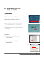
4-11 Network Function Test
(Only for P5271i)
1. Projector
�����������������
Setting
(1) Power on projector.
(2) Press “Menu” to get into OSD Mode.
(3) Select “Setting ->Wireless”, choose “On”
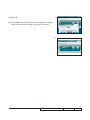
(4) Record projector IP address through projected image (Record IP address: 192.168.42.106).
(5) Connect projector with PC by LAN cable (please refer to 4-2).
2. PC Setting
2. (1)
(1). Double click the "Local area connection".
- Click "Properties".
(2). Select "Internet protocol (TCP/IP)".
- Click "Properties".
2. (2)
P5271/P5290/P5390W/P5271i Confidential
4-11
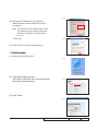
2. (3)
(3). Modify the IP address to 192.168.42.11 Modify Subnet mask to 255.255.255.0(as red square). Note: The HOST ID (192.168.42.XXX) of PC IP address must be different from the projector IP address recorded down in 4-11-1.
2. (4)
- Click "OK".
(4). Click "Close" to exit the setting screen.
3. Test
��������������
Procedure
(1). Execute "Internet Explorer".
3. (1)
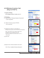
(2). Visit the IP address:http:// 192.168.42.106,then click "Download Acer eProjection Management".
3. (2)
(3) Click "Save".
3. (3)
P5271/P5290/P5390W/P5271i Confidential
4-12
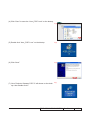
(4) Click “Save” to save the “Acer_P5271.exe” on the destop.
3.(4)
(5) Double click “Acer_P5271.exe” on the destop.
3.(5)
(6) Click “Next”.
3.(6)
3.(7)
(7) “Acer Projector Gateway P5271i” will shown on the desk- top. then double click it.
P5271/P5290/P5390W/P5271i Confidential
4-13
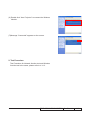
(8) Click “Ok”.
3.(8)
(9) The software window will show as right picture is enough, check if the projection image is same as PC screen.
3.(9)
P5271/P5290/P5390W/P5271i Confidential
4-14
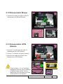
4-12 Wireless Function Test
(Only for P5271i)
1. Projector Setting
-The setting procedure is same as 4-11-1.
2. PC Setting
(1). Right click the "Wireless Network Connection".
- Click "Properties".
(2). Select "Internet protocol (TCP/IP)".
- Click "Properties".
(3). Modify the IP address to 192.168.42.12 Modify Subnet mask to 255.255.255.0(as red square). Note: The HOST ID (192.168.42.XXX) of PC IP address must be different from the projector IP address recorded down in 4-11-1.
- Click "OK".
(4) Click "OK".
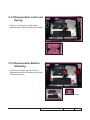
(5) Right click the "Wireless Network Connection".
- Click "View Available Wireless Networks".
P5271/P5290/P5390W/P5271i Confidential
4-15
(6) Double click “Acer Projector” to connect the Wireless Module.
(7)Message “Connected” appears on the screen.
2. Test Procedure
Test Procedure for Network function test and Wireless
function test is the same, please refer to 4-11-3.
P5271/P5290/P5390W/P5271i Confidential
4-16
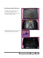
4-13 Others
1. Function Inspection
General
- All OSD functions must be checked for functionality.
When OSD menu is displayed, there shall be no
visible peaking, ringing, streaking, or smearing
artifacts on the screen.
Factory Default
- The factory settings (with appropriate centering,
size, geometry distortion, etc.) shall be displayed
upon “Recall” is selected from OSD.
Display Size
- All preset modes shall expand to full screen size
using OSD Horizontal and Vertical Size controls.
Display Data Channel - The purpose of the DDC test is to verify the
(DDC)
DDC1/DDC2B operation of the projector and to
verify Plug & Play function.
Acoustic
- High pitch sound from cooling fan and color wheel is
unacceptable.
2. Check points for exterior and print pattern
Check item
Text & Pattern
Exterior
Focus ring
Logo
Check point
Missing letters & pattern or blurry prints are
unacceptable.
Dirt, scrape, water ripples and uneven color are
unacceptable.
Focus ring is functioning smoothly.
Missing logo, missing prints and blurry prints are
unacceptable
Screw
All screws should be fixed and in right type.
Pedestal
Well-functioned
Lamp Cover
It should be locked in the correct place.
Plastic Parts
Safety or warning
label
All plastic parts can not be broken and damaged.
All safety and warning labels should be visible,
including all contents.
All interface connectors should be complete and
workable.
Connector
P5271/P5290/P5390W/P5271i Confidential
4-17
Chapter 5
Firmware Upgrade
Section 1: System Firmware Upgrade
(for all models)
5-1-1 Equipment Needed
Software: (DDP 2431- USB)
- DLP Composer Lite 9.2
- Firmware (*.img)
- Library file (P5271 P5290 FlashDeviceParameters) (library file has to put in PC and set right path in 5-5 step 3)
Note: - Please download "DLP Composer Lite 9.2" and "P5271 P5290 FlashDeviceParameters" from website to upgrade FW procedure.
Hardware:
- Projector
- Power Cord: 42.50115G001
- USB Cable: 42.87304G001
- PC or Laptop
Note: - The FW upgrade procedure for P5290/P5390W/P5271i is the same as P5271, we take P5271 as an example here.
P5271/P5290/P5390W/P5271i Confidential
5-
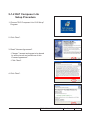
5-1-2 DLP Composer Lite
Setup Procedure
1. Choose "DLP Composer Lite V9.2 Setup"
Program.
2. Click "Next".
3. Read "License Agreement".
-C
hoose "I accept and agree to be bound
by all the terms and conditions of this
License Agreement".
- Click "Next".
4. Click "Next".
P5271/P5290/P5390W/P5271i Confidential
5-
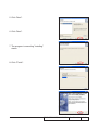
5. Click "Next".
6. Click "Next".
7. The program is executing "installing" status.
8. Click "Finish".
P5271/P5290/P5390W/P5271i Confidential
5-
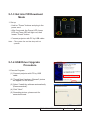
5-1-3 Get into FW Download Mode
1. Set up
- Hold on "Power" buttons and plug in the power cord.
- After 5 seconds, the Power LED, Lamp LED and Temp LED will light red, then loosen "Power" button.
-C
onnect projector with PC by USB cable.
Note: - The system fan and the lamp will not
operate.
5-1-4 USB Driver Upgrade Procedure
(2)
1. Execute Program
(1) Connect projector with PC by USB cable.
(2) "Found New Hardware Wiszard" picture will appear on the screen.
(3)
(4)
(3) Select "Install the software automatically (Recommended)".
(4) Click "Next".
(5) Searching picture, please wait for several seconds.
P5271/P5290/P5390W/P5271i Confidential
5-
(6) Click "Finish", then the USB driver has been installed successfully.
Note: - If you have installed the USB driver, there is no need to perform this action.
(6)
5-1-5 Firmware Upgrade Procedure
1. Execute the "DLP ComposerTM Lite 9.2" file.
2. Click "Edit" and "Perferences".
P5271/P5290/P5390W/P5271i Confidential
5-
3. Click "Library".
-C
lick the "Browse" and navigate to the
directory where you put the Library files in.
- Click "P5271 P5290 FlashDeviceParameters" folder.
- Click "OK".
4. Click "Communications".
- Select "USB".
- Click "OK".
5. Choose "Flash Loader".
-C
lick "Browse" to search the firmware file
(*.img).
- Click "Open".
6. Select "Skip Boot Loader Area".
(select "32KB").
- Click "Reset Bus" to erase the flash memory.
P5271/P5290/P5390W/P5271i Confidential
5-
7. If the FW is ready, click "Start Download" to
execute the firmware upgrade.
- Click "Yes".
8. Proceeding Picture.
9. It takes about several minutes, the firmware upgrade process is finished, "Download completed" will appear on the screen.
- The projector will automatically turn on.
-U
nplug USB cable.
10. Check FW version. - Get into the service mode to check the firmware version.
( To get into service mode, please press
"Power", "Left", "Left" and "Menu" buttons
sequentially.)
P5271/P5290/P5390W/P5271i Confidential
5-
5-1-6 Waveform Download (for P5271/P5271i)
- Plug in power cord.
- Hold on the "Up" button, then press the "Power" button, the Power LED lights blue.
- Wait a moment, the Temp LED flashes red.
- After several seconds, the Lamp LED and Temp LED light red.
- Loosen the "Up" button.
- After that, the projector will automatically get into standby status.
- Waveform Download is completed.
Note: - This step must be executed after Lamp Driver changed.
5-1-7 Restore Blower Speed
- Plug in power cord.
- Hold on the "Left" button, then press the "Power" button.
- After about 2 seconds, the Power LED lights purple , the Lamp LED and Temp LED light red.
- The projector will be on and the message appears as the right picture shows.
- After about 70 seconds, the Lamp LED and Temp LED will be off, the Power LED will light blue.
P5271/P5290/P5390W/P5271i Confidential
5-
- Get into the service mode.
- Select "Thermal Settings" to check that the Blower Speed has been restored.
( To get into service mode, please press
"Power", "Left", "Left" and "Menu" buttons
sequentially.)
- The procedure is completed.
Note: - This step must be executed after changing FW, Main Board or Lamp Blower.
P5271/P5290/P5390W/P5271i Confidential
5-
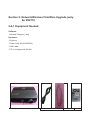
Section 2: Network/Wireless FirmWare Upgrade (only for P5271i)
5-2-1 Equipment Needed
Software :
- Network Program (*.bin)
Hardware :
- Projector
- Power Cord (42.00106G001)
- LAN Cable
- PC or a Laptop with WLAN
P5271/P5290/P5390W/P5271i Confidential
5-10
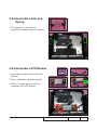
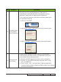
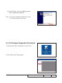
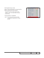
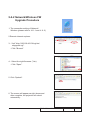
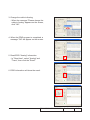
5-2-2 Network/Wireless FW Upgrade Procedure 1. The connection setting of Network /
Wireless (please refer to 4-11-1 and 4-11-2).
2.Execute internet explorer.
3. - Visit "http://192.168.42.106/cgi-bin/
rdupgrade.cgi".
- Click "Browse"
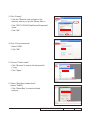
4. - Select the right firmware (*.bin).
- Click "Open".
5. Click "Update".
6. The screen will appear as right shows,and after complete, the projector will reboot automaticlly.
P5271/P5290/P5390W/P5271i Confidential
5-11
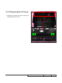
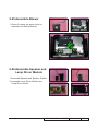
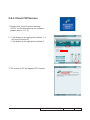
5-2-3 Check FW Version
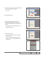
1. Double click “Acer Projector Gateway
P5271i” on the destop(setup the software, please refer to 4-11-3).
2. - Click button as the right picture shows 1, it will show Projector IP.
- Click button as the right picture shows 2.
1
2
3. The screen of PC will appear FW's Version.
P5271/P5290/P5390W/P5271i Confidential
5-12
Chapter 6
EDID Upgrade
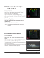
6-1 EDID Introduction
Extended Display Identification Data is a VESA standard data format that contains basic
information about a display device and its capabilities, including vendor information,
maximum image size, color characteristics, factory pre-set timings, frequency range limits,
and character strings for the monitor name and serial number.
The information is stored in the display and is used to communicate with the system
through a Display Data Channel (DDC), which sites between the display device and the
PC graphics adapter. The system uses this information for configuration purposes, so the
monitor and system can work together.
Note: - If a display device has digital input ports, like DVI or HDMI, but without EDID in its Main Board, the display device will show no image while the input source is digital signal.
- The EDID Upgrade procedure for P5290/P5390W/P5271i is the same as P5271, we take P5271 as an example here.
- After EDID upgrading, please execute "Default Language Reset".
P5290/P5271/P5390W/P5271i Confidential
6-
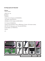
6-2 Equipment Needed
Software
- EDID Program
- EDID File (*.ini)
Hardware
- Projector
- Power Cord for Projector (42.53506G002)
- VGA Cable (42.87305G102)
- HDMI(M) to DVI(F) Adapter (42.82B13G001)
- DVI Cable (42.83N06G001)
- Generic Fixture (80.00001.001) for EDID Key-in (Fixture: JP3 must be closed)
- RS-232 9 Pin Cable (pin to pin, F-M) (42.83C07G001)
- Power Adapter (47.57803G001)
- Monitor
- PC
P5290/P5271/P5390W/P5271i Confidential
6-
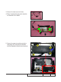
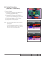
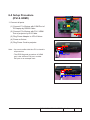
6-3 Setup Procedure
(VGA IN 1 & VGA IN 2)
RS232 Cable
Adapter
P1
1. Connect all ports
(1) Connect P1 of fixture with COM Port of PC/Laptop by RS232 Cable.
JP2
JP3
P2
(2) Connect P2 of fixture with VGA IN 1 / VGA IN 2 Port of projector by VGA Cable.
VGA Cable
(3) Plug Power Adapter to JP2 of fixture.
(4) Plug Power Cord to projector.
Note: - You must confirm that the JP3 is closed in all procedure.
- The EDID Upgrade procedure of VGA IN 2 port is the same as VGA IN 1 port, we take VGA IN 1 port as an example here.
VGA IN 1 Port
Power Port
VGA IN 2 Port
Power Port
P5290/P5271/P5390W/P5271i Confidential
6-
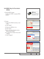
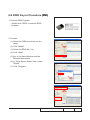
6-4 EDID Key-In Procedure (VGA)
1. Execute EDID Program
- Double click "EDID" to execute EDID program.
2. Process
(2)
(1) Select the COM Port which you are using.
(2) Click "Model".
(1)
(3) Select the EDID file (*.ini).
(4) Click "Open".
(5) Key in the Serial Number into the Barcode blank space.
(6) In "Write Source Select" item, select
"Analog".
(7) Click "Program".
(3)
(4)
(5)
(7)
(6)
P5290/P5271/P5390W/P5271i Confidential
6-
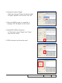
3. Change the cable to Analog
- When the message "Please change the cable to Analog" appears on the screen, click "OK".
4. When the EDID program is completed, a message "OK" will appear on the screen.
5. Read EDID "Analog" information
- In "Read item", select "Analog" and "Trans", then click the "Read".
6. EDID information will show the result.
P5290/P5271/P5390W/P5271i Confidential
6-
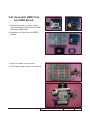
6-5 Setup Procedure
(DVI & HDMI)�
RS232 Cable
Adapter
P1
1. Connect all ports
(1) Connect P1 of fixture with COM Port of PC/Laptop by RS232 Cable.
JP2
JP3
P3
(2) Connect P3 of fixture with DVI / HDMI Port of projector by DVI Cable.
DVI Cable
(3) Plug Power Adapter to JP2 of fixture.
(4) Power on fixture.
(5) Plug Power Cord to projector.
DVI Port
Note: - You must confirm that the JP3 is closed in all procedure.
- The EDID Upgrade procedure of HDMI port is the same as DVI port, we take DVI port as an example here.
Power Port
HDMI Port
HDMI (M) to DVI (F) Adapter
P5290/P5271/P5390W/P5271i Confidential
6-
6-6 EDID Key-In Procedure �����
(DVI)
1. Execute EDID Program
- Double click "EDID" to execute EDID program.
2. Process
(1) Select the COM port which you are using.
(2)
(2) Click "Model".
(3) Select the EDID file (*.ini).
(4) Click "Open".
(1)
(5) Key in the Serial Number into the Barcode blank space.
(6) In "Write Source Select" item, select "Digital".
(7) Click "Program".
(3)
(4)
(5)
(7)
(6)
P5290/P5271/P5390W/P5271i Confidential
6-
3. Change the cable to Digital
- When the message "Please change the cable to Digital" appears on the screen, click "OK".
4. When the EDID program is completed, a message "OK" will appear on the screen.
5. Read EDID "HDMI" information
- In "Read item", select "Digital" and "Trans", then click the "Read".
6. EDID information will show the result.
P5290/P5271/P5390W/P5271i Confidential
6-
6-7 Un-lock SNID and Default Language Reset
- Plug in power cord.
- Hold on the "down" button, then press the "Power" button.
Note: - After about 2 seconds, the Power LED lights blue, the Lamp LED and Temp LED light red, then loosen the "Down" button.
- After that, please check the LED status and judge the actions as the following table:
Power LED Status
Power (blue) + Temp (red) + Lamp (red)
Power (blue) + Temp (red)
Result
OK
Fail
Note: If it is fail, please do the actions as above steps.
S/N General rule:
Use the last 1 digit code (as red word) for language information
Language Code (F)
1
2
3
4
5
6
7
8
Default Language
English
Thailand
Japan
TC
SC
Russian
Germany
Hungarian
P5290/P5271/P5390W/P5271i Confidential
6-
Appendix A (Exploded Image)
Note: This chapter is only designed to show the exploded image of the projector. For updated part numbers, please refer to RSPL report.
D.C.
3
5
4
1
2
Item
P/N
Description
1
2
3
4
4
70.8EP03G001
70.8BV02G001
70.8BV03G001
SP.8BV01GC01
SP.8EP01GC01
70.8BV40GR01
70.8EP10GR01
51.8BV15H001
ASSY BOTTOM HOUSING MODULE P5290
FRONT COVER MODULE P5271
TOP COVER MODULE P5271
LAMP MODULE FOR PROJECTOR P5271/P5271i
LAMP MODULE FOR PROJECTOR P5290/P5390W
ASSY BACK COVER MODULE P5271(SERVICE)
ASSY BACK COVER MODULE P5290(SERVICE)
BACK COVER P5271
5
Parts Supply
P5271/P5290/P5390W/P5271i Confidential
V
V
V
V
ASSY FRONT COVER MODULE
7
6
3
1
4
2
5
Item
P/N
Description
Parts Supply
4
42.85E04G001
5
6
7
61.8BV11H001
51.8BV11G002
51.8BV24H001
ASSY FRONT COVER MODULE P5271(SERVICE)
ASSY FRONT COVER P5271i
FRONT IR LENS P5271
PCBA IR BD FOR P5271
W.A. 3P #28 L230mm WITH L165mm GASKET IR
RECEIVER DV11
ACER LOGO FRONT P5271
FRONT IR MYLAR P5271i
FRONT LIGHT CUT P5271
V
1
2
3
70.8BV44GR01
75.8BV08G002
51.8BV12H001
80.8BV05G001
P5271/P5290/P5390W/P5271i Confidential
II
ASSY TOP COVER MODULE
6
5
4
2
1
3
Item
P/N
70.8BV45GR01
1
2
3
4
5
6
51.8BV10H002
61.8BV17H001
70.8BV19G001
85.YA121G030
75.8BV05G002
51.8BV21H001
Description
Parts Supply
ASSY TOP&LAMP COVER MODULE
P5271(SERVICE)
TOP COVER P5271i
LAMP COVER SPRING P5271
KEYPAD MODULE P+R P5271
SCREW FLAT HEAD TAP M1.7*3 Ni
ASSY LAMP COVER MODULE P5271i
ACER LOGO TOP PLASTIC P5271
P5271/P5290/P5390W/P5271i Confidential
V
III
ASSY KEYPAD MODULE
Item
P/N
1
2
3
4
80.8BV03G002
51.8BV17H002
42.00303G001
51.8BV04G001
5
85.YA123G040
6
41.85H06G001
Description
Parts Supply
PCBA KEYPAD BD. FOR P5271
KEYPAD MODULE P+R P5271i
FFC KEYPAD TO M/B 24P P=0.5 120mm EP752
KEYPAD ISOLATED MYLAR P5271
SCREW(TAPPING FLAT HEAD NI M3*4)AD2022m
EMI GASKET W10*H8*L15
P5271/P5290/P5390W/P5271i Confidential
V
V
IV
ASSY BOTTOM COVER MODULE
2
9
13
5
8
12
7
11
10
6
3
5
1
4
P5271/P5290/P5390W/P5271i Confidential
Item
P/N
70.8BV41GR01
1
2
3
4
5
6
7
8
9
10
11
12
13
52.8BV04H001
86.03123G035
51.8BV07H001
52.8BV02H002
85.1A126G040
51.86809G001
61.86814G001
61.8BA18G001
51.8BV13H002
51.8BV14H002
61.8BV16H001
70.8BV21G001
75.8BV06G002
Description
Parts Supply
ASSY BOTTOM COVER MODULE
P5271(SERVICE)
ADJUST FOOT RUBBER P5271
HEX CAP HEAD NUT M3*0.5P L3.5
ELEVATOR PLASTIC FOOT P5271
ELEVATOR RUBBER FOOT P5271i
SCREW PAN MECH M2.6*4 Ni
ELEVATOR BODY NYLON+GF PD120
ELEVATOR EXTEND SPRING PD120
ELEVATOR BRACKET P1266
LATCH LEFT P5271i
LATCH RIGHT P5271i
LATCH SPRING P5271
ELEVATOR MODULE P5271
ASSY BOTTOM COVER P527I
P5271/P5290/P5390W/P5271i Confidential
V
VI
ASSY LVPS MODULE
4
1
4
2
3
Item
P/N
1
75.8BV01GP01
1
75.8BV02GP01
2
42.00451G001
3
42.83M06G001
4
85.1F123G060
Description
Parts Supply
ASSY MATRITEK 230W LVPS FOR P5271.
STAND-BY<1W (P5271)
ASSY MATRITEK 280W LVPS .STAND-BY<1W
(P5290/P5390W)
W.A. 16P 240mm LVPS TO MAIN BD UL1007
EP752
CABLE W.A. 2P #20 180mm LAMP DRIVER TO
LVPS 2400MP
SCREW PAN MECH W/SF M3*6 Ni GREEN
P5271/P5290/P5390W/P5271i Confidential
V
V
V
V
VII
ASSY LAMP DRIVER MODULE
5
3
6
4
6
2
1
Item
P/N
1
75.8BW01G002
1
75.8EP01G001
2
51.8BV04H001
3
42.00425G001
4
5
6
42.0043MG001
51.8BV01G001
85.1A123G040
Description
Parts Supply
ASSY OSRAM LAMP DRIVER O3 MID
230W(Gen5_Panyu+E20.8) (P5271)
ASSY OSRAM O3 PRO Lamp Driver (CODE:
A61494F00DG) (P5290/P5390W)
LAMP DRIVER HOLDER P5271
W.A. 5P #28 100mm MAIN BOARD/LAMP DRIVER
1409X
LAMP CONNECTOR SOCKET P5271
LAMP DRIVER ISOLATED MYLAR P5271
SCREW PAN MECH M3*4 Ni
P5271/P5290/P5390W/P5271i Confidential
V
V
V
VIII
ASSY MAIN BOARD MODULE
5
3
1
11
4
6
9
13
10
8
2
7
3
12
Item
P/N
Description
Parts Supply
70.8BV39GR01
70.8EP09GR01
ASSY MAIN BOARD MODULE P5271(SERVICE)
ASSY MAIN BOARD MODULE P5290(SERVICE)
V
V
1
80.8EP01G001
PCBA MAIN BD FOR P5290
2
3
61.8BV06H002
61.8BV07H001
4
61.8BV15H001
5
6
7
8
9
10
11
12
13
51.81541G001
41.83R07G001
41.83J02G001
41.81H03G001
41.83J07G001
41.82G03G001
51.81542G001
51.81542G001
41.89K06G001
MAIN BOARD SHIELDING BOTTOM P5271i
MAIN BOARD SHIELDING TOP P5271
MAIN BOARD SHIELDING BOTTOM BRACKET
P5271
TAPE 3M J350 17*30mm
EMI GASKET W7*H7*L50mm
EMI GASKET W5*H1.0*L245mm PD527
EMI GASKET FOR DVI CONNECTOR
EMI TAPE W5*H1.0*L11mm PD527
EMI GASKET USB CONNECTOR EP719
TAPE 3M J350 17*15mm
TAPE 3M J350 17*15mm
EMI TAPE W50*L120
P5271/P5290/P5390W/P5271i Confidential
IX
ASSY FAN MODULE
5
2
1
3
4
6
Item
P/N
1
2
3
4
5
6
49.83C04G001
52.8BV06H001
52.L1309G002
61.89547G001
61.8BV05H001
41.8AV01G001
Description
Parts Supply
SUNON 9225 AXIAL FAN/KDE1209PTBX
FAN 9225 RUBBER BOTTOM P5271
FAN 9225 RUBBER TOP FOR PD726
92*25 FAN SCREW M2.6 4100MP
FAN 9225 BRACKET P5271
EMI GASKET W6*H3*L50
P5271/P5290/P5390W/P5271i Confidential
V
ASSY BLOWER FAN MODULE
2
3
1
Item
P/N
Description
Parts Supply
1
52.87306G001
2
49.8BY01G001
V
3
85.WD123G080
RUBBER BLOWER FAN FRAME 2100MP
SUNON 50*50*20mm BLOWER GB1205PKV4-AY
S76.F.X.GN
SCREW PAN TAP 3*8 W/WASHER Ni
P5271/P5290/P5390W/P5271i Confidential
XI
ASSY ENGINE MODULE
13
12
14
15
3
10
2
5
8
4
11
9
1
15
7
6
P5271/P5290/P5390W/P5271i Confidential
XII
Item
P/N
1
2
3
4
5
6
51.8BV02H001
51.8BV01H001
85.WA122G040
51.8AF12G001
61.8AF30G001
70.8BV24G001
70.8BV42GR01
70.8BY13G001
70.8BY17G001
70.8BV27G001
70.8BV28G001
70.8BV29G001
70.8EP02G001
70.8BV32G001
85.1A626G050
85.1A326G060
7
8
9
10
11
12
13
14
15
Description
Parts Supply
FOCUS RING P5271
ZOOM RING P5271
SCREW PAN TAP M2*4 NI
PLASTIC WASHER NWT-38 PINGOOD
SHOULDER SCREW M3.0*7 VP22
ASSY ENGINE BRIDGE MODULE P5271
ASSY ENGINE MODULE P5271(SERVICE)
ASSY ENGINE BOTTOM MODULE EX765
ASSY LENS SHIFT MODULE EX765
ASSY LENS SHIFT GEAR H P5271
ASSY LENS SHIFT GEAR V P5271
ASSY ENGINE TOP MODULE P5271 Z20
COLOR WHEEL MODULE P5290
ASSY LAMP SUPPORT HOLDER 230W P5271
SCREW PAN MECH M2.6*5 BLACK NYLOK
SCREW PAN HEAD MECH M2.6*6 BLACK
P5271/P5290/P5390W/P5271i Confidential
V
XIII
ASSY ENGINE TOP MODULE
11
9
3
1
7
2
6
10
4
5
8
12
Item
P/N
Description
Parts Supply
1
41.8BV01G001
EMI GASKET W6*H13*L40
2
48.8CQ01G003
0.55” XGA 2xLVDS SERIES 450 DMD -8 TI 1076-603cB
V
2
48.8EJ01G001
0.65’’ WXGA 2xLVDS SERIES 450 DMD -8 TI 1280603cB
V
3
52.8BY01G001
ENGINE OFF LIGHT HEATSINK SILCONE RUBBER
X20/A20
4
52.8CP02G001
DMD BOARD RUBBER X1161
5
52.8CP04G001
S450 0.55” XGA/SVGA DMD thermal pad, FUJIPOLY,
Sarcon XR-HE, 18.4x12.5x0.5 mm
6
52.8CP01G001
DMD RUBBER X1161
7
61.8BY01G021
ENGINE TOP COVER Mg Z20
8
61.8BV27H001
ENGINE HEATSINK Z20 P5271
9
61.8BY03G001
ENGINE OFF LIGHT HEATSINK AL X20/A20
10
80.8BV02G002
PCBA DMD BOARD FOR P5271(S450)
11
85.1A326G060
SCREW PAN HEAD MECH M2.6*6 BLACK
12
85.4A826G118
STEP SCREW FOR TYPEX DMD M2.6*11.8mm,X15
P5271/P5290/P5390W/P5271i Confidential
V
V
XIV
ASSY ENGINE BOTTOM MODULE
5
9
6
8
7
10
2
1
3
4
Item
P/N
Description
1
23.8BV02G001
ONE SURFACE COATING 37.2 x 23.2 mm FOR X20
2
23.8BV06G001
ASPHERICAL GLASS RELAY X20 L1. ψ36.5 mm
3
51.8BY01G001
ENGINE BOTTOM BMC X20/A20
4
52.85808G001
PORON-LENS BLACK XB31
5
52.8BY03G001
ENGINE BOTTOM MIRROR SPONGE HT800 X20/A20
6
61.8BY08G001
ENGINE MIRROR SPRING SUS301 X20/A20
7
61.8BY10G001
ENGINE RELAY FIXED PLATE SUS301 X20/A20
8
85.1A626G050
SCREW PAN MECH M2.6*5 BLACK NYLOK
9
51.8BY31G001
MIRROR MYLAR EX765
10
51.8BY37G001
ENGINE RELAY MYLAR X20/A20
Parts Supply
P5271/P5290/P5390W/P5271i Confidential
XV
ASSY COLOR WHEEL MODULE
1
2
7
3
5
4
6
Item
P/N
Description
1
23.8CQ19G002
YO 6S HE3 CW R81Y41G84C31W52B71, URD20 MOTOR
70.8BV43GR01
ASSY COLOR WHEEL MODULE P5271(SERVICE)
2
52.83615G001
COLOR WHEEL DISC RUBBER, EzPro755
3
61.83628G002
COLOR WHEEL SHOULDER SCREW NICKEL M2*4.8
FILLIST
4
61.8BY09G001
ENGINE COLOR WHEEL HOLDER SECC X20/A20
5
80.8AA04G001
PCBA PHOTO SENSOR BOARD FOR 1409X
6
51.8BY35G001
COLOR WHEEL PHOTOSENSOR MYLAR FOR EX765
7
85.1A626G040
SCREW PAN MECH M2.6*4 BLACK NYLOK
Parts Supply
P5271/P5290/P5390W/P5271i Confidential
V
XVI
A.K.
7
5
10
9
19
18
17
12
16
15
13
20
8
11
14
1
4
3
2
6
14
P5271/P5290/P5390W/P5271i Confidential
XVII
Item
P/N
Description
Parts Supply
1
51.00201G001
HANDLE BAR 1.PE HD70
2
51.00200G001
HANDLE BAR 2. PE HD70
3
55.8BV02H001
CARTON CARRY BOX P5271
4
35.82V02G001
LABEL CARTON(SEAL) 110*50mm PD120
5
51.8BV15G001
TOP COVER MYLAR P5271
6
35.52302G091
LABEL CARTON 108*92 BLANK
V
7
35.86301G001
SPEC LABEL BLANK PD120
V
8
53.8BV01G001
SOFT CARRY BAG P5271
9
70.8BV25G001
ASSY AK PACKAGE MODULE 1 P5271
10
51.52109G003
PE BAG 450*350*0.07 FOR OPTOMA
11
56.8BV02H001
AIR BAG TOP P5271
12
56.8BV02H001
AIR BAG TOP P5271
13
56.8BV03H001
AIR BAG RIGHT P5271
14
35.00029G001
ACER TAPE 45M FOR CARTON
15
42.00120G011
CABLE POWER CORD 1.8M SP-023/IS-14 EUROPE
DIS-WARNING LABEL
16
42.00110G011
CABLE POWER CORD 1.8M SP-60/IS-14 UK DISWARNING LABEL
V
17
42.00131G011
CABLE POWER CORD 1.8M SP-027/IS-14 SWITZERLAND DIS-WARNING LABEL
V
18
57.00001G001
PACK SIO2 DRIER 20g
19
70.8BV26G001
ASSY AK PACKAGE MODULE 2 P5271
20
45.8BV01G001
INFRARED REMOTE CONTROLLER L9 WITH LASER
Silver-grey For
P5271/P5290/P5390W/P5271i Confidential
V
XVIII
Appendix B
I. Serial Number System Definition
Serial Number Format for Projector (take P5271 for example)
EYJ8701001
1 929
00000
2 3 59
4
0
5
1
6
1
:
EYJ8701001 = Part Number
2
:
929 = Date Code (ex:2009 = 9, the twenty-ninth week of the year = 29)
3
:
00000 = Serial Numbers
4
:
59 = Manufacturing Code
5
:
0 = Version Code
6
:
1 = Auto-Language Code
EX: EYJ8701001929000005901
This label represents the serial number for P5271. It is produced at CPC on twenty-ninth
week of 2009. Its serial code is 00000.
P5271/P5290/P5390W/P5271i Confidential
I
II. PCBA Code Definition
PCBA Code for Projector
A B
1
XXX
2
XXXXXXXXX CC
3
4
5
XXX EEEE
6
7
1
:
ID
2
:
Vendor Code
3
:
Firmware Version
4
:
P/N
5
:
MB version
6
:
Date Code
7
:
S/N
P5271/P5290/P5390W/P5271i Confidential
II
Appendix C
RS232 function command summary table
General command type (Projector "receives�����������
"����������
commands)
No
1
2
3
4
5
6
7
8
9
10
11
12
13
14
15
16
17
18
19
20
21
22
23
24
25
26
27
28
29
30
31
Code (character)
OKOKOKOKOK\r
* 0 IR 001\r
* 0 IR 002\r
* 0 IR 004\r
* 0 IR 006\r
* 0 IR 007\r
* 0 IR 008\r
* 0 IR 009\r
* 0 IR 010\r
* 0 IR 011\r
* 0 IR 012\r
* 0 IR 014\r
* 0 IR 015\r
* 0 IR 016\r
* 0 IR 017\r
* 0 IR 018\r
* 0 IR 019\r
* 0 IR 020\r
* 0 IR 021\r
* 0 IR 022\r
* 0 IR 023\r
* 0 IR 024\r
* 0 IR 025\r
* 0 IR 026\r
* 0 IR 027\r
* 0 IR 030\r
* 0 IR 031\r
* 0 IR 032\r
* 0 IR 033\r
* 0 IR 034\r
* 0 IR 035\r
Function feature
Power On
Power On
Power Off
Keystone
Mute
Freeze
Menu
Up
Down
Right
Left
Re-Sync
Source Analog RGB for D-sub
Source Digital RGB
Source PbPr for D-sub
Source S-Video
Source Composite Video
Source Component Video
Aspect ratio 16:9
Aspect ratio 4:3
Volume +
Volume –
Brightness
Contrast
Color Temperature
Hide
Source
Video: Color saturation adjustment
Video: Hue adjustment
Video: Sharpness adjustment
Query Model name
P5271/P5290/P5390W/P5271i Confidential
I
No
32
33
34
35
36
37
38
39
40
Code (character)
* 0 IR 036\r
* 0 IR 037\r
* 0 IR 042\r
* 0 IR 043\r
* 0 IR 046\r
* 0 IR 047\r
* 0 IR 048\r
* 0 IR 049\r
* 0 IR 050\r
Function feature
Query Native display resolution
Query company name
Keystone Up
Keystone Down
Zoom
e-Key
Color RGB
Language
Source HDMI
Note: The command with end "\r" means "Enter".
P5271/P5290/P5390W/P5271i Confidential
II