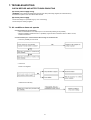
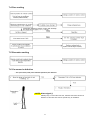
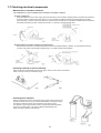
1
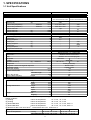
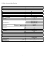
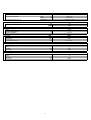
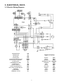
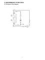
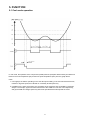
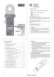
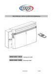
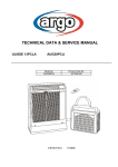
TECHNICAL DATA & SERVICE MANUAL
MAGICO 9.2
AMG26MIR
0.8180.469.0
07/2005
Page
3
3
4
1. SPECIFICATIONS
1-1 Unit Specifications
1-2 Major Component Specifications
6
6
2. DIMENSIONAL DATA
2-1 Unit Dimensions
7
7
3. ELECTRICAL DATA
3-1 Electric Wiring Diagram
8
8
4. REFRIGERANT FLOW DATA
4-1 Refrigerant Flow Diagram
5. FUNCTION
5-1 Cool mode operation
5-2 Dry mode operation (dehumidification)
5-3 Fan mode operation
5-4 Protection operations in cool and dry modes
5-5 Sleep function
5-6 Daily timer function
5-7 I-Feel function
5-8 Manual unit control and led indicators
5-9 Recovery from power failure
9
9
9
10
11
12
12
12
13
13
14
14
6. PERFORMANCE DATA
6-1 Performance Chart
7. TROUBLESHOOTING
7-1 Air conditioner does not operate
7-2 Some parts of air conditioners does not operate
7-3 Air conditioner operate, but abnormalities are observed
7-4 Poor cooling
7-5 Excessive cooling
7-6 If a sensor is defective
7-7 Checking electrical components
2
15
15
16
16
17
17
17
18
1. SPECIFICATIONS
1-1 Unit Specifications
Power source
220 - 240 V ~ 50 Hz
Voltage rating
230 V
Performance
Capacity (1)
Efficiency (2)
Air flow rate (evaporator)
Air flow rate (condenser)
Moisture removal
Moisture removal
Moisture removal
Electrical ratings
Available voltage range
Power input
Running amperes
Power input
Running amperes
Power input
Running amperes
Compressor locked rotor
(1)
(2)
W
W/W
m³/h
m³/h
l/h
l/24h
l/24h
Hi/Me/Lo
Hi/Me/Lo
(3)
(4)
Package dimensions
Weight
DEHUMIDIFICATION
WITHOUT AIR EXHAUSTING TUBE
2570
2,62
310 / 285 / 260
290 / 265 / 240
1,25
-
-
(3)
(3)
(4)
(4)
dB(A)
g
liters
mm
m
mm
m
260
240
27
51
198 - 264
V
W
A
W
A
W
A
A
Features
Controls/Temperature controls
Control unit
Timer
Fan speed
Air Filter
Operation sound Lp
(5) Hi/Me/Lo
Compressor
Refrigerant / Amount charged at shipment
Refrigerant control
Water tank capacity
Flexible exhaust tube
I.D.
extended length
Hole in the window
Electric cable with plug
length
Dimensions & Weight
Unit dimensions
COOLING
WITH AIR EXHAUSTING TUBE
925
4,1
-
970
4,4
1090
5
18
Microprocessor / I.C. Thermostat
Wireless remote control unit
ON/OFF 24 hours and program
3 and auto
1
Washable
55 / 53 / 51
51
Rotary (hermetic)
R410A / 590
Capillary tube
~ 3,3
115
1
138
2,9
Height
mm
Width
mm
Depth
mm
Height
mm
Width
mm
Depth
mm
Volume
m³
Net
kg
Shipping
kg
Data subject to change without notice
965
530
415
1180
595
500
0,35
34
36
Rating conditions
(1) Cooling
indoor air temperature:
27 °C d.b. , 19 °C w.b
(2) Cooling
indoor air temperature:
35 °C d.b. , 24 °C w.b
(3) Dehumidification
indoor air temperature:
27 °C d.b. , 21 °C w.b , 60% u.r.
(4) Dehumidification
indoor air temperature:
30 °C d.b. , 27 °C w.b , 80% u.r.
(5) Reference data: room size 100 m3 , reverberation time 0,5 s , distance 2 m
Operating limits
Indoor air temperature
maximum
Cooling
35 °C d.b. , 24 °C w.b
Dehumidification 35 °C d.b. , 28 °C w.b
3
minimum
16 °C d.b. , 14 °C w.b
16 °C d.b. , 14 °C w.b
1-2 Major Component Specifications
Controller PCB
Controls
Control circuit fuse
(CE)
Thermistor (coil sensor)
Resistance
(TH1)
25 °C
NTC
10 °C ± 5%
Thermistor (room sensor)
Resistance
(TH2)
25 °C
NTC
10 °C ± 5%
Fan & Fan Motor
Type
Q'ty ……. Dia. and lenght
No. Of poles
Rpm
Power input (230 V)
(FM)
M01974
Centrifugal blower
1…. Ø 170 / L 156
4
1275/1156/1058 with flexible exhaust tube retracted
109/84/80
GRY-WHT: 87,3 ÷ 101
WHT-VLT: 36,2 ÷ 41,6
VLT-YEL: 22,8 ÷ 26,3
YEL-PNK: 22,8 ÷ 26,3
GRY-BRN: 51,9 ÷ 59,6
Thermostat
150 ± 10
Automatic
mm
Hi/Me/Lo speed
W (Hi / Lo)
Coil resistance (25°C )
Ω
type
Safety devices
operating temp.
open
close
°C
°C
(C1)
µF
VAC
Run capacitor
Float microswitch
Contact rating
Compressor
Model
Nominal input (230 V)
Compressor oil
Coil resistance ( 20°C)
(MS)
WSA
Microprocessor
250 VAC - 3,15 A
3
450
up
down
CROUZET F83161.3
16(4) A - 250 VAC
open
close
(CM)
Rotary (hermetic)
W
type …. cc
C-R
Ω
C-S
Ω
5PS102EAA (R410A)
830
RB68A or Freol Alpha 68M ….. 350
3,86 ± 7%
3,30 ± 7%
Data subject to change without notice
4
Safety devices
Type
Operating temperature
Operating amperes (25 °C)
(OLR)
open
close
open with
Run capacitor (compressor)
°C
°C
(C3)
µF
VAC
Condensate pump
Model
Nominal input (230 V)
Winding resistance
(PC)
Pump relay
Contact rating
Coil supply
Coil resistance (20 °C)
(RP)
W
Ω
Heat exchanger coil
Coils
Rows
Fin pitch
Face area
Heat exchanger coil
Coils
Rows
Fin pitch
Face area
30
450
291036
5
778 ± 8%
VAC
kΩ
H62S
5 A - 220 V
230
17,2 ± 10%
mm
m²
EVAPORATOR COIL
Aluminium fin - 3/8" Copper tube
4
1,8
0,042
mm
m²
5
EXTERNAL TYPE
MRA99901-9201 or MRA99437
148 ± 5 °C
69 ± 9 °C
16 A in 6 ÷ 16 s
CONDENSER COIL
Aluminium fin - 7mm Copper tube
5
1,3
0,084
Data subject to change without notice
2. DIMENSIONAL DATA
2-1 Unit Dimensions
6
3. ELECTRICAL DATA
3-1 Electric Wiring Diagram
4,9
COMPRESSOR
CAPACITOR
RECEIVER
FAN MOTOR
OVERLOAD PROTECTOR
ELECTRONIC CONTROL
ALARM LIGHT
CONDENSATE PUMP
PUMP RELAY
ON/OFF SWITCH
FLOAT MICROSWITCH
ELECTRIC HEATER RELAY
SENSOR
RESISTANCE
TERMINAL PLATE
CM
Cx
IND
FM
OLRx
PCB
AL
PC
RP
SW
MS
RR
THx
Rx
TP
32
Legend of colors
BLACK
BLUE
BROWN
GREEN/YELLOW
ORANGE
RED
WHITE
YELLOW
GREEN
PINK
VIOLET
GREY
7
BLK
BLU
BRN
GRN/YEL
ORG
RED
WHT
YEL
GRN
PNK
VLT
GRY
4. REFRIGERANT FLOW DATA
4-1 Refrigerant flow diagram
8
5. FUNCTION
5-1 Cool mode operation
In cool mode, the operation of the compressor (COMP) and fan (FAN) are determined by the difference
between the room temperature (RT) and the set point temperature (SPT) as in the graph above.
notes:
1. In this graph, the FAN is operating in the "auto fan speed" setting. If the user has selected the low,
medium or high fan speed, the FAN will run constantly at that speed only.
2. In addition to the value of (RT-SPT), the operations of the relays are also controlled by protection
delays. For example, (a) the minimum On/Off time of the COMP is 5 min and 3 min respectively,
and (b) the FAN can change speed only after it has operated at the same speed for 30 sec.
9
5-2 Dry Mode Operation (Dehumidification)
In Dry Mode, the unit operates in a mild cool mode to lower the umidity of the room. In order to maintain a high efficiency
in the drying operation without over lowering the room temperature excessively, the dry mode is different
from the Cool Mode in two ways.
1. The FAN is forced to operate at low speed only and is turned off with the COMP.
2. The unit operates in either "dry-on" state or the "dry-off" state. If RT=SPT, the unit will operate in "dry-off" state.
The COMP is forced to operate for 6 min after it has stopped working for 15 min. If RT>SPT, the unit will operate
in "dry-on" state. The COMP is forced off for 3,5 min after it has been working for 15 min.
Note 1: COMP is forced off in "dry-on" state.
Note 2: COMP is forced to operate in "dry-off" state.
5-3 Fan Mode Operation
In Fan Mode, the fan is turned on to improve the air circulation in the room. COMP remain off all the time.
Note: If the user has selected the auto fan speed setting, the FAN speed would be selected by the unit automatically according
to the difference between RT and SPT, as in cool mode.
10
5-4 Protection Operations in Cool and Dry Modes
1. Evaporate coil defrost protection.
The evaporate coil defrost protection can prevent the ice formation at the coil when the ambient temperature is low.
t1= 5 min minimum for COMP starting
t2= 20 min maximum
t3= COMP stop for 10 min minimum
11
5-5 Sleep Function
Room temperature is automatically controlled to compensate for body temperature variations while sleeping.
This mode of operation is designed for maximal comfort in COOL mode.
5-6 Daily Timer Function
Unit can be programmed to be ON and OFF automatically at preset time everyday, by using a remote controller.
The resolutions of the ON/OFF timers are 10 min.
5-7 I-Feel Function
This feature is provided if the unit is used together with a remote controller with the I-FEEL function.
When this function is selected, the remote controller sends the room temperature measured by its build-in thermistor
to the aircond for more accurate temperature control.
12
5-8 Manual Unit Control and LED Indicators
The push button switch and the LED indicators on the front of unit let the user to control the unit operation
without a remote controller. Their operations are provided below.
Led indicators:
STAND BY
OPERATION
TIMER
1. Lights up when the air conditioner is connected to power and is ready
to receive the R/C commands
2. Blinks continuosly in case of any thermistor failure
1. Lights up in operation mode (note: off in stanby mode)
2. Blinks for 0,5 sec to announce that a R/C infrared signal has been received and stored
1. Lights up during Timer and Sleep operation
2. Active on/off timer setting will become invalid after a power failure
When this happens, the unit is forced to restart in STBY mode, and the timer indicator
indicator is blinked continuosly until (i) the unit is switched to OPERATION mode again ,
or (ii) any message from the R/C is received
Push button switches:
OPERATION
BUTTON
Use to cycle the operation mode of the A/C unit among COOL and OFF modes,
without using the R/C
Every time this switch is pressed, the next operation mode is selected, in the order:
Off mode => Cool mode => Off mode => Cool mode => …….
5-9 Recovery from Power Failure
Last unit settings (SPT, operation mode, etc) are saved in the EEPROM in the unit.
In case of power failure, these settings are restored automatically.
13
6. PERFORMANCE DATA
6-1 Performance Chart
4,9
32
Operating characteristics with relative humidity around 50%
Operating current (A)
5,00
4,50
4,00
3,50
3,00
2,50
18
20
22
24
26
28
30
Room temperature (°C)
14
32
34
36
7. TROUBLESHOOTING
CHECK BEFORE AND AFTER TROUBLESHOOTING
(A) Check power supply wiring.
* WARNING: If the following troubleshooting must be done with power being supplied, be careful about any
uninsulated live part that can cause ELECTRIC SHOCK.
(B) Check power supply.
* Check that voltage is in specified range (+/-10% of the rating)
* Check that power is being supplied
7-1 Air conditioner does not operate
- Circuit breaker trips (or fuse blows)
- When circuit breaker is set to ON, it trips in a few moments (resetting is not possible)
- Measure insulation resistance there is a possibility of ground fault. If resistance value is 1 Mohm or less,
insulation is defective
- Circuit breaker trips in several minutes after turning air conditioner ON
- There is a possibility of short circuit
- Unit not run
Power is not supplied
Check fuse on PCB assy
15
7-2 Some parts of air conditioner does not operate
- Only fan does not run
- Only compressor motor does not run
7-3 Air conditioner operate, but abnormalities are observed
- Check remote control unit
- Check fuse on PCB assy
16
7-4 Poor cooling
7-5 Excessive cooling
7-6 If a sensor is defective
- TH1 (coil sensor) TH2 (room ambient teperature) are defective
NOTE: Alarm signal (*)
Standby lamp, on front side of the unit, will blink when the thermistor is
defective. At the same time the unit operate only for ventilation.
17
7-7 Checking electrical components
- Measurement of insulation resistance
The insulation is in good condition if the resistence exceedes 1 MOhm
a) power supply wires
Clamp the earthed wire of the power supply wires with the lead clip of the insulation resiatance tester and measure the resistance
by placing a probe on either of the power wires (fig.1). Then measure the resistance between the earthed wire and the other
power wires (fig.1). Clamp an alluminium plate fin or copper tube with the lead clip of the insulation resistance tester and measure
the resistance by placing a probe on N terminal, and then on L terminal in the terminal plate (fig.2).
b) measurement of insulation resistance for electrical parts
Disconnect the lead wires of the desired electrical part from terminal plate, PCB assy, capacitor, etc. Similarly disconnect the
connector, then measure the insulation resistance (fig.1 to 4). Refer to electric wiring diagram.
- Checking continuity of fuse on PCB assy
Remove PCB assy from electrical component box (fig.5), then pull out the fuse from PCB assy.
Check continuity of fuse by the multimeter (fig.6).
- Checking motor capacitor
Remove the lead wires from the capacitor terminals, and then place a probe on the
capacitor terminals as shown in fig.7. Observe the deflection of the pointer, setting
the resistance measuring range of the multimeter to the maximum value.
The capacitor is "good" if the pointer bounces to a great extent and the gradually
returns to its original position. The range of deflection and deflection time
deffer according to capacity of the capacitor.
18
Via Varese, 90 - 21013 Gallarate - Va - Italy
Tel. +39 0331 755111 - Fax +39 0331 776240
www.argoclima.it