1
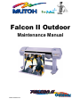
Falcon II Outdoor
Maintenance Manual
Mutoh America Inc.
Falcon II Outdoor series printers – Maintenance Manual
COPYRIGHT NOTICE
COPYRIGHT © 2003 Mutoh America Inc. All rights reserved.
This document may not be reproduced by any means, in whole or in part, without written permission of the copyright owner.
This document is furnished to support the Mutoh’s Falcon II Outdoor series Printer. In consideration of the furnishing of the
information contained in this document, the party to whom it is given, assumes its custody and control and agrees to the
following:
The information herein contained is given in confidence, and any part thereof shall not be copied or reproduced without
written consent of Mutoh America Inc.
This document or the contents herein under no circumstances shall be used in the manufacture or reproduction of the
article shown and the delivery of this document shall not constitute any right or license to do so.
November 2003
Republished: Mutoh America Inc.,
2
AP-74065, Rev. 1.0, 21/11/03
Falcon II Outdoor series printers – Maintenance Manual
Important Notice
This product has been tested and found to comply with the limits for a Class A digital device, pursuant to Part 15 of FCC
Rules. These limits are designed to provide reasonable protection against harmful interference when the product is
operated in a commercial environment.
This product generates, uses, and can radiate radio frequency energy and if not installed and used in accordance with this
manual, may cause harmful interference to radio communications. Operation of this product in a residential area is likely to
cause harmful interference in which case the user will be required to correct the interference at his expense.
1.
Radio interfere
Product generates weak radio signals and may interfere with television reception and utilities. If a
product does interfere with radio or TV reception, try following:
2.
¾
Change the direction of your radio and TV reception antenna or feeder.
¾
Change the direction of the product.
¾
Move either the product or the receiving antenna so there is more distance between them.
¾
Be sure the product and the receiving antenna are on separate power lines.
Trademark mentioned in this manual.
¾
MUTOH, Falcon II Outdoor, Eco-Solvent Plus, MH-GL, MH-GL2, MH-RTL are registered trademarks
or product names of MUTOH INDUSTRIES LTD.
¾
Centronics and Bitronics are registered trademarks or product names of Centronics Data Computer
Corporation.
¾
Windows 95, Windows 98, Windows Me, Windows XP, Windows NT4.0, Windows2000, and
MSDOS are registered trademarks or product names of Microsoft Corporation.
¾
DOS/V is registered trademark and product name of International Business Machine Corporation
(IBM).
¾
Other company and product names may be registered trademarks or product names.
No part of this product or publication may be reproduced, copied or transmitted in any form or by any means, except for
personal use, without the permission of Mutoh America Inc.
The product and the contents of this publication may be changed without prior notification.
Mutoh America Inc. has made the best efforts to keep this publication free from error, but if you find any uncertainties or
misprints, please call us or the shop where you bought this equipment.
Mutoh America Inc. shall not be liable for any damages or troubles resulting from the use of this equipment or this manual.
3
AP-74065, Rev. 1.0, 21/11/03
Falcon II Outdoor series printers – Maintenance Manual
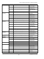
TABLE OF CONTENTS
1. Safety Instructions ......................................................................................................................... 11
1.1. Introduction............................................................................................................................. 11
1.2. Warnings, Cautions and Note ................................................................................................. 11
1.3. Important safety instructions................................................................................................... 11
1.3.1. Warning............................................................................................................................ 11
1.3.2. Caution............................................................................................................................. 12
1.4. Warning labels ........................................................................................................................ 13
1.4.1. Handling the operation procedure labels ......................................................................... 13
1.4.2. Locations and types of operation procedure labels.......................................................... 13
1.5. Operation procedure labels ..................................................................................................... 16
2. Product Overview .......................................................................................................................... 17
2.1. Introduction............................................................................................................................. 17
2.2. Features ................................................................................................................................... 17
2.3. Part names and functions ........................................................................................................ 18
2.3.1. Front................................................................................................................................. 18
2.3.2. Back ................................................................................................................................. 19
2.3.3. Operation panel................................................................................................................ 20
2.4. Printer status............................................................................................................................ 21
2.4.1. Normal ............................................................................................................................. 21
2.4.2. Setup menu display .......................................................................................................... 22
2.4.3. Self-diagnosis Function Display ...................................................................................... 22
2.4.4. Maintenance Mode Display ............................................................................................. 22
2.4.5. Selecting Language.......................................................................................................... 22
2.5. Position and function of the heating elements ........................................................................ 24
2.5.1. Falcon II Outdoor 2 heater printers.................................................................................. 24
2.5.2. Falcon II Outdoor 4 heater printers.................................................................................. 24
2.5.3. 2 or 4 heater ..................................................................................................................... 25
3. Specifications................................................................................................................................. 26
3.1. Introduction............................................................................................................................. 26
3.2. Product Specifications ............................................................................................................ 26
3.3. Interface Specifications........................................................................................................... 28
3.3.1. Centronics Bidirection Parallel Interface:IEEE1284)...................................................... 28
3.3.2. Network Interface (Optional) Specifications ................................................................... 29
3.4. Installation............................................................................................................................... 30
3.4.1. Conditions of the installation environment...................................................................... 30
4. Parts Replacement.......................................................................................................................... 32
4.1. Introduction............................................................................................................................. 32
4.2. Removing the cover ................................................................................................................ 33
4.2.1. Removing the I/H cover................................................................................................... 34
4.2.2. Removing side cover R.................................................................................................... 35
4.2.3. Removing side cover L .................................................................................................... 38
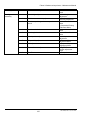
4
AP-74065, Rev. 1.0, 21/11/03
Falcon II Outdoor series printers – Maintenance Manual
4.2.4. Removing the front cover ................................................................................................ 41
4.2.5. Removing the carriage cover ........................................................................................... 43
4.2.6. Removing the panel unit assembly .................................................................................. 44
4.2.7. Removing the Y rail cover............................................................................................... 46
4.2.8. Removing front paper guide ............................................................................................ 48
4.2.9. Removing rear paper guide.............................................................................................. 50
4.2.10. Removing the head cover............................................................................................... 52
4.2.11. Removing the maintenance cover.................................................................................. 54
4.3. Replacement of the heater element ......................................................................................... 55
4.3.1. Falcon II Outdoor 2 heaters : Heater elements ................................................................ 55
4.3.2. Falcon II Outdoor 4 heaters : Heater elements ................................................................ 58
4.4. Replacing Board Bases ........................................................................................................... 67
4.4.1 Replacing the Mainboard assembly, HDD_Extension board assembly, HEAD_DRV board assembly,
PCI_Linux board assembly and cooling fan assembly .............................................................. 67
4.4.2. Replacing the power source board assembly ................................................................... 72
4.4.3. Replacing the inlet assembly, inlet board assembly and lever foot SW cable assembly. 74
4.4.4. Replacing the JUNCTION board assembly..................................................................... 75
4.5. Replacing the PF Actuator ...................................................................................................... 76
4.5.1. Replacing the PF motor assembly.................................................................................... 76
4.5.2. Replacing the PF_ENC assembly and PF scale assembly ............................................... 78
4.5.3. Replacing the PF deceleration pulley assembly............................................................... 80
4.5.4. Replacing the PF deceleration belt .................................................................................. 81
4.5.5. Replacing the P_REAR_R sensor assembly and P_REAR_L sensor assembly.............. 82
4.5.6. Replacing the suction fan assembly................................................................................. 83
4.5.7. Replacing the lever motor assembly and the arm motor installation board..................... 84
4.5.8. Replacing the transmission photosensor.......................................................................... 86
4.5.9. Replacing the flushing box assembly .............................................................................. 89
4.6. Replacing the CR Actuator ..................................................................................................... 90
4.6.1. Replacing the CR motor assembly................................................................................... 90
4.6.2. Replacing the steel belt .................................................................................................... 91
4.6.3. Replacing the SLIDE motor assembly, HD_SLIDE sensor assembly, and slide motor installation
board .......................................................................................................................................... 93
4.6.4. Replacing the T fence ...................................................................................................... 95
4.6.5. Replacing the CR slave pulley assembly ......................................................................... 98
4.6.6. Replacing the CR actuator pulley and the CR deceleration belt...................................... 99
4.6.7. Replacing the steel bearer, tube guide, CR tape power cable and ink tube ................... 100
4.6.8. Replace the cover R sensor assembly and the cover L sensor assembly ....................... 103
4.7. Replacing the Cursor............................................................................................................. 105
4.7.1. Replacing the cutter holder, cutter spring, cutter cap, solenoid assembly and solenoid spring 105
4.7.2. Replacing the print head assembly and head tape power cable ..................................... 108
4.7.3. Replacing the H ink tube, tube branch and damper assembly ....................................... 110
4.7.4. Replacing the CR board assembly ................................................................................. 112
4.7.5. Replacing the CR_ENC assembly ................................................................................. 114
4.7.6. Replacing the P_EDGE sensor assembly ...................................................................... 115
4.7.7. Replacing the CR cursor assembly ................................................................................ 116
5
AP-74065, Rev. 1.0, 21/11/03
Falcon II Outdoor series printers – Maintenance Manual
4.7.8. Replacing the cursor roller assembly............................................................................. 118
4.8. Replacing the Maintenance Area .......................................................................................... 122
4.8.1. Replacing the maintenance assembly ............................................................................ 122
4.8.2. Replacing the cleaner..................................................................................................... 126
4.8.3. Replacing the SLIDE motor assembly (wiper arm)....................................................... 127
4.8.4. Replacing the transmission photosensor (wiper home position and maintenance home position)
.................................................................................................................................................. 128
4.9. Replacing the Pump Area ..................................................................................................... 129
4.9.1. Replacing the pump assembly ....................................................................................... 129
4.9.2. Replacing the pump assembly ....................................................................................... 131
4.9.3. Replacing the pump motor assembly............................................................................. 132
4.10. Replacing the Cartridge Area.............................................................................................. 133
4.10.1. Replacing the I/H (ink holder) assembly ..................................................................... 133
4.11. Replacing Supports and Scroller......................................................................................... 137
4.11.1. Replacing the waste fluid bottle assembly (Falcon II Outdoor 2H) ............................ 137
4.11.2. Replacing the waste fluid bottle assembly (Falcon II Outdoor 4H) ............................ 138
4.11.3. Replacing the waste bottle box sensor assembly (F2O 2H) ........................................ 139
4.11.4. Replacing the waste bottle box sensor assembly (F2O 4H) ........................................ 141
4.11.5. Replacing the scroller R assembly............................................................................... 143
4.10.6. Replacing the scroller L assembly ............................................................................... 145
5. Self-Diagnosis Function............................................................................................................... 147
5.1. Introduction........................................................................................................................... 147
5.2. Preparation ............................................................................................................................ 147
5.2.1. Preparations on Machine................................................................................................ 147
5.2.2. Starting Up ..................................................................................................................... 148
5.3. Operations in Self-Diagnosis Mode...................................................................................... 149
5.3.1. Operating Self-Diagnosis Mode .................................................................................... 149
5.3.2. Diagnosis Items in Self-Diagnosis Menu ...................................................................... 151
5.4. Test / Inspection Menu.......................................................................................................... 152
5.4.1. Memory Size Menu........................................................................................................ 153
5.4.2. Version Menu................................................................................................................. 154
5.4.3. Operation Panel Menu ................................................................................................... 155
5.4.4. Sensor Menu .................................................................................................................. 156
5.4.5. Encoder Menu................................................................................................................ 158
5.4.6. Fan Menu ....................................................................................................................... 159
5.4.7. History Menu ................................................................................................................. 160
5.4.8. Head Signal Menu.......................................................................................................... 162
5.5. Adjustment Menu.................................................................................................................. 163
5.5.1. Skew Check Menu ......................................................................................................... 164
5.5.2. Head rank input menu.................................................................................................... 165
5.5.3 Head Nozzle Check Menu .............................................................................................. 167
5.5.4. Head Slant Check Menu ................................................................................................ 169
5.5.5. Repeatability Adjustment Menu .................................................................................... 173
5.5.6. CW Adjustment Menu ................................................................................................... 174
6
AP-74065, Rev. 1.0, 21/11/03
Falcon II Outdoor series printers – Maintenance Manual
5.5.7. Band Feed Correction Menu (X Length) ....................................................................... 175
5.5.8. Top & bottom adjustment menu .................................................................................... 177
5.5.9. P_REAR sensor position adjustment menu ................................................................... 179
5.5.10. Test print menu ............................................................................................................ 181
5.5.11. Head wash menu .......................................................................................................... 182
5.5.12. Software Counter Initialization Menu ......................................................................... 184
5.5.13. Feed Pitch Check Menu ............................................................................................... 185
5.5.14. Fill printing menu ........................................................................................................ 186
5.6. Purge Menu........................................................................................................................... 187
5.7. Sample Printing Menu .......................................................................................................... 188
5.8. Parameter Menu .................................................................................................................... 189
5.8.1. Parameter Initialization Menu........................................................................................ 189
5.8.2. Parameter Update Menu ................................................................................................ 190
5.9. Endurance Running Menu .................................................................................................... 197
5.9.1. CR Motor Endurance Menu........................................................................................... 198
5.9.2. PF Motor Endurance Menu............................................................................................ 199
5.9.3. Cutter Endurance menu.................................................................................................. 200
5.9.4. Head Up/Down Endurance Menu.................................................................................. 202
5.9.5. Head Lock Endurance menu.......................................................................................... 203
5.9.6. Pump Endurance menu .................................................................................................. 204
5.9.7. Lever Motor Endurance Menu....................................................................................... 205
5.9.8. Sequential Printing Endurance Menu ............................................................................ 206
5.9.9. General Endurance Menu .............................................................................................. 208
5.9.10. Endurance Running Check Menu ................................................................................ 210
5.10. Head Lock Menu................................................................................................................. 211
5.11. Heater System menu ........................................................................................................... 212
5.11.1. Heater Status Menu...................................................................................................... 212
5.11.2. Heater Temperature Menu ........................................................................................... 212
5.11.3. Heater Test 30 Menu.................................................................................................... 213
5.11.4. Heater Test 50 Menu.................................................................................................... 213
5.11.5. Heater Test Max Menu ................................................................................................ 213
5.11.6. Heater Version Menu................................................................................................... 214
5.11.7. Heater Adjust Menu..................................................................................................... 214
5.12. Eco Prepare menu ............................................................................................................... 214
5.13. Machine size select menu ................................................................................................... 215
6. Maintenance Mode....................................................................................................................... 216
6.1. Introduction........................................................................................................................... 216
6.2. Operating Maintenance Mode............................................................................................... 216
6.2.1. Starting Up Maintenance Mode ..................................................................................... 216
6.2.2. Operating Maintenance Mode........................................................................................ 217
6.3. Maintenance Menu................................................................................................................ 218
6.3.1. Counter Display Menu................................................................................................... 218
6.3.2. Counter Initialization Menu........................................................................................... 221
7
AP-74065, Rev. 1.0, 21/11/03
Falcon II Outdoor series printers – Maintenance Manual
6.3.3. MAC address write enable menu................................................................................... 222
7. Adjustments ................................................................................................................................. 224
7.1. Introduction........................................................................................................................... 224
7.2. Adjustment............................................................................................................................ 225
7.3. Parameter backup.................................................................................................................. 228
7.3.1. Tools required for work ................................................................................................. 228
7.3.2. Procedure for creating backup parameters..................................................................... 229
7.3.3. Backup parameter installation procedure....................................................................... 230
7.4. Firmware installation ............................................................................................................ 231
7.4.1. Tools required for work ................................................................................................. 232
7.4.2. Installation procedure..................................................................................................... 232
7.5. Steel belt tension adjustment ................................................................................................ 236
7.5.1. Tools required for work ................................................................................................. 236
7.6. PF deceleration belt tension adjustment ............................................................................... 238
7.6.1. Tools required for work ................................................................................................. 238
7.6.2. Adjustment Procedure.................................................................................................... 238
7.7. Head precision adjustment.................................................................................................... 239
7.7.1. Head angle adjustment................................................................................................... 239
7.7.2. Front and back of head adjustment ................................................................................ 240
7.8. Repeatability Adjustment...................................................................................................... 243
7.9. CW adjustment...................................................................................................................... 245
7.10. CR deceleration belt tension adjustment............................................................................. 246
7.10.1. Tools required for work ............................................................................................... 246
7.10.2. Adjustment Procedure.................................................................................................. 246
7.11. Cover sensor adjustment ..................................................................................................... 247
7.12. Head height adjustment....................................................................................................... 249
7.12.1. Tools required for work ............................................................................................... 249
7.12.2. Adjustment Procedure.................................................................................................. 249
7.13. Media sensor sensitivity adjustment ................................................................................... 251
7.13.1. Tools required for work ............................................................................................... 251
7.13.2. Adjustment Procedure.................................................................................................. 251
7.14. Cutter adjustment ................................................................................................................ 254
7.15. Pump tubing layout for pump assembly ............................................................................. 256
7.15.1. Replacing the pump assembly (Rockhopper 4 heater) ................................................ 256
7.15.2. Replacing the pump assembly (Rockhopper 2 heater) ................................................ 259
8. Maintenance................................................................................................................................. 266
8.1. Introduction........................................................................................................................... 266
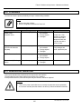
8.2. Cleaning ................................................................................................................................ 267
8.3. Periodical Services................................................................................................................ 267
8.3.1. Service by end-user........................................................................................................ 268
8.3.2. Service by authorised Mutoh technician........................................................................ 268
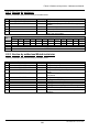
8.4. Part Life Information ............................................................................................................ 269
8
AP-74065, Rev. 1.0, 21/11/03
Falcon II Outdoor series printers – Maintenance Manual
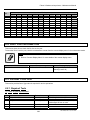
8.5. Jig and Tool List ................................................................................................................... 269
8.5.1. Required Tools............................................................................................................... 269
8.6. Lubrication/Bonding ............................................................................................................. 271
8.7. Transportation of Machine.................................................................................................... 274
9. Troubleshooting ........................................................................................................................... 276
9.1. Introduction........................................................................................................................... 276
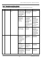
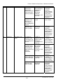
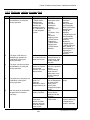
9.2. Troubleshooting procedures when a message has been displayed ....................................... 276
9.2.1. Operating condition display........................................................................................... 277
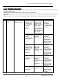
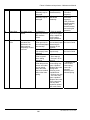
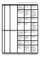
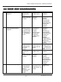
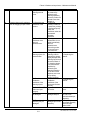
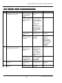
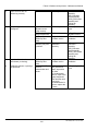
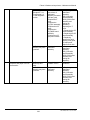
9.2.2. Message type errors ....................................................................................................... 279
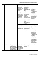
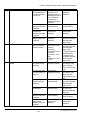
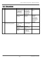
9.2.3. Heating system error ...................................................................................................... 286
9.2.4. Data error ....................................................................................................................... 288
9.2.5. Command errors............................................................................................................. 289
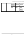
9.2.6. Errors requiring restart................................................................................................... 290
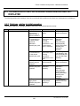
9.3. Troubleshooting procedures when errors are not displayed ................................................. 302
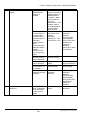
9.3.1. Problems relating to initial operation............................................................................. 302
9.3.2. Problems relating to paper feed ..................................................................................... 308
9.3.3. Problems relating to the printing operation ................................................................... 310
9.3.4. Problems relating to noise.............................................................................................. 323
9.3.5. Problems relating to the paper cutting operation ........................................................... 326
9.3.6. Problems relating to online and functions ..................................................................... 330
9.3.7. Other problems............................................................................................................... 333
10. Appendix .................................................................................................................................... 334
10.1. Introduction......................................................................................................................... 334
10.2. Wiring Diagram Falcon II Outdoor 2H............................................................................... 334
10.3. Wiring Diagram Falcon II Outdoor 4H............................................................................... 336
10.4. Falcon II Outdoor : Service Parts List/Exploded Views/Configuration Diagrams............. 338
10.4.1. Board Components....................................................................................................... 338
10.4.2. Cartridge Components ................................................................................................. 339
10.4.3. Cover Components....................................................................................................... 340
10.4.4. Cursor Components ..................................................................................................... 341
10.4.5. CR Driving components .............................................................................................. 342
10.4.6. Maintenance Components............................................................................................ 343
10.4.7. PF Driving Components .............................................................................................. 344
10.4.8. Paper Guide Front Components................................................................................... 345
10.4.9. Paper Guide Rear components..................................................................................... 346
10.4.10. Panel components ...................................................................................................... 346
10.4.11. Leg Section ................................................................................................................ 346
10.4.12. Pump Components ..................................................................................................... 347
10.4.13. Scroller L Components .............................................................................................. 347
10.4.14. Scroller R Components .............................................................................................. 347
10.4.15. Take-up....................................................................................................................... 348
10.4.16. Fan Part Plate PCB..................................................................................................... 348
10.4.17. Print Platform............................................................................................................. 349
9
AP-74065, Rev. 1.0, 21/11/03
Falcon II Outdoor series printers – Maintenance Manual
10.4.18. Waste bottle................................................................................................................ 349
10
AP-74065, Rev. 1.0, 21/11/03
Falcon II Outdoor series printers – Maintenance Manual
1. SAFETY INSTRUCTIONS
1.1. INTRODUCTION
This chapter explains the meaning of safety terms for personnel who operate this equipment, important safety instructions
and the positions of the warning labels.
Important :
•
Be sure to follow all instructions and warnings in this manual when using the
equipment.
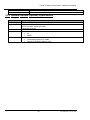
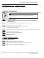
1.2. WARNINGS, CAUTIONS AND NOTE
Safety terms in this manual and the contents of warning labels attached to the printer are categorized into the following
three types depending on the degree of risk (or the scale of accident).
Read the following explanations carefully, and follow the instructions in this manual.
Safety terms
Important
Caution
Note
Details
Must be followed carefully to avoid death or serious bodily injury.
Must be observed to avoid bodily injury (moderately or lightly) or damage to your equipment.
Contains important information and useful tips on the operation of your printer.
1.3. IMPORTANT SAFETY INSTRUCTIONS
General safety instructions that must be observed to use the equipment safely are explained below.
1.3.1. Warning
¾
Do not place the printer in following areas. Doing so may result in the printer falling over and causing injury.
Angled place.
Areas subject to vibration by other equipment.
Do not stand on the printer or place heavy objects on the printer.
¾
Do not sit on the printer. Doing so may cause the printer to fall and injure people.
¾
Do not cover the ventilation hole of the printer with cloth, such as a blanket or table cloth. Doing so could obstruct
ventilation and cause fire.
¾
Do not place the printer in humid and dusty areas. Doing so may result in electrical shock or fire.
11
AP-74065, Rev. 1.0, 21/11/03
Falcon II Outdoor series printers – Maintenance Manual
¾
Be sure that the following is performed before replacing parts.
Turn the printer off.
Disconnect the power cable from the electric outlet. Not doing so may cause electric shock or damage to the
electric circuit.
Unplug the cables connected to the printer.
1.3.2. Caution
¾
Assembling and disassembling the printer are possible only for the parts shown in the operation manual. Do not
disassemble any frame parts or parts of which disassembling procedures are not shown in the manual. Doing so may
cause trouble that cannot be restored, as the printer is originally assembled in the factory with a high accuracy of 1/100
mm.
¾
Do not touch the elements on the circuit board with bare hands. Doing so may cause static electricity and break the
elements.
¾
Do not press down the transparent film on the sides of the damper assembly with your hands. The damper assembly is
filled with ink and pressing on the film will make the ink spurt out.
¾
Be careful not to scratch the transparent film on the sides of the damper assembly.
¾
Be careful not to touch the surface of the print head’s nozzles or to let dirt adhere to them.
¾
There is some remaining ink in the tubes. Be careful that the ink is not spilled from the tube onto the printer or objects
close to the printer.
¾
If you need to operate the printer with the cover removed for maintenance, be careful not to get hurt by the moving
parts.
¾
Do not oil the printer mechanism with oil other than the oil designated by MUTOH. Doing so may damage the parts or
shorten the lifetime.
¾
If the power substrate assembly needs to be removed, disconnect the power cable and wait for at least 5 minutes
before taking it out. This will discharge the residual electrical charge of the electrolytic capacitor. Touching the
substrate before the capacitor discharges may cause electric shock.
¾
When connecting or disconnecting the FFC type cable from the connector of the main substrate assembly, be sure to
connect or disconnect the cable straight out from the connector. Connecting or disconnecting at a slant angle may
damage, break or short-circuit the inner terminal of the connector. That may damage the elements on the substrate.
¾
When connecting or disconnecting the FFC type cable from the connector of the CR substrate, be sure to connect or
disconnect the cable straight out from the connector. Connecting or disconnecting at a slant angle may damage, break
or short-circuit the inner terminal of the connector. That may damage the elements on the substrate.
¾
Before replacing parts, be sure to adjust the capping position. When the capping position adjustment has not been
implemented, the cleaning position and other operational positions can exit the alignment and normal operations
become impossible.
¾
Pay attention to the following points when performing the cutter endurance operation.
Install an available ink cartridge.
Make sure that media initialization has been completed.
¾
Make sure that the power of the printer is OFF before performing the parameter backup. Performing the parameter
backup with the power ON may damage the main substrate or data may not be properly installed.
12
AP-74065, Rev. 1.0, 21/11/03
Falcon II Outdoor series printers – Maintenance Manual
¾
Make sure that the power of the printer is OFF before installing the firmware. Installing the firmware with the power ON
may damage the main substrate assembly or data may not be properly installed.
¾
Ensure there is sufficient space around the printer when performing maintenance work.
¾
Maintenance must be done by more than one person for :
detaching the printer from the stand or attaching it.
packing the printer for transportation.
1.4. WARNING LABELS
The handling, attachment locations, and types of warning labels are explained below.
Warning labels are attached to areas to which attention should be paid. Read and understand the positions and contents
thoroughly.
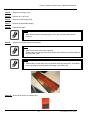
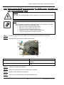
1.4.1. Handling the operation procedure labels
Notes :
Make sure that all labels can be recognized. If text or illustrations are invisible,
clean or replace the label.
¾ When cleaning labels, use a cloth with water or neutral detergent. Do not use a
solvent or gasoline.
¾ If a warning label has been damaged, lost or cannot be recognized, replace the
label.
¾
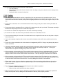
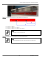
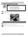
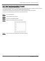
1.4.2. Locations and types of operation procedure labels
The locations of warning labels are shown below.
(1) Front Part
13
AP-74065, Rev. 1.0, 21/11/03
Falcon II Outdoor series printers – Maintenance Manual
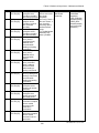
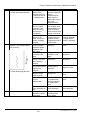
No.
1
Type
CAUTION
VORSICHT
ATTENTION
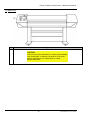
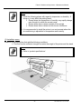
> Do not open the front cover or touch the media during printing.This will result in poor image quality.
> If no printing is to be done for some time, remove the media and put the hold lever in the up
position. Otherwise the media may lift up and become wrinkled and you will not be able to obtain
good printing results.
> Öffnen Sie wärhend des Druckens die Frontabdeckung nicht und berühren Sie das
Druckmaterial nicht.
> Wenn Sie wärhend längere Zeit den Drucker nicht benutzen, nehmen Sie das Druckmaterial
heraus und stellen Sie den Halthebel in die obersten Position. Sonst kann sich das Druckmaterial
aufheben und zerknittern und demzufolge erzielen Sie keine gute Druckergebnisse mehr.
> N'ouvrez pas le couvercle quand l'imprimante est en train d'imprimer. Ne touchez pas non plus
le papier afin d'éviter que la qualité s'aggrave.
> Si vous ne comptez pas imprimer pendant un certain temps, retirez le papier et mettez le levier
en position levée. Sinon, le support risque de se soulever et de se froisser et vous n'obtiendrez
pas de bonne qualité d'impression.
2
Only on a Falcon II Outdoor 2H printer
CAUTION
VORSICHT
ATTENTION
> To avoid injury, keep fingers away from the
cutter blade.
> Um Verletzungen zu vermeiden, berürhen Sie das
Schneidemesser nicht.
> Ne touchez pas la lame afin d'éviter des blessures.
> To avoid injury, do not touch the edge of the
steel belt.
> Um Verletzungen zu vermeiden, berühren Sie den
Stahl-Antriebsriemen nicht .
> Ne touchez pas la courroie de transmission en
acier afin d'éviter des blessures.
A
Only on a Falcon II Outdoor 4H printer
14
AP-74065, Rev. 1.0, 21/11/03
Falcon II Outdoor series printers – Maintenance Manual
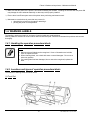
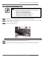
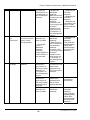
(2) Back Part
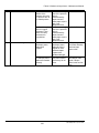
No.
3
Type
CAUTION
THIS UNIT HAS TWO POWER SUPPLY CORDS, WHEN WiNDING
UNIT IS PROVIDED. TO REDUCE THE RISK OF ELECTRICAL
SHOCK, DISCONNECT ALL POWER SUPPLY CORDS
BEFORE SERVICING.
15
AP-74065, Rev. 1.0, 21/11/03
Falcon II Outdoor series printers – Maintenance Manual
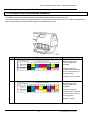
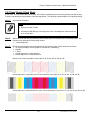
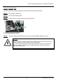
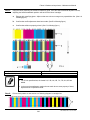
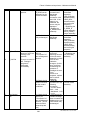
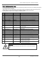
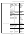
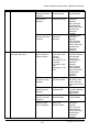
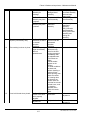
1.5. OPERATION PROCEDURE LABELS
The handling, attachment locations and types of operation procedure labels are explained below.
Your printer has labels, which give simple explanations of operations that require particular care. Read and understand the
locations and contents of these labels thoroughly before performing your work.
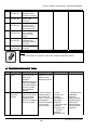
No.
6
Type
Number
of the
Colours
Ink Type
4
6
1
2
Eco Solvent
2x4 colours
Black
Yellow
Eco Solvent
1x6 colours
Black
Cyan
Refer to
Slot Number of Ink Cartridge
4
3
5
6
Cyan
Magenta Magenta
Transition Transition
Liquid
Liquid
Yellow
7
8
Cyan
Yellow
Black
Magenta
Light
Cyan
Light
Magenta
Æ Refer to the User’s
Guide “Installing ink
cartridges”
Please note that ink
cassettes order is different
for 87” printers versus 50”
and 64” printers.
(Label 50” and 64” printer)
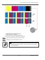
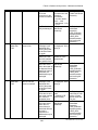
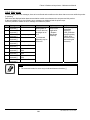
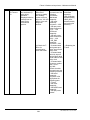
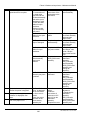
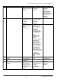
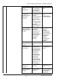
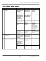
6
Number
of the
Colours
Ink Type
4
6
1
2
Eco Solvent
2x4 colours
Black
Cyan
Eco Solvent
1x6 colours
Black
Slot Number of Ink Cartridge
4
3
5
6
Magenta
Yellow
Black
Cyan Transition Transition Yellow
Liquid
Liquid
Cyan
Magenta
7
8
Magenta Yellow
Light
Cyan
Light
Magenta
Æ Refer to the User’s
Guide “Installing ink
cartridges”
Please note that ink
cassettes order is different
for 87” printers versus 50”
and 64” printers.
(Label 87” printer)
16
AP-74065, Rev. 1.0, 21/11/03
Falcon II Outdoor series printers – Maintenance Manual
2. PRODUCT OVERVIEW
2.1. INTRODUCTION
This chapter explains the features, part names, and functions of the printer.
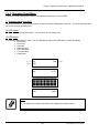
2.2. FEATURES
The features of the printer are explained below.
(1) High speed output
Both models feature new print heads and achieve high speed printing.
They also offer printing widths up to 1263 mm in 50-inch, 1643 mm in 64-inch and 2230 mm in 87-inch spec possible.
(2) Wide variety of compatible media
Adjustable head height can adapt to various media thickness from 0.08 up to 1.1 mm.
(3) Vibrant Colour Reproduction
To reproduce sharp and vivid colour, 4, 6 and 8 ink colours are used for printing. The 220ml large capacity ink
tank is equipped with an IC chip. This unit can automatically detect the ink quantity, significantly improving
productivity.
(4) Effective usage of media
A JOG feature is provided to allow setting of the printing position as required. Because printing can be
performed on media on which was already printed, excess space can be used effectively.
(5) RIP
Software Starter Pack included in-the-box. (To be defined with the order.)
17
AP-74065, Rev. 1.0, 21/11/03
Falcon II Outdoor series printers – Maintenance Manual
2.3. PART NAMES AND FUNCTIONS
Part names and functions are explained below.
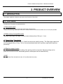
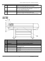
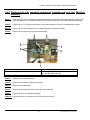
2.3.1. Front
No.
1
Name
Operation panel
2
3
Ink compartment
Front cover
4
Pressure rollers
5
Maintenance cover
6
Stand
Function
This panel is used to set operational conditions, the status of the printer,
and other functions.
This is the place for installing ink cartridges.
This cover keeps the operator safe from the drive parts of the printer
while it is operating. Only open and/or close the cover to perform
following operations:
¾ Media setting and replacement
¾ Cutter blade replacement
¾ Cleaning the cleaning wiper
¾ In case of media jam.
This roller is used to press the media from above and keep it flat when
printing.
This protects users from electric shocks caused by touching the internal
electrical parts. The cover is opened when expansion memory
(optional) has to be installed, and is closed for normal use.
This stand is used to install the printer on a surface flat floor.
The following options are available for installation.
¾ Take-up system + scroller receiver
¾ Motorized roll-off / roll-up system
18
AP-74065, Rev. 1.0, 21/11/03
Falcon II Outdoor series printers – Maintenance Manual
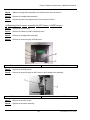
7
Media cut groove
8
Carriage cover
9
10
Foot switch
Paper Guide
Only onto the Falcon II Outdoor 4H printer !
Used to cut the media straight when it is cut manually.
Only onto the Falcon II Outdoor printer !
This is a cover to protect the user from the internal components of the
unit. This is opened during following operation :
¾ When cleaning the cleaning wiper
This switch is used to raise and lower the pressure rollers.
Support the media during printing
In the Falcon II Outdoor it houses post-heater (dryer).
In the Falcon II Outdoor 4H it houses the fixer, post-fixer and dryer.
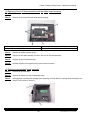
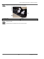
2.3.2. Back
No.
1
2
3
4
5
6
7
8
Name
AC inlet
Interface connector
Foot switch connector
Insertion slot
Interface slot 1
Interface slot 2
Interface slot 3
Hard disk slot
9
Nameplate rating
10
Rear Heater
Function
This is the inlet interface to which the power plug is connected.
This is the connector to which the interface cable is connected.
This is the connector to which the foot switch cable is attached.
This is the slot for inserting media when loading it.
The network interface board attaches here.
This is not used for this printer.
Close it with the cover.
The hard disk attaches here. When not using a hard disk, keep the
cover closed.
The type, name, serial number, rating and other details of the printer are
labelled here.
Supports the media during printing and houses the pre-heaters.
19
AP-74065, Rev. 1.0, 21/11/03
Falcon II Outdoor series printers – Maintenance Manual
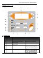
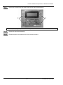
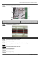
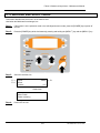
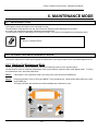
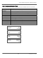
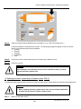
2.3.3. Operation panel
The operation panel is used to set operation conditions, display the status of the printer and set other functions.
The names and functions of the operation keys and status lamps are explained below.
(1) Operation Keys.
No.
1
2
3
4
5
6
Name
[POWER] key
[F1] key
[F2] key
[F3] key
[F4] key
[MENU ↑] key
7
[MENU ↓] key
8
[ENTER] key
Normal
Turns the printer on and off.
Executes the function assigned to F1.
Executes the function assigned to F2.
Executes the function assigned to F3.
Executes the function assigned to F4.
Changes the LCD monitor display to
setup menu status.
Changes the LCD monitor display to
setup menu status.
Displays the print mode currently set.
9
[CANCEL] key
-
20
Setup menu display
Turns the printer on and off.
Executes the function assigned to F1.
Executes the function assigned to F2.
Executes the function assigned to F3.
Executes the function assigned to F4.
Changes the menu in reverse order.
Changes the menu in forward order.
Determines the new parameter value and
changes the LCD monitor display to the
next menu. Sets the parameter value and
changes the LCD monitor display to the
next menu.
Cancels the new parameter value and
changes the LCD monitor display to the
next menu. Clears the parameter value
and changes the LCD monitor display to
AP-74065, Rev. 1.0, 21/11/03
Falcon II Outdoor series printers – Maintenance Manual
the next menu.
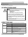
(2) LCD monitor and status lamps.
No.
10
Name
LCD monitor
Colour
-
11
POWER lamp
Green
12
ERROR lamp
Red
13
DATA lamp
Orange
14
MEDIA SET lamp
Orange
Status
ON
OFF
Flashing
OFF
ON
Flashing
OFF
ON
OFF
15
ROLL lamp
Orange
16
SHEET lamp
Orange
17
HEATER lamp
Orange
ON
OFF
ON
OFF
ON
Flashing
OFF
Function
The monitor displays the operation status and error
messages of the printer.
The printer is on.
The printer is off.
An error has occurred. The contents will be displayed on
the LCD monitor.
Either there is no error or the power is off.
The printer is receiving print data.
The printer is analysing receiving data.
The printer is waiting to receive print data.
¾ The pressure rollers are in the release position.
¾ Media is not set.
¾ The pressure rollers are in secured position.
¾ The media is set.
The media type is set to roll media.
The media type is set to sheet media.
The media type is set to sheet media.
The media type is set to roll media.
The temperature of the heating elements is the requested
temperature.
The real temperature is the same as the requested
temperature.
The heating elements are warming up.
The real temperature is different as the requested
temperature.
The heating elements are powered OFF.
2.4. PRINTER STATUS
The status of the printer is explained below.
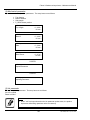
2.4.1. Normal
Indicates that the printer can print when media is loaded.
You can also make settings using the operation panel.
Notes :
¾
Refer to the User’s Guide.
21
AP-74065, Rev. 1.0, 21/11/03
Falcon II Outdoor series printers – Maintenance Manual
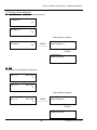
2.4.2. Setup menu display
Indicates that you can make settings using the operation panel.
Operations for printing can be conducted with the operation panel.
Notes :
¾
Refer to the User’s Guide.
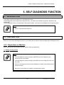
2.4.3. Self-diagnosis Function Display
Indicates that you can make settings concerning adjusting the printer using the operation panel. Keys of the operation
panel have the same names and functions as the display status of the setup menu.
Notes :
¾
Refer to the chapter “Self-Diagnosis function”.
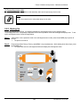
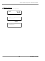
2.4.4. Maintenance Mode Display
Indicates that you can make settings concerning the life of the printer. Keys of the operation panel have the same names
and functions as the display status of the setup menu.
Notes :
¾
Refer to the chapter “Maintenance mode”.
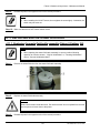
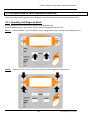
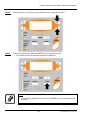
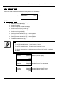
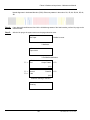
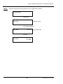
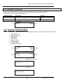
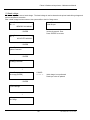
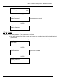
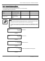
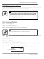
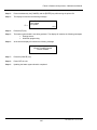
2.4.5. Selecting Language
This chapter explains how to select the language on the display.
Japanese or English is selectable for the display language of the printer.
Follow the steps below to select the display language.
Step 1 :
Press the [POWER] key while pressing the [CANCEL] key on the operation panel.
22
AP-74065, Rev. 1.0, 21/11/03
Falcon II Outdoor series printers – Maintenance Manual
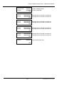
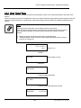
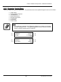
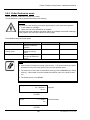
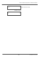
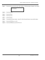
Step 2 :
Press the [F1] key or [F2] key on the operation panel to change the parameter.
Step 3 :
Press the [POWER] key, and then press the [POWER] key again.
23
AP-74065, Rev. 1.0, 21/11/03
Falcon II Outdoor series printers – Maintenance Manual
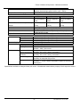
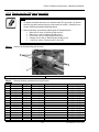
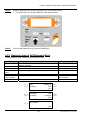
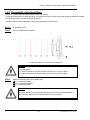
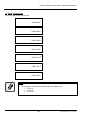
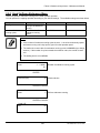
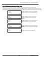
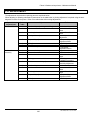
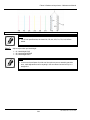
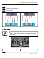
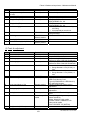
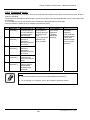
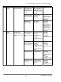
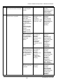
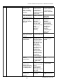
2.5. POSITION AND FUNCTION OF THE HEATING ELEMENTS
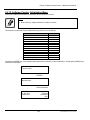
2.5.1. Falcon II Outdoor 2 heater printers
Heater element
Pre-heater (Heater A)
Temperature
20 – 50°C
Function
→ Open the pores to make the media more receptive for
eco-solvent or eco-solvent plus™ ink.
Dryer (Heater D)
20 – 50°C
→ Applying heating immediately after printing improves
ink/media anchorage.
→ The dryer helps to make the media touch-dry before it
reaches the automatic take-up system.
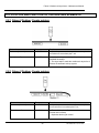
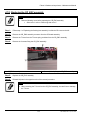
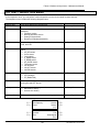
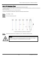
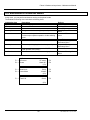
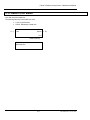
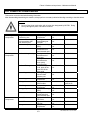
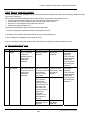
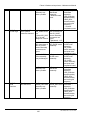
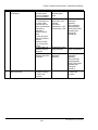
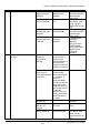
2.5.2. Falcon II Outdoor 4 heater printers
Heater element
Pre-heater (Heater A)
Temperature
20 – 50°C
Function
→ Open the pores to make the media more receptive
for eco-solvent or eco-solvent plus™ ink.
Fixer (Heater B)
20 – 70°C
→ To establish optimum fixation onto the media
(coated and uncoated).
→ Optimizes the dot gain control.
24
AP-74065, Rev. 1.0, 21/11/03
Falcon II Outdoor series printers – Maintenance Manual
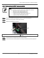
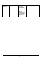
Post-Fixer (Heater C)
20 – 70°C
→ The post-fixer finalizes the fixation process and
helps to make the prints touch-dry.
Dryer (Heater D)
20 – 50°C
→ The dryer completes the drying for compatibility
with the take-up in combination with higher output
speeds.
→ Stickiness of printed banner materials is improved.
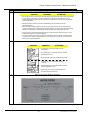
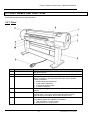
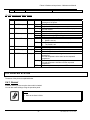
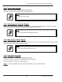
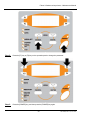
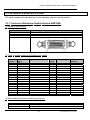
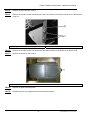
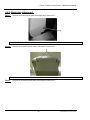
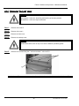
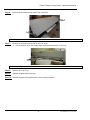
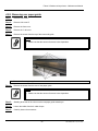
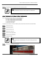
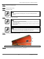
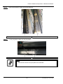
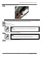
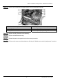
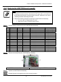
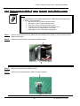
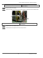
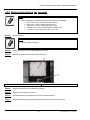
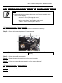
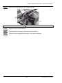
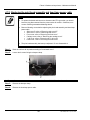
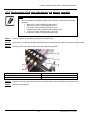
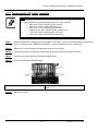
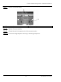
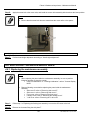
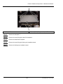
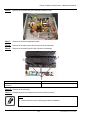
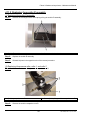
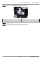
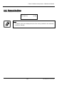
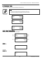
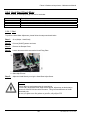
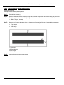
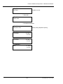
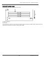
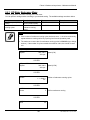
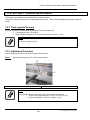
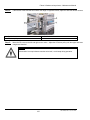
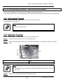
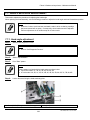
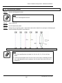
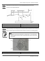
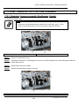
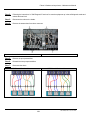
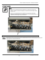
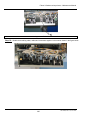
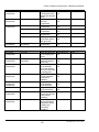
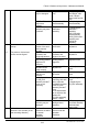
2.5.3. 2 or 4 heater
To verify if your printer is equipped with 2 or 4 heaters, please refer to the photo’s mentioned below.
Falcon II Outdoor 2 heater printer
Falcon II Outdoor 4 heater printer
25
AP-74065, Rev. 1.0, 21/11/03
Falcon II Outdoor series printers – Maintenance Manual
3. SPECIFICATIONS
3.1. INTRODUCTION
This section explains the specifications, optional parts and supplies, installation procedures for optional
parts, and user support for this printer.
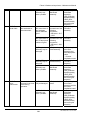
3.2. PRODUCT SPECIFICATIONS
Printers
Technology
Media Thickness Compensation
Maximum Media Widths
Maximum Print Widths
Media
Thickness
Diameter / Core
Weight
Colour Channels
Inks
Ink Cassette Capacity / Type
Print Modes & Panel Control Options
50”- model
64”- model
87”- model
Drop-on-demand Micro Piezo Inkjet Technology.
Variable drop mass output between 5.4 ng and 41.5 ng
Automatic media thickness compensation.
Variable – RIP controlled – Head Height
1273 mm
1653 mm
2240 mm
1263 mm
1643 mm
2230 mm
Range: 0.08 mm – 1.1 mm
Maximum: 150 mm / 2” or 3”
Maximum: 50 kg
8 colour channels – 4 or 6 process colour output
Eco-Solvent (Plus) 2xCMYK speed set-up
Eco-Solvent (Plus) CMYKLcLm photo tone rendering set-up
220 ml / smart chip ink type & order sensing
Uni & Bi-directional output, Interweaving, Mirror Output, Multi
Copy, Ink Status, Origin Control
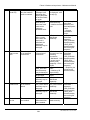
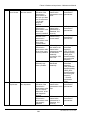
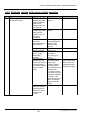
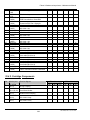
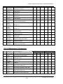
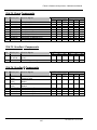
Speed Overview Table ( * )
50 & 64
87
914mm (36”) wide output
Ink Set-Up
2 x 4 Colours
6 Colours
2 x 4 Colours
6 Colours
360 x 360
5.7 – 37.7
2.9 – 19.6
5.7 – 37.7
3.9 – 27.7
{{{
{
720 x 360
5.8 – 22.8
2.9 – 11.5
5.9 – 23.1
5.3 – 20.6
{
720 x 720
2.9 – 11.4
1.4 – 5.6
2.9 – 11.5
2.6 – 10.2
{{{
{
1440 x 720
2.9 – 5.9
1.4 – 2.8
3.0 – 6.0
2.6 – 5.2
{
1440 x 1440
1.4 – 2.9
0.7 – 1.5
1.5 – 3.0
1.3 – 2.6
{
Output speeds are given for 914 mm (36”) output.
50” output is 7 % faster, 64” output is 12 % faster and 87” output is 18 % faster.
For each mode, the minimum (Super High Quality) and maximum speed (Super Draft) are given.
Mode dependent, there are between 2 and 6 speed levels per mode, accessible via print direction selection
and interweave control from the RIP software.
Top speeds indicated are super draft modes and do not guarantee production output quality on all media
types.
{{{ Variable Drop Compatible
{ Fixed Drop Compatible
LCD Display
Backlight LED – 4 lines x 20 characters
Take-up System (standard)
Automated
Roll Media Core
2” & 3”
26
AP-74065, Rev. 1.0, 21/11/03
Falcon II Outdoor series printers – Maintenance Manual
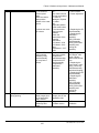
Interface
Graphics Command Language
Printers
Power Consumption
External Dimensions in mm (W x D x H)
Weight
Noise Level
Standard
Standard Items
50”- model
1100 VA
80 VA in stand-by
mode
2700 x 750 x 1250
64”- model
1300 VA
80 VA in stand-by
mode
3100 x 750 x 1250
87”- model
1400 VA
100 VA in stand-by
mode
3700 x 750 x 1250
170 kg
195 kg
215 kg
Operating: 54 dB or less
VCCI (Class A), FCC (Class A), UL, CE, CCIB
Hard Disk: 20.3 GB – Stores 16 jobs – Up to 99 copies/job –
PostScript RIP included
Extra Scroller Bars – Take-up System – Roll-off / roll-up system
Optional Item
Area
50” model
64” model
87” model
Floor loading capability
Electrical
Voltage
Frequency
Capacity
Environmental
Centronics, IEEE 1284 compatible / Network, High Speed
Interface (standard high-speed interface card – 4 Mb/s).
RTL-PASS, MH-GL, MH-GL/2
Recommended
working environment
Operational
conditions
Rate of change
Storage environment
11.7 m² or larger. Frontage of 4.3 m or greater.
12.7 m² or larger. Frontage of 4.7 m or greater.
14.3 m² or larger. Frontage of 5.3 m or greater.
2490Pa (300kg/m²) or over
AC100V - 120V or AC220V – 240V
50/60Hz±1Hz
AC100V - 120V: 3A or more
AC220V - 240V: 1.5A or more
Temperature: 25°C
Humidity: 40% to 60%, without condensation
Temperature: 18°C to 35°C
Humidity: 40% to 60%, without condensation
Temperature: No more than 2°C per hour
Humidity: No more than 5% per hour
Temperature: -20°C to 60°C
Humidity: 5 to 85%, without condensation (When ink has been
discharged.)
Specifications are liable to changes without prior notice. All trademarks mentioned are property of their respective owners.
27
AP-74065, Rev. 1.0, 21/11/03
Falcon II Outdoor series printers – Maintenance Manual
3.3. INTERFACE SPECIFICATIONS
This section explains the specifications for the interfaces supported by this product.
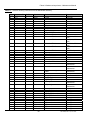
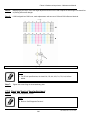
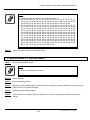
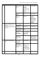
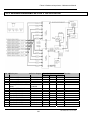
3.3.1. Centronics Bidirection Parallel Interface:IEEE1284)
(1) Interface Specifications
AP-74065, Rev : 1.0, 21/11/2003
Item
Transmission modes
Data length
Transmission direction
Connector pin number
Specifications
Compatible , Nibble , ECP Mode
8 bits
Unidirectional (receiving only), Bidirectional
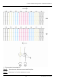
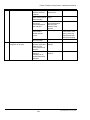
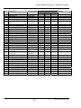
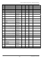
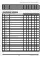
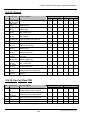
(2) Table of parallel interface pin numbers and signals
Pin
number
1
2
3
4
5
6
7
8
9
10
11
12
13
14
15
16
17
18
Connection
signal
STROBE
DATA1
DATA2
DATA3
DATA4
DATA5
DATA6
DATA7
DATA8
ACK
BUSY
P ERROR
SELECTED
AUTOFD
Not connected
SG
FG
+5V
Signal direction
To printer Å
To and from printer Å Æ
To and from printer Å Æ
To and from printer Å Æ
To and from printer Å Æ
To and from printer Å Æ
To and from printer Å Æ
To and from printer Å Æ
To and from printer Å Æ
From printer Æ
From printer Æ
From printer Æ
From printer Æ
To printer Å
Pin
number
19
20
21
22
23
24
25
26
27
28
29
30
31
32
33
34
35
36
Connection signal
SG
SG
SG
SG
SG
SG
SG
SG
SG
SG
SG
SG
INIT
FAULT
Not connected
Not connected
Not connected
SELECTIN
Signal
direction
To printer Å
From printer Æ
To printer Å
(3) Recommended Centronics cable specifications
Item
Interface
Structure
Specifications
Dual-direction Parallel Interface:IEEE1284
AWG28×18 (twisted pair wiring)
28
AP-74065, Rev. 1.0, 21/11/03
Falcon II Outdoor series printers – Maintenance Manual
Shield construction
Characteristic impedance
Metallic tape + weaving (double shielded cable)
62 Ω
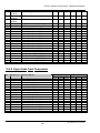
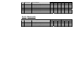
3.3.2. Network Interface (Optional) Specifications
Item
NetWork Type
NetWork I/F
Protocol
Mode
Functions
Specifications
Ethernet IEEE802.3
10 Base-T,100 Base-TX
(RJ-45 connector, twisted pair cable)
* Automatic switching
TCP/IP
• ftp
• lpr
• socket
• Automatic protocol recognition
• Transmission speed up to 4 MB/s
• Network environment setting by Web.
29
AP-74065, Rev. 1.0, 21/11/03
Falcon II Outdoor series printers – Maintenance Manual
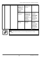
3.4. INSTALLATION
The Installation of the unit is explained below.
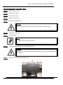
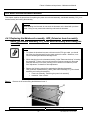
3.4.1. Conditions of the installation environment
Important :
¾ Do not place the printer in following areas. Doing so may result
in the printer falling over and causing injury.
Unstable surfaces
Slanted place
Where vibration of other machines is transmitted.
¾ Do not sit on the printer or put heavy things on the printer.
Doing so may cause the printer to fall and injure people.
¾ Do not cover the ventilation hole of the printer with cloth, such
as a blanket or table cloth. Doing so could obstruct ventilation
and cause fire.
¾ Do not place the printer in humid and dusty areas. Doing so may
result in electrical shock or fire.
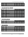
(1) Conditions of the installation environment
Select the place to install this unit according to the environmental condition in the table below.
Area
50” model
64” model
87” model
Floor loading capability
Electrical
Voltage
Frequency
Capacity
Environmental
Recommended
working environment
Operational conditions
Rate of change
Storage environment
11.7 m² or larger. Frontage of 4.3 m or greater.
12.7 m² or larger. Frontage of 4.7 m or greater.
14.3 m² or larger. Frontage of 5.3 m or greater.
2490Pa (300kg/m²) or over
AC100V - 120V or AC220V – 240V
50/60Hz±1Hz
AC100V - 120V: 3A or more
AC220V - 240V: 1.5A or more
Temperature: 25°C
Humidity: 40% to 60%, without condensation
Temperature: 18°C to 35°C
Humidity: 40% to 60%, without condensation
Temperature: No more than 2°C per hour
Humidity: No more than 5% per hour
Temperature: -20°C to 60°C
Humidity: 5 to 85%, without condensation (When ink has been
discharged.)
30
AP-74065, Rev. 1.0, 21/11/03
Falcon II Outdoor series printers – Maintenance Manual
Notes :
¾ Avoid the following places with regard to temperature or humidity. If
doing so, it may affect the printing result.
Places where the temperature of humidity may rapidly change
even though it is within the correct range.
Places where there is direct sunlight or strong light.
Places where there is direct air from the air conditioner.
¾ It is recommended to install the printer in an environment where the
air conditioning is adjustable for temperature and humidity.
(2) Installation space
Install on a horizontal place that satisfies following conditions.
¾ The floor has the sufficient strength to sustain the weight of the printer and the stand.
Notes :
¾ Refer to ‘product specifications’.
31
AP-74065, Rev. 1.0, 21/11/03
Falcon II Outdoor series printers – Maintenance Manual
4. PARTS REPLACEMENT
4.1. INTRODUCTION
This chapter explains the procedures for replacing and removing maintenance parts.
Important :
¾
Before replacing parts, be sure to perform following operations.
Turn the power OFF.
Remove the electrical cable from the socket. Otherwise, you may
suffer electric shock or the machine’s electric circuits may be
damaged.
Disconnect all cables from the machine. Not doing so could cause
damage to the printer.
Caution :
Assembling and disassembling the printer are possible only for the parts for which
disassembling procedures are shown in the operation manual.
Do not disassemble any frame parts or parts for which disassembling procedures are
not shown in the manual.
Doing so may cause trouble that cannot be restored, as the printer is originally
assembled in the factory with a high accuracy of 1/100 mm.
Notes :
¾
After replacing the parts, perform necessary lubrication/bonding according to
"Lubrication/Bonding".
32
AP-74065, Rev. 1.0, 21/11/03
Falcon II Outdoor series printers – Maintenance Manual
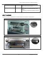
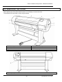
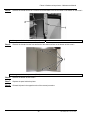
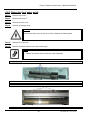
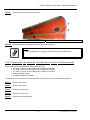
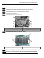
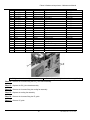
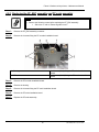
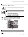
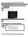
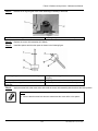
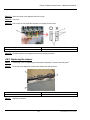
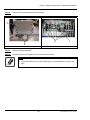
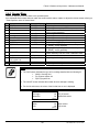
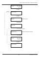
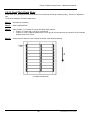
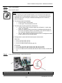
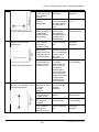
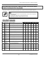
4.2. REMOVING THE COVER
When replacing any of the parts inside the printer, it is necessary to remove all covers.
The procedures for removing the covers are given below.
1 = I/H cover
2 = Side cover R
3 = side Cover L
4 = Front cover
5 = Panel unit assembly
6 = Y-rail cover
7 = Front paper guide
8 = Rear paper guide
33
AP-74065, Rev. 1.0, 21/11/03
Falcon II Outdoor series printers – Maintenance Manual
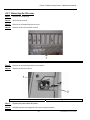
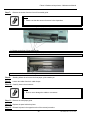
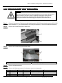
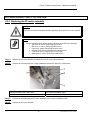
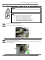
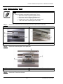
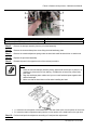
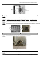
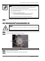
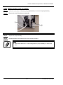
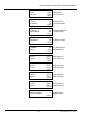
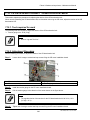
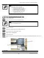
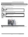
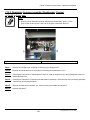
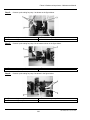
4.2.1. Removing the I/H cover
Step 1 :
Remove the ink cartridge.
Step 2 :
Open the I/H cover lid.
Step 3 :
Remove the 4 screws fixing the I/H cover.
Step 4 :
Remove the I/H cover and I/H cover lid.
1 = Screws (M3x12) fixing the I/H cover
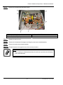
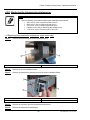
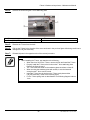
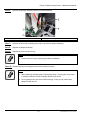
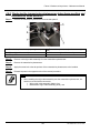
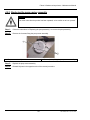
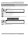
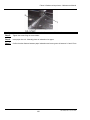
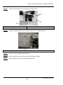
Step 5 :
Remove the 2 screws fixing the ink cover sensor.
Step 6 :
Remove the ink cover sensor.
1 = Ink cover sensor
2 = Screws (M2x10) fixing the ink cover sensor
Step 7 :
Replace the parts inside the printer.
Step 8 :
Reinstall all parts in the opposite order of the removal procedure.
34
AP-74065, Rev. 1.0, 21/11/03
Falcon II Outdoor series printers – Maintenance Manual
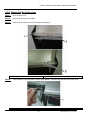
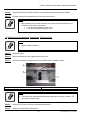
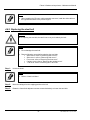
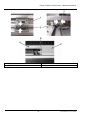
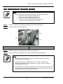
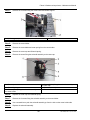
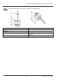
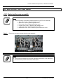
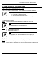
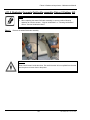
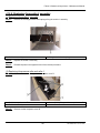
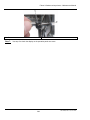
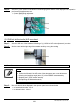
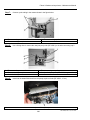
4.2.2. Removing side cover R
Step 1 :
Remove the screw from the upper part of the side cover R.
1 = Screws (M4x12) on the upper part of the side cover R
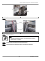
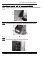
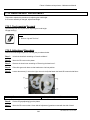
Step 2 :
Remove the 2 screws from the bottom of side cover R.
1 = Screws (M4x16) on the side of the bottom of side cover R
Step 3 :
Remove the 3 screws from the back of the bottom of side cover R.
35
AP-74065, Rev. 1.0, 21/11/03
Falcon II Outdoor series printers – Maintenance Manual
1 = Screws (M4x16) on the back of the bottom of side cover R
36
AP-74065, Rev. 1.0, 21/11/03
Falcon II Outdoor series printers – Maintenance Manual
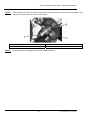
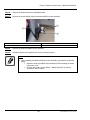
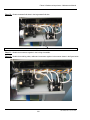
Step 4 :
Remove the top of the side cover R.
Step 5 :
Remove the 4 bolts from the front and back of the inner surface on the bottom of side cover R and the front
cover nut.
1 = Hexagon socket head cap screws (M4x16)
2 = Cover nut
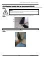
Step 6 :
Remove the 6 bolts from the front and back of the bottom surface on the bottom of the side cover R.
Step 7 :
Remove the bottom of side cover R.
1 = Hexagon socket head cap screws (M5x18)
Step 8 :
Replace the parts inside the printer.
Step 9 :
Reinstall all parts in the opposite order of the removal procedure.
37
AP-74065, Rev. 1.0, 21/11/03
Falcon II Outdoor series printers – Maintenance Manual
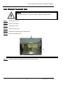
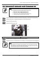
4.2.3. Removing side cover L
Step 1 :
Remove the screw from the side of the upper part of side cover L.
1 = Screws (M4x12) on the side of the upper part of the side cover L
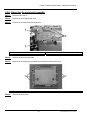
Step 2 :
Remove the 2 screws from the front of the bottom of side cover L.
1 = Screws (4x16) on the back of the bottom of side cover L
Step 3 :
Remove the 3 screws from the back of the bottom of side cover L.
38
AP-74065, Rev. 1.0, 21/11/03
Falcon II Outdoor series printers – Maintenance Manual
1 = Screws (M4x16) on the rear of the bottom part of the side cover L
39
AP-74065, Rev. 1.0, 21/11/03
Falcon II Outdoor series printers – Maintenance Manual
Step 4 :
Remove the 4 bolts and cover nut from the front and back of the inner surface on the bottom of side cover L.
1 = Hexagon socket head cap screws (M4x16)
Step 5 :
2 = Cover nut
Remove the 6 bolts from the front and back of the bottom surface on the bottom of side cover L.
1 = Hexagon socket head cap screws (M5x18)
Step 6 :
Remove the bottom of side cover L.
Step 7 :
Replace the parts inside the printer.
Step 8 :
Reinstall all parts in the opposite order of the removal procedure.
40
AP-74065, Rev. 1.0, 21/11/03
Falcon II Outdoor series printers – Maintenance Manual
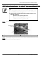
4.2.4. Removing the front cover
Step 1 :
Open the front cover.
Step 2 :
Remove the E ring on the left side.
Step 3 :
Remove the 4 screws on the left and right cover spindles.
1 = E ring
Step 4 :
2 = Screws (M3x8) on the left and right cover spindles
If the machine is a 50-inch model, remove cover spindle L, and then slide and remove the front cover.
1 = Cover spindle L
41
AP-74065, Rev. 1.0, 21/11/03
Falcon II Outdoor series printers – Maintenance Manual
Step 5 :
If the machine is 64 or 87-inch model, remove the E ring and the sensor cam, push the cover spindle L to the
origin side and then slide and remove the front cover.
1 = Cover spindle L
3 = E ring
Step 6 :
2 = Sensor cam
Reinstall all parts in the opposite order of the removal procedure.
42
AP-74065, Rev. 1.0, 21/11/03
Falcon II Outdoor series printers – Maintenance Manual
4.2.5. Removing the carriage cover
Caution :
Please note that this cover is only on a Falcon II Outdoor (2 heaters) printer.
Step 1 :
Remove the I/H cover.
Step 2 :
Remove side cover R.
Step 3 :
Remove side cover L.
Step 4 :
Remove the front cover.
Step 5 :
Remove the 4 screws fixing the carriage cover.
Step 6 :
Remove the carriage cover.
1 = Carriage cover
Step 7 :
2 = Screws (M3x6) fixing the carriage cover
Reinstall all parts in the opposite order of the removal procedure.
43
AP-74065, Rev. 1.0, 21/11/03
Falcon II Outdoor series printers – Maintenance Manual
4.2.6. Removing the panel unit assembly
Step 1 :
Remove side cover R.
Step 2 :
Remove the panel tape power cord.
Step 3 :
Remove the 4 screws fixing the panel base.
1 = Panel unit assembly
3 = Tape wire
2 = Screws (M3x6) fixing the panel unit assembly
Step 4 :
Remove the panel unit assembly.
Step 5 :
Remove the 6 screws fixing the panel board assembly and the panel cover.
1 = Screws (M3x8) fixing the panel cover
Step 6 :
Remove the panel cover.
44
AP-74065, Rev. 1.0, 21/11/03
Falcon II Outdoor series printers – Maintenance Manual
Step 7 :
Remove the 4 screws fixing the panel bracket and the panel board assembly.
1 = Screws (M3x8) fixing the panel board assembly
Step 8 :
Replace the panel board assembly.
Step 9 :
Reinstall all parts in the opposite order of the removal procedure.
45
AP-74065, Rev. 1.0, 21/11/03
Falcon II Outdoor series printers – Maintenance Manual
4.2.7. Removing the Y rail cover
Caution :
Removing the Y rail cover, should be performed by at least two persons.
Otherwise the Y rail cover may be deformed.
Step 1 :
Remove side cover R.
Step 2 :
Remove side cover L.
Step 3 :
Remove the front cover.
Step 4 :
Remove the carriage cover.
Caution :
Please note that this cover is only on a Falcon II Outdoor (2 heaters) printer.
Step 5 :
Remove the 3 screws fixing the Y rail cover and the Y rail cover FG.
1 = Y rail cover FG
2 = Screws (M3x6) fixing the Y rail cover and the Y rail cover FG
46
AP-74065, Rev. 1.0, 21/11/03
Falcon II Outdoor series printers – Maintenance Manual
Step 6 :
Remove the 6 screws from the front of the Y rail cover.
1 = Screws (M4x8) on the front of the Y rail cover
Step 7 :
Remove the 5 screws from the rear of the Y rail cover.
¾ If the machine is an 87-inch model, there are 8 screws on the rear Y rail cover.
1 = Screws (M4x8) on the rear of the Y rail cover
Step 8 :
Remove the Y rail cover.
Step 9 :
Replace the parts inside the printer.
Step 10 : Reinstall all parts in the opposite order of the removal procedure.
47
AP-74065, Rev. 1.0, 21/11/03
Falcon II Outdoor series printers – Maintenance Manual
4.2.8. Removing front paper guide
Step 1 :
Remove side cover L.
Step 2 :
Remove side cover R.
Step 3 :
Remove the front cover.
Step 4 :
Remove the carriage cover.
Caution :
Please note that this cover is only on a Falcon II Outdoor (2 heaters) printer.
Step 5 :
Remove the Y rail cover.
Step 6 :
Remove the screws from the top of front media guide.
Notes :
¾
Please note that the amount of screws is size dependent.
Falcon II Outdoor 2 heater
1 = Screws on the top of front media guide
Falcon II Outdoor 4 heater
1 = Screws on the top of front media guide
48
AP-74065, Rev. 1.0, 21/11/03
Falcon II Outdoor series printers – Maintenance Manual
Step 7 :
Remove the screws from the front of front media guide.
Notes :
¾
Please note that the amount of screws is size dependent.
Falcon II Outdoor 2 heater
1 = Screws on the front of front media guide
Falcon II Outdoor 4 heater
1 = Screws on the front of front media guide
Step 8 :
Standing before the unit move the front paper guide towards you.
Step 9 :
Loosen the cables from their cable clamps.
Step 10 : Carefully loosen the connectors
Notes :
¾
Be sure not to damage the cables or connectors.
Step 11 : Remove the front paper guide.
Step 12 : Replace the parts inside the printer.
Step 13 : Reinstall all parts in the opposite order of the removal procedure.
49
AP-74065, Rev. 1.0, 21/11/03
Falcon II Outdoor series printers – Maintenance Manual
4.2.9. Removing rear paper guide
Step 1 :
Remove side cover L.
Step 2 :
Remove side cover R.
Step 3 :
Remove the front cover.
Step 4 :
Remove the Y rail cover.
Step 1 :
Remove the screws from the top of the rear media guide.
Notes :
¾
Please note that the amount of screws is size dependent.
1 = Screws on the rear paper guide
Step 2 :
Remove the screws from the rear of rear paper guide.
Notes :
¾
Please note that the amount of screws is size dependent.
Step 3 :
Standing at the rear of the unit move the rear paper guide towards you.
Step 4 :
Loosen the cables from their cable clamps.
Step 5 :
Carefully loosen the connectors
50
AP-74065, Rev. 1.0, 21/11/03
Falcon II Outdoor series printers – Maintenance Manual
Notes :
¾
Be sure not to damage the cables or connectors.
Step 6 :
Remove the rear paper guide.
Step 7 :
Replace the parts inside the printer.
Step 8 :
Reinstall all parts in the opposite order of the removal procedure.
51
AP-74065, Rev. 1.0, 21/11/03
Falcon II Outdoor series printers – Maintenance Manual
4.2.10. Removing the head cover
Step 1 :
Remove the I/H cover.
Step 2 :
Remove side cover R.
Step 3 :
Remove side cover L.
Step 4 :
Remove the front cover.
Step 5 :
Remove the carriage cover.
Caution :
Please note that this cover is only on a Falcon II Outdoor (2 heaters) printer.
Step 6 :
Remove the Y rail cover.
Step 7 :
Unlock the head.
Notes :
¾
Step 8 :
Please refer to the ‘Head lock menu’.
Pull the head out to the left of the maintenance station.
Caution :
When pulling the head out, do not press on the cutter cap. Doing so could damage the
cutter blade.
Step 9 :
Remove the 2 screws fixing the head cover.
52
AP-74065, Rev. 1.0, 21/11/03
Falcon II Outdoor series printers – Maintenance Manual
1 = Screws (M3x8) fixing the head cover
Step 10 : Remove the head cover.
Step 11 : Replace the parts inside the printer.
Step 12 : Reinstall all parts in the opposite order of the removal procedure.
53
AP-74065, Rev. 1.0, 21/11/03
Falcon II Outdoor series printers – Maintenance Manual
4.2.11. Removing the maintenance cover
Step 1 :
Remove the I/H cover.
Step 2 :
Remove side cover R.
Step 3 :
Remove side cover L.
Step 4 :
Remove the front cover.
Step 5 :
Remove the carriage cover.
Caution :
Please note that this cover is only on a Falcon II Outdoor (2 heaters) printer.
Step 6 :
Remove the 6 screws fixing the maintenance cover.
Falcon II Outdoor 2 heater
Falcon II Outdoor 4 heater
1 = Screws (M3x8)
1 = Screws (M3x8)
Step 7 :
Remove the maintenance cover.
Step 8 :
Replace the parts inside the printer.
Step 9 :
Reinstall all parts in the opposite order of the removal procedure.
54
AP-74065, Rev. 1.0, 21/11/03
Falcon II Outdoor series printers – Maintenance Manual
4.3. REPLACEMENT OF THE HEATER ELEMENT
To replace a heater element of the Falcon II Outdoor series printer, please follow the instructions mentioned in the
explanation of the appropriate heater element.
1. Falcon II Outdoor :
o 1. Replacing the front heater (Heater D) on a Falcon II Outdoor printer
o 2. Replacing the rear heater (Heater A) on a Falcon II Outdoor printer
2. Falcon II Outdoor 4H :
o 1. Replacing the dryer (Heater D) on a Falcon II Outdoor 4H printer
o 2. Replacing the post-fixer (Heater C) on a Falcon II Outdoor 4H printer
o 3. Replacing the fixer (Heater B) on a Falcon II Outdoor 4H printer
o 4. Replacing the heater (Heater A) on a Falcon II Outdoor 4H printer
Caution :
¾ In case the fuse of the heating element is locked, do not replace the fuse but replace
the appropriate heater element. Installation of a fuse of the heater element needs to
be done in a special production environment.
Important :
Before replacing parts, be sure to perform the following operations.
¾ Turn the machine power OFF.
¾ Remove the product's electrical plug from the socket. Otherwise, you may
suffer electric shock or the machine’s electric circuits may be damaged.
¾ Disconnect all cables from the machine. Not doing so could cause damage to
the printer.
4.3.1. Falcon II Outdoor 2 heaters : Heater elements
4.3.1.1. Replacing the front heater (Heater D) on a Falcon II Outdoor printer
Before replacing the front heater, make sure to have following items:
¾ 50” model : Heat Strip Assy Front 1 50 (EY-80236) and Heat Strip Assy Front 2 50 (EY-80237)
¾ 64” model : Heat Strip Assy Front 1 64 (EY-80216) and Heat Strip Assy Front 2 64 (EY-80217)
¾ 87” model : Heat Strip Assy Front 1 87 (EY-80226) and Heat Strip Assy Front 2 87 (EY-80227)
¾ 4 x sensor insul. Patch (ME-80310)
To replace the front heater on a Falcon II Outdoor printer, please follow the instructions mentioned below.
Step 1 :
Remove side cover L.
Step 2 :
Remove side cover R.
Step 3 :
Remove the front cover.
55
AP-74065, Rev. 1.0, 21/11/03
Falcon II Outdoor series printers – Maintenance Manual
Step 4 :
Remove the carriage cover.
Step 5 :
Remove the Y rail cover.
Step 6 :
Remove the front paper guide.
Step 7 :
Remove the front heater strip(s).
Step 8 :
Degrease the plate.
Notes :
¾
Step 9 :
Make sure the plate is cleaned properly. Dust, glue and other parts must be
removed.
Stick the front heater strip(s) onto the plate.
Notes :
¾
¾
Make sure that the strips connect properly.
Please make sure that the sensor (blue blocks) are positioned on the flat surface of
the front paper guide.
Notes :
¾
Please make sure that there are no air bubbles under the heater strip. Air bubbles
below the heater strip could cause overheating of the heater strip.
Step 10 : Stick onto the sensor an isolation strip.
56
AP-74065, Rev. 1.0, 21/11/03
Falcon II Outdoor series printers – Maintenance Manual
Step 11 : Reinstall all parts in the opposite order of the removal procedure.
Notes :
¾
During reinstallation of the plate, make sure there are no cables stuck.
4.3.1.2. Replacing the rear heater on a Falcon II Outdoor printer
Before replacing the post fixer, make sure to have following items:
¾ 50” model : Heater strip assy rear 50 (EY-80238)
¾ 64” model : Heater strip assy rear 64 (EY-80218)
¾ 87” model : Heater strip assy rear 87 (EY-80228)
¾ 2 x press plate (ME-24134)
¾ Silicone glue (AG-91240)
To replace the rear heater on a Falcon II Outdoor printer, please follow the instructions mentioned below.
Step 1 :
Remove side cover L.
Step 2 :
Remove side cover R.
Step 3 :
Remove the front cover.
Step 4 :
Remove the Y rail cover.
Step 5 :
Remove the rear paper guide.
Step 6 :
Remove the rear heater strip.
Step 7 :
Degrease the plate.
Notes :
¾
Step 8 :
Make sure the plate is cleaned properly. Dust, glue and other parts must be
removed.
Stick the rear heater strip onto the plate.
57
AP-74065, Rev. 1.0, 21/11/03
Falcon II Outdoor series printers – Maintenance Manual
Step 9 :
Stick (with silicone glue) the two press plates onto the heater strip.
¾ 50” model : X = 380 mm
¾ 64” model : X = 380 mm / Y = 1060 mm
¾ 87” model : X = 660 mm / Y = 1200 mm / Z = 1750 mm
Notes :
¾
It will take ± 1 hour to let the glue dry.
Step 10 : Reinstall all parts in the opposite order of the removal procedure.
Notes :
¾
During reinstallation of the plate, make sure there are no cables stuck.
4.3.2. Falcon II Outdoor 4 heaters : Heater elements
4.3.2.1. Replacing the dryer (Heater D) on a Falcon II Outdoor 4H printer
Before replacing the dryer, make sure to have following items:
¾ 50” model : Dryer D1 50 (EY-80346) and Dryer D2 50 (EY-80347)
¾ 64” model : Dryer D1 64 (EY-80341) and Dryer D2 64 (EY-80342)
¾ 87” model : Dryer D1 87 (EY-80356) and Dryer D2 87 (EY-80357)
¾ 2 x sensor insul. Patch (ME-80310)
To replace the dryer on a Falcon II Outdoor 4H printer, please follow the instructions mentioned below.
Step 1 :
Remove side cover L.
Step 2 :
Remove side cover R.
Step 3 :
Remove the front cover.
Step 4 :
Remove the Y rail cover.
58
AP-74065, Rev. 1.0, 21/11/03
Falcon II Outdoor series printers – Maintenance Manual
Step 5 :
Remove the front paper guide.
Step 6 :
Remove the dryer strip(s).
Step 7 :
Degrease the plate.
Notes :
¾
Step 8 :
Make sure the plate is cleaned properly. Dust, glue and other parts must be
removed.
Stick the dryer strip(s) onto the plate.
Notes :
Make sure that the strips connect properly.
Please make sure that the sensor (blue blocks) are positioned on the flat surface of
the front paper guide.
¾ Stick it as close as possible to the assembly holes. Make sure it does not touch the
assembly holes.
¾
¾
Notes :
¾
Step 9 :
Please make sure that there are no air bubbles under the heater strip. Air bubbles
below the heater strip could cause overheating of the heater strip.
Stick onto the sensors a sensor insul. patch.
1 = sensor insul. patch
2 = assembly hole
Step 10 : Reinstall all parts in the opposite order of the removal procedure.
59
AP-74065, Rev. 1.0, 21/11/03
Falcon II Outdoor series printers – Maintenance Manual
Notes :
¾
During reinstallation of the plate, make sure there are no cables stuck.
4.3.2.2. Replacing the post fixer (Heater C) on a Falcon II Outdoor 4H printer
Before replacing the heater, make sure to have following items:
¾ 50” model : Post Fixer C 50 (EY-80343)
¾ 64” model : Post Fixer C 64 (EY-80333)
¾ 87” model : Post Fixer C 87 (EY-80353)
¾ 1 x sensor insul. Patch (ME-80310)
To replace the post fixer on a Falcon II Outdoor 4H printer, please follow the instructions mentioned below.
Step 1 :
Remove side cover L.
Step 2 :
Remove side cover R.
Step 3 :
Remove the front cover.
Step 4 :
Remove the Y rail cover.
Step 5 :
Remove the front paper guide.
Step 6 :
Remove the post fixer strip.
Step 7 :
Degrease the plate.
Notes :
¾
Step 8 :
Make sure the plate is cleaned properly. Dust, glue and other parts must be
removed.
Stick the post fixer strip onto the plate.
Notes :
¾
¾
Make sure that the strips connect properly.
Stick it as close as possible to the assembly holes. Make sure it does not touch the
assembly holes.
Notes :
¾
Please make sure that there are no air bubbles under the heater strip. Air bubbles
below the heater strip could cause overheating of the heater strip.
60
AP-74065, Rev. 1.0, 21/11/03
Falcon II Outdoor series printers – Maintenance Manual
Step 9 :
Stick onto the sensor a sensor insul. patch.
1 = sensor insul. patch
2 = assembly hole
Step 10 : Reinstall all parts in the opposite order of the removal procedure.
Notes :
¾
During reinstallation of the plate, make sure there are no cables stuck.
4.3.2.3. Replacing the fixer (Heater B1 and Heater B2) on a Falcon II Outdoor 4H printer
Before replacing the fixer, make sure to have following items:
¾ 50” model : Fixer B1 50 (EY-80348) and Fixer B2 50 (EY-80349)
¾ 64” model : Fixer B1 64 (EY-80338) and Fixer B2 64 (EY-80339)
¾ 87” model : Fixer B1 87 (EY-80358) and Fixer B2 87 (EY-80359)
¾ Isolation tape (AP-51210)
¾ Plot platform calibre (TL-80200)
To replace the fixer on a Falcon II Outdoor 4H printer, please follow the instructions mentioned below.
Step 1 :
Remove side cover L.
Step 2 :
Remove side cover R.
Step 3 :
Remove the front cover.
Step 4 :
Remove the Y rail cover.
Step 5 :
Remove the front paper guide.
61
AP-74065, Rev. 1.0, 21/11/03
Falcon II Outdoor series printers – Maintenance Manual
Step 6 :
Place the plot platform calibre onto the plot platforms.
1 = plot platforms
Step 7 :
2 = plot platform calibre onto the plot platforms
Fix the plot platform calibre onto the plot platform.
1 = Fix plot platform calibre
2 = reachable screws of plot platform
Notes :
¾
Make sure the screws of the plot platform are reachable.
62
AP-74065, Rev. 1.0, 21/11/03
Falcon II Outdoor series printers – Maintenance Manual
Step 8 :
Remove the screws of the plot platform.
1 = screws plot platform
Step 9 :
Pull upwards the plot platform calibre and so remove the plot platform with fixer.
Step 10 : Remove the fixer.
Step 11 : Degrease the plot platform.
Notes :
¾
Make sure the plate is cleaned properly. Dust, glue and other parts must be
removed.
Step 12 : Stick the two fixer strips onto the plot platform.
Notes :
¾
Please make sure that there are no air bubbles under the heater strip. Air bubbles
below the heater strip could cause overheating of the heater strip.
Step 13 : Stick the isolation tape onto the heater strips.
63
AP-74065, Rev. 1.0, 21/11/03
Falcon II Outdoor series printers – Maintenance Manual
1 = plot platform
3 = isolation tape
2 = fixer heater strip
64
AP-74065, Rev. 1.0, 21/11/03
Falcon II Outdoor series printers – Maintenance Manual
Step 14 : Reinstall all parts in the opposite order of the removal procedure.
Notes :
¾
During reinstallation of the plate, make sure there are no cables stuck.
4.3.2.4. Replacing the heater (Heater A) on a Falcon II Outdoor 4H printer
Before replacing the post fixer, make sure to have following items:
¾ 50” model : Heater A 50 (EY-80345)
¾ 64” model : Heater A 64 (EY-80340)
¾ 87” model : Heater A 87 (EY-80355)
¾ 2 x press plate (ME-24134)
¾ Silicone glue (AG-91240)
To replace the heater on a Falcon II Outdoor 4H printer, please follow the instructions mentioned below.
Step 5 :
Remove side cover L.
Step 6 :
Remove side cover R.
Step 7 :
Remove the front cover.
Step 8 :
Remove the Y rail cover.
Step 9 :
Remove the rear paper guide.
Step 10 : Remove the heater strip.
Step 11 : Degrease the plate.
Notes :
¾
Make sure the plate is cleaned properly. Dust, glue and other parts must be
removed.
Step 12 : Stick the heater strip onto the plate.
Notes :
¾
Please make sure that there are no air bubbles under the heater strip. Air bubbles
below the heater strip could cause overheating of the heater strip.
65
AP-74065, Rev. 1.0, 21/11/03
Falcon II Outdoor series printers – Maintenance Manual
Step 13 : Stick (with silicone glue) the two press plates onto the heater strip.
¾ 50” model : X = 380 mm
¾ 64” model : X = 380 mm / Y = 1060 mm
¾ 87” model : X = 660 mm / Y = 1200 mm / Z = 1750 mm
Notes :
¾
It will take ± 1 hour to let the glue dry.
Step 14 : Reinstall all parts in the opposite order of the removal procedure.
Notes :
¾
During reinstallation of the plate, make sure there are no cables stuck.
66
AP-74065, Rev. 1.0, 21/11/03
Falcon II Outdoor series printers – Maintenance Manual
4.4. REPLACING BOARD BASES
This chapter explains the procedures for replacing the power source board assembly, mainboard assembly, PCI_Linux
board assembly and cooling fan assembly.
Caution :
When handling circuit boards, do not touch the elements on the board with your bare
hands. Doing so may cause static electricity and break the elements.
4.4.1 Replacing the Mainboard assembly, HDD_Extension board assembly,
HEAD_DRV board assembly, PCI_Linux board assembly and cooling fan
assembly
Notes :
Step 1 :
¾
To replace the board and connect or disconnect the FFC type cable, you should
leave the plug disconnected from the power socket for a while. Otherwise, overcurrent could be generated and damage board.
¾
When changing the main substrate assembly, follow "Parameter backup" to backup
the parameter. Failure to do so could cause the life span counters for the waste
fluid tank and tube not to reset, resulting in an overflow of ink inside the printer.
See "Adjustment" for details of other adjustment.
¾
Remove the following parts before replacing the Mainboard assembly,
HDD_Extension board assembly, HEAD_DRV board assembly, PCI_Linux board
assembly and cooling fan assembly:
Panel unit assembly: "Removing the panel unit assembly"
Hard disk: "User’s Guide”
Remove the 20 screws fixing the Mainboard cover 3.
1 = Mainboard cover 3
2 = 2 Screws (M3x6) fixing the Mainboard cover
67
AP-74065, Rev. 1.0, 21/11/03
Falcon II Outdoor series printers – Maintenance Manual
Step 2 :
Remove the Mainboard cover 3.
Step 3 :
Follow the instructions in “Removing the panel unit assembly” to remove the panel unit assembly.
Step 4 :
Remove the connector between the cooling fan cable and the cooling fan assembly.
Step 5 :
Remove the 2 top and 2 bottom screws fixing the cooling fan assembly.
Step 6 :
Replace the cooling fan assembly.
Step 7 :
Remove the 15 screws fixing the Mainboard cover.
1 = Panel unit assembly
3 = Screws (M3x25) fixing the cooling fan assembly
5 = Mainboard cover
Step 8 :
Remove the 4 screws fixing the HEAD_DRV board assembly.
1 = HEAD_DRV board assembly
Step 9 :
2 = Cooling fan assembly
4 = Screws (M3x20) fixing the cooling fan assembly
6 = Screws (M3x6) fixing the Mainboard cover
2 = Screws (M3x6) fixing the HEAD_DRV board
assembly
Replace the HEAD_DRV board assembly.
Step 10 : Remove FFC protection material between HEAD_DRV board assembly and Mainboard assembly.
68
AP-74065, Rev. 1.0, 21/11/03
Falcon II Outdoor series printers – Maintenance Manual
Step 11 : Remove following connectors from the Mainboard assembly.
N°
1
2
3
4
5
6
7
8
9
10
11
12
Connector N°
J101
J102
J103
J104
J105
J106
J107
J108
J109
J110
J111
J112
# of pins
12
6
168
68
28
120
120
120
39
96
3
2
13
J113
14
Colour
White
White
Connected to
Mainboard
Power
DIMM
Remarks
Lock type
Lock type
White or black
Lock type
PCI_LINUX board
PCI_LINUX board
PCI_LINUX board
White
White
Blue
HD_MOTHER board
Adhesion FAN 1
Adhesion FAN 2
2
Red
Adhesion FAN 3
J114
2
Yellow
Adhesion FAN 4
15
J115
2
Black
Adhesion FAN 5
16
17
18
19
20
21
22
23
J116
J117
J118
J119
J120
J121
J122
J123
2
3
3
White
Yellow
Black
Adhesion FAN 6
DRV_FAN 1
3
4
5
4
Red
White
White
Black
Waste fluid BOX sensor cable
Ink cover sensor
Lever foot SW cable
Lever up sensor
24
J124
4
Yellow
Lever down sensor
25
J125
6
White
Maintenance origin sensor
cable
26
27
28
29
30
J126
J127
J128
J129
J130
5
5
4
4
Red
Yellow
Blue
Head slide sensor
P_REAR_L sensor
P_REAR_R sensor
CR origin sensor
31
J131
5
Black
Wiper origin sensor
32
33
34
35
36
37
38
39
40
41
42
43
J132
J133
J134
J135
J136
J137
J138
J139
J140
J141
J142
J143
30
30
White or black
White or black
30
30
30
30
30
30
30
White or black
White or black
White or black
White or black
White or black
White or black
White or black
JUNCTION board
JUNCTION board
HEAD_DRV board
HEAD_DRV board
CR board
CR board
CR board
CR board
CR board
CR board
CR board
Free
For 50, 64, 87 inch
spec
For 50, 64, 87 inch
spec
For 50, 64, 87 inch
spec
For 50, 64, 87 inch
spec.
For 87 inch spec.
Free
No preparation
69
Transmission
photosensor
Transmission
photosensor
Transmission
photosensor
No preparation
Transmission
photosensor
Transmission
photosensor
No preparation
Lock type
Lock type
Lock type
Lock type
Lock type
Lock type
Lock type
Lock type
Lock type
AP-74065, Rev. 1.0, 21/11/03
Falcon II Outdoor series printers – Maintenance Manual
44
45
46
47
48
49
50
51
52
53
54
55
56
57
58
59
60
61
62
63
64
65
66
J144
J145 (87)
J146 (87)
J147 (87)
J148 (87)
J149 (87)
J150 (87)
J151 (87)
J152 (87)
J153
J154
J155
J156
J157
J158
J159
J160
J161
J162
J163
J164
J165
J167
30
30
30
30
30
30
30
30
30
5
5
3
3
2
3
4
4
5
6
7
4
White or black
White or black
White or black
White or black
White or black
White or black
White or black
White or black
White or black
Black
White
White
Black
White
White
White
White
White
White
White
White
CR board
CR board
CR board
CR board
CR board
CR board
CR board
CR board
CR board
7
White
Interf. Cable Db9-Jst
1 = PCI_Linux board assembly
Lock type
Lock type
Lock type
Lock type
Lock type
Lock type
Lock type
Lock type
Lock type
Free
PF_ENC
Cover R sensor
Cover L sensor
PF motor
CR motor
Lever motor
Pump 1 motor
Pump 2 motor
HEAD U/D motor
Maintenance U/D motor
Wiper motor
Lock type
Lock type
Lock type
2 = Screws fixing the PCI_Linux board assembly (M3x6)
Step 12 : Remove the 2 screws fixing the PCI_Linux board assembly.
Step 13 : Replace the PCI_Linux board assembly.
Step 14 : Remove the 2 screws fixing the cooling fan assembly.
Step 15 : Replace the cooling fan assembly.
Step 16 : Remove the 4 screws fixing the I/F guide.
Step 17 : Remove I/F guide.
70
AP-74065, Rev. 1.0, 21/11/03
Falcon II Outdoor series printers – Maintenance Manual
Step 18 : Remove the 6 screws and 4 hexagon spacers fixing the Mainboard assembly.
1 = Mainboard assembly
3 = Hexagon spacer
5 = Cooling fan assembly
7 = I/F guide
2 = HDD_Extension board assembly
4 = Screws (M3x6)
6 = Screws (M3x20) fixing the cooling fan assembly
8 = Screws (M3x8) fixing the I/F guide
Step 19 : Replace the HDD_Extension board assembly.
Step 20 : Replace the Mainboard assembly.
Step 21 : Reinstall all parts in the opposite order of the removal procedure.
Step 22 : Perform media sensor sensitivity adjustment following the "Media sensor sensitivity adjustment" procedure.
71
AP-74065, Rev. 1.0, 21/11/03
Falcon II Outdoor series printers – Maintenance Manual
4.4.2. Replacing the power source board assembly
Caution :
When removing the power source board assembly, remove the power cable and set it
aside for at least 5 minutes in order to completely discharge the electric charge
remaining in the electrolytic capacitor before continuing with the procedure.
Touching the substrate before discharging the capacitor causes electric shock.
Step 1 :
Follow the instructions in "Replacing the Mainboard assembly, HDD_Extension board assembly, HEAD_DRV
board assembly, PCI_Linux board assembly and cooling fan assembly" to remove the Mainboard assembly.
Step 2 :
Remove the 2 screws fixing the PS board cover.
1 = PS board cover
Step 3 :
2 = Screws (M3x6) fixing the PS board cover
Remove the 5 screws fixing the Mainboard base.
1 = Mainboard base
2 = Screws (M3x8) fixing the Mainboard base
Step 4 :
Remove the Mainboard base.
Step 5 :
Remove the following connectors from the power source board assembly.
N°
1
2
3
Connector N°
CN2
CN3
CN4
# of pins
3
4
12
Colour
White
White
White
72
Connected to
Mainboard J101
+ 5V adhesion FAN
Mainboard J101
Remarks
Output four adhesion FAN
AP-74065, Rev. 1.0, 21/11/03
Falcon II Outdoor series printers – Maintenance Manual
Step 6 :
Remove the 4 screws fixing the power source.
1 = Power source board assembly
3 = Hexagon nut fixing the power board assembly
5 = Screws (M3x6) fixing the power source
2 = Screws (M4x8) fixing the power board assembly
4 = Power source
Step 7 :
Replace the power source.
Step 8 :
Remove the 2 screws and 2 hexagon nuts fixing the power source board assembly.
Step 9 :
Remove the power source board assembly.
Step 10 : Reinstall all parts in the opposite order of the removal procedure.
Notes :
¾
When installing the mainboard assembly, be careful not to pinch the foot SW cables
by the mainboard base.
73
AP-74065, Rev. 1.0, 21/11/03
Falcon II Outdoor series printers – Maintenance Manual
4.4.3. Replacing the inlet assembly, inlet board assembly and lever foot SW cable
assembly
Step 1 :
Follow the instructions in "Replacing the Mainboard assembly, HDD_Extension board assembly, HEAD_DRV
board assembly, PCI_Linux board assembly and cooling fan assembly" to remove the Mainboard assembly.
Step 2 :
Follow step 2 to 4 in "Replacing the power source board assembly" to remove the Mainboard assembly.
Step 3 :
Remove the connector between the inlet board assembly and the inlet assembly.
Step 4 :
Remove the 4 screws fixing the inlet board assembly.
1 = Inlet board assembly
3 = Inlet assembly
2 = Screws (M3x6) fixing the inlet board assembly
4 = Screws (M3x6) fixing the inlet assembly and
lever foot SW cable assembly
6 = Lever foot SW cable assembly
5 = Screw (M4x8) fixing the inlet assembly
Step 5 :
Replace the inlet board assembly.
Step 6 :
Remove the 3 screws fixing the inlet assembly.
Step 7 :
Replace the inlet assembly.
Step 8 :
Remove the 3 screws fixing the lever foot SW cable assembly.
Step 9 :
Replace the lever foot SW cable assembly.
Step 10 : Reinstall all parts in the opposite order of the removal procedure.
74
AP-74065, Rev. 1.0, 21/11/03
Falcon II Outdoor series printers – Maintenance Manual
4.4.4. Replacing the JUNCTION board assembly
Notes :
Step 1 :
N°
1
2
3
4
5
6
7
8
9
10
11
12
13
14
15
16
17
18
Step 2 :
¾
To replace board and connect or disconnect the FFC type cable, you should leave
the plug disconnected from the power socket for a while. Otherwise, over-current
could be generated and damage the board.
¾
Remove the following parts before replacing the JUNCTION board assembly.
I/H cover: refer to "Removing the I/H cover"
Side cover R: refer to "Removing side cover R"
Remove following connectors from the JUNCTION board assembly.
Connector N°
J401
J402
J403
J404
J405
J406
J407
J408
J409
J410
J411
J412
J413
J414
J415
J416
J417
J418
# of pins
30
30
4
4
4
4
4
5
5
5
5
5
6
6
6
6
6
7
Colour
White
White
White
Black
Red
Yellow
Blue
White
Black
Red
Yellow
Blue
White
Black
Yellow
Blue
White
Connected to
Mainboard
Mainboard
Ink sensor K
Ink sensor C
Ink sensor M
Ink sensor Y
Ink sensor LC
Ink sensor LM
Ink sensor O
Ink sensor G
SC cable K
SC cable C
SC cable M
SC cable Y
SC cable LC
SC cable LM
SC cable O
SC cable G
Remarks
Lock type or Plug-in
Lock type or Plug-in
Cartridge 1
Cartridge 2
Cartridge 3
Cartridge 4
Cartridge 5
Cartridge 6
Cartridge 7
Cartridge 8
Cartridge 1
Cartridge 2
Cartridge 3
Cartridge 4
Cartridge 5
Cartridge 6
Cartridge 7
Cartridge 8
Remove the 4 screws fixing the JUNCTION board assembly.
1 = JUNCTION board assembly
2 = Screws (M3x6) fixing the JUNCTION board assembly
Step 3 :
Replace the JUNCTION board assembly.
Step 4 :
Reinstall all parts in the opposite order of the removal procedure.
75
AP-74065, Rev. 1.0, 21/11/03
Falcon II Outdoor series printers – Maintenance Manual
4.5. REPLACING THE PF ACTUATOR
4.5.1. Replacing the PF motor assembly
Caution :
The motor is hot after the product has been operated, so be careful not to burn yourself.
Notes :
¾
Remove following covers before replacing the parts in the PF motor assembly.
Side cover R: refer to "Removing side cover R"
Side cover L: refer to "Removing side cover L"
Front cover: refer to "Removing the front cover"
Carriage cover: refer to "Removing the carriage cover"
Y rail cover: refer to "Removing the Y rail cover"
Media guide F: refer to "Removing media guide F"
Step 1 :
Remove the PF motor assembly connector from the PF motor cable assembly.
Step 2 :
Remove the 2 screws fixing the X motor installation board to the side of the L side frame.
1 = Screws (M4x10) fixing the X motor installation
board to the side of the L side frame.
3 = PF deceleration belt
2 = Screws (M4x10) fixing the PF motor assembly to
the X motor installation board.
Step 3 :
Remove the 2 screws fixing the PF motor assembly to the X motor installation board.
Step 4 :
Replace the PF motor assembly.
76
AP-74065, Rev. 1.0, 21/11/03
Falcon II Outdoor series printers – Maintenance Manual
Notes :
¾
When installing the PF motor assembly, move the PF deceleration pulley manually
and confirm that the PF deceleration belt is set equally in the center of the PF motor
assembly pulley.
Step 5 :
Reinstall all parts in the opposite order of the removal procedure.
Step 6 :
Adjust the tension of the PF deceleration belt according to "PF deceleration belt tension adjustment".
77
AP-74065, Rev. 1.0, 21/11/03
Falcon II Outdoor series printers – Maintenance Manual
4.5.2. Replacing the PF_ENC assembly and PF scale assembly
Notes :
¾
Remove the following covers before replacing the PF_ENC assembly.
Side cover L: refer to "Removing side cover L"
Step 1 :
Remove the PF_ENC assembly connector.
Step 2 :
Remove the 2 screws fixing the PF encoder installation board.
1 = Bearing
2 = Screws (M3x6) fixing the PF scale installation
board
4 = Screws (M4x10) fixing the PF encoder installation
board
3 = PF scale
Step 3 :
Remove the PF encoder installation board.
Step 4 :
Remove the bearing.
Step 5 :
Remove the 4 screws fixing the PF scale installation board.
Step 6 :
Remove the PF scale installation board.
Step 7 :
Replace the PF scale assembly.
78
AP-74065, Rev. 1.0, 21/11/03
Falcon II Outdoor series printers – Maintenance Manual
Step 8 :
Remove the screws fixing the PF_ENC assembly to the PF encoder installation board.
1 = PF_ENC assembly
2 = Screws (M2x6) fixing the PF_ENC assembly to
the PF encoder installation board
3 = PF encoder installation board
Step 9 :
Replace the PF_ENC assembly.
Notes :
¾
When installing the PF_ENC assembly and the PF encoder installation board, make
sure they are aligned with the locating bosses.
Step 10 : Reinstall all parts in the opposite order of the removal procedure.
Step 11 : Adjust the tension of the PF deceleration belt according to "PF deceleration belt tension adjustment".
79
AP-74065, Rev. 1.0, 21/11/03
Falcon II Outdoor series printers – Maintenance Manual
4.5.3. Replacing the PF deceleration pulley assembly
Notes :
¾
Remove following covers before replacing the parts in the PF motor assembly.
Side cover R: refer to "Removing side cover R"
Side cover L: refer to "Removing side cover L"
Front cover: refer to "Removing the front cover"
Carriage cover: refer to "Removing the carriage cover"
Y rail cover: refer to "Removing the Y rail cover"
Media guide F: refer to "Removing media guide F"
Step 1 :
Follow step 1 to 6 in "Replacing the PF_ENC assembly and PF scale assembly" to remove the PF scale
installation board.
Step 2 :
Loosen the set screw fixing the coupling.
1 = Coupling
3 = Y deceleration pulley axis
2 = Set screw fixing the coupling
Step 3 :
Pull the Y deceleration pulley to the opposite side of the origin and then remove the deceleration pulley
assembly.
Step 4 :
Reinstall all parts in the opposite order of the removal procedure.
Step 5 :
Adjust the tension of the PF deceleration belt according to "PF deceleration belt tension adjustment".
80
AP-74065, Rev. 1.0, 21/11/03
Falcon II Outdoor series printers – Maintenance Manual
4.5.4. Replacing the PF deceleration belt
Notes :
¾
Remove following covers before replacing the parts in the PF motor assembly.
Side cover R: refer to "Removing side cover R"
Side cover L: refer to "Removing side cover L"
Front cover: refer to "Removing the front cover"
Carriage cover: refer to "Removing the carriage cover"
Y rail cover: refer to "Removing the Y rail cover"
Media guide F: refer to "Removing media guide F"
Step 1 :
Follow the instructions in "Replacing the PF motor assembly" to remove the PF motor.
Step 2 :
Follow the instructions in "Replacing the PF_ENC assembly and PF scale assembly" to remove the PF_ENC
assembly and the PF scale assembly.
Step 3 :
Replace the PF deceleration belt.
1 = PF deceleration belt
Step 4 :
Reinstall all parts in the opposite order of the removal procedure.
Step 5 :
Adjust the tension of the PF deceleration belt according to "PF deceleration belt tension adjustment".
81
AP-74065, Rev. 1.0, 21/11/03
Falcon II Outdoor series printers – Maintenance Manual
4.5.5. Replacing the P_REAR_R sensor assembly and P_REAR_L sensor
assembly
Notes :
¾
Remove following covers before replacing the P_REAR_R sensor assembly and
P_REAR_L sensor assembly.
Side cover R: refer to "Removing side cover R"
Side cover L: refer to "Removing side cover L"
Front cover: refer to "Removing the front cover"
Carriage cover: refer to "Removing the carriage cover"
Y rail cover: refer to "Removing the Y rail cover"
Media guide F: refer to "Removing media guide F"
Step 1 :
Remove the connectors for the P_REAR_R sensor assembly and P_REAR_L sensor assembly from the
Mainboard assembly.
Step 2 :
Remove the screw fixing the media sensor installation board.
1 = Media sensor installation board
2 = Screw (M3x8) fixing the media sensor installation board
Step 3 :
Remove the media sensor installation board.
Step 4 :
Remove the 2 screws fixing the P_REAR_R sensor assembly.
82
AP-74065, Rev. 1.0, 21/11/03
Falcon II Outdoor series printers – Maintenance Manual
1 = P_REAR_R sensor assembly
2 = Screws (M2x5) fixing the P_REAR_R sensor assembly
Step 5 :
Replace the P_REAR_R sensor assembly.
Step 6 :
Use the same procedure to replace the P_REAR_L sensor assembly.
Step 7 :
Reinstall all parts in the opposite order of the removal procedure.
4.5.6. Replacing the suction fan assembly
Notes :
¾
Remove following covers before replacing the suction fan assembly.
Side cover R: refer to "Removing side cover R"
Side cover L: refer to "Removing side cover L"
Front cover: refer to "Removing the front cover"
Carriage cover: refer to "Removing the carriage cover"
Y rail cover: refer to "Removing the Y rail cover"
Media guide F: refer to "Removing media guide F"
Step 1 :
Remove the suction fan assembly connector from the suction fan cable assembly.
Step 2 :
If replacing the suction fan cable assembly, first remove the connector from the Mainboard assembly.
Step 3 :
Remove the 2 screws fixing the suction fan assembly.
1 = Suction fan assembly
2 = Screws (M3x12) fixing the suction fan assembly
Step 4 :
Replace the suction fan assembly.
Step 5 :
Reinstall all parts in the opposite order of the removal procedure.
83
AP-74065, Rev. 1.0, 21/11/03
Falcon II Outdoor series printers – Maintenance Manual
4.5.7. Replacing the lever motor assembly and the arm motor installation board
Caution :
The motor is hot after the product has been operated, so be careful not to burn yourself.
Notes :
¾
Remove following covers before replacing the lever motor.
Side cover R: refer to "Removing side cover R"
Side cover L: refer to "Removing side cover L"
Front cover: refer to "Removing the front cover"
Carriage cover: refer to "Removing the carriage cover"
Y rail cover: refer to "Removing the Y rail cover"
Media guide F: refer to "Removing media guide F"
Step 1 :
Remove the lever motor assembly connector.
Step 2 :
Remove the screw fixing the sensor installation board.
1 = Sensor installation board
2 = Screw (M3x8) fixing the sensor installation board
Step 3 :
Remove the sensor installation board.
Step 4 :
Remove the hexagon socket head screws with spring washers (3) fixing the CR motor assembly to the arm
motor installation board.
84
AP-74065, Rev. 1.0, 21/11/03
Falcon II Outdoor series printers – Maintenance Manual
1 = Lever motor assembly
2 = Hexagon socket head screws with spring
washers (M4x10)
Step 5 :
Replace the CR motor assembly.
Step 6 :
Remove the hexagon socket head screws with spring washers (2) fixing the arm motor installation board.
1 = Arm motor installation board
2 = Hexagon socket head screws with spring
washers (M4x10)
Step 7 :
Replace the arm motor installation board.
Step 8 :
Reinstall all parts in the opposite order of the removal procedure.
85
AP-74065, Rev. 1.0, 21/11/03
Falcon II Outdoor series printers – Maintenance Manual
4.5.8. Replacing the transmission photosensor
Notes :
¾
Remove following covers before replacing the transmission photosensor.
Side cover R: refer to "Removing side cover R"
Side cover L: refer to "Removing side cover L"
Front cover: refer to "Removing the front cover"
Carriage cover: refer to "Removing the carriage cover"
Y rail cover: refer to "Removing the Y rail cover"
(1) Replacing the transmission photosensor (lever motor side)
Step 1 :
Remove the screw fixing the sensor installation board.
1 = Sensor installation board
2 = Screw (M3x8) fixing the sensor installation board
Step 2 :
Remove the sensor installation board.
Step 3 :
Remove the transmission photosensor from the sensor installation board.
1 = Sensor installation board
3 = Transmission photosensor
2 = Connector
Step 4 :
Remove the connector from the transmission photosensor.
Step 5 :
Remove the transmission photosensor.
86
AP-74065, Rev. 1.0, 21/11/03
Falcon II Outdoor series printers – Maintenance Manual
Step 6 :
Apply the screw lock to the tab portions of the transmission photosensors to be installed.
Step 7 :
Reinstall all parts in the opposite order of the removal procedure.
Notes :
¾
When installing the U/D cable assembly onto the transmission photosensor, be
careful not to confuse the connectors.
Lever up cable assembly (white): front
Lever down cable assembly (blue): rear
(2) Replacing the transmission photosensor (CR origin side)
Notes :
¾
Refer to ‘Head Lock Menu’
Step 1 :
Unlock the head.
Step 2 :
Move the carriage from the capping position to the left.
Step 3 :
Remove the transmission photosensor from the ORG sensor installation board.
1 = ORG sensor installation board
3 = Transmission photosensor
2 = Connector
Notes :
¾
The ORG sensor installation board has been adjusted at the origin in factory. Do
not loosen the fixed screws.
Step 4 :
Remove the connector from the transmission photosensor.
Step 5 :
Remove the transmission photosensor.
87
AP-74065, Rev. 1.0, 21/11/03
Falcon II Outdoor series printers – Maintenance Manual
Step 6 :
Apply the screw lock to the tab portions of the transmission photosensors to be installed.
Step 7 :
Reinstall all parts in the opposite order of the removal procedure.
88
AP-74065, Rev. 1.0, 21/11/03
Falcon II Outdoor series printers – Maintenance Manual
4.5.9. Replacing the flushing box assembly
Notes :
¾
Step 1 :
Remove following covers before replacing the flushing box assembly.
Side cover R: refer to "Removing side cover R"
Side cover L: refer to "Removing side cover L"
Front cover: refer to "Removing the front cover"
Carriage cover: refer to "Removing the carriage cover"
Y rail cover: refer to "Removing the Y rail cover"
Unlock the head.
Notes :
¾
Refer to ‘Head Lock Menu’
Step 2 :
Move the carriage from the capping position to the left.
Step 3 :
Remove the screw fixing the flushing box assembly.
1 = Flushing box assembly
2 = Screw (M3x8) fixing the flushing box assembly
Step 4 :
Remove the tube from the flushing box assembly.
Step 5 :
Replace the flushing box assembly.
Step 6 :
Reinstall all parts in the opposite order of the removal procedure.
Step 7 :
Adjust the head and flushing box assembly so that they do not come into contact.
89
AP-74065, Rev. 1.0, 21/11/03
Falcon II Outdoor series printers – Maintenance Manual
4.6. REPLACING THE CR ACTUATOR
4.6.1. Replacing the CR motor assembly
Caution :
The motor is hot after the product has been operated, so be careful not to burn yourself.
Notes :
¾
Remove following covers before replacing the CR motor assembly.
Side cover R: refer to "Removing side cover R"
Side cover L: refer to "Removing side cover L"
Front cover: refer to "Removing the front cover"
Carriage cover: refer to "Removing the carriage cover"
Y rail cover: refer to "Removing the Y rail cover"
Media guide F: refer to "Removing media guide F"
Step 1 :
Remove the CR motor cable assembly connector from the CR motor assembly.
Step 2 :
Remove the 4 hexagon socket head cap screws fixing the CR motor assembly.
Step 3 :
Replace the CR motor assembly.
1 = CR motor assembly
3 = Hexagon socket head cap screws (M3x6)
2 = Connector
Step 4 :
Reinstall all parts in the opposite order of the removal procedure.
Step 5 :
Adjust the tension of the CR deceleration belt according to "CR deceleration belt tension adjustment".
90
AP-74065, Rev. 1.0, 21/11/03
Falcon II Outdoor series printers – Maintenance Manual
Notes :
¾
When installing the CR motor cable assembly connector, install the white cable on
the right side as shown in the previous figure.
4.6.2. Replacing the steel belt
Caution :
When replacing the steel belt, be careful not to cut your hands by the belt.
Notes :
Step 1 :
¾
Do not damage the steel belt.
¾
Remove following covers before replacing the steel belt.
Side cover R: refer to "Removing side cover R"
Side cover L: refer to "Removing side cover L"
Front cover: refer to "Removing the front cover"
Carriage cover: refer to "Removing the carriage cover"
Y rail cover: refer to "Removing the Y rail cover"
Unlock the head.
Notes :
¾
Refer to ‘Head Lock Menu’
Step 2 :
Move the carriage from the capping position to the left.
Step 3 :
Rotate the 2 steel belt adjustment screws counterclockwisely to loosen the steel belt.
91
AP-74065, Rev. 1.0, 21/11/03
Falcon II Outdoor series printers – Maintenance Manual
1 = Steel belt adjustment screws
Step 4 :
2 = Steel belt
Remove the 2 screws fixing the steel belt.
1 = Screws fixing the steel belt
Step 5 :
2 = Steel belt
Replace the steel belt.
Notes :
¾
Be careful when handling the steel belt. The steel belt may be cut off when
accreting dust to it or creasing it.
Step 6 :
Reinstall all parts in the opposite order of the removal procedure.
Step 7 :
Perform steel belt tension adjustment according to "Steel belt tension adjustment".
92
AP-74065, Rev. 1.0, 21/11/03
Falcon II Outdoor series printers – Maintenance Manual
4.6.3. Replacing the SLIDE motor assembly, HD_SLIDE sensor assembly, and
slide motor installation board
Caution :
The motor is hot after the product has been operated, so be careful not to burn yourself.
Notes :
¾
Remove following covers before replacing the SLIDE motor assembly, HD_SLIDE
sensor assembly, and slide motor installation board.
Side cover R: refer to "Removing side cover R"
Side cover L: refer to "Removing side cover L"
Front cover: refer to "Removing the front cover"
Carriage cover: refer to "Removing the carriage cover"
Y rail cover: refer to "Removing the Y rail cover"
Step 1 :
Remove the connectors on the SLIDE motor assembly and HD_SLIDE sensor assembly.
Step 2 :
Remove the 2 screws fixing the SLIDE motor assembly.
1 = SLIDE motor assembly
3 = HD_SLIDE sensor assembly
2 = Screws (M3x6) fixing the SLIDE motor assembly
4 = Screws (M2x8) fixing the HD_SLIDE sensor
assembly
6 = Screws (M4x6) fixing the slide motor installation
board
5 = Slide motor installation board
Step 3 :
Replace the SLIDE motor assembly.
Step 4 :
Remove the 2 screws fixing the HD_SLIDE sensor assembly.
Step 5 :
Replace the HD_SLIDE sensor assembly.
Step 6 :
Remove the 2 screws fixing the slide motor installation board.
93
AP-74065, Rev. 1.0, 21/11/03
Falcon II Outdoor series printers – Maintenance Manual
Step 7 :
Replace the slide motor installation board.
Step 8 :
Reinstall all parts in the opposite order of the removal procedure.
Step 9 :
Make sure that the Idler moves smoothly.
94
AP-74065, Rev. 1.0, 21/11/03
Falcon II Outdoor series printers – Maintenance Manual
4.6.4. Replacing the T fence
Notes :
¾
Step 1 :
Remove following covers before replacing the T fence.
Side cover R: refer to "Removing side cover R"
Side cover L: refer to "Removing side cover L"
Front cover: refer to "Removing the front cover"
Carriage cover: refer to "Removing the carriage cover"
Y rail cover: refer to "Removing the Y rail cover"
Remove the T fence from the T fence spring hook on the side of the L side frame.
Falcon II Outdoor 2 heater
Falcon II Outdoor 4 heater
1 = T fence spring
3 = T fence
Step 2 :
2 = T fence spring hook
Remove the screw fixing the T fence push plate.
1 = T fence push plate
3 = T fence
Step 3 :
2 = Screw (M3x6) fixing the T fence push plate
Remove the T fence from the hook.
95
AP-74065, Rev. 1.0, 21/11/03
Falcon II Outdoor series printers – Maintenance Manual
Step 4 :
Remove the screw fixing the T fence stationary plate.
1 = T fence stationary plate
3 = Screw (M3x6) fixing the T fence stationary plate
2 = T fence
Step 5 :
Remove the T fence from the hook.
Step 6 :
Pull out the T fence in the direction of the arrow as shown in the previous figure while being careful not to
damage the CR_ENC assembly.
Step 7 :
Reinstall all parts in the opposite order of the removal procedure.
Notes :
¾
When installing the T fence, pay attention to the following :
When there is a film on the T fence, remove the film and install the T fence.
Properly install the T fence to the hooks on the T fence stationary plate.
Refer to the figure in step 2.
The T fence and the hooks on the stationary plate must have a loose fit.
When securing the stationary plate with screws, it must be loosened
enough so the T fence can be moved.
Insert the T fence into the hooks on the T fence push plate and the
CR_ENC assembly. Refer to the following figure.
Fix the T fence spring hook so that distance A of following diagram is about
1mm.
96
AP-74065, Rev. 1.0, 21/11/03
Falcon II Outdoor series printers – Maintenance Manual
1 = T fence push plate
3 = CR_ENC assembly
2 = T fence
4 = T fence spring hook
97
AP-74065, Rev. 1.0, 21/11/03
Falcon II Outdoor series printers – Maintenance Manual
4.6.5. Replacing the CR slave pulley assembly
Notes :
¾
Remove following covers before replacing the CR slave pulley assembly.
Side cover R: refer to "Removing side cover R"
Side cover L: refer to "Removing side cover L"
Front cover: refer to "Removing the front cover"
Carriage cover: refer to "Removing the carriage cover"
Y rail cover: refer to "Removing the Y rail cover"
Step 1 :
Follow the instructions in "Replacing the steel belt" to remove the steel belt.
Step 2 :
Replace the CR slave pulley assembly.
1 = CR slave pulley assembly
3 = Bearing stopper
2 = Steel belt
Step 3 :
Reinstall all parts in the opposite order of the removal procedure.
Step 4 :
Perform steel belt tension adjustment according to "Steel belt tension adjustment".
Notes :
¾
Be careful when handling the steel belt. The steel belt may be cut off when
accreting dust to it or creasing it.
¾
The driven pulley shaft is installed one way only. Refer to "Service Parts
List/Exploded Views/Configuration Diagrams", to install it correctly so that the
bearing stoppers are on top.
¾
After installing the CR slave pulley assembly, move the carriage to the left and right
manually to confirm that the steel belt has been set equally in the center of the CR
actuator pulley and the CR slave pulley assembly.
98
AP-74065, Rev. 1.0, 21/11/03
Falcon II Outdoor series printers – Maintenance Manual
4.6.6. Replacing the CR actuator pulley and the CR deceleration belt
Notes :
¾
Remove following covers before replacing the CR slave pulley.
Side cover R: refer to "Removing side cover R"
Side cover L: refer to "Removing side cover L"
Front cover: refer to "Removing the front cover"
Carriage cover: refer to "Removing the carriage cover"
Y rail cover: refer to "Removing the Y rail cover"
Step 1 :
Follow the instructions in "Replacing the CR motor assembly" to remove the CR motor assembly.
Step 2 :
Follow the instructions in "Replacing the steel belt" to remove the steel belt.
Step 3 :
Replace the CR actuator pulley.
Step 4 :
Replace the CR deceleration belt.
1 = CR slave pulley
2 = CR deceleration belt
Step 5 :
Reinstall all parts in the opposite order of the removal procedure.
Step 6 :
Adjust the tension of the CR deceleration belt according to "CR deceleration belt tension adjustment".
Notes :
¾
After installing the CR actuator pulley assembly, move the carriage to the left and
right manually to confirm that the steel belt has been set equally in the center of the
CR actuator pulley and the CR slave pulley assembly.
99
AP-74065, Rev. 1.0, 21/11/03
Falcon II Outdoor series printers – Maintenance Manual
4.6.7. Replacing the steel bearer, tube guide, CR tape power cable and ink tube
Notes :
Step 1 :
¾
To replace the board and connect or disconnect the FFC type cable, you should
leave the plug disconnected from the power socket for a while. Otherwise, overcurrent could be generated and damage board.
¾
Remove following covers before replacing the steel bearer, tube guide, CR tape
power cable, and ink tube.
Side cover R: refer to "Removing side cover R"
Side cover L: refer to "Removing side cover L"
Front cover: refer to "Removing the front cover"
Carriage cover: refer to "Removing the carriage cover"
Y rail cover: refer to "Removing the Y rail cover"
Remove the 8 screws fixing the CR cover.
1 = CR cover
2 = Screws (M3x8) fixing the CR cover
Step 2 :
Remove the CR tape power cable connector from the CR board assembly and Mainboard assembly.
Step 3 :
Remove the 2 screws fixing cable push plate.
100
AP-74065, Rev. 1.0, 21/11/03
Falcon II Outdoor series printers – Maintenance Manual
Step 4 :
Remove the 2 screws fixing the tube clamp.
1 = CR tape power cable
3 = Cable push plate
5 = Screws fixing tube clamp (M3x8)
Step 5 :
2 = Steel bearer
4 = Screws fixing cable push plate (M3x8)
Completely remove tube bundles 1 and 2.
1 = Tube bundle
2 = Tube bundle 2
Step 6 :
Remove the 4 screws fixing the tube clamp.
Step 7 :
Remove the tube clamp.
Step 8 :
Remove the coupling screws, O-ring and ink tube from the coupling.
Step 9 :
Replace the ink tube.
Step 10 : Remove the 2 screws fixing the cable clamp.
Step 11 : Replace the steel bearing.
Step 12 : Replace the tube guide.
Step 13 : Remove the pipe clamp.
101
AP-74065, Rev. 1.0, 21/11/03
Falcon II Outdoor series printers – Maintenance Manual
Step 14 : Replace the CR tape power cable.
1 = Tube push plate
2 = Pipe clamp
4 = Screws fixing tube push plate (M3x8)
2 = Cable clamp
3 = Coupling, O-ring, coupling screws
4 = Screws fixing tube cramp (M3x20)
Step 15 : Reinstall all parts in the opposite order of the removal procedure.
Notes :
¾
The CR tape power cables must be bundled during installation so that they can not
move.
¾
The edge of the tube push plate must be upside when installed.
¾
You should soak the O-ring in cleaning liquid once gain before installing it.
102
AP-74065, Rev. 1.0, 21/11/03
Falcon II Outdoor series printers – Maintenance Manual
4.6.8. Replace the cover R sensor assembly and the cover L sensor assembly
Notes :
¾
Remove following covers before replacing the cover R sensor assembly and the
cover L sensor assembly.
Side cover R: refer to "Removing side cover R"
Side cover L: refer to "Removing side cover L"
Front cover: refer to "Removing the front cover"
Carriage cover: refer to "Removing the carriage cover"
Y rail cover: refer to "Removing the Y rail cover"
(1) Replacing the cover R sensor assembly
Step 1 :
Remove the cover R sensor assembly connector from the Mainboard assembly.
Step 2 :
Remove the 2 screws fixing the cover R sensor assembly.
1 = Cover R sensor assembly
2 = Screws (M2x8) fixing the cover R sensor
assembly
Step 3 :
Replace the cover R sensor assembly.
Step 4 :
Reinstall all parts in the opposite order of the removal procedure.
Step 5 :
Perform cover sensor adjustment according to "Cover sensor adjustment".
(2) Replacing the cover L sensor assembly
Step 1 :
Remove media guide F.
Step 2 :
Remove the cover L sensor assembly connector from the cover L cable.
103
AP-74065, Rev. 1.0, 21/11/03
Falcon II Outdoor series printers – Maintenance Manual
Step 3 :
Remove the 2 screws fixing the cover L sensor assembly.
1 = Cover L sensor assembly
2 = Screws (M2x8) fixing the cover L sensor assembly
Step 4 :
Replace the cover L sensor assembly.
Step 5 :
Reinstall all parts in the opposite order of the removal procedure.
Step 6 :
Perform cover sensor adjustment according to "Cover sensor adjustment".
104
AP-74065, Rev. 1.0, 21/11/03
Falcon II Outdoor series printers – Maintenance Manual
4.7. REPLACING THE CURSOR
4.7.1. Replacing the cutter holder, cutter spring, cutter cap, solenoid assembly
and solenoid spring
(1) Replacing the cutter spring
Step 1 :
Open the front cover.
Step 2 :
Remove the cutter blade from the cutter holder.
Step 3 :
Remove the cutter spring from the cutter holder.
1 = Cutter spring
2 = Cutter holder
Step 4 :
Replace the cutter spring.
Step 5 :
Reinstall all parts in the opposite order of the removal procedure.
(2) Replacing the cutter holder, cutter cap, solenoid assembly and solenoid spring
Notes :
¾
Remove following covers before replacing the cutter holder, cutter cap, solenoid
assembly, and solenoid spring.
Side cover R: refer to "Removing side cover R"
Side cover L: refer to "Removing side cover L"
Front cover: refer to "Removing the front cover"
Carriage cover: refer to "Removing the carriage cover"
Y rail cover: refer to "Removing the Y rail cover"
Head cover: refer to "Removing the head cover"
105
AP-74065, Rev. 1.0, 21/11/03
Falcon II Outdoor series printers – Maintenance Manual
Step 1 :
Remove the 2 screws fixing the cutter holder and holder support.
1 = Holder support
3 = Screws (M3x6) fixing the cutter holder and holder support
2 = Cutter holder
Step 2 :
Remove the cutter holder.
Step 3 :
Remove the cutter blade and cutter spring from the cutter holder.
Step 4 :
Remove the cutter cap and Solenoid spring.
Step 5 :
Remove the screw fixing the solenoid assembly to the cutter cap.
1 = Cutter cap
3 = Solenoid spring
5 = Screws (M2x4) fixing the solenoid assembly to
the cutter holder
2 = Screws (M3x6) fixing the solenoid assembly to
the cutter cap
4 = Solenoid assembly
6 = Cutter holder
Step 6 :
Replace the cutter cap and solenoid spring.
Step 7 :
Remove the 2 screws fixing the solenoid assembly to the cutter holder.
Step 8 :
Use a screwdriver to push the solenoid assembly up from the hole on the cutter holder side.
Step 9 :
Replace the solenoid assembly.
106
AP-74065, Rev. 1.0, 21/11/03
Falcon II Outdoor series printers – Maintenance Manual
Step 10 : Reinstall all parts in the opposite order of the removal procedure.
Step 11 : Adjust the cutter according to "Cutter adjustment".
107
AP-74065, Rev. 1.0, 21/11/03
Falcon II Outdoor series printers – Maintenance Manual
4.7.2. Replacing the print head assembly and head tape power cable
Notes :
¾
To replace the board and connect or disconnect the FFC type cable, you should
leave the plug disconnected from the power socket for a while. Otherwise, overcurrent could be generated and damage board.
¾
Remove following covers before replacing the print head assembly and head tape
power cable.
Side cover R: refer to "Removing side cover R"
Side cover L: refer to "Removing side cover L"
Front cover: refer to "Removing the front cover"
Carriage cover: refer to "Removing the carriage cover"
Y rail cover: refer to "Removing the Y rail cover"
Head cover: refer to "Removing the head cover"
¾
The print head assembly has been pre-adjusted. Do not disassemble it.
Step 1 :
Drain the ink from all ink paths according to "Head wash menu".
Step 2 :
Loosen the 2 screws fixing the damper clamp.
1 = Damper clamp
Step 3 :
Remove the damper clamp.
Step 4 :
Remove the head tape power cable.
2 = Screws (M3x6) fixing the damper clamp
108
AP-74065, Rev. 1.0, 21/11/03
Falcon II Outdoor series printers – Maintenance Manual
1 = Head tape power cable
3 = Head stationary plate / head spacer
5 = Screws (M2.6x5) fixing the head stationary plate
2 = Damper assembly
4 = Step-bore screw
6 = Print head assembly
Step 5 :
Remove the damper assembly from the print head assembly.
Step 6 :
Remove the screw and step-bore screw fixing the head stationary plate.
Step 7 :
Remove the rotation adjustment spring under the head with small flat-head driver or another tool.
Step 8 :
Replace the print head assembly.
Step 9 :
Reinstall all parts in the opposite order of the removal procedure.
Notes :
¾
¾
¾
Place the removed damper assembly facing upward and fix with tape or place it in a
container to prevent the ink from leaking. Ink adhesion on board may cause faulty
print head.
Align the head tape power cables one by one to each head and paste together with
double-faced tape.
Make sure that the head does not float when installing the head.
A : Insert the concave portion of the head base in the rear of the cursor convex portion of the cursor.
B : Insert the rotation adjustment spring into the convex portion of the head base on the right front.
Step 10 : Perform head precision adjustment according to "Head precision adjustment".
109
AP-74065, Rev. 1.0, 21/11/03
Falcon II Outdoor series printers – Maintenance Manual
4.7.3. Replacing the H ink tube, tube branch and damper assembly
Notes :
¾
Remove following covers before replacing the H ink tube, tube branch, and damper
assembly.
Side cover R: refer to "Removing side cover R"
Side cover L: refer to "Removing side cover L"
Front cover: refer to "Removing the front cover"
Carriage cover: refer to "Removing the carriage cover"
Y rail cover: refer to "Removing the Y rail cover"
Head cover: refer to "Removing the head cover"
Step 1 :
Drain the ink from all ink paths according to "Head wash menu".
Step 2 :
Follow step 1 in "Replacing the print head assembly and head tape power cable" to remove the damper clamp.
Step 3 :
Remove the ink tube and tube branch from the branch fixing material.
1 = Branch fixing material
3 = Ink tube
5 = Coupling screw, O-ring
2 = Tube branch
4 = H ink tube
Step 4 :
Remove the coupling screw and O-ring on the ink tube and the H ink tube sides from the tube branch.
Step 5 :
Replace the tube branch.
110
AP-74065, Rev. 1.0, 21/11/03
Falcon II Outdoor series printers – Maintenance Manual
Step 6 :
Remove the damper assembly from the print head assembly.
1 = Head tape power cable
3 = Print head assembly
2 = Damper assembly
4 = H ink tube, O-ring
Step 7 :
Remove the H ink tube, coupling screw and O-ring from the damper assembly.
Step 8 :
Replace the damper assembly.
Step 9 :
Replace the H ink tube and O-ring.
Notes :
¾
Please soak the O-ring in cleaning liquid before installation.
Step 10 : Reinstall all parts in the opposite order of the removal procedure.
Notes :
¾
When tightening coupling screws, finger-tighten those. If using tools, it may result
in cracking where the screws fix damper and fail to fill the ink.
¾
Do not grasp the film area of the damper strongly. Doing so may cause faulty
damper and fail to print.
111
AP-74065, Rev. 1.0, 21/11/03
Falcon II Outdoor series printers – Maintenance Manual
4.7.4. Replacing the CR board assembly
Notes :
Step 1 :
¾
To replace the board and connect or disconnect the FFC type cable, you should
leave the plug disconnected from the power socket for a while. Otherwise, overcurrent could be generated and damage board
¾
Remove following covers before replacing the CR board assembly.
Side cover R: refer to "Removing side cover R"
Side cover L: refer to "Removing side cover L"
Front cover: refer to "Removing the front cover"
Carriage cover: refer to "Removing the carriage cover"
Y rail cover: refer to "Removing the Y rail cover"
Remove the 8 screws fixing the CR cover.
1 = CR cover
Step 2 :
N°
1
2
3
4
5
6
7
8
9
10
11
12
13
14
15
16
17
2 = Screws (M3x8) fixing the CR cover
Remove following connectors from the CR board.
Connector N°
J201
J202
J203
J204
J205
J206
J207
J208
J209
J210
J211
J212
J213
J214
J215
J216
J217
# of pins
30
30
30
30
30
30
30
30
30
30
30
30
30
30
30
30
21
Colour
White or Black
White or Black
White or Black
White or Black
White or Black
White or Black
White or Black
White or Black
White or Black
White or Black
White or Black
White or Black
White or Black
White or Black
White or Black
White or Black
White or Black
112
Connected to
Mainboard
Mainboard
Mainboard
Mainboard
Mainboard
Mainboard
Mainboard
Mainboard
Mainboard
Mainboard
Mainboard
Mainboard
Mainboard
Mainboard
Mainboard
Mainboard
I160B head
Remarks
Lock type or Plug-in
Lock type or Plug-in
Lock type or Plug-in
Lock type or Plug-in
Lock type or Plug-in
Lock type or Plug-in
Lock type or Plug-in
Lock type or Plug-in
Lock type or Plug-in
Lock type or Plug-in
Lock type or Plug-in
Lock type or Plug-in
Lock type or Plug-in
Lock type or Plug-in
Lock type or Plug-in
Lock type or Plug-in
AP-74065, Rev. 1.0, 21/11/03
Falcon II Outdoor series printers – Maintenance Manual
18
19
20
21
22
23
24
25
26
27
28
29
30
31
32
33
34
35
J218
J219
J220
J221
J222
J223
J224
J225
J226
J227
J228
J229
J230
J231
J232
J233
J234
J235
21
21
21
21
21
21
21
21
21
21
21
21
21
21
21
5
5
2
White or Black
White or Black
White or Black
White or Black
White or Black
White or Black
White or Black
White or Black
White or Black
White or Black
White or Black
White or Black
White or Black
White or Black
White or Black
White
Black
White
Step 3 :
Remove the 2 screws and 2 hexagon spacers fixing the CR board assembly.
Step 4 :
Replace the CR board assembly.
1 = CR board assembly
3 = Hexagon spacers fixing the CR boar
Step 5 :
I160B head
I160B head
I160B head
I160B head
I160B head
I160B head
I160B head
I160B head
I160B head
I160B head
I160B head
I160B head
I160B head
I160B head
I160B head
CR_ENC
P_EDGE sensor
Solenoid
2 = Screws fixing the CR board assembly (M3x6)
Reinstall all parts in the opposite order of the removal procedure.
113
AP-74065, Rev. 1.0, 21/11/03
Falcon II Outdoor series printers – Maintenance Manual
4.7.5. Replacing the CR_ENC assembly
Notes :
¾
Remove following cover before replacing the CR_ENC assembly.
Side cover L: refer to "Removing side cover L"
Step 1 :
Follow step 1 in "Replacing the flushing box assembly" to slide the CR cursor to the left.
Step 2 :
Remove the CR_ENC assembly connector from the CR board assembly.
Step 3 :
Remove the T fence from the T fence spring, and then from the CR_ENC assembly.
Step 4 :
Remove the 2 screws fixing the CR_ENC assembly.
1 = CR_ENC assembly
2 = Screws (M2x12) fixing the CR_ENC assembly
Step 5 :
Replace the CR_ENC assembly.
Step 6 :
Reinstall all parts in the opposite order of the removal procedure.
Notes :
¾
When removing the T fence from the CR_ENC assembly, be careful not to damage
the T fence.
114
AP-74065, Rev. 1.0, 21/11/03
Falcon II Outdoor series printers – Maintenance Manual
4.7.6. Replacing the P_EDGE sensor assembly
Notes :
¾
Remove following covers before replacing the P_EDGE sensor Assembly.
Side cover R: refer to "Removing side cover R"
Side cover L: refer to "Removing side cover L"
Front cover: refer to "Removing the front cover"
Carriage cover: refer to "Removing the carriage cover"
Y rail cover: refer to "Removing the Y rail cover"
Head cover: refer to "Removing the head cover"
Step 1 :
Remove the P_EDGE sensor assembly connector from the CR board assembly.
Step 2 :
Remove the screw fixing the P_EDGE sensor assembly.
Step 3 :
Replace the P_EDGE sensor assembly.
1 = P_EDGE sensor assembly
2 = Screw (M2x12) fixing the P_EDGE sensor
assembly
Step 4 :
Reinstall all parts in the opposite order of the removal procedure.
Step 5 :
Perform media sensor sensitivity adjustment according to "Media sensor sensitivity adjustment".
115
AP-74065, Rev. 1.0, 21/11/03
Falcon II Outdoor series printers – Maintenance Manual
4.7.7. Replacing the CR cursor assembly
Notes :
¾
Remove following covers before replacing the CR cursor assembly.
Side cover R: refer to "Removing side cover R"
Side cover L: refer to "Removing side cover L"
Front cover: refer to "Removing the front cover"
Carriage cover: refer to "Removing the carriage cover"
Y rail cover: refer to "Removing the Y rail cover"
Head cover: refer to "Removing the head cover"
Step 1 :
Follow the instructions in "Replacing the cutter holder, cutter spring, cutter cap, solenoid assembly, and solenoid
spring" to "Replacing the P_EDGE sensor assembly " to remove the parts in cursor components.
Step 2 :
Slide the CR cursor assembly to the opposite side of the home position.
Step 3 :
Follow the instructions in "Replacing the steel belt" to remove the steel belt from the CR cursor.
Step 4 :
Remove the 4 screws fixing the CR board installation board.
Step 5 :
Remove the CR board installation board.
1 = CR board installation board
Step 6 :
2 = Screws (M3x8) fixing the CR board installation
board
Remove the T fence.
116
AP-74065, Rev. 1.0, 21/11/03
Falcon II Outdoor series printers – Maintenance Manual
Step 7 :
Remove the CR blade spring.
1 = CR cursor assembly
2 = CR blade spring
Step 8 :
Replace CR cursor assembly.
Step 9 :
Reinstall all parts in the opposite order of the removal procedure.
Step 10 : Perform head height adjustment according to "Head height adjustment".
117
AP-74065, Rev. 1.0, 21/11/03
Falcon II Outdoor series printers – Maintenance Manual
4.7.8. Replacing the cursor roller assembly
Notes :
¾
Remove following cover before replacing the Cursor roller assembly.
Side cover R: refer to "Removing side cover R"
Side cover L: refer to "Removing side cover L"
Front cover: refer to "Removing the front cover"
Carriage cover: refer to "Removing the carriage cover"
Y rail cover: refer to "Removing the Y rail cover"
Head cover: refer to "Removing the head cover"
4.7.8.1. Replacing the cursor roller assembly (upper 2 cursor rollers)
Step 1 :
Follow the instructions in "Replacing the CR cursor assembly " to remove the CR cursor assembly.
Step 2 :
Remove the E ring fixing the cursor roller assembly (KY-80040).
1 = CR cursor assembly (KY-80040)
2 = E ring fixing the cursor roller assembly.
Step 3 :
Replace the cursor roller assembly (KY-80040).
Step 4 :
Reinstall all parts in the opposite order of the removal procedure.
Step 5 :
Perform head height adjustment according to "Head height adjustment".
4.7.8.2. A. Replacing the cursor roller assembly (6 high-load bearings) : Large bearing type
Step 1 :
Follow the instructions in "Replacing the CR cursor assembly " to remove the CR cursor assembly.
Step 2 :
Remove the side cursor roller assemblies and B cursor axises together with flat-head driver or another tool.
1 = CR cursor assembly (KY-80040)
2 = B cursor axis
118
AP-74065, Rev. 1.0, 21/11/03
Falcon II Outdoor series printers – Maintenance Manual
Step 3 :
Remove the E ring fixing the cursor roller assembly (KY-80040) of downside.
1 = CR cursor assembly (KY-80040)
2 = E ring fixing the cursor roller assembly.
Step 4 :
Replace the cursor roller assembly (KY-80040).
Step 5 :
Install the spacers and the other parts as shown in the following figure.
1 = E ring fixing the side cursor roller assembly
3 = Brass spacer of the side cursor roller assembly
5 = High-load bearing of the cursor roller assembly of
downside
Step 6 :
2 = High-load bearing of the side cursor roller
assembly
4 = E ring of the cursor roller assembly
6 = Brass spacer of the cursor roller assembly
Apply the screw lock to the cursor axis, and install the cursor roller assembly with the axis at the lower position.
Notes :
¾
Be sure that the screw lock does not contaminate the cursor roller or the spacer.
119
AP-74065, Rev. 1.0, 21/11/03
Falcon II Outdoor series printers – Maintenance Manual
1 = Applying position of the screw lock
Step 7 :
Perform head height adjustment according to "Head height adjustment".
4.7.8.2. B. Replacing the cursor roller assembly (6 high-load bearings) : open bearing type
Step 1 :
Follow the instructions in "Replacing the CR cursor assembly " to remove the CR cursor assembly.
Step 2 :
Remove the side cursor roller assemblies and B cursor axises together with flat-head driver or another tool.
1 = CR cursor assembly (MY-43272)
Step 3 :
2 = B cursor axis
Remove the E ring fixing the cursor roller assembly (MY-43272) of downside.
1 = CR cursor assembly (MY-43272)
Step 4 :
2 = E ring fixing the cursor roller assembly.
Replace the cursor roller assembly (MY-43272).
120
AP-74065, Rev. 1.0, 21/11/03
Falcon II Outdoor series printers – Maintenance Manual
Step 5 :
Install the spacers and the other parts as shown in the following figure.
1 = E ring fixing the side cursor roller assembly
3 = High-load bearing of the side cursor roller
assembly
5 = Brass spacer of the side cursor roller assembly
7 = Spacer of the cursor roller assembly
9 = Spacer of the cursor roller assembly
121
2 = Spacer of the side cursor roller assembly
4 = Spacer of the side cursor roller assembly
6 = E ring of the cursor roller assembly
8 = High-load bearing of the cursor roller assembly of
downside
10 = Brass spacer of the cursor roller assembly
AP-74065, Rev. 1.0, 21/11/03
Falcon II Outdoor series printers – Maintenance Manual
Step 6 :
Apply the screw lock to the cursor axis, and install the cursor roller assembly with the axis at the lower position.
Notes :
¾
Be sure that the screw lock does not contaminate the cursor roller or the spacer.
1 = Applying position of the screw lock
Step 7 :
Perform head height adjustment according to "Head height adjustment".
4.8. REPLACING THE MAINTENANCE AREA
4.8.1. Replacing the maintenance assembly
Notes :
¾
When replacing the parts inside the maintenance assembly, be sure to perform
following operation to clear the counter.
"High ink initialization" or " Cleaning initialization": refer to "Counter Display
Menu"
¾
Remove following covers before replacing the parts inside the maintenance
assembly.
Side cover R: refer to "Removing side cover R"
Side cover L: refer to "Removing side cover L"
Front cover: refer to "Removing the front cover"
Carriage cover: refer to "Removing the carriage cover"
Y rail cover: refer to "Removing the Y rail cover"
Step 1 :
Follow step 1 in "Replacing the flushing box assembly" to move the CR cursor to the left.
Step 2 :
Remove the 4 screws fixing the side plate T.
122
AP-74065, Rev. 1.0, 21/11/03
Falcon II Outdoor series printers – Maintenance Manual
1 = Side plate T
2 = Screws (M3x6) fixing the side plate T
Step 3 :
Remove the side plate T.
Step 4 :
Remove the screw fixing the waste fluid receptacle.
Step 5 :
Remove the waste fluid receptacle.
Step 6 :
Remove the screw fixing the flushing box installation board.
Step 7 :
Remove the flushing box installation board.
123
AP-74065, Rev. 1.0, 21/11/03
Falcon II Outdoor series printers – Maintenance Manual
Step 8 :
Remove the connector and tube from the maintenance assembly.
1 = tube connections
Notes :
¾
Step 9 :
There is some remaining ink in the tubes. Be careful that the ink is not spilled from
the tube onto the printer or items close to the printer.
Remove the 6 screws fixing the maintenance assembly.
1 = Waste fluid receptacle
3 = Screws (M3x8) fixing the maintenance assembly
2 = Maintenance assembly
Step 10 : Replace the maintenance assembly.
124
AP-74065, Rev. 1.0, 21/11/03
Falcon II Outdoor series printers – Maintenance Manual
Notes :
¾
Secure the maintenance assembly so that it abuts against the rear right portion.
¾
If the cap tube has not been cut, cut it to the length below, measured from the end
of the tube: Numbers in brackets ( ) are the cap numbers from left to right as viewed
from the front of the main body. For 50, 64 inch model: (1) 50mm, (2) 0mm, (3)
40mm, (4) 0mm For 87 inch model: (1) 90mm, (2) 50mm, (3) 40mm, (4) 70mm,
(5) 0mm, (6) 30mm, (7) 30mm, (8) 0mm
¾
The connection sequence for the tubes is as follows: Numbers in brackets ( ) are
the cap numbers from left to right as viewed from the front of the main body.
50 or 64 inch model: Cap (a) and Pump (1), Cap (b) and Pump (3), Cap (c) and
Pump (2), Cap (d) and Pump (4)
87 inch model 2 heater: Cap (a) and Pump (1), Cap (b) and Pump (3), Cap (c) and
Pump (4), Cap (d) and Pump (2), Cap (e) and Pump (7), Cap (f) and Pump (5), Cap
(g) and Pump (6), Cap (h) and Pump (8)
87 inch model 4 heater: Cap (a) and Pump (1), Cap (b) and Pump (3), Cap (c) and
Pump (4), Cap (d) and Pump (2), Cap (e) and Pump (5), Cap (f) and Pump (7), Cap
(g) and Pump (8), Cap (h) and Pump (6)
o
o
o
50” or 64” Falcon II Outdoor 2 heater
87” Falcon II Outdoor 2 heater
50” or 64” Falcon II Outdoor 4 heater
87” Falcon II Outdoor 4 heater
125
AP-74065, Rev. 1.0, 21/11/03
Falcon II Outdoor series printers – Maintenance Manual
Step 11 : Move the cursor to the opposite side of the origin.
Step 12 : Cap once.
Step 13 : Use a mirror to check that the cap does not impinge on the nozzle.
1 = Print head (nozzle face)
3 = Cap trace
2 = Nozzle
4 = Mirror
Step 14 : Reinstall all parts in the opposite order of the removal procedure.
4.8.2. Replacing the cleaner
Step 1 :
Follow step 1 to 3 in "Replacing the maintenance assembly" to remove the side plate T.
Step 2 :
Lift up the hooks slightly and remove the cleaner from the wiper arm.
1 = Wiper arm
3 = Hook
Step 3 :
2 = Cleaner
Replace the cleaner.
126
AP-74065, Rev. 1.0, 21/11/03
Falcon II Outdoor series printers – Maintenance Manual
Notes :
Step 4 :
¾
Do not touch the cleaner with your bare hands. Oil or grease adhering to the
surface of the nozzles can cause the nozzles to fall out.
¾
When removing and installing the cleaner, be sure to remove the hook. Failure to
do so could deform the cleaner.
¾
Install the cleaner to the following positions:
50 or 64 inch model: The third, fourth, fifth, sixth from the left
87 inch model: The first, third, fifth, seventh from the left
¾
Be sure to install the cleaner with the rubber part toward the rear.
Reinstall all parts in the opposite order of the removal procedure.
4.8.3. Replacing the SLIDE motor assembly (wiper arm)
Caution :
The motor is hot after the product has been operated, so be careful not to burn yourself.
Step 1 :
Follow the instructions in "Replacing the maintenance assembly" to remove the maintenance assembly.
Step 2 :
Remove the 2 screws fixing the SLIDE motor assembly.
1 = SLIDE motor assembly
2 = Screws (M3x6) fixing the SLIDE motor assembly
Step 3 :
Replace the SLIDE motor assembly.
Step 4 :
Reinstall all parts in the opposite order of the removal procedure.
127
AP-74065, Rev. 1.0, 21/11/03
Falcon II Outdoor series printers – Maintenance Manual
4.8.4. Replacing the transmission photosensor (wiper home position and
maintenance home position)
Step 1 :
Remove the transmission photosensor from the side plate R.
1 = Transmission photosensor (wiper origin side)
2 = Transmission photosensor (maintenance origin
side)
4 = Maintenance origin cable assembly
3 = Wiper origin cable assembly
5 = Side plate R
Step 2 :
Remove each origin cable assembly from the transmission photosensor.
Step 3 :
Remove the transmission photosensor.
Step 4 :
Apply the screw lock to the tab portions of the transmission photosensors to be installed.
Step 5 :
Reinstall all parts in the opposite order of the removal procedure.
Notes :
¾
When installing the origin cable assembly onto the transmission photosensor, be
careful to not confuse the connectors.
Wiper origin cable assembly (black): front
Maintenance origin cable assembly (white): rear
128
AP-74065, Rev. 1.0, 21/11/03
Falcon II Outdoor series printers – Maintenance Manual
4.9. REPLACING THE PUMP AREA
4.9.1. Replacing the pump assembly
Notes :
¾
Step 1 :
Remove following covers before replacing the parts in the PF motor assembly.
Side cover R: refer to "Removing side cover R"
Side cover L: refer to "Removing side cover L"
Front cover: refer to "Removing the front cover"
Carriage cover: refer to "Removing the carriage cover"
Y rail cover: refer to "Removing the Y rail cover"
Maintenance cover: refer to "Removing the maintenance cover"
Remove the connector and tube from the pump assembly.
1 = tube connections
Notes :
¾
There is some remaining ink in the tubes. Be careful that the ink is not spilled from
the tube onto the printer or items close to the printer.
129
AP-74065, Rev. 1.0, 21/11/03
Falcon II Outdoor series printers – Maintenance Manual
Step 2 :
Remove the 4 screws fixing the pump assembly.
Falcon II Outdoor 2 heater
Falcon II Outdoor 2 heater
1 = Pump assembly
2 = Screws (M3x8) fixing the pump assembly
Step 3 :
Replace the pump assembly.
Step 4 :
Reinstall all parts in the opposite order of the removal procedure.
Notes :
¾
Follow the instructions in "Pump tubing layout for pump assembly" to connect the
tube.
130
AP-74065, Rev. 1.0, 21/11/03
Falcon II Outdoor series printers – Maintenance Manual
4.9.2. Replacing the pump assembly
Step 1 :
Follow the instructions in "Replacing the pump assembly " to remove the pump assembly.
Step 2 :
Remove the screw fixing the pump assembly.
1 = Pump assembly
2 = Screws (M3x6) fixing the pump assembly
Step 3 :
Replace the pump assembly.
Step 4 :
Reinstall all parts in the opposite order of the removal procedure.
Notes :
¾
Follow the instructions in "Pump tubing layout for pump assembly" to connect the
tube.
131
AP-74065, Rev. 1.0, 21/11/03
Falcon II Outdoor series printers – Maintenance Manual
4.9.3. Replacing the pump motor assembly
Caution :
The motor is hot after the product has been operated, so be careful not to burn yourself.
Step 1 :
Follow the instructions in "Replacing the pump assembly " to remove the pump assembly.
Step 2 :
Remove the 2 screws fixing the pump motor assembly.
1 = Pump motor assembly
2 = Screws (M3x6) fixing the pump motor assembly
Step 3 :
Replace the pump motor assembly.
Step 4 :
Reinstall all parts in the opposite order of the removal procedure.
132
AP-74065, Rev. 1.0, 21/11/03
Falcon II Outdoor series printers – Maintenance Manual
4.10. REPLACING THE CARTRIDGE AREA
4.10.1. Replacing the I/H (ink holder) assembly
There are 8 I/H assembly 's installed in this printer. Following procedure is for the removal of 1 I/H assembly.
Notes :
¾
Remove following covers before replacing the parts in the I/H assembly.
I/H cover: refer to "Removing the I/H cover"
Side cover R: refer to "Removing side cover R"
Panel unit assembly: refer to "Removing the panel unit assembly"
(1) Removing the I/H assembly
Step 1 :
Perform the ink discharge operation to discharge the ink from the inside of all ink paths.
Notes :
¾
Step 2 :
For ink draining procedure, refer to "Head wash menu".
Remove the following connectors from the JUNCTION board assembly.
¾ Ink sensor assembly connectors (8)
¾ SC cable assembly connectors (8)
Notes :
¾
For more details of the JUNCTION board assembly connector, refer to "Table
Connectors connected to the JUNCTION board assembly" in "Replacing the
JUNCTION board assembly".
Step 3 :
Remove the sensor assembly harnesses removed in step 2 from their clamps.
Step 4 :
Pull the harnesses out of the grommets on the board base fixing plate.
Step 5 :
Follow the step 1 to 3 in "Replacing the power source board assembly" to remove the Mainboard base.
133
AP-74065, Rev. 1.0, 21/11/03
Falcon II Outdoor series printers – Maintenance Manual
Step 6 :
Remove the 3 screws fixing the P/S board installation board.
Step 7 :
Remove the P/S board installation board.
Step 8 :
Remove the coupling screws and O-ring from the I/H assembly.
Step 9 :
Remove the 4 screws fixing I/C slide 2 and the I/H assembly.
1 = I/H assembly
3 = Screws (M3x8) fixing I/C slide 2 and the I/H
assembly
2 = I/C slide 2
Step 10 : Remove the I/H assembly.
Step 11 : Reinstall all parts in the opposite order of the removal procedure.
Notes :
¾
Please soak the O-ring in cleaning liquid before installation.
134
AP-74065, Rev. 1.0, 21/11/03
Falcon II Outdoor series printers – Maintenance Manual
(2) Replacing the ink ID board assembly and the holder pressure spring
Step 1 :
Remove the I/H assembly.
Step 2 :
Remove the 2 screws fixing the holder pressure spring.
1 = Holder pressure spring (two-ply use)
3 = Ink ID board assembly
2 = Screws (M3x6) fixing the holder pressure spring
4 = SC cable assembly
Step 3 :
Replace the holder pressure spring.
Step 4 :
Remove the SC cable assembly connector from the ink ID board assembly.
Step 5 :
Replace the ink ID board assembly.
Step 6 :
Reinstall all parts in the opposite order of the removal procedure.
(3) Replacing the cartridge frame assembly
Step 1 :
Remove the I/H assembly.
Step 2 :
Remove the cables from the I/H assembly clamp.
Step 3 :
Disengage the hook fixing the cartridge frame assembly, and then slide the cartridge frame assembly in the
direction of the arrow to remove it.
1 = Cartridge frame assembly
2 = Hook
135
AP-74065, Rev. 1.0, 21/11/03
Falcon II Outdoor series printers – Maintenance Manual
Step 4 :
Slide the cartridge frame assembly in the direction of the arrow to remove it.
Step 5 :
Replace the cartridge frame assembly.
Step 6 :
Reinstall all parts in the opposite order of the removal procedure.
(4) Replacing the ink sensor assembly (ink NOT sensor, ink END sensor)
Step 1 :
Remove the I/H assembly.
Step 2 :
Remove the cables from the I/H assembly clamp.
Step 3 :
Remove the cartridge frame assembly.
Step 4 :
Remove the screw fixing the ink END sensor.
1 = Ink END sensor
2 = Screw (M3x10) fixing the ink END sensor
Step 5 :
Remove the ink END sensor.
Step 6 :
Remove the screw fixing the Ink NOT sensor to the Cartridge frame assembly.
1 = Ink NOT sensor
Step 7 :
Remove the ink NOT sensor.
Step 8 :
Replace the ink sensor assembly.
2 = Screw (M2x8) fixing the ink NOT sensor
136
AP-74065, Rev. 1.0, 21/11/03
Falcon II Outdoor series printers – Maintenance Manual
Step 9 :
Reinstall all parts in the opposite order of the removal procedure.
Notes :
¾
When installing the ink NOT sensor, do not tighten the screw tightly. Otherwise, the
switch may not come out.
Step 10 : Make sure that the Ink NOT sensor switch moves.
4.11. REPLACING SUPPORTS AND SCROLLER
4.11.1. Replacing the waste fluid bottle assembly (Falcon II Outdoor 2H)
Notes :
¾
Step 1 :
When replacing the waste fluid bottle assembly, be sure to perform following
operation to clear the counter. "High ink initialization" or " Cleaning initialization":
refer to "Counter Initialization Menu"
Remove the waste fluid tube from the waste fluid bottle assembly.
1 = Waste fluid tube
Step 2 :
2 = Waste fluid bottle assembly
Replace the waste fluid bottle assembly.
Caution :
Waste ink will remain inside the tubes. Be careful that the ink is not spilled from the tube
onto the printer or items close to the printer.
Step 3 :
Reinstall all parts in the opposite order of the removal procedure.
137
AP-74065, Rev. 1.0, 21/11/03
Falcon II Outdoor series printers – Maintenance Manual
4.11.2. Replacing the waste fluid bottle assembly (Falcon II Outdoor 4H)
Notes :
¾
Step 1 :
When replacing the waste fluid bottle assembly, be sure to perform following
operation to clear the counter. "High ink initialization" or " Cleaning initialization":
refer to "Counter Initialization Menu"
Remove the waste fluid bottle assembly.
Caution :
Waste ink will remain inside the tubes. Be careful that the ink is not spilled from the tube
onto the printer or items close to the printer.
138
AP-74065, Rev. 1.0, 21/11/03
Falcon II Outdoor series printers – Maintenance Manual
4.11.3. Replacing the waste bottle box sensor assembly (F2O 2H)
Step 1 :
Follow the instructions in "Replacing the waste fluid bottle assembly" to remove the waste fluid bottle assembly.
Step 2 :
Remove the waste liquid BOX sensor assembly connector from the rear side cap R.
1 = Rear side cap R
Step 3 :
2 = Waste liquid BOX sensor assembly connector
Remove the screws (3 at the front and 12 at the right and left) fixing the waste liquid bottle cover.
1 = Waste liquid bottle cover
2 = Screws (M3x6)
Step 4 :
Remove the waste liquid bottle cover.
Step 5 :
Remove the screws (2) fixing the waste liquid sensor installation board.
1 = Screws fixing the waste liquid sensor installation board (M3x6)
139
AP-74065, Rev. 1.0, 21/11/03
Falcon II Outdoor series printers – Maintenance Manual
Step 6 :
Remove the waste liquid sensor installation board.
Step 7 :
Remove the screws (M2x8) fixing the waste liquid BOX sensor assembly.
1 = Waste liquid sensor installation board
3 = Screws (M2x8)
2 = Waste liquid BOX sensor assembly
Step 8 :
Remove the waste liquid BOX sensor assembly.
Step 9 :
Reinstall all parts in the opposite order of the removal procedure.
Notes :
¾
When installing the waste liquid BOX sensor assembly, pay attention to following
points :
Adjust the waste liquid BOX sensor assembly before installing the waste
liquid bottle cover.
Position and install it so that "Sensor : Waste liquid tank" is properly
switched in "Sensor Menu".
140
AP-74065, Rev. 1.0, 21/11/03
Falcon II Outdoor series printers – Maintenance Manual
4.11.4. Replacing the waste bottle box sensor assembly (F2O 4H)
Step 1 :
Follow the instructions in "Replacing the waste fluid bottle assembly" to remove the waste fluid bottle assembly.
Caution :
Waste ink will remain inside the tubes. Be careful that the ink is not spilled from the tube
onto the printer or items close to the printer.
Step 2 :
Remove the waste liquid BOX sensor assembly connector from the rear side cap R.
1 = Rear side cap R
Step 3 :
2 = Waste liquid BOX sensor assembly connector
Remove the waste liquid box assy from the stand.
141
AP-74065, Rev. 1.0, 21/11/03
Falcon II Outdoor series printers – Maintenance Manual
Step 4 :
Remove the screws fixing the waste liquid sensor assembly.
Step 5 :
Reinstall all parts in the opposite order of the removal procedure.
Notes :
¾
When installing the waste liquid BOX sensor assembly, pay attention to following
points :
Adjust the waste liquid BOX sensor assembly before installing the waste
liquid bottle cover.
Position and install it so that "Sensor : Waste liquid tank" is properly
switched in "Sensor Menu".
142
AP-74065, Rev. 1.0, 21/11/03
Falcon II Outdoor series printers – Maintenance Manual
4.11.5. Replacing the scroller R assembly
(1) Replacing the scroller R assembly
Step 1 :
Remove the 4 hexagon socket head springs fixing the scroller R assembly.
1 = Scroller R assembly
2 = Hexagon socket head springs
Step 2 :
Replace the scroller R assembly.
Step 3 :
Reinstall all parts in the opposite order of the removal procedure.
(2) Replacing the pressure roller, roller 1, and roller 2
Step 1 :
Remove the 4 screws fixing scroller receptacle cover R.
1 = Scroller receptacle cover R
3 = Scroller R assembly
Step 2 :
2 = Screws (M3x8) fixing scroller receptacle cover R
Remove the scroller receptacle cover R.
143
AP-74065, Rev. 1.0, 21/11/03
Falcon II Outdoor series printers – Maintenance Manual
Step 3 :
Remove the E ring fixing the axes of the rollers to be replaced.
1 = Pressure roller
3 = Roller 2
5 = E ring (E-4)
2 = Roller 1
4 = E ring (E-3)
Step 4 :
Replace the rollers.
Step 5 :
Reinstall all parts in the opposite order of the removal procedure.
144
AP-74065, Rev. 1.0, 21/11/03
Falcon II Outdoor series printers – Maintenance Manual
4.10.6. Replacing the scroller L assembly
(1) Replacing the scroller L assembly
Step 1 :
Remove the 4 hexagon socket head springs fixing the scroller L assembly.
1 = Scroller L assembly
2 = Hexagon socket head springs
Step 2 :
Replace the scroller L assembly.
Step 3 :
Reinstall all parts in the opposite order of the removal procedure.
(2) Replacing the pressure roller and roller 1
Step 1 :
Remove the 4 screws fixing scroller receptacle cover R.
1 = Scroller receptacle cover R
3 = Scroller L assembly
Step 2 :
2 = Screws (M3x8) fixing scroller receptacle cover R
Remove scroller receptacle cover R.
145
AP-74065, Rev. 1.0, 21/11/03
Falcon II Outdoor series printers – Maintenance Manual
Step 3 :
Remove the E ring fixing the axes of the rollers to be replaced.
1 = Pressure roller
3 = E ring (E-3)
2 = Roller 1
4 = E ring (E-4)
Step 4 :
Replace the rollers.
Step 5 :
Reinstall all parts in the opposite order of the removal procedure.
146
AP-74065, Rev. 1.0, 21/11/03
Falcon II Outdoor series printers – Maintenance Manual
5. SELF-DIAGNOSIS FUNCTION
5.1. INTRODUCTION
This chapter provides information on the self-diagnosis function.
The self-diagnosis function adjusts the printing accuracy. It is used in the manufacturing process, adjustment and
maintenance.
The self-diagnosis function is implemented in the system firmware. All functions are available from the operation panel.
Notes :
¾
Refer to “Part names and functions ".
5.2. PREPARATION
Before you can use the self-diagnosis function, you should make the machine ready and display the self-diagnosis menu.
5.2.1. Preparations on Machine
Before starting up the self-diagnosis function, perform following preparations:
(1) Setting printing media
Set a roll media for adjustment.
Notes :
¾
In the self-diagnostic mode, pressing the [ENTER] key in the Diagnosis menu
moves the lever up and down.
¾
In the self-diagnostic mode, pressing the [CANCEL] key in the Diagnosis menu cuts
the media.
¾
When the self-diagnosis menu has been displayed, roll media is automatically set as
the type of media.
¾
Make sure to use double vinyl media for the adjustment purpose.
147
AP-74065, Rev. 1.0, 21/11/03
Falcon II Outdoor series printers – Maintenance Manual
(2) Connecting power cable
Connect the power cable to the machine's inlet assembly and insert the power plug into an outlet.
Notes :
¾
Do not connect three or more power plugs to one outlet.
5.2.2. Starting Up
To use the self-diagnosis function, you should first display the self-diagnosis menu on the operation panel.
The self-diagnosis menu is completely independent of the normal operation mode and self-diagnosis display mode. To call
up the self-diagnosis menu, follow the steps below.
Step 1 :
If the system is in the operation mode or the self-diagnosis menu mode, press the [POWER] key to power off
the unit.
¾ The power is turned off.
Step 2 :
Press and hold the [F2] key, [F4] key, and [MENU ↓] key simultaneously. While holding down these keys, press
the [POWER] key.
¾ The system will enter the self-diagnosis mode and display the self-diagnosis menu.
148
AP-74065, Rev. 1.0, 21/11/03
Falcon II Outdoor series printers – Maintenance Manual
5.3. OPERATIONS IN SELF-DIAGNOSIS MODE
This section explains how to operate in the self-diagnosis mode and provides the list of available diagnosis items.
5.3.1. Operating Self-Diagnosis Mode
Follow the operation flow shown below to operate the self-diagnosis mode.
For more detailed operation steps, refer to the flow chart of the applicable diagnosis item.
Step 1 :
Press the [MENU ↑] key or the [MENU ↓] key on the operation panel to change over the diagnosis menu.
Step 2 :
Press the [F1] key, [F2] key, [F3] key or [F4] key to select the applicable diagnosis item.
149
AP-74065, Rev. 1.0, 21/11/03
Falcon II Outdoor series printers – Maintenance Manual
Step 3 :
Press the [F2] key or the [F4] key on the operation panel to modify the set value.
Step 4 :
To save the modified value, press the [ENTER] key on the operation panel.
¾ The modified set value is stored and a next item is displayed.
Notes :
¾
If you press the [CANCEL] key instead of the [ENTER] key, the modification will not
be stored.
150
AP-74065, Rev. 1.0, 21/11/03
Falcon II Outdoor series printers – Maintenance Manual
Step 5 :
To quit the diagnosis menu, press the [CANCEL] key on the operation panel.
¾ The system returns to an upper hierarchy of the diagnosis menu.
Step 6 :
To exit the self-diagnosis menu, press the [POWER] key.
5.3.2. Diagnosis Items in Self-Diagnosis Menu
The Self-Diagnosis menu includes following diagnosis items.
Initialization item
Inspection Menu
Adjustment Menu
Purge Menu
Sample Printing
Menu
Parameter Menu
Endurance
Running Menu
Head Lock Menu
Description
Performs various inspections on the circuit boards,
sensors, and fans.
Performs various adjustments for the printer mechanism.
Performs mode-specified purge.
Performs sample printing necessary for adjustment.
Configures various adjustment parameters.
Performs endurance running of the printer mechanism.
Performs lock and release of the print head.
F1 →
F3 →
* Check *
Test
Cleaning
F1 →
F3 →
* Check *
Parameter
Head lock
F1 →
* Check *
Eco Prepare
Adjustment
Print
(1/3)
← F2
← F4
Life
Heat Syst
(2/3)
← F2
← F4
Reference
Refer to Inspection Menu
Refer to Adjustment Menu
Refer to Purge Menu
Sample Printing Menu
Refer to Parameter Menu
Refer to Endurance
Running Menu
Refer to Head Lock Menu
(3/3)
151
AP-74065, Rev. 1.0, 21/11/03
Falcon II Outdoor series printers – Maintenance Manual
5.4. TEST / INSPECTION MENU
In the Inspection menu, you can perform various inspections on the circuit boards, sensors and fans.
The Inspection menu includes the following diagnosis items.
Initialization item
Memory size
Description
This menu displays the memory size.
Refer to
→ Memory Size Menu
Version
Displays the versions of the firmware and mainboard
assembly.
¾ Firmware version
¾ Backup parameter version
¾ Setting of dip switches
¾ Revision of mainboard assembly
→ Version Menu
Operation panel
Used to check the functions of the operation panel keys,
LCD, and LED.
→ Operation Panel Menu
Sensor
This menu displays the sensor status in the operation
panel.
¾ CR_HP sensor
¾ Cover sensor
¾ Lever sensor
¾ P_EDGE sensor
¾ P_REAR sensor
¾ HD_SLIDE sensor
¾ Thermistor sensor
¾ Ink ID sensor
¾ Ink NOT sensor
¾ Ink END sensor
→ Sensor Menu
Encoder
Displays the detected values from the following encoders.
¾ CR (Carriage)
¾ PF (Media feed)
→ Encoder Menu
Fan
This menu is used to check if the fan operates normally by
turning ON and OFF the fan.
→ Fan Menu
History
Used to check the following records.
¾ Maintenance history
¾ Serious error history
→ History Menu
Head waveform
This menu is used to check the head-driving signal.
→ Head Signal Menu
F1 →
F3 →
* Test *
RamCapacity
Panel
F1 →
F3 →
* Test *
Encoder
Elec.
152
Version
Sensor
(1/2)
← F2
← F4
Fan
Head Signal
(2/2)
← F2
← F4
AP-74065, Rev. 1.0, 21/11/03
Falcon II Outdoor series printers – Maintenance Manual
5.4.1. Memory Size Menu
This menu displays the memory size.
* RamCapacity *
RamCapacity
128 MB
Notes :
¾
The Memory Size menu displays the size of the memory installed on the mainboard
(128 MB or 256 MB).
153
AP-74065, Rev. 1.0, 21/11/03
Falcon II Outdoor series printers – Maintenance Manual
5.4.2. Version Menu
This menu displays following contents about the firmware and mainboard assembly.
¾ Firmware version
¾ Backup parameter version
¾ Setting of dip switches of mainboard assembly
¾ Revision of mainboard assembly
Notes :
¾
The details of the dipswitch setting of mainboard assembly are as follows.
• Switch 1: OFF
• Switch 2: OFF
* Ver *
Firm
Parameter
rh 2.04, mA
1.00
(1/2)
* Ver *
DipSW
Board Rev
0x03
00
(2/2)
154
AP-74065, Rev. 1.0, 21/11/03
Falcon II Outdoor series printers – Maintenance Manual
5.4.3. Operation Panel Menu
This menu is used to check the functions of the operation panel keys, LCD, and LEDs.
(1) Operation panel key check
When you press a key on the operation panel, the name of the key is displayed on the LCD. To exit the operation panel
key check, press the [CANCEL] key.
(2) LCD check
The entire LCD screen is filled in black. You can check for any missing dots.
(3) LED check
The following LEDs light up in order. The LCD displays the name of the LED that is currently illuminated.
¾ Power lamp
¾ Error lamp
¾ Data lamp
¾ Media set lamp
¾ Roll media lamp
¾ Cut media lamp
¾ Heater lamp
F1 →
F3 →
* Panel *
Key
LED
LCD
* Panel *
Key
← F2
??????
███████████████
███████████████
███████████████
███████████████
* Panel *
LED
Origin
Notes :
¾
The ability to check the heater lamp is not available onto older firmware.
155
AP-74065, Rev. 1.0, 21/11/03
Falcon II Outdoor series printers – Maintenance Manual
5.4.4. Sensor Menu
This menu displays the sensor status in the operation panel.
If the displayed sensor status does not match the actual machine status, replace or adjust the relevant sensor referring to
"Table Inspection Items in Sensor Menu".
N°
Sensor name
CR_HP sensor
Waste fluid sensor
Cover sensor
Status in display
ON/OFF
ON/OFF
Open/Close
Refer to
Replacing the transmission photosensor
Replacing the waste liquid BOX sensor assembly
Replace the cover R sensor assembly and the
cover L sensor assembly
Removing the I/H cover
Replacing the transmission photosensor
Replacing the transmission photosensor
Ink cover sensor
Lever Up
Lever Down
Foot lever SW sensor
P_EDDE sensor
P_REAR-R sensor
Open/Close
ON/OFF
ON/OFF
ON/OFF
0 to FF (0 to 255)
ON/OFF
P_REAR-L sensor
ON/OFF
HD_SLIDE sensor
ON/OFF
Head thermistor
Ink ID sensor
(1,2,3,4,5,6,7,8)
Ink NOT sensor
Ink END sensor
**°C
Pig, Dye, WASH
Replacing the Cartridge Area
12345678
12345678
Replacing the Cartridge Area
Replacing the Cartridge Area
Replacing the P_EDGE sensor assembly
Replacing the P_REAR_R sensor assembly and
P_REAR_L sensor assembly
Replacing the P_REAR_R sensor assembly and
P_REAR_L sensor assembly
Replacing the SLIDE motor assembly, HD_SLIDE
sensor assembly and slide motor installation board
Notes :
¾
The ink ID sensor indicates the type of ink cartridge installed with the following ID.
• WASH: Cleaning fluid
• Pig: Pigment system ink
• Dye: Dye system ink
¾
The ink NOT sensor indicates the number where a cartridge is missing.
¾
For the ink end sensor, the colour of the ink that has run out is displayed.
* Sensor *
CR Origin
Waste Bin
* Sensor *
Wiper
Cap
156
Off
On
(1/12)
CR_HP sensor
Waste fluid sensor
On
Off
(2/12)
Wiper sensor
Cap sensor
AP-74065, Rev. 1.0, 21/11/03
Falcon II Outdoor series printers – Maintenance Manual
* Sensor *
Cover
InkCover
* Sensor *
LeverUp
LeverDown
* Sensor *
FootLever
PaperEdgeAD
* Sensor *
PaperRear R
PaperRear L
* Sensor *
Headslide
Temp
* Sensor *
Ink ID 1
Ink ID 2
* Sensor *
Ink ID 3
Ink ID 4
* Sensor *
Ink ID 5
Ink ID 6
* Sensor *
Ink ID 7
Ink ID 8
Open
Open
(3/12)
Cover sensor
Ink cover sensor
On
On
(4/12)
Lever up sensor
Lever down sensor
On
04e
(5/12)
Foot lever SW sensor
P_EDGE sensor
Off
Off
(6/12)
P_REAR_R sensor
P_REAR_L sensor
On
25°C
(7/12)
HD_SLIDE sensor
Head thermistor
ECO +
ECO +
(8/12)
Ink ID sensor (1)
Ink ID sensor (2)
ECO +
ECO +
(9/12)
Ink ID sensor (3)
Ink ID sensor (4)
ECO +
ECO +
(1012)
Ink ID sensor (5)
Ink ID sensor (6)
ECO +
ECO +
(11/12)
Ink ID sensor (7)
Ink ID sensor (8)
* Sensor *
Ink Not 12345678
Ink End 12345678
Ink NOT sensor
Ink END sensor
(12/12)
157
AP-74065, Rev. 1.0, 21/11/03
Falcon II Outdoor series printers – Maintenance Manual
5.4.5. Encoder Menu
This menu displays the detected values from the following encoders.
¾ CR_ENC (Carriage)
¾ PF_ENC (Media feed)
Notes :
¾
For the encoder-detected values, the encoder pulse numbers are displayed in
hexadecimal number.
* Encoder *
CR
PF
0000
0000
158
CR_ENC
PF_ENC
AP-74065, Rev. 1.0, 21/11/03
Falcon II Outdoor series printers – Maintenance Manual
5.4.6. Fan Menu
This menu is used to check if the fan operates normally by turning it ON and OFF the fan.
As soon as you select this menu, the fan will be activated.
When you press the [CANCEL] key, the fan is off and the operation panel displays "Inspection: Fan".
* Fan *
[Cancel] End
159
AP-74065, Rev. 1.0, 21/11/03
Falcon II Outdoor series printers – Maintenance Manual
5.4.7. History Menu
This menu is used to check the maintenance history and serious error history.
F1 →
* Elec. *
Maintenance
Error
← F2
(1) Maintenance history
Maintenance history for the following parts is displayed.
¾ Waste liquid tank capacity (#)
¾ Number of cuts (#)
¾ Number of wipes of the cleaner head (#)
¾ Number of rubs of the cleaner head (#)
¾ Number of drives of the CR motor (#)
¾ Number of drives of the PF motor (#)
¾ Number of printing copies (#)
¾ Number of cleanings (#)
¾ Discharge amount of head ink 1 (A, B nozzles), M dot
¾ Discharge amount of head ink 2 (A, B nozzles), M dot
¾ Discharge amount of head ink 3 (A, B nozzles), M dot
¾ Discharge amount of head ink 4 (A, B nozzles), M dot
¾ Cutter solenoid down times (#)
Notes :
¾
For the CR motor drive count, 1 pass becomes 1 count.
¾
For the PF motor drive count, 10 meters travel becomes 1 count.
¾
For 87-inch specifications, the discharge amount of head ink 5 to 8 (A, B nozzles)
are added.
* Maintenance *
WasteInk
Cut
* Maintenance *
Wiper
Rubbing
* Maintenance *
CR Motor
PF Motor
00000000
00000000
(1/9)
Waste liquid tank capacity
Number of cuts
00000000
00000000
(2/9)
Number of wipes of the cleaner head
Number of rubs of the cleaner head
00000000
00000000
(3/9)
Number of drives of the CR motor
Number of drives of the PF motor
160
AP-74065, Rev. 1.0, 21/11/03
Falcon II Outdoor series printers – Maintenance Manual
* Maintenance *
PrintingNumber
Cleaning
00000000
00000000
(4/9)
Number of printing copies
Number of cleanings
* Maintenance *
Fire 1-A
00000000Mdot
Fire 1-B
00000000Mdot
(5/9)
Discharge amount of head 1-A nozzle ink
Discharge amount of head 1-B nozzle ink
* Maintenance *
Fire 2-A
00000000Mdot
Fire 2-B
00000000Mdot
(6/9)
Discharge amount of head 2-A nozzle ink
Discharge amount of head 2-A nozzle ink
* Maintenance *
Fire 3-A
00000000Mdot
Fire 3-B
00000000Mdot
(7/9)
Discharge amount of head 3-A nozzle ink
Discharge amount of head 3-B nozzle ink
* Maintenance *
Fire 4-A
00000000Mdot
Fire 4-B
00000000Mdot
(8/9)
Discharge amount of head 4-A nozzle ink
Discharge amount of head 4-A nozzle ink
* Maintenance *
Cut Sole.
00000000
Cutter solenoid down time
(9/9)
161
AP-74065, Rev. 1.0, 21/11/03
Falcon II Outdoor series printers – Maintenance Manual
(2) Serious error history
This menu displays the serious errors that have occurred so far.
Notes :
¾
¾
A serious error history does not include any CPU errors.
A serious error history can contain up to 32 error events.
* Error *
Error0
Error1
Y current
X motor
(1/16)
* Error *
Error2
Error3
X motor
X motor
(2/16)
* Error *
Error30
Error31
Y current
Y current
(16/16)
5.4.8. Head Signal Menu
This menu is used to check the head-driving signal.
F1 →
F3 →
* Head Signal *
Flush
Mode2
F1 →
* Head Signal *
Mode5
Mode1
Mode3
(1/2)
← F2
← F4
Mode7
← F2
(2/2)
Select :
* Head Signal *
ENTER :
* Flush *
Drive
162
AP-74065, Rev. 1.0, 21/11/03
Falcon II Outdoor series printers – Maintenance Manual
5.5. ADJUSTMENT MENU
In this menu, you can align the printing position and correct the media feed operation.
The Adjustment menu includes following diagnosis menus :
Initialization item
Skew check
Head rank input
Head nozzle check
Head angle check
Repeatability
adjustment
CW adjustment
Band feed correction
Top & bottom
adjustment
P_REAR sensor
position adjustment
Test Print
Head Wash
Software counter
initialization
Feed amount check
Fill printing
Description
In this menu, you can perform media feed and check
the degree of skew in the media feed operation by
means of the sensors.
Inputs the characteristic value of the installed print
head. Ink is replenished after this input.
Prints out a printing to check the ink discharge
performance of the head nozzles.
Prints out a print to check for printer head slant.
Mechanical adjustment should be performed as
necessary.
Prints out a print to align the two-way printing
position.
Prints out a print to adjust any gaps between the
heads.
Prints out a print to correct the media feed amount
for each pass.
Sets the top and bottom margins.
Adjusts the position of the P_REAR sensor using
sheet media.
Prints out a nozzle check pattern and the adjustment
variables.
Cleans the tubes and heads using cleaning fluid.
Clears various software counters.
Used to check the media feed amount for one band.
A fill printing pattern is printed by both ends of the
head.
F1 →
F3 →
* Adj *
CheckSkew
ChkNozzle
F1 →
F3 →
* Adj *
Bi-D
Feed Adj.
F1 →
F3 →
* Adj *
R. Sns. Pos.
CleanHead
F1 →
F3 →
* Adj *
SendPitch
Fill Printing
Input Rank
HeadSlant
(1/4)
← F2
← F4
Uni-D
Top&Bottom
(2/4)
← F2
← F4
TestPrint
CountClear
(3/4)
← F2
← F4
Refer to
Skew Check Menu
Head rank input menu
Head Nozzle Check Menu
Head Slant Check Menu
Repeatability Adjustment
Menu
CW Adjustment Menu
Band Feed Correction
Menu (X Length)
Top & bottom adjustment
menu
P_REAR sensor position
adjustment menu
Test print menu
Head wash menu
Software Counter
Initialization Menu
Feed Pitch Check Menu
Fill printing menu
(4/4)
163
AP-74065, Rev. 1.0, 21/11/03
Falcon II Outdoor series printers – Maintenance Manual
5.5.1. Skew Check Menu
In this menu, you can perform media feed and check the degree of skew in the media feed operation by means of the
sensors.
When you select this item from the Adjustment menu, the machine feeds the length specified by the operation panel and
checks for media feed skew by comparing the media edge positions before and after the media feed detected by the
sensors.
Notes :
Before performing skew check, ensure that the media is set correctly.
Since the reference position where media has been set is determined the first time the
media left edge is detected, errors may result as follows if the media is not setup
correctly.
¾
¾
Media errors occur during skew check and the operation stops.
"Undefined Media" occurs frequently during media initialization when the power is
turned on or media is cut.
* Check Skew *
0.1 m – 10.0 m +
1.0 m -
Set per 0.1 m
↓ ENTER
* Check Skew *
Set Paper
When media is not set
↓ Media set
* Check Skew *
Paper Initial
↓ Finishing media initialization
* Check Skew *
Exc. Skew
↓ Finishing media edge detection normally
* Check Skew *
SkewResult
164
+ 0.010 mm
AP-74065, Rev. 1.0, 21/11/03
Falcon II Outdoor series printers – Maintenance Manual
5.5.2. Head rank input menu
Inputs the head rank.
The head rank is used to determine the operation voltage of the head and compensate the temperature.
Input head rank following the steps below.
(1) Selecting input method
When inputting head rank, select one of the following methods.
¾ Input using the QR code
¾ Input from the operation panel
(2) When input using the QR code has been selected
Make sure that the operation panel displays "Input HEAD1 QR code".
Input the QR code from the QR code reader.
* QRcode *
Input Head1
* QRcode *
Head ID input
QRcode
↓ ENTER
Correctly entered : Initial charge menu
Incorrectly entered : Error
Press “ENTER” to re-enter
(3) When input from the operation panel is selected
Input the parameters of the upper and lower sections of the head rank using the operation panel keys.
* Panel *
ID1 - H
+
7BZ3E3CVXUWVWQQ 21 -
* QRcode *
Head ID input
↓ ENTER
Incorrectly entered : Error
Press “ENTER” to re-enter
* Panel *
ID1 – L
+
00Y012VTTR 40UWJB ↓ ENTER
Correctly entered : Initial charge menu
165
AP-74065, Rev. 1.0, 21/11/03
Falcon II Outdoor series printers – Maintenance Manual
(4) Initial ink charge menu
When the input head rank has been confirmed, initial ink charge is performed.
* Charge *
Ink charge
→ [CANCEL] Initial charge is not executed.
Voltage input value is updated.
[enter]
↓ ENTER
* Charge *
[1]
No Catridge
↓ Set cartridge
* Charge *
Ink Charge
166
AP-74065, Rev. 1.0, 21/11/03
Falcon II Outdoor series printers – Maintenance Manual
5.5.3 Head Nozzle Check Menu
In this menu, you can check if the head nozzles, after refilled, can discharge ink correctly by printing a sample printing.
To print out head nozzle check patterns, follow the steps below. The following is the description of the printing method.
Step 1 :
Set media as necessary.
Notes :
¾
Refer to the User’s Guide.
¾
Pressing the [ENTER] key in the Diagnosis menu in self-diagnostic mode moves the
lever up and down.
Step 2 :
After media has been set, the machine prints out head nozzle check patterns in the following modes. The
following is the description of the printing method.
¾ 1 pass Single way
Step 3 :
Check the printed head nozzle check patterns for the following points. Check points are as follows.
¾ Ink nozzle discharge amount (omission, discontinuity, meandering)
¾ Satellite
¾ T fence
¾ Nozzle alignment in vertical direction
¾ Nozzle alignment in horizontal direction
Nozzle check: Prints out patterns in the order of 1A, 1B, 2A, 2B, 3A, 3B, 4A, 4B.
Nozzle alignment in vertical direction: Prints out patterns in the order of 1A, 1B, 2A, 2B, 3A, 3B, 4A, 4B.
Nozzle alignment in horizontal direction (CW): Prints out patterns in the order of 1A, 1B, 2A, 2B, 3A, 3B, 4A, 4B.
167
AP-74065, Rev. 1.0, 21/11/03
Falcon II Outdoor series printers – Maintenance Manual
Nozzle alignment in horizontal direction (CCW): Prints out patterns in the order of 1A, 1B, 2A, 2B, 3A, 3B, 4A,
4B.
Step 4 :
If any abnormal conditions are found in the ink discharge status of the head nozzles, perform ink purge on the
relevant heads.
Step 5 :
After the ink purge, the system returns to the purge selection menu.
* ChkNozzle *
Set Paper
If media is not set
↓ Media set
* ChkNozzle *
Paper Initial
↓ End Media initialization
F1 →
* ChkNozzle *
End
Output Pattern
← F2
(1/2)
F1 →
F3 →
* ChkNozzle *
Normal
Little
Powerful
← F2
(2/2)
If Normal cleaning is selected
* Normal *
Cleaning
168
AP-74065, Rev. 1.0, 21/11/03
Falcon II Outdoor series printers – Maintenance Manual
5.5.4. Head Slant Check Menu
This menu prints out a sample printing to check for head slant.
Item
Slant
Front and back
All
end
Description
All head slant check.
Front and back position and slant of each head relative to the reference head check.
Confirmation of the forward and rear positions for all nozzle rows and all heads.
Check complete.
5.5.4.1. Slant
To perform a Head Slant Adjustment, please follow the steps mentioned below.
Step 1 :
Go to [Adjust : Head Slant].
Step 2 :
Print out [SLANT] pattern two times.
Step 3 :
Remove the Damper Press.
Step 4 :
Loosen the screw which secures the Head Fixing Plate.
1 = Head Fixing Plate securing screw
2 = Slant Adjust Screw
Step 5 :
Adjust the Head Slant by moving the Head Slant Adjust Screw.
Caution :
Please adjust so each pattern edge is a straight line.
In case CW is aligned and CCW might not be aligned, adjust them as the deviation
amount of CW and CCW should be the same. This gives less difference of the Bidirectional print.
In case you plan to use the printer as proofer, only adjust CW.
169
AP-74065, Rev. 1.0, 21/11/03
Falcon II Outdoor series printers – Maintenance Manual
1 = This area should be a straight line.
Step 6 :
Tighten the screw, which secures the Head Fixing Plate.
Step 7 :
Repeat step 1 to 6 until the adjustment is correct.
170
AP-74065, Rev. 1.0, 21/11/03
Falcon II Outdoor series printers – Maintenance Manual
5.5.4.2. Front and back
To perform a Head Front/Back Adjustment, please follow the steps mentioned below.
Step 1 :
Go to [Adjust : Head Slant].
Step 2 :
Print out [Front/Back] pattern
Step 3 :
Loosen the screw, which secures the Head Fixing Plate.
1 = Head fixing plate securing screw
2 = Front/Back Adjustment Screw
Step 4 :
Adjust the head front/back position by moving the Head Front/Back Adjustment Screw.
Caution :
Please note that the reference Head of the 50 and 64 inch model is the first Head, the
reference Head of a 87 inch model printer is the third Head.
Due to the head characteristics, the top (back) and bottom (front) lines of the pattern
might not be aligned. If this is the case, adjust the bottom (front) and top (back)
difference amount equally.
171
AP-74065, Rev. 1.0, 21/11/03
Falcon II Outdoor series printers – Maintenance Manual
1 = Adjust this area so it becomes a straight line.
2 = Check if this area is a straight line.
3 = Check if the lines of “1A and 4B” go in the centre
(Also check lines “2A and 3B”, “3A and 2B” and “4A and 1B”
Step 5 :
Tighten the screw which secures the Head Fixing Plate.
Step 6 :
Repeat step 1 to 5 until the adjustment is correct.
Notes :
Please note that when executing “CHECK” in the menu, the plot will not be a straight
line. A & B are alternating!
172
AP-74065, Rev. 1.0, 21/11/03
Falcon II Outdoor series printers – Maintenance Manual
5.5.5. Repeatability Adjustment Menu
This menu is used to align the head positions for two-way printing.
To align the head position for two-way printing, you should first print out a Bi-D printing and identify the difference between
the CW printing position and the CCW printing position.
To perform a Bi-directional Adjustment, please follow the steps mentioned below.
Step 1 :
Go to [Adjust : Bi-D].
Step 2 :
Print out the Bi-Directional pattern.
1 = Adjust this dash line so it becomes a straight line.
Caution :
For a straight line :
→ In case the reference is on the right side, use the plus (+) value to adjust.
→ In case the reference is on the left side, use the minus (-) value to adjust.
Step 3 :
Adjust the Bi-Directional for every head height.
¾ # 1 : Head height LOW
¾ # 2 : Head height MIDDLE
¾ # 3 : Head height HIGH
Caution :
Due to the tolerance of parts and assembly precision, all lines might not be straight. If
this is the case, adjust the bi-directional difference amount equally.
173
AP-74065, Rev. 1.0, 21/11/03
Falcon II Outdoor series printers – Maintenance Manual
5.5.6. CW Adjustment Menu
In this menu, you can adjust the gap (CR moving direction) between two heads.
To adjust the gap between two heads, you should first print out a Uni-D printing and identify the difference between the
selected two heads.
Then, you enter the difference for the relevant parameter.
To perform a Uni-directional Adjustment, please follow the steps mentioned below.
Step 1 :
Go to [Adjust : Uni-D].
Step 2 :
Print out the adjustment pattern.
1 = Adjust this dash line so it becomes a straight line.
Step 3 :
Adjust each Head to become a straight line. (The 1st Head is the reference Head.)
Caution :
Due to the tolerance of parts and assembly precision, all lines might not be straight. If
this is the case, adjust the uni-directional difference amount equally.
174
AP-74065, Rev. 1.0, 21/11/03
Falcon II Outdoor series printers – Maintenance Manual
5.5.7. Band Feed Correction Menu (X Length)
In this menu, you can correct the media feed distance.
To correct the media feed distance, you must first print out check patterns and measure the distance between lines drawn
in the media feed direction. Then you enter the measured value through this menu.
The system uses this entered value to determine the PF encoder resolution parameter in the firmware.
To perform an X-length Adjustment, please follow the steps mentioned below.
Step 1 :
Go to Feed Adjustment.
Step 2 :
Set the parameter value to 900 mm.
Step 3 :
Print out the Feed Adjustment pattern.
Step 4 :
Measure the printed Band Feed Correction pattern.
Step 5 :
Enter the measured value as the Media Feed Distance parameter.
175
AP-74065, Rev. 1.0, 21/11/03
Falcon II Outdoor series printers – Maintenance Manual
* Feed Adj. *
X Length
300 – 1000 +
500 mm ↓ ENTER
CANCEL
←← ←←
↓
↓
↓
↓
↓
↓
↓
↓
↓
↓
↓
↓
↓
↓
↓
↓
↓
↓
↓
↓
↓
↓
↓
↓
* Feed Adj. *
Enter Print Start
↓ ENTER
* Feed Adj. *
Set paper
A media is not set
↓ Media setting
* Feed Adj. *
Paper Initial
→→
↑
↑
↑
↑
↑
↑
→↑
↑
↑
↑
↑
↑
↑
↑
↑
↑
→→→→→
↓ Finish media initialization
* Feed Adj. *
Adjustment Print
→→
→→→→→
* Feed Adj. *
X Length
Display during adjustment printing
↓ Finish printing
300 – 1010 +
500.0 mm -
↓ ENTER
←←
* Feed Adj. *
Enter Print Start
176
AP-74065, Rev. 1.0, 21/11/03
Falcon II Outdoor series printers – Maintenance Manual
5.5.8. Top & bottom adjustment menu
Sets printing margins.
Make adjustments following the steps below.
Step 1 :
Set media as necessary.
Step 2 :
After the media has been set, pattern printing with band feed compensation and media cutting are performed.
The following is the description of the printing method.
¾ Black, one path, one-way
Step 3 :
Measure the following adjustment items for the results of the printing of the top & bottom adjustment pattern.
Measurements are carried out at the center of the media. The adjustment items are as follows.
¾ Top distance
¾ Bottom distance
¾ Side margin
1: Top distance
2: Bottom distance
3: Side margin
4: Media feed direction
Step 4 :
Input each measurement as a parameter.
177
AP-74065, Rev. 1.0, 21/11/03
Falcon II Outdoor series printers – Maintenance Manual
* Top&Bottom *
Set Paper
If media is not set
↓ Set media
* Top&Bottom *
Paper Initial
↓ End Media Initialization
* Top&Bottom *
Adjustment Print
* Top&Bottom *
Top Length
* Top&Bottom *
Top Length
* Top&Bottom *
Side
Display during adjustment printing
0 – 40.0 +
5.0 mm -
0 – 40.0 +
5.0 mm -
0 – 20.0 +
5.0 mm -
178
AP-74065, Rev. 1.0, 21/11/03
Falcon II Outdoor series printers – Maintenance Manual
5.5.9. P_REAR sensor position adjustment menu
Adjust the P_REAR sensor position in order to accurately detect the length of the cut media.
During this adjustment, the P_REAR sensor position can be adjusted inside the firmware by referring to the nozzle, in order
to obtain a maximum printable area starting from the ends of the media.
Make adjustments following the steps below.
Step 1 :
Set media as necessary.
Notes :
¾
Use cutting media for adjusting the P_REAR sensor. Set A3 cutting media in
portrait orientation.
¾
P_REAR sensor position adjustment is a process necessary during manufacturing.
This does not need to be done when band feed is compensated.
Step 2 :
After the media has been set, a pattern printing with the P_REAR sensor position adjustment is performed.
The following is the description of the printing method.
¾ Draws a horizontal line (black 1 dot line) 17 mm away from the media end.
Step 3 :
Measure the distance from the media end to the line just drawn.
179
AP-74065, Rev. 1.0, 21/11/03
Falcon II Outdoor series printers – Maintenance Manual
Step 4 :
Input the measurement as the parameter of the P_REAR sensor position.
* Rear Sensor *
Set Cutting Paper
↓ Set media
* Rear Sensor *
Paper Initial
If media is not set
↓ End media initialization
* Rear Sensor *
Paper Width
297.0 mm
Check media width
↓ ENTER
* Rear Sensor *
Rear Sensor
7.0 – 27.0 +
17.0 mm -
180
AP-74065, Rev. 1.0, 21/11/03
Falcon II Outdoor series printers – Maintenance Manual
5.5.10. Test print menu
In this menu, you can print out adjustment patterns for checking various adjustment items.
Make adjustments following the steps below.
Step 1 :
Set media as necessary.
Step 2 :
After media has been set, the machine prints out the following test Printings.
¾ Nozzle check: Head nozzle check pattern
¾ Adjustment variables: Set values of various adjustment variables
Step 3 :
Perform selected test print.
* Send Pitch *
Pattern 1
Pattern 2
↓ If “Pattern 1” is selected
* Pattern 1 *
Adjustment print
181
AP-74065, Rev. 1.0, 21/11/03
Falcon II Outdoor series printers – Maintenance Manual
5.5.11. Head wash menu
In this menu, ink is drained and the head is cleaned at the completion of the manufacturing process and before replacing
the print head.
Execute a cleaning following the steps below.
Step 1 :
Initialize the waste ink history.
¾ Refer to ‘Parameter Initialization Menu’
Step 2 :
Discharge the waste fluid from the waste fluid bottle.
Step 3 :
Press the [ENTER] key in the operation panel to confirm the head cleaning menu.
Step 4 :
Remove all ink cartridges.
Step 5 :
Press the [ENTER] key in the operation panel to drain the ink.
Step 6 :
After the ink has been drained, install the head cleaning fixture.
Step 7 :
Press the [ENTER] key in the operation panel to supply the cleaning fluid.
Step 8 :
After the cleaning fluid has been supplied, remove the head cleaning fixture.
Step 9 :
Drain the cleaning fluid by pressing the [ENTER] key in the operation panel.
Step 10 : Initialize the waste ink history.
Notes :
¾
When performing the ink cleaning, always initialize the waste ink history then start a
head cleaning. Otherwise, during cleaning, the waste ink tank becomes full and
cleaning is interrupted.
¾
After the head cleaning, always initialize the waste ink history. Otherwise, during
filling, the waste ink tank becomes full, and filling is interrupted.
¾
Before ink filling, discharge the cleaning fluid, and wait for at least 30 minutes.
Otherwise, the printing may be unstable.
182
AP-74065, Rev. 1.0, 21/11/03
Falcon II Outdoor series printers – Maintenance Manual
* Clean Head *
Remove cartridge
↓ Eject all cartridge and press the [ENTER] key to drain ink
* Clean Head *
Ink Discharge
↓ End Ink draining
* Clean Head *
Set Cleaning jig
↓ Set the head cleaning jig and press the [ENTER] key to charge
the cleaning liquid.
* Clean Head *
Head Cleaning
↓ Charge cleaning liquid
* Clean Head *
Remove cleaning jig
↓ Remove the head cleaning jig and press the [ENTER] key to
drain the cleaning liquid.
* Clean Head *
Head Cleaning
183
AP-74065, Rev. 1.0, 21/11/03
Falcon II Outdoor series printers – Maintenance Manual
5.5.12. Software Counter Initialization Menu
This menu initializes the software counters such as the ink amount counter.
Notes :
¾
Before delivery, always initialize the software counters.
The software counters that can be initialized through this menu are as follows.
Counter
Ink amount counter
Ink consumption counter 1
Ink consumption counter 2
Ink consumption counter 3
Ink consumption counter 4
Ink consumption counter 5
Ink consumption counter 6
Ink consumption counter 7
Ink consumption counter 8
Cumulative printout timer
Waste ink counter
Ink ID mask
Initial ink charge flag
Initial value
0
0
0
0
0
0
0
0
0
0
0
Reset
Set
Pressing the [ENTER] key in the operation panel performs the software counter initialization. Pressing the [CANCEL] key
cancels the initialization.
* CountClear *
Counter reset ?
↓ ENTER
* CountClear *
Wait little time
↓ End initialization
* CountClear *
R. Sns. Pos.
CleanHead
Testprint
CountClear
(3/4)
184
AP-74065, Rev. 1.0, 21/11/03
Falcon II Outdoor series printers – Maintenance Manual
5.5.13. Feed Pitch Check Menu
In this menu, you can check the media feed amount for one band by reviewing a sample printing. There is no adjustment
item.
To check the feed pitch, follow the steps below.
Step 1 :
Set media as necessary.
Step 2 :
Select "Adj:SendPitch".
Step 3 :
Select "Pattern 1" or "Pattern 2" to print feed pitch check patterns.
¾ "Pattern 1": Drawn with 1 inch (2.54 cm) intervals
¾ "Pattern 2": Draw a repetitive pattern with 1/4 inch (0.635 cm) intervals every 4 lines and 0.63 cm intervals
between each of the 4 lines.
Step 4 :
Confirm that it is drawn at 1 inch intervals as shown in the following drawing.
A = Media feed direction
185
AP-74065, Rev. 1.0, 21/11/03
Falcon II Outdoor series printers – Maintenance Manual
5.5.14. Fill printing menu
A fill printing pattern is printed by both ends of the head.
A: Media feed direction
B: 100% print
50-inch specifications and 64-inch specifications are pattern printed in the sequence 1A&4B, 1A&4B, 1A&4B, while 87-inch
specifications are printed in the sequence 1A&8B, 1A&4B, 5A&8B.
186
AP-74065, Rev. 1.0, 21/11/03
Falcon II Outdoor series printers – Maintenance Manual
5.6. PURGE MENU
In this menu, you can purge ink from the printer heads.
The Purge menu includes the following diagnosis items.
Diagnosis item
Normal
Powerful
Little
Initial ink charge
Description
Performs normal purge.
Performs powerful purge.
Performs minimum purge.
Performs initial ink charge.
F1 →
F3 →
* Cleaning *
Normal
Little
Powerfull
Ink charge
← F2
← F4
↓ Select item (Normal cleaning)
* Normal *
Cleaning
187
AP-74065, Rev. 1.0, 21/11/03
Falcon II Outdoor series printers – Maintenance Manual
5.7. SAMPLE PRINTING MENU
This menu prints out a sample printing.
The Sample printing menu includes the following items.
Diagnosis item
Nozzle Check
Adjustment variables
Description
Prints the head nozzle check pattern.
Prints out the set values of various adjustment items.
Notes :
¾
F1 →
When serial numbers are not input to this product, the serial numbers become blank
spaces.
* Print *
Nozzle
Adj. Variable
← F2
↓ Select item (Nozzle check)
* Check Nozzle *
Adjustment Print
188
AP-74065, Rev. 1.0, 21/11/03
Falcon II Outdoor series printers – Maintenance Manual
5.8. PARAMETER MENU
In this menu, you can modify the set values of various adjustment items (adjustment parameter).
The Parameter menu includes the following items.
Initialization item
Initialize.
Description
Initializes the adjustment parameters.
Update
Updates the adjustment parameters.
F1 →
* Parameter *
Initialize
Update
Refer to
Parameter Initialization
Menu
Parameter Update Menu
← F2
5.8.1. Parameter Initialization Menu
This menu initializes the adjustment parameters. The parameters that can be initialized in this menu are as follows.
¾
¾
¾
¾
¾
¾
¾
¾
¾
Capping position
Media feed distance
Serial number
Head history
Wiper history
Waste ink history
CR motor history
PF motor history
Initialization of all items
F1 →
F3 →
* Initialize *
P. FeedLen
Head
F1 →
F3 →
* HeadSlant *
Waste ink
PF motor
serialNo.
Wiper
(1/2)
← F2
← F4
CR motor
All
(2/2)
← F2
← F4
↓ Select item (P. FeedLen.)
* P. FeedLen. *
Initialize OK ?
↓ ENTER
* P. FeedLen. *
Initialize Parameter
189
AP-74065, Rev. 1.0, 21/11/03
Falcon II Outdoor series printers – Maintenance Manual
5.8.2. Parameter Update Menu
This menu updates the adjustment parameters. The parameters that can be updated through this menu are as follows.
¾
¾
¾
¾
¾
¾
¾
¾
Head voltage
Printing position alignment
CW adjustment
Media feed distance
Mechanical parameter
Ink parameter
Ink ID mask
Serial number
Notes :
¾
If you update any parameter in the Parameter Update menu, always turn the power
OFF after quitting the menu. The updated parameters will not be stored in the flash
memory unless the system power is turned OFF.
F1 →
F3 →
* Update *
HeadRank
CW Adj.
F1 →
F3 →
* Update *
Mechparm
Ink ID mask
PrintPos.
P. FeedLen.
(1/2)
← F2
← F4
Inparm
serialNo.
(2/2)
← F2
← F4
190
AP-74065, Rev. 1.0, 21/11/03
Falcon II Outdoor series printers – Maintenance Manual
(1) Head voltage
In this menu, you can enter a head voltage. The head voltage is used to determine the printer head-driving voltage and
perform temperature correction.
After a head voltage has been entered, the system shifts to the Ink Charge menu.
* HeadRank *
ID1 – H
+
1BZ3E3ECVXUWWQQ -
* HeadRank *
Head ID input
↓ ENTER
Incorrectly entered : Error
Press “ENTER” to re-enter
* HeadRank *
ID1 - L
+
00Y0IZVTTR 40UWJB ↓ ENTER
* HeadRank *
Update Parameter
↓ ENTER
* HeadRank *
Updating Parameter
↓
* HeadRank *
Ink charge [ENTER]
CANCEL
→→→→
Initial charge is not performed
Rank input value is updated
↓ ENTER
* Charge *
[1] No Cartridge
↓
* Charge *
Ink Charge
191
AP-74065, Rev. 1.0, 21/11/03
Falcon II Outdoor series printers – Maintenance Manual
(2) Printing position alignment
This updates the printing position alignment parameters.
* PrintPos Adj.*
# 1 Head 1A
* PrintPos Adj. *
#1 Head 1B
+
-28 -
+
-28 If the parameter is updated
* PrintPos Adj. *
#1 Head 4B
+
-48 -
ENTER
→→→→→
* PrintPos Adj. *
Update Parameter ?
↓ ENTER
* PrintPos Adj. *
Updating parameter
(3) CW
This updates the CW adjustment parameters.
* CW Adj. *
Gap 1 - 2
* CW Adj. *
Gap 1 - 3
-400→ 400 +
0 -
-400→ 400 +
0 If the parameter is updated
* CW Adj. *
Gap 1 - 4
-400→ 400 +
0 -
ENTER
→→→→→
* CW Adj. *
Update Parameter ?
↓ ENTER
* CW Adj. *
Updating Parameter
192
AP-74065, Rev. 1.0, 21/11/03
Falcon II Outdoor series printers – Maintenance Manual
(4) Media feed distance
This updates the media feed distance parameters.
* PaperFeedLen. *
X Length
290 – 1010 +
500.0 mm ↓ ENTER
* PaperFeedLen. *
Update Parameter ?
↓ ENTER
* Update *
Updating Parameter
193
AP-74065, Rev. 1.0, 21/11/03
Falcon II Outdoor series printers – Maintenance Manual
(5) Mechanical parameter
Update the mechanical position parameters. The setup items are as follows.
¾
¾
¾
¾
Top distance
Bottom distance
Side margin
P_REAR sensor position
* Mechparm *
Top Length
* Mechparm *
Bottom
* Mechparm *
Side
* Mechparm *
Rear Sensor
0 – 40.0 +
5.0 mm -
0 – 40.0 +
5.0 mm -
0 – 20.0 +
5.0 mm -
0 – 27.0 +
17.0 mm ↓ ENTER
* Mechparm *
Update Parameter
↓ ENTER
* Mechparm *
Updating Parameter
(6) Ink parameter
This updates the ink parameter. The setup items are as follows.
Set: Ink not filled
Reset: Ink filled
Notes :
¾
When "set" has been selected on the ink parameter update menu, the product
implements initial filling operations at the next start up.
194
AP-74065, Rev. 1.0, 21/11/03
Falcon II Outdoor series printers – Maintenance Manual
* InkParameter *
Init. Fill Flag
+
Set ↓ ENTER
* InkParameter *
Update Parameter ?
If the parameter is changed
↓ ENTER
* InkParameter *
Updating Parameter
(7) Ink ID mask
Update the ink ID mask parameters. The setup items are as follows.
¾
¾
Set: Ink ID is always fixed. When a mask has been set, any cartridge inserted will be handled as dye 4
colours fixed.
Reset: Resets the ink ID mask. Cartridge recognition becomes available via smart chip.
* Ink ID mask *
Ink ID mask
+
Set ↓ ENTER
* Ink ID mask *
Update Parameter
If parameter is updated
↓ ENTER
* Ink ID mask *
Updating Parameter
195
AP-74065, Rev. 1.0, 21/11/03
Falcon II Outdoor series printers – Maintenance Manual
(8) Serial number entry
This is for entering the serial number.
* SerialNo. *
+
DD5*000001 * SerialNo. *
+
DD5C*00001 * SerialNo. *
+
DD5C1*0001 * SerialNo. *
+
DD5C12*001 * SerialNo. *
+
DD5C123*01 * SerialNo. *
+
DD5C1234*1 * SerialNo. *
+
DD5C12345* -
Notes :
¾
The third figure of a serial number differs with the machine size.
5: 50 inch
6: 64 inch
8: 87 inch
196
AP-74065, Rev. 1.0, 21/11/03
Falcon II Outdoor series printers – Maintenance Manual
5.9. ENDURANCE RUNNING MENU
In this menu, you can perform endurance running on the printer heads.
The Endurance Running menu includes the following items.
Initialization item
CR Motor
PF motor
Razor Blade
Head up/down
Description
Performs carriage stroke.
Drives the PF motor.
Cuts media.
Changes over the head height repeatedly.
Head lock
Pump
Lever motor
Tests head lock operation.
Performs wiper up/down operation via the selecting
menu.
Drives the positive/negative pressure pump motor.
Drives the lever motor.
Nozzle print
Prints out a printing by printer heads repeatedly.
General endurance
Performs endurance running on the CR, PF and
head up/down concurrently.
Check the number of endurance running cycles.
Confirmation
F1 →
F3 →
* Life *
CR motor
Cutter
F1 →
F3 →
* Life *
Head Lock
Lever Motor
F1 →
* Life *
Total Life
PF motor
Head U/P
(1/3)
← F2
← F4
Pump
Nozzle
(2/3)
← F2
← F4
Check
← F2
Refer to
CR Motor Endurance Menu
PF Motor Endurance Menu
Cutter Endurance menu
Head Up/Down Endurance
Menu
Head Lock Endurance
menu
Pump Endurance menu
Sequential Printing
Endurance Menu
Sequential Printing
Endurance Menu
General Endurance Menu
Endurance Running Check
Menu
(3/3)
197
AP-74065, Rev. 1.0, 21/11/03
Falcon II Outdoor series printers – Maintenance Manual
5.9.1. CR Motor Endurance Menu
This menu performs endurance running for the CR motor.
You can perform carriage stroke according to your desired setting. The available settings are shown below.
Setup item
Operation speed (CW,
CCW)
Number of endurance
running cycles
Description
Sets carriage operation
speed (CW and CCW).
Set the number of
endurance running
cycles
Parameters
240, 300
Remarks
Unit: cps
-1 to 10000
Notes :
¾
If the number of endurance running cycles has been set to -1, the units continuously
repeat endurance running until a key input is given from the operation panel.
¾
The maximum counter value for endurance running cycles is 99999999 (up to 8-digit
number). If the number of cycles exceeds the maximum value, the counter is reset
to 0.
* Speed CW *
Speed
240 / 300 +
240 cps -
Speed (CW)
↓ ENTER
* Speed CCW *
Speed
240 / 300 +
240 cps -
Speed (CCW)
↓ ENTER
* Aging Count *
Count
-1 → 10000 +
50 -
Number of endurance running cycles
↓ ENTER
* CR Motor *
Count
5
Perform endurance running
↓ ENTER
* CR Motor *
End
50
198
AP-74065, Rev. 1.0, 21/11/03
Falcon II Outdoor series printers – Maintenance Manual
5.9.2. PF Motor Endurance Menu
This menu performs endurance running for the PF motor.
You can drive the PF motor according to your desired settings. The available settings are shown below.
Setup item
Media feed amount
Description
Sets amount of media
feeds per endurance
operation.
Set the number of
endurance running
cycles
Number of endurance
running cycles
Parameters
0 to 100
Remarks
Unit: mm
-1 to 10000
Notes :
¾
The motor drive parameters are determined as follows depending on the media feed
amount.
Speed
Acceleration
Deceleration
54 cps
0.1 G
0.1 G
¾
If the number of endurance running cycles is set to -1, the units continuously repeat
endurance running until a key input is given from the operation panel.
¾
The maximum counter value for endurance running cycles is 99999999 (up to 8-digit
number). If the number of cycles exceeds the maximum value, the counter is reset
to 0.
* FeedAmount *
0 – 100.0 mm +
0.1 mm -
Media feed amount
↓ ENTER
* LifeCount *
Count
-1 → 10000 +
50 -
Number of endurance running cycles
↓ ENTER
* PFmotor *
Count
5
Perform endurance running
↓ ENTER
* PFmotor *
End
50
199
AP-74065, Rev. 1.0, 21/11/03
Falcon II Outdoor series printers – Maintenance Manual
5.9.3. Cutter Endurance menu
This menu performs endurance running for the cutter.
You can perform the cutting operation according to the settings.
Caution :
Pay attention to the following points when performing the cutter endurance operation.
¾ Install usable ink cartridges.
¾ Make sure that media initialization is complete.
Performing the cutter endurance operation without ink cartridges could result in damage
to the product if the cutter fails outside the cutting range.
The available settings are shown below.
Setup item
Page size
Description
Sets amount of media
feeds per endurance
operation.
Set the number of
endurance running
cycles
Set the waiting time after
one cycle of endurance
running
Number of endurance
running cycles
Waiting time
Parameters
30 to 3000
Remarks
Unit: mm
-1 to 10000
40
Unit: second
Notes :
¾
If the number of endurance running cycles is set to -1, the units continuously repeat
endurance running until a key input is given from the operation panel.
¾
The maximum counter value for endurance running cycles is 99999999 (up to 8-digit
number). If the number of cycles exceeds the maximum value, the counter is reset
to 0.
¾
The waiting time is not modifiable.
* Page size *
30 – 3000 mm +
30 mm -
Page size
↓ ENTER
* Cutter *
Count
-1 → 10000 +
50 -
Count Endurance
↓ ENTER
200
AP-74065, Rev. 1.0, 21/11/03
Falcon II Outdoor series printers – Maintenance Manual
* Cutter *
Time Wait (sec)
40
Check Waiting time
5
Perform endurance
↓ ENTER
* Cutter *
Count
↓ ENTER
* Cutter *
End
50
201
AP-74065, Rev. 1.0, 21/11/03
Falcon II Outdoor series printers – Maintenance Manual
5.9.4. Head Up/Down Endurance Menu
This menu performs endurance running for the head up/down operation.
You can perform the capping operation according to your desired settings. The available settings are shown below.
Setup item
Waiting time
Description
Set the waiting time after
one cycle of endurance
running
Set the number of
endurance running
cycles
Number of endurance
running cycles
Parameters
10
Remarks
Unit: second
-1 to 10000
Notes :
¾
If the number of endurance running cycles is set to -1, the units continuously repeat
endurance running until a key input is given from the operation panel.
¾
The maximum counter value for endurance running cycles is 99999999 (up to 8-digit
number). If the number of cycles exceeds the maximum value, the counter is reset
to 0.
¾
The waiting time is not modifiable.
* LifeCount *
Count
-1 → 10000 +
50 -
Number of endurance running cycles
↓ ENTER
* Head U/D *
Time Wait (sec)
10
Check wait time
↓ ENTER or CANCEL
* Head U/D *
Count
5
Perform endurance running
↓ ENTER or CANCEL
* Head U/D *
End
50
202
AP-74065, Rev. 1.0, 21/11/03
Falcon II Outdoor series printers – Maintenance Manual
5.9.5. Head Lock Endurance menu
Test endurance of head lock.
In the Head Lock Endurance menu, you can perform head lock operation according to the set items.
Notes :
Refer to "Head Up/Down Endurance Menu"
The wait time for head lock endurance is set to 10 seconds.
* Head lock *
Wiper U/D
Yes/No +
Yes -
Wiper up and down
↓ ENTER
* LifeCount *
Count
-1 → 10000 +
50 -
Number of endurance running cycles
↓ ENTER
* Head Lock *
Time Wait (sec)
10
Check wait time
↓ ENTER to perform endurance
* Head Lock *
Count
5
Perform endurance running
↓ End
* Head Lock *
End
50
203
AP-74065, Rev. 1.0, 21/11/03
Falcon II Outdoor series printers – Maintenance Manual
5.9.6. Pump Endurance menu
This menu performs endurance running for the pump.
In the Pump Endurance menu, you can perform the pump motor assembly endurance operation according to the settings.
The available settings are shown below.
Setup item
Operation speed
Description
Sets the operation speed
of the pump motor
assembly.
Set the number of
endurance running
cycles
Number of endurance
running cycles
Parameters
High/Normal/Low
Remarks
-1 to 10000
Notes :
F1 →
F3 →
¾
If the number of endurance running cycles is set to -1, the units continuously repeat
endurance running until a key input is given from the operation panel.
¾
The maximum counter value for endurance running cycles is 99999999 (up to 8-digit
number). If the number of cycles exceeds the maximum value, the counter is reset
to 0.
* Aging pump *
High
Low
Normal
← F2
↓ Select speed (high)
* LifeCount *
Count
-1 → 10000 +
50 -
Number of endurance running cycles
↓ ENTER
* High *
Count
5
Perform endurance running
↓ ENTER or CANCEL
* High *
End
50
204
AP-74065, Rev. 1.0, 21/11/03
Falcon II Outdoor series printers – Maintenance Manual
5.9.7. Lever Motor Endurance Menu
This menu performs endurance running for the lever motor.
You can drive the lever motor according to your desired settings. The available settings are shown below.
Setup item
Number of endurance
running cycles
Description
Set the number of
endurance running
cycles
Parameters
-1 to 10000
Remarks
Notes :
¾
If the number of endurance running cycles is set to -1, the units continuously repeat
endurance running until a key input is given from the operation panel.
¾
The maximum counter value for endurance running cycles is 99999999 (up to 8-digit
number). If the number of cycles exceeds the maximum value, the counter is reset
to 0.
* LifeCount *
Count
-1 → 10000 +
50 -
Number of endurance running cycles
↓ ENTER
* LeverMotor *
Count
5
Perform endurance running
↓ ENTER or CANCEL
* LeverMotor *
End
50
205
AP-74065, Rev. 1.0, 21/11/03
Falcon II Outdoor series printers – Maintenance Manual
5.9.8. Sequential Printing Endurance Menu
This menu performs endurance running for the printer heads.
You can operate the printer heads according to your desired settings. The available settings are shown below.
Setup item
Printing mode
Description
Set printing mode.
Media Cut
Sets whether to cut
media each time one
printing is printed out or
not.
Set the number of
endurance running
cycles
Number of endurance
running cycles
Parameters
MODE 1, MODE 2,
MODE 3, MODE 5,
MODE 6, MODE 7
Yes, No
Remarks
-1 to 10000
Notes :
¾
If the number of endurance running cycles is set to -1, the units continuously repeat
endurance running until a key input is given from the operation panel.
¾
The maximum counter value for endurance running cycles is 99999999 (up to 8-digit
number). If the number of cycles exceeds the maximum value, the counter is reset
to 0.
F1 →
F3 →
* Print Mode *
MODE1
MODE3
F1 →
* Print Mode *
MODE6
MODE2
MODE5
(1/2)
← F2
← F4
MODE7
← F2
(2/2)
↓ Select mode
* Cut *
Cut
Yes/No +
Yes ↓ ENTER
* Nozzle *
Count
-1 → 10000 +
50 -
Number of endurance running cycles
↓ ENTER
206
AP-74065, Rev. 1.0, 21/11/03
Falcon II Outdoor series printers – Maintenance Manual
* Nozzle *
Count
5
Perform endurance running
↓ ENTER or CANCEL
* Nozzle *
End
50
207
AP-74065, Rev. 1.0, 21/11/03
Falcon II Outdoor series printers – Maintenance Manual
5.9.9. General Endurance Menu
This menu performs the general endurance running.
You can operate various driving systems according to your desired settings.
The available settings are shown below.
Setup item
Operation speed (CW,
CCW)
Media feed amount
Description
Sets carriage operation
speed (CW and CCW).
Set the media feed
amount per cycle
Set the number of
endurance running
cycles
Number of endurance
running cycles
Parameters
240/300
Remarks
Unit: cps
0 to 100
Unit: mm
-1 to 10000
Notes :
¾
If the number of endurance running cycles is set to -1, the units continuously repeat
endurance running until a key input is given from the operation panel.
¾
The maximum counter value for endurance running cycles is 99999999 (up to 8-digit
number). If the number of cycles exceeds the maximum value, the counter is reset
to 0.
* Speed CW *
Speed
240 / 300 +
240 cps -
Speed (CW)
↓ ENTER
* Speed CCW *
Speed
240 / 300 +
240 cps -
Speed (CCW)
↓ ENTER
* Feed Amount *
0 – 100.0 mm +
0.1 mm -
Media feed amount
↓ ENTER
* Life Count *
Count
-1 → 10000 +
50 -
Number of total endurance running cycles
↓ ENTER
208
AP-74065, Rev. 1.0, 21/11/03
Falcon II Outdoor series printers – Maintenance Manual
* Total Life *
Count
5
Perform endurance running
↓ ENTER or CANCEL
* Total Life *
End
50
209
AP-74065, Rev. 1.0, 21/11/03
Falcon II Outdoor series printers – Maintenance Manual
5.9.10. Endurance Running Check Menu
In this menu, you can confirm the number of endurance running cycles that have been already finished.
The number of endurance running cycles is stored in NVRAM in the system. Therefore, even if a serious error occurs
during endurance running, you can confirm the number of finished cycles just before the occurrence of the serious error.
* Check *
CR Motor
PF Motor
* Check *
Cutter
Head U/D
* Check *
Head lock
Wiper
* Check *
Pump
Lever Motor
* Check *
Nozzle
Total Life
50
0
(1/5)
Number of endurance running cycles (CR Motor)
Number of endurance running cycles (PF Motor)
33
55
(2/5)
Number of endurance running cycles (Cutter)
Number of endurance running cycles (Head
up/down)
77
77
(3/5)
Number of endurance running cycles (head lock)
Number of endurance running cycles (wiper)
77
77
(4/5)
Number of endurance running cycles (pump mot)
Number of endurance running cycles (sequential
Printing)
77
88
(5/5)
Number of endurance running cycles (All)
210
AP-74065, Rev. 1.0, 21/11/03
Falcon II Outdoor series printers – Maintenance Manual
5.10. HEAD LOCK MENU
Lock and unlock the head lock.
The following items are in the head lock menu.
¾
¾
F1 →
Lock: Locks the head.
Unlock: Releases the head lock.
* Head lock *
Lock
Unlock
← F2
(1/1)
↓ Select (unlock)
* Unlock *
Wait Little time
211
AP-74065, Rev. 1.0, 21/11/03
Falcon II Outdoor series printers – Maintenance Manual
5.11. HEATER SYSTEM MENU
This section describes the heater system menu.
This menu is used to evaluate the heating elements of the printer.
Initialization item
Status
Temperature
Test 30
Test 50
Test Max
Version
Adjust
Description
This menu displays the status of the heating system.
This menu displays the real temperature of the heating
elements.
This menu heats the temperature up to 30°C.
This menu heats the temperature up to 50°C.
This menu heats the temperature up to the maximum
temperature.
This menu displays the version of the control heater
board.
For calibration of the heaters.
For future use only!
F1 →
F3 →
* Heating System *
Status
Test 30
F1 →
F3 →
* Heating System *
Test Max
Adjust
Temperature
Test 50
(1/2)
← F2
← F4
Version
← F2
Refer to
→ Heater Status Menu
→ Heater Temperature
Menu
→ Heater Test 30 Menu
→ Heater Test 50 Menu
→ Heater Test Max Menu
→ Heater Version Menu
→ Heater Adjust Menu
(2/2)
5.11.1. Heater Status Menu
This menu displays the status of the heating system.
* Status *
Heater Standby
No errors
5.11.2. Heater Temperature Menu
This menu displays the real temperature of the heating elements.
* Temperature *
A : R25
B1 : R24
B2 : R24
D1 : R26
D2 : R26
C : R25
212
AP-74065, Rev. 1.0, 21/11/03
Falcon II Outdoor series printers – Maintenance Manual
5.11.3. Heater Test 30 Menu
This menu heats the temperature up to 30°C.
* Test 30 *
Sending to heat system
The display will mention de current temperature. You can follow the heating of the heater elements on the display up to
30°C.
* Temperature *
A : R30
B1 : R30
B2 : R30
D1 : R31
D2 : R31
C : R31
5.11.4. Heater Test 50 Menu
This menu heats the temperature up to 50°C.
* Test 50 *
Sending to heat system
The display will mention de current temperature. You can follow the heating of the heater elements on the display up to
30°C.
* Temperature *
A : R50
B1 : R50
B2 : R50
D1 : R50
D2 : R50
C : R51
5.11.5. Heater Test Max Menu
This menu heats the temperature up to maximum temperature.
* Test MAx *
Sending to heat system
The display will mention de current temperature. You can follow the heating of the heater elements on the display up to
30°C.
* Temperature *
A : R50
B1 : R70
B2 : R70
D1 : R50
D2 : R50
C : R70
213
AP-74065, Rev. 1.0, 21/11/03
Falcon II Outdoor series printers – Maintenance Manual
5.11.6. Heater Version Menu
This menu displays the version of the control heater board.
* Version *
Ver = 2.03
5.11.7. Heater Adjust Menu
Notes :
¾
With this menu you can calibrate the heaters. Please note that this function is for
future use only.
5.12. ECO PREPARE MENU
Loading ink for the first time. Please refer to the User’s Guide.
214
AP-74065, Rev. 1.0, 21/11/03
Falcon II Outdoor series printers – Maintenance Manual
5.13. MACHINE SIZE SELECT MENU
This section describes the select menu of the machine size.
Used when the Mainboard is exchanged, etc.
Step 1 :
If the system is in the operation mode or the self-diagnosis menu mode, press the [POWER] key to power off
the unit.
Step 2 :
Press the [POWER] key while simultaneously pressing and holding the [MENU ↑] key and the [MENU ↓] key.
Step 3 :
Select the machine size.
F1 →
F3 →
* MachinSize *
50inch
87inch
- 64inch -
64inch
← F2
(1/1)
↓ Select item
Select Finish !
Please re-starting
Step 4 :
Power OFF the unit.
215
AP-74065, Rev. 1.0, 21/11/03
Falcon II Outdoor series printers – Maintenance Manual
6. MAINTENANCE MODE
6.1. INTRODUCTION
This chapter provides information on the maintenance mode.
The maintenance mode provides the user with functions of displaying and initializing the life counters.
It is used in the manufacturing process, adjustment and maintenance.
The maintenance mode is implemented in the system firmware. All functions are available from the operation panel.
Notes :
¾
Refer to “Operation Panel ".
6.2. OPERATING MAINTENANCE MODE
This section explains how to start up and operate the maintenance mode and provides the list of available diagnosis items.
6.2.1. Starting Up Maintenance Mode
To use the maintenance mode, you should first call up the maintenance menu on the operation panel.
The maintenance menu is completely independent of the normal operation mode and setup menu display mode. To call up
the maintenance menu, follow the steps below.
Step 1 :
If the system is in the operation mode or the setup menu mode, press the [POWER] key.
Step 2 :
Press and hold the [F1] key, [F3] key and [MENU ↑] key simultaneously. While holding down these keys, press
the [POWER] key.
The system will enter the maintenance mode and display the maintenance menu.
216
AP-74065, Rev. 1.0, 21/11/03
Falcon II Outdoor series printers – Maintenance Manual
6.2.2. Operating Maintenance Mode
For operating the maintenance mode, refer to "Operations in Self-Diagnosis Mode".
217
AP-74065, Rev. 1.0, 21/11/03
Falcon II Outdoor series printers – Maintenance Manual
6.3. MAINTENANCE MENU
The maintenance menu includes the following diagnosis items.
Initialization item
Counter Display Menu
Counter Initialization
Menu
MAC address write
enable menu
F1 →
F3 →
Description
This menu displays the life counters.
Initializes the service life counter.
Refer to
Counter Display Menu
Counter Initialization Menu
Performs network MAC address writing.
MAC address write enable
menu
* Counter *
Indication
MACaddress
InitMenu
← F2
Notes :
¾
The MAC address write enable menu is added from Farm Ver. 1.08.
6.3.1. Counter Display Menu
This menu displays the life counters. It consists of the following diagnosis items.
Diagnosis item
Rest ink 1
Rest ink 2
Rest ink 3
Rest ink 4
Rest ink 5
Rest ink 6
Rest ink 7
Rest ink 8
Cutter service life
Number of prints
Waste ink
Cleaner
CR motor
PF motor
Head 1 A
Head 1 B
Head 2 A
Head 2 B
Head 3 A
Head 3 B
Head 4 A
Head 4 B
Description
Displays ink consumption counter (1).
Displays ink consumption counter (2).
Displays ink consumption counter (3).
Displays ink consumption counter (4).
Displays ink consumption counter (5).
Displays ink consumption counter (6).
Displays ink consumption counter (7).
Displays ink consumption counter (8).
Displays the cutter service life counter.
Displays the counter for the total number of prints.
Displays the service life counter for the waste liquid tank (right).
Displays the cleaning unit life counter.
Displays the CR motor service life counter.
Displays the PF motor service life counter.
Displays the service life counter for nozzle A of head unit 1.
Displays the service life counter for nozzle B of head unit 1.
Displays the service life counter for nozzle A of head unit 2.
Displays the service life counter for nozzle B of head unit 2.
Displays the service life counter for nozzle A of head unit 3.
Displays the service life counter for nozzle B of head unit 3.
Displays the service life counter for nozzle A of head unit 4.
Displays the service life counter for nozzle B of head unit 4.
218
AP-74065, Rev. 1.0, 21/11/03
Falcon II Outdoor series printers – Maintenance Manual
Notes :
¾
¾
All life counters are displayed in decimal number.
For 87-inch specifications, the head 5A, 5B, 6A, 6B, 7A, 7B, 8A, 8B are added.
* Counter Display *
Ink remain 1
Ink remain 2
* Counter Display *
Ink remain 3
Ink remain 4
* Counter Display *
Ink remain 5
Ink remain 6
* Counter Display *
Ink remain 7
Ink remain 8
* Counter Display *
CutterLife
PrintNumber
* Counter Display *
WasteInk
Cleaner
* Counter Display *
CR Motor
PF Motor
* Counter Display *
Head 1A
Head 1B
* Counter Display *
Head 2A
Head 2B
00000000
00000000
(1/11)
00000000
00000000
(2/11)
00000000
00000000
(3/11)
00000000
00000000
(4/11)
00000000
00000000
(5/11)
00000000
00000000
(6/11)
00000000Mdot
00000000Mdot
(7/11)
00000000Mdot
00000000Mdot
(8/11)
00000000Mdot
00000000Mdot
(9/11)
219
AP-74065, Rev. 1.0, 21/11/03
Falcon II Outdoor series printers – Maintenance Manual
* Counter Display *
Head 3A
Head 3B
* Counter Display *
Head 4A
Head 4B
00000000Mdot
00000000Mdot
(10/11)
00000000Mdot
00000000Mdot
(11/11)
220
AP-74065, Rev. 1.0, 21/11/03
Falcon II Outdoor series printers – Maintenance Manual
6.3.2. Counter Initialization Menu
This menu initializes the life counters. The parameters that can be initialized in this menu are as follows.
Diagnosis item
Number of prints
initialization
Ink initialization
Waste ink initialization
Head error reset
Ink ID mask initialization
Total initialization
NVRAM initialization
Timer initialization
Cutter initialization
CR motor initialization
PF motor initialization
Cleaning initialization
Head unit 1 initialization
Head unit 2 initialization
Head unit 3 initialization
Head unit 4 initialization
Description
Initializes the total number of printing counter.
Initializes the ink capacity counter.
Initializes the waste fluid tank service life counter.
Resets critical trouble errors due to over-current flowing the head.
Resets the ink ID mask.
Initializes the service life counter.
Initializes NVRAM.
Initializes the timer.
Initializes the cutter cumulative counter.
Initializes the CR motor service life counter.
Initializes the PF motor service life counter.
Initializes the cleaning wiper service life counter.
Initializes the head 1 nozzle service life counter.
Initializes the head 2 nozzle service life counter.
Initializes the head 3 nozzle service life counter.
Initializes the head 4 nozzle service life counter.
* Initialize *
PrintNumber
WasteInk
* Initialize *
Ink
NVRAM
* Initialize *
TotalCut
PF motor
* Initialize *
Head Unit 1
Head Unit 3
Ink ID
Head error
(1/4)
All
Timer
(2/4)
CR motor
Cleaning
(3/4)
Head Unit 2
Head Unit 4
(4/4)
221
AP-74065, Rev. 1.0, 21/11/03
Falcon II Outdoor series printers – Maintenance Manual
6.3.3. MAC address write enable menu
It could happen that the computer cannot make connection with the Falcon II Outdoor printer. If this is the case, the MAC
address of the Falcon II Outdoor printer has probably been set to zero or incorrect.
To insert the MAC address into the Falcon II Outdoor printer, please follow the instructions mentioned below.
Notes :
¾
For the MAC address, a unique number is assigned for each unit. Do not use this
function except when intending to recover following deletion of the MAC address.
¾
Please note that this procedure is only available onto the Falcon II Outdoor printers
with following firmware version or higher.
Falcon II Outdoor : V2.00
6.3.3.1. Request correct MAC address
Step 1 :
Remove the Right Cover.
Step 2 :
Remove the Ethernet Board Cover.
Step 3 :
Onto the installed card you can see a sticker with a ‘FM0 number’.
Notes :
Write down this number ‘FM0 xxxxxx’. Important are the 6 digits ‘x’.
Step 4 :
Based on this number Mutoh Europe’s service department can provide you the correct MAC address for your
printer.
Step 5 :
Reinstall the covers.
6.3.3.2. Insert the MAC address into the printer
Step 1 :
Power on the unit in a special mode. Press the [POWER] key to power ON the unit, while simultaneously
holding the [F1], [F3] and [Menu ↑] key.
Step 2 :
The unit will start up in special mode. Following message will appear on the display.
F3 →
* Counter *
Indication
MACaddress
InitMenu
222
AP-74065, Rev. 1.0, 21/11/03
Falcon II Outdoor series printers – Maintenance Manual
Step 3 :
Press the [F3] key to select the option ‘MAC Address’. Following message will appear on the display.
* MAC address *
Input Password
Step 4 :
Press the [F2] key.
Step 5 :
Press the [F3] key.
Step 6 :
Press the [F1] key.
Step 7 :
Press the [F4] key.
Step 8 :
The password has been inserted. Use the [F1], [F2], [F3] and [F4] key to insert the MAC address.
Step 9 :
Press the [ENTER] key to confirm.
Step 10 : Press the [POWER] key to power OFF the unit.
223
AP-74065, Rev. 1.0, 21/11/03
Falcon II Outdoor series printers – Maintenance Manual
7. ADJUSTMENTS
7.1. INTRODUCTION
Adjustments and adjustment procedures required when replacing parts are explained in this chapter.
Notes :
¾
Refer to “Jig and tool list ".
224
AP-74065, Rev. 1.0, 21/11/03
Falcon II Outdoor series printers – Maintenance Manual
7.2. ADJUSTMENT
The adjustments required when replacing parts are explained below.
When adjusting or replacing maintenance parts shown in the table below, a printing adjustment is required using the autodiagnostic function on the printer. Refer to the table below while making adjustments.
Replaced or
adjusted part
Print head
Mainboard
assembly
Adjustment
order
1
2
Adjustment
Head rank input (including initial filling)
Head nozzle check
3
Head angle check
4
Head precision adjustment
5
Repeatability adjustment
6
7
8
CW adjustment
Test Print
Head unit lifespan count reset
1
2
3
Parameter backup
Firmware installation
Machine size select
4
Backup parameter installation
5
Media sensor sensitivity adjustment
6
7
Head rank input
Head nozzle check
8
Head angle check
9
Repeatability adjustment
10
CW adjustment
225
Refer to
→ Head rank input menu
→ Head Nozzle Check
Menu
→ Head Slant Check
Menu
→ Head precision
adjustment
→ Repeatability
Adjustment Menu
→ CW Adjustment Menu
→ Test print menu
→ Parameter
Initialization Menu
→ Parameter backup
→ Firmware installation
→ Machine size select
menu
→ Backup parameter
installation procedure
→ Media sensor
sensitivity adjustment
→ Head rank input menu
→ Head Nozzle Check
Menu
→ Head Slant Check
Menu
→ Repeatability
Adjustment Menu
→ CW Adjustment Menu
AP-74065, Rev. 1.0, 21/11/03
Falcon II Outdoor series printers – Maintenance Manual
11
Band feed correction
12
Top and bottom adjustment
13
Rear sensor position adjustment
14
1
Test Print
CR deceleration belt tension adjustment
2
Repeatability adjustment
3
Top and bottom adjustment
4
5
Test Print
Initializing CR motor history
1
PF deceleration belt tension adjustment
2
Band feed correction
3
Top and bottom adjustment
4
Rear sensor position adjustment
5
6
Test Print
Initializing PF motor history
1
Media sensor sensitivity adjustment
2
Top and bottom adjustment
1
Cover sensor assembly position adjustment
1
2
PF_ENC inspection
Band feed correction
3
Top and bottom adjustment
4
1
2
1
2
Test Print
CR encoder inspection
Repeatability adjustment
3
Top and bottom adjustment
CR slave pulley
4
1
Test Print
Steel belt tension adjustment
Cutter holder
1
Cutter adjustment
→ Band Feed Correction
Menu (X Length)
→ Top & bottom
adjustment menu
→ P_REAR sensor
position adjustment
menu
→ Test print menu
→ Steel belt tension
adjustment
→ Repeatability
Adjustment Menu
→ Top & bottom
adjustment menu
→ Test print menu
→ Parameter
Initialization Menu
→ PF deceleration belt
tension adjustment
→ Band Feed Correction
Menu (X Length)
→ Top & bottom
adjustment menu
→ P_REAR sensor
position adjustment
menu
→ Test print menu
→ Parameter
Initialization Menu
→ Media sensor
sensitivity adjustment
→ Top & bottom
adjustment menu
→ Cover sensor
adjustment
→ Encoder Menu
→ Band Feed Correction
Menu (X Length)
→ Top & bottom
adjustment menu
→ Test print menu
→ Cutter adjustment
→ Cutter Endurance menu
→ Encoder Menu
→ Repeatability
Adjustment Menu
→ Top & bottom
adjustment menu
→ Test print menu
→ Steel belt tension
adjustment
→ Cutter adjustment
226
AP-74065, Rev. 1.0, 21/11/03
CR motor
assembly
PF motor
assembly
P_EDGE sensor
assembly
Cover sensor
assembly
PF_ENC
assembly
Sub-platen
T fence
Cutter adjustment
Cutter endurance operation check
Falcon II Outdoor series printers – Maintenance Manual
assembly
2
Cutter endurance operation check
Carriage
assembly
1
Head height adjustment
2
Media sensor sensitivity adjustment
3
Continuous printing endurance operation
check
4
Head nozzle check
5
Head angle check
6
Head precision adjustment
7
Repeatability adjustment
8
CW adjustment
9
Top and bottom adjustment
10
Test Print
227
→ Cutter Endurance
menu
→ Head height
adjustment
→ Media sensor
sensitivity adjustment
→ Head Nozzle Check
Menu
→ Sequential Printing
Endurance Menu
→ Head Nozzle Check
Menu
→ Head Slant Check
Menu
→ Head precision
adjustment
→ Repeatability
adjustment Menu
→ Repeatability
Adjustment Menu
→ P_REAR sensor
position adjustment
menu
→ Test print menu
AP-74065, Rev. 1.0, 21/11/03
Falcon II Outdoor series printers – Maintenance Manual
7.3. PARAMETER BACKUP
This chapter explains the different types of parameter backup methods.
The different backup parameters related to the operation of the printer are recorded on the NVRAM (Flash-ROM or
EEPROM) installed on the Mainboard.
There are the following types of backup parameters.
¾ Panel setting values
¾ Mechanism adjustment values
¾ Mainboard adjustment values
Notes :
¾
For the backup parameter, the Mainboard adjustment values cannot be changed or
deleted.
If it is necessary to replace the Mainboard while performing maintenance work, make a parameter backup. You can
shorten some of the adjustment procedures by matching the printer mechanism with the new Mainboard.
Caution :
Before making a parameter backup, make sure that the power source to the printer is
off. If the operation is performed with the power source on, the Mainboard could be
damaged and the data may not be installed correctly.
7.3.1. Tools required for work
The following tools are required for the parameter backup procedure.
¾ Flash memory card
Notes :
¾
Refer to ‘Jig and tool list’.
¾
Use the memory card written in "Procedure for creating backup parameters" for
parameter backup of the unit only.
228
AP-74065, Rev. 1.0, 21/11/03
Falcon II Outdoor series printers – Maintenance Manual
7.3.2. Procedure for creating backup parameters
This section explains the procedure for recording backup parameters from the Mainboard assembly onto a memory card.
Use the following procedure to create backup parameters.
Important :
¾
Before replacing parts, be sure to perform the following operations.
Turn the machine power OFF.
Remove the product's electrical plug from the socket. Otherwise, you
may suffer electric shock or the machine’s electric circuits may be
damaged.
¾
Disconnect all cables from the machine. Not doing so could cause damage to
the printer.
Step 1 :
Remove the memory cover.
Step 2 :
Install the memory card for parameter backup into the memory card connector slot (J104) on the mainboard
assembly.
Notes :
¾
Install the memory card so that its front is toward the inside of the printer.
Step 3 :
Turn the power to the printer on.
¾ After all of the lamps on the operation panel light up, the LED display on the panel displays
"PRINTER→CARD".
Step 4 :
Press the [ENTER] key on the operation panel.
¾ The LED display on the operation panel displays "P→C Started".
¾ Backup parameter creation begins.
Step 5 :
If the backup parameter has been created correctly, "P→C Completed" is displayed on the operation panel.
Step 6 :
Turn off the power source to the printer.
Step 7 :
Remove the memory card for parameter backup.
Notes :
¾
If you do not have backup memory card, output "Adj. Variable" in "Sample Printing
Menu". Required parameter is output.
¾
For the panel setting value, output "Setup" in the Operation Manual. Maintenance
history is not printed.
229
AP-74065, Rev. 1.0, 21/11/03
Falcon II Outdoor series printers – Maintenance Manual
7.3.3. Backup parameter installation procedure
The following is the procedure for installing the backup parameter from the memory card into the new Mainboard assembly.
Use the following procedure to install backup parameters.
(1) When using a flash memory card
Step 1 :
Install the memory card for the backup into the memory card connector slot for the new Mainboard assembly.
Notes :
¾
Install the memory card so that its front is toward the inside of the printer.
Step 2 :
Turn the power to the printer on.
¾ After all of the lamps on the operation panel come on, the LED display on the panel displays
"PRINTER→CARD".
Step 3 :
Press either the [MENU ↑] key or [MENU ↓] key on the operation panel.
¾ "CARD→PRINTER" is displayed on the LED display on the operation panel.
Step 4 :
Press the [ENTER] key on the operation panel.
¾ The LED display on the operation panel displays "C→P Started".
¾ Backup parameter creation begins.
Step 5 :
If the backup parameter has been created correctly, "C→P Completed" is displayed on the operation panel.
Step 6 :
Turn off the power source to the printer.
Step 7 :
Remove the memory card for parameter backup.
Step 8 :
Reinstall the memory cover
(2) When not using a flash memory card
The settings should be input by the panel.
Input following the procedures below.
Step 1 :
Install the firmware according to "Firmware installation".
Step 2 :
Follow the instructions in "Machine size select menu" to select the machine size.
Step 3 :
Initialize NVRAM according to "Counter Initialization Menu".
230
AP-74065, Rev. 1.0, 21/11/03
Falcon II Outdoor series printers – Maintenance Manual
Step 4 :
Follow the instructions in "Parameter Update Menu" and refer to the printed adjustment variable to enter
following setting value.
¾
¾
¾
¾
¾
¾
¾
¾
Head voltage
Printing position alignment (Bi-D)
CW adjustment
Media feed distance
Mechanical parameter (Top margin, Bottom margin, Side margin, P_REAR sensor position)
Ink parameter (Initial ink charge flag)
Ink ID mask
Serial number
Notes :
¾
Maintenance history cannot be input.
7.4. FIRMWARE INSTALLATION
The procedure for installing firmware is explained below.
The programs (firmware) that control the operation of the printer are recorded on the NVRAM (Flash-ROM) installed on the
Mainboard.
Install firmware when performing the following maintenance operations.
¾ When replacing the Mainboard assembly
¾ When upgrading firmware
Notes :
¾
When PC is used, the firmware cannot be installed via PCI_Linux board. Install via
Centronics.
Caution :
Before installing firmware, be sure that the power to the printer is turned off.
Performing these operations with the power on could result in damage to the Mainboard
assembly or cause the data to not be installed correctly.
231
AP-74065, Rev. 1.0, 21/11/03
Falcon II Outdoor series printers – Maintenance Manual
7.4.1. Tools required for work
The following tools are required to install firmware.
Flash memory card or compatible computer
Notes :
¾
Refer to “Jig and Tool list”.
7.4.2. Installation procedure
The procedure for installing firmware is explained below.
Use the following procedure to install firmware.
Important :
¾
Before replacing parts, be sure to perform following operations.
Turn the machine power OFF.
Remove the product's electrical plug from the socket. Otherwise, you
may suffer electric shock or the machine’s electric circuits may be
damaged.
¾
Disconnect all cables from the machine. Not doing so could cause damage to
the printer.
232
AP-74065, Rev. 1.0, 21/11/03
Falcon II Outdoor series printers – Maintenance Manual
(1) When using a flash memory card
Step 1 :
Remove the memory cover.
Step 2 :
Install the memory card for the installation of firmware into the memory card connector slot (J104) of the
Mainboard assembly.
Notes :
¾
Install the memory card so that its front points towards the inside of the printer.
Step 3 :
Turn the power of the printer ON.
Step 4 :
Firmware installation starts.
Step 5 :
Check if the buzzer sounded and whether the firmware was installed correctly.
Step 6 :
Turn off the power source to the printer.
Step 7 :
Remove the memory card for firmware installation.
Step 8 :
Reinstall the memory cover.
(2) When using a computer
Step 1 :
Using a printer cable, connect the PC to the printer.
Step 2 :
Turn the power of the printer ON.
¾ All lamps will flash for an instant.
Step 3 :
Press the [F2] key on the operation panel within 1 second.
¾ The message "Ready to load" is displayed and the firmware install mode takes effect.
233
AP-74065, Rev. 1.0, 21/11/03
Falcon II Outdoor series printers – Maintenance Manual
Step 4 :
Send new firmware data by MS-DOS copy command etc. (e.g. "COPY /B rh2.04.jfl LPT1")
Firmware installation will take about 60 seconds. The following messages will appear in order on the LED
display on the operation panel during installation.
¾ “Loading"
¾ "Erasing"
¾ "Copying"
¾ "Comparing"
¾ "End"
Step 5 :
Check if the buzzer sounded and whether the firmware was installed correctly.
Step 6 :
Power the unit OFF.
Important :
After installation of the firmware onto the Falcon II Outdoor 4 heater, you must
upgrade the heater system board.
(3) Updating the heater system board (4 heater printers ONLY!).
To update the heater system board of a Falcon II Outdoor 4 heater printer, please follow the instructions mentioned below.
Important :
¾ Before updating the heater system board, make sure you already installed the
firmware into the Falcon II Outdoor 4 heater printer.
Step 1 :
Make sure the printer is OFF.
234
AP-74065, Rev. 1.0, 21/11/03
Falcon II Outdoor series printers – Maintenance Manual
Step 2 :
Press simultaneously the [CANCEL] and the [ENTER] key while turning the printer ON.
Step 3 :
The display will mention the following message.
F2 →
* User Setting *
Rem Update
Ver Update
(1/1)
Step 4 :
Press the [F2] key.
Step 5 :
The heater system board is now being updated. The display will mention the following messages.
Erasing sectors
Wait flash programming
Step 6 :
At the end the display will mention the following message.
Card Update
DO NOT POWER DOWN
Version Installed
Step 7 :
Press the [CANCEL] key.
Step 8 :
Power OFF the unit.
Step 9 :
Updating the heater system board is completed.
235
AP-74065, Rev. 1.0, 21/11/03
Falcon II Outdoor series printers – Maintenance Manual
7.5. STEEL BELT TENSION ADJUSTMENT
The procedure for adjusting the steel belt tension is explained below.
This section explains the procedure for adjusting steel belt tension. When removing/installing the steel belt, adjust its
tension.
7.5.1. Tools required for work
The following tools are required when adjusting the tension of the steel belt.
¾ Tension gauge: max. 2.0 N (200 g)
¾ Steel belt tension attachment 2: for gauge diameter 2mm (0.08in.) or less
Notes :
¾
Refer to “jig and Tool list”.
7.5.2. Adjustment Procedure
Use the following procedure to adjust the tension of the steel belt.
Step 1 :
Place the tension gauge at the center of the steel belt.
1 = steel belt
2 = Tension gauge
Notes :
The regulation values for the tension of the steel belt are shown below.
¾ 50 inch, 64 inch specifications: 1.0 N ± 0.1 N (100 g ± 10 g)
¾ 87 inch specifications: 0.9 N ± 0.1 N (90 g ± 10 g)
236
AP-74065, Rev. 1.0, 21/11/03
Falcon II Outdoor series printers – Maintenance Manual
Step 2 :
If the tension of the steel belt is not within the range of regulated values, adjust the steel belt tension screws.
1 = Steel belt
3 = CR slave pulley
Step 3 :
2 = Steel belt tension screw
Move the CR cursor to the left and right once or twice. Adjust the CR driven pulley until the upper and lower
margins are identical.
Caution :
If the tension is not equivalent across the entire belt, it could snap during operation.
237
AP-74065, Rev. 1.0, 21/11/03
Falcon II Outdoor series printers – Maintenance Manual
7.6. PF DECELERATION BELT TENSION ADJUSTMENT
The procedure for adjusting the tension of the PF deceleration belt is explained below.
When removing the PF motor or removing/installing the PF deceleration belt, adjust the tension of the PF deceleration belt.
7.6.1. Tools required for work
The following tools are required to adjust the tension of the PF deceleration belt.
Tension gauge: max. 50 N (5 kgf)
Notes :
¾
Refer to “Jig and tool list”
7.6.2. Adjustment Procedure
Use the following procedure to adjust the tension of the PF deceleration belt.
Step 1 :
Loosen the 2 screws fixing the PF motor installation board.
Step 2 :
Install the tension gauge on the PF motor installation board and pull it in the direction shown on the figure
below.
1 = PF deceleration belt
2 = Screws (M3x6) fixing the PF motor installation
board
4 = Tension gauge
3 = PF motor installation board
Notes :
¾
Step 3 :
The regulated value of the tension for the PF deceleration belt is 34.32 N ±10 % (3,5
kgf ±10 %).
Tighten the 2 screws fixing the PF motor installation board.
238
AP-74065, Rev. 1.0, 21/11/03
Falcon II Outdoor series printers – Maintenance Manual
7.7. HEAD PRECISION ADJUSTMENT
This section explains the procedure for adjusting the head angle.
When replacing the head assembly, use the following procedure to adjust the head angle and head forward/rear position.
Notes :
¾
When the 6-colour mode has been activated, heads in which a cleaning cartridge
has been inserted will not spray. Consequently, these heads cannot be adjusted.
Perform adjustments in all modes except for 6-colour mode.
7.7.1. Head angle adjustment
Step 1 :
Start the self-diagnostic function.
Notes :
¾
Refer to “Self-Diagnosis Function”
Step 2 :
Select "Adj:HeadSlant".
Step 3 :
Print "Slant" pattern.
Notes :
Printing pattern is printed with the head sequence shown below.
¾ 50, 64 inch model: 1A, 1B, 2A, 2B, 3A, 3B, 4A, 4B
¾ 87 inch model: 3A, 3B, 1A, 1B, 2A, 2B, 4A, 4B, 5A, 5B, 6A, 6B, 7A, 7B, 8A, 8B
Step 4 :
Loosen the screw fixing the head stationary plate.
1 = Screw (M2.5x5) fixing the head stationary plate
239
2 = Angle adjustment screw
AP-74065, Rev. 1.0, 21/11/03
Falcon II Outdoor series printers – Maintenance Manual
Step 5 :
Magnifying by the loupe, move the angle adjustment screw on the head to adjust the head angle until dotted line
on printing A becomes straight.
Step 6 :
If CW is aligned but CCW is not, make adjustments until amount of CW and CCW offset are identical.
1 = Angle adjustment screw
Notes :
¾
Step 7 :
For 87-inch specifications, the head 5-A, 5-B, 6-A, 6-B, 7-A, 7-B, 8-A, 8-B are
added.
Tighten the screw fixing the head stationary plate.
7.7.2. Front and back of head adjustment
Step 1 :
Start the self-diagnostic function.
Notes :
¾
Refer to “Self-Diagnosis Function".
240
AP-74065, Rev. 1.0, 21/11/03
Falcon II Outdoor series printers – Maintenance Manual
Step 2 :
Select "Adj:HeadSlant".
Step 3 :
Print "F and B" pattern.
Notes :
¾
Before adjusting the head forward/backward, move the head fore/aft adjustment
screw until item 3 in following figure reaches 0.5mm. If the adjustment has been
made when the screw is too tight, forward/backward adjustment of heads may
become misaligned.
¾
The reference head is the following.
50, 64 inch spec: The first head.
87 inch spec: The third head from the left.
¾
The three types of printing patterns are listed below:
1st Line: Pattern used in order to adjust row A of heads 2, 3, and 4 using
head 1 as a reference.
2nd Line: In order to confirm the results of the adjustments performed on
the 1st line, this pattern checks to see whether or not row B of heads 3, 2,
and 1 has been adjusted using head 4 as a reference.
3rd Line: Pattern which confirms that identical colour is configured at center
of each nozzle in 4-colour double setting.
¾
Printing pattern is printed with the head sequence shown below:
50: 64 inch
¾ Line 1: 1A, 2A, 1A, 3A, 1A, 4A
¾ Line 2: 1B, 2B, 1B, 3B, 1B, 4B
¾ Line 3: 1A & 4B, 2A & 3B, 3A & 2B, 4A & 1B
87 inch spec
¾ Line 1: 3A, 1A, 3A, 2A, 3A, 4A, 3A, 5A, 3A, 6A, 3A, 7A, 3A, 8A
¾ Line 2: 6B, 8B, 6B, 7B, 6B, 5B, 6B, 4B, 6B, 3B, 6B, 2B, 6B, 1B
¾ Line 3: 1A & 8B, 2A & 7B, 3A & 6B, 4A & 5B, 5A & 4B, 6A & 3B, 7A & 2B, 8A &
1B
Step 4 :
Loosen the screw fixing the head stationary plate.
1 = Screw (M2.5x5) fixing the head stationary plate
3 = 0.5 mm (0.02 in.)
241
2 = Fore/Aft Adjustment Screws
AP-74065, Rev. 1.0, 21/11/03
Falcon II Outdoor series printers – Maintenance Manual
Step 5 :
Using the colour printed by the reference head as a guide, move the head forward/aft adjustment screw,
adjusting the head forward/back position until each of the colour is straight.
a.
Enlarge with magnifying glass. Adjust so that two colours converge on a perpendicular line. (See A in
following figure.)
b.
Confirm that row B adjustments have been made. (See B in following figure.)
c.
Confirm that solids are properly printed. (See C in following figure.)
1 = Media feed direction
3 = Fore/Aft Adjustment Screws
2 = Reference head
Notes :
Step 6 :
¾
For 87-inch specifications, the heads 5-A, 5-B, 6-A, 6-B, 7-A, 7-B, 8-A, 8-B are
added.
¾
In the event that top/bottom margins do not match due to some property of head,
adjust amount of top/bottom offset.
Print a check pattern so that section A of following diagram is a straight line.
242
AP-74065, Rev. 1.0, 21/11/03
Falcon II Outdoor series printers – Maintenance Manual
Notes :
Confirmation patterns are printed in the following sequence:
¾ 50, 64 inch model: 1A, 1B, 1A, 2A, 1A, 2B, 1A, 3A, 1A, 3B, 1A, 4A, 1A, 4B, 1B, 2A,
1B, 2B, 1B, 3A, 1B, 3B, 1B, 4A, 1B, 4B, 2A, 2B, 2A, 3A, 2A, 3B, 2A, 4A, 2A, 4B, 2B,
3A, 2B, 3B, 2B, 4A, 2B, 4B, 3A, 3B, 3A, 4A, 3A, 4B, 3B, 4A, 3B, 4B, 4A, 4B
¾ 87 inch model: 1A, 1B, 1A, 2A, 1A, 2B, 1A, 3A, 1A, 3B, 1A, 4A, 1A, 4B, 1A, 5A, 1A,
5B, 1A, 6A, 1A, 6B, 1A, 7A, 1A, 7B, 1A, 8A, 1A, 8B, 1B, 2A, 1B, 2B, 1B, 3A, 1B, 3B,
1B, 4A, 1B, 4B, 1B, 5A, 1B, 5B, 1B, 6A, 1B, 6B, 1B, 7A, 1B, 7B, 1B, 8A, 1B, 8B, 2A,
2B, 2A, 3A, 2A, 3B, 2A, 4A, 2A, 4B, 2A, 5A, 2A, 5B, 2A, 6A, 2A, 6B, 2A, 7A, 2A, 7B,
2A, 8A, 2A, 8B, 2B, 3A, 2B, 3B, 2B, 4A, 2B, 4B, 2B, 5A, 2B, 5B, 2B, 6A, 2B, 6B, 2B,
7A, 2B, 7B, 2B, 8A, 2B, 8B, 3A, 3B, 3A, 4A, 3A, 4B, 3A, 5A, 3A, 5B, 3A, 6A, 3A, 6B,
3A, 7A, 3A, 7B, 3A, 8A, 3A, 8B, 3B, 4A, 3B, 4B, 3B, 5A, 3B, 5B, 3B, 6A, 3B, 6B, 3B,
7A, 3B, 7B, 3B, 8A, 3B, 8B, 4A, 4B, 4A, 5A, 4A, 5B, 4A, 6A, 4A, 6B, 4A, 7A, 4A, 7B,
4A, 8A, 4A, 8B, 4B, 5A, 4B, 5B, 4B, 6A, 4B, 6B, 4B, 7A, 4B, 7B, 4B, 8A, 4B, 8B, 5A,
5B, 5A, 6A, 5A, 6B, 5A, 7A, 5A, 7B, 5A, 8A, 5A, 8B, 5B, 6A, 5B, 6B, 5B, 7A, 5B, 7B,
5B, 8A, 5B, 8B, 6A, 6B, 6A, 7A, 6A, 7B, 6A, 8A, 6A, 8B, 6B, 7A, 6B, 7B, 6B, 8A, 6B,
8B, 7A, 7B, 7A, 8A, 7A, 8B, 7B, 8A, 7B, 8B, 8A, 8B
Step 7 :
Tighten the screw fixing the head stationary plate.
7.8. REPEATABILITY ADJUSTMENT
Step 1 :
Start the self-diagnostic function.
Notes :
¾
Refer to “Self-Diagnosis Function".
Step 2 :
Select "Adj:Bi-D".
Step 3 :
Print a repeatability pattern.
Step 4 :
Enlarge it using a magnifying glass. If the reference is on right side, adjust the dotted line on printing A using
positive values until it becomes straight.
Step 5 :
Enlarge it using a magnifying glass.
Step 6 :
If the reference is on left side, adjust the dotted line on printing A using negative values until it becomes
straight.
243
AP-74065, Rev. 1.0, 21/11/03
Falcon II Outdoor series printers – Maintenance Manual
1 = Reference
Notes :
¾
Step 7 :
For 87-inch specifications, the head 5-A, 5-B, 6-A, 6-B, 7-A, 7-B, 8-A, 8-B are
added.
Adjust reciprocation per head height.
¾
¾
¾
#1: Head height LOW
#2: Head height MIDDLE
#3: Head height HIGH
Notes :
¾
In the event that all parts of unit do not line up due to part or assembly precision
error, make adjustments until everything in the area around center lines up in a
straight line.
244
AP-74065, Rev. 1.0, 21/11/03
Falcon II Outdoor series printers – Maintenance Manual
7.9. CW ADJUSTMENT
Step 1 :
Start the self-diagnostic function.
Notes :
¾
Refer to “Self-Diagnosis Function".
Step 2 :
Select "Adj:Uni-D".
Step 3 :
Print CW adjustment pattern.
Step 4 :
Enlarge using a magnifying glass. Adjust each head until the dotted line on printing A in following figure
becomes straight using head 1 as a reference.
1 = Reference head
Notes :
¾
For 87-inch specifications, the heads 5-A, 5-B, 6-A, 6-B, 7-A, 7-B, 8-A, 8-B are
added.
¾
In the event that all parts of the unit do not line up due to part or assembly precision
error, make adjustments until everything in the area around the center lines up in a
straight line.
245
AP-74065, Rev. 1.0, 21/11/03
Falcon II Outdoor series printers – Maintenance Manual
7.10. CR DECELERATION BELT TENSION ADJUSTMENT
This section explains the procedure for adjusting the tension of the CR deceleration belt.
When removing/installing the CR deceleration belt, such as when removing the CR motor, adjust the tension of the CR
deceleration belt.
7.10.1. Tools required for work
The following tools are required to adjust the tension of the CR deceleration belt.
¾ Tension gauge: max. 50 N (5 kgf)
Notes :
¾
Refer to “Jig and Tool List ".
7.10.2. Adjustment Procedure
Use the following procedure to adjust the tension of the CR deceleration belt.
Step 1 :
Loosen the 4 hexagon socket head cap screws fixing the CR motor installation board.
1 = CR motor installation board
3 = CR motor assembly
2 = Hexagon socket head cap screw
4 = Tension gauge
Step 2 :
Install the tension gauge on the PF motor installation board.
Step 3 :
Pull the tension gauge in the direction of the arrow shown on the figure above.
Notes :
¾
Step 4 :
The regulated value of the tension for the CR deceleration belt is 34.32 N ± 10 %
(3,5 kgf ± 10 %).
Tighten the 4 hexagon socket head cap screws fixing the CR motor installation board.
246
AP-74065, Rev. 1.0, 21/11/03
Falcon II Outdoor series printers – Maintenance Manual
7.11. COVER SENSOR ADJUSTMENT
This section explains the procedure for adjusting the cover sensor.
When replacing the cover sensor assembly or removing/installing the front cover, use this procedure to adjust the cover
sensor.
Step 1 :
Start the self-diagnostic function.
Notes :
¾
Refer to “Self-Diagnosis Function ".
Step 2 :
Select "Check:Test" on the self-diagnostic menu.
Step 3 :
In the inspection menu, select "Check : Check".
Step 4 :
Select "Sensor:Etc." on the sensor menu.
Step 5 :
Open and close the front cover assembly and make sure the dimension between the media guide and the front
cover end is 21 mm, and the display in the operation panel is switched as follows.
Front cover
Open
Closed
Operation panel display
Sensor: open
Sensor: closed
Notes :
¾
Step 6 :
Use a block gauge to measure the height of the front cover when opening it.
If the opening height of the front cover and the information displayed on the operation panel are different, adjust
the installation position of the sensor cam.
247
AP-74065, Rev. 1.0, 21/11/03
Falcon II Outdoor series printers – Maintenance Manual
1 = Sensor cam
Step 7 :
2 = Set screw
Use step 5 to check the display on the operation panel once more.
248
AP-74065, Rev. 1.0, 21/11/03
Falcon II Outdoor series printers – Maintenance Manual
7.12. HEAD HEIGHT ADJUSTMENT
This section explains the procedure for adjusting the head height.
If CR cursor assembly is changed, adjust head height.
7.12.1. Tools required for work
The following tools are required when adjusting the head height.
CR gap check jig
Notes :
¾
Refer to “Jig and Tool List".
7.12.2. Adjustment Procedure
Perform the head height adjustment following the procedures below.
Step 1 :
Unlock the head lock according to "Head Lock Menu".
Step 2 :
Move the CR cursor on the platen.
Step 3 :
Remove the head cover according to "Removing the head cover".
Step 4 :
Point slide gear mark down so that heads move into low position.
Step 5 :
Loosen the screws (2, one on the right, one on the left) that fasten the head U/D eccentric shaft lever.
1 = Head U/D eccentric shaft lever
3 = Slide gear
2 = Screws fixing the head U/D eccentric shaft lever
4 = Slide gear triangular mark
Step 6 :
Put the CR gap adjusting jig on the platen.
Step 7 :
Move the CR cursor so that 1.2mm side of adjustment jig makes contact with the side of head.
249
AP-74065, Rev. 1.0, 21/11/03
Falcon II Outdoor series printers – Maintenance Manual
Step 8 :
Adjust head U/D eccentric shaft lever so that CR gap adjustment jig can move freely.
Step 9 :
Perform CR cursor right/left adjustment.
1 = Platen
3 = Print head
5 = Height 1.2 mm
7 = CR gap adjustment jig 1.2 mm side
2 = CR gap check jig
4 = CR cursor
6 = Height 1.3 mm
Step 10 : Fasten the screws (2, one on the right, one on the left) that fasten the head U/D eccentric shaft lever.
Step 11 : Apply non reflective tape to the head U/D eccentric shaft lever as shown in the following printing:
Notes :
¾
Completely cover the screw heads with non reflective tape. If non reflective tape
cannot be applied to chosen location, the head slide sensor may not detect screw
head properly.
1 = Head U/D eccentric shaft cover
3 = Screw fixing the head U/D eccentric shaft cover
250
2 = Nonreflective tape
AP-74065, Rev. 1.0, 21/11/03
Falcon II Outdoor series printers – Maintenance Manual
7.13. MEDIA SENSOR SENSITIVITY ADJUSTMENT
This section explains the procedure for adjusting the sensitivity of the media sensor.
When replacing the P_EDGE sensor assembly or Mainboard assembly, adjust the media sensor.
Notes :
¾
Pay attention to the following points when adjusting the media sensor.
This should be performed in an area where sun light and illumination do not
influence the sensor.
The front cover and Y rail cover should be installed when performing the
work.
When making adjustments, hold the media by hand or the media hold lever
so that the media stays still on the sensor.
¾
If the media is lifted off, the accuracy of the sensor may be affected.
A non-conductive type screw driver should be used when adjusting the
control on the Mainboard assembly.
¾
Otherwise, a short circuit may result if the driver contacts the metal parts, such as
electronics parts on the Mainboard assembly or the frame.
7.13.1. Tools required for work
The following tools are required for adjusting the P_EDGE sensor.
Reference media: Double coated media (recommended media)
Notes :
¾
Refer to “Jig and Tool List".
7.13.2. Adjustment Procedure
Perform the adjustment following the procedures below.
Notes :
¾
The adjustment values are displayed by a decimal number from the firmware
version 1.08 onwards. Perform the adjustment after checking if the right firmware
version has been installed.
251
AP-74065, Rev. 1.0, 21/11/03
Falcon II Outdoor series printers – Maintenance Manual
Notes :
¾
The adjustment values are as follows.
HIGH level (with media) A/D value
In hexadecimal number : D8 to DF (H)
In decimal number : 216 to 223 (H)
LOW level (without media) A/D value
In hexadecimal number : 30 to 0 (H)
In decimal number : 48 to 0 (H)
(1) HIGH level (with media) adjustment of the A/D value
Step 1 :
Set the standard media.
Step 2 :
Select "Check : Head Lock" in the self-diagnosis menu.
Notes :
¾
Refer to “Self-Diagnosis Function ".
Step 3 :
Release the head lock.
Step 4 :
Check if the installation angle of the P_EDGE sensor is 15°.
Step 5 :
In the inspection menu, select "Check : Check".
Step 6 :
Display "Sensor : PaperEdgeAD".
Step 7 :
Open the front cover.
Step 8 :
Move the carriage so that the dimension between the right edge of the standard media and the cutter is 5 to 10
cm.
1 = Razor Blade
2 = Carriage
252
AP-74065, Rev. 1.0, 21/11/03
Falcon II Outdoor series printers – Maintenance Manual
Step 9 :
Adjust the P_EDGE sensor control shown in the following figure so that the values displayed in the operation
panel become the adjustment value.
¾ Control R693: Rough adjustment
¾ Control R694: Fine adjustment
1 = Volume R693
2 = Volume R694
(2) LOW level (without media) A/D value check
Step 1 :
Adjust the A/D value of the HIGH level following the "(1) HIGH level A/D value adjustment" procedure.
Step 2 :
Align the cutter and the right edge of the standard media by moving the carriage.
1 = Razor Blade
Notes :
Perform the following if the A/D values of the edge sensor are not the adjustment
value.
1 ) Checking the installation angle (about 15°) of the P_EDGE sensor assembly
2 ) Replacing the P_EDGE sensor assembly
3 ) Re-inspecting the Mainboard assembly
¾
Step 3 :
Make sure that the values displayed in the operation panel are as shown below.
¾ In hexadecimal number : 30 to 0
¾ In decimal number : 48 to 0
253
AP-74065, Rev. 1.0, 21/11/03
Falcon II Outdoor series printers – Maintenance Manual
7.14. CUTTER ADJUSTMENT
This section explains the procedure for adjusting the cutter.
When replacing the sub-platen, replacing the solenoid assembly, or removing/installing media guide F, use this procedure
to adjust the cutter.
Step 1 :
Confirm if the media has been cut correctly.
Notes :
¾
Step 2 :
Refer to “Cutter Endurance menu".
If media guide F has been installed at an angle, adjust it.
Notes :
¾
Step 3 :
Refer to “Removing media guide F".
Loosen the screw fixing the cutter holder.
1 = Cutter holder
Step 4 :
2 = Screws (M3x6) fixing the cutter holder
Slide the cutter holder forward and backward as shown in the following figure so that the dimension between the
cutter blade and the cutter groove of the sub-platen is 0.2 to 0.7 mm.
254
AP-74065, Rev. 1.0, 21/11/03
Falcon II Outdoor series printers – Maintenance Manual
1 = Cutter holder
2 = Cutter groove of the sub-platen
Step 5 :
Tighten the screw fixing the cutter holder.
Step 6 :
Insert paper into unit. Manually place an indentation into paper.
Step 7 :
Confirm that the distance between paper indentation and cutter groove is between 0.2 and 0.7mm.
255
AP-74065, Rev. 1.0, 21/11/03
Falcon II Outdoor series printers – Maintenance Manual
7.15. PUMP TUBING LAYOUT FOR PUMP ASSEMBLY
7.15.1. Replacing the pump assembly (Rockhopper 4 heater)
(1) For 50 or 64 inch spec
Notes :
¾
When the pump assembly has been installed to the main body, "pump 1" is the
pump on the left and "pump 2" the one on the right, viewed from the front.
1 = Pump 1
2 = Pump 2
Step 1 :
Remove the maintenance cover.
Step 2 :
Following the instructions in "Self-Diagnosis Functions" to start the equipment up in the self-diagnosis mode and
release the head lock.
Step 3 :
Disconnect the tubes to the heads.
Step 4 :
Remove the waste tubes from there connector.
1 = connection to the heads
2 = waste tube connection
256
AP-74065, Rev. 1.0, 21/11/03
Falcon II Outdoor series printers – Maintenance Manual
Step 5 :
Remove the pump assemblies.
Step 6 :
Reinstall the new pump assemblies.
Step 7 :
Reconnect the tubes.
50” or 64” Falcon II Outdoor 2 heater
50” or 64” Falcon II Outdoor 4 heater
(2) For 87 inch spec
Notes :
¾
When the pump assembly has been installed to the main body, the pumps are
"pump 1", "pump 2", "pump 3" and "pump 4" in sequence from left to right, viewed
from the front.
1 = Pump 1
3 = Pump 3
Step 1 :
2 = Pump 2
4 = Pump 4
Remove the maintenance cover.
257
AP-74065, Rev. 1.0, 21/11/03
Falcon II Outdoor series printers – Maintenance Manual
Step 2 :
Following the instructions in "Self-Diagnosis Functions" to start the equipment up in the self-diagnosis mode and
release the head lock.
Step 3 :
Disconnect the tubes to the heads.
Step 4 :
Remove the waste tubes from there connector.
1 = connection to the heads
Step 5 :
Remove the pump assemblies.
Step 6 :
Reinstall the new pump assemblies.
Step 7 :
Reconnect the tubes.
2 = waste tube connection
87” Falcon II Outdoor 2 heater
87” Falcon II Outdoor 4 heater
258
AP-74065, Rev. 1.0, 21/11/03
Falcon II Outdoor series printers – Maintenance Manual
7.15.2. Replacing the pump assembly (Rockhopper 2 heater)
(1) For 50 or 64 inch spec
Notes :
¾
When the pump assembly has been installed to the main body, "pump 1" is the
pump on the left and "pump 2" the one on the right, viewed from the front.
1 = Pump 1
2 = Pump 2
Step 1 :
Remove the carriage cover according to "Removing the carriage cover".
Step 2 :
Remove the maintenance cover according to "Removing the maintenance cover".
Step 3 :
Following the instructions in "Self-Diagnosis Functions", start the equipment up in the self-diagnosis mode and
release the head lock.
Step 4 :
Following the instructions in "Replacing the Maintenance Assembly", disconnect the tubes connecting side plate
T and the cap to the pump assembly.
Step 5 :
Remove the tubes and connectors, etc., from the locking wire saddle of side plate F.
Step 6 :
Remove side plate F.
259
AP-74065, Rev. 1.0, 21/11/03
Falcon II Outdoor series printers – Maintenance Manual
Step 7 :
Connect up the tubing in the manner shown in the figure below.
1 = Tube connecting to the waste fluid tube
3 = Tube connecting to cap 1
Step 8 :
Use a linking tube to connect the new-part pump tube (DF-43951) to the tube connecting cap 2.
1 = Tube connecting to waste fluid side
3 = Tube connecting to cap 4
5 = 2 tube for linking
Step 9 :
2 = Tube connecting cap 3
2 = Tube connecting to cap 2
4 = Newly-added pump tube (DF-43951, length = 40 mm)
Insert into the waste fluid tubes from the pumps a piece of tube (DF-43951; 15 cm).
1 = piece of tube (15 cm)
260
AP-74065, Rev. 1.0, 21/11/03
Falcon II Outdoor series printers – Maintenance Manual
Step 10 : Bundle the waste fluid tubes in the large waste fluid tube.
1 = large waste fluid tube
Step 11 : Bundle the connectors together in the locking wire saddle.
Step 12 : Bundle the remaining tubes, cables and connectors together in the manner shown in the figure below.
261
AP-74065, Rev. 1.0, 21/11/03
Falcon II Outdoor series printers – Maintenance Manual
(2) For 87 inch spec
Notes :
¾
When the pump assembly has been installed to the main body, the pumps are
"pump 1", "pump 2", "pump 3" and "pump 4" in sequence from left to right, viewed
from the front.
¾
When the pump assembly has been installed to the main body, the bundling
locations are "bundling location A", "bundling location B" and "bundling location C" in
sequence from left to right, viewed from the front.
1 = Pumps
Step 1 :
Waste fluid tube E and an ink tube joining tube are added between fluid tube A and the pump 4 tube fitting that
groups together the waste fluid side tubes.
262
AP-74065, Rev. 1.0, 21/11/03
Falcon II Outdoor series printers – Maintenance Manual
Step 2 :
Connect up the tubing for pump 1 as shown on the figure below.
1 = Tube connecting to waste fluid tube
3 = Tube connecting to cap 4
Step 3 :
Connect up the tubing for pump 2 in the manner shown in the figure below.
1 = Tube connecting to waste fluid tube
3 = Tube connecting to cap 3
Step 4 :
2 = Tube connecting to cap 1
2 = Tube connecting to cap 2
Connect up the tubing for pump 3 as shown in the figure below.
1 = Tube connecting to waste fluid tube
3 = Tube connecting to cap 7
2 = Tube connecting to cap 6
263
AP-74065, Rev. 1.0, 21/11/03
Falcon II Outdoor series printers – Maintenance Manual
Step 5 :
Connect up the tubing for pump 4 as shown in the figure below.
1 = Tube connecting to waste fluid tube
3 = Tube connecting to cap 8
Step 6 :
2 = Tube connecting to cap 5
Insert in the waste fluid tubes from the pumps a piece of 15 cm tube (DF-43951).
1 = piece of tube (15 cm)
Step 7 :
Stick the locking wire saddle onto side plate F.
Step 8 :
Bundle the tubes and connectors together in the locking wire saddle.
Step 9 :
Bundle the waste fluid tubes in the large waste fluid tube.
264
AP-74065, Rev. 1.0, 21/11/03
Falcon II Outdoor series printers – Maintenance Manual
1 = large waste fluid tube
Step 10 : Bundle the remaining tubes, cables and connectors together in the manner shown in the figure below.
265
AP-74065, Rev. 1.0, 21/11/03
Falcon II Outdoor series printers – Maintenance Manual
8. MAINTENANCE
8.1. INTRODUCTION
This chapter provides information about the periodical services, part life, lubrication/bonding and transport.
Important :
¾
Before replacing parts, be sure to perform following operations.
Turn the machine power OFF.
Remove the product's electrical plug from the socket. Otherwise, you
may suffer electric shock or the machine’s electric circuits may be
damaged.
¾
Disconnect all cables from the machine. Not doing so could cause damage to
the printer.
Caution :
¾
Ensure there is sufficient space around the printer when performing maintenance
work.
¾
If you need to operate the printer with the cover removed for maintenance, be
careful not to get hurt by the moving parts.
¾
In the periodical services, the following work must be performed with one or more
assistant worker.
Removing/attaching the unit and the stand
Packaging the machine for transport
266
AP-74065, Rev. 1.0, 21/11/03
Falcon II Outdoor series printers – Maintenance Manual
8.2. CLEANING
You need to clean the printer periodically to keep it in best working condition.
Notes :
¾
¾
Refer to the User’s Guide.
Refer to “Exploded Views/Service Parts List”.
Part
Platen surface
Media guide F
Pressure rollers
Timing
Several times per year
Timing fence
(CR encoder detection
slit plate)
Several times per year
P_REAR sensor surface
Several times per year
¾
¾
¾
Cleaner head (Cleaning
wiper)
Action
Clean it.
Please note : If ink
deposits are present,
remove them with a
dampened cloth and
wipe the area with a
clean dry cloth.
Media dust
accumulation
Foreign objects
Damages
Clean it.
If any damages are
found, replace the part.
Clean it.
¾
Media dust
accumulation
Foreign objects
¾
¾
Ink deposits
Damages
Clean it.
¾
¾
¾
Several times per year
Check point
Media dust
accumulation
Foreign objects
Damages
¾
8.3. PERIODICAL SERVICES
This section describes the periodical services required for this machine.
The periodical services ensure stable printout quality of the machine.
In the periodical services, some service parts may be checked, cleaned or replaced.
Caution :
¾
There are to parts of periodical service, namely the parts that can be replaced by
the end-user and the parts that needs to be done by authorized Mutoh technicians.
267
AP-74065, Rev. 1.0, 21/11/03
Falcon II Outdoor series printers – Maintenance Manual
8.3.1. Service by end-user
Perform periodical inspections according to the table below.
N°
1
2
Part number
DF-43637 + DF-43643
DF-43694 + DF-35399
Quantity
4+1
2+1
3
4
5
/
/
/
/
/
/
N°
1
2
3
4
5
Action
Replace the wipers and sponge.
Replace the sponge at the back of the capping
station.
Clean the wipers.
Clean caps in the maintenance station.
Clean around the bottom of the heads.
(NOT the nozzle plate)
Month
1
2
3
X
X
4
5
6
7
X
WEEKLY
WEEKLY
WEEKLY
8
9
X
X
10
11
12
X
8.3.2. Service by authorised Mutoh technician
Perform periodical inspections according to the table below.
N°
1
2
3
4
Part number
MY-42110
MY-41405
MY-35380 + DF-43637
ME-18280
Quantity
4
2
1+4
4 x 0.8 m
5
MY-35085 + ME-80385 + ME-60014
1+ 1 m +1
6
7
8
9
10
11
12
MY-80627
/
/
/
/
/
/
1
/
/
/
/
/
/
268
Action
Replace the dampers.
Replace the pumps.
Replace wiper arm and wipers.
Replace the tubing from the pumps to the waste
bottle
Replace the right spitting box + tube + L
connection
Replace the capping station.
Apply grease on head up-down cams.
Apply grease on Y-motor belt.
Apply grease on roller path carriage.
Apply grease on capping station camm + gears.
Clean the maintenance station area.
Remove dust in fan area underneath print
platform.
AP-74065, Rev. 1.0, 21/11/03
Falcon II Outdoor series printers – Maintenance Manual
Month
N°
1
2
3
4
5
6
1
2
3
4
5
6
7
8
9
10
11
12
7
8
9
10
11
X
X
X
X
X
X
X
X
X
12
X
X
X
X
X
X
X
X
X
X
X
X
8.4. PART LIFE INFORMATION
This section shows how to check the life of a service part.
To know the life of a service part, check the maintenance counter from the counter display menu in the maintenance mode.
Notes :
¾
Refer to "Counter Display Menu" for more details of the counter display menu.
Name
Print head
Life expectancy
28 billion dot
Warning display
Warning at 95%
(Warning Head Life)
8.5. JIG AND TOOL LIST
This section provides lists of jigs and tools required for service operations.
8.5.1. Required Tools
(1) Tools for part replacement
No.
1
2
3
Name
Philips driver No.2
Philips driver No.2
Philips driver No.1
Part code
Generic product
Generic product
Generic product
4
5
Flat-head driver
Pliers
Generic product
Generic product
269
Remarks
Shaft length should be 250 mm or more.
Shaft length should be 50 mm or less.
Generic product For head adjustment,
shaft length 150 mm or more
AP-74065, Rev. 1.0, 21/11/03
Falcon II Outdoor series printers – Maintenance Manual
6
7
8
9
10
Tweezers
Hexagon wrench (1.5 mm to
6.0 mm)
Box driver (5.5 mm)
Box driver (7.0 mm)
E ring holder (E-2.5)
Generic product
Generic product
Generic product
Generic product
Generic product
11
E ring holder (E-4)
Generic product
12
Head cleaning jig
JD-30410
13
Rubber bush
JD-42052
14
Mini fitting
15
16
Cleaning liquid
Bottle for cleaning liquid (500 ml)
JD-42053 /
Generic product
A29 JD-41844
JD-42054 /
Generic product
For head adjustment, etc.
For exchanging the mainboard
For exchanging the power board
JIS E-2.5
IWATA DENKO Co., Ltd.
JIS E-5
IWATA DENKO Co., Ltd.
¾ Exclusive rubber bush, including
mini fitting
¾ 4 set required per a main unit
Expendable supplies (exchange per
using 20 times)
Maker: Iuchi Seieido Co., Ltd.
18l
(2) Tools for adjustment
No.
1
2
3
Name
Personal computer
Printer cable
Tension gauge
Part code
Generic product
Generic product
Generic product
4
Tension gauge
Generic product
5
Y-axis tension attachment
JD-42050
6
Y-axis tension attachment 2
JD-42435
7
8
CR gap check jig
Flash memory card
JD-42177
Generic product
9
Loupe (equivalent to 10x)
Generic product
10
Block gauge (21 mm)
Generic product
11
Hand glass
Generic product
12
Double coated media
Exclusive specified
media
13
Straight scale (1000 mm)
Generic product
270
Remarks
Printer port mounted parts
Amphenol 36P, male connector
For measuring 5,000g Max.
Reference maker: Oba Keiki Seisakusho
Max. capacity should be 200 to 500g.
Reference maker: Oba Keiki Seisakusho
For steel belt tension adjustment
¾ Gauge diameter: 4 mm (0.16in.) or
less
For steel belt tension adjustment
¾ Gauge diameter: 2 mm (0.08in.) or
less
For head height adjustment
Spec.:
4MB Flash Memory Card
Type-II (PCMCIARel.2.1/JEIDAVer.4.2)
5V unique driving spec.
Generic product For head precision
adjustment
Generic product For cover sensor
adjustment
Generic product For checking the cap
trace
For adjusting printing accuracy and
sensor sensitivity
Maker: Mitsubishi inkjet media
Product number: IJ-MatteCort 143
Other similar media
RJ6-THCCPAPE 137 (MUTOH)
AP-74065, Rev. 1.0, 21/11/03
Falcon II Outdoor series printers – Maintenance Manual
8.6. LUBRICATION/BONDING
This section covers the lubrication/bonding information.
After disassembling/assembling this machine, always perform necessary lubrication/bonding according to the table below.
Caution :
¾
PF Driving
Components
Do not oil the printer mechanism with oil other than designated by MUTOH. Doing
so may damage the parts or shorten the lifetime.
Parts
U/D gear of the
pressurizing arm
Arm motor mounting plate
and intermediate gear
boar diameter part
Deceleration pulley
X-axis deceleration belt
CR Driving
Components
Y rail machining drawing
Y rail and Roller guide
Pressurizing axis bearing
Pressurizing cam
Roller guide
Slide idler gear
Driving pulley
CR deceleration belt
Cursor
Components
Head U/D colour
Head U/D cam
Slide gear
Item
Apply to the gear
components
Coating the
intermediate gear
boar part
Apply to the driving
pulley
Coating the
deceleration belt
gear intermesh part
Coating the hole
that fastens the Y
drive base
Coating the hole
that fastens the
return pulley
mounting plate
When inserting the
Y rail, apply to the
lower face of the
roller guide.
Coating the upper
part and shaft
insertion part
Apply to the cam
components
Apply to the roller
guide surface.
Apply to the gear
components
Apply to the driving
pulley
Coating the
deceleration belt
gear intermesh part
Apply to the head
U/D colour
Apply to the head
U/D cam
Apply to the gear
components
271
Manufacturer
Kanto Kasei Co.,
Ltd.
Kanto Kasei Co.,
Ltd.
Type
FLOIL G-MK-1
Kanto Kasei Co.,
Ltd.
Kanto Kasei Co.,
Ltd.
FLOIL G-MK-1
Kanto Kasei Co.,
Ltd.
FLOIL G-MK-1
Kanto Kasei Co.,
Ltd.
FLOIL G-MK-1
Kanto Kasei Co.,
Ltd.
FLOIL G-MK-1
Kanto Kasei Co.,
Ltd.
FLOIL G-MK-1
Kanto Kasei Co.,
Ltd.
Mitsubishi
FLOIL G-MK-1
Kanto Kasei Co.,
Ltd.
Kanto Kasei Co.,
Ltd.
Kanto Kasei Co.,
Ltd.
Kanto Kasei Co.,
Ltd.
Kanto Kasei Co.,
Ltd.
Kanto Kasei Co.,
Ltd.
FLOIL G-MK-1
FLOIL G-MK-1
Super multi dia
tetra No.32
FLOIL G-MK-1
FLOIL G-MK-1
FLOIL G-MK-1
FLOIL G-MK-1
FLOIL G-MK-1
FLOIL G-MK-1
AP-74065, Rev. 1.0, 21/11/03
Falcon II Outdoor series printers – Maintenance Manual
Head base
components
Head installation board
Maintenance
components
Maintenance assembly
Pump
Components
Combined gear
Deceleration gear
Idler gear
Idler gear axis
Winding
components
PF Driving
Components
Winding assembly (gear
components)
Parts
Set screw
CR Driving
Components
Adjusting screw of the CR
slave pulley
Cursor
Components
Step-bore screw
Maintenance
components
E ring
Scroller
receptacle R
components
Others
Set screw
PF Driving
Components
CR tape power cable
Head base
components
Head 2 tape wire
Screw
Apply to the screw
hole position which
fastens the shoulder
screw
Apply to the gear
and cam
components
Apply to the gear
components
Apply to the gear
components
Apply to the gear
components
Apply between the
pump base and the
idler gear axis.
Apply to the gear
components
Item
Apply the screw lock
to the coupling set
screw.
After adjusting the
steel belt, apply the
screw lock.
Screw lock applying
to the shoulder
screw that fastens
the cursor and head
mounting plate
Apply to each of the
E-rings (prevents
noise due to
vibration).
Apply the screw lock
to the adjusting
knob set screw.
Apply to the position
of the screw lock.
Stick double-sided
tape to the CR tape
power cables
(locating).
Stick double-sided
tape to the head 2
tape power cables
(locating and
preventing
floatation).
272
Kanto Kasei Co.,
Ltd.
FLOIL G-MK-1
Kanto Kasei Co.,
Ltd.
FLOIL G-MK-1
Kanto Kasei Co.,
Ltd.
Kanto Kasei Co.,
Ltd.
Kanto Kasei Co.,
Ltd.
Kanto Kasei Co.,
Ltd.
FLOIL G-MK-1
Kanto Kasei Co.,
Ltd.
FLOIL G-MK-1
Manufacturer
Three Bond Co.,
Ltd.
FLOIL G-MK-1
FLOIL G-MK-1
FLOIL G-MK-1
Type
1401
Three Bond Co.,
Ltd.
1401
Three Bond Co.,
Ltd.
1401
Three Bond Co.,
Ltd.
1401
Three Bond Co.,
Ltd.
1401
Three Bond Co.,
Ltd.
Not specified
1401
Not specified
AP-74065, Rev. 1.0, 21/11/03
Falcon II Outdoor series printers – Maintenance Manual
Pump
Components
Pump assembly
Others
Locations where sharp
edges are likely to occur
Acetate tape is fixed
to the pump
assembly tube
(prevents dislodging
of tube).
Acetate tape is fixed
to tape electrical
wires and
harnesses, where
sharp edges are
likely to occur
(sharp edge
protection).
273
Not specified
Not specified
AP-74065, Rev. 1.0, 21/11/03
Falcon II Outdoor series printers – Maintenance Manual
8.7. TRANSPORTATION OF MACHINE
This section explains transferring and transporting the printer.
When you transport the printer, the printer should be repackaged using the original box and packing materials, to protect it
from vibration or impact.
Transport the printer following the procedures below.
(1) Task before transportation
Step 1 :
Turn on the power to the product.
Step 2 :
Verify if the product is at a normal status.
Step 3 :
Start the auto-diagnostic function.
Notes :
¾
Refer to “Self-Diagnosis Function”.
Step 4 :
Select "Adj:CleanHead".
Step 5 :
Select "CleanHead" menu.
Notes :
¾
Refer to “Head wash menu”.
Step 6 :
When the head cleaning has been finished, turn the power OFF.
Step 7 :
Remove the scroller.
Step 8 :
Disconnect the power cable and all other cables.
Step 9 :
Install the protective materials.
Notes :
¾
Refer to the User’s Guide.
Step 10 : Remove the product from the special stand.
274
AP-74065, Rev. 1.0, 21/11/03
Falcon II Outdoor series printers – Maintenance Manual
Notes :
¾
Refer to the User’s Guide.
Step 11 : Package the machine
(2) Task after transportation
Step 1 :
Unpack, assemble, and install the machine.
Step 2 :
Make the machine ready for operation.
275
AP-74065, Rev. 1.0, 21/11/03
Falcon II Outdoor series printers – Maintenance Manual
9. TROUBLESHOOTING
9.1. INTRODUCTION
This chapter explains the procedures for troubleshooting this product.
When the product indicates a failure and an error message is also displayed on the control panel, refer to "Troubleshooting
procedures when a message has been displayed" and implement treatment. When the product indicates failure but an
error message has not been displayed, refer to "Troubleshooting procedures when an error message has not been
displayed" and implement treatment.
9.2. TROUBLESHOOTING PROCEDURES WHEN A MESSAGE HAS
BEEN DISPLAYED
This chapter explains the messages displayed when the product is operating normally and when an error occurs.
There are the following types of messages.
Priority
level
1
Message Type
Description
Refer to
5
Command errors
6
Errors requiring
restart
Displayed when the product is operating
normally
Displayed when heating element errors occurs
during operation.
Message type errors are displayed when trouble
occurs during operation.
Displayed when data communication trouble
occurs between the computer and this product.
Displayed when trouble occurs during analysis
of the command data that is sent to this product
from the computer.
Displayed when trouble that is critical to the
operation of this product occurs.
→ Operating condition
display
→ Heating system error
4
Operating
condition display
Heating system
error
Message type
errors
Data error
2
3
276
→ Message type errors
→ Data error
→ Command errors
→ Errors requiring
restart
AP-74065, Rev. 1.0, 21/11/03
Falcon II Outdoor series printers – Maintenance Manual
9.2.1. Operating condition display
This chapter explains the messages displayed, the items to be confirmed and the remedy.
No.
1
Message
Cover Open
Phenomenon
The front cover is
open.
Check point
(1) Check if the
cover R/L sensor
assembly comes
on and off properly
when the front
cover is opened
and closed.
(2) Make sure that
cables for the
cover sensor
assembly are
securely
connected.
(3) The Mainboard
assembly may
have a problem.
2
Set Paper
The lever is up
(1) Check the
operation of the
transmission
photosensor for
the lever up/down
via “Test:Sensor”
of the selfdiagnostic
function.
(2) Make sure the
transmission
photosensor at the
lever motor has
been securely
installed.
(3) Check the
sensor element of
the transmission
photosensor at the
lever motor for
contamination.
277
Action
• Adjust the
operating position
of the cover sensor
R/L assembly.
Refer to
→ Cover sensor
adjustment
• Securely connect
the cables for the
cover sensor
assembly to
connectors J155
and J156 on the
mainboard
assembly.
• Securely connect
the cover L sensor
to the cover L
cable.
• Replace the
Mainboard
assembly.
→ Replacing the
Mainboard
assembly,
HDD_Extension
board assembly,
HEAD_DRV
board assembly
and cooling fan
assembly.
→ Cover sensor
adjustment
• Replace the
transmission
photosensor at the
lever.
→ Replacing the
Mainboard
assembly,
HDD_Extension
board assembly,
HEAD_DRV
board assembly
and cooling fan
assembly.
→ Replacing the
transmission
photosensor.
• If the
transmission
photosensor is
detached, fix it
securely.
→ Replacing the
transmission
photosensor.
• Clean the sensor
element using
cotton swabs.
→ Replacing the
transmission
photosensor.
AP-74065, Rev. 1.0, 21/11/03
Falcon II Outdoor series printers – Maintenance Manual
3
Paper End
The paper is not
setup
(4) Make sure the
transmission
photosensor
cables at the lever
motor have been
securely installed.
• Securely connect
the transmission
photosensor
cables to
Mainboard
assembly
connectors J123
and J124.
(5) Check the
operation of the
foot lever via
“Test:Sensor” of
the self-diagnostic
function.
(6) The Mainboard
assembly may
have a problem.
• Replace the foot
switch
(1) Check he
operation of the
“Test:Sensor” via
the self-diagnostic
function.
(2) Make sure
P_REAR sensor
assembly cables
underneath the
paper guide R are
securely
connected.
• Replace the
Mainboard
assembly.
• If OFF is
displayed when he
paper is setup,
replace he
P_REAR sensor
assembly.
• Securely connect
the cables to
Mainboard
assembly
connectors J128
and J129.
(3) The P_REAR
sensor assembly
may be damaged.
• Replace the
P_REAR sensor
assembly.
(4) The Mainboard
assembly may
have a problem.
• Replace the
Mainboard
assembly.
278
→ Replacing the
Mainboard
assembly,
HDD_Extension
board assembly,
HEAD_DRV
board assembly
and cooling fan
assembly.
→ Refer to the
User’s Guide
→ Replacing the
Mainboard
assembly,
HDD_Extension
board assembly,
HEAD_DRV
board assembly
and cooling fan
assembly.
→ Replacing the
P_REAR_R
sensor assembly
and P_REAR_L
sensor assembly.
→ Replacing the
Mainboard
assembly,
HDD_Extension
board assembly,
HEAD_DRV
board assembly
and cooling fan
assembly.
→ Replacing the
P_REAR_R
sensor assembly
and P_REAR_L
sensor assembly.
→ Replacing the
Mainboard
assembly,
HDD_Extension
board assembly,
HEAD_DRV
board assembly
and cooling fan
assembly.
AP-74065, Rev. 1.0, 21/11/03
Falcon II Outdoor series printers – Maintenance Manual
9.2.2. Message type errors
The following explains the messages, items to be confirmed and remedies to take when message type errors occur while
the product is operating.
Message type errors are displayed when trouble occurs during operation.
When message type errors occur, this product displays the following error messages on the operation panel and stops the
operation.
When the causes of errors are removed, message type errors are restored and the printing operation will be restarted.
No.
1
Message
Undefined
paper
Phenomenon
The printer failed to
detect the media.
Check point
(1) Check the
operation of the
P_EDGE sensor
via “Test:Sensor”
of the selfdiagnostic
function.
(2) Make sure the
P_EDGE sensor
assembly
connector at the
cursor is securely
connected.
Action
• If the sensor
responds to the
presence of the
paper, adjust the
sensor volume.
• If the sensor
does not respond
to the presence of
the paper, replace
the P_EDGE
sensor assembly
• Securely connect
it to CR board
assembly
connector J234.
(3) Make sure the
R_REAR sensor
assembly cables
nderneath paper
guide R are
securely
connected.
• Securely connect
the cables to
Mainboard
assembly
connectors J128
and J129.
(4) Check the CR
tape power cables
for skewed
insertion.
• Redo the
connections of the
following
connectors :
• CR board : J201
– J216
• Mainboard : J137
– J152
(5) The CR tape
power cables may
be damaged.
• Replace the CR
tape power cables.
279
Refer to
→ Media sensor
sensitivity
adjustment
→ Replacing the
P_EDGE sensor
assembly.
→ Replacing the
Mainboard
assembly,
HDD_Extension
board assembly,
HEAD_DRV
board assembly
and cooling fan
assembly.
→ Replacing the
Mainboard
assembly,
HDD_Extension
board assembly,
HEAD_DRV
board assembly
and cooling fan
assembly.
→ Replacing the
Mainboard
assembly,
HDD_Extension
board assembly,
HEAD_DRV
board assembly
and cooling fan
assembly.
→ Replacing the
steel bearer, tube
guide, CR tape
power cable and
ink tube.
AP-74065, Rev. 1.0, 21/11/03
Falcon II Outdoor series printers – Maintenance Manual
(6) The CR board
assembly may be
damaged.
(7) The Mainboard
assembly may be
damaged.
2
Paper Slant
The paper is fed
askew.
(1) Reset the
paper and check if
the condition
recurs.
3
Paper Cut
Error
Even though cutting
operation was
performed, the
paper was not
completely cut and
removed.
(1) Check the
cutter grooves for
accumulated paper
dust and slip.
(2) has the cutter
cap securely been
installed?
(3) Check the
cutter’s up and
down sliding
operation.
(4) Check if the
cutter drops to the
bottom end under
its own weight
when the cutter
has been installed
without the cutter
spring.
280
• Replace the CR
board assembly.
• Replace the
Mainboard
assembly.
• If this is caused
by incorrect paper
setup, explain the
correct paper
setup procedure.
• Remove the
accumulated paper
dust along the
direction of the
grooves.
• Reset the cutter
cap securely
• If it does not rise
: Go to step (4)
• If it rises : Go to
step (5)
•If it drops : The
cutter spring may
have a problem.
Replace the cutter
spring while
referring to the
unfolded view.
• If it does not drop
: The cutter may
have a problem.
Replace the cutter.
If the cutter does
not drop after
replaced, replace
the cutter holder.
→ Replacing the
CR board
assembly.
→ Replacing the
Mainboard
assembly,
HDD_Extension
board assembly,
HEAD_DRV
board assembly
and cooling fan
assembly.
-
→ Please refer to
the User’s Guide.
→ Please refer to
the User’s Guide.
→ Replacing the
cutter holder,
cutter spring,
cutter cap,
solenoid
assembly and
solenoid spring.
AP-74065, Rev. 1.0, 21/11/03
Falcon II Outdoor series printers – Maintenance Manual
(5) Check the up
and down
operation of the
solenoid via
“Life/Cutter” of the
self-diagnostic
function.
a) The solenoid
moves up and
down : Check the
cutter’s down
position relative to
the cutter groove.
b) It does not
move up and
down.
(6) Open CR
cable, faulty
solenoid assembly,
faulty board
assembly, etc.,
may be the cause.
4
End of Roll
Displayed when the
end of the roll paper
is detected during
the use of roll paper.
This is released
when the lever has
(1) Check if the
message is still
displayed after
turning the power
off and then back
on again.
281
OK :
The cutter’s
service life is
reached or it is
damaged.
Replace the cutter.
NG :
Adjust the position
of the cutter
holder.
• The connectors
may have poor
contacts.
Check the
connections of the
following
connectors :
CR board : J235
CR board : J201 –
J216
Mainboard : J137
– J152
•Replace the CR
tape power cables.
• Replace the
solenoid assembly
• Replace the CR
board assembly
• Replace the
Mainboard
assembly.
→ Please refer to
the User’s Guide
→ Cutter
adjustment
→ Replacing the
CR board
assembly.
→ Replacing the
Mainboard
assembly,
HDD_Extension
board assembly,
HEAD_DRV
board assembly
and cooling fan
assembly.
→ Replacing the
steel bearer, tube
guide, CR tape
power cable and
ink tube.
→ Replacing the
cutter holder,
cutter spring,
cutter cap,
solenoid
assembly and
solenoid spring
→ Replacing the
CR board
assembly
→ Replacing the
Mainboard
assembly,
HDD_Extension
board assembly,
HEAD_DRV
board assembly
and cooling fan
assembly.
If the message is
displayed : go to
step (2)
AP-74065, Rev. 1.0, 21/11/03
Falcon II Outdoor series printers – Maintenance Manual
been set to the up
position.
5
[ ] Near End
The remaining
amount of ink is low.
Printing is still
possible.
6
[ ] Ink End
There is no more ink
left. Printing in
progress is
interrupted
immediately.
(2) Check the
P_REAR sensor
assembly for the
contact condition.
•Redo the
connections of
Mainboard
assembly
connectors J128
and J129. If the
paper is not
initialized, the
sensor may be
damaged.
• Replace the
P_REAR sensor
assembly.
(3) The Mainboard
may be damaged.
• Replace the
Mainboard
assembly.
(1) Check the ink
end via
“Test:Sensor” of
the self-diagnostic
function.
• Operate the lever
at the end
detecting element
of the ink sensor
assembly to check
if the ink end
indication
changes. (At this
time, the sensor
for detecting the
presence of
cartridges is set to
Yes.)
If there is no
response, replace
the ink sensor
assembly.
• Redo the
connections of the
following
connectors.
• Junction board :
J401 – J418
• Mainboard : J133
– J134
• If the type of the
installed cartridge
does not match the
displayed type, the
ink ID sensor may
be damaged.
(2) Check the ink
sensor connector
for the contact
conditions.
7
Not Original
Ink
(1) Check the ink
end ID via
“Test:Sensor” of
the self-diagnostic
function. (This is
limited to when
smart chips are
set.)
282
→ Replacing the
Mainboard
assembly,
HDD_Extension
board assembly,
HEAD_DRV
board assembly
and cooling fan
assembly.
→ Replacing the
P_REAR_R
sensor assembly
and P_REAR_L
sensor assembly.
→ Replacing the
Mainboard
assembly,
HDD_Extension
board assembly,
HEAD_DRV
board assembly
and cooling fan
assembly.
→ Sensor menu
→ Replacing the
I/H (ink holder)
assembly
→ Replacing the
Junction board
assembly.
→ Sensor menu
AP-74065, Rev. 1.0, 21/11/03
Falcon II Outdoor series printers – Maintenance Manual
(2) Check the ink
ID sensor
connector for the
contact conditions.
(3) The Mainboard
may be damaged.
8
9
Warning
Waste INK
Tank
Warning
Waste INK
Tank
The waste tank will
soon be full.
The service life of
the ink tube will
soon be reached.
(1) Check if the
message is still
displayed after
turning the power
off and then back
on again.
(2) The amount of
waste ink inside
the tank reached
the specified level.
(3) If initialization
does take effect
when the waste ink
is disposed of and
waste ink history is
initialized, the
Mainboard may be
damaged.
(1) Check if the
message is still
displayed after
turning the power
off and then back
on again.
(2) The number of
times the ink tube
was used reached
the maximum
allowable times.
(3) If initialization
does take effect
when the CR
motor history is
initialized after the
ink tube is
replaced, the
Mainboard may be
damaged.
283
• Redo the
connections of the
following
connectors :
• Junction board :
J401 – J418
• Mainboard : J133
– J134
• Replace the
Mainboard
assembly.
• When a message
is displayed : Go to
step (2)
→ Replacing the
JUNCTION board
assembly.
→ Replacing the
Mainboard
assembly,
HDD_Extension
board assembly,
HEAD_DRV
board assembly
and cooling fan
assembly.
-
• Dispose of the
waste ink in the
waste bottle.
-
• Replace the
Mainboard
assembly.
→ Replacing the
Mainboard
assembly,
HDD_Extension
board assembly,
HEAD_DRV
board assembly
and cooling fan
assembly.
-
• When a message
is displayed : Go to
step (2)
• Replace the ink
tube.
• Initializing CR
motor history.
• Replace the
Mainboard
assembly.
→ Replacing the
steel bearer, tube
guide, CR tape
power cable and
ink tube.
→ Replacing the
Mainboard
assembly,
HDD_Extension
board assembly,
HEAD_DRV
board assembly
and cooling fan
assembly.
AP-74065, Rev. 1.0, 21/11/03
Falcon II Outdoor series printers – Maintenance Manual
10
11
12
13
(Warning
Head Life)
Hard disk
status conect
error
Network
initialize error
Waste ink tank
sts. No
The service life of
the print head will
soon be reached.
There is a problem
in the hard disk
connections.
There is a problem
in the network
board.
The waste tank is
not installed.
(1) Check if the
message is still
displayed after
turning the power
off and then back
on again.
(2) The number of
times the print
head was used
reached the
maximum
allowable times.
• When a message
is displayed : refer
to step (2)
(3) If initialization
does not take
effect when the
head unit is
initialized, the
Mainboard
assembly may be
damaged.
• Replace the
Mainboard
assembly.
(1) Check the
connections of
connectors.
• Redo the
connections of the
following
connectors.
• Mainboard : J102
• power source
board (small)
assembly : CN51 –
CN52
• Replace the ink
tube.
• Initializing CR
motor history.
• Replace the hard
disks.
• Replace the
Mainboard
assembly.
• Replace the
PCI_LINUX board
assembly.
(2) The
HDD_MOTHER
board assembly
may be damaged.
(3) Hard disk may
be damaged.
(4) The Mainboard
assembly may be
damaged.
(1) The
PCI_LINUX board
assembly may be
damaged.
(2) The Mainboard
assembly may be
damaged.
(1) Check if the
waste bottle has
been installed.
284
• Replace the print
head assembly.
• Initialize the head
unit.
• Replace the
Mainboard
assembly.
• Install the waste
bottle correctly.
→ Replacing the
print head
assembly and
head tape power
cable.
→ Counter
initialization
menu.
→ Replacing the
Mainboard
assembly,
HDD_Extension
board assembly,
HEAD_DRV
board assembly
and cooling fan
assembly
→ Replacing the
Mainboard
assembly,
HDD_Extension
board assembly,
HEAD_DRV
board assembly
and cooling fan
assembly.
→ Replacing the
power source
board assembly.
→ Replacing the
Mainboard
assembly,
HDD_Extension
board assembly,
HEAD_DRV
board assembly
and cooling fan
assembly.
-
AP-74065, Rev. 1.0, 21/11/03
Falcon II Outdoor series printers – Maintenance Manual
(2) Check the
operation of the
waste box sensor
assembly via
“Sensor/Waste
Bin” of the selfdiagnostic
function.
(3) Check the
connections of the
connectors.
(4) The Mainboard
assembly may be
damaged.
• Replace the
waste box sensor
assembly.
-
•Check if the
waste box sensor
connectors are
connected to the
rear side cap R.
• Redo the
connections of the
following
connectors.
• Mainboard : J120
• Replace the
Mainboard
assembly.
→ Replacing the
Mainboard
assembly,
HDD_Extension
board assembly,
HEAD_DRV
board assembly
and cooling fan
assembly.
→ Replacing the
Mainboard
assembly,
HDD_Extension
board assembly,
HEAD_DRV
board assembly
and cooling fan
assembly.
Notes :
¾
The number between brackets [ ] on the error display indicates the cartridge
number.
285
AP-74065, Rev. 1.0, 21/11/03
Falcon II Outdoor series printers – Maintenance Manual
9.2.3. Heating system error
The following explains the messages, items to be confirmed and remedies to take when errors handling heating system
occur while the product is operating.
Heating system errors are displayed when communication trouble occurs between the heater strips and this product.
If heating system error occurs, the following error messages are displayed and the printer stops.
Solve the problem to delete the error message and restart the printer.
No
1
2
3
4
5
6
7
8
9
10
11
12
13
14
Message
AC not present
Error sensors A
Error sensor A
Conn. err. Left A
Conn. err. Right A
Error sensors D1
Error sensor D1
Conn. err. Left D1
Conn. err. Right D1
Error sensors D2
Error sensor D2
Conn. err. Left D2
Conn. err. Right D2
Couldn't reach temp
Check point
AC connector.
Sensors A
Sensor A
Sensor A
Sensor A
Sensors D1
Sensor D1
Sensor D1
Sensor D1
Sensors D2
Sensor D2
Sensor D2
Sensor D2
Heater strip
15
Err: Temp > 85°C!
Heater strip
16
17
18
19
20
21
22
23
24
25
Connection err. A
Connection err. D1
Connection err. D2
Error sensor B1
Error sensor C
Connection err. B1
Connection err. C
Error sensor B2
Connection err. B2
Error D group
Rear Heater (A)
Dryer (D1)
Dryer (D2)
Fixer (B1)
Post fixer (C)
Fixer (B1)
Post fixer (C)
Fixer (B2)
Fixer (B2)
Heaters D
26
Error A group
Heaters A
27
Error B group
Heaters B
Action
Check AC connector
Check if the sensors are connected properly.
Check if the sensors are connected properly.
Check if the left sensor is connected properly.
Check if the right sensor is connected properly.
Check if the sensors are connected properly.
Check if the sensors are connected properly.
Check if the left sensor is connected properly.
Check if the right sensor is connected properly.
Check if the sensors are connected properly.
Check if the sensors are connected properly.
Check if the left sensor is connected properly.
Check if the right sensor is connected properly.
After 10 minutes, temperature is not reached. Check
the heater strips.
Temperature comes higher then the limit. Check the
heater strips.
Check the connector of the rear heater.
Check the connector of the front heater (D1).
Check the connector of the front heater (D2).
Check the sensor of the fixer 1 (B1).
Check the sensor of the fixer (C).
Check the connector of the fixer 1 (B1).
Check the connector of the post fixer (c).
Check the sensor of the fixer 2 (B2)
Check the connector of the fixer 2 (B2).
Temperature difference higher then 15°C between
the sensors of the D heaters.
Temperature difference higher then 15°C between
the sensors of the A heaters.
Temperature difference higher then 15°C between
the sensors of the B heaters.
Important :
Before checking the connectors, please power off the unit and remove the power
cable.
286
AP-74065, Rev. 1.0, 21/11/03
Falcon II Outdoor series printers – Maintenance Manual
Notes :
¾
¾
Check if the connectors are properly connected to the power board.
Check if the sensors are connected onto the right connector.
287
AP-74065, Rev. 1.0, 21/11/03
Falcon II Outdoor series printers – Maintenance Manual
9.2.4. Data error
The following explains the messages, items to be confirmed and remedies to take when data errors occur while the product
is operating.
Data errors are displayed when data communication trouble occurs between the computer and this product.
If data error display occurs, the following error messages are displayed and the printer stops.
Solve the problem to delete the error message and restart the printer.
No.
1
2
3
4
5
6
7
8
9
10
Message
I 15-1 error
command [ ]
I 15-2 error
command [ ]
I 15-3 error
command [ ]
I 15-4 error
command [ ]
I 15-5 error
command [ ]
I 15-6 error
command [ ]
I 15-7 error
command [ ]
I 15-8 error
command [ ]
I 15-9 error
command [ ]
I 15-10 error
command [ ]
Phenomenon
Online frame error
Overrun error
Online parity error
Sum check error
ESC parameter
Check point
(1) Check the
printing data for
contents that may
be judges as an
error.
(2) Mainboard
assembly may be
defective?
Action
• Try a different
drive for the
application.
• Replace
Mainboard
assembly
Refer to
→ Replacing the
Mainboard
assembly,
HDD_Extension
board assembly,
HEAD_DRV
board assembly
and cooling fan
assembly.
Undefined ESC
Incorrect letters
ESC
Numeral character
ESC
Parameter error
ESC
Buffer overflow
Notes :
¾
The command codes for errors may be indicated between brackets [ ].
288
AP-74065, Rev. 1.0, 21/11/03
Falcon II Outdoor series printers – Maintenance Manual
9.2.5. Command errors
The following explains the messages, items to be confirmed and remedies to take when command errors occur while the
product is operating.
Command errors are displayed when trouble occurs during analysis of the command data that is sent to this product from
the computer.
If a command error occurs, the following error messages are displayed and the printer stops.
Solve the problem to delete the error message and restart the printer.
No.
1
Message
MH01 error
command [ ]
2
MH02 error
command [ ]
3
MHO3 error
command [ ]
4
MH04 error
command [ ]
5
MH05 error
command [ ]
Phenomenon
Undefined ESC: A
command that has
not been defined in
command modes
was analyzed.
Parameter error :
Number of
parameters
following command
is incorrect.
Numeric error :
Number of
parameters
following command
is incorrect.
Undefined letter set:
Letter sets that
should not exist (do
exist).
Buffer overflow:
Polygon buffer or
downloadable
character buffer
overflows.
Check point
(1) Check the
printing data for
contents that may
be judged as an
error.
(2) The Mainboard
assembly may
have a problem.
Action
• Try a different
drive for the
application
• Replace
Mainboard
assembly
Refer to
→ Replacing the
Mainboard
assembly,
HDD_Extension
board assembly,
HEAD_DRV
board assembly
and cooling fan
assembly.
Notes :
¾
The command codes for errors may be indicated between brackets [ ].
¾
For the settings on a computer, refer to the computer's operation manual.
289
AP-74065, Rev. 1.0, 21/11/03
Falcon II Outdoor series printers – Maintenance Manual
9.2.6. Errors requiring restart
The following explains the messages, items to be confirmed and remedies to take when errors requiring restart occur while
the product is operating.
Errors requiring restart are displayed when trouble critical to the operation of this product occurs.
¾ Foreign material disturbing the printer operation has been loaded in the printer.
¾ An electrical circuit (such as board, motor or sensor) failure has occurred.
¾ An error on control program of the printer has occurred.
¾ When errors requiring restart occur.
The product stops operation after the following actions take place.
1. The power supply to the operation has been automatically shut-off.
2. All lamps on the operation panel flash and the buzzer sounds intermittently.
3. Error messages are displayed on the operation panel.
If an error requiring a restart has occurred, solve the problems to restart the printer and delete the error.
(1) CPU system critical errors
No.
1
Message
E 001 error
DRAM
Phenomenon
Standard DRAM
error : Abnormal
condition in
standard memory
mounted on
Mainboard
assembly
Check point
(1) Mainboard
assembly may be
defective.
Action
• Replace
Mainboard
assembly
2
E 002 error
Opt. DRAM
Option DRAM error :
Abnormal condition
in optional memory
mounted on
Mainboard
assembly
(1) If foreign
material is present
in the slot (J103) of
the extended
memory, errors
may result.
(2) Install known
good optional
memory (the
capacity must be
equal to the one in
the user’s unit)
then check the
equipped memory
capacity via
“Test:Ram
Capacity” of the
self-diagnostic
function.
(3) Mainboard
assembly may be
defective.
• Remove dust
using a tool such
as air duster, then
reinstall the
memory.
290
• Replace memory.
Refer to
→ Replacing the
Mainboard
assembly,
HDD_Extension
board assembly,
HEAD_DRV
board assembly
and cooling fan
assembly.
→ Replacing the
Mainboard
assembly,
HDD_Extension
board assembly,
HEAD_DRV
board assembly
and cooling fan
assembly.
• Replace
Mainboard
assembly
AP-74065, Rev. 1.0, 21/11/03
Falcon II Outdoor series printers – Maintenance Manual
3
E 016 error
CPU Err [00]
4
E 016 error
CPU Err [02]
5
E 016 error
CPU Err [03]
6
E 016 error
CPU Err [04]
7
E 016 error
CPU Err [05]
8
E 016 error
CPU Err [06]
9
E 016 error
CPU Err [07]
10
E 016 error
CPU Err [08]
11
E 016 error
CPU Err [09]
12
E 016 error
CPU Err [10]
13
E 016 error
CPU Err [03]
Interruption
exception error:
Trouble occurred in
the interrupt process
Command boundary
exeption errors:
Trouble occured in
the command
boundary.
Data boundary
exception errors :
Trouble occurred in
the data boundary.
Address exception
error (load or
command fetch):
Address error
occurred while
loading or fetching
commands.
Address exception
error (store) :
Address errors
occurred while
saving.
Address exception
error (command
fetch): Address
errors occurred
while loading or
storing commands
Bus exception
errors (Loading and
storing): buss errors
occurred while
loading and storing
commands
System call
exception errors:
System call trouble
occurred.
Break point
exception error:
trouble occurred in
the break points.
Reservation
command exception
errors: trouble
occurred in the
reservation
commands.
Disable coprocessor exception
errors: trouble
occurred in the coprocessor.
(1) Check the AC
power source and
the printer
peripheral
devices(2) Check if
the error recurs. If
not, check by
powering-up the
product several
times.
(3) The Mainboard
assembly may
have a problem.
291
• Replace
Mainboard
assembly
→ Replacing the
Mainboard
assembly,
HDD_Extension
board assembly,
HEAD_DRV
board assembly
and cooling fan
assembly.
AP-74065, Rev. 1.0, 21/11/03
Falcon II Outdoor series printers – Maintenance Manual
14
E 016 error
CPU Err [12]
15
E 016 error
CPU Err [13]
16
E 016 error
CPU Err [15]
17
E 016 error
CPU Err [22]
18
E 016 error
CPU Err [32]
19
E 016 error
CPU Err [33]
Calculation overflow
exception errors:
overflows occurred.
Trap exception
errors : trap
occurred
Floating point
exception error :
trouble occurred in
the floating points
Watch exception
error : trouble
occurred in the
watch.
Watch dog timeout
exception error :
watch dog time out
occurred.
Abort error : Aborts
occurred
Notes :
¾
For the settings on a computer, refer to the computer's operation manual.
(2) Mechanical system critical errors
No.
1
Message
E065 error PF
motor
2
E067 error
Paper feed
encoder
Phenomenon
Trouble occurred in
the PF motor (Xaxis) during
operation.
Displayed when the
motor commended
value and feedback
from the encoder
are significantly
different.
Trouble occurred on
paper travel (x-axis)
during operation.
Displayed when
there is no feedback
from the encoder.
Check point
(1) Check error
history from “Test:
history” of selfdiagnosis function.
Action
Refer to
→ History menu
(2) Set endurance
running cycles to
50 or more from
“Life: PF motor “ of
self-diagnosis
function and check
if X-axis motor
error is issued.
• Check
connection of
following
connectors in
Mainboard
assembly:
→ PF motor cable
assembly
connector J157
→ PF_ENC
assembly
connector J154
→ Replacing the
Mainboard
assembly,
HDD_Extension
board assembly,
HEAD_DRV
board assembly
and cooling fan
assembly.
292
AP-74065, Rev. 1.0, 21/11/03
Falcon II Outdoor series printers – Maintenance Manual
3
E069 error
Paper feed
timeout
4
E071 error PF
overcurrent
5
E 066 Error
CR Motor
6
E 068 Error
CR Encoder
→ Encoder Menu
Timeout occurred
on paper travel (Xaxis) during
operation.
Displayed when the
pressure roller has
not reached the
commanded
position.
An overload
occurred in the PF
motor (X-axis)
during operation.
(3) Check
“Encoder:PF”
under
“Test:Encoder” of
self-diagnosis
function.
(4) PF motor
assembly may be
damaged.
(5) Mainboard
assembly may be
damaged.
• Replace PF
motor assembly
• Replace
Mainboard
assembly
Trouble occurred in
the CF motor (Yaxis) during
operation.
Displayed when the
motor commanded
value and feedback
from the encoder
are significantly
different.
Trouble occurred in
the head travel (Yaxis) during
operation.
Displayed when
there is no feedback
from the encoder.
(1) Check the
trouble history via
“Test:Record” of
the self-diagnostic
function
-
(2) With the power
supply off, move
the carriage side to
side to check for
jamming.
• Clean and
lubricate the rollers
of the CR rail.
→ Replacing PF
Motor Assembly
→ Replacing the
Mainboard
assembly,
HDD_Extension
board assembly,
HEAD_DRV
board assembly
and cooling fan
assembly.
→ History Menu
→ Lubrication /
Bonding
→ Refer to Error
E072
293
AP-74065, Rev. 1.0, 21/11/03
Falcon II Outdoor series printers – Maintenance Manual
7
E 070 Error
CR Timeout
Err
Time out occurred in
the head travel (Yaxis) during
operation.
Displayed when he
carriage has not
reached the
commanded
position.
(3) Check if “CR
Motor Error”
occurs by setting
the durability
cycles at 50 over
larger via “Life: CR
Motor” of the selfdiagnostic
function.
(4) Check the Tfence for
contamination,
flows and bends.
294
• Check he
connections of the
following
connectors.
Mainboard
assembly
• CR motor
assembly
connector : J158
• CR tape power
cable connectors :
J137 – J152
CR Board
assembly
• CR tape power
cable connectors :
J201 – J216
• CR_ENC
assembly
connector : J233
• If contaminated
with grease and
dust, wipe off with
a dry cloth.
• If contaminated
with ink, wipe off
with a lightly damp
cloth and then with
a dry cloth.
• If contamination
is severe, replace
the T fence.
a) If NG :
Check the cable
connections at the
following locations
• CR board
assembly
connector J233
b) Replace the
following parts
• T fence
• CR motor
assembly
• CR BASE board
assembly
• CR tape power
cables
→ Replacing the
Mainboard
assembly,
HDD_Extension
board assembly,
HEAD_DRV
board assembly
and cooling fan
assembly.
→ Replacing the
T fence
AP-74065, Rev. 1.0, 21/11/03
Falcon II Outdoor series printers – Maintenance Manual
(5) Check the
“Encoder:CR” via
“Test/Encoder” of
the self-diagnostic
functions.
8
E 072 Error
CR
OverCurrent
An overload
occurred in the CR
motor (Y-axis)
during operation.
(6) The Mainboard
assembly may
have a problem.
→ Error E068
occurs if
Mainboard
assembly
connector
J155/COVER-R or
J156/COVER-L is
not connected.
9
E 073 Error
CR Origin
CR_HP cannot be
detected.
(1) Check the
transmission
photosensor for
CR home position
detection via
“Test:Sensor” of
the self-diagnostic
function.
(2) The
transmission
photosensor for
CR home position
detection may be
damaged.
(3) The Mainboard
assembly may
have a problem.
295
• Replace the
Mainboard
assembly
Make sure that the
connections of the
Mainboard
assembly
connector J155 /
J156 are good and
check the
operation of the
cover sensor via
“Test/Sensor” of
the self-diagnostic
function.
• Replace the
Mainboard
assembly.
• Make sure that
the connections of
the Mainboard
assembly
connector J155 /
J156 are good and
check the
operation of the
cover sensor via
“Test:sensor” of
the self-diagnostic
function.
• Check the
connections of the
transmission
photosensor for
CR home position
detection.
→ Replacing the
CR motor
assembly.
→ Replacing the
CR board
assembly
→ Replacing the
steel bearer, tube
guide, CR tape
power cable and
ink tube.
• Replace the
transmission
photosensor for
the CR home
position detection.
→ Replacing the
transmission
photosensor.
• Replace the
Mainboard
assembly.
→ Replacing the
Mainboard
assembly,
HDD_Extension
board assembly,
HEAD_DRV
board assembly
and cooling fan
assembly.
→ Replacing the
Mainboard
assembly,
HDD_Extension
board assembly,
HEAD_DRV
board assembly
and cooling fan
assembly.
→ Sensor Menu
AP-74065, Rev. 1.0, 21/11/03
Falcon II Outdoor series printers – Maintenance Manual
10
11
E 074 Error
Cover
E 075 Error
Head
OverCurrent
Trouble occurred in
the cover sensor.
Trouble occurred
during printer
operation due to an
overload of the print
head.
(1) Check the
cover sensor via
“Test/Sensor” of
the self-diagnostic
function.
(2) The cover
sensor assembly
may be damaged.
• Make sure that
the connection of
the cover sensor
assembly is good.
• Mainboard : J155
– J156
• Replace the
cover sensor
assembly.
(3) The Mainboard
assembly may
have a problem.
• Replace the
Mainboard
assembly.
(1) Make sure that
the connections of
the head tape
power cables are
good.
•Redo the
connections of the
following
connectors.
• CR board : J217
– J232
• Reset the head
error
•Redo the
connections of the
following
connectors.
• CR board : J201
– J216
• Reset the head
error
•Replace the print
head assembly
(2) Make sure that
the connections of
the CR tape power
cables are good.
(3) The print head
may be damaged.
(4) The CR board
assembly may be
damaged.
296
• Replace the CR
board assembly
• Reset the head
error
→ Sensor Menu
→ Replace the
cover R sensor
assembly and the
cover L sensor
assembly.
→ Replacing the
Mainboard
assembly,
HDD_Extension
board assembly,
HEAD_DRV
board assembly
and cooling fan
assembly.
→ Replacing the
CR board
assembly.
→ Counter
initialization menu
→ Replacing the
CR board
assembly
→ Counter
initialization menu
→ Replacing the
print head
assembly and
head tape power
cable.
→ Counter
initialization menu
→ Replacing the
CR board
assembly
→ Counter
initialization menu
AP-74065, Rev. 1.0, 21/11/03
Falcon II Outdoor series printers – Maintenance Manual
12
E 076 Error
PG CR origin
The HD_SLIDE
home position
cannot be detected.
(5) The Mainboard
assembly may
have a problem
• Replace the
Mainboard
assembly
• Reset the head
error
(1) Check the
HD_SLIDE sensor
via
“Sensor/HD_SLID
E” of the selfdiagnostic function
• Make sure that
the connections of
the HD_SLIDE
sensor assembly
connectors are
good.
• Mainboard : J127
• Replace the
HD_SLIDE sensor
assembly.
(2) Make sure that
the connections of
the HD_SLIDE
sensor assembly
connectors are
good.
13
E 077 Error
Head
OverHeat
Trouble occurred in
the head driver.
(3) The SLIDE
motor assembly
may be damaged.
• Replace the
SLIDE motor
assembly.
(4) The Mainboard
assembly may
have a problem.
• Replace the
Mainboard
assembly.
(1) The
HEAD_DRV board
assembly may
have a problem.
• Replace the
HEDA_DRV board
assembly.
297
→ Replacing the
Mainboard
assembly,
HDD_Extension
board assembly,
HEAD_DRV
board assembly
and cooling fan
assembly.
→ Counter
initialization menu
→ Sensor Menu
→ Replacing the
SLIDE motor
assembly,
HD_SLIDE
sensor assembly
and slide motor
installation board.
→ Replacing the
SLIDE motor
assembly,
HD_SLIDE
sensor assembly
and slide motor
installation board.
→ Replacing the
Mainboard
assembly,
HDD_Extension
board assembly,
HEAD_DRV
board assembly
and cooling fan
assembly.
→ Replacing the
Mainboard
assembly,
HDD_Extension
board assembly,
HEAD_DRV
board assembly
and cooling fan
assembly.
AP-74065, Rev. 1.0, 21/11/03
Falcon II Outdoor series printers – Maintenance Manual
14
E 078 Error
Head Cable
Trouble occurred in
the head cable or
head thermister.
(2) The Mainboard
assembly may
have a problem
• Replace the
Mainboard
assembly
(1) Make sure that
the connections of
the head tape
power cables are
good.
•Redo the
connections of the
following
connectors.
• CR board : J217
– J232
•Redo the
connections of the
following
connectors.
• CR board : J201J216
• Replace the print
head assembly.
(2) Make sure that
the connections of
the CR tape power
cables are good.
(3) The print head
assembly may be
damaged
15
E 079 Error
Lever
OverCurrent
An overload
occurred in the lever
motor during
operation.
(4) The CR board
assembly may be
damaged.
(5) The Mainboard
assembly may
have a problem.
• Replace the
Mainboard
assembly.
(1) The lever motor
may be damaged.
• Replace the lever
motor.
(2) The Mainboard
assembly may
have a problem.
• Replace the
Mainboard
assembly.
298
• Replace the CR
board assembly.
→ Replacing the
Mainboard
assembly,
HDD_Extension
board assembly,
HEAD_DRV
board assembly
and cooling fan
assembly.
→ Replacing the
CR board
assembly
→ Replacing the
CR board
assembly
→ Replacing the
print head
assembly and
head tape power
cable.
→ Counter
initialization menu
→ Replacing the
CR board
assembly
→ Replacing the
Mainboard
assembly,
HDD_Extension
board assembly,
HEAD_DRV
board assembly
and cooling fan
assembly.
→ Replacing the
lever motor
assembly and the
arm motor
installation board.
→ Replacing the
Mainboard
assembly,
HDD_Extension
board assembly,
HEAD_DRV
board assembly
and cooling fan
assembly.
AP-74065, Rev. 1.0, 21/11/03
Falcon II Outdoor series printers – Maintenance Manual
16
17
E 080 Error
Lever Sensor
E 081 Error
Cap Sensor.
Trouble occurred in
the lever sensor.
Trouble occurred in
the cap sensor.
(1) Check the
operation of the
transmission
photosensor for
the lever up/ down
via “Check:sensor
“ of the selfdiagnostic
function.
(2) Is the
transmission
photosensor at the
lever motor
securely installed?
(3) Is the sensor
element of the
transmission
photosensor at the
lever motor
contaminated?
(4) Is the
transmission
photosensor cable
at the lever motor
securely installed?
• Replace the
transmission
photosensor at the
lever.
→ Replacing the
transmission
photosensor.
• If the
transmission
photosensor is
detached, fix it
securely.
• Clean the sensor
element using
cotton swabs.
→ Replacing the
transmission
photosensor.
• Securely connect
the cable for the
transmission
photosensor cable
to Mainboard
assembly
connectors J123
and J124.
(5) The Mainboard
assembly may
have a problem.
• Replace the
Mainboard
assembly.
(1) Check the
operation of the
transmission
photosensor at the
cap via “Sensor:
Head Lock” of the
self-diagnostic
function.
(2) Is the
transmission
photosensor at the
cap securely
installed?
• Replace the
transmission
photosensor at the
cap.
→ Replacing the
Mainboard
assembly,
HDD_Extension
board assembly,
HEAD_DRV
board assembly
and cooling fan
assembly.
→ Replacing the
Mainboard
assembly,
HDD_Extension
board assembly,
HEAD_DRV
board assembly
and cooling fan
assembly.
→ Counter
Initialization
Menu.
→ Replacing the
transmission
photosensor.
299
• If the
transmission
photosensor is
detached, fix it
securely.
→ Replacing the
transmission
photosensor.
→ Replacing the
transmission
photosensor.
AP-74065, Rev. 1.0, 21/11/03
Falcon II Outdoor series printers – Maintenance Manual
18
E 082 Error
Wiper Sensor
Trouble occurred in
the wiper sensor.
(3) Is the sensor
element of the
transmission
photosensor at the
cap contaminated?
(4) Is the
transmission
photosensor cable
at the lever motor
securely installed?
• Clean the sensor
element using
cotton swabs.
→ Replacing the
transmission
photosensor.
• Securely connect
the cable for the
transmission
photosensor cable
to Mainboard
assembly
connectors J123
and J124.
(5) Make sure that
the connections of
the SLIDE motor
assembly for
maintenance U/D
are good.
(6) The Mainboard
assembly may be
damaged.
• Replace the
SLIDE motor
assembly for the
maintenance U/D.
→ Replacing the
Mainboard
assembly,
HDD_Extension
board assembly,
HEAD_DRV
board assembly
and cooling fan
assembly.
→ Replacing the
SLIDE motor
assembly (wiper
arm).
(1) Check the
up/down operation
of he cap (wiper)
via “Sensor:Head
Lock” of the selfdiagnistic function.
(2) Is the
transmission
photosensor at the
wiper up/down
area securely
installed?
(3) Is the sensor
element of the
transmission
photosensor
contaminated?
(4) Is the
transmission
photosensor cable
securely
connected?
300
• Replace the
Mainboard
assembly.
• Replace the
transmission
photosensor at the
wiper.
→ Replacing the
Mainboard
assembly,
HDD_Extension
board assembly,
HEAD_DRV
board assembly
and cooling fan
assembly.
→ Replacing the
transmission
photosensor.
• If the
transmission
photosensor is
detached, fix it
securely.
→ Replacing the
transmission
photosensor.
• Clean the sensor
element using
cotton swabs.
→ Replacing the
transmission
photosensor.
• Securely connect
the cable for the
transmission
photosensor cable
to Mainboard
assembly
connector J131.
→ Replacing the
Mainboard
assembly,
HDD_Extension
board assembly,
HEAD_DRV
board assembly
and cooling fan
assembly.
AP-74065, Rev. 1.0, 21/11/03
Falcon II Outdoor series printers – Maintenance Manual
(5) Make sure that
the connections of
the SLIDE motor
assembly for the
WIPER slide are
good.
(6) The Mainboard
assembly may be
damaged.
301
• Replace the
SLIDE motor
assembly for the
wiper SLIDE.
→ Replacing the
SLIDE motor
assembly (wiper
arm).
• Replace the
Mainboard
assembly.
→ Replacing the
Mainboard
assembly,
HDD_Extension
board assembly,
HEAD_DRV
board assembly
and cooling fan
assembly.
AP-74065, Rev. 1.0, 21/11/03
Falcon II Outdoor series printers – Maintenance Manual
9.3. TROUBLESHOOTING PROCEDURES WHEN ERRORS ARE NOT
DISPLAYED
The following explains the messages, items to be confirmed and remedies to take when error messages are not displayed
9.3.1. Problems relating to initial operation
This chapter explains the messages displayed, the items to be confirmed and the remedy.
No.
1
Phenomenon
Power is not supplied.
Check point
(1) Check the panel
unit assembly
cables for open or
shorted conditions.
(2) Make sure that
the connections of
the power supply
board and
Mainboard
assembly are good.
Action
• Replace the panel
cables.
Refer to
→ Removing the
panel unit assembly.
• Redo the
connections of the
following
connectors.
• Mainboard : J101
• power source
board : CN2/CN4
(3) Make sure that
the connections of
the inlet board
assembly are good.
• Redo the
connections of the
following
connectors.
• Inlet board : CN1CN3
• Replace the panel
board assembly.
→ Replacing the
Mainboard
assembly,
HDD_Extension
board assembly,
HEAD_DRV board
assembly and
cooling fan
assembly.
→ Replacing the
inlet assembly, inlet
board assembly and
lever foot SW cable
assembly.
(4) The panel board
assembly may be
damaged.
(5) The Mainboard
assembly may have
a problem.
(6) The power
supply board
assembly may have
a problem.
302
→ Removing the
panel unit assembly.
• Replace the
Mainboard
assembly.
• Replace the power
supply board
assembly.1
→ Replacing the
Mainboard
assembly,
HDD_Extension
board assembly,
HEAD_DRV board
assembly and
cooling fan
assembly.
→ Replacing the
power source board
assembly.
AP-74065, Rev. 1.0, 21/11/03
Falcon II Outdoor series printers – Maintenance Manual
2
LCD failure (no display / garbled
display)
(1) Check if the
DIMM (optional
memory) is
installed.
(2) Make sure that
the connections of
the panel cable
connectors at the
panel side and the
Mainboard
assembly side is
good.
• Check the panel
cables for skewed
insertion.
• Make sure that
they are securely
locked.
(3) The DIMM
(optional memory)
may be damaged.
(4) The panel cables
may be damaged.
(5) Check the panel
unit assembly LCD
for damages.
(6) The Mainboard
assembly may have
a problem.
3
Ink replenishment cannot be
performed.
(1) Check if “Cover
Open” is displayed
on the LCD when
the front cover is
closed.
303
• The internal
programs cannot be
started without the
DIMM installed in
the product. Make
sure to install the
one in the
specifications. If not
installed, nothing
will be displayed on
the LCD and all
LEDs will flash.
• Redo the
connections of the
following
connectors.
• Mainboard : J109
• Panel board : J301
→ User’s Guide
• Replace the DIMM
(optional memory)
→ User’s Guide
• Replace the panel
cables.
• Replace the panel
board assembly.
→ Removing the
panel unit assembly.
→ Removing the
panel unit assy.
• Replace the
Mainboard
assembly.
→ Replacing the
Mainboard
assembly,
HDD_Extension
board assembly,
HEAD_DRV board
assembly and
cooling fan
assembly.
→ Cover sensor
adjustment.
• Adjust the cover
sensor.
→ Replacing the
Mainboard
assembly,
HDD_Extension
board assembly,
HEAD_DRV board
assembly and
cooling fan
assembly.→
Removing the panel
unit assembly.
AP-74065, Rev. 1.0, 21/11/03
Falcon II Outdoor series printers – Maintenance Manual
4
Although ink replenishment has
started, the ink has not reached
the head.
(2) Make sure that
the connections of
the panel cable
connectors at the
panel unit assembly
side and the
Mainboard
assembly side is
good.
• Check the panel
cables for skewed
insertion.
• Make sure that
they are securely
locked.
(3) Check if
“leverUp” is
displayed on the
LCD when the
pressure arm is at
the lower position.
(4) The ink ID board
assembly may be
damaged.
(5) The JUNCTION
board assembly
may be damaged.
(6) The Mainboard
assembly may have
a problem.
•Redo the
connections of the
following
connectors.
• Mainboard : J105
• Panel board : J301
→ Replacing the
Mainboard
assembly,
HDD_Extension
board assembly,
HEAD_DRV board
assembly and
cooling fan
assembly.
• Replace the
transmission
photosensor at the
lever.
→ Replacing the
transmission
photosensor.
• Replace the ink ID
board assembly.
(1) The ink pump
assembly may have
a problem.
(2) The
maintenance parts
may be damaged.
(3) The damper may
be damaged.
• Replace the ink
pump assembly.
→ Replacing the I.H
(ink holder)
assembly
→ Replacing the
JUNCTION board
assembly.
→ Replacing the
Mainboard
assembly,
HDD_Extension
board assembly,
HEAD_DRV board
assembly and
cooling fan
assembly.
→ Replacing the
pump assembly.
(4) The ink tube
may be damaged.
• Replace the ink
tube.
(5) The cartridge
frame may be
damaged.
• Replace the
cartridge frame
assembly.
304
• Replace the
JUNCTION board
assembly.
• Replace the
Mainboard
assembly.
Replace the
maintenance
assembly.
• Replace the
damper.
→ Replacing the
maintenance
assembly.
→ Replacing the H
ink tube, tube
branch and damper
assembly.
→ Replacing the
steel bearer, tube
guide, CR tape
power cable and ink
tube.
→ Replacing the I/H
(ink holder)
assembly.
AP-74065, Rev. 1.0, 21/11/03
Falcon II Outdoor series printers – Maintenance Manual
5
Ink is not supplied when ink
replenishment is complete.
6
Operation does not take place at
all after the power is supplied.
7
When power is supplied,
“Initialize” is displayed, then
reset.
Initialization does not take place
even if the paper is set.
8
(1) Make sure that
the connections of
the head cable
connectors at the
CR board assembly
side and the print
head side is good.
• Check the head
cables for open
conditions.
• Make sure that
they are securely
connected.
(2) Check the head
cables for the open
conditions.
• Redo the
connections of the
head cables to the
connectors.
→ Replacing the CR
board assembly.
• Replace the head
cables.
(3) The print head
may be damaged.
• Replace the print
head assembly.
(4) Check the CR
cables for open
conditions.
• Replace the CR
tape power cables.
(5) The HEAD_DRV
board assembly
may have a
problem.
• Replace the
HEAD_DRV board
assembly.
(6) The Mainboard
assembly may have
a problem
• Replace the
Mainboard .
(1) Check if “Cover
Open” is displayed
on the LCD when
the front cover is
closed.
Check the proper
operation of the
cover sensory
assembly via
•Adjust the cover
sensor.
• Redo the
connections of
connectors J155
and J156 on the
Mainboard
assembly.
• Replace he cover
→ Replacing the
print head assembly
and head tape
power cable.
→ Replacing the
print head assembly
and head tape
power cable.
→ Replacing the
steel bearer, tube
guide, CR tape
power cable and ink
tube.
→ Replacing the
Mainboard
assembly,
HDD_Extension
board assembly,
HEAD_DRV board
assembly and
cooling fan
assembly.
→ Replacing the
Mainboard
assembly,
HDD_Extension
board assembly,
HEAD_DRV board
assembly and
cooling fan
assembly.
→ Cover sensor
adjustment
→ Replacing the
Mainboard
assembly,
HDD_Extension
board assembly,
HEAD_DRV board
assembly and
305
AP-74065, Rev. 1.0, 21/11/03
Falcon II Outdoor series printers – Maintenance Manual
9
Operation does not take place
even if the front cover is closed.
“TEST:Sensor” of
the self-diagnostic
function.
sensor assembly.
10
Operation does not stop even if
the front cover is opened.
(2) Panel unit Make
sure that the
connections of the
panel cable
connectors at the
assembly side and
the Mainboard
assembly side are
good.
• Check the panel
cables for skewed
insertion.
• Make sure that
they are securely
locked.
(3) Check if “Set
Paper” is displayed
on the LCD when
the pressure arm is
at the lower
position.
• Redo the
connections of the
following
connectors.
• Mainboard : J105
• Panel unit : J301
(4) Check if the
detection function of
the P_REAR sensor
assembly is proper
via “Test:Sensor” of
the self-diagnostic
function.
• Redo the
connections of
Mainboard
assembly
connectors J128
and J129.
• Replace the
P_REAR sensor
assembly.
(5) The Mainboard
assembly may have
a problem.
• Replace the
Mainboard
assembly.
306
• Redo the
connections of
Mainboard
assembly
connectors J123
and J124.
• Replace the
transmission
photosensor at the
lever.
cooling fan
assembly.→
Replace the cover R
sensor assembly
and the cover L
sensor assembly.
→ Replacing the
Mainboard
assembly,
HDD_Extension
board assembly,
HEAD_DRV board
assembly and
cooling fan
assembly.
→ Replacing the
Mainboard
assembly,
HDD_Extension
board assembly,
HEAD_DRV board
assembly and
cooling fan
assembly.→
Replacing the
transmission
photosensor.
→ Replacing the
Mainboard
assembly,
HDD_Extension
board assembly,
HEAD_DRV board
assembly and
cooling fan
assembly.→
Replacing the
P_REAR_R sensor
and P_REAR_L
sensor assembly
→ Replacing the
Mainboard
assembly,
HDD_Extension
board assembly,
HEAD_DRV board
assembly and
cooling fan
assembly.
AP-74065, Rev. 1.0, 21/11/03
Falcon II Outdoor series printers – Maintenance Manual
11
12
Key inputs via operation panel
are disabled.
Printing does not start even if
data is received.
(1) Check the
operation panel
cover for breakage
and contamination.
(2) Make sure that
the connections of
the panel cable
connectors at the
panel unit assembly
side and the
Mainboard
assembly side is
good.
• Check the panel
cables for skewed
insertion.
• Make sure that
they are securely
locked.
(3) The panel unit
assembly may be
damaged.
(4) The Mainboard
assembly may have
a problem.
• Replace the
operation panel
cover.
-
• Check the
connections of the
following
connectors.
• Mainboard : J105
• Panel board : J301
→ Replacing the
Mainboard
assembly,
HDD_extension
board assembly,
HEAD_DRV board
assembly and
cooling fan
assembly.Þ
• Replace the panel
board assembly.
→ Removing the
panel unit assembly.
• Replace the
Mainboard
assembly.
(1) Refer to
“Problems relating
to online and
functions”.
-
→ Replacing the
Mainboard
assembly,
HDD_Extension
board assembly,
HEAD_DRV board
assembly and
cooling fan
assembly.
→ Problems relating
to online and
functions.
307
AP-74065, Rev. 1.0, 21/11/03
Falcon II Outdoor series printers – Maintenance Manual
9.3.2. Problems relating to paper feed
No.
1
Phenomenon
The paper comes off at paper
set initialization or during the
printing operation.
Check point
(1) Check if the
P_REAR sensor
assembly and
P_EDGE sensor
assembly are
operating correctly
via “Test:Sensor” of
the self-diagnostic
function
Action
• Check if the
connections of the
following
connectors.
• Mainboard
assembly :
J128/J129, J137J152
• CR board : J201J261
• Adjust the
sensitivity of the
P_EDGE sensor
• Replace the
P_REAR sensor
assembly and
P_EDGE sensor
assembly
2
The paper is fed askew or
meanderingly at paper set
initialization or during the
printing operation.
(2) Check the platen
for contamination by
paper dust and ink.
3
The paper is wrinkled at paper
set initialization or during the
printing operation.
(3) Check the
rotation of pressure
roller with the
pressure arm at the
raised position.
4
The paper jams up at paper set
initialization or during the
printing operation.
(4) Check paper
guide F for
significant
deformation, flaws,
foreign material, etc.
5
After the paper set initialization,
the paper size is detected
incorrectly.
(5) Is the flange
properly installed?
• If the platen is
contaminated by ink
or paper dust, wipe
off with a damped
soft cloth.
• If the surrounding
area of the pressure
roller is
contaminated by
paper dust and
waste paper, wipe
off with a damped
soft cloth.
• If foreign materials
such as wastepaper
are found on the
paper guide F,
remove them.
• Replace the paper
guide F.
• Securely insert
flanges into the
paper tube for the
roll paper.
• Replace the rollers
of the scroller.
(6) Check the rollers
of the paper
receiver for flaws
and wear that may
hinder the rotation
of the scroller.
308
Refer to
→ Replacing the
Mainboard
assembly,
HDD_Extension
board assembly,
HEAD_DRV board
assembly and
cooling fan
assembly.
→ Replacing the CR
board assembly
→ media sensor
sensitivity
adjustment
→ Replacing the
P_REAR_R sensor
and P_REAR_L
sensor assembly→
Replacing the
P_EDGE sensor
assembly.
→ User’s Guide
→ User’s Guide
→ Removing media
guide F.
→ User’s Guide
→ Replacing the
scroller R assembly.
→ Replacing the
scroller L assembly.
AP-74065, Rev. 1.0, 21/11/03
Falcon II Outdoor series printers – Maintenance Manual
(7) Check the
scrollers for bends.
309
• Replace the
scrollers.
→ User’s Guide
AP-74065, Rev. 1.0, 21/11/03
Falcon II Outdoor series printers – Maintenance Manual
9.3.3. Problems relating to the printing operation
No.
1
2
3
Phenomenon
Continuous printing cannot be
performed.
Give an extra feed after the
printing operation has been
completed.
Dots are missed in printing
Check point
(1) The program
ROM may have
failed.
(2) The Mainboard
assembly may have
a problem.
Action
• Upgrade the
firmware version.
Refer to
→ Firmware
installation.
• Replace the
Mainboard
assembly.
(1) Check if the
detection function of
the P_REAR sensor
assembly is correct
via “Test:Sensor” of
the self-diagnostic
function.
• Make sure that the
connections of
Mainboard
assembly
connectors J128 –
J129 are good.
• Replace the
P_REAR sensor
assembly.
(2) Check
adjustments of the
top & bottom and
rear sensor
positions.
(3) The program
ROM may have
failed.
(4) The Mainboard
assembly may have
a problem.
• Adjust the
positions of the top
& bottom and rear
sensors.
→ Replacing the
Mainboard
assembly,
HDD_Extension
board assembly,
HEAD_DRV board
assembly and
cooling fan
assembly.
→ Replacing the
Mainboard
assembly,
HDD_Extension
board assembly,
HEAD_DRV board
assembly and
cooling fan
assembly.
→ Replacing the
P_REAR_R sensor
assembly and
P_REAR_L sensor
assembly.
→ Top & bottom
adjustment menu.
→ P_REAR sensor
position adjustment
menu.
→ Firmware
installation
(1) Perform the
printing operation
via “Print:Nozzle
Check” or
“Test:Print” of the
self-diagnostic
function.
• When the nozzle
check pattern is not
printed correctly : go
to step 2
310
• Upgrade the
firmware version.
• Replace the
Mainboard
assembly.
→ Replacing the
Mainboard
assembly,
HDD_Extension
board assembly,
HEAD_DRV board
assembly and
cooling fan
assembly.
→ Test printing
menu
AP-74065, Rev. 1.0, 21/11/03
Falcon II Outdoor series printers – Maintenance Manual
(2) Repeat head
cleaning several
times.
4
Cleaning does not fix problems
such as clogging or split nozzle.
(1) Check the use
conditions of the
product.
(2) Check if the
conditions occur
after ink
replenishment.
(3) Check the
cleaning wipers for
contamination.
(4) Check the
installation
conditions of the
cleaning wipers.
(5) Check if the QR
codes are input
correctly.
(6) The damper may
be damaged.
(7) The print head
assembly may be
damaged.
311
• If the condition is
not restored by
performing the
cleaning operation,
leave the product for
several hours then
recheck it.
• Under low
humidity conditions
in particular, printing
is performed poorly.
Check the
conditions under the
guaranteed
operation
conditions.
• Printing
performance is not
stable immediately
after ink
replenishment.
Leave the product
for several hours
then recheck it.
• Using the provided
cleaning cloth for
cleaning the wipers,
slightly dampen with
cleaning liquid it and
wipe the surface of
the cleaning wipers,
then recheck their
condition by
performing the
cleaning operation.
• If the ink is solid
and does not come
off by wiping,
replace the wiper.
• Check the
installation
conditions of the
wipers and fix them
securely.
• Input the correct
QR codes.
• Replace the
damaged damper.
• Replace the
damaged print head
assembly.
→ User’s Guide
→ Specifications
-
User’s Guide
→ Replacing the
cleaner
→ Replacing the
cleaner.
→ Head rank input
menu.
→ Replacing the H
ink tube, tube
branch and damper
assembly.
→ Replacing the
print head assembly
and head tape
power cable.
AP-74065, Rev. 1.0, 21/11/03
Falcon II Outdoor series printers – Maintenance Manual
(8) Check if the
remaining amount of
ink in the cartridge
is sufficient.
(9) The ink pump
assembly may have
a problem.
(10) The
maintenance
assembly may have
a problem.
(11) The Mainboard
assembly may have
a problem.
• If “Near End” or
“Ink End” is not
displayed when the
remaining amount of
ink is insufficient,
the ink sensor
assembly may have
a problem.
• Replace the ink
pump assembly.
→ Replacing the I/H
(inkholder)
assembly.
• Replace the
maintenance
assembly.
→ Replacing the
maintenance
assembly
• Replace the
Mainboard
assembly.
→ Replacing the
pump assembly.
(3) Check ink tubes
for bends, flaws, air
leaks, etc.
• Replace the
damaged ink tubes.
(4) The print head
assembly may be
damaged.
• Replace the print
head assembly.
(5) The damper may
be damaged.
• Replace the
damaged cable.
(6) The ink pump
assembly may have
a problem.
(7) The
maintenance
assembly may have
a problem.
• Replace the ink
pump assembly.
→ Replacing the
print head assembly
and head tape
power cable.
→ Replacing the
print head assembly
and head tape
power cable.
→ Replacing the CR
board assembly.
→ Replacing the
print head assembly
and head tape
power cable.
→ Replacing the
steel bearer, tube
guide, CR tape
power cable and ink
tube.
→ Replacing the
steel bearer, tube
guide, CR tape
power cable and ink
tube.
→ Replacing the
print head assembly
and head tape
power cable.
→ Replacing the H
ink tube, tube
branch and damper
assembly.
→ Replacing the
pump assembly.
• Replace the
maintenance
assembly.
→ Replacing the
maintenance
assembly.
5
Nothing has been printed
(1) Check the head
and CR cables for
skewed insertion.
6
Only specific colours are not
printed.
(2) The head and
CR cables may be
damaged.
312
• Redo the
connections of the
following
connectors.
Connectors for the
print head.
• CR board : J201 –
J232
• Mainboard : J137
– J152
• Replace the CR
tape power cables.
AP-74065, Rev. 1.0, 21/11/03
Falcon II Outdoor series printers – Maintenance Manual
7
Drawn black on a full screen (Or
other specified colour)
(8) The CR board
assembly may have
a problem.
(9) The HEAD_DRV
board may be
damaged.
• Replace the CR
board assembly.
→ Replacing the CR
board assembly
• Replace the
HEAD_DRV board.
(10) The Mainboard
assembly may have
a problem.
• Replace the
Mainboard
assembly.
(1) Check the head
and CR cables for
skewed insertion.
• Redo the
connections of the
following
connectors.
Connectors for the
print head.
• CR board : J201 –
J232
• Mainboard : J137 J152
(2) The head and
CR cables may be
damaged.
• Replace the CR
tape power cables.
(3) The print head
assembly may be
damaged.
• Replace the print
head assembly.
(4) The CR board
assembly may have
a problem.
(5) The HEAD_DRV
assembly board
may be damaged.
• Replace the CR
board assembly.
→ Replacing the
Mainboard
assembly,
HDD_Extension
board assembly,
HEAD_DRV board
assembly and
cooling fan
assembly.
→ Replacing the
Mainboard
assembly,
HDD_Extension
board assembly,
HEAD_DRV board
assembly and
cooling fan
assembly.
→ Replacing the
print head assembly
and head tape
power cable.
→ Replacing the
Mainboard
assembly,
HDD_Extension
board assembly,
HEAD_DRV board
assembly and
cooling fan
assembly
→ Replacing the
steel bearer, tube
bearing, CR tape
power cable and ink
tube.
→ Replacing the
print head assembly
and head tape
power cable.
→ Replacing the CR
board assembly.
313
• Replace the
HEAD_DRV
assembly board
→ Replacing the
Mainboard
assembly,
HDD_Extension
board assembly,
HEAD_DRV board
assembly and
cooling fan
assembly
AP-74065, Rev. 1.0, 21/11/03
Falcon II Outdoor series printers – Maintenance Manual
8
9
10
11
Light and slade printing occurs.
Irregularities occur in the image
picture.
The lines in the CR direction
split.
Black or white streaks occur in
printings.
(6) The Mainboard
assembly may have
a problem.
• Replace the
Mainboard
assembly.
(1) Check if the use
conditions are within
the normal
operation
conditions.
(2) Check if printing
began immediately
after ink
replenishment.
• Be sure to use the
product under the
guaranteed
operation
conditions.
• The following
phenomena may
occur for the first
printing that is
processed
immediately after
ink replenishment.
• Faint lines are
drawn.
• White streaks
appear on the
printing.
• If these conditions
are observed,
perform cleaning a
couple of times
before printing, then
check the result.
• If cleaning does
not improve the
result, leave the
products for at least
several hours, redo
the cleaning
operation, then
check the results
again.
• Adjust the band
feed.
• Adjust the head.
(3) Check the band
feed adjustments.
(4) Check the head
adjustments.
(5) Check if the
suction fans are
operating correctly
via “Test:Fan” of the
self-diagnostic
function.
314
• Check the
connections of the
following
connections.
• Mainboard : J111J116
→ Replacing the
Mainboard
assembly,
HDD_Extension
board assembly,
HEAD_DRV board
assembly and
cooling fan
assembly
-
→ User’s Guide
→ Band feed
correction menu
→ Head precision
adjustment
→ Replacing the
suction fan
assembly.
AP-74065, Rev. 1.0, 21/11/03
Falcon II Outdoor series printers – Maintenance Manual
(6) If the paper in
concern is roll
paper, check if the
scroller is rotating
smoothly.
(7) Make sure hat
the PF belt tension
is adjusted correctly.
(8) Check if the
pump is running
during the cleaning
operation.
(9) Check if he
nozzle face is wiped
correctly.
(10) Check the
cleaning wipers for
contamination.
(11) Check the T
fence for
contamination
(12) Check the
rotation of the
pressure roller with
the pressure arm at
the raised position.
(13) Check if the QR
code is input
correctly.
315
• Make sure the
scroller receivers
are installed in the
correct position.
• Replace the rollers
of the scroller.
• Adjust the tension
of the PF reduction
belt.
• Check that the
connections of
Mainboard
connectors J160J161 are good.
• Replace the pump
motor.
• Replace the
Mainboard
assembly.
• Using the wiper,
wipe the nozzle face
well.
• Using the provided
cleaning cloth for
cleaning the wipers,
slightly dampen it
with cleaning liquid
and wipe the
surface of the
cleaning wipers,
then recheck their
condition by
performing the
cleaning operation.
• If the ink is solid
and does not come
off by wiping,
replace the wiper.
• Clean the T fence.
• If contamination
cannot be cleaned
up, replace the T
fence
• If the surrounding
area of the pressure
roller is
contaminated by
paper dust and
waste paper, wipe it
with a soft
dampened cloth.
• Input the correct
QR codes.
→ Replacing the
scroller R assembly.
→ Replacing the
scroller L assembly.
→ PF deceleration
belt tension
adjustment.
→ Replacing the
Mainboard
assembly,
HDD_Extension
board assembly,
HEAD_DRV board
assembly and
cooling fan
assembly
→ Replacing the
pump motor
assembly.
→ User’s Guide
→ User’s Guide
→ Replacing the
cleaner
→ Replacing the
fence
→ User’s Guide
→ Head rank input
menu
AP-74065, Rev. 1.0, 21/11/03
Falcon II Outdoor series printers – Maintenance Manual
12
The printing boundary is
smeared.
(14) The head
assembly may be
damaged.
• Replace the
damaged head
assembly.
(15) The ink tube
may be damaged.
• Replace the ink
tube.
(16) The CR board
assembly may have
a problem.
• Replace the CR
board assembly.
(17) The Mainboard
assembly may have
a problem.
• Replace the
Mainboard
assembly
(1) Check if the
condition is
recovered by
cleaning.
• If the condition is
not recovered by
performing the
cleaning operation a
couple of times,
leave the product for
a while then recheck
it.
• Reset the
recommended
paper and recheck
the condition. If
paper not
recommended by
MUTOH is used, the
paper may not be
recognized correctly
by the paper sensor.
• Check the
condition using the
printing mode that is
recommended for
the paper.
• Adjust the head.
(2) Check if the set
paper is one of
those recommended
by MUTOH.
(3) Check the head
adjustments.
(4) Check if the QR
code is input
correctly.
(5) The CR cables
may be damaged.
316
• Input the correct
QR codes.
• Replace the CR
tape power cables.
→ Replacing the
print head assembly
and head tape
power cable.
→ Replacing the
steel bearer, tube
guide, CR tape
power cable and ink
tube.
→ Replacing the
print head assembly
and head tape
power cable.
→ Replacing the
Mainboard
assembly,
HDD_Extension
board assembly,
HEAD_DRV board
assembly and
cooling fan
assembly
→ User’s Guide
→ User’s Guide
→ Head precision
adjustment
→ Head rank input
menu
→ Replacing the
steel bearer, tube
guide, CR tape
power cable and ink
tube.
AP-74065, Rev. 1.0, 21/11/03
Falcon II Outdoor series printers – Maintenance Manual
13
There are many satellite
droplets (unnecessary dots)
14
Fiber tracking is shown in prints.
15
Lines look blurred when printed.
(6) Check the head
assembly for
breakage.
• Replace the
damaged head
assembly
(7) The CR board
assembly may have
a problem.
(8) The Mainboard
assembly may have
a problem.
• Replace the CR
board assembly.
(1) Check if the use
conditions are within
the normal
operation
conditions.
(2) Check if printing
began immediately
after ink
replenishment.
• Be sure to use the
product under the
guaranteed
operation
conditions.
• The following
phenomea may
occur for the first
printing processed
immediately after
ink replenishment.
• Faint lines are
drawn.
• White streaks
appear on the
printing.
• If these conditions
are observed,
perform cleaning a
couple of times
before printing, then
check the results.
• If cleaning does
not improve the
results, leave the
products for at least
several hours, redo
the cleaning
operation, then
check the results
again.
• Adjust the steel
belt tension.
(3) Check if the
tension of the steel
belt is properly
adjusted.
(4) Check the head
adjustments.
317
• Replace the
Mainboard
assembly
• Adjust the head.
→ Replacing the
print head assembly
and head tape
power cable.
→ Replacing the CR
board assembly
→ Replacing the
Mainboard
assembly,
HDD_Extension
board assembly,
HEAD_DRV board
assembly and
cooling fan
assembly
→ User’s Guide
→ Steel belt tension
adjustment
→ Head precision
adjustment
AP-74065, Rev. 1.0, 21/11/03
Falcon II Outdoor series printers – Maintenance Manual
(5) Check the T
fence for
contamination.
(6) Make sure that
the CR_ENC
assembly and the T
fence are not
interfering.
(7) Check if the
pump is running
during the cleaning
operation.
(8) Check if the
nozzle face is wiped
correctly.
(9) Check the
cleaning wipers for
contamination.
(10) Check if the QR
code is input
correctly.
(11) The head
assembly may be
damaged.
318
• Clean the T fence
• If contaminants
cannot be cleaned
up by cleaning,
replace the T fence.
• If they interfere
with each other,
adjust the
installation positions
of the CR_ENC
assembly and the T
fence.
• If the adjustments
do not improve this,
replace the
CR_ENC assembly
and the T fence.
• Check that
connections of
Mainboard
connectors J160J161 are good.
• Replace the pump
motor assembly.
• Replace the
Mainboard
assembly.
• Using the wiper,
wipe the nozzle face
well.
• Using the provided
cleaning cloth for
cleaning the wipers,
slightly dampen it
with cleaning liquid
and wipe the
surfaces of the
cleaning wipers,
then recheck their
conditions by
performing the
cleaning operation.
• If the ink is solid
and does not come
off by wiping,
replace the wiper.
• Input the correct
QR codes.
• Replace the
damaged head
assembly
→ Replacing the T
fence
→ Replacing the T
fence.
→ Replacing the
CR_ENC assembly
→ Replacing the
Mainboard
assembly,
HDD_Extension
board assembly,
HEAD_DRV board
assembly and
cooling fan
assembly
→ Replacing the
pump motor
assembly.
→ User’s Guide
→ User’s Guide.
→ Replacing the
cleaner
→ Head rank input
menu
→ Replacing the
print head assembly
and head tape
power cable.
AP-74065, Rev. 1.0, 21/11/03
Falcon II Outdoor series printers – Maintenance Manual
16
Mixed colour lines do not
overlap.
17
The positions of black and
colours are not aligned.
(12) The ink tube
may be damaged.
• Replace the ink
tube.
(13) The CR board
may have a
problem.
(14) The Mainboard
assembly may have
a problem.
• Replace the CR
board assembly.
(1) Check if the
tension of the steel
belt is properly
adjusted.
(2) Check the head
inclination and
height adjustments.
(3) Check the twoway printing position
alignment for
problems.
(4) Check if CW
adjustments are
made correctly.
(5) Check if the QR
code is input
correctly.
(6) Make sure that
the CR_ENC
assembly and the T
fence are not
interfering.
• Adjust the steel
belt tension.
(7) The head
assembly may be
damaged.
18
A limited line in the head travel
direction is not accurate (in the
main scanning direction)
(1) Check if the use
conditions are within
the normal
operation
conditions.
319
→ Replacing the
steel bearer, tube
guide, CR tape
power cable and ink
tube.
→ Replacing the CR
board assembly.
→ Replacing the
Mainboard
assembly,
HDD_Extension
board assembly,
HEAD_DRV board
assembly and
cooling fan
assembly
→ Steel belt tension
adjustment
• Replace the
Mainboard
assembly.
• Adjust the
inclination and
height of the head.
• Adjust the two-way
printing position
alignment.
→ Head precision
adjustment
• Perform the CW
adjustments.
→ CW adjustment
menu
• Input the correct
QR codes.
→ Head rank input
menu
• If they are
interfering with each
other, adjust the
installation positions
of the CR_ENC
assembly and the T
fence.
• If the adjustments
do not improve this,
replace the
CR_ENC assembly
and the T fence.
• Replace the
damaged head
assembly.
→ Replacing the T
fence.
→ Replacing the
CR_ENC assembly.
• be sure to use the
product under the
operation
conditions.
→ Repeatability
alignment menu
→ Replacing the
print head assembly
and head tape
power cable.
-
AP-74065, Rev. 1.0, 21/11/03
Falcon II Outdoor series printers – Maintenance Manual
(2) Check if the
tension of the steel
belt is adjusted
correctly.
(3) Check the T
fence for
contamination.
A: Paper discharging direction
19
Straight lines in the head travel
direction are not accurate
(straightness)
A: Paper discharging direction
20
A limited line in the paper feed
direction is not accurate ( in the
sub scanning direction)
(4) The internal
process operation of
the Mainboard
assembly may be
malfunctioning.
(1) Make sure that
the PF reduction
belt tension is
adjusted correctly.
(2) Check the
rotation of the
pressure roller with
the pressure arm at
the raised position.
(3) Check if rattles
are heard when the
carriage is moved
from side to side.
(1) Check if the use
conditions are within
the normal
operation
conditions.
(2) Check if distance
is compensated for
the paper in use.
(3) Check the PF
drive pulley for
looseness.
(4) Make sure that
the PF reduction
belt tension is
adjusted correctly.
320
• Adjust the steel
belt tension.
→ Steel belt tension
adjustment
• Clean the T fence
• If the contaminants
cannot be cleaned
up, replace the T
fence.
• Check the
operation again
after initializing
parameters and reinputting and readjusting them.
• Adjust the tension
of the PF reduction
belt.
→ Replacing the T
fence.
• If the surrounding
area of the pressure
arm is contaminated
by paper, wipe it
with a soft
dampened cloth.
•Clean the dust from
the carriage
bearings and roller
guide. When the
roller guide is
cleaned, apply a
light coat of grease
on the roller guide
using a cloth soaked
in grease spray.
• Replace the CR
cursor assembly
• Be sure to use the
product under the
operation
conditions.
→ User’s Guide
• Compensate the
distance.
→ Band feed
correction menu
• Replace the PF
motor assembly.
→ Replacing the PF
motor assembly.
• Adjust the tension
of the PF reduction
belt.
→ PF deceleration
belt tension
adjustment
→ Parameter
initialization menu.
→ PF deceleration
belt tension
adjustment.
→ Replacing the CR
cursor assembly.
-
AP-74065, Rev. 1.0, 21/11/03
Falcon II Outdoor series printers – Maintenance Manual
A : Paper discharging direction
21
Straightness in the paper feed
direction is not accurate (paper
joint accuracy).
A : Paper discharging direction
22
Inaccurate squareness
(5) Check the
rotation of the
pressure roller with
the pressure arm at
the raised position.
(6) Check the grid
roller for rugged
movement. Also,
check the rotary
movement for
irregularities.
(7) If the paper in
concern is roll
paper, check if the
scroller is rotating
smoothly.
(1) Check if the
actually installed
head rank and the
registered head
rank match.
(2) Adjust the
inclination of the
head.
(3) Check if the
tension of the steel
belt is adjusted
correctly.
(4) Check the twoway printing position
alignment for
problems.
(5) Check if the CW
adjustments are
made correctly.
(6) Check the T
fence for
contamination.
(7) Check the CR
cursor assembly for
play.
(1) Check the
installation method
of the paper.
321
• If the surrounding
area of the pressure
roller is
contaminated by
paper dust and
waste paper, wipe it
with a soft
dampened cloth.
• If foreign material
such as paper dust
and wastepaper are
found on the grid
rollers, remove them
using a nylon brush.
• Make sure that the
scroller receiver is
installed correctly.
• Replace the rollers
of the scroller.
• Input the correct
head rank.
→ User’s Guide
• Adjust the
inclination of the
head.
• Adjust the steel
belt tension.
→ Head precision
adjustment.
• Adjust the two-way
printing position
alignment.
→ Repeatability
alignment menu
• Perform the CW
adjustments.
→ CW adjustments
menu
• Clean the T fence
• If contaminants
cannot be cleaned
up, replace the T
fence.
• Replace the CR
cursor assembly.
→ Replacing the T
fence
Setup the paper
according to the
User’s Guide.
→ User’s Guide
→ User’s Guide
→ Replacing the
scroler R assembly.
→ Replacing the
scroller L assembly.
→ Head rank input
menu.
→ Steel belt tension
adjustment.
→ Replacing the CR
cursor assembly.
AP-74065, Rev. 1.0, 21/11/03
Falcon II Outdoor series printers – Maintenance Manual
(2) Check the
rotation of the
pressure roller with
the pressure arm at
the raised position.
(3) Check the grid
roller for rugged
movement. Also,
check the rotary
movement for
irregularities.
23
Abnormal discharge occurs.
(1) Check if the two
head tape power
cables stick
together.
(2) Make sure that
the CR tape power
cables are bundled
correctly.
322
• If the surrounding
area of the pressure
roller is
contaminated by
paper dust and
waste paper, wipe it
with a soft
dampened cloth.
• If the surrounding
area of the pressure
roller is
contaminated by
paper dust and
waste paper, wipe it
with a soft
dampened cloth.
• The cores of the
head tape power
cables should be
aligned for each
head and taped
together with
double-sided tape.
• Bundle the CR
tape power cables
so that they do not
move.
→ User’s Guide
→ User’s Guide
→ Replacing the
print head assembly
and head tape
power cable.
→ Replacing the
steel bearer, tube
guide, CR tape
power cable and ink
tube.
AP-74065, Rev. 1.0, 21/11/03
Falcon II Outdoor series printers – Maintenance Manual
9.3.4. Problems relating to noise
No.
1
Phenomenon
There is noise when the paper is
loaded.
2
You hear some noise during
printing wait.
3
You hear some noise when the
head is moving from side to
side.
Check point
(1) Check the
surroundings of the
suction fan
assembly for
obstructions and
foreign objects.
(2) Check the
cables for damage
and make sure that
the connector
connections are
good.
(3) The suction fan
assembly may have
failed.
(4) The Mainboard
assembly may have
failed.
Action
• Remove
obstructions and
foreign material.
Refer to
→ Replacing the
suction fan
assembly.
• If damage is
found, replace the
appropriate parts.
-
• Replace the
suction fan
assembly.
• Replace the
Mainboard
assembly
(5) The power
supply board
assembly may have
a problem.
(1) Check the area
where there is noise
from for obstruction
and foreign
materials.
(1) Check if the high
pitch sound emitted
while ink is
discharging during
printing, is not
confused with the
noise.
(2) Check the
screws on the cover
for looseness that
causes noise.
• Replace the power
supply board
assembly.
→ Replacing the
suction fan
assembly.
→ Replacing the
Mainboard
assembly,
HDD_Extension
board assembly,
HEAD_DRV board
assembly and
cooling fan
assembly
→ Replacing the
power source board
assembly.
323
• Remove the
obstructions and
foreign materials.
-
• Follow the
descriptions in the
specifications.
-
• Re-tighten the
screws.
→ Removing the
cover.
AP-74065, Rev. 1.0, 21/11/03
Falcon II Outdoor series printers – Maintenance Manual
(3) Check if rattles
are heard when the
carriage is moving
from side to side.
(4) Check the CR
cables for noise.
(5) Make sure that
the CR_ENC
assembly and the T
fence are not
interfering.
4
You hear some noise when the
paper is fed.
(6) Check the
bearings of the CR
driven pulley for
noise.
(7) Check if the
tension of the steel
belt has been
properly adjusted.
(8) Check the CR
motor assembly for
noise.
(9) Check the cursor
roller of the CR
cursor assembly for
noise.
(1) Check the PF
reduction belt for the
skipping of teeth
between the belt
and PF reduction
pulley.
(2) Check the PF
motor assembly for
noise
324
• Clean the dust
from the carriage
bearings and roller
guide. When the
roller guide has
been cleaned, apply
a light coat of
grease on the roller
guide using a cloth
soaked in grease
spray.
• Replace the CR
cursor assembly.
• Correct the cable’s
tendency and fix the
condition.
• If noise is heard
from between the
steel bearing and
tube guide, replace
the tube guide.
• If interference is
observed, adjust the
installation positions
of the appropriate
components.
• If the adjustment
does not improve
this, replace the
appropriate
components.
• Replace the CR
driven pulley
assembly.
→ Replacing the CR
cursor assembly
• Adjust the steel
belt tension.
→ Steel belt tension
adjustment.
• Replace the CR
motor assembly.
→ Replacing the CR
motor assembly.
• Replace the cursor
roller.
→ Replacing the
cursor roller
assembly.
• Replace the PF
reduction belt.
→ Replacing the PF
motor assembly
• Replace the PF
motor assembly.
→ Replacing the PF
motor assembly
→ Replacing the
steel bearer, tube
guide, CR tape
power cable and ink
tube.
→ Replacing the T
fence
→ Replacing the
CR_ENC assembly
→ Replacing the CR
slave pulley
assembly.
AP-74065, Rev. 1.0, 21/11/03
Falcon II Outdoor series printers – Maintenance Manual
(3) Check the grid
roller for rugged
movement. Also,
check the rotary
movement for
irregularities.
325
• If foreign materials
such as paper dust
and waste paper are
found on the grid
rollers, remove it
using a nylon brush.
→ User’s Guide.
AP-74065, Rev. 1.0, 21/11/03
Falcon II Outdoor series printers – Maintenance Manual
9.3.5. Problems relating to the paper cutting operation
No.
1
Phenomenon
The cutting operation is not
performing correctly.
Check point
(1) Check the
operation panel and
make sure that the
media cutting
setting is not set to
off or manual.
(2) Check the
operation panel and
make sure that
PaperDet. has not
been set to
TakeUpRoll.
(3) Check the cutter
grooves for
accumulated paper
dust and clips.
(4) Is the cutter cap
securely insalled?
(5) Check the
cutter’s up and
down sliding
operation.
(6) Check if the
cutter drops to the
bottom end under its
own weight when
the cutter is installed
without the cutter
spring.
Action
• Change the
setting.
Refer to
→ User’s Guide
• Change the
setting.
→ User’s Guide
• Remove the
accumulated paper
dust along the
direction of the
grooves.
• Reset the cutter
cap securely.
• If it does not rise :
go to step 4
• if it rises : go to
step 5
• If it drops :
The cutter spring
may have a
problem. Replace
the cutter spring
while referring to the
unfolded view.
• If it does not drop :
The cutter may have
a problem. Replace
the cutter. If the
cutter does not drop
after it is replaced,
replace the cutter
holder.
→ User’s Guide
→ User’s Guide
-
→ Replacing the
cutter holder, cutter
spring, cutter cap,
solenoid assembly
and solenoid spring.
(7) Check the up
and down operation
of the solenoid via
“Life/Cutter” of the
self-diagnostic
function.
326
AP-74065, Rev. 1.0, 21/11/03
Falcon II Outdoor series printers – Maintenance Manual
a) The solenoid
moves up and
down:
check the cutter’s
down position
relative to the cutter
groove.
b) It does not move
up or down.
(8) Open CR cable,
faulty solenoid
assembly, faulty
board assembly,
etc. may be the
causes.
2
Cutting has been performed
during printing.
(1) Check if the
paper (output) size
on the application
side is correct.
(2) The program
ROM may have
failed.
327
OK :
The cutter’s service
life has exceeded or
the cutter is
damaged. Replace
the cutter.
NG :
Adjust the position
of the cutter holder.
• The connectors
may have poor
contacts.
Check the
connections of the
following
connectors.
• CR board : J235
• CR board : J201J216
• Mainboard : J137J152
• Replace the CR
tape power cables.
• Replace the
solenoid assembly
• Replace the CR
board assembly
• Replace the
Mainboard
assembly
• Correct the paper
(output) size on the
application side.
• Upgrade the
firmware version.
→ User’s Guide
→ Cutter adjustment
→ Replacing the CR
board assembly
→ Replacing the
Mainboard
assembly,
HDD_Extension
board assembly,
HEAD_DRV board
assembly and
cooling fan
assembly
→ Replacing the
steel bearer, tube
guide, CR tape
power cable and ink
tube.
→ Replacing the
cutter holder, cutter
spring, cutter cap,
solenoid assembly
and solenoid spring.
→ Replacing the CR
board assembly
→ Replacing the
Mainboard
assembly,
HDD_Extension
board assembly,
HEAD_DRV board
assembly and
cooling fan
assembly
-
→ Firmware
installation
AP-74065, Rev. 1.0, 21/11/03
Falcon II Outdoor series printers – Maintenance Manual
(3) Check the CR
cables for skewed
insertion.
(4) The CR board
may have a
problem.
(5) The Mainboard
may have a
problem.
3
4
The cutting operation is in
process, but the paper has not
been cut.
The paper has not been cut as
smoothly as expected, resulting
in jamming.
(1) Check the cutter
blade for shipping
and deterioration.
(2) Check if the
cutter cap is
securely installed.
(3) Check if the
cutter moves up and
down smoothly.
(4) Check the cutter
grooves for
accumulated paper
dust and slips.
(5) Check if the
cutter blade is
parallel with the
groove.
5
6
The cutting operation is in
process but the paper does not
fall off.
Inaccurate paper cutting
(1) The sub-platen
(cutter groove)
requires daily
maintenance.
(2) The sub-platen,
paper guide or the
paper may be
charged with static
electricity.
(1) Check the cutter
blade for chipping
and deterioration.
328
• Check the
connections of the
following
connectors.
• CR board : J235
• CR board : J201J216
• Mainboard : J137
– J152
• Replace the CR
board.
→ Replacing the CR
board assembly
• Replace the
Mainboard .
→ Replacing the
Mainboard
assembly,
HDD_Extension
board assembly,
HEAD_DRV board
assembly and
cooling fan
assembly
→ User’s Guide
→ Replacing the CR
board assembly
• Replace the cutter.
• Reset the cutter
cap securely.
→ User’s Guide
• Reinstall the cutter
spring.
-
• Remove the
accumulated paper
dust along the
direction of the
grooves.
• Make adjustments.
→ User’s Guide
→ Replacing the
cutter holder, cutter
spring, cutter cap,
solenoid assembly
and solenoid spring.
• Clean the surface
of the sub-platen
• Provide a proper
ground.
• Check and adjust
the ambient
humidity so that it
meets the normal
operation conditions
of the product and
paper.
• Replace the cutter.
-
→ User’s Guide
AP-74065, Rev. 1.0, 21/11/03
Falcon II Outdoor series printers – Maintenance Manual
(2) Has the cutter
cap been securely
installed?
(3) Check if the
cutter moves up and
down smoothly.
(4) Check the cutter
grooves for
accumulated paper
dust and slips.
(5) Check if the
cutter blade is
parallel with the
groove.
7
Cutting starts after the
completion of the print.
(6) The cutter may
have a problem.
(1) Check the
operation panel and
make sure the
InkDryTime has not
been set.
(2) Check the LCD
and see if
messages for an
analysis have been
displayed.
329
• Reset the cutter
cap securely.
→ User’s Guide
• Reinstall the cutter
spring.
-
• Remove the
accumulated paper
dust along the
direction of the
grooves.
• Make adjustments.
→ User’s Guide
• Replace the cutter.
→ Replacing the
cutter holder, cutter
spring, cutter cap,
solenoid assembly
and solenoid spring.
→ User’s Guide
• Change the
settings.
→ User’s Guide
• Printing data
remains.
→ User’s Guide
AP-74065, Rev. 1.0, 21/11/03
Falcon II Outdoor series printers – Maintenance Manual
9.3.6. Problems relating to online and functions
No.
1
Phenomenon
Online has not been properly
established by Centronics.
Check point
(1) Check the
centronics settings
in the operation
panel.
(2) Replace the
interface cables and
see if errors still
occur.
(3) The program
ROM may have
failed.
(4) The Mainboard
assembly may have
a problem.
2
Online has not been properly
established by the network.
3
Scaling is not functioning
correctly.
4
Mirroring is not functioning
correctly.
(1) Check if the
cables in use for
connections are
correct.
(2) Check the
network settings in
the operation panel
for problems.
(1) The program
ROM may have
failed.
(2) The Mainboard
assembly may have
330
Action
• Change the
setting.
Refer to
→ User’s Guide
• Trouble such as
an open interface
cable or cables that
are too long may
cause
communication
failure. An
instruction must be
given so that only
cables compliant
with the standard
are used.
• Upgrade the
firmware version.
-
• Replace the
Mainboard
assembly.
→ Replacing the
Mainboard
assembly,
HDD_Extension
board assembly,
HEAD_DRV board
assembly and
cooling fan
assembly
-
• Use 100BASE-T
cross cables for
direct connections
to the host.
• Use 100BASE-T
straight cables for
connections using
HUBs.
• Reset the settings
upon confirmation
by an network
administrator.
• Upgrade the
firmware version
• Replace the
Mainboard
→ Firmware
installation
→ User’s Guide
→ Firmware
installation
→ Replacing the
AP-74065, Rev. 1.0, 21/11/03
Falcon II Outdoor series printers – Maintenance Manual
5
Other functions are not
performing correctly.
a problem.
assembly
6
The printing position has been
misaligned.
(1) Check if CW
adjustments are
made correctly.
(2) Check the top &
bottom adjustments
(3) The program
ROM may have
failed.
(4) The Mainboard
assembly may have
a problem.
• Make adjustments.
(1) The program
ROM may have
failed.
(2) Check the T
fence for
contamination and
bends.
• Upgrade the
firmware version.
7
A portion of the data has not
been drawn (is missing).
8
Garbled characters or printings
are produced.
331
• Make adjustments.
• Upgrade the
firmware version
• Replace the
Mainboard
assembly
• If contaminated
with grease and
dusts, wipe with a
dry cloth.
• If contaminated
with ink, wipe with a
lightly dampened
cloth and then with
a dry cloth.
•If contamination is
severe, replace the
T fence.
Mainboard
assembly,
HDD_Extension
board assembly,
HEAD_DRV board
assembly and
cooling fan
assembly
→ CW adjustment
menu
→ Top & Bottom
adjustment menu
→ Firmware
installation
→ Replacing the
Mainboard
assembly,
HDD_Extension
board assembly,
HEAD_ DRV board
assembly and
cooling fan
assembly
→ Firmware
installation
→ Replacing the T
fence
AP-74065, Rev. 1.0, 21/11/03
Falcon II Outdoor series printers – Maintenance Manual
9
After printing has been
completed, the paper is fed an
extra amount.
(3) Check the
“Encoder:PF” via
“Test:Encoder” of
the self-diagnostic
function
• Make sure that the
connections of
Mainboard
assembly connector
J132 are good.
• Replace the T
fence.
• Replace the
CR_ENC assembly.
• Replace the CR
motor.
• Replace the
CR_BASE board
assembly.
• Replace the CR
tape power cables.
(4) The Mainboard
assembly may have
a problem.
• Replace the
Mainboard
assembly
(1) The program
ROM may have
failed.
(2) The Mainboard
assembly may have
a problem.
• Upgrade he
firmware version.
332
• Replace the
Mainboard
assembly
→ Replacing the
Mainboard
assembly,
HDD_Extension
board assembly,
HEAD_DRV board
assembly and
cooling fan
assembly→
Replacing the T
fence.
→ Replacing the CR
motor assembly
→ Replacing the CR
board assembly.
→ Replacing
(storing) the steel
bearing, tube guide,
CR tape power
cable and ink tube.
→ Replacing the
Mainboard
assembly,
HDD_Extension
board assembly,
HEAD_DRV board
assembly and
cooling fan
assembly
→ Firmware
installation
→ Replacing the
Mainboard
assembly,
HDD_Extension
board assembly,
HEAD_DRV board
assembly and
cooling fan
assembly
AP-74065, Rev. 1.0, 21/11/03
Falcon II Outdoor series printers – Maintenance Manual
9.3.7. Other problems
No.
1
Phenomenon
A hang up occurs
Check point
(1) The internal
process operation of
the Mainboard
assembly may be
malfunctioning.
(2) The Mainboard
assembly may have
a problem.
2
The power has been cut off
during the printing operation.
(1) Make sure that
the power cables
are not
disconnected.
(2) Check the power
cables for a shorted
condition.
(3) Check for
leakage.
333
Action
• Check the
operation again
after initializing
parameters and reinputting and readjusting them.
• Replace the
Mainboard
assembly.
• Securely connect
the power cables.
• Check the
condition using a
tester.
• Check the cables
for peeled off
insulation and
contact with the
case.
Refer to
→ Parameter
backup
→ Replacing the
Mainboard
assembly,
HDD_Extension
board assembly,
HEAD_DRV board
assembly and
cooling fan
assembly
-
-
AP-74065, Rev. 1.0, 21/11/03
Falcon II Outdoor series printers – Maintenance Manual
10. APPENDIX
10.1. INTRODUCTION
This chapter provides referential information such as service data and exploded views.
10.2. WIRING DIAGRAM FALCON II OUTDOOR 2H
334
AP-74065, Rev. 1.0, 21/11/03
Falcon II Outdoor series printers – Maintenance Manual
No.
1
2
3
4
5
6
7
8
9
10
11
12
13
14
15
16
17
18
19
20
21
22
23
24
25
26
27
28
29
30
31
32
33
34
Service part
Mainboard 50”
Mainboard 64”
Mainboard 87”
Power Supply
Mounting MK-51600 --> DF44060
Power Supply Cable
Power Inlet
Power Inlet To MP-80203
FG Cable L=120 MN RH
AC Cable 1 50
AC Cable 1 64
AC Cable 1 87
Ext. Cable AC-Heat Strip R
Ext. Cable Sens-Heat R
AC Cable 2 50
AC Cable 2 64
AC Cable 2 87
Interf. Cable DB 9M - Jst 50
Interf. Cable DB 9M - Jst 64
Interf. Cable DB 9M - Jst 87
Falcon II Outdoor Remote
Powercable
Flatcable Control -->
Powerboard
Contr. Board Heat Syst. RH
Power Board Heat Syst. RH
Powerdistribut Board Men
Heat Strip Assy Front 1 50
Heat Strip Assy Front 2 50
Heat Strip Assy Rear 50
Heat Strip Assy Front 1 64
Heat Strip Assy Front 2 64
Heat Strip Assy Rear 64
Heat Strip Assy Front 1 87
Heat Strip Assy Front 2 87
Heat Strip Assy Rear 87
Service diagram
EY-80100M
EY-80110M
EY-80120M
DE-35473
EY-80206
MK-51580
MC-7002
MK-51581
MK-51582
MK-51585
MK-51586
MK-51587
MK-51591
MK-51592
MK-51590
MK-51593
MK-51594
MK-51595
MK-51596
MK-51597
Spec. (inch)
50
64
X
X
Remarks
87
X
X
X
X
X
X
X
X
X
X
X
X
X
X
X
X
X
X
X
X
X
X
X
X
X
X
X
X
X
X
X
X
X
X
X
X
X
X
X
X
X
X
X
X
X
X
X
X
X
X
X
X
MK-51600
MK-60880
EY-80201
EY -80202
EY -80203
EY -80206
EY -80207
EY -80208
EY -80216
EY -80217
EY -80218
EY -80226
EY -80227
EY -80228
335
X
X
X
X
X
X
AP-74065, Rev. 1.0, 21/11/03
Falcon II Outdoor series printers – Maintenance Manual
10.3. WIRING DIAGRAM FALCON II OUTDOOR 4H
No.
1
2
3
4
5
6
7
8
9
10
11
12
13
14
15
Service part
Mainboard 50”
Mainboard 64”
Mainboard 87”
Power Supply
Mounting MK-51600 --> DF44060
Post fixer C RH VU 64"
Fixer B1 RH VU 64"
Fixer B2 RH VU 64"
Heater A RH VU 64"
Dryer D1 RH VU 64"
Dryer D2 RH VU 64"
Post fixer C RH VU 50"
Heater A RH VU 50"
Dryer D1 RH VU 50"
Dryer D2 RH VU 50"
Service diagram
EY-80100M
EY-80110M
EY-80120M
DE-35473
EY-80206
EY-80333
EY-80338
EY-80339
EY-80340
EY-80341
EY-80342
EY-80343
EY-80345
EY-80346
EY-80347
Spec. (inch)
50
64
X
X
X
X
X
X
Remarks
87
X
X
X
X
X
X
X
X
X
X
X
X
X
336
AP-74065, Rev. 1.0, 21/11/03
Falcon II Outdoor series printers – Maintenance Manual
16
17
18
19
20
21
22
23
24
25
26
27
28
29
30
31
32
33
34
35
36
37
38
39
40
41
42
43
44
45
Fixer B1 RH VU 50"
Fixer B2 RH VU 50"
Post fixer C RH VU 87"
Heater A RH VU 87"
Dryer D1 RH VU 87"
Dryer D2 RH VU 87"
Fixer B1 RH VU 87"
Fixer B2 RH VU 87"
AC Cable 1 SMDP RJ8/50
VU
AC Cable 1 SMDP RJ8/64
VU
AC Cable 1 SMDP RJ8/87
VU
AC Cable 2 SMDP RJ8/50
VU
Ext. Cable AC-Heatstrip R
RJ8 UV
Ext. Cable AC Heatstrip A
RHII 87
Ext. Cable sens-Heat R RJ8
UV
Ext. Cable Sens heat A RHII
AC Cable 2 SMDP RJ8/64
VU
AC Cable 2 SMDP RJ8/87
VU
Interf Cable DB9-Jst SDMP50
UV
Interf Cable DB9-Jst SDMP64
UV
Interf Cable DB9-Jst SDMP87
UV
Power Supply Cable RH2 VU
Power Inlet
Power Inlet to MP-80203 RH
RJ8
FG Cable L = 120 Mm RH
RJ-8
Falcon II Outdoor Remote
Powercable
Flatcable Control -->
Powerboard
Powerdistribut. Board Men
RJ8
Control Board RH RJ8000
Heater Board RH RJ8000
EY-80348
EY-80349
EY-80353
EY-80355
EY-80356
EY-80357
EY-80358
EY-80359
X
X
X
X
X
X
X
X
X
MK-51565
X
MK-51566
X
MK-51567
X
MK-51570
X
X
MK-51571
X
MK-51598
X
X
MK-51572
MK-51599
X
X
X
MK-51573
X
MK-51574
X
MK-51575
X
MK-51576
X
MK-51577
MK-51578
MC-7002
X
X
X
X
X
X
X
X
X
X
X
X
X
X
X
X
X
X
X
X
X
X
X
X
X
X
X
MK-51581
MK-51582
MK-51600
MK-60880
EY-80203
EY-80204
EY-80205
337
AP-74065, Rev. 1.0, 21/11/03
Falcon II Outdoor series printers – Maintenance Manual
10.4. FALCON II OUTDOOR : SERVICE PARTS LIST/EXPLODED
VIEWS/CONFIGURATION DIAGRAMS
This section includes the service parts list, exploded views of respective units and configuration diagrams.
Notes :
¾ For the latest ‘exploded views’ and ‘part description’, please refer to the spare part
lists of the printer.
¾ For spare parts, please refer to the latest spare part list.
¾ Specifications are liable to changes without prior notice.
10.4.1. Board Components
No.
Service part
Service diagram
1
DE-35473
(I-10)
DF-42818
(I-11)
EY-80100M
(I-19)
EY-80110M
(I-19)
EY-80120M
(I-19)
DE-35346
(I-21)
DF-42518
(I-22)
DF-42304
(I-29)
DF-42519
(I-29)
DF-42515
(I-31)
DF-42501
(I-33)
DF-44465
(I-11)
DF-42655
(I-61)
DF-42656
(I-66)
DF-40777
(I-68)
2
3
4
5
6
7
8
9
10
11
12
13
14
15
Power Supply Board Assy
F2O – 2 heater
50
64
87
X
X
X
F2O – 4 heater
50
64
87
X
X
X
Power Supply Board Assy
X
X
Mainboard Assy 50
X
Mainboard Assy 64
X
X
X
X
X
X
Mainboard Assy 87
X
X
X
Head Drv Board Assy
X
X
X
X
X
X
HDD Extension Board Assy
X
X
X
X
X
X
Dimm (128MB)
X
X
X
X
Dimm (256MB)
X
X
Junction Board Assy
X
X
X
X
X
X
Junction Ribbon Cable
X
X
X
X
X
X
Lever Foot SW Cable Assy
X
X
X
X
X
X
AC Cable 2 Assy
X
X
X
X
X
X
AC Cable 1 Assy
X
X
X
X
X
X
Cooling Fan Assy
X
X
X
X
X
X
338
AP-74065, Rev. 1.0, 21/11/03
Falcon II Outdoor series printers – Maintenance Manual
16
17
18
19
20
21
22
23
24
25
26
27
28
29
30
31
32
33
34
35
36
37
38
DF-42663
(I-69)
DF-44060
(I-72)
EY-80203
(I-2003)
MC-7002
(I-2002)
MK-51585
MK-51586
(I-2007)
MK-51587
MK-51590
MK-51593
(I-2008)
MK-51565
MK-51566
(I-2007)
MK-51567
MK-51570
MK-51573
(I-2008)
MK-51574
MK-51575
MK-51576
(I-2005)
MK-51577
MK-51594
MK-51595
MK-51596
(I-2005)
MK-51597
MK-51600
(I-2006)
Driver Cooling Fan Cable 1
X
X
X
X
X
X
DC Cable Assy
X
X
X
X
X
X
X
X
X
X
X
X
X
X
X
X
X
X
PCB Powerdistribut. Board RH2
Powerinlet EMI Filter 15geeg3e
AC Cable 1 50
X
X
AC Cable 1 64
AC Cable 1 87
AC Cable 2 50
X
X
X
AC Cable 2 64
AC Cable 1 50
X
X
AC Cable 1 64
AC Cable 1 87
AC Cable 2 50
X
X
X
AC Cable 2 64
AC Cable 2 87
Inter cable DB-9 Jst 50
X
X
X
Inter cable DB-9 Jst 64
Inter cable DB-9 Jst 87
AC Cable 2 87
InterCable DB-9-Jst 50
X
X
X
X
InterCable DB-9-Jst 64
InterCable DB-9-Jst 87
X
X
X
X
X
X
X
Falcon II Outdoor Remote Powercable
10.4.2. Cartridge Components
No.
Service part
1
KY-35389
(G-13)
MY-35048
(G-14–G-16)
DF-42552
(G-15)
DF-42477
(G-20)
DF-42478
(G-21)
2
3
4
5
Service diagram
F2O – 2 heater
50
64
87
X
X
X
F2O – 4 heater
50
64
87
X
X
X
X
X
X
X
X
X
X
X
X
X
X
X
X
X
X
X
X
X
X
X
X
X
X
X
O-ring Coupling
Card Board Holder
Holder Pressure Spring
SC Cable K Assy
SC Cable C Assy
339
AP-74065, Rev. 1.0, 21/11/03
Falcon II Outdoor series printers – Maintenance Manual
6
7
8
9
10
11
12
13
14
15
16
17
18
19
20
21
DF-42479
(G-22)
DF-42480
(G-23)
DF-42481
(G-24)
DF-42482
(G-25)
DF-42483
(G-26)
DF-42484
(G-27)
DF-42456
(G-31)
DF-42457
(G-32)
DF-42458
(G-33)
DF-42459
(G-34)
DF-42460
(G-35)
DF-42461
(G-36)
DF-42462
(G-37)
DF-42463
(G-38)
DF-44051
DF-44766
X
X
X
X
X
X
X
X
X
X
X
X
X
X
X
X
X
X
X
X
X
X
X
X
X
X
X
X
X
X
X
X
X
X
X
X
X
X
X
X
X
X
X
X
X
X
X
X
X
X
X
X
X
X
X
X
X
X
X
X
X
X
X
X
X
X
X
X
X
X
X
X
X
X
X
X
X
X
X
X
X
X
X
X
X
X
X
X
X
X
X
X
X
X
X
X
SC Cable M Assy
SC Cable Y Assy
SC Cable Lc Assy
SC Cable Lm Assy
SC Cable O Assy
SC Cable G Assy
Ink Sensor K Assy
Ink Sensor C Assy
Ink Sensor M Assy
Ink Sensor Y Assy
Ink Sensor Lc Assy
Ink Sensor Lm Assy
Ink Sensor O Assy
Ink Sensor G Assy
Frame Without Pin
Frame assy & pin
10.4.3. Cover Components
No.
Service part
1
DF-44482
(J-21)
DF-44483
(J-57)
MK-51471
(J-59)
MK-51472
(J-59)
MK-51473
(J-59)
EY-50765
(J-2001)
MK-51617
(J-2005)
2
3
4
5
6
7
Service diagram
F2O – 2 heater
50
64
87
X
X
X
F2O – 4 heater
50
64
87
X
X
X
X
X
Cover R Sensor Assy
X
X
X
X
Cover L Sensor Assy
X
X
Cover L Cable 50
X
X
Cover L Cable 64
X
X
Cover L Cable 87
X
X
X
Cover fan
X
Fan Extens cable 16
340
AP-74065, Rev. 1.0, 21/11/03
Falcon II Outdoor series printers – Maintenance Manual
8
9
10
11
12
MK-51613
(J-2005)
MK-51619
(J-2005)
MK-51618
(J-2006)
MK-51614
(J-2006)
MK-51620
(J-2006)
X
Fan Extens cable 16
X
Fan Extens cable 16
X
Fan Extens cable 26
X
Fan Extens cable 26
X
Fan Extens cable 26
10.4.4. Cursor Components
No.
Service part
1
No 5/6
(D-41)
No 5/6
(D-43)
DE-35347
(D-35)
KY-35389
(D-42)
MY-40686
(C-25)
DE-21660
(C-27)
DF-42872
(C-29)
DF-42887
(C-31)
DF-42815
(C-32)
DF-42880
(C-34)
DF-42504
(C-68)
DF-43951
(C-62)
DF-43952
(C-62)
MY-44743
(C-2001)
MY-42110
MY-80400
MY-80410
MY-80402
MY-80419
3
4
5
6
7
8
9
10
11
12
13
14
15
16
17
18
19
20
Service diagram
F2O – 2 heater
50
64
87
X
X
X
F2O – 4 heater
50
64
87
X
X
X
X
X
X
X
X
X
X
X
X
X
X
X
X
X
X
X
X
X
X
X
X
X
X
X
X
X
X
X
X
X
X
X
X
X
X
X
X
X
X
X
X
X
X
X
X
X
X
X
X
X
X
X
X
X
X
X
X
X
X
X
X
X
X
X
X
X
X
X
X
X
X
X
X
X
X
X
X
X
X
X
X
X
X
X
X
X
X
X
X
X
X
O-ring Large
O-ring Coupling
CR Board Assy
Branch Pipe 4-3
P Edge Sensor Assy
Cutter Holder
Solenoid Assy
Solenoid Spring
Cutter Cap
Cutter Spring
Head Ribbon Cable
H Ink Tube 1
H Ink Tube 2
Head Assy F2O
Damper with O-ring Silicone
Head Base Assy 4 Heads
Total Curs-Head Assy RH VU 64
Head Base Assy 8 Head
Total curs-head assy RH VU 87
341
X
AP-74065, Rev. 1.0, 21/11/03
Falcon II Outdoor series printers – Maintenance Manual
10.4.5. CR Driving components
No.
Service part
Service diagram
1
2
DE-49777
E-GP1574P
(B-56)
TB-40058
(B-36)
DF-42128
DF-40719
MY-42559
(B-107)
MY-35384
MY-43618
(B-160)
DE-35168
(B-30)
DE-35169
(B-30)
DE-35170
(B-30)
DE-35228
(F-70 / F-52)
DF-44484
(B-51)
DF-44468
(B-46)
DF-44467
(B-57)
DF-42581
(B-70)
DF-42582
(B-70)
DF-42583
(B-70)
DF-42561
(B-75)
DF-42879
(B-75)
DF-42563
(B-75)
DE-35186
(B-76)
DE-35187
(B-76)
DE-35188
(B-76)
DE-21624
(B-77)
DE-21640
(B-78)
O-ring Large
3
4
5
6
7
8
9
10
11
12
13
14
15
16
17
18
19
20
21
22
23
24
25
26
F2O – 2 heater
50
64
87
X
X
X
X
X
X
F2O – 4 heater
50
64
87
X
X
X
X
X
X
X
X
X
X
X
X
X
X
X
X
X
X
X
X
X
X
X
X
X
X
X
X
X
X
X
X
X
X
X
X
X
X
X
X
X
X
CR HP Sensor Lever Sensor
T-fence Spring
O-ring Coupling
Slide Motor Setting Plate
CR Pulley Assy
CR Motor Assy
CR Drive Pulley Assy
X
X
T-fence 50
X
X
T-fence 64
X
X
T-fence 87
X
X
X
X
X
X
X
X
X
X
X
X
X
X
X
X
X
X
X
X
X
X
X
X
Slide Motor Assy
Slide Motor Cable
HD Slide Sensor Assy
CR Org Cable Assy
X
X
CR Ribbon Cable 50
X
X
CR Ribbon Cable 64
X
X
CR Ribbon Cable 87
X
X
Steel Bear 50
X
X
Steel Bear 64
X
X
Steel Bear 87
X
X
Tube Guide 50
X
X
Tube Guide 64
X
X
Tube Guide 87
X
X
X
X
X
X
X
X
X
X
X
X
Tube Unit
Tube Unit 2
342
AP-74065, Rev. 1.0, 21/11/03
Falcon II Outdoor series printers – Maintenance Manual
27
28
29
30
31
32
33
34
35
36
37
38
39
40
DF-43935
(B-79/B-80)
DF-42564
(B-116)
DF-42874
(B-116)
DF-42566
(B-116)
DF-43437
(B-147)
DF-43621
(B-162)
DR-401441609
(B-2007)
DR-703241990
(B-2008)
ME-80303
(B-2005)
ME-80304
(B-2003)
ME-80305
(B-2002)
ME-80306
(B-2006)
MY-35600
(B-3000)
MY-80427
(B-3002)
X
X
X
X
X
X
Ink Tube (50, 64 & 87)
X
X
Steel Belt 50
X
X
Steel Belt 64
X
X
Steel Belt 87
X
X
X
X
X
X
X
X
X
X
X
X
X
X
X
X
X
X
X
X
X
X
X
X
X
X
X
X
X
X
X
X
X
X
X
X
TR Connector
CR Speed Reduction Belt
E-ring # 1,5
E-ring # 2,5
Arm Bracket BA
Pressure Arm BA
Spring Axis
Extension Spring D5,6 D0,55
Pressure roll assy
Pressure roller grid assy
10.4.6. Maintenance Components
No.
Service part
1
E-GP1574P
(F-59)
DE-35228
(F-52/F-70)
DF-43437
(F-120)
DF-43637
(F-29)
DF-43699
(F-52)
DF-43698
(F-71)
DF-43576
(F-60)
DF-43577
(F-61)
2
3
4
5
6
7
8
Service diagram
F2O – 2 heater
50
64
87
X
X
X
F2O – 4 heater
50
64
87
X
X
X
X
X
X
X
X
X
X
X
X
X
X
X
X
X
X
X
X
X
X
X
X
X
X
X
X
X
X
X
X
X
X
X
X
X
X
X
X
X
X
X
X
X
CR HP Sensor Lever Sensor
Slide Motor Assy
TR Connector
Cleaner
Wiper Motor Cable Assy
Maintenance Up/Down Cable Assy
Wipe Origin Cable Assy
Maintenance Origin Cable Assy
343
AP-74065, Rev. 1.0, 21/11/03
Falcon II Outdoor series printers – Maintenance Manual
9
10
11
12
MY-80627
MY-80628
MY-80622
MY-80623
Maint. Station Assy RH 4 Heads
Maint. Station Assy RH 8 Heads
Cap assy 4 heads
Cap assy 8 heads
X
X
X
X
X
X
X
X
X
X
X
X
F2O – 4 heater
50
64
87
X
X
X
10.4.7. PF Driving Components
No.
Service part
Service diagram
1
MY-42172
(A-58/59)
MY-43862
(A-64 + A-66)
MY-42869
(A-80)
MY-43618
(A-52/A-59)
MY-35085
(A-118/119)
MY-35023
(A-135)
DF-42468
(A-65)
DF-44471
(A-65)
DF-44478
(A-65)
DF-42846
(A-86)
DF-42491
(A-81)
DF-44473
(A-81)
DF-44480
(A-81)
DF-42486
(A-94)
DF-42487
(A-95)
DF-42488
(A-96)
DF-42489
(A-97)
DF-42490
DF-44456
(A-105)
DF-42639
(A-106)
DF-44475
PF Scale Assy
F2O – 2 heater
50
64
87
X
X
X
PF Encoder Assy
X
X
X
X
X
X
PF Motor Assy
X
X
X
X
X
X
Speed Reduction Pulley Assy
X
X
X
X
X
X
Flushing Box Assy
X
X
X
X
X
X
Lever Motor Assy
X
X
X
X
X
X
PF Enc Cable 50 Assy
X
2
3
4
5
6
7
8
9
10
11
12
13
14
15
16
17
18
19
20
21
PF Enc Cable 64 Assy
X
X
PF Enc Cable 87 Assy
X
X
X Speed Reduction Belt
X
PF Motor Cable 50 Assy
X
PF Motor Cable 64 Assy
X
X
X
X
X
X
X
X
PF Motor Cable 87 Assy
X
X
X
Vacuum Fan 2 Cable Assy
X
X
X
X
X
X
Vacuum Fan 3 Cable Assy
X
X
X
X
X
X
Vacuum Fan 4 Cable Assy
X
X
X
X
X
X
Vacuum Fan 5 Cable Assy
X
X
X
X
Vacuum Fan 6 Cable Assy
P Rear R Sensor Assy
X
X
X
X
P Rear L Sensor Assy
X
X
X
X
P Rear L Sensor Assy
X
X
X
344
X
X
X
AP-74065, Rev. 1.0, 21/11/03
Falcon II Outdoor series printers – Maintenance Manual
22
23
24
25
26
27
28
29
30
31
32
33
34
35
36
37
38
39
40
41
42
43
44
EY-25582
(A-2010)
EY-80201
(A-2009)
EY-80202
(A-2003)
EY-80204
EY-80205
MY-80203
MY-80213
MY-80223
MY-80203J
MY-80213J
MY-80223J
MY-80210
MY-80220
MY-80230
MY-80210J
MY-80220J
MY-80230J
MY-80251
MY-80261
MY-80271
MY-80321
MY-80322
MY-80323
Power Supply 5V/24V
X
X
X
PCB Contr. Board Heat Syst RH2
X
X
X
PCB Powerboard Heat Syst RH2
X
X
X
PCB contr. Board Syst RH2
PCB Powerboard Heat Syst RH2
Paper Guide Front Assy 50
Paper Guide Front Assy 64
Paper Guide Front Assy 87
Paper Guide Front Assy 50
Paper Guide Front Assy 64
Paper Guide Front Assy 87
Paper Guide Rear Assy 50
Paper Guide Rear Assy 64
Paper Guide Rear Assy 87
Paper Guide Rear Assy 50
Paper Guide Rear Assy 64
Paper Guide Rear Assy 87
Fan Part Plate PCB Assy RH 50
Fan Part Plate PCB Assy RH 64
Fan Part Plate PCB Assy RH 87
Print Platform Assy RH2 64" VU
Print Platform Assy RH2 50" VU
Print Platform Assy RH2 87" VU
X
X
X
X
X
X
X
X
X
X
X
X
X
X
X
X
X
X
X
X
X
X
X
X
X
X
X
10.4.8. Paper Guide Front Components
No.
Service part
Service diagram
F2O – 2 heater
50
64
87
1
2
3
4
5
6
7
8
9
10
11
12
13
14
15
16
17
EY-80333
EY-80341
EY-80342
EY-80343
EY-80346
EY-80347
EY-80353
EY-80356
EY-80357
ME-80310
MY-80203
MY-80213
MY-80223
MY-80203J
MY-80213J
MY-80223J
EY-80236
Post Fixer C RH VU 64
Dryer D1 RH VU 64
Dryer D2 RH VU 64
Post Fixer C RH VU 50
Dryer D1 RH VU 50
Dryer D2 RH VU 50
Post Fixer C RH VU 87
Dryer D1 RH VU 87
Dryer D2 RH VU 87
Sensor Insul. Patch RJ-8250
Paper Guide Front Assy 50
Paper Guide Front Assy 64
Paper Guide Front Assy 87
Paper Guide Front Assy 50
Paper Guide Front Assy 64
Paper Guide Front Assy 87
Heat Strip Assy front 1 RH 50
345
F2O – 4 heater
50
64
87
X
X
X
X
X
X
X
X
X
X
X
X
X
X
X
X
X
X
X
AP-74065, Rev. 1.0, 21/11/03
Falcon II Outdoor series printers – Maintenance Manual
18
19
20
21
22
EY-80216
EY-80226
EY-80237
EY-80217
EY-80227
Heat Strip Assy front 1 RH 64
Heat Strip Assy front 1 RH 87
Heat Strip Assy front 2 RH 50
Heat Strip Assy front 2 RH 64
Heat Strip Assy front 2 RH 87
X
X
X
X
X
10.4.9. Paper Guide Rear components
No.
Service part
Service diagram
1
2
3
4
5
6
7
8
9
10
11
12
13
EY-80218
EY-80228
EY-80238
EY-80340
EY-80345
EY-80355
ME-24134
MY-80210J
MY-80220J
MY-80230J
MY-80210
MY-80220
MY-80230
Heat Strip Assy Rear RH 64"
Heat Strip Assy Rear RH 87"
Heat Strip Assy Rear RH 50"
Heater A RH VU 64"
Heater A RH VU 50"
Heater A RH VU 87"
Press Plate Rvs
Paper Guide Rear Assy 50
Paper Guide Rear Assy 64
Paper Guide Rear Assy 87
Paper Guide Rear Assy 50
Paper Guide Rear Assy 64
Paper Guide Rear Assy 87
F2O – 2 heater
50
64
87
X
X
X
F2O – 4 heater
50
64
87
X
X
X
X
X
X
X
X
X
X
X
X
X
X
X
10.4.10. Panel components
No.
Service part
Service diagram
1
2
3
DE-35092
DF-42499
LB-10820
Panel Board Assy
Panel Tape Cable
Panel Sheet Rockhopper
F2O – 2 heater
50
64
87
X
X
X
X
X
X
X
X
X
F2O – 4 heater
50
64
87
X
X
X
X
X
X
X
X
X
F2O – 2 heater
50
64
87
X
X
X
X
X
X
F2O – 4 heater
50
64
87
10.4.11. Leg Section
No.
Service part
Service diagram
1
2
3
4
5
6
7
MY-42926
DE-35131
ME-18280
ME-80385
MY-80399
DF-43780
MK-24211
Waste Fluid Bottle Assy
Foot Switch
Silicone Tube 4x2mm
Silicone Waste Ink Tube 14x10mm
Waste Bottle Assy RH2 VU
Waste bottle sensor
Waste bottle sensor
346
X
X
X
X
X
X
X
X
X
X
X
X
X
X
X
X
X
X
AP-74065, Rev. 1.0, 21/11/03
Falcon II Outdoor series printers – Maintenance Manual
10.4.12. Pump Components
No.
Service part
Service diagram
1
2
3
4
5
6
7
8
9
10
MY-21735
MY-11641
DE-35385
DF-43437
MY-41405
DF-43330
DF-43437
ME-18280
MY-80372
MY-80374
Pump Assy 50 - 64
Pump Assy 87
Pump Motor Assy
TR Connector
Pump Assembly
Pump Motor Cable 1
Pump Motor Cable 2
Silicone Tube 4x2mm
Pump Assy 4 Heads RH2 VU
Pump Assy 8 Heads RH2 VU
F2O – 2 heater
50
64
87
X
X
X
X
X
X
X
X
X
X
X
X
X
X
X
X
X
X
F2O – 4 heater
50
64
87
F2O – 2 heater
50
64
87
X
X
X
F2O – 4 heater
50
64
87
X
X
X
X
X
X
X
X
X
X
X
X
X
X
X
X
X
X
X
X
X
X
X
X
X
X
X
X
X
10.4.13. Scroller L Components
No.
Service part
Service diagram
DF-42768
MY-11641L
Roller 1
(K-25)
Scroller Support L assy
1
2
X
X
X
X
10.4.14. Scroller R Components
No.
Service part
1
DF-42766
(L-20)
DF-42768
(L-24)
DF-42769
(L-25)
MY-11641R
MY-42834
MY-42835
MY-42836
2
3
4
5
6
7
Service diagram
F2O – 2 heater
50
64
87
X
X
X
F2O – 4 heater
50
64
87
X
X
X
X
X
X
X
X
X
X
X
X
X
X
X
X
X
X
X
X
X
X
X
Pressure Roller
Roller 1
Roller 2
Scroller Support R Assy
Scroller bar assy 50
Scroller bar assy 64
Scroller bar assy 87
X
X
X
347
X
AP-74065, Rev. 1.0, 21/11/03
Falcon II Outdoor series printers – Maintenance Manual
10.4.15. Take-up
No.
Service part
Service diagram
1
MY-42936
(N-16 / N-18)
WN-4L940
(N32)
WN-4L487
(N-47)
MY-80745
(N-48)
DF-42839
(N-62)
MY-35470
(N-98/N-100)
MY-21753
DF-43386
(N-104)
DF-41130
(N-131)
EY-80504
(N-133)
DE-35318
(N-135)
E-ZWS3024/3 (N-137)
DF-43401
(N-139)
DF-41126
(N-141)
DF-44052
(N-144)
DF-42843
(N-100)
Pressure arm take-up
2
3
4
5
6
7
8
9
10
11
12
13
14
15
16
F2O – 2 heater
50
64
87
X
X
X
F2O – 4 heater
50
64
87
X
X
X
X
X
X
X
X
X
X
X
X
X
X
X
X
X
X
X
X
X
X
X
X
X
X
X
X
X
X
X
X
X
X
X
X
X
X
X
X
X
X
X
X
X
X
X
X
X
X
X
X
X
X
X
X
X
X
X
X
X
X
X
X
X
X
X
X
X
X
X
X
X
X
X
X
X
X
X
X
X
X
X
X
X
X
X
Geared motor
Limiter gear
Mini keeper assy
Drive Wheel
Take-up Scroller bar holder 64
Take-up Scroller bar holder 64
Take-up sensor assy
Switch Panel
Control board assy
AC cable
Power Supply Assy
DC – cable Assy
Sensor relay cable
Geared Motor Ext. Cable Assy
Roller A
10.4.16. Fan Part Plate PCB
No.
Service part
1
EY-25582
(4)
EY-80204
(6)
EY-80205
(7)
EY-80201
EY-80202
2
3
4
5
Service diagram
F2O – 2 heater
50
64
87
X
X
X
F2O – 4 heater
50
64
87
X
X
X
Power Supply 5V/24V - 6a/20 UI
X
X
X
X
X
X
PCB Control Board Assy RHRJ8
PCB Heater Board Assy RHRJ8
PCB Control Board Heat Syst RH
PCB Heater Board Assy RH
348
X
X
X
X
X
X
AP-74065, Rev. 1.0, 21/11/03
No.
Service part
Service diagram
1
2
3
4
5
6
7
AP-51210
EY-80338
EY-80339
EY-80348
EY-80349
EY-80358
EY-80359
EPDM Insulation Tape 25mm 4mm
Fixer B1 RH VU 64"
Fixer B2 RH VU 64"
Fixer B1 RH VU 50"
Fixer B2 RH VU 50"
Fixer B1 RH VU 87"
Fixer B2 RH VU 87"
F2O – 2 heater
50
64
87
F2O – 4 heater
50
64
87
X
X
X
X
X
X
X
X
X
F2O – 2 heater
50
64
87
F2O – 4 heater
50
64
87
X
X
X
X
X
X
X
X
X
10.4.18. Waste bottle
No.
Service part
Service diagram
1
2
3
JD-42054-2
MK-24211P
MY-80399
Cleaning Bottle 2l
Waste Ink Sensor RH Li
Waste Bottle Assy RH2 VU