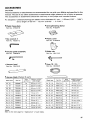
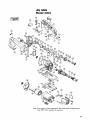
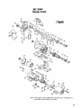
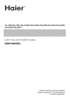
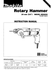
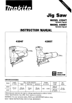
1
Jig Saw
MODEL 4304
Variable Speed
MODEL 4305
Variable Speed
INSTRUCTION MANUAL
4305
4304
DOUBLE
INSULATION
SPECIFICATIONS
Model
4304
4305
Length
of stroke
26"
(1")
Max. cutting capacities
Wood
Mild steel
135"
(5-5/16'7
10"
13/8")
Aluminum
(::,yg,,
Strokes
per minute
Overall
length
Net
weight
500 - 3,000
249 mm
(9-314")
285 mm
111-1/4")
2.3 kg
(5.1 lbs)
* Manufacturer reserves the right to change specifications without notice.
Note: Specifications may differ from country to country.
WARNING: For your personal safety, READ and UNDERSTAND before using.
SAVE THESE INSTRUCTIONS FOR FUTURE REFERENCE.
GENERAL SAFETY RULES
(For All Tools)
WARNING! Read and understand all instructions. Failure
to follow all instructions listed below, may result in electric
shock, fire and/or serious personal injury.
SAVE THESE INSTRUCTIONS
READ ALL INSTRUCTIONS.
1. Keep your work area clean and well lit. Cluttered benches and dark areas invite
accidents.
2. Do not operate power tools in explosive atmospheres, such as in the presence
of flammable liquids, gases, or dust. Power tools create sparks which may
ignite the dust or fumes.
3. Keep bystanders, children, and visitors away while operating a power tool.
Distractions can cause you to loose control.
4. Double Insulated tools are equipped w i t h a polarized plug (one blade is wider
than the other.) This plug will fit in a polarized outlet only one way. If the
plug does not fit fully in the outlet, reverse the plug. If it still does not fit,
contact a qualified electrician t o install a polarized outlet. Do not change
the plug in any way. Double insulation H eliminates the need for the three
wire grounded power cord and grounded power supply system.
5. Avoid body contact with grounded surfaces such as pipes, radiators, ranges
and refrigerators. There is an increased risk of electric shock if your body is
grounded.
6. Don't expose power tools t o rain or wet conditions. Water entering a power
tool will increase the risk of electric shock.
7. Do not abuse the cord. Never use the cord t o carry the tools or pull the plug
from an outlet. Keep cord away from heat, oil, sharp edges or moving parts.
Replace damaged cords immediately. Damaged cords increase the risk of
electric shock.
8. When operating a power tool outside, use an outdoor extension cord marked
"W-A' or "W." These cords are rated for outdoor use and reduce the risk
of electric shock.
9. Stay alert, watch what you are doing and use common sense when operating
a power tool. Do not use tool while tired or under the influence of drugs,
alcohol, or medication. A moment of inattention while operating power tools
may result in serious personal injury.
IO. Dress properly. Do not wear loose clothing or jewelry. Contain long hair. Keep
your hair, clothing, and gloves away from moving parts. Loose clothes, jewelry
or long hair can be caught in moving parts.
2
11. Avoid accidental starting. Be sure switch is off before plugging in. Carrying
tools with your finger on the switch or plugging in tools that have the switch
on invites accidents.
12. Remove adjusting keys or switches before turning the tool on. A wrench or
a key that is left attached t o a rotating part of the tool may result in personal
injury.
13. Do not overreach. Keep proper footing and balance at all times. Proper footing
and balance enables better control of the tool in unexpected situations.
14. Use safety equipment. Always wear eye protection. Dust mask, non-skid
safety shoes, hard hat, or hearing protection must be used for appropriate
conditions.
15. Use clamps or other practical way t o secure and support the workpiece t o
a stable platform. Holding the work by hand or against your body is unstable
and may lead t o loss of control.
16. Do not force tool. Use the correct tool for your application. The correct tool
will do the job better and safer at the rate for which it is designed.
17. Do not use tool if switch does not turn it on or off. Any tool that cannot
be controlled with the switch is dangerous and must be repaired.
18. Disconnect the plug from the power source before making any adjustments,
changing accessories, or storing the tool. Such preventive safety measures
reduce the risk of starting the tool accidentally.
19. Store idle tools out of reach of children and other untrained persons. Tools
are dangerous in the hands of untrained users.
20. Maintain tools with care. Keep cutting tools sharp and clean. Properly
maintained tools, with sharp cutting edges are less likely t o bind and are easier
t o control.
21. Check for misalignment or binding of moving parts, breakage of parts, and
any other condition that may affect the tools operation. If damaged, have
the tool service before using. Many accidents are caused by poorly maintained
tools.
22. Use only accessories that are recommended by the manufacturer for your
model. Accessories that may be suitable for one tool, may become hazardous
when used on another tool.
23. Tool service must be performed only by qualified repair personnel. Service
or maintenance performed by unqualified personnel could result in a risk of
injury.
24. When servicing a tool, use only identical replacement parts. Follow instructions in the Maintenance section of this manual. Use of unauthorized parts
or failure t o follow Maintenance Instructions may create a risk of electric shock
of injury.
3
ADDITIONAL SAFETY RULES
1. Avoid cutting nails. Inspect for and remove all nails from the workpiece before
operation.
2.Don't cut hollow pipe.
3.Do not cut oversize workpiece.
4. Check for the proper clearance beneath the workpiece before cutting so that
the blade will not strike the floor, workbench, etc.
5. Always wear eye protection conforming with current national standard.
Severe eye injury could result.
6. Hold the tool firmly.
7. Make sure cord is out of your way and not in the line of cut.
8. Make sure the blade is not contacting the workpiece before the switch is
turned on.
9. Keep hands away from moving parts.
IO. When cutting through walls,
floors or wherever "live" electrical wires may
be encountered, DO NOT TOUCH ANY METAL PARTS OF THE TOOL!
Hold the tool only by the insulated grasping surfaces t o prevent electric shock
if you cut through a "live" wire.
1 1 . Do not leave the tool running. Operate the tool only when hand-held.
12.Always switch off and wait for the blade t o come t o a complete stop before
removing the blade from the workpiece.
13.Do not touch the blade or the workpiece immediately after operation; they
may be extremely hot and could burn your skin.
4
The followings show the symbols used for tool.
v
.................................
A
.................................
Hz
kg
h
min
S
.................................
.................................
.................................
.................................
.................................
volts
amperes
herts
kilograms
hours
minutes
seconds
%
.................................
alternating current
- .................................
____
%
.................................
% .................................
.................................
direct current
no load speed
alternating or direct current
Class II Construction
A .................................
splash-proof construction
4 4 .................................
watertight construction
.../min ................................
cb .................................
revolutions or reciprocation per minute
number of blow
5
Installing or removing the saw blade
CAUTION:
Always be sure that the tool is switched off and unplugged before installing or removing
the blade.
To install the blade, loosen the screw on
With the blade teeth facing forward, insert
the blade into the blade holder as far as it
will go. Make sure that the back edge of
the blade fits properly in the groove of the
roller. Then firmly tighten the screw to
secure the blade.
1
P
-2
Jig saw balde
Roller
c
.Screw
CAUTION :
*Always secure the blade firmly. Insufficient securing of the blade may cause blade
breakage or serious injury.
Always clean out the blade holder before installing the blade. Chips or foreign matter on
the blade holder may cause insufficient securing of the blade.
*Use a lubricant or cutting oil between the blade and roller when cutting iron or composition board, etc. Failure to do so will shorten the service life of your blade and roller
or lead to potentially dangerous blade breakage.
6
Installing the universal shank jig saw blade
CAUTION :
Always be sure that the tool is switched off and unplugged before installing or removing
the blade.
If the universal blade clamp is used, you
can use blades of other makes which have
a universal shank like the one shown in
the figure, with a blade width of 6.35 mm
(1 /4" 1.
Insert the blade into the blade holder as far
as it will go. Make sure that the end of the
blade shank reaches the bottom of the
inner s l i t and tighten the bolt securely with
the hex wrench.
c-
The end of the blade
shank should reach the
bottom of the inner slit
Bolt
Selecting the cutting action
This tool can be operated with an orbital
or a straight line cutting action. To change
the cutting action, just turn the lever to the
desired cutting action position. Refer to
the table below to help determine the
appropriate cutting action.
7
Position
Cutting action
straightline
0
I
I
I11
I
Applications
For cutting mild steel, stainless steel and plastics.
cutting action
~~~
Smallorbit cutting action
Large orbit cutting action
1
For clean cuts in wood and plywood.
~~~~
~
~
~
~
I
~~~
For cutting mild steel, aluminum and hard wood.
For fast cutting in wood and plywood.
To start the tool, simply pull the trigger.
Release the trigger to stop. For continuous
operation, pull the trigger and move the
lock lever backward. To stop the tool from
the locked position, pull the trigger fully,
then release it.
w
Speed adjusting dial
I
Locklever
cSwitch
trigger
For 4305
CAUTION :
Before plugging in the tool, always check to see that the switch actuates properly.
To start the tool, slide the switch lever forward. Slide the switch lever backward to
stop.
8
,-Switch
lever
Speed adjusting dial
The tool speed can be adjusted and maintained between 500 and 3,000 strokes per
minute by turning the adjusting dial. The dial is marked 1 (lowest speed) to 6 (full speed).
:or 4304
-1
For 4305
Lock lever
Refer to the table a t right to select the
proper speed for the workpiece to be cut.
However, the appropriate speed may differ
with the type or thickness of the workpiece. In general, higher speeds will allow
you to cut workpieces faster but the
service life of the blade will be reduced.
-
Workpiece to be cut
Speed adjusting dial
Number on adjusting dial
Wood
5-6
Mild steel
3-6
Stainless steel
3-4
Aluminum
2-3
Plastics
1 - 4
CAUTION:
Adjust the speed adjusting dial only within the range of numbers 1 through 6. Do not
force the dial beyond this range or damage to the tool may result.
Cutting operation
CAUTION :
Check carefully that the blade i s adequately secured in position before plugging the tool
into electrical source.
Turn the tool on without the blade making any contact. Rest the base flat on the workpiece and gently move the tool forward along the previously marked cutting line.
I
For 4304
C u t t i n g line
I
I
gn i t tuC:
line
9
CAUTION :
Always hold the tool with the base flush with the workpiece. Failure to do so may cause
a slanted cutting surface and blade breakage.
*Advance the tool very slowly when cutting curves or scrolling. Forcing the tool may
cause a slanted cutting surface and blade breakage.
Bevel cutting
CAUTION :
Always unplug the tool before making any adjustments.
With the base tilted, you can make bevel
cuts a t any angle between 0" and 45' (left
or right). Loosen the bolt on the bottom of
the tool. Move the base so that the bolt is
positioned in the center of the cross-shaped
slot in the base.
Crossshaped slot
Tilt the base until the desired bevel angle i s
obtained. The edge of the motor housing
indicates the bevel angle by graduations.
Then tighten the bolt to secure the base.
/ /
Edge of motor housing
Graduations
Base
Flush cutting
Loosen the bolt on the bottom of the tool and slide the base all the way back. Then
tighten the bolt to secure the base.
For 4304
10
cutouts
Cutouts can be made with either of two methods A or B.
A) Boring a starting hole:
For internal cutouts without a lead-in cut from an edge, predrill starting hole more
than 12 mm (15/32") in diameter. Insert the blade into this hole and hold the tool
firmly against the workpiece to start your cut.
For 4304
/
p
/
A
Starting hole
Starting hole
B) Plung cutting
You need not bore a starting hole or make a lead-in cut if you carefully do as follows:
1. Tilt the tool up on the front edge of the base, with the blade point positioned just
above the workpiece surface.
2. Apply firm pressure to the tool so that the front edge of the base will not move
when you switch on the tool and gently lower the back end of the tool slowly.
3. As the blade slices into the workpiece, slowly lower the base of the tool down onto
the workpiece surface.
4. Complete the cut in the normal manner.
~
For 4304
For 4305
11
Finishing edges
To trim edges or make slight dimensional adjustments, run the blade lightly along the cut
edges.
'Of
I For 4305
Metal cutting
Always use a suitable coolant (cutting oil) when cutting metal. Failure to do so will cause
significant blade wear. The underside of the workpiece can be greased instead of using a
coolant.
Plastic base plate
Use the plastic base plate when cutting
decorative veneers, plastics, etc. It protects
sensitive or delicate surfaces from damage.
To replace the base plate, remove the four
screws with the hex wrench.
Anti-splintering device
To reduce the potential for workpiece surface splintering, the anti-splintering device
can be used. Fit it into the base from
below so that it surrounds the sides of the
blade.
ef
Base
Anti-splintering device
12
Guide rule (rip fence; optional accessory)
When cutting widths of under 150 mm
(5-29/32") repeatedly, use of the guide
rule will assure fast, clean, straight cuts. To
install it, loosen the bolt on the front of
the base. Slip in the guide rule and secure
the bolt.
Guiderule-
u
Circular guide (optional accessory)
Use of the circular guide insures clean,
smooth cutting of circles under 200 mm
(7-7/8") in radius. Insert the pin through
the center hole and secure it with the
threaded knob. Move the base of the tool
fully forward. Then install the circular
guide on the base in the same manner as
the guide rule (rip fence).
Pin
Vacuum head (optional accessory)
The vacuum head is recommended to perform clean cutting operations. Install the
plastic cover on the tool by fitting it into
the notches in the tool.
Fit into notches
Base
Plastic cover
13
To attach the vacuum head on the tool,
insert the hook of the vacuum head into
the hole in the base. Tighten the bolt to
secure the vacuum head. Then connect
a Makita vacuum cleaner to the vacuum
head.
Hex wrench
Plastic cover=\
I
-Hose
of vacuum cleaner
MAINTENANCE
CAUTION :
Always be sure that the tool i s switched off and unplugged before attempting to perform
inspection or maintenance.
To maintain product SAFETY and RELlABl LITY, repairs, carbon brush inspection and
replacement, any other maintenance or adjustment should be performed by Makita
Authorized or Factory Service Centers, always using Makita replacement parts.
14
ACCESSORIES
CAUTION:
These accessories or attachments are recommended for use with your Makita tool specified in this
manual. The use of any other accessories or attachments might present a risk of injury to persons.
The accessories or attachments should be used only in the proper and intended manner.
An exceotion: Universal shank .jig- saw blades with a thickness of 1 mm - 1.25 mm (1/32" - 3/64")
and a length of 58 mm - 8 2 mm (2-9/32" - 3-7/32").
Plastic base plate
Anti-splintering device
Part No. 415537-8
Part No. 41 5524-7
Plastic cover
*Hex wrench 3
Part No. 783201-2
Part No. 41 5525-5
Circular guide assembly
Guide rule
Part No. 123030.5
Part No. 1641 13-2
Hose 19 - 2.5
*Vacuum head
Part No. 192108-5
Part No. 192418-0
Jig saw blade (Packed 5 each)
I
Part No
I
Teeth
oer inch
I
Effective cutting
blade length
Blade type
NO.
6-18
6-19
I 792470-4 I
I 792471-2 I
14
NO.
80 mm 13-1/8")
NO
8-21
792472-0
12
75 mm (3")
No 8-22
792473-8
24
50 m m 12")
No. 6-10
792529-7
9
80 mm (3-1/8")
No. 8-12
792464-9
6
80 m m (3-1/8")
No. 6-24
No. 6-13
792465-7
8
80 mm I3-1/8''1
NO.
6-25
6-26
NO
No. 6-16
I
I
I
No. 6-17
I
No. 6-14
792468-1
I
1
I
792469-9
I
792466-5
792467-3
6-23
50 m m 12"l
NO.
50 m m 12")
No. 8-27
6
I
I
I
80 m m 13-1/8"1
No. BR-13
6
I
70 m m 12-3/4"1
18
12
Effective cutting
blade length
Teeth
per inch
80 mm 13-1/8")
No. 51
No. 6-15
Part No.
12
792474-6
14
I 792475-4 I
32
I 792476-2 1
I 792477-0 I
I 792478-8 I
24
792727-3
9
9
9
I
I
45 mm (1-3/4")
65 mm (2-1/2"1
50 mm I2"J
1
I
I
I
50"
12")
75 mm (3'7
70 m m (2-3147
50"
12"l
64 m m 12-1/2"1
(Note)
Refer to the next page for "Application" of each blade.
15
Jig saw blade
Blade type
Application
'
Wood and plywood
Plastics
Aluminum
-
1.5 - 3 mm thick
11/16" - 118")
H
1 - 6 mm thick
13/64' - 1 / 4 ' l
No. 51
NO. 58
I
4 - 60 mm thick
15/32" - 2-3/6"1
4 - 6 0 mm thick
15/32" - 2-318")
I
s
4 - 3 0 mm thick
15/32" - 1-116")
4 - 3 0 mm thick
15/32" - 1-1/8")
No. 59
I
Mild steel
I
Feature
-
For fast cutting.
-
For fast finish work.
S
-
3 - 60 mm thick
11/E" - 2 - 3 / 6 7
- 60 mm thick
1118" - 2-316'7
3
No. 6 - 1 0
S
3 - 50 mm thick
1118" - 2")
3 - 3 0 mm thick
1118' - 1-118")
No. 6-11
I
-
s
For fast finish work,
especially in plywood
For fast finish work.
For fast finish work.
I
-
For roughing-in work.
Ideal for cutting
thin materials.
3 - 30 mm thlck
11/8' - 1-1/6")
No. 6 - 1 5
3 - 3 0 mm thick
11/8' - 1-1/6")
H
I
5 - 60 mm thick
113164" - 2.318'7
No. 6 - 1 6
5 - 60 mm thick
113/64" - 2-3/8")
I -
thin materials.
I
-
-
S
No.6-17
I
I
2 - 3 0 mm thick
15/64" - 1-118")
2 - 3 0 mm thick
15/64" - 1-1/8'7
No. 6 - 1 8
For fast cutting
-
Ideal for scroll cutting.
-
Ideal for scroll cutting.
S
No. 6 - 1 9
3 - 3 0 mm thick
1118'' - 1-1/8")
No. 6-21
-
3 - 3 0 mm thick
1118" - 1-1/8')
H
Cuts on down stroke.
Splinter-free on finish side.
3 - 55 mm thick
1118' - Z - l / E ' I
3 - 10 mm thick
1118" - 318")
For finish work,
especially in plastics
H
No. 6-22
-
1.5 - 3 mm thick
11/16' - 1/6"1
H
1 - 6 mm thick
13/64" - 1 / 4 ' l
No. 8-23
-
3 - 6 mm thick
11/8" - 114")
H
3 - 10 mm thick
11/8" - 318")
No. 6-24
I
I
-
I
I
U
I
3 - 55 mm thick
(1/8" - 2-1/8')
H
No. 6-27
No. 13-13
No.
~
~
.
5 - 110 mm thick
113/64" - 4-5/16"]
NOTE:
"H" stands for hard materials
"S" stands for soft materials
16
'w"
I
Also ideal for cutting
stainless steel.
~ , ~ ~ , ? - m Also
~ l ideal
~ ~for! cutting
~
stainless steel.
3 - 3 0 mm thick
1118" - 1-118'7
3 - 55 mm thick
11/8' - 2-118")
U
0.5 - 3 mm thick
11/64' - 118")
thick
-
I
3 - 55 mm thick
11/8' - 2-1/8')
No. 6-25
No. 6-26
; I
1- 3
thick
13/64" - 116")
I
'"8'
~
I
3 - 55 mm thick
11/E" - 2-1/8")
H
3 - 3 0 mm thick
11/8" - 1-118")
1.5 - 3 mm thick
11116" - 118")
1 - 6 mm thick
13/64" - 114")
~
k
l
5 - 110 mm thick
113164" - 4-5/16"]
13164" - 118'7
- 3" thick
I
ldaal for scroll cutting.
requiring no sanding.
JIG SAW
Model 4304
Note: The switch, noise suppressor and other part configurations
may differ from country to country.
17
MACHINE
MACHINE
~
1
2
3
4
5
29
30
31
32
33
34
35
36
1
1
1
1
1
1
2
1
1
1
1
1
1
2
2
1
1
1
2
1
1
1
1
1
1
1
1
1
1
1
1
1
1
1
1
37
38
39
40
1
1
3
1
6
7
9
10
11
12
13
14
15
16
17
18
19
20
21
22
23
24
25
26
27
28
Switch
Handle Set IWith Item 551
Tapping Screw Flange PT 4x20
Cord
Cord Guard
Strain Relief
Tapping screw 4 x i a
PI" 3
Switch Lever
Spacer
Compression Spring 4
Lock On Lever
Controller
Tapping Screw Flange PT 4x20
Tapping Screw CT 4x16
Gear Housing Cover Complete
Holder
Slider
Countersunk Head Screw M4x10
Thrust Plate
Needle Bearing 607
Crank Complete
Flat Washer 26
Balance Plate
Balance Plate
Push Plate
Flat Washer 26
Needle Bearing 8 1 0
Helical Gear 51
Needle Bearing 810
Flat Washer 8
Gear Shaft
Ball Bearing 607LLB
Insulation WaIher
ARMATURE ASSEMBLY
[With Item 34 35 37 E 381
Fan 54
EW B e m g 6 0 8 ~ ~ 8
Pan Head Screw M4x10 [With Washed
Flat Washer 6
Note The switch and other part spec!fIcalions may differ tram Country
18
41
42
43
44
45
46
47
48
49
50
51
52
53
54
55
56
57
58
59
60
61
62
63
64
65
66
67
68
69
70
71
72
73
74
75
76
77
78
79
80
10
1
1
1
1
2
1
1
2
2
1
1
2
1
1
1
1
1
t
1
1
1
1
1
1
1
1
1
1
1
4
1
2
2
1
1
2
1
1
2
1
country
Flat Washer 5
Stop Ring E-4
Flat Washer 6
Gear Housmg Complete [With Item 631
Tapping Screw Flange PT 4x20
Packing
Retaining Ring S-8
Pan Head Screw M4x16 IWith Washer)
Compression Spring 4
Stop Ring E-3
Pin 4
Tapping Screw Bind MT 4x55
Retainer Complete
Tapping Screw Flange PT 4x35
Handle Set [With Item 21
Rod
Hex Socket Head Bolt M6x8
Slide Plate
Lever 17
Compression Spring 4
Steel Ball 4
Stop Ring E - 5
Rubber Pin 4
Base
Clamp Plate
Hex Socket Head Bolt M4x25
Bare Plate
Baffle piate
Fteld
Hex Socket Head 8011 M5x8
Motor Housing
Carbon Brush
Brush Holder
Name Plate
Rear Cover
Tapping Screw Flange PT 4x30
Makita Label
cap
Tapping Screw Flange PT 4x60
Rubber Ring 19
JIG SAW
Model 4305
Note: The switch, noise suppressor and other part configurations
may differ from country to country.
19
MAKlTA LIMrrEDONE YEAR WARRANTY
I
Warranty Policy
Every Makita tool is thorou ly inspezted and tested before leaving the factory. It is warranted to
be free of defects from w o r & k p and materials for the period of ONE YEAR from the date of
original purchrsc. Should any trouble develop during this oneyear period, return the COMPLETE
t d , freight prepaid, to one of Makita's Factory 01 Authorized Service Centers. If inspeetion show
the trouble is caused by defective workmanship or m a t e d . Makita will repair (or at our option,
replace) without chap.
This W m t y does not apply where:
repain have been made or attempted by othcn:
0
vain are required &cause of normal wear and tear:
The tool hrr bccn abuscd, miawed or impropcdy maintained;
alterations have bccn made to the tool.
IN NO EVENT SHALL MAKITA BE LIABLE FOR ANY INDIRECT,INCIDENTAL OR CONSEQUENTIAL DAMAGES FROM THE SALE OR USE O F THE PRODUCT. THIS DISCLAIMER
APPLIES BOTH DURING AND AFTER THE TERM O F THIS WARRANTY.
MAKITA DISCLAIMS LIABILITY FOR ANY IMPLIED WARRANTIES, INCLUDING IMPLIED
WARRANTIES O F "MERCHANTABILKY AND "FITNESS FOR A SPECIFIC PURPOSE,"
AFTER THE ONEYEAR TERM O F THIS WARRANTY.
This W m t y givca you ipsifg le@ Wts. and you may ala0 have other rights which v u y from
rtatc to ttate. Some rtatca do not aUow the exclusion 01 h i l a t i o n of incidental or cohuqucnti.l
dun(0 the above limitation or cxdurion may not apply to you. Same states do not aUow
limitation on how long an implied wurnnty b t h (0 the .bow h i t a t i o n may not apply to you.
MAKITA MANUFACTURING EUROPE LTD
ROAD 7, HORTONWOOD INDUSTRIAL ESTATE
TELFORD, SHROPSHIRE TF1 4GP ENGLAND
Part No. 883923-067
I