1
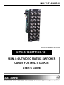
MULTI-TASKER™
MANUAL PART NUMBER: 400-0131-004
MT105-100/MT105-101
16-IN, 8-OUT VIDEO MATRIX SWITCHER
CARDS FOR MULTI-TASKER
USER’S GUIDE
MULTI-TASKER™
TABLE OF CONTENTS
Page
PRECAUTIONS / SAFETY WARNINGS .............. 2
GENERAL..........................................................2
INSTALLATION .................................................2
CLEANING.........................................................2
FCC / CE NOTICE..............................................2
ABOUT YOUR MT105-100/101 ............................ 3
TECHNICAL SPECIFICATIONS .......................... 3
DESCRIPTION OF MT105-100/101 ..................... 4
APPLICATION DIAGRAMS................................... 5
DIAGRAM 1: TYPICAL SETUP ..........................5
DIAGRAM 2: INTERNAL VIEW MT105-100 .......6
DIAGRAM 3: INTERNAL VIEW MT105-101 .......7
INSTALLING YOUR MT105-100/101 ................... 8
OPERATION .......................................................... 8
RS-232 CONTROL.............................................8
DESCRIPTION OF COMMANDS .......................8
SUMMARY OF COMMANDS. ..........................18
MENU MODE ...................................................18
TROUBLESHOOTING GUIDE ............................ 22
NO DISPLAY....................................................22
ALTINEX POLICY................................................ 22
LIMITED WARRANTY/RETURN POLICY ........22
CONTACT INFORMATION ..............................22
400-0131-004
1
1
MULTI-TASKER™
PRECAUTIONS / SAFETY WARNINGS
1.4 FCC / CE NOTICE
1
•
Please read this manual carefully before using your
MT105-100/101. Keep this manual handy for future
reference. These safety instructions are to ensure
the long life of your MT105-100/101 and to prevent
fire and shock hazard. Please read them carefully
and heed all warnings.
1.1 GENERAL
•
•
Qualified ALTINEX service personnel, or
their authorized representatives, must
perform all service.
1.2 INSTALLATION
•
•
•
To prevent fire or shock, do not expose this
unit to rain or moisture. Do not place the
MT105-100/101 in direct sunlight, near
heaters or heat radiating appliances, or near
any liquid. Exposure to direct sunlight,
smoke, or steam can harm internal
components.
Handle the MT105-100/101 carefully.
Dropping or jarring can damage the card.
Do not pull the cables that are attached to
the MT105-100/101.
•
•
Insert the card carefully into the slots of the
Multi-Tasker™ without bending any edges.
• When removing a card, please make sure
that the card to which it is attached is also
pulled out simultaneously to prevent damage
to the cable and connectors.
1.3 CLEANING
•
Clean only the connector area with a dry
cloth. Never use strong detergents or
solvents, such as alcohol or thinner. Do not
use a wet cloth or water to clean the card.
Do not clean or touch any component or
PCB.
400-0131-004
2
2
This device complies with part 15 of the FCC
Rules. Operation is subject to the following
two conditions: (1) This device may not
cause harmful interference, and (2) this
device must accept any interference
received, including interference that may
cause undesired operation.
This equipment has been tested and found
to comply with the limits for a Class A digital
device, pursuant to Part 15 of the FCC
Rules. These limits are designed to provide
reasonable protection against harmful
interference when the equipment is operated
in a commercial environment. This
equipment generates, uses, and can radiate
radio frequency energy and, if not installed
and used in accordance with the instruction
manual, may cause harmful interference to
radio communications. Operation of this
equipment in a residential area is likely to
cause harmful interference in which case the
user will be required to correct the
interference at their expense.
Any changes or modifications to the unit not
expressly approved by ALTINEX, Inc. could
void the user’s authority to operate the
equipment.
MULTI-TASKER™
ABOUT YOUR MT105-100/101
2
TECHNICAL SPECIFICATIONS
MT105-100/MT105-101
16-in 8-out Video Matrix Switcher Cards
FEATURES/
DESCRIPTION
GENERAL
Inputs
External Input Connectors
Internal Input Connectors
Outputs
Output Connector
Compatibility
Using 1 Card
The MT105-100/101 16-in, 8-out Video Matrix
Switcher card is designed to allow the routing of
computer and broadcast video in audio/visual
presentation systems. This card enables 16
composite video sources to be connected and
switched to eight different display or recording
devices. Inputs are selected via easy-to-use ASCII
commands from a control system or computer
connected to the RS-232 port of a Multi-Tasker™
enclosure.
Using 2 Cards
Using 3 Cards
Using 4 Cards
Using 5 Cards
Multiple MT105-100/101 cards can be installed in
the enclosure to provide additional functionality. For
example, two cards can be used to handle the two
components of an S-Video signal (Chroma and
Luma), three cards to handle Component Video,
and five cards to handle RGBHV. When using
these cards to switch RGBHV format signals, it is
possible to adapt the 5 BNC connectors to a VGAtype, 15-pin HD connector using ALTINEX adapter
cables, such as part # MS8102CA.
MT105-100/101
16
16 BNC female
10-pin IDC
8
8 BNC female
Composite Video
(NTSC, PAL, SECAM)
S-Video
Component Video
RGBS
RGBHV
Table 1. MT105-100/101 General
MECHANICAL
Enclosure Slots Required
Weight
Connector Panel
T° Operating
T° Maximum
Humidity
MTBF (calc.)
The MT105-100 uses solid state switching
technology and offers a video bandwidth of
350MHz, enabling it to pass high-resolution video
signals without degradation.
MT105-100/101
3
1.0 lb (0.45 kg)
Black
10°C-35°C
50°C
90% non-condensing
40,000 hrs
Table 2. MT105-100/101 Mechanical
ELECTRICAL
MT105-100/101
Input Signals
Impedance
75 ohms
Analog
1.5Vp-p max.
Output Signals
Impedance
75 ohms
Gain
1.05
Frequency Compatibility
Bandwidth
MT105-100
350 MHz @ -3dB
MT105-101
200 MHz @ -3dB
Power
Power from
Power
+6V
-6V
MT100-100
Consumption
MT105-100
450mA
380mA
5.0 watts
MT105-101
200mA
150mA
2.1 watts
The
MT105-101
provides
an
economical
application that does not involve the use of
extremely high-resolution computer video signals.
This card is designed for 200MHz bandwidth
performance.
Table 3. MT105-100/101 Electrical
400-0131-004
3
3
3
MULTI-TASKER™
DESCRIPTION OF MT105-100/101
4
TOP RETAINER SCREWS
16 VIDEO
INPUTS
8 VIDEO
OUTPUTS
BOTTOM RETAINER SCREWS
400-0131-004
4
4
MULTI-TASKER™
APPLICATION DIAGRAMS
5
DIAGRAM 1: TYPICAL SETUP
MT105-100
400-0131-004
5
5
MULTI-TASKER™
DIAGRAM 2: INTERNAL VIEW MT105-100
16X8 MATRIX SW + 300MHZ + BNC IN/OUT
BNC
BNC
IN 1
GLI
IN 2
GLI
IN 3
GLI
IN 4
GLI
IN 5
GLI
IN 6
GLI
IN 7
GLI
IN 8
GLI
IN 9
GLI
IN 10
GLI
IN 11
GLI
IN 12
GLI
IN 13
GLI
IN 14
GLI
IN 15
GLI
IN 16
GLI
OUT 1
OUT 2
OUT 3
MATRIX
SWITCHER
OUT 5
OUT 6
OUT 7
OUT 8
MATRIX
CONTROL
400-0131-004
OUT 4
6
6
MULTI-TASKER™
DIAGRAM 3: INTERNAL VIEW MT105-101
16X8 MATRIX SW + 200MHZ + BNC IN/OUT
BNC
BNC
IN 1
IN 2
OUT 1
IN 3
IN 4
OUT 2
IN 5
IN 6
OUT 3
IN 7
IN 8
MATRIX
SWITCHER
IN 9
IN 10
OUT 4
OUT 5
IN 11
IN 12
OUT 6
IN 13
IN 14
OUT 7
IN 15
IN 16
OUT 8
MATRIX
CONTROL
400-0131-004
7
7
MULTI-TASKER™
INSTALLING YOUR MT105-100/101
The cards in a Multi-Tasker™ system are
capable of performing various functions, as well
as providing feedback to the user or control
system. Commands instruct a card to perform
specific actions or request information about the
status of the card. Some commands do both at
the same time.
6
Step 1. Turn off power to the Multi-Tasker™
enclosure.
Step 2. Slide the MT105-100/101 into an available
slot in the Multi-Tasker™ enclosure in
order to connect to the bus. Make sure
that the MT105-100/101 card fits into
place. Secure the card to the
Multi-Tasker™ by tightening the retainer
screws located on the top and bottom of
the MT105-100/101 card.
A command that instructs the card to simply
perform an action will generate feedback of “[ ]”.
The open and close brackets indicate the card
received a valid command. If the command
requested information from the card, the
feedback generated by the card is the
acknowledgement of having received a valid
command.
Invalid
commands
generate
feedback of “[ERR001]”.
Step 3. Turn on power to the Multi-Tasker™
enclosure.
Step 4. Connect a coaxial cable from the video
source to the input connector of the
MT105-100/101. Connect the output
connectors of the MT105-100/101 to the
display devices through a coaxial cable.
After processing a command, an “OK” or
[ERR001] will be returned as feedback if “F” is
included at the end of a command string.
Commands ending in “S” will be saved into
memory. Commands not ending in “S” will still
be executed but will not be restored when the
system is reset or powered off then on.
Step 5. Starting from the left, identify the slot
number where the MT105-100/101 card is
plugged into the Enclosure and note that
it is for RS-232 control.
OPERATION
7.2 DESCRIPTION OF COMMANDS
7
Each command consists of three
Function, Card ID, and Unit ID.
[ Function , Card ID , Unit ID ]
7.1 RS-232 CONTROL
The MT105-100/101 has many advanced remote
control capabilities, which are accessible through
standard RS-232 communication. Actual control
may be accomplished through a computer control
system or any other device capable of sending
RS-232 commands.
Example: [VERC3U2]
VER = Function
C3 = Card ID or Group ID
U2 = Unit ID
7.1.1 RS-232 INTERFACE
For Function, see a detailed explanation under
each command description.
The RS-232 commands, for the MT105-100/101
are in a simple ASCII character format.
1.
Square brackets “[
command.
2.
Use uppercase letters for all commands.
parts:
The Card ID is a unique identifier. It is equal to
the enclosure slot number, or it may be an
assigned value. As the slot number, the value
can range from 1 to 4 up to 1 to 20 depending
on the enclosure. If the value is assigned, the ID
may be a maximum of 99.
]” are part of the
Card ID 0 (C0) is used for the controller and
cannot be reassigned.
400-0131-004
8
8
MULTI-TASKER™
The Group ID is a number representing a group
of cards defined with the [WR] command. When
using the Group ID, all cards in the group will
perform the given instruction.
Example:
An MT105-100/101 card is in slot 2, Input 1 is
connected to all outputs and outputs 1, 2 and 3
are on. Send the command [C2] and receive the
following feedback:
Changing the position of a card will significantly
affect the commands recorded on software
definitions or third party control systems.
Matrix:16X8
In01-Out1 ON
In01-Out2 ON
In01-Out3 ON
In01-Out4 OFF
In01-Out5 OFF
In01-Out6 OFF
In01-Out7 OFF
In01-Out8 OFF
The Unit ID has a value from 0 to 9. Unit ID 0
should be used for single unit operation. If the
Unit ID is set to zero, each command may be
used without Ui. Use the command [SETU0],
as explained in the MT100-100 User’s Guide.
Example:
[VERC3]:
For Unit ID Zero
[VERC3Ui]: For Unit ID other than Zero
[VERC3]:
Equivalent to [VERC3U0]
NOTE: If there is no card in slot 2, sending the
command [C2] will not return any feedback.
3. [CnS]
1. [VER]
Command Format: [VERCnUi]
This command saves the input to output
settings as well as the output enable status.
This configuration will be restored after the
system is reset or powered off then on.
Cn = Card ID (n = slot # from 1 to max slots)
Command Format: [CnSUi]
Ui = Unit ID (i = # from 0 to 9)
Cn = Card ID (n = # from 1 to max slots)
Example:
S
There is an MT105-100 in slot 4. Send the
command [VERC4] and receive the following
feedback:
Ui = Unit ID (i = # from 0 to 9)
This command displays the software version
and model for the MT105-100/101 card.
Example:
Input 1 is connected to all 8 outputs, but only 1
through 4 are on. Send the command [C4S] for
slot 4, and receive the following feedback:
[MT105-100 690-0126-014 C04]
MT105-100
= Card Model Number
690-0126-016 = Software Version
C04
= Card ID
Matrix:16X8
In01-Out1 ON
In01-Out2 ON
In01-Out3 ON
In01-Out4 ON
In01-Out5 OFF
In01-Out6 OFF
In01-Out7 OFF
In01-Out8 OFF
2. [C]
This command displays the status of the card
and connections of the matrix switcher.
Command Format: [CnUi]
Cn = Card ID (n = # from 1 to max slots)
Ui = Unit ID (i = # from 0 to 9)
400-0131-004
= save configuration
[SAVEDC04]
9
9
MULTI-TASKER™
FEEDBACK COMMANDS: ?, ?Cn and STA
Example:
The next three commands are a function of both
the card and the front panel and are only
available with Multi-Tasker™ Front Panel
systems that have the following firmware:
The MT105-100 in slot 4 has Input 1 connected
to all outputs. Outputs 1-4 are on and the
remainder off. Send the command [?C4] to
receive feedback status similar to the following.
690-0122-015
690-0123-004
690-0124-018
[(MT105-100C04)(VR690-0126-014C04)
(ON11110000C04)(MA0101010101010101C04)]
= Version 015 or later.
= Version 004 or later.
= Version 018 or later.
All status feedback is enclosed in brackets, “[ ]”.
Each data field within the status is enclosed in
parentheses. The first two characters identify
the status type. The last three characters are
the card’s ID.
NOTE: In MTSetup™, send the command
[VER] from the terminal window. The system will
respond with feedback that includes the
following:
MT105-100
VR690-0126-014
ON11110000
MA0101010101010101
690-0122-015 690-0123-004 690-0124-018
Check the last three digits against the numbers
above to determine if the option is available.
4. [?]
The on/off status line is read from left to right as
outputs one through eight. A “1” indicates the
output is on and a “0” indicates the output is off.
This command will return general information
about the Multi-Tasker™ and cards installed in
the unit.
The I/O connections are also read left to right
representing outputs one through eight and the
input to which each is connected. The first two
digits show the input number to which Output 1
is connected. In this case, Output 1 is
connected to Input 1. The next two numbers
indicate Input 1 is connected to Output 2 and so
on.
Command Format: [?Ui]
Ui = Unit ID (i = from 0 to 9)
Example:
A Multi-Tasker™ with Unit ID 1 has a front panel
with part number MT101-101 and contains an
MT103-122, MT103-123 and MT105-100. Send
the command [?U1] and receive the following
feedback:
6. [STA1]
This command enables automatic feedback
from the front panel. The command affects any
card with auto-feedback capability, not just the
MT105-100/101. The default at power on or
reset is STA0, off. For more details, see the
[?Cn] command definition.
[(MT101-101U1)(MT103-122C01)
(MT103-123C02)(MT105-100C05)]
MT101-101U1 = Panel Number and Unit ID
MT103-122C01 = An MT103-122 is in slot 1
MT103-123C02 = An MT103-123 is in slot 2
MT105-100C05 = An MT105-100 is in slot 5
Command Format [STA1] = On
5. [?C]
Feedback Prefix Definitions:
ON
Output on/off status
MA
Matrix settings
This command will return general information
about the card and its status.
Command Format: [?CnUi]
Cn = Card ID (n = # from 1 to max slots)
Ui = Unit ID (i = from 0 to 9)
400-0131-004
= Card Model Number
= Firmware version
= Output on/off status
= I/O connections
10
10
MULTI-TASKER™
Example:
Command Format: [ONmGkUi]
Command = [I2O*C4]
Feedback = (MA0202020202020202C04)
MA
= Matrix Settings
0202…02 = Output connections
C04
= Card ID
m
Gk = Group number (k = # from 1-8)
Ui = Unit ID (i = # from 0-9)
Example:
[ON1G1]: Turns on Output 1 for each card in
Group 1. See the GROUP commands for a
detailed explanation.
Output Connection Description:
Reading from left to right, the first two digits are
for output 1, the next two for output 2, and so
on. Each two digit pair represents the input
number to which each output is connected.
PATH OPERATION
This command will set the path for the output,
but it is not active until the switch command,
[SW], is executed. Commands ending in “P” are
not executed immediately. The path for outputs
on multiple cards, or the same card, may be
preloaded.
7. [STA0]
This command disables automatic
from the card and front panel. The
affects any card with auto-feedback
not just the MT105-100/101. The
power on or reset is STA0, off.
= Output number (m = # from 1-8)
feedback
command
capability,
default at
Command Format: [ONmCnUiP]
m
Command Format [STA0]
= Output number (m = # from 1 to 8)
Cn = Card ID (n = slot # from 1 to max slots)
8. [ON]
This command will enable one or more outputs
for a single card, or a group of cards.
Ui = Unit ID (i = # from 0 to 9)
SINGLE CARD OPERATION
Example:
Command Format: [ONmCnUi]
Cn = Card ID (n = # from 1 to max slots)
There are two MT105-100 cards in slots 6 and
9. Enable Output 1 of card 6 and Output 3 of
card 9 simultaneously. To do this, send the
following commands:
Ui = Unit ID (i = # from 0 to 9)
[ON1C6P] , [ON3C9P] and [SW]
Example:
If “F” is included, use the [ONmCnPF] command
or the [ONmCnFP] command.
m
P
= Output number (m = # from 1 to 8)
There is an MT105-100 card in slot 5. All of the
outputs are off.
= Path
FEEDBACK OPERATION
1)
[ON1C5]:
Turns on only Input 1.
Command Format: [ON…..F]
2)
[ON3C5]:
Turns on only Input 3. Inputs 1
and 3 are now on.
After processing a command, an “OK” or
“[ERR001]” will be returned as feedback if “F” is
included at the end of a command string.
GROUP OPERATION
Example:
This command enables output “m” for each card
in group “k” of unit “i”.
400-0131-004
[ON1C2F]: if path is not set
[ON1C2PF]: if path is set
11
11
MULTI-TASKER™
Command Format: [OFFmCnUiP]
9. [OFF]
This command disables one or all outputs of a
single card or a group of cards.
m
SINGLE CARD OPERATION
Ui = Unit ID (i = # from 0 to 9)
Command Format: [OFFmCnUi]
P
m
Example:
Cn = Card ID (n = # from 1 to max slots)
= Output number (m = # from 1 to 8)
Cn = Card ID (n = # from 1 to max slots)
Example:
Card 5 has Output 1 on.
The following
commands may be used to turn off the output.
[OFF1C5]:
[OFFC5]:
= Path
There are two MT105-100 cards in slots 6 and
9. Disable Output 1 of card 6 and Output 3 of
card 9 simultaneously using the following
commands:
Ui = Unit ID (i = # from 0 to 9)
1)
2)
= Output (m = # from 1 to 8)
[OFF1C6P] , [OFF3C9P] and [SW]
If “F” is included, use the [OFFmCnPF]
command or the [OFFmCnFP] command.
Turns off only Output 1.
Turns off all outputs.
FEEDBACK OPERATION
GROUP OPERATION
This command disables output “m” for each
card in group “k” of unit “i”.
After processing a command, an “OK” or
“[ERR001]” will be returned as feedback if “F” is
included at the end of a command string.
Command Format: [OFFmGkUi]
Command Format: [OFF…..F]
m
Example:
= Card Output (m = # from 1-8)
Gk = Group ID (k = # from 1-8)
[OFF1C2F]: if path is not set
Ui = Unit ID (i = # from 0-9)
[OFF1C2PF]: if path is set
Example:
1.
2.
10. […S] – SAVE
[OFF1G1]: Turns off Output 1 for each card
in group 1.
[OFFG1]: Turns off all outputs for each
card in group 1.
This command will save the configuration
command being sent in memory.
When
sending the command [I1O1C4S], after reset or
power up, Input 1 will be connected to Output 1
on C4. This command only saves the Input 1 to
Output 1 connection above. In order to save all
the current settings, use the [CnS] command.
PATH OPERATION
This command will set the path for the output,
but it is not active until the switch command,
[SW], is executed. Commands ending in “P” are
not executed immediately. The path for outputs
on multiple cards or the same card may be
preloaded.
400-0131-004
11. […F] – FEEDBACK
After processing a command, an “OK” or
“[ERR001]” will be returned as feedback if "F" is
included at the end of a command string.
12
12
MULTI-TASKER™
Example:
12. […P] – PATH
The following commands set the path for turning
on Output 1 of the card in slot 6 and turning off
Output 3 of the card in slot 9. Nothing happens
until the [SW] command is sent. At that time,
Output 1 will be enabled and Output 3 will be
disabled.
This command will set the path for the output,
but it is not active until the switch command,
[SW], is executed. Commands ending in "P" are
not executed immediately. The path for outputs
on multiple cards or the same card can be
preloaded. See the examples in [ON] and [OFF]
commands.
[ON1C6P] , [OFF3C9P] and [SW]
Example:
14. [ImOx]
There is an MT105-100 in slot 4. Currently,
Input 1 is connected to all outputs and all
outputs are on. The path command has been
used to set Input 2 to Output 1 and turn off
Outputs 2 and 3 at the same time. If checking
the status prior to sending the [SW] command,
the feedback will appear as follows for the
above connection settings:
This command connects a single input to a
single output in the current matrix configuration.
Command Format: [ImOxCnUi]
m
x
Cn
Ui
In01-Out1 ON P=2
In01-Out2 ON P=OFF
In01-Out3 ON P=OFF
In01-Out4 ON
In01-Out5 ON
In01-Out6 ON
In01-Out7 ON
= Input (m= # from 1 to 16)
= Output (x = # from 1 to 8)
= Card ID (n = slot # from 1 to max slots)
= Unit ID (i = # from 0 to 9)
Example:
Connect Input 1 to Output 1 for the MT105-100
in slot 5. Send the command [I1O1C5] and
Input 1 will be connected to Output 1.
15. [ImO*]
This command connects a single input to all the
outputs in the current matrix configuration.
The notation "P=" at the end of the line indicates
the path condition is active. "P=2" on the
Output 1 line indicates that after the [SW]
command, Input 2 will be connected to
Output 1.
Command Format: [ImO*CnUi]
m = Input (m = # from 1 to 16)
Cn = Card ID (n = slot # from 1 to max slots)
Ui = Unit ID (i = # from 0 to 9)
The notation "P=OFF" on lines 2 and 3 indicates
that Outputs 2 and 3 will be turned off after the
[SW] command is executed.
Example:
Connect Input 1 to all outputs for the
MT105-100 in slot 5. Send the command
[I1O*C5] and Input 1 will be connected to all
outputs.
13. [SW] – SWITCH
This command immediately connects inputs and
outputs previously set with the path command.
The command switches all paths set on this
card and all other cards in the enclosure.
16. [CLR]
This command performs a reset of the card and
restores settings to the factory defaults.
Command Format: [CLRCnUi]
Cn = Card ID (n = # from 1 to max slots)
Ui = Unit ID (i = # from 0 to 9)
400-0131-004
13
13
MULTI-TASKER™
Example:
ID COMMANDS: RSI, SIDn, SIDnCi, SID+, RSN
The default Card ID is the same as the card slot
number. The next several commands allow the
user to change the Card ID to a value other than
the slot number. Once the ID is changed,
moving the card to another slot will not change
the card ID. If a card in slot 4 is set to ID 1, then
moved to slot 10, its ID will remain 1. The RSI
command forces the installed cards to take their
slot number as their ID number, regardless of
the slot in which they are installed.
Send the command [CLRC4] to reset the card in
slot 4. After the reset, the status of C4 will be
similar to the following depending on the matrix
configuration:
Matrix:16X8
In01-Out1 ON
In01-Out2 ON
In01-Out3 ON
In01-Out4 ON
In01-Out5 ON
In01-Out6 ON
In01-Out7 ON
In01-Out8 ON
Some cards require more than one slot in the
Multi-Tasker™ system. As an example, some
matrix switcher cards require 4 slots. If there are
5 of these cards installed, they would be
numbered C4, C8, C12, C16 and C20.
Changing the Card ID allows the user to define
the cards as C1, C2, C3, C4 and C5.
Input 1 will be connected to all outputs and all
outputs will be enabled.
Another use for changing the Card ID is to be
able to use multiple systems without having to
set each unit to a different Unit ID. All systems
may be left as Unit ID 0 for ease of
programming. The cards in the first unit may be
numbered 1-10 and in the second unit 11-20.
17. [FBD]
This command turns feedback delay on or off. It
is necessary when installing some newer cards
in older systems. If the system does not receive
all of the feedback from the card, the card may
be communicating too fast. This command will
slow down the card's communication rate.
The ID commands work with all Multi-Tasker™
Front Panel systems. However, front panels that
have firmware releases prior to the following will
not be able to address Card ID's greater than
the number of slots in the system:
Command Format: [FBDmCnUi]
m
= Delay (0= no delay, 1= delay 100mS)
Cn = Card ID (n = # from 1 to max slots)
690-0122-019 = Version 019 or later.
Ui = Unit ID (i = from 0 to 9)
690-0123-005 = Version 005 or later.
Example:
690-0124-019 = Version 019 or later.
The command [HELPC4] is sent to the card in
slot 4. Some of the HELP file is displayed on the
screen, but most is missing. Send the command
[FBD1C4] to slow down the rate at which the
card sends feedback to the system.
NOTE: Send the command [VER] to the
Multi-Tasker™. The system will respond with
feedback which includes:
690-0122-019 690-0123-005 690-0124-019
Check the last three digits against the numbers
above to determine if the Card ID commands
can address all 99 Card ID's.
400-0131-004
14
14
MULTI-TASKER™
18. [RSI]
21. [SID+n]
This command resets the card ID's in the
system. After sending this command, each card
ID in the system will match the slot number of
the card. If the card is moved to another slot, its
ID number will be the new slot number.
This command sets the ID of all the cards in a
system to their slot number plus an offset value.
Command Format: [SID+n]
n = Offset amount (n = # from 0 to 98)
The maximum ID is 99, so subtract the
highest slot number from 99 to find the
maximum offset. For example, in an 8
slot enclosure, the maximum offset would
be 91. The slot number, 8, plus the offset,
91, equal 99.
Command Format: [RSI]
Example:
Send the command [RSI] to the system with
Unit ID 0. The card in slot 1 will have ID 1, the
card in slot 2 will have ID 2 and so on. If the
card in slot 1 is then moved to slot 4, the card ID
will then be 4.
Example:
There are two, 20 slot enclosures connected
together during normal operation. The first unit
uses the default ID’s which are equal to the slot
numbers. The second unit uses the same
Unit ID, but has the card ID's offset by 20.
19. [SIDn]
This command sets all the cards installed in the
Multi-Tasker™ system to the same Card ID.
After sending this command, all cards will be
addressed with the same ID. Use caution when
sending this command to a system with multiple
board types.
Connect the computer to the second unit only
and send [SID+20] to set the ID of all the cards
in the enclosure to their slot number plus 20.
Reconnect both units to the computer.
Command Format: [SIDn]
n
The cards in the first unit will be referenced as
Card ID's 1-20 and the cards in the second unit
will be referenced by Card ID's 21-40.
= Card ID (n = # from 1 to 99)
Example:
Send the command [SID1] to the system. All the
cards in the system now have ID 1. Any
commands that are sent to Card ID 1 will be
received and executed by each card.
22. [RSN]
This command reads the slot number of the
card with a specified ID number, and returns the
value to the system to be displayed in the
terminal window. If more than one card has the
same ID, each slot number will be displayed.
20. [SIDnCi]
This command sets the Card ID of a single card
to a number from 1 to 99.
Command Format: [RSNCi]
Command Format: [SIDnCi]
Ci = Card ID (i = # from 1 to 99)
n
Example:
= Card ID (n = # from 1 to 99)
Ci = Slot Number (i = # from 1 to max slots)
The card in slot 4 takes up four slots in the
enclosure. Its ID was set to 1 since it is the first
card installed in the system, reading from left to
right. Send the command [RSNC1] to find the
slot number of this card. The system responds
with the following feedback:
Example:
Send the command [SID50C10] to set the ID of
the card in slot 10 to an ID of 50.
[4]
400-0131-004
15
15
MULTI-TASKER™
23. [TEST]
4X2
IN
O3a O1a
O3b O1b
O3c O1c
O3d O1d
O4a O2a
O4b O2b
O4c O2c
O4d O2d
This command performs a test on the internal
memory. Upon completion, the system will
display the results. If there are no problems, the
system will display the following:
MEMORY IS GOOD
Otherwise, failures will be indicated.
Command Format: [TESTCnUi]
Cn = Card ID (n = slot # from 1 to max slots)
OUT
O1a
O1b
O1c
O1d
O2a
O2b
O2c
O2d
25. [HELP]
Ui = Unit ID (i = # from 0 to 9)
This command displays information available for
the Multi-Tasker interface commands.
Example:
Command Format: [HELPCnUi]
There is an MT105-100/101 in slot 10. In order
to test the internal memory, send the command
[TESTC10].
Cn = Card ID (n = # from 1 to max slots)
Ui = Unit ID (i = # from 0 to 9)
24. [MATmXy]
Example:
This matrix command allows the matrix switcher
to be setup for different matrix sizes. The tables
below show how the inputs and outputs will be
configured when the matrix is changed.
In order to display the RS-232 commands
available for the MT105-100/101 card in slot 4,
send the command [HELPC4]. The commands
along with a brief description will be displayed in
the terminal window.
Example:
In the 8x4 configuration, when Input 1 is
connected to Output 8, the entire channel, 1a
and 1b, will be switched to outputs 8a and 8b
respectively.
GROUP COMMANDS
y = number of outputs (y = 8, 4 or 2)
The next few commands are group commands.
The use of groups allows several boards, with the
same functions, to be controlled simultaneously
with a single command. These commands apply to
all cards, not only the MT105-100/101.
Cn = Card ID (n = slot # from 1 to max slots)
26. [WR]
Command Format: [MATmXyCnUi]
m = number of inputs (m = 16, 8 or 4)
This command groups multiple cards in the
enclosure allowing all the group members to be
controlled simultaneously with the same
command. Each Multi-Tasker™ unit may define
a maximum of eight groups.
Ui = Unit ID (i = # from 0 to 9)
16 X 8
IN
O9 O1
O10 O2
O11 O3
O12 O4
O13 O5
O14 O6
O15 O7
O16 O8
400-0131-004
OUT
O1
O2
O3
O4
O5
O6
O7
O8
8X4
IN
O5a O1a
O5b O1b
O6a O2a
O6b O2b
O7a O3a
O7b O3b
O8a O4a
O8b O4b
OUT
O1a
O1b
O2a
O2b
O3a
O3b
O4a
O4b
In Multi-Tasker™ systems with audio and video
cards, boards are typically grouped as follows:
Group 1 = Video Cards
Group 2 = Audio Cards
Group 3 = Video and Audio Cards
16
16
MULTI-TASKER™
Command Format: [WRCn1Cn2…GkUi]
Command Format: [RMGkUi]
Cn = Card ID (n = slot # from 1 to max slots)
Gk = Group ID (k = # from 1-8)
Gk = Group number (k = # from 1-8)
Ui = Unit ID (i = # from 0-9)
Ui = Unit ID (i = # from 0-9)
Example:
Example:
Group 5 consists of the cards located in slots
number 2, 4 and 6. Remove all cards from the
group by sending the command [RMG5]. The
system will return the following feedback:
Group cards 2, 4, and 6 as group 5 of Unit ID 1
by sending the command [WRC2C4C6G5U1].
After executing this command, cards 2, 4 and 6
will be grouped together as group 5 of Unit ID 1.
The system will return the following feedback:
[G5=0]
REMOVE ALL GROUPS
[G5=C2C4C6]
Remove all the members from every group,
effectively deleting all groups.
Now, when a command is sent to G5, each
board in G5 will execute the same command.
Command Format: [RMG*Ui]
27. [RMC]
Ui = Unit ID (i = # from 0-9)
This command may be used to remove one or
more group members from a group. Reset the
system after using this command for all changes
to take effect.
Example:
Group 5 consists of cards 2, 4 and 6. Group 2
consists of cards 1, 2, 3, 4 and 5. Delete all the
groups by sending the command [RMG*]. The
system will return the following feedback:
Command Format: [RMCn1Cn2…GkUi]
Cn = Card ID (n= # from 1 to max slots)
G1-G8:EMPTY
Gk = Group ID (k = # from 1-8)
29. [RD]
Ui = Unit ID (i = # from 0-9)
This command reads and then displays the
members in each group.
Example:
Group 5 consists of the cards located in slots
numbered 2, 4, and 6. Remove just cards 4 and
6 from the group by sending the command
[RMC4C6G1]. The system will return the
following feedback:
Command Format: [RDGkUi]
Gk = Group ID (k = # from 1-8)
Ui = Unit ID (i = # from 0-9)
Example:
[G5=C2]
This command may be used to delete an entire
group, or all groups.
The cards in slots 2, 4 and 6 are part of
group 5. Read the member data for group 5, by
sending the command [RDG5]. The system will
return feedback as follows:
REMOVE A GROUP
[G5=C2C4C6]
Remove all the members from the group,
effectively deleting the group.
The feedback shows G5 (group 5) and then the
cards that make up group 5. In this case,
group 5 includes C2, C4 and C6.
28. [RMG]
400-0131-004
17
17
MULTI-TASKER™
7.3.SUMMARY OF COMMANDS.
7.4 MENU MODE
Menu mode commands are RS-232 commands
that allow virtually the same functionality as
programming commands. Unlike the programming
commands in the previous sections, 7.2 and 7.3,
Menu commands prompt the user to select from a
list of available options. The system then responds
based upon selections made by the user.
Card Commands
1)
[VER]
Display software version.
2)
[C]
Display status of the card.
3)
[CnS]
Save card settings.
4)
[?]
Show system cards.
5)
[?C]
Show card information.
6)
[STA1]
Enable auto feedback.
7)
[STA0]
Disable auto feedback.
8)
[ON]
Enable outputs.
9)
[OFF]
Disable outputs.
Menu commands may be issued in response to
prompts from the communication software.
The menu driven commands are only available with
Multi-Tasker™ Front Panel systems that have the
following firmware:
10) […S]
Save the command being sent.
690-0122-015 = Version 015 or later.
11) […F]
Show command feedback.
690-0123-004 = Version 004 or later.
12) […P]
Set path, preload for [SW].
690-0124-018 = Version 018 or later.
13) [SW]
Switch preloaded outputs.
14) [ImOx]
Connect an input to output.
15) [ImO*]
Connect
outputs.
16) [CLR]
Reset card to default values.
17) [FBD]
Feedback delay on/off.
Check the last three digits against the numbers
above to determine if the menu mode option is
available.
18) [RSI]
Reset Card ID’s.
7.4.1 MENU COMMAND DEFINITIONS
19) [SIDn]
Set all Card ID’s.
20) [SIDnCi]
Set one Card ID.
21) [SID+n]
Set Card ID offset.
22) [RSN]
Read Card slot number.
23) [TEST]
Test internal memory IC's.
one
input
to
Send the command [VER], and the system will
respond with feedback that includes the following:
690-0122-015 690-0123-004 690-0124-018
all
Refer to section 7.2 for details on card functions
and examples. Following is a cross-reference of
menu mode sections versus programming
commands.
MENU
Control
Select
Save
Clear
On/Off
In-Out
Setup
Group ID
Matrix Config.
Status
Help
24) [MATmXy] Matrix Configuration.
25) [HELP]
Display available commands.
Group Commands
26) [WR]
Groups multiple cards.
27) [RMC] Remove members from a group.
28) [RMG] Delete a group.
29) [RD]
400-0131-004
Displays group members.
18
18
COMMAND
n/a
[CnS]
[CLR]
[ON], [OFF]
[ImOX], [ImO*]
[WR], [RMC]
[MAT]
[VER], [C]
[HELP]
MULTI-TASKER™
7.4.2 USING MENU MODE
7.4.3 MENU TYPES
SUGGESTION: Before using the menu mode, it
is best to disable the automatic feedback
feature. The values and current settings will be
displayed in the menu mode, but the automatic
feature will display after each setting change
making the menus difficult to read.
1.
1.
The first menu displayed after selecting the
card is the Main Menu. This menu provides
access to the main functions related to the
card. Press the key representing the menu
item for access. A sub menu will appear
next.
In order to enter menu mode, the system
needs to be connected to a computer
running RS-232 control software.
2.
Insert the card into an empty slot and push
in all the way for a secure fit.
3.
Reset the system or power the system off
and then on.
4.
In the terminal window, press ENTER.
5.
The system will interrogate the enclosure
and return a list of cards installed and their
slot locations.
2.
NOTE: Pressing the ESCAPE (ESC) key in
most menus will take you up to the previous
menu without making changes.
7.4.4 MT105-100 MENUS
Following are the menus available to the
MT105-100. The first menu is the Main Menu
only. The second listing is an expansion of all
the menu items available.
NOTE: Only cards supporting the menu
feature will be displayed.
Find the two digit number representing the
card ID whose setup requires changing.
They will be the first two characters in the
line.
6.
Enter the two digit number associated with
the card, and a menu with options available
for that card will appear on the screen. In
the example above, press "08".
The expanded menu contains values that
indicate the current setting or value of a
parameter. The value is usually in parentheses,
or otherwise indicated at the top of a sub menu.
In some areas, additional comments are
provided for clarification and are not part of the
menu feedback.
Some menu settings act as toggle features. For
example, in the Control ON/OFF menu,
pressing key “1” toggles Output 1 off and on.
WARNING: Do NOT enter any characters
except those relating to the desired menu.
Pressing ENTER after "08" will force the
system back to the original prompt.
7.
8.
System prompts requiring specific values for
entering input and output numbers are not
shown. See the examples following the menus.
After selecting the MT105-100 as described
above, the system will prompt for selections
specific to that card.
CAUTION: Pay special attention to the top of
each menu. After selecting the CONTROL
menu, THIS CARD or a group will be identified
at the top of the sub menu. Since group
functions may be modified from this menu,
make sure the card or group is selected.
Read each menu carefully, and continue
selecting keys as prompted for further
functions. (Example prompt: "Key= ")
400-0131-004
SUB MENUS
Each sub menu will display either another
menu (sub menu) or a list of available
options or settings. Press the key
corresponding to the menu choice to
change a setting or select the next menu.
Example: 08: MT105-100
5.
MAIN MENU
19
19
MULTI-TASKER™
MT105-100 MAIN MENU
PRESS KEY TO SELECT
3: CLEAR (Set to Defaults)
RESET CARD TO FACTORY DEFAULT:
* All Outputs: Connected To Input1
* All Outputs: Turned On
1: YES
2: NO
KEY=
4: ON/OFF (Turn Outputs On/Off)
TOGGLE ON/OFF: ENTER A NUMBER
0: All OFF
1: Out1 (ON)
2: Out2 (ON)
3: Out3 (ON)
4: Out4 (ON)
5: Out5 (ON)
6: Out6 (ON)
7: Out7 (ON)
8: Out8 (ON)
9: All ON
ESC: GO BACK; S:STATUS
KEY
5: IN-OUT (Switch I/O Connection)
1: CONTROL
2: SETUP
3: STATUS
4: HELP
ESC: GO BACK
KEY =
MT105-100 EXPANDED MENUS
1. CONTROL: FOR THIS CARD
1: SELECT (Card/Group for Control)
CURRENT SELECTION: THIS CARD
0: This Card
1: Group 1
2: Group 2
3: Group 3
4: Group 4
5: Group 5
6: Group 6
7: Group 7
8: Group 8
ESC: GO BACK
KEY=
2: SAVE (Card Settings)
Matrix:16X8
In01-Out1 ON
In01-Out2 ON
In01-Out3 ON
In01-Out4 ON
In01-Out5 ON
In01-Out6 ON
In01-Out7 ON
In11-Out8 ON
SWITCH IN-OUT: ENTER 2 DIGIT NUMBER
Matrix:16X8
In01-Out1 ON
In01-Out2 ON
In01-Out3 ON
In01-Out4 ON
In01-Out5 ON
In01-Out6 ON
In01-Out7 ON
In11-Out8 ON
ESC: GO BACK; S:STATUS
In
3: STATUS
This menu is equivalent to the [C] command.
It returns the card status.
4: HELP
This is equivalent to the [HELP] command. It
displays a list of commands for the
MT105-100/101 and a brief description.
ESC
Returns to the parent menu.
SAVE THIS SETTING?
1: YES
2: NO
KEY=
400-0131-004
20
20
MULTI-TASKER™
7.4.5 MENU MODE EXAMPLES
3. Assign Card 1 to Group 1.
All MENU MODE examples assume an
MT105-100 is installed in slot 1. Start by clicking
the mouse in the terminal window. Press
ENTER and a list of available cards will be
displayed.
Starting from the Main Menu, assign Card 1 to
Group 1. Follow the keystrokes below.
2
1
1
1
NOTE When entering numeric values (not
selecting menu items) the system may
echo each character as it is typed
depending on the settings of the
communication software. For example,
entering an input number of 03 may
appear as 0033 on the screen.
ESC
ESC
ESC
1. Select MT105-100 card for control.
4. Turn on all Group 1 outputs.
Follow the keystrokes below to select the
MT105-100 in slot 1 for changes.
Enter
01
1
1
0
ESC
ESC
Start from the main menu and select Group 1
for control. Next, turn on all outputs for the
cards in Group 1. Follow the keystrokes below.
List available cards
Select MT105-100 in slot 1
Select CONTROL Menu
Select Card/Group Select
Select This Card (card 1)
Return to CONTROL Menu
Return to the MAIN Menu
1
1
1
ESC
4
9
ESC
ESC
2. Connect Input 2 to Output 2.
Starting from the main menu, connect Input 2 to
Output 2. Follow the keystrokes below.
1
5
02
02
S
ESC
ESC
400-0131-004
Select SETUP Menu
Select SET GROUP ID
Select ASSIGN GROUP ID
Assign this card to Group 1
The system will return feedback similar
to “[G1=C1]”. Any other cards in
Group 1 will also be listed.
Return to SET GROUP ID Menu
Return to SETUP menu
Return to the MAIN Menu
Select CONTROL Menu
At the top of the CONTROL Menu, it
should read FOR THIS CARD.
Select IN-OUT menu
Enter Input 2 (2 digits)
Enter Output 2 (2 digits)
Show Status “In02-Out 2”
Return to Control Menu
Return to the MAIN Menu
Select CONTROL Menu
Select the SELECT Menu
Select Group 1 for Control
The top of the menu will redisplay and
show that the current selection is
Group 1.
Return to CONTROL Menu
Select ON/OFF menu
Turn on all outputs
Return to the CONTROL Menu
Return to the MAIN Menu
5. Display Card Status
Starting from the Main Menu, follow the
keystrokes below.
21
21
3
Displays card status
NOTE:
The status will be displayed, followed
by the Main Menu being redisplayed.
MULTI-TASKER™
TROUBLESHOOTING GUIDE
8
ALTINEX POLICY
We have carefully tested and have found no
problems in the supplied MT105-100/101; however,
we would like to offer suggestions for the following:
9.1 LIMITED WARRANTY/RETURN POLICY
Please
see
the
Altinex
website
at
www.altinex.com for details on warranty and
return policy.
8.1 NO DISPLAY
9.2 CONTACT INFORMATION
Cause 1:
The source has a problem.
Solution:
Check the source and make sure a
signal present and all source
connections correct. If the source is
working, see Cause 2.
ALTINEX, INC
Cause 2:
The card input is not selected.
TEL: 714 990-2300
Solution:
Select the card input. See RS-232
accessible commands in section 7.If
no display is present, see Cause 3.
TOLL FREE: 1-800-ALTINEX
Cause 3:
592 Apollo Street
Brea, CA 92821 USA
WEB: www.altinex.com
Cable connections are incorrect.
Solution 1: Make sure that cables are
connected properly. Also, make sure
that the continuity and wiring are
good. If there is still no display
present, see Cause 4.
Cause 4:
The display has a problem.
Solution 1: Make sure the display is powered. If
there is still no display, call
ALTINEX at (714) 990-2300.
400-0131-004
9
22
22