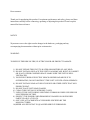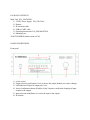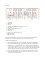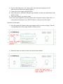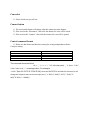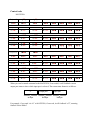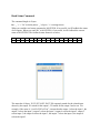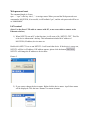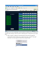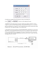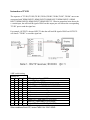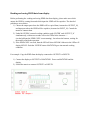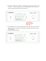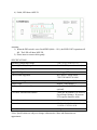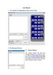
1
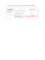
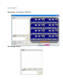
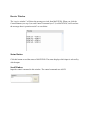
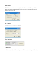
HDMI 8 x 8 Matrixes (Routing Type)
Model No. MAT8T820 (P/N of this Instructions is INS- MAT8T820)
Features
1) Allows up to eight HDMI audio/video devices to be independently switched to eight
HDMI monitors, HDTVs, or projectors.
2) The eight outputs could show the same or different source simultaneously no matter the
source is HDCP or not.
3) Each output includes one HDMI A type connecter and a set of dual RJ-45 connecters as
the second mirrored HDMI output. The two outputs work simultaneously. The UTP
output supports both dual and single cat5e/cat6
4) Reading and saving EDID function from displays.
5) Support high definition resolutions, including 1080p, 1080i, 720p and other standard
video formats.
6) Each port supports both HDMI and DVI inputs.
7) With extra infrared extension receiver.
8) Six switching modes: panel buttons, local IR, IR call back from remote locations, RS232,
RS485 and Ethernet.
9) Eight IR emitters to control the HDMI sources.
10) HDCP compliant.
11) HDMI 1.3 version.
Dear customer:
Thank you for purchasing this product. For optimum performance and safety, please read these
instructions carefully before connecting, operating or adjusting this product. Please keep this
manual for future reference.
NOTICE
Wyrestorm reserves the right to make changes in the hardware, packaging and any
accompanying documentation without prior written notice.
WARNING:
TO REDUCE THE RISK OF FIRE, ELECTRIC SHOCK OR PRODUCT DAMAGE:
1) DO NOT EXPOSE THIS UNIT TO WATER OR MOISTURE OF ANY KIND.
2) DO NOT INSTALL OR PLACE THIS UNIT IN A BOOKCASE, BUILT-IN CABINET
OR IN ANY OTHER CONFINED SPACE. MAKE SURE THE UNIT IS WELL
VENTILATED.
3) TO PREVENT RISK OF ELECTRIC SHOCK OR FIRE HAZARD DUE TO
OVERHEATING, DO NOT OBSTRUCT THE UNIT’S VENTILATION OPENINGS.
4) DO NOT INSTALL NEAR ANY HEAT SOURCE OR OTHER UNITS THAT MAY
PRODUCE HEAT.
5) DO NOT PLACE UNIT NEAR FLAMES.
6) CLEAN THIS UNIT ONLY WITH DRY CLOTH.
7) UNPLUG THIS UNIT DURING LIGHTNING STORMS OR WHEN UNUSED FOR
LONG PERIODS OF TIME.
8) PROTECT THE POWER CORD FROM BEING WALKED ON OR PINCHED
PARTICULARLY AT PLUGS.
9) ONLY USE ATTACHMENTS/ACCESSORIES SPECIFIED BY THE
MANUFACTURER.
10) REFER ALL SERVICING TO QUALIFIED SERVICE PERSONNEL.
TABLE OF CONTENTS
Introduction
Package Contents
Panel Descriptions
Connect and Operation
Specification
Typical Application
Maintenance
Product Service
Warranty
Contact Information
INTRODUCTION
Wyrestorm’s MAT8T820 is an 8-by-8 DVI/HDMI true matrix. It allows any of the eight source
(Blue-Ray player, HD DVD player, satellite receiver, game system, etc.) to be routed to any of
the eight displays simultaneously, no matter the source is HDCP or not. Users can choose several
different ways to control the matrix: by using infrared extension receiver, RS232, RS485, LAN,
and supplied remote control. IR emitters in the matrix are for controlling the sources; the IR
control signal could be from remote locations via STP/UTP type HDMI connection on the rear
panel.
MAT8T820 has the ability of equalization and amplification to ensure HDMI signal's
transmission through long cable without quality loss. The transmission distance of STP/UTP
outputs reaches up to 30 meters under the video format of 1080P, together with infrared control
signal.
MAT8T820offers solutions for digital entertainment center, HDTV retail and show site, HDTV,
STB, DVD and projector factory, noise, space and security concerns, data center control,
information distribution, conference room presentation, school and corporate training
environments.
PACKAGE CONTENTS
Main Unit. P/N_ MAT8T820.
1) 12VDC Power Supply. P/N_VDC1204
2) Remote.
3) IR extension cable.
4) USB to UART cable.
5) Operating Instructions. P/N_INS MAT8T820.
6) Mounting ears.
*PART NUMBER (Abbreviation as P/N).
PANEL DESCRIPTIONS
Front panel
1)
2)
3)
4)
Power switch.
Output selection push button (Use it to choose the output channel you want to change).
LED indicator of input for output port 1 to 8.
Action Confirmation button (Push the ‘Enter’ button to confirm the changing of input
channel to the output).
5) Input selection knob(Rotate it to select the input to the output)
6) IR window.
Rear panel
1) IR extension.
2) RS485 port.
3) LAN port.
4) IR emitter, corresponding to the Input port from 1 to 8
5) RS232 port.
6) Output 1 to 4 with HDMI and CAT5E.
7) Input ports 1 to 4.
8) Power input.
9) Output 5 and 8 with HDMI and CAT5E.
10) Input ports 5 to 8.
11) DIP switch setting.
Note: RS232 port and LAN port are for matrix control. The LAN port is connected to the
computer via cross UTP and connected to the router or switcher via direct UTP.
CONNECT AND OPERATION
1) Connect the HDMI input sources (such as HD-DVD, PS3, STB etc) into MAT8T820
2) Connect the standard HDMI outputs (such as HD-LCD, HD-DLP) into MAT8T820.
3) Connect two CAT-5E cables to both the STP/UTP outputs of MAT8T820and inputs of
STP/UTP receiver (such as EXT131/33/51/53 etc). Please pay attention to the sequence
of the two cables, CAT5e-1->CAT5e1, CAT5e-2->CAT5e2. (The cable termination must
follow the standard of EIA/TIA 568B, if Single UTP mode, just connect CAT5E-2)
4) Connect the HDMI output (such as: HD-LCD.HD-DLP) into the STP/UTP receiver.
5) Connect the IR RX receiving cable into STP/UTP receiver IR RX and connect The IR
TX cable into MAT8T820 IR emitter.
6) Power on the input source you want to show. (Keep the unused input power off,
otherwise it may interfere the normal display.)
7) Connect the power supply into MAT8T820
8) Turn on the power, when the LED panel stops flashing circularly, the initialization of the
matrix is ready.
9) Turn on the displays you want to watch.
10) Use the remote supplied or push the button on the front panel to choose input source, or
using infrared extension receiver, RS232, RS485 or LAN port to do the control.
Operation on front panel
1) Press the output select button to the output channel which you want to change. Then the
corresponding LED of the output channel will blink slowly.
2) Rotate the input select knob to choose the desired input channel.
3) Press the ‘Enter’ button to confirm the action. Then the LED stops blinking.
Control via RS232.
The Interface of MAT8T820_COMCTL
The Message Window
Receive Window
The “receive window” will show the message received from MAT8T820. When you click the
Control Buttons (see step 4) or send Control Command (see 2.3) to MAT8T820, it will send out
the message about “operation results” as seen below:
Status Button
Click this button to read the status of MAT8T820. The status displays which input is selected by
which output.
Send Window
Input the control command in this window. The control command uses ASCII.
Mode button
Click this button to set the switch mode: Quick switch or Normal switch. When you click this
button it will read the current mode of MAT8T820, if you want to change the mode, select the
mode you want and click OK.
Set IP button
Click this button to set IP address for NETCTL.
The Com Status
Connect state
1) Connect state shows if the com is open or not. If it is open, the state is green. Otherwise,
the state is red.
Com select
1) Select which com you will use.
Connect button
1) The word on this button will change when the connection state changes.
2) If the word reads “Disconnect”, then click this button, the com will be closed.
3) If the word reads “Connect”, then click this button, the com will be opened.
Control command format
1) Below are data format and baud rate setting for writing independent software.
Com port setting:
Baud Rate:
Data bits:
Parity:
Stop bits:
Flow control:
9600 bps
8 bits
None
1 bit
None
The command format as follow:
cir + ‘_’ + code + ‘↙’ “cir” is the key word, ‘_’ is Space, “Code”
is the Control code, ‘↙’ is carriage return. For example:
“cir 39↙”(hex: 63 69 72 20 33 39 0D 0A), when the MAT8T820 received this command ,it will
change the Outport4 status to the next input port. ( “c”-0x63,”I”-0x69,”r”-0x72,” “-0x20,”3”0x33,”9”-0x39, ‘↙’-0x0d0a)
Control code
MAT8T820:
Outport1
<“08”
>“09”
1“00”
2“01”
3“02”
4“03”
5“04”
6“05”
7“06”
8“07”
Outport2
1 “10”
< “18”
2 “11”
> “19”
3 “12”
4 “13”
5“14”
6“15”
7“16”
8“17”
Outport3
1 “20”
< “28”
2 “21”
> “29”
3 “22”
4 “23”
5“24”
6“25”
7“26”
8“27”
Outport4
< “38”
> “39”
1 “30”
2 “31”
3 “32”
4 “33”
5“34”
6“35”
7“36”
8“37”
Outport5
<“48”
>“49”
1“40”
2“41”
3“42”
4“43”
5“44”
6“45”
7“46”
8“47”
Outport6
1 “50”
< “58”
2 “51”
> “59”
3“52”
4 “53”
5“54”
6“55”
7“56”
8“57”
Outport7
1 “60”
< “68”
2 “61”
> “69”
3“62”
4 “63”
5“64”
6“65”
7“66”
8“67”
Outport8
1 “70”
< “78”
2 “71”
> “79”
3 “72”
4 “73”
5“74”
6“75”
7“76”
8“77”
When you send a control command to the MAT8T820, if successful, it will feedback current
output port status to show which input port is selected. The return status format is as follows:
“s”
1st byte
Output port
2nd byte
Input port
3rd byte
For example, if you send “cir 44.” to MAT8T820, if succeeds, it will feedback “s55”, meaning
OutPut5 selects InPut5.
Read Status Command
The command length is 4 bytes.
bc + ‘_’ + ‘↙’ “bc” is the key word, ‘_’ is Space, ‘↙’ is carriage return.
When you send the read status command to MAT8T820, if successful, it will feedback the status
of all outputs. When you send “Bc” to MAT8T820, if successful, it will feedback the current
status of MAT8T820. The feedback status format is as below,
1
2
3
‘\r’ ‘\n’ s
4
X1
5
6
X2 s
7
X3
8
X4
9
s
10
X5
11
X6
12
s
13
X7
14
X8
15 16
‘\r’ ‘\n’
The status has 16 bytes. X1,X2.X3,X4,X5,X6,X7,X8 separately stands for the related input
chosen by the output. X1 stands for the output 1, X2 stands for the output 2 and so on. For
example, if the status is “\r\ns12s22s53s45\r\n”, it means that the output 1 select the input 1, the
output 2 selects the input 2, output 3 selects the input 2, output 4 selects the input 2, output 5
selects input 5, the output 6 selects the input 3, the output 7 selects the input 4, the output 8
selects the input 5.
Web password reset
The command length is 4 bytes.
rpw+ ‘.’ “rpw” is the key word , ‘.’ is carriage return. When you send the Web password reset
command to MAT8T820, if successful, it will feedback "rpw", and the web password will be set
as “0000000000”.
LAN control
(Note: Use the direct UTP cable to connect with PC, or use cross cable to connect to the
Ethernet switcher)
1) When NETCTL run on PC at the first time, it will create a file ‘NETCTL.TXT’. This file
is for device information’s backup. This information includes MAC address of
MAT8T820, IP address, device name etc.
Double click NETCTL.exe to run NETCTL. It will search the device. If the device is a new one,
NETCTL will list it‘s IP address. If IP address appears, please click the button
NETCTL will change the IP address to device name.
.
Picture 2
2) If you want to change the device name. Right-click the device name. A pull down menu
will be displayed. Click the item ‘Rename’ to rename its name.
Picture 3
3) Double click the device name or right click and click the ‘open’. A web browser will be
shown. The default password is "0000000000", input the password and login. The device
controller page will be displayed.
Picture 4
The right area is for device controlling. Click these buttons to control the device. It is the same as
using the remote controller. The left area shows which input ports are being chosen by the output
ports.
4) When ‘Assign IP’ is displayed, it means that the device has not been assigned IP
automatically. Double click this item. Or right click and click ‘Assign IP’ on the pull
down menu. You can assign the IP address in the Assign IP dialog.
Click OK after assigning the new IP and return to the previous dialog box.
Click
and
. The device can be displayed correctly.
ATTENTION: In this application the assign IP is different from SetIP in COMCTL. SetIP in
COMCTL is used to save the IP address in flash, when the MAT8T820 power is on, it will read
the IP from flash and set it as static IP. Use the Assign IP function when the automatically obtain
IP address fails. This assigned IP address is not saving in flash.
11 IR call back from remote locations to control the HDMI Matrix MAT8T820. You can use the
MAT8T820’s remote through the IR RX of the UTP receiver to change the input channel for the
UTP out of the MAT8T820, just changing this UTP output. This function can be set on or off:
press the output1 button and the output8 button at the same time for about 3 seconds. The LEDs
will display ‘IR ON’ or ‘IR OFF’.
Instruction of TX IR
The sequence of "TX IR1,TX IR2,TX IR3,TX IR4,TX IR5,TX IR6,TX IR7, TX IR8" one-to-one
correspond with "HDMI INPUT1,HDMI INPUT2,HDMI INPUT3,HDMI INPUT4, HDMI
INPUT5,HDMI INPUT6,HDMI INPUT7,HDMI INPUT8". When an output has been chosen for
a certain input, the call-back IR signal of RJ45 on this output port will choose the corresponding
"TX IR" port to send the signal out.
For example, OUTPUT1 chooses INPUT3, then the call-back IR signal of RJ45 on OUTPUT1
will choose "TX IR3" to send the signal out.
9 DIP switch setting
Position ID
1
2
3
4
0
1
0
0
0
1
0
1
0
1
1
0
0
1
1
1
1
0
0
0
1
0
0
1
1
0
1
0
1
0
1
1
1
1
0
0
1
1
0
1
1
1
1
0
1
1
1
1
UTP output mode and EDID
Dual UTP, Fully COPY
Single UTP, Fully COPY
Dual UTP, limited TMDS CLK COPY EDID
Single UTP, limited TMDS CLK COPY EDID
Dual UTP, Fixed HMDI12_2CH EDID
Single UTP, Fixed HMDI12_2CH EDID
Dual UTP, Fixed HMDI12_6CH EDID
Single UTP, Fixed HMDI12_6CH EDID
Dual UTP, Fixed HMDI13_2CH EDID
Single UTP, Fixed HMDI13_2CH EDID
Dual UTP, Fixed HMDI13_6CH EDID
Single UTP, Fixed HMDI13_6CH EDID
Other conditions Dual UTP, limited TMDS CLK COPY EDID
Reading and saving EDID data from display
Before performing the reading and saving EDID data from display, please make sure which
output the EDID is coming from and which input the EDID will be copied to. The detailed
procedures are as below:
1) Choose the output port where the EDID will be copied from (Assumed as OUTPUT_N),
and input port where the EDID will be copied to (Assumed as INPUT_N). Control the
matrix to connect them.
2) Under MAT8T820’s normal working condition, push ‘ENTER’ and ‘OUTPUT_N’
simultaneously, within two seconds will see the LEDs lit the character ‘-‘
circularly(Means the EDID COPY is auto running). Just release the buttons, waiting for
the matrix to finish the operation.
3) If the EDID COPY succeeds, then the LED will show MIX OK. Otherwise the LEDs will
display MIX FL. Push the ‘ENTER’ button. MAT8T820 goes into normal working
condition.
For example: Copy the EDID from the display connected to OUTPUT1 to INPUT8.
1) Connect the display to OUTPUT1 of MAT8T820. Power on MAT8T820 and the
display.
2) Switch the matrix to connect OUTPUT1 to INPUT8.
3) Press down ‘ENTER’ and ‘OUTPUT_1’ simultaneously, after two seconds will see the
LEDs show ‘-‘circularly. (Means the matrix is performing EDID COPY). Release the
buttons, waiting the machine finish the remained work.
4) If the EDID COPY succeeds, the LEDs will show ‘MIX OK’; otherwise the LEDs will
display ‘MIX FL’. Then push the ‘ENTER’ button, MAT8T820 goes back to normal
working condition.
5) Succeed, LED shows MIX OK
6) Failed, LED shows MIX FL
Attention:
1) When the DIP switch is set to fixed EDID (1000---1111), the EDID COPY operation will
fail. The LED will show MIX FD.
2) Please insert or extract cables gently.
SPECIFICATIONS
Operating Temperature Range
-5 to +35°C (-41 to +95 °F)
Operating Humidity Range
5 to 90 % RH (no condensation)
Input Video Signal
0.5-1.0 volts p-p
Input DDC Signal
5 volts p-p (TTL)
Video Format Supported
DTV/HDTV: 1080P/1080i/
720P/576P/480P/576i/ 480i
Audio Format Supported
DTS-HD.Dolby tureHD.7.1ch
Output Video
HDMI1.2 and HDMI 1.3
Maximum Transmission Distance
<15m (If needed, HDMI extender is
optional)
UTP cable Transmission Distance
<40m (use Wyrestorm UTP receiver,
if need longer distance, Wyrestorm
UTP repeater should be used)
Power Consumption
35wtts (Max)
Dimensions
282.58mmD×438.15mmW×141.2mmH/
11.125''D×17.25''W×5.56''H
Mass (Main Unit)
3.4kg
*Note: Specifications are subject to change without notice. Mass and dimensions are
approximate.
MAINTENANCE
Clean this unit with a soft, dry cloth. Never use alcohol, paint thinner or benzene to clean this
unit.
PRODUCT SERVICE
1) Damage requiring service: The unit should be serviced by qualified service personnel if:
a) The DC power supply cord or AC adaptor have been damaged;
b) Objects or liquids have gotten into the unit;
c) The unit has been exposed to water;
d) The unit does not operate normally or exhibits a marked change in performance;
e) The unit has been dropped or the cabinet has been damaged.
2) Servicing Personnel: Do not attempt to service the unit beyond that described in these
operating instructions. Refer all other servicing to authorized servicing personnel.
3) Replacement parts: When parts need replacing make sure the servicer uses parts specified
by the manufacturer or parts that have the same characteristics as the original parts.
Unauthorized substitutes may result in fire, electric shock, or other hazards.
4) Safety check: After repairs or service, ask the servicer to perform safety checks to
confirm that the unit is in proper working condition.
WARRANTY
If your product does not work properly because of a defect in materials or workmanship,
Wyrestorm (referred to as “the warrantor”) will, for the length of the period indicated as below,
(Parts and Labor (2) Year) which starts with the date of original purchase (“Limited Warranty
period”), at its option either (a) repair your product with new or refurbished parts, or (b) replace
it with a new or a refurbished product. The decision to repair or replace will be made by the
warrantor.
During the “Labor” Limited Warranty period there will be no charge for labor.
During the “Parts” warranty period, there will be no charge for parts. You must mail-in your
product during the warranty period. This Limited Warranty is extended only to the original
purchaser and only covers product purchased as new. A purchase receipt or other proof of
original purchase date is required for Limited Warranty service.
Mail-In Service
Please contact our customer service department describing the issue, and a new product will be
sent to you immediately with an applicable charge. Please place the damaged product in the new
package and send back with the return shipping label provided. Once the damaged product is
received, a reimbursement will be provided. Include a letter detailing the complaint and provide
a day time phone and/or email address where you can be reached.
IF REPAIR IS NEEDED DURING THE LIMITED WARRANTY PERIOD, THE
PURCHASER WILL BE REQUIRED TO FURNISH A SALES RECEIPT/PROOF
OF PURCHASE INDICATING DATE OF PURCHASE, AMOUNT PAID AND
PLACE OF PURCHASE. CUSTOMER WILL BE CHARGED FOR THE REPAIR
OF ANY UNIT RECEIVED WITHOUT SUCH PROOF OF PURCHASE.
LIMITED WARRANTY LIMITS AND EXCLUSIONS
1) This Limited Warranty ONLY COVERS failures due to defects in materials or workmanship,
and DOES NOT COVER normal wear and tear or cosmetic damage. The Limited Warranty
ALSO DOES NOT COVER failures which are caused by products not supplied by the
warrantor, or failures which result from accidents, misuse, abuse, neglect, mishandling,
misapplication, alteration, faulty installation, set-up adjustments, misadjustment of consumer
controls, improper maintenance, power line surge, lightning damage, modification, or service by
anyone other than a Factory Servicenter or other Authorized Servicer, or damage that is
attributable to acts of God.
2) THERE ARE NO EXPRESS WARRANTIES EXCEPT AS LISTED UNDER “LIMITED
WARRANTY COVERAGE.” THE WARRANTOR IS NOT LIABLE
FOR INCIDENTAL OR CONSEQUENTIAL DAMAGES RESULTING FROM THE USE OF
THIS PRODUCT, OR ARISING OUT OF ANY BREACH OF THIS WARRANTY. (As
examples, this excludes damages for lost time, cost of having someone remove or re-install an
installed unit if applicable, travel to and from the servicer, loss of or damage to media or images,
data or other recorded content. The items listed are not exclusive, but are for illustration only.)
3) PARTS AND SERVICE, WHICH ARE NOT COVERED BY THIS LIMITED
WARRANTY, ARE YOUR RESPONSIBILITY.
Thank you for your purchase.
We appreciate your business. Please contact us with your question and comments.
WyreStorm
6755 Buckles Cove
Memphis, TN 38133
1-877-HDMI WYRE – Toll Free
901-363-0111 – Office Phone
901-363-0115 – Office Fax
Email: [email protected]
Website: www.WyreStorm.com