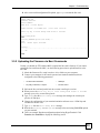
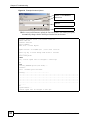
1
ALC1248G
ADSL2/2+ Line Card
User’s Guide
Version 3.90
3/2008
Edition 1
www.zyxel.com
About This User's Guide
About This User's Guide
Intended Audience
This manual is intended for users of the ALC1248G ADSL2/2+ Line Card. It describes
detailed information about the cards’ features and hardware.
Related Documentation
• IES-5000 and IES-6000 User’s Guides
Refer to the IES-5000 or the IES-6000 User’s Guide for directions on installation,
connections, maintenance, hardware trouble shooting and safety warnings.
• MSC1000G and MSC1024G Management Switch Card User’s Guides
These user’s guides cover the configuration of your IES-5000 or IES-6000. Refer to these
user’s guides for information on your ALC’s default settings.
• ZyXEL Web Site
Please refer to www.zyxel.com for additional support documentation and product
certifications.
User Guide Feedback
Help us help you. Send all User Guide-related comments, questions or suggestions for
improvement to the following address, or use e-mail instead. Thank you!
The Technical Writing Team,
ZyXEL Communications Corp.,
6 Innovation Road II,
Science-Based Industrial Park,
Hsinchu, 300, Taiwan.
E-mail: [email protected]
ALC1248G User’s Guide
3
Document Conventions
Document Conventions
Warnings and Notes
These are how warnings and notes are shown in this User’s Guide.
1
"
Warnings tell you about things that could harm you or your device.
Notes tell you other important information (for example, other things you may
need to configure or helpful tips) or recommendations.
Syntax Conventions
• The ALC1248G may be referred to as the “ALC”, the “device” or the “system” in this
User’s Guide.
• The “ALC1248G”, the “ALC” and the “line card” refer to the ALC1248G-51 for ADSL
over POTS (Annex A). They also refer to the ALC1248G-53 for ADSL over ISDN
(Annex B). Differentiation is made where needed.
• “IES” refers to the IES-5000 or IES-6000 system, including the main chassis and all
associated cards.
• “MSC” refers to the MSC1000G or MSC1024G management switch card.
• Product labels, screen names, field labels and field choices are all in bold font.
• A key stroke is denoted by square brackets and uppercase text, for example, [ENTER]
means the “enter” or “return” key on your keyboard.
• “Enter” means for you to type one or more characters and then press the [ENTER] key.
“Select” or “choose” means for you to use one of the predefined choices.
• A right angle bracket ( > ) within a screen name denotes a mouse click. For example,
Maintenance > Log > Log Setting means you first click Maintenance in the navigation
panel, then the Log sub menu and finally the Log Setting tab to get to that screen.
• Units of measurement may denote the “metric” value or the “scientific” value. For
example, “k” for kilo may denote “1000” or “1024”, “M” for mega may denote “1000000”
or “1048576” and so on.
4
ALC1248G User’s Guide
Safety Warnings
Safety Warnings
1
For your safety, be sure to read and follow all warning notices and instructions.
• Do NOT use this product near water, for example, in a wet basement or near a swimming
pool.
• Do NOT expose your device to dampness, dust or corrosive liquids.
• Do NOT store things on the device.
• Do NOT install, use, or service this device during a thunderstorm. There is a remote risk
of electric shock from lightning.
• Connect ONLY suitable accessories to the device.
• Do NOT open the device or unit. Opening or removing covers can expose you to
dangerous high voltage points or other risks. ONLY qualified service personnel should
service or disassemble this device. Please contact your vendor for further information.
• Make sure to connect the cables to the correct ports.
• Place connecting cables carefully so that no one will step on them or stumble over them.
• Always disconnect all cables from this device before servicing or disassembling.
• Do not use the device outside, and make sure all the connections are indoors. There is a
remote risk of electric shock from lightning.
• Do NOT obstruct the device ventilation slots, as insufficient airflow may harm your
device.
• Warning! To avoid risk of electric shock, remove only one card at a time and do not place
fingers or objects inside the chassis. Cover empty slots with slot covers.
This product is recyclable. Dispose of it properly.
ALC1248G User’s Guide
5
Safety Warnings
6
ALC1248G User’s Guide
Table of Contents
Table of Contents
About This User's Guide .......................................................................................................... 3
Document Conventions............................................................................................................ 4
Safety Warnings....................................................................................................................... 5
Table of Contents...................................................................................................................... 7
List of Figures ........................................................................................................................... 9
List of Tables........................................................................................................................... 11
Chapter 1
Introducing the ALC1248G..................................................................................................... 13
1.1 ALC1248G Overview ........................................................................................................... 13
1.2 ADSL Standards Overview .................................................................................................. 13
1.3 Features .............................................................................................................................. 14
1.4 Front Panel ......................................................................................................................... 18
1.5 Ports and LEDs ................................................................................................................... 18
1.5.1 Ports ........................................................................................................................... 18
1.5.2 LEDs ......................................................................................................................... 19
1.6 Default Settings .................................................................................................................. 19
Chapter 2
Product Specifications ........................................................................................................... 21
2.1 Product Specifications ......................................................................................................... 21
2.2 Firmware Naming Conventions ........................................................................................... 23
2.3 Telco-50 Connector Pin Assignments .................................................................................. 24
2.4 Wire Gauge Specifications .................................................................................................. 27
2.5 Console Cable Pin Assignments ......................................................................................... 27
Chapter 3
Troubleshooting...................................................................................................................... 29
3.1 Power and LEDs .................................................................................................................. 29
3.2 DSL Data Transmission ....................................................................................................... 30
3.3 Local Server ........................................................................................................................ 30
3.4 Data Rate ........................................................................................................................... 31
3.5 Management and Configuration .......................................................................................... 31
3.5.1 Uploading the Default Configuration File via Boot Commands .................................. 32
3.5.2 Uploading the Firmware via Boot Commands ............................................................ 33
ALC1248G User’s Guide
7
Table of Contents
Appendix A Legal Information ................................................................................................ 35
Appendix B Customer Support............................................................................................... 39
Index......................................................................................................................................... 45
8
ALC1248G User’s Guide
List of Figures
List of Figures
Figure 1 Front Panel ............................................................................................................................... 18
Figure 2 ALC Ports 1-24 Telco-50 Connector Pin Assignments ........................................................... 24
Figure 3 ALC Ports 25-48 Telco-50 Connector Pin Assignments .......................................................... 24
Figure 4 IES-5000/5005 Cable Telco-50 Pin Assignments (ALC End) ................................................... 25
Figure 5 IES-5000/5005 Cable Telco-50 Pin Assignments (Splitter Card End) ...................................... 26
Figure 6 IES-6000 Cable Telco-50 Pin Assignments (ALC End) ............................................................ 26
Figure 7 IES-6000 Cable Telco-50 Pin Assignments (Splitter Card End) ............................................... 27
Figure 8 Console Cable Mini RJ-11 Male Connector ............................................................................. 28
Figure 9 Example Xmodem Upload ........................................................................................................ 32
Figure 10 Example Xmodem Upload ...................................................................................................... 34
ALC1248G User’s Guide
9
List of Figures
10
ALC1248G User’s Guide
List of Tables
List of Tables
Table 1 ADSL Standards Maximum Transfer Rates .............................................................................. 13
Table 2 Front Panel Ports ...................................................................................................................... 18
Table 3 LED Descriptions ...................................................................................................................... 19
Table 4 Device Specifications ................................................................................................................ 21
Table 5 Supported Standards ................................................................................................................ 22
Table 6 ALC Telco-50 Connector Pin Assignments ............................................................................... 24
Table 7 Wire Gauge Specifications ........................................................................................................ 27
Table 8 Console Cable Connector Pin Assignments ............................................................................. 28
Table 9 SYS LED Troubleshooting ........................................................................................................ 29
Table 10 ALM LED Troubleshooting ...................................................................................................... 30
Table 11 DSL Data Transmission Troubleshooting ................................................................................ 30
Table 12 Local Server Troubleshooting ................................................................................................. 31
Table 13 SYNC-rate Troubleshooting .................................................................................................... 31
ALC1248G User’s Guide
11
List of Tables
12
ALC1248G User’s Guide
CHAPTER
1
Introducing the ALC1248G
This chapter introduces the ADSL2/2+ line card's general features, factory default settings and
hardware.
1.1 ALC1248G Overview
The ALC1248G ADSL2/2+ Line Card is perfect for ISPs or large building applications
seeking to provide high bandwidth broadband services to subscribers while minimizing costs.
One ALC provides ADSL service for 48 subscribers over existing telephone wiring, thus
avoiding the cost and hassle of installing new wiring.
The line from the user carries both the ADSL and the voice signals. For each line, the splitter
card separates the high frequency ADSL signal from the voice band signal and feeds the
ADSL signal to the line card, while the voice band signal is diverted to the central office
switch or PBX (Private Branch Exchange).
Use the Telco-50 connector pin assignments in Section 2.3 on page 24 along with the
directions and safety warnings in the IES User's Guide to install the line card and make the
necessary connections.
See the MSC User’s Guide for detailed information on configuring the line card.
1.2 ADSL Standards Overview
These are the ADSL standards and rates that the ADSL line card supports at the time of
writing. The actual transfer rates will vary depending on what the subscriber’s device
supports, the line conditions and the connection distance.
Table 1 ADSL Standards Maximum Transfer Rates
STANDARD
MAXIMUM DOWNSTREAM
MAXIMUM UPSTREAM
G.dmt
8160 Kbps
1024 Kbps
ANSI T1.413 issue 2
8160 Kbps
1024 Kbps
G.lite
1536 Kbps
512 Kbps
ADSL2
12000 Kbps
1200 Kbps
ADSL2 Annex M
12000 Kbps
2400 Kbps
ADSL2+
25000 Kbps
1200 Kbps
ADSL2+ Annex M
25000 Kbps
2400 Kbps
ALC1248G User’s Guide
13
Chapter 1 Introducing the ALC1248G
1.3 Features
Here is a partial list of the ALC’s features.
ADSL Compliance
• Multi-Mode ADSL Standard
-DMT T1.413, issue 2
-G.DMT (ITU G.992.1) Annex A
-G.DMT (ITU G.992.1) Annex B
-G.LITE (ITU G.992.2)
• ADSL2
-G.992.3 Annex A
-G.992.3 Annex B
-G.992.3 Annex L
-G.992.3 Annex M
• ADSL2+
-G.992.5 Annex A
-G.992.5 Annex B
-G.992.5 Annex M
IEEE 802.1p Priority
The system uses IEEE 802.1p priority to assign priority levels to individual PVCs. The system
can also handle multiple IEEE 802.1p priority queues on a single PVC.
System Monitoring
• System status (link status, rates, statistics counters)
• Temperatures, voltage reports and alarms.
System Error Logging
The ALC's system error log will record error logs locally. These logs may be viewed again
after a warm restart.
Configurable Alarms
The system allows you to customize the priority levels of individual alarms and the alarm
severity threshold for recording alarms on an individual port(s).
Alarm LED
An ALM (alarm) LED lights when the ALC is overheated, the voltage readings are outside the
tolerance levels, a fan fails, or another alarm with a severity level of MAJOR or CRITICAL
occurs.
IEEE 802.1Q Tagged VLAN
Your ALC uses the IEEE 802.1Q Tagged VLAN (Virtual Local Area Network), which allows
it to deliver tagged/untagged frames to and from its ports. The IES supports up to 4094
individual VLANs.
14
ALC1248G User’s Guide
Chapter 1 Introducing the ALC1248G
Multicast VLAN
Multicast VLAN is designed for applications (such as Media-on-Demand (MoD)) using
multicast traffic across an Ethernet ring-based service provider network. Multicast VLAN
allows one single multicast VLAN to be shared among different subscriber VLANs on the
network. This improves bandwidth utilization by reducing multicast traffic in the subscriber
VLANs and simplifies multicast group management.
IEEE 802.1x Port-based Authentication
The ALC supports the IEEE 802.1x standard for centralized user authentication and
accounting management through an optional network authentication (RADIUS) server.
Port Isolation
The ALC's port isolation feature allows each port to communicate with the uplink port but not
communicate with each other. This option is the most limiting but also the most secure.
Isolation (per-VLAN)
Use isolation to block the DSL subscribers in a specific VLAN from sending traffic directly to
each other.
Packet Filter
The ALC supports packet filtering based on protocol. You can configure the ALC to accept all
packets, accept PPPoE packets only or block any combination of the following protocols: IP,
ARP, DHCP, EAPOL, PPPoE, NetBios or IGMP.
MAC (Media Access Control) Filters
Use the MAC filter to filter incoming frames based on MAC (Media Access Control)
address(es) or the OUI (Organizational Unit Identifier) that you specify. You may enable/
disable the MAC filter on specific ports. You may specify up to ten MAC addresses per port.
MAC (Media Access Control) Count Limit
You can limit the number of MAC addresses that may be dynamically learned on a port. You
may enable/disable the MAC count limit on individual ports.
IGMP Snooping
The ALC supports IGMP snooping enabling group multicast traffic to be only forwarded to
ports that are members of that group; thus allowing you to significantly reduce multicast
traffic passing through your ALC.
IGMP Filter
The IGMP filter defines multicast groups a port can join. You can create IGMP filter profiles
which allow access to a multicast group, then assign the IGMP filter to a specific DSL port.
Multicast Group Limit
You can limit the number of IGMP multicast groups a subscriber on a port can join. You may
enable/disable the multicast group limit on individual ports.
ALC1248G User’s Guide
15
Chapter 1 Introducing the ALC1248G
Discarding of IGMP Query Messages
The ALC discards IGMP query messages received from subscriber ports. This prevents
subscribers from hosting IGMP multicast servers.
IGMP Statistics
The ALC records the number of active users in an IGMP multicast channel (multicast group).
The ALC also records IGMP message statistics on a per port basis to ease management and
troubleshooting.
IGMP Message Rate Limiting
The ALC can limit how many IGMP message packets a subscriber can send per second. This
prevents subscribers from flooding the multicast server.
DLS Bonding (G.bond)
Bond two DSL ports for higher throughput. Packets can still pass through a single line if one
of the links goes down.
Static Multicast
Use static multicast to allow incoming frames based on multicast MAC address(es) that you
specify. This feature can be used in conjunction with IGMP snooping to allow multicast MAC
address(es) that are not learned by IGMP snooping. You can use static multicast to pass
routing protocols, such as RIP and OSPF.
Multicast Bandwidth Control
The ALC supports static bandwidth control for multicast traffic. Bandwidth limits can be
assigned to multicast channels. During IGMP snooping, the system checks the total bandwidth
usage to see if it exceeds the specified limit. If the specified limits are reached, the system
restricts the joining of multicast groups.
DHCP Relay
DHCP (Dynamic Host Configuration Protocol RFC 2131 and RFC 2132) allows individual
computers to obtain TCP/IP configuration at start-up from a server. You can configure the
system as a DHCP relay agent to have another DHCP server provide TCP/IP configuration for
the clients. In addition, you can set the system to forward client DHCP requests to specific
DHCP servers based on the VLAN ID. You can also specify up to two DHCP servers for each
VLAN to provide failover protection.
DHCP Relay Option82
The system supports DHCP relay agent82 (RFC 3046) that adds additional information to
client DHCP requests that the MSC relays to a DHCP server. It also supports adding the suboption 2 (Remote ID) with additional information.
DHCP Snooping
DHCP snooping allows the system to identify packets with DHCP server assigned IP
address(es) and block access of devices using unknown IP addresses on a subscriber port. You
can also manually add static IP addresses to the DHCP snooping table.
16
ALC1248G User’s Guide
Chapter 1 Introducing the ALC1248G
System Error Logging
The system error log will record error logs locally to the management switch card memory.
Remote Firmware Upgrade
You can use FTP or SFTP to perform configuration backup/restore and firmware upgrade
from a remote location.
Anti-IP Address Spoofing
With DHCP snooping, the ALC records which IP addresses are assigned on each port. The
ALC drops packets from a device using a different IP address.
Anti-MAC Address Spoofing
The ALC checks to make sure the MAC addresses of the devices connected to the DSL ports
are not the same as MAC addresses of devices connected to the Ethernet network. This
protects the network from disruptions of service caused by subscriber devices spoofing the
MAC address of ISP servers.
Multiple PVC and ATM QoS
The ALC allows you to use different channels (also called Permanent Virtual Circuits or
PVCs) for different services or subscribers. Define channels on each DSL port for different
services or levels of service and assign each channel a priority. ATM Quality of Service (QoS)
allows you to regulate the average rate and fluctuations of data transmission. This helps
eliminate congestion to allow the transmission of real time data (such as audio and video).
Priority-based PVCs
The system provides Priority-based PVCs (PPVCs) to give different priorities to PVCs that are
members of the same VLAN. Use up to eight priority queues for the member PVCs. The
system maps frames with certain IEEE 802.1p priorities to a PVC with a particular priority
queue.
PPPoA-to-PPPoE (PAE) PVC
This feature allows the system to translate PPPoA packets to PPPoE packets (and vice versa)
to allow communication between CPE clients and an access concentrator (such as a BRAS)
through the switch.
PPPoE Intermediate Agent Information
Similar to DHCP relay option82, you can set the system to insert line information into client
PPPoE Discover Initialization (PODI) packets. This allows a PPPoE termination server to
identify and authenticate a PPPoE client.
Transparent LAN Service (TLS)
Use TLS (also known as VLAN stacking) to add an outer VLAN tag to the inner IEEE 802.1Q
tagged frames that enter the network. By tagging the tagged frames (“double-tagged” frames),
the service provider can manage up to 4,094 VLAN groups with each group containing up to
4,094 customer VLANs. This allows a service provider to provide different services based on
specific VLANs, for many different customers.
ALC1248G User’s Guide
17
Chapter 1 Introducing the ALC1248G
IP-aware Bridging
The line cards can forward frames based on the destination IP address, instead of the
destination MAC address, and replace the source MAC address with its own MAC address.
This provides better scalability and security for large-scale access networks, especially with
Ethernet.
Classifier and Policy
You can create a policy to define actions to be performed on a PVC traffic flow grouped by a
classifier according to specific criteria such as the IP address, port number or protocol type,
and so on.
Single End Loop Test (SELT)
This feature checks the distance to an ADSL subscriber’s location.
Double End Loop Test (DELT)
This feature (also called a Loop Diagnostic Mode test or LDM test) provides details about the
condition of an ADSL subscriber’s line.
1.4 Front Panel
The figure below shows the front panel of the ALC.
Figure 1 Front Panel
1.5 Ports and LEDs
These are the details of the ALC1248G ports and LEDs.
1.5.1 Ports
The following table describes the port labels on the front panel.
Table 2 Front Panel Ports
18
LABEL
DESCRIPTION
CONSOLE
For troubleshooting purposes, this mini RJ-11port connects to a computer
when the line card is not manageable from the MSC.
1-24, 25-48
These Telco-50 connectors are for connecting the ALC to the splitter cards.
ALC1248G User’s Guide
Chapter 1 Introducing the ALC1248G
1.5.2 LEDs
The following table describes the LED indicators on the front panel of the ALC.
Table 3 LED Descriptions
LED
COLOR
STATUS
DESCRIPTION
PWR
Green
On
The line card is turned on.
Off
The line card is off.
Blinking
The line card is rebooting and performing self-diagnostic
tests.
On
The line card is on and functioning properly.
Off
The power is off or the line card is malfunctioning.
On
There is a hardware failure or an alarm.
Off
The line card is functioning normally.
SYS
ALM
Green
Red
1.6 Default Settings
Refer to your MSC user’s guide for information on default settings.
ALC1248G User’s Guide
19
Chapter 1 Introducing the ALC1248G
20
ALC1248G User’s Guide
CHAPTER
2
Product Specifications
This chapter gives details about the line card hardware and features.
2.1 Product Specifications
Table 4 Device Specifications
Dimensions
390.6 mm (W) x 231.0 mm (D) x 24.0 mm (H)
Weight
0.5 kg
Interface
•
•
MAC Address Table
Up to 16K entries
Max. Number of IGMP
Filter Profiles
128
Operation Temperature
-40º C ~ 65º C
Storage Temperature
-40º C ~ 70º C
Operation Humidity
10% ~ 90% RH (non-condensing)
Storage Humidity
10% ~ 95% RH (non-condensing)
ADSL Compliance
Multi-Mode ADSL Standard
• DMT T1.413, issue 2
• G.DMT (ITU G.992.1) Annex A
• G.DMT (ITU G.992.1) Annex B
• G.LITE (ITU G.992.2)
ADSL2
• G.992.3 Annex A
• G.992.3 Annex B
• G.992.3 Annex L
• G.992.3 Annex M
ADSL2+
• G.992.5 Annex A
• G.992.5 Annex B
• G.992.5 Annex M
ALC1248G User’s Guide
Two Telco-50 connectors: 48 ADSL Ports
One mini RJ11 console port for local management
21
Chapter 2 Product Specifications
Table 4 Device Specifications
Certifications
CE Conformity
FCC
ITU-T K.20
Safety
IEC 60950-1
EN 60950-1
CSA 60950-1
UL 60950-1
EMC
EN 300386
EN 55022
EN 61000-3-2
EN 61000-3-3
EN 55024
Other Features
•
•
•
•
•
•
•
•
•
•
•
•
•
•
•
•
•
•
•
•
DLS Bonding (G.bond)
Anti-IP Address Spoofing
Anti-MAC Address Spoofing
MAC Filtering
MAC Count Limiting
Hardware-based Multicasting
Multicast Group Limit
IGMP Message Rate Limiting
IEEE 802.1Q VLAN Tagging
GVRP
IEEE 802.1p CoS with Priority Queuing
IEEE 802.1w RSTP
IEEE 802.1s MSTP
IGMP v1 & v 2 Snooping
DHCP Relay Option82
DHCP Snooping
IEEE 802.1x Port-based Authentication
PPPoA-PPPoE PVC
SELT (Single End Loop Test)
ACL profile
This table lists the standards the ALC supports.
Table 5 Supported Standards
22
STANDARD
DESCRIPTION
RFC 867
RFC 868
RFC 1305
Daytime protocol
Time protocol
Network Time Protocol (NTP)
RFC 1112
RFC 2236
RFC 3376
Internet Group Multicast Protocol (IGMP)
IGMP v2
IGMP v3
RFC 1213
RFC 1573
RFC 1757
RFC 2662
RFC 2674
RFC 2863
RFC 3440
RFC 3635
RFC 3636
Simple Network Management Protocol (SNMP)
ALC1248G User’s Guide
Chapter 2 Product Specifications
Table 5 Supported Standards (continued)
STANDARD
DESCRIPTION
RFC 1483
Multiprotocol Encapsulation over ATM Adaptation Layer 5
RFC 2131
RFC 2132
RFC 3046
Dynamic Host Configuration Protocol (DHCP)
RFC 2138
RFC 2139
Remote Authentication Dial In User Service (RADIUS)
RFC 2486
Extensible Authentication Protocol (EAP)
RFC 2684
LLC and VC MUX Bridging
IEEE 802.1d
Transparent Bridging
IEEE 802.1p
Layer 2 Traffic Prioritization
IEEE 802.1Q
Virtual Local Area Network (VLAN)
IEEE 802.1x
Network Authentication
2.2 Firmware Naming Conventions
A firmware version includes the model code and release number as shown in the following
example.
Firmware Version: V3.90(ABD.0), V3.90(ABE.0)
"ABD" or "ABE" is the model code.
• "ABD" denotes the ALC1248G-51 for ADSL over POTS (Annex A).
• "ABE" denotes the ALC1248G-53 for ADSL over ISDN (Annex B).
"0" is this firmware's release number. This varies as new firmware is released. Your
firmware's release number may not match what is displayed in this User's Guide.
ALC1248G User’s Guide
23
Chapter 2 Product Specifications
2.3 Telco-50 Connector Pin Assignments
The following figures and table describe the pin assignments for the ALC’s Telco-50
connectors. The splitter card’s Telco-50 connector and the USER and CO hardware Telco-50
connectors on the rear panel of the splitter chassis also use the same pin assignments.
Figure 2 ALC Ports 1-24 Telco-50 Connector Pin Assignments
Figure 3 ALC Ports 25-48 Telco-50 Connector Pin Assignments
Table 6 ALC Telco-50 Connector Pin Assignments
24
PORTS 1-24
(FIRST TELCO-50 CONNECTOR)
PORTS 25-48
(SECOND TELCO-50 CONNECTOR)
Pin 1
NULL
Pin 26 NULL
Pin 1
NULL
Pin 26
NULL
Pin 2
Ring Port 24
Pin 27 Tip Port 24
Pin 2
Ring Port 48
Pin 27
Tip Port 48
Pin 3
Ring Port 23
Pin 28 Tip Port 23
Pin 3
Ring Port 47
Pin 28
Tip Port 47
Pin 4
Ring Port 22
Pin 29 Tip Port 22
Pin 4
Ring Port 46
Pin 29
Tip Port 46
Pin 5
Ring Port 21
Pin 30 Tip Port 21
Pin 5
Ring Port 45
Pin 30
Tip Port 45
Pin 6
Ring Port 20
Pin 31 Tip Port 20
Pin 6
Ring Port 44
Pin 31
Tip Port 44
Pin 7
Ring Port 19
Pin 32 Tip Port 19
Pin 7
Ring Port 43
Pin 32
Tip Port 43
Pin 8
Ring Port 18
Pin 33 Tip Port 18
Pin 8
Ring Port 42
Pin 33
Tip Port 42
ALC1248G User’s Guide
Chapter 2 Product Specifications
Table 6 ALC Telco-50 Connector Pin Assignments (continued)
PORTS 1-24
(FIRST TELCO-50 CONNECTOR)
PORTS 25-48
(SECOND TELCO-50 CONNECTOR)
Pin 9
Ring Port 17
Pin 34 Tip Port 17
Pin 9
Ring Port 41
Pin 34
Tip Port 41
Pin 10
Ring Port 16
Pin 35 Tip Port 16
Pin 10
Ring Port 40
Pin 35
Tip Port 40
Pin 11
Ring Port 15
Pin 36 Tip Port 15
Pin 11
Ring Port 39
Pin 36
Tip Port 39
Pin 12
Ring Port 14
Pin 37 Tip Port 14
Pin 12
Ring Port 38
Pin 37
Tip Port 38
Pin 13
Ring Port 13
Pin 38 Tip Port 13
Pin 13
Ring Port 37
Pin 38
Tip Port 37
Pin 14
Ring Port 12
Pin 39 Tip Port 12
Pin 14
Ring Port 36
Pin 39
Tip Port 36
Pin 15
Ring Port 11
Pin 40 Tip Port 11
Pin 15
Ring Port 35
Pin 40
Tip Port 35
Pin 16
Ring Port 10
Pin 41 Tip Port 10
Pin 16
Ring Port 34
Pin 41
Tip Port 34
Pin 17
Ring Port 9
Pin 42 Tip Port 9
Pin 17
Ring Port 33
Pin 42
Tip Port 33
Pin 18
Ring Port 8
Pin 43 Tip Port 8
Pin 18
Ring Port 32
Pin 43
Tip Port 32
Pin 19
Ring Port 7
Pin 44 Tip Port 7
Pin 19
Ring Port 31
Pin 44
Tip Port 31
Pin 20
Ring Port 6
Pin 45 Tip Port 6
Pin 20
Ring Port 30
Pin 45
Tip Port 30
Pin 21
Ring Port 5
Pin 46 Tip Port 5
Pin 21
Ring Port 29
Pin 46
Tip Port 29
Pin 22
Ring Port 4
Pin 47 Tip Port 4
Pin 22
Ring Port 28
Pin 47
Tip Port 28
Pin 23
Ring Port 3
Pin 48 Tip Port 3
Pin 23
Ring Port 27
Pin 48
Tip Port 27
Pin 24
Ring Port 2
Pin 49 Tip Port 2
Pin 24
Ring Port 26
Pin 49
Tip Port 26
Pin 25
Ring Port 1
Pin 50 Tip Port 1
Pin 25
Ring Port 25
Pin 50
Tip Port 25
The following graphics show pin assignments for the Telco-50 connectors on the cables that
connect the ALC to a splitter card in the splitter chassis. The pin assignments for ports 25-48
follow the same pattern as the pin assignments for ports 1-24.
Figure 4 IES-5000/5005 Cable Telco-50 Pin Assignments (ALC End)
ALC1248G User’s Guide
25
Chapter 2 Product Specifications
Figure 5 IES-5000/5005 Cable Telco-50 Pin Assignments (Splitter Card End)
Figure 6 IES-6000 Cable Telco-50 Pin Assignments (ALC End)
26
ALC1248G User’s Guide
Chapter 2 Product Specifications
Figure 7 IES-6000 Cable Telco-50 Pin Assignments (Splitter Card End)
2.4 Wire Gauge Specifications
AWG (American Wire Gauge) is a measurement system for wire that specifies its thickness.
As the thickness of the wire increases, the AWG number decreases.
Table 7 Wire Gauge Specifications
WIRE TYPE
REQUIRED AWG NO. (DIAMETER)
Telephone Wire
26 or larger
2.5 Console Cable Pin Assignments
The following diagram and chart show the pin assignments of the console cable.
ALC1248G User’s Guide
27
Chapter 2 Product Specifications
Figure 8 Console Cable Mini RJ-11 Male Connector
Table 8 Console Cable Connector Pin Assignments
MINI RJ-11 MALE
Pin 2: TXD
Pin 3: RXD
Pin 4: GND
28
ALC1248G User’s Guide
CHAPTER
3
Troubleshooting
This chapter offers some suggestions to solve problems you might encounter. The potential
problems are divided into the following categories.
•
•
•
•
•
Power and LEDs
DSL Data Transmission
Local Server
Data Rate
Management and Configuration
3.1 Power and LEDs
V
The SYS or PWR LED does not turn on.
Table 9 SYS LED Troubleshooting
V
STEPS
CORRECTIVE ACTION
1
Make sure the power wires are properly connected to the power supply and the power
supply is operating normally. Make sure you are using the correct power source (refer to
the IES User’s Guide).
2
Make sure the power wires are connected properly.
3
Make sure the line card is properly installed.
4
The LED itself or the unit may be faulty; contact your vendor.
The ALM LED is on.
ALC1248G User’s Guide
29
Chapter 3 Troubleshooting
The ALM (alarm) LED lights when the line card is overheated or the voltage readings are
outside the tolerance levels.
Table 10 ALM LED Troubleshooting
STEPS
CORRECTIVE ACTION
1
Use the sys monitor status command to verify the cause of the alarm. See step 2 if
the unit is overheated, and step 3 if the voltages are out of the allowed ranges.
2
Ensure that the IES is installed in a well-ventilated area and that normal operation of the
fans is not inhibited. Keep the bottom, top and all sides clear of obstructions and away from
the exhaust of other equipment.
3
If the voltage levels are outside the allowed range, take a screen shot of the sys
monitor status command display and contact your vendor.
3.2 DSL Data Transmission
V
The DSL link is up, but data cannot be transmitted.
Table 11 DSL Data Transmission Troubleshooting
STEPS
CORRECTIVE ACTION
1
Check the line card’s port isolation settings.
Check to see that the VPI/VCI and multiplexing mode (LLC/VC) settings in the subscriber’s
DSL modem or router match those of the DSL port.
If the subscriber is having problems with video or other high-bandwidth services, make
sure the line card’s DSL port’s data rates are set high enough.
2
Check the VLAN configuration.
3
Ping the MSC from the computer behind the DSL modem or router.
If you cannot ping, connect a DSL modem to a DSL port (that is known to work).
If the DSL modem or router works with a different DSL port, there may be a problem with
the original port. Contact the distributor.
If using a different port does not work, try a different DSL modem or router with the original
port.
3.3 Local Server
V
30
The computer behind a DSL modem or router cannot access a local server
connected to the line card.
ALC1248G User’s Guide
Chapter 3 Troubleshooting
Table 12 Local Server Troubleshooting
STEPS
CORRECTIVE ACTION
1
Refer to Section 3.2 on page 30 to make sure that the subscriber is able to transmit to the
line card.
2
Make sure the computer behind the DSL device has the correct gateway IP address
configured.
3
Check the VLAN configuration (refer to the MSC User’s Guide).
4
Check the cable and connections between the line card and the local server.
5
Try to access another local server.
If data can be transmitted to a different local server, the local server that could not be
accessed may have a problem.
3.4 Data Rate
V
The SYNC-rate is not the same as the configured rate.
Table 13 SYNC-rate Troubleshooting
STEPS
CORRECTIVE ACTION
1
Connect the DSL modem or router directly to the DSL port using a different telephone wire.
2
If the rates match, the quality of the telephone wiring that connects the subscriber to the
DSL port may be limiting the speed to a certain rate.
If they do not match when a good wire is used, contact the distributor.
3.5 Management and Configuration
V
The line card is not manageable.
The line card always uses the default configuration. Any changes you made to the line card are
stored on the MSC. By default, the MSC is allowed to manage every line card. Use the lcman
show command on the MSC to see a line card’s connection status. If you still cannot manage
the line card from the MSC, the line card’s configuration file may be damaged or the firmware
may be old, you may need to restore the default configuration file or upload new firmware
using the line card’s console port.
ALC1248G User’s Guide
31
Chapter 3 Troubleshooting
"
The MSC resets the line card after a period of inactivity on the line card. This
may damage the line card if you are uploading the default configuration file or
new firmware to the line card. Use the lcman disable <slot> command on
the MSC to prevent the MSC from managing the line card.
After you upload the file successfully, use the lcman enable <slot> command
on the MSC to allow the MSC to manage the line card again. Refer to the MSC
User’s Guide for details about commands.
3.5.1 Uploading the Default Configuration File via Boot Commands
Obtain the default configuration file, unzip it and save it in a folder. Use a console cable to
connect a computer with terminal emulation software to the line card’s console port. Pull out
the line card and push it back in, you will see the initial screen. When you see the message
Press any key to enter Debug Mode within 3 seconds press any key to enter
debug mode.
To upload the configuration file, do the following:
1 Type atlc after the Enter Debug Mode message.
2 Wait for the Starting XMODEM upload message before activating XMODEM
upload on your terminal.
3 This is an example Xmodem configuration upload using HyperTerminal. Click
Transfer, then Send File to display the following screen.
Figure 9 Example Xmodem Upload
Type the configuration file's
location, or click Browse to
search for it.
Choose the 1K Xmodem
protocol.
Then click Send.
32
ALC1248G User’s Guide
Chapter 3 Troubleshooting
4 After a successful configuration file upload, type atgo to restart the line card.
Bootbase Version: V1.00 | 03/23/2005 16:10:06
FLASH: AMD 32M
Hardware Version:
Serial Number:
RAM: Size = 133120 Kbytes
ZyNOS Version: V3.50(ABE.0)b3 | 05/11/2005 11:56:26
Press any key to enter debug mode within 3 seconds.
...........
Enter Debug Mode
atlc
Starting XMODEM upload (CRC mode)....
CCCC
Total 393216 bytes received.
Erasing...
...........................................................................
.....OK
atgo
3.5.2 Uploading the Firmware via Boot Commands
Usually you should use FTP with the MSC to upload the line card’s firmware. If you cannot
manage the line card from the MSC, use the following procedure to upload firmware to the
line card.
1 Obtain the firmware file, unzip it and save it in a folder on your computer.
2 Connect your computer to the console port and use terminal emulation software
configured to the following parameters:
•
VT100 terminal emulation
•
9600 bps
•
No parity, 8 data bits, 1 stop bit
•
No flow control
3 Pull out the line card and push it back in to restart it and begin a session.
4 When you see the Press any key to enter Debug Mode within 3 seconds
message, press a key to enter debug mode.
5 Type atba5 after the Enter Debug Mode message (this changes the console port
speed to 115200 bps).
6 Change the configuration of your terminal emulation software to use 115200 bps and
reconnect to the line card.
7 Type atur after the Enter Debug Mode message.
8 Wait for the Starting XMODEM upload message before activating XMODEM upload
on your terminal.
9 This is an example Xmodem configuration upload using HyperTerminal. Click
Transfer, then Send File to display the following screen.
ALC1248G User’s Guide
33
Chapter 3 Troubleshooting
Figure 10 Example Xmodem Upload
Type the firmware file's
location, or click Browse to
search for it.
Choose the 1K Xmodem
protocol.
Then click Send.
10 After a successful firmware upload, the line card restarts. The console port speed
automatically changes back to 9600 bps when the line card restarts.
Bootbase Version: V1.00 | 03/23/2005 16:10:06
FLASH: AMD 32M
Hardware Version:
Serial Number:
RAM: Size = 133120 Kbytes
ZyNOS Version: V3.50(ABE.0)b3 | 05/11/2005 11:56:26
Press any key to enter debug mode within 3 seconds.
...........
Enter Debug Mode
atba5
Now, console speed will be changed to 115200 bps
OK
atur
Starting XMODEM upload (CRC mode)....
CCCCCCCC
Total 2003968 bytes received.
Erasing...............................
...........................................................................
...........................................................................
...........................................................................
...........................................................................
...........................................................................
...........................................................................
.........
OK
System Reboot...
Console speed will be changed to 9600 bps
34
ALC1248G User’s Guide
APPENDIX
A
Legal Information
Copyright
Copyright © 2008 by ZyXEL Communications Corporation.
The contents of this publication may not be reproduced in any part or as a whole, transcribed,
stored in a retrieval system, translated into any language, or transmitted in any form or by any
means, electronic, mechanical, magnetic, optical, chemical, photocopying, manual, or
otherwise, without the prior written permission of ZyXEL Communications Corporation.
Published by ZyXEL Communications Corporation. All rights reserved.
Disclaimer
ZyXEL does not assume any liability arising out of the application or use of any products, or
software described herein. Neither does it convey any license under its patent rights nor the
patent rights of others. ZyXEL further reserves the right to make changes in any products
described herein without notice. This publication is subject to change without notice.
Trademarks
ZyNOS (ZyXEL Network Operating System) is a registered trademark of ZyXEL
Communications, Inc. Other trademarks mentioned in this publication are used for
identification purposes only and may be properties of their respective owners.
Certifications
Federal Communications Commission (FCC) Interference Statement
This device complies with Part 15 of FCC rules. Operation is subject to the following two
conditions:
• This device may not cause harmful interference.
• This device must accept any interference received, including interference that may cause
undesired operations.
ALC1248G User’s Guide
35
Appendix A Legal Information
FCC Warning
This device has been tested and found to comply with the limits for a Class A digital switch,
pursuant to Part 15 of the FCC Rules. These limits are designed to provide reasonable
protection against harmful interference in a commercial environment. This device generates,
uses, and can radiate radio frequency energy and, if not installed and used in accordance with
the instruction manual, may cause harmful interference to radio communications. Operation of
this device in a residential area is likely to cause harmful interference in which case the user
will be required to correct the interference at his own expense.
CE Mark Warning:
This is a class A product. In a domestic environment this product may cause radio interference
in which case the user may be required to take adequate measures.
Taiwanese BSMI (Bureau of Standards, Metrology and Inspection) A Warning:
Notices
Changes or modifications not expressly approved by the party responsible for compliance
could void the user's authority to operate the equipment.
This Class A digital apparatus complies with Canadian ICES-003.
Cet appareil numérique de la classe A est conforme à la norme NMB-003 du Canada.
Viewing Certifications
1 Go to http://www.zyxel.com.
2 Select your product on the ZyXEL home page to go to that product's page.
3 Select the certification you wish to view from this page.
ZyXEL Limited Warranty
ZyXEL warrants to the original end user (purchaser) that this product is free from any defects
in materials or workmanship for a period of up to two years from the date of purchase. During
the warranty period, and upon proof of purchase, should the product have indications of failure
due to faulty workmanship and/or materials, ZyXEL will, at its discretion, repair or replace the
defective products or components without charge for either parts or labor, and to whatever
extent it shall deem necessary to restore the product or components to proper operating
condition. Any replacement will consist of a new or re-manufactured functionally equivalent
product of equal or higher value, and will be solely at the discretion of ZyXEL. This warranty
shall not apply if the product has been modified, misused, tampered with, damaged by an act
of God, or subjected to abnormal working conditions.
36
ALC1248G User’s Guide
Appendix A Legal Information
Note
Repair or replacement, as provided under this warranty, is the exclusive remedy of the
purchaser. This warranty is in lieu of all other warranties, express or implied, including any
implied warranty of merchantability or fitness for a particular use or purpose. ZyXEL shall in
no event be held liable for indirect or consequential damages of any kind to the purchaser.
To obtain the services of this warranty, contact your vendor. You may also refer to the
warranty policy for the region in which you bought the device at http://www.zyxel.com/web/
support_warranty_info.php.
Registration
Register your product online to receive e-mail notices of firmware upgrades and information
at www.zyxel.com for global products, or at www.us.zyxel.com for North American products.
ALC1248G User’s Guide
37
Appendix A Legal Information
38
ALC1248G User’s Guide
APPENDIX
B
Customer Support
In the event of problems that cannot be solved by using this manual, you should contact your
vendor. If you cannot contact your vendor, then contact a ZyXEL office for the region in
which you bought the device. Regional offices are listed below (see also http://
www.zyxel.com/web/contact_us.php). Please have the following information ready when you
contact an office.
Required Information
•
•
•
•
Product model and serial number.
Warranty Information.
Date that you received your device.
Brief description of the problem and the steps you took to solve it.
“+” is the (prefix) number you dial to make an international telephone call.
Corporate Headquarters (Worldwide)
•
•
•
•
•
•
Support E-mail: [email protected]
Sales E-mail: [email protected]
Telephone: +886-3-578-3942
Fax: +886-3-578-2439
Web: www.zyxel.com
Regular Mail: ZyXEL Communications Corp., 6 Innovation Road II, Science Park,
Hsinchu 300, Taiwan
China - ZyXEL Communications (Beijing) Corp.
•
•
•
•
•
•
Support E-mail: [email protected]
Sales E-mail: [email protected]
Telephone: +86-010-82800646
Fax: +86-010-82800587
Address: 902, Unit B, Horizon Building, No.6, Zhichun Str, Haidian District, Beijing
Web: http://www.zyxel.cn
China - ZyXEL Communications (Shanghai) Corp.
•
•
•
•
Support E-mail: [email protected]
Sales E-mail: [email protected]
Telephone: +86-021-61199055
Fax: +86-021-52069033
ALC1248G User’s Guide
39
Appendix B Customer Support
• Address: 1005F, ShengGao International Tower, No.137 XianXia Rd, Shanghai
• Web: http://www.zyxel.cn
Costa Rica
•
•
•
•
•
•
Support E-mail: [email protected]
Sales E-mail: [email protected]
Telephone: +506-2017878
Fax: +506-2015098
Web: www.zyxel.co.cr
Regular Mail: ZyXEL Costa Rica, Plaza Roble Escazú, Etapa El Patio, Tercer Piso, San
José, Costa Rica
Czech Republic
•
•
•
•
•
E-mail: [email protected]
Telephone: +420-241-091-350
Fax: +420-241-091-359
Web: www.zyxel.cz
Regular Mail: ZyXEL Communications, Czech s.r.o., Modranská 621, 143 01 Praha 4 Modrany, Ceská Republika
Denmark
•
•
•
•
•
•
Support E-mail: [email protected]
Sales E-mail: [email protected]
Telephone: +45-39-55-07-00
Fax: +45-39-55-07-07
Web: www.zyxel.dk
Regular Mail: ZyXEL Communications A/S, Columbusvej, 2860 Soeborg, Denmark
Finland
•
•
•
•
•
•
Support E-mail: [email protected]
Sales E-mail: [email protected]
Telephone: +358-9-4780-8411
Fax: +358-9-4780-8448
Web: www.zyxel.fi
Regular Mail: ZyXEL Communications Oy, Malminkaari 10, 00700 Helsinki, Finland
France
•
•
•
•
•
40
E-mail: [email protected]
Telephone: +33-4-72-52-97-97
Fax: +33-4-72-52-19-20
Web: www.zyxel.fr
Regular Mail: ZyXEL France, 1 rue des Vergers, Bat. 1 / C, 69760 Limonest, France
ALC1248G User’s Guide
Appendix B Customer Support
Germany
•
•
•
•
•
•
Support E-mail: [email protected]
Sales E-mail: [email protected]
Telephone: +49-2405-6909-69
Fax: +49-2405-6909-99
Web: www.zyxel.de
Regular Mail: ZyXEL Deutschland GmbH., Adenauerstr. 20/A2 D-52146, Wuerselen,
Germany
Hungary
•
•
•
•
•
•
Support E-mail: [email protected]
Sales E-mail: [email protected]
Telephone: +36-1-3361649
Fax: +36-1-3259100
Web: www.zyxel.hu
Regular Mail: ZyXEL Hungary, 48, Zoldlomb Str., H-1025, Budapest, Hungary
India
•
•
•
•
•
•
Support E-mail: [email protected]
Sales E-mail: [email protected]
Telephone: +91-11-30888144 to +91-11-30888153
Fax: +91-11-30888149, +91-11-26810715
Web: http://www.zyxel.in
Regular Mail: India - ZyXEL Technology India Pvt Ltd., II-Floor, F2/9 Okhla Phase -1,
New Delhi 110020, India
Japan
•
•
•
•
•
•
Support E-mail: [email protected]
Sales E-mail: [email protected]
Telephone: +81-3-6847-3700
Fax: +81-3-6847-3705
Web: www.zyxel.co.jp
Regular Mail: ZyXEL Japan, 3F, Office T&U, 1-10-10 Higashi-Gotanda, Shinagawa-ku,
Tokyo 141-0022, Japan
Kazakhstan
•
•
•
•
•
•
Support: http://zyxel.kz/support
Sales E-mail: [email protected]
Telephone: +7-3272-590-698
Fax: +7-3272-590-689
Web: www.zyxel.kz
Regular Mail: ZyXEL Kazakhstan, 43 Dostyk Ave., Office 414, Dostyk Business Centre,
050010 Almaty, Republic of Kazakhstan
ALC1248G User’s Guide
41
Appendix B Customer Support
Malaysia
•
•
•
•
•
•
Support E-mail: [email protected]
Sales E-mail: [email protected]
Telephone: +603-8076-9933
Fax: +603-8076-9833
Web: http://www.zyxel.com.my
Regular Mail: ZyXEL Malaysia Sdn Bhd., 1-02 & 1-03, Jalan Kenari 17F, Bandar
Puchong Jaya, 47100 Puchong, Selangor Darul Ehsan, Malaysia
North America
•
•
•
•
•
•
•
Support E-mail: [email protected]
Support Telephone: +1-800-978-7222
Sales E-mail: [email protected]
Sales Telephone: +1-714-632-0882
Fax: +1-714-632-0858
Web: www.zyxel.com
Regular Mail: ZyXEL Communications Inc., 1130 N. Miller St., Anaheim, CA 928062001, U.S.A.
Norway
•
•
•
•
•
•
Support E-mail: [email protected]
Sales E-mail: [email protected]
Telephone: +47-22-80-61-80
Fax: +47-22-80-61-81
Web: www.zyxel.no
Regular Mail: ZyXEL Communications A/S, Nils Hansens vei 13, 0667 Oslo, Norway
Poland
•
•
•
•
•
E-mail: [email protected]
Telephone: +48-22-333 8250
Fax: +48-22-333 8251
Web: www.pl.zyxel.com
Regular Mail: ZyXEL Communications, ul. Okrzei 1A, 03-715 Warszawa, Poland
Russia
•
•
•
•
•
•
42
Support: http://zyxel.ru/support
Sales E-mail: [email protected]
Telephone: +7-095-542-89-29
Fax: +7-095-542-89-25
Web: www.zyxel.ru
Regular Mail: ZyXEL Russia, Ostrovityanova 37a Str., Moscow 117279, Russia
ALC1248G User’s Guide
Appendix B Customer Support
Singapore
•
•
•
•
•
•
Support E-mail: [email protected]
Sales E-mail: [email protected]
Telephone: +65-6899-6678
Fax: +65-6899-8887
Web: http://www.zyxel.com.sg
Regular Mail: ZyXEL Singapore Pte Ltd., No. 2 International Business Park, The Strategy
#03-28, Singapore 609930
Spain
•
•
•
•
•
•
Support E-mail: [email protected]
Sales E-mail: [email protected]
Telephone: +34-902-195-420
Fax: +34-913-005-345
Web: www.zyxel.es
Regular Mail: ZyXEL Communications, Arte, 21 5ª planta, 28033 Madrid, Spain
Sweden
•
•
•
•
•
•
Support E-mail: [email protected]
Sales E-mail: [email protected]
Telephone: +46-31-744-7700
Fax: +46-31-744-7701
Web: www.zyxel.se
Regular Mail: ZyXEL Communications A/S, Sjöporten 4, 41764 Göteborg, Sweden
Taiwan
•
•
•
•
•
•
Support E-mail: [email protected]
Sales E-mail: [email protected]
Telephone: +886-2-27399889
Fax: +886-2-27353220
Web: http://www.zyxel.com.tw
Address: Room B, 21F., No.333, Sec. 2, Dunhua S. Rd., Da-an District, Taipei
Thailand
•
•
•
•
•
•
Support E-mail: [email protected]
Sales E-mail: [email protected]
Telephone: +662-831-5315
Fax: +662-831-5395
Web: http://www.zyxel.co.th
Regular Mail: ZyXEL Thailand Co., Ltd., 1/1 Moo 2, Ratchaphruk Road, Bangrak-Noi,
Muang, Nonthaburi 11000, Thailand.
ALC1248G User’s Guide
43
Appendix B Customer Support
Turkey
•
•
•
•
•
Support E-mail: [email protected]
Telephone: +90 212 222 55 22
Fax: +90-212-220-2526
Web: http:www.zyxel.com.tr
Address: Kaptanpasa Mahallesi Piyalepasa Bulvari Ortadogu Plaza N:14/13 K:6
Okmeydani/Sisli Istanbul/Turkey
Ukraine
•
•
•
•
•
•
Support E-mail: [email protected]
Sales E-mail: [email protected]
Telephone: +380-44-247-69-78
Fax: +380-44-494-49-32
Web: www.ua.zyxel.com
Regular Mail: ZyXEL Ukraine, 13, Pimonenko Str., Kiev 04050, Ukraine
United Kingdom
•
•
•
•
•
•
44
Support E-mail: [email protected]
Sales E-mail: [email protected]
Telephone: +44-1344-303044, 0845 122 0301 (UK only)
Fax: +44-1344-303034
Web: www.zyxel.co.uk
Regular Mail: ZyXEL Communications UK Ltd., 11 The Courtyard, Eastern Road,
Bracknell, Berkshire RG12 2XB, United Kingdom (UK)
ALC1248G User’s Guide
Index
Index
A
F
ADSL Standards 13
ALM LED 30
American Wire Gauge 27
ATM QoS 17
AWG 27
FCC interference statement 35
features 14
filter protocols 15
filter, packet 15
front panel 18
B
I
bandwidth control 16
IEEE 802.1p Priority 14
IEEE 802.1Q Tagged VLAN 14
IEEE 802.1x Port-based Authentication 15
isolation 15
C
certifications 35, 36
notices 36
viewing 36
classifier 18
console port 33
contact information 39
copyright 35
customer support 39
L
LEDs 19
lockout 31
log 17
M
D
default setting 19
DHCP 16
DHCP (Dynamic Host Configuration Protocol) 16
DHCP Relay Option82 16
DHCP snooping 16
disclaimer 35
double-tagged frames 17
MAC count filter 15
MAC filter 15
multicast bandwidth control 16
multicast group limit 15
Multicast VLAN 15
Multiple PVC 17
MVLAN 15
P
E
error log 17
ALC1248G User’s Guide
packet filter 15
PAE 17
pin assignments 24
45
Index
policy 18
port isolation 15
PPPoA-to-PPPoE PVC 17
PPPoE Intermediate Agent Information 17
Priority-based PVC 17
product registration 37
protocol filter 15
PWR LED 29
V
VLAN 30
VLAN Stacking 17
VLAN stacking 17
VT100 33
W
R
recovering the firmware 33
registration
product 37
related documentation 3
S
warranty 36
note 37
wire gauge 27
X
XMODEM upload 32, 33
safety warnings 5
standards, supported 22
static multicast 16
switch lockout 31
syntax conventions 4
SYS LED 29
system error log 17
T
Telco-50 connector pin assignments 27
Telco-50 pin assignments 24
telephone wire 27
terminal emulation 33
trademarks 35
Transparent LAN Service (TLS) 17
U
USER Telco-50 connectors 27
46
ALC1248G User’s Guide